
Submitted:
15 December 2025
Posted:
15 December 2025
You are already at the latest version
Abstract
The study of the emission, propagation, and reflection of balls leads to the ballistic law, which applies to balls with mass and to hypothetical massless balls. A natural extension of the ballistic law is to encompass massless entities such as light. The phenomenon that a ball or a light emitted by a source inherits the velocity of its source has the mathematical expression given by the ballistic law: In the absolute frame, the propagation velocity of a ball or light is the vector sum of the velocity of the ball or light emitted by the source and the source's velocity. The emission of balls is a discrete phenomenon, whereas the emission of light is a continuous phenomenon. The ballistic law explains and proves in each inertial frame where a source of light and a mirror are at rest, why the speed of light is the universal constant c of electromagnetic nature, why each law of physics has the same form, and why no experiment in such a frame can prove its motion. By the end of the 18th century and afterward, there was insufficient knowledge of light behavior to explain the Michelson-Morley experiment. The ballistic law presents the emission, propagation, reflection, and observation of light, without which the study of light cannot be achieved correctly. Thus, the ballistic law exposes the irrationality of the Lorentz transformation and of special relativity, revealing unacceptable conclusions that do not even respect the principle of relativity as understood at the time. For example, the theory of special relativity incorrectly applies the symmetry seen in certain phenomena to two inertial frames. Thus, it duplicates a spherical wavefront from one inertial frame, considered stationary, to another inertial frame. But the duplication looks like an ellipsoid with one of its foci in the origin of the inertial frame; therefore, it requires another equation different from a sphere, which contradicts Einstein’s first postulate. Lorentz’s transformation mixes different times in the relativistic inertial frame, which is unacceptable. He makes the speed of each wavefront along its new radius/path equal to c, but the wavefronts travel along their radii at different times. Thus, in the relativistic inertial frame, each wave requires its own clock synchronization, which is unacceptable. All the lengths in the relativistic inertial frame are absolute, including the radii ending on the fictive ellipsoid. There are no length contractions as special relativity claims. These conclusions from the Lorentz transformation and special relativity refute them. Instead, the constancy of time passage in the universe and the variability of the propagation speed of light are confirmed. Reproduced from Physics Essays, Vol. 38, Page No. 222, Year 2025, with permission from Physics Essays Publication.
Keywords:
kinematics of balls
; kinematics of light
; ballistic law
; emission of light
; propagation of light
; reflection of light
; speed of light
; observation of light
; Lorentz’s transformation
; special relativity
of electromagnetic nature, why each law of physics has the same form, and why no experiment in such a frame can prove its motion. By the end of the 18th century and afterward, there was insufficient knowledge of light behavior to explain the Michelson-Morley experiment. The ballistic law presents the emission, propagation, reflection, and observation of light, without which the study of light cannot be achieved correctly. Thus, the ballistic law exposes the irrationality of the Lorentz transformation and of special relativity, revealing unacceptable conclusions that do not even respect the principle of relativity as understood at the time. For example, the theory of special relativity incorrectly applies the symmetry seen in certain phenomena to two inertial frames. Thus, it duplicates a spherical wavefront from one inertial frame, considered stationary, to another inertial frame. But the duplication looks like an ellipsoid with one of its foci in the origin of the inertial frame; therefore, it requires another equation different from a sphere, which contradicts Einstein’s first postulate. Lorentz’s transformation mixes different times in the relativistic inertial frame, which is unacceptable. He makes the speed of each wavefront along its new radius/path equal to , but the wavefronts travel along their radii at different times. Thus, in the relativistic inertial frame, each wave requires its own clock synchronization, which is unacceptable. All the lengths in the relativistic inertial frame are absolute, including the radii ending on the fictive ellipsoid. There are no length contractions as special relativity claims. These conclusions from the Lorentz transformation and special relativity refute them. Instead, the constancy of time passage in the universe and the variability of the propagation speed of light are confirmed. Reproduced from Physics Essays, Vol. 38, Page No. 222, Year 2025, with permission from Physics Essays Publication.
1. Introduction
We learn about special relativity in our senior year of high school, gaining only a partial understanding. However, many of us remember the example of two observers, one at rest and the other in motion at a velocity , and a source of light belonging to either of them emits a spherical wavefront when the location of the observers coincides. According to special relativity, the spherical wavefront is centered at both observers, a conclusion considered irrational at the time and still so today.
At the beginning of 1985, the “Velocity of light through a moving medium applied to the Fizeau experiment” [9] was written. Since then, the study of light has continued sporadically, yielding no significant results.
From 2015 to 2019, studies on Michelson-Morley's experiment, Fizeau's experiment, the observation of binary stars, and other light-related topics continued adopting a more detailed approach than that of the original authors' manuscripts, yielding a similar understanding of physics phenomena without significant new results. However, these studies laid the groundwork for understanding light reflection, emission, and propagation as mechanical phenomena in the years that followed.
The first part of this article summarizes the kinematics of balls, with and without mass, and light, a concept emerging from a series of articles starting at the beginning of 2020. The study of the balls’ reflection gives the velocity formula for a ball reflected by a wall for any incident angle the moving ball makes with the wall’s moving direction, and for any inclination of the wall, not just the known formula for a two-ball frontal collision. This study was essential when the reflection of hypothetical massless balls was applied to light, which is a massless entity. Like the massless balls, the light inherits the velocity of the source at emission and maintains it afterward. By the end of 2023, experiments and observations that had been misunderstood for over a century were explained.
The second part of this article examines the Lorentz transformation and special relativity, revealing their hidden inaccuracies.
2. Kinematics of Balls
2.1. Ball Brought from Rest to a Velocity
Figure 1 exemplifies, in the absolute frame, a carrier that brings a ball from rest at the point to a velocity at the point . At , the carrier stops, and the ball continues traveling at velocity .
The constant force created by the carrier acts on the ball of mass such that it travels in a straight line a length at constant acceleration . During time , as the speed of the ball increases from rest to , the inertial force of the ball acts with the same magnitude in the opposite direction to the force that changes the ball’s state. Energy consumed to overcome is given by the mechanical work created by the force along the length , . While the ball is moved from rest to velocity , it gains energy stored in its momentum , which opposes any force that changes its new state. Indeed, the integral of momentum as a linear function with a constant slope and a variable speed from zero to a value gives the energy gained by the ball, . When the force stops at , the ball continues traveling at the velocity , having momentum .
Suppose a carrier with balls of different masses accelerates from rest to a constant velocity . At that velocity , all balls move independently of the carrier and each other with the same velocity , regardless of their mass. At the limit, when a ball's mass converges to zero, the hypothetical massless ball travels at the same velocity . Unlike balls with mass, the massless balls accelerate from rest to the velocity without any force acting on them, , without energy consumption, , and without momentum after that, . Massless balls only require a carrier that consumes energy for itself.
2.2. A Moving Source at Velocity Emits a Ball at a Velocity
Figure 2 illustrates, in the absolute frame, a source of balls at velocity that emits at the point a ball at an instantaneous velocity in the direction . The kinematics of the emitted ball of mass depends on two vector momenta. One momentum is given by , which the ball already has while moving with the source, and another by at the emission. The vector sum of the two momenta is , where and is the ball's propagation velocity along the path in the absolute frame. At the instantaneous point , the momentum belongs to both the absolute and the inertial frames. In the inertial frame of the source, the ball with the momentum travels the path at velocity . The action and reaction forces between the source and the emitted ball at the instant of emission are not considered.
The vector equation of momentum is independent of the balls’ mass; therefore, the vector equation of velocities is . At the limit, as the mass of a ball converges to zero, the equation of the vector velocities has the same form, . In the case when the ball’s mass is zero, no action and reaction forces are present between the source and the massless ball at the instant of emission.
Suppose in the absolute frame, a hypothetical source traveling at a velocity emits balls of different masses at the same velocity. Thus, each emitted ball, including massless ones, obeys the vector sum equation of momentum and the vector sum equation of velocities . For massless balls, the vector equation of momentum is obeyed because , , and are zero.
2.3. Ballistic Law Applied to Balls Emitted by a Source in Motion
Considering Subsections 2.1. and 2.2., we can understand the phenomenon acting on a ball emitted by a source formulated in the ballistic law: A ball emitted at a velocity by a source at a velocity travels in the absolute frame at the propagation velocity given by the vector sum of the emitted velocity and the source’s velocity , , unless a force acts on it. Velocity varies in direction and magnitude according to the direction of velocity from the direction of velocity .
Suppose a source at rest in the absolute frame emits spherical fronts of balls of the same mass at a speed and period uniformly distributed in space. Each spherical front of balls always has its center at the source.
Figure 3 illustrates a circular front of balls emitted into the plane of the paper by a source moving with velocity in the absolute frame. The drawing shows the case for on a scale for m/s and m/s. At the initial instant, the source at the point emits the circular front of balls. After time s, the ball source is at the point .
When the source is at , Figure 3 shows the instantaneous circle of the velocities , with its center at , which belongs to both the inertial and absolute frames. The instantaneous velocities originating at and ending on the circle with the center at the point belong to the absolute frame. Both circles have a radius of m. After time s, the ball front emitted at is on the circle with a radius of m with the center at .
Velocities apply to balls in the absolute frame. For example, the ballistic law acts on the ball emitted in the direction , and the propagation velocity of the ball along is the vector sum of velocity along and common velocity along . The same reasoning applies to the velocity of any other ball.
The ballistic law works in the background of the absolute frame and makes the phenomenon in the inertial frame of the source identical to that in the absolute frame. The circular front of the balls is emitted at the speed , with balls uniformly distributed in the inertial frame. The circular front always has its center at the source. In the absolute frame, the circular front of the balls travels at velocity with its center at the source location always, expanding with a radius that increases in time with .
The ballistic law governs the kinematics of balls, with mass and massless, and it can be extended to massless entities such as light. Therefore, the constant light speed of an electromagnetic nature, given by Maxwell’s equations, emitted in the absolute frame by a source in motion in any direction, replaces the emitted velocity from mechanics. The velocity of the source, of a mechanical nature, remains the same. Therefore, the propagation velocity of a wavefront in the absolute frame is the vector equation , which applies in the absolute frame to each wavefront emitted in any direction; the velocity varies in direction and magnitude according to the direction of the velocity of the emitted wavefront from the direction of the velocity . In the source inertial frame, the phenomenon is identical to that in the absolute frame; each spherical wavefront always has its center at the source. Light travels at the speed with wavelength , period , and frequency in any direction.
2.4. Elastic Collision of Two Balls Moving in Opposite Directions
In the absolute frame, two balls, one with mass traveling at velocity and the other with mass traveling at velocity, are engaged in a frontal elastic collision, as shown in Figure 4. The velocities of the balls after collision are and, respectively. The equations for the law of conservation of momentum and energy of the balls before and after the collision are as follows:
The two equations yield the solution for speed and [1].
For , the simplified solution and. The solutions are offered without considering the direction of the velocities. Considering the direction of positive, the direction of is negative, and the directions of and are positive, as shown in Figure 4. Therefore, the simplified solutions with approximation become and. At the limit when converges to zero, the simplified solutions are and:
When the ball of mass travels in the opposite direction, the simplified solutions for the massless balls are and , for the same positive direction.
The massless balls obey the law of conservation of momentum , and the law of energy conservation . According to the equations of these two laws, massless balls have no momentum, and no energy is required to change their state.
A wall can replace the ball of mass to study the reflection of massless balls in any direction, as in Figure 5. The mass of the wall can be ignored when studying massless balls.
Equation (3), , is given in the frame at absolute rest, indicating that adds once to and twice. In the wall’s inertial frame, the incident speed of the massless ball relative to the wall is , where is the speed of the wall in the opposite direction of the incident velocity ; in Figure 5, . The speed of the reflected massless ball is ; velocities and are in opposite directions and equal in magnitude. In the frame at absolute rest, the speed of the reflected massless balls is , where is the speed of the wall in the direction of the reflected massless ball; in Figure 5, . The expression , where , yields the following equation:
which is an explicit form of Eq. (3).
Equation (4) is derived from the collision of two balls. It offers the meaning of velocities in the inertial frame and in the absolute frame. It provides the massless ball’s speed reflected in the absolute frame , where is the emitted velocity of a massless ball by a source at rest in the absolute frame, coming from any direction to the wall moving direction. The wall may have inclinations other than with respect to the velocity . In this case, the angles of the incident speed and the reflected speed measured from the velocity are different from ; therefore, the magnitudes of velocities and are different from of Figure 5.
Equation (4) applies to the reflection of hypothetical massless balls and light by a moving wall/mirror, and with approximation to the reflection of balls with mass by a moving wall in an elastic collision when .
2.5. Elastic Reflection of a Ball by a Moving Wall
Figure 6 illustrates, in the absolute frame, a wall W moving at a velocity and a ball traveling at a velocity hitting the wall in an elastic collision; the wall’s mass is much greater than the ball’s mass. The wall reflects the ball in an elastic collision at the point of the wall in the wall’s inertial frame and its corresponding instant point in the absolute frame. The angle of the incident ball velocity and the reflected ball velocity are equal and measured from the normal to the wall at the point and its corresponding point , according to the law of reflection. One second after the collision, the ball is at the point , and the wall is at the point .
This section employs Eq. (4), , in which the speed of the ball replaces and the reflected speed of the ball in the absolute frame replaces :
In the inertial frame, in the instant of collision, the speed of the wall in the opposite direction to the incident ball is , and in the absolute frame, the speed of the wall in the direction of the reflected ball is . Another form of Eq. (5) is:
where angles and are measured counterclockwise from the velocity .
In the absolute frame, the wall moved in one direction; however, the wall inclination reflects a ball in multiple directions. In the inertial frame of the wall, the velocity of the ball is given by the vector subtraction of velocity and , . The triangle represents the ball’s velocities at any time, and on another scale, the momentum triangle.
2.6. Emission, Propagation, and Reflection of Balls in the Absolute Frame and an Inertial Frame
Figure 7 illustrates an identical source of balls and a rigid wall at rest in the absolute frame and an inertial frame. The source and wall have the same geometry, and each source is at the origin of its frame.
In the absolute frame , the source at the origin emits a ball at a velocity of magnitude at an angle from the axis . After time , the ball is at the point on the wall . At point , the ball is reflected in an elastic collision at a velocity of magnitude and then travels along the path in time . The ball travels paths and in time at speed . The ball continues to travel in the direction.
The inertial frame travels at velocity , and the source is at the origin . The origin and the points and belong to the inertial frame, and their instances in the absolute frame are given a corresponding index. The source at the point emits a ball at the velocity of magnitude in the direction at the angle from the axis . The ball inherits the velocity of the source, and travels on the path at the propagation velocity , given by the vector sum of the emitted velocity and source velocity . The velocity does not change its direction and magnitude along the path .
At the point , the ball is at ; it has traveled in the inertial frame along the path at speed in time , and the direction makes angle from the axis . Paths and are identical, and both equal in the absolute frame . If the source emits other balls between points and , these balls are on the path .
In the elastic collision at the point , the wall perceives only the magnitude and direction of the velocity of the emitted ball because both the ball and the wall have the same velocity . The incident and reflected angles are measured from the normal to the wall at the collision point to the incident velocity and reflected velocity , both of magnitude as in the absolute frame . After reflection, the velocity keeps the ball moving in the same direction with the same magnitude . The ball travels on the propagation path at the propagation velocity , given by the vector sum of the reflected velocity along and source velocity . The velocity does not change its direction and magnitude along the path . At the point , the ball is at , and the direction makes angle from axis . The ball has traveled the path at speed in time and the path at speed in time . Path is the path , in the inertial frame, which is identical to that in the absolute frame . At the point , the ball has traveled the paths and in time at speed , as in the absolute frame .
Newtonian mechanics formulates rationalized observations and experiments conducted in an observer's proximity into laws that apply to phenomena and everyday life. Newton's laws say nothing about phenomena observed by the human eye at a distance, which means studying the emission, propagation, and reflection of light, and, lastly, the observation of light.
3. Kinematics of Light
The kinematics of light is based on a series of articles [2,3,4,5,6,7,8,9,10,11,12,13,14] on light emission, propagation, and reflection, applied to a few fundamental experiments. The reflection of light as a mechanical phenomenon [2,4] was the first step. We have searched for and found an experiment [14] that contradicts the reflection of light in References [2,4]. However, if we consider that both the reflection and emission of light are mechanical phenomena, this experiment and the Michelson‒Morley experiment yield a zero-fringe shift in accord with experimental results. The experiment is presented in Appendix A; it was the second step and turning point in our complete understanding, and it proves that the kinematics of light is a mechanical phenomenon, even though it was published last.
We used the expressions “observer in the absolute frame” and “observer in an inertial frame,” meaning that these hypothetical observers observe phenomena as they are in their frames. These expressions may be eliminated to avoid confusion with human observation and say how the phenomena are, as in Newtonian mechanics. The expression “local observer” is particularly essential.
A local observer perceives the phenomena through light coming directly from a source or reflected by objects from the observer’s frame or others, as well as through partially reflected wavefronts of light by some particles of the transparent medium, such as air through which light travels. Therefore, a local observer may perceive a physics phenomenon differently from how Newton's laws describe it. Nevertheless, we understand reality better by applying Newtonian laws and local observations of light.
Electromagnetic theory gives the universal constant speed of light emitted by a source at rest or in motion in the vacuum of the absolute frame. The emitted speed of light behaves similarly to the emitted speed of balls , as presented in Subsections 2.5. and 2.6.
3.1. Ballistic Law Applied to Light Emitted by a Source in Motion
This study considers light propagation as a continuous phenomenon in which each wave point is a wavefront. The ballistic law of massless balls applies to light: A wavefront emitted at the velocity by a source at the velocity travels in the absolute frame at the propagation velocity , given by the vector sum of the emitted velocity and the source’s velocity , , unless a restriction arises in its propagation direction. Velocity varies in direction and magnitude according to the velocity direction from the velocity direction.
Suppose a light source at rest in the absolute frame emits waves in all directions. The spherical wavefront always has its center at the source; waves are uniformly distributed from the source; and waves travel at the emitted speed with wavelength , period , and frequency in any direction. The phenomenon is a sphere with the center at the source at rest, continuously expanding with a radius increasing in time by . At each fixed point, a local observer observes the wave coming from the source with a delay according to the time from its emission, traveling at the speed of , wavelength , period , and frequency .
Figure 8 illustrates the circular wavefront emitted in the paper plane by a light source at the origin of an inertial frame that travels at the velocity in the absolute frame. Figure 8 presents the case for at a scale for m/s, m/s. At the initial instant at the point , the source emits a spherical wavefront. After a time s, the source is at the point .
When the source is at , Figure 8 shows the instantaneous velocities on the circle with the center at , which belong to the inertial and absolute frames, and the instantaneous propagation velocities originate at and end on the circle with the center at the point , which belong to the absolute frame. Both circles have a radius of m. At , after s from the initial instant, the circular wavefront emitted at has a radius of m.
A specific velocity applies to each wavefront emitted in the absolute frame. The vector sum of velocity of the wavefront emitted at in the direction and the common velocity along gives the propagation velocity along the path traveled in one second. With the same reasoning, each velocity can be distinguished from the multiple lines. The wavefront emitted at traveling in the direction traveled the path at speed in the absolute frame and the path at speed in the inertial frame. The emitted velocity direction of the wavefront does not change along . A local observer at point observes the wavefront coming from , not .
Each emitted wavefront inherits the velocity of the source in the absolute frame, such that in the source inertial frame, waves in any direction travel at the emitted speed with wavelength , period , and frequency . The phenomenon in the inertial frame of the source is like that in the absolute frame. In the absolute frame, the spherical wavefront of the inertial frame travels at the velocity .
3.2. Reflection of Light by a Moving Mirror
Figure 9 illustrates, in the absolute frame, a mirror traveling at velocity and the source of coherent light at rest. The wavefronts reflected at the point A of the mirror belong to waves originating from the sequential points of the source.
This section employs Eq. (4), , in which the electromagnetic speed replaces and the reflected speed of the wave in the absolute frame replaces :
In the inertial frame of the mirror, in the moment of collision, the speed of the mirror in the opposite direction to the incident light is . In the absolute frame, the speed of the mirror in the direction of the reflected light is . Another form of Eq. (7) is:
where angles and are measured counterclockwise from the velocity .
In the absolute frame, the mirror moves in one direction, but the inclination of the mirror reflects light in multiple directions.
A second after the collision at , the wavefront from is at , and the mirror is at . Wavefronts reflected between and travel in the absolute frame in the direction at speed . In the inertial frame of the mirror, the wavefronts travel at velocity given by the vector subtraction of the wavefronts’ velocity and the velocity of the source, . A local observer at the point perceives the wavefront as coming from , not from the actual location of the mirror at . The light travels as a contracted/dilated and deformed wave along at a different speed and with a different wavelength, but at the same period and frequency .
3.3. Emission, Propagation, and Reflection of Light in the Absolute Frame and an Inertial Frame
The study of the emission, propagation, and reflection of light is based on that of massless balls, as described in Subsection 2.6. The mechanical velocity is the same as that for massless balls. The emitted velocity replaces the velocity of the balls.
Figure 10 illustrates an identical light source and reflecting mirror at rest in the absolute and inertial frames. The source and mirror have the same geometry, and each source is at the origin of its frame.
In the absolute frame , the source at the origin emits a wavefront at velocity of magnitude at an angle from the axis . After time , the wavefront is at the point of the mirror . At the point , the wavefront is reflected at velocity of magnitude , then travels the path in time . The light travels along the paths and in time at speed , wavelength , period , and frequency .
The inertial frame travels at velocity , and the source is at its origin . The points and and origin belong to the inertial frame, and their instances in the absolute frame are assigned corresponding indices. The source emits a wavefront at the velocity of magnitude in direction at the angle from axis . The wavefront travels on the propagation path at the propagation velocity , given by the vector sum of the emitted velocity and the source’s velocity . The velocity does not change its direction and magnitude along the path .
At the point , the wavefront is at ; it has traveled the path at speed in time , and the direction makes angle from axis . Paths and are identical in the inertial frame, and are equal to in the absolute frame . The wavefronts emitted in the direction at the point between and are on the path .
At the point of the reflection, the mirror perceives only the magnitude and direction of the emitted velocity because the wavefront and the mirror have the same velocity . The incident and reflected angles are measured from the normal to the mirror at the collision point to the incident velocity and reflected velocity , both of magnitude . After reflection, the velocity keeps the wavefront moving in the same direction with the same magnitude . The wavefront travels on the propagation path at the propagation velocity , given by the vector sum of the reflected velocity in the direction and source velocity . The velocity does not change its direction and magnitude along path . At the point , the wavefront emitted from is at , the direction makes angle from axis , and the wavefront has traveled the path at speed in time and the path at speed in time . Path is the path in the inertial frame, which is identical to that in the absolute frame . At the point , the wavefront has traveled the path and in the time at speed , with wavelength , period , and frequency , as in the absolute frame . In the inertial frame, a local observer at the point observes the light coming from the origin , and another at the point observes the light from the point .
Discussions:
The kinematics of light distinguishes between the emission and propagation of light. Maxwell’s equations give the universal instantaneous constant speed of emitted light relative to the source in the absolute frame. When the source is at rest in the absolute frame, the waves travel at the emitted speed with wavelength , period , and frequency . When the source is in motion, the waves emitted in the absolute frame at the speed inherit the source velocity of mechanical nature, and according to the ballistic law, the propagation of light speed in the absolute frame is given by . In the inertial frame of the source, light travels at the speed with wavelength , period , and frequency as in the absolute frame.
In the inertial frame of a source, a mirror at rest perceives only the emitted directions of the waves, which are then reflected accordingly. The reflected waves continue to inherit the source’s velocity, such that in the source's inertial frame, the reflected waves are the same as in the absolute frame when the source is at rest, having the same speed , wavelength , period , and frequency .
The ballistic law, applicable to massless balls and light, is embedded in mechanics because it is derived from mechanics. It works in the absolute frame, which is the background of any source’s inertial frame and acts on each massless ball and light wave emitted by a source in motion, creating in the source’s inertial frame a phenomenon identical to that in the absolute frame. Therefore, the kinematics of light explains and confirms the principle of relativity, according to which no experiment in an inertial frame can prove its motion. It also explains why the laws of physics have the same form in each inertial frame and why the speed of light in inertial frames is the constant when the source and reflecting mirror are at rest.
It is convenient to compare the physics phenomena from inertial frames with those in the frame at absolute rest, which is an inertial frame at zero speed. The phenomena in each inertial frame are similar to those in the frame at absolute rest. Therefore, each inertial frame can be considered a local frame at absolute rest for phenomena belonging to that inertial frame. The study of a physics system in an inertial frame can replace the absolute frame with a so-called local frame at absolute rest, or a stationary frame, or a frame at relative rest, in which the inertial frame travels at a known relative velocity with respect to, let's say, a local frame at absolute rest.
3.4. Experiments and Observations that Support Kinematics of Light as a Mechanical Phenomenon
The kinematics of light explains experiments and local observations that supported special relativity, but only because of an insufficient and incorrect understanding.
3.4.1. Michelson‒Morley Experiment
Light travels through a transparent medium at a specific constant speed, independent of the source's speed. Michelson and Morley [15] conducted their experiment by assuming a fixed ether. Therefore, the speed of light emitted by a source and reflected by a mirror has the same magnitude in the hypothetical ether at rest in the absolute frame, regardless of whether the source and mirror are at rest or in motion. The Michelson‒Morley experiment predicted a fringe shift that was not confirmed by the experimental results.
The kinematics of light proves that in an inertial frame where a source of light and a mirror are at rest, the speed of light is constant of electromagnetic nature. Therefore, the kinematics of light predicts a zero-fringe shift in the Michelson‒Morley experiment, which agrees with the experimental results.
3.4.2. Experiment Performed at CERN, Geneva
Without rejecting Ritz’s ballistic theory [16], the emission, propagation, and reflection of light in inertial frames [5] explain the experiment performed at CERN, Geneva, in 1964 [17]. Figure 11 illustrates this phenomenon using a straightforward approach.
When a boson of mass is accelerated at a mechanical speed near the constant speed of light , it decays into a particle of mass and one massless photon. At speed , particle changes direction, and the photon continues moving freely at the mechanical speed . Bosons are just carriers that give photons their mechanical speed near the constant speed of light . Bosons are not sources of light and cannot emit photons at the speed of electromagnetic nature. This experimental result confirms the ballistic law of light.
3.4.3. Observation of a Star in the Universe
(a) illustrates the observation of a star by an observer on Earth according to the ballistic law of light. Both the star and Earth are moving at a velocity . Suppose that, in the initial instance, the star is at point and Earth is at point , when the star emits a wavefront of light in the direction at the emitted speed .
After a time from the initial instance, the star travels the path , and the Earth travels the path , which have equal lengths . The ballistic law causes the wavefront emitted in the direction to propagate along . At , the local observer perceives the wavefront as coming from . Therefore, the star is observed at its actual location.
Figure 12(b) illustrates the observation of a star in the universe based on the hypothesis that the speed of light is independent of the source's motion. Suppose that, at the initial instance, the star at point emits a wavefront of light in the direction at the emitted speed .
After another time from the initial instance, the star travels the path and the Earth travels the path , which are of equal length . The wavefront, emitted in the direction , reaches the point , where a local observer perceives the wavefront as coming from . Therefore, the star is observed at its initial location, not at its actual location, which means that the hypothesis of the constancy of the speed of light creates irregularities that are unobserved by astronomers. These irregularities differ from those that De Sitter incorrectly predicted [18,19].
3.4.4. Observation of a Star’s Orbit
The emission of light as a mechanical phenomenon was applied to the observation of a star's orbit [6]. Figure 13 depicts an actual star’s orbit with the center at the point of radius in the plane of the paper and an imaginary circle of radius with the center at the point and with its plane parallel to and in front of the paper plane.
The distance is perpendicular to the orbit and the imaginary circle plane. The observer at rest is located at the point . The observed star orbit of radius is centered at . The view is from the observer's back right, providing a clear view of the actual and observed orbits. The distances in each set of the lengths ( and (), including all other similar distances corresponding to the points , and are equal.
The waves emitted by the star in motion inherit the velocity of the star corresponding to each orbital point and travel through different paths to the local observer . At the point , the star emits a wavefront of light at the velocity in the direction , but this wavefront travels along the path at the propagation velocity . The direction and the magnitude of the velocity do not change along the path . At the point , the observer observes the wavefront originating from the point traveling at speed . At the point , the star emits a wavefront of light at the velocity in the direction , ; this wavefront travels along the path , , at the same propagation velocity . The direction and the magnitude of the velocity do not change along the path . At the point , the observer sees the wavefront coming from the point traveling at speed along the path . The observer perceives the same observation at each point in the circular orbit.
The points , and are observed at the corresponding points , and , points which offer in this particular case the observed orbit with the center at . The local observer sees the star's orbit rotated; it has a larger diameter than the actual orbit, and the observed orbital speed is greater than , so the orbit is traveled in real time. The observed circular orbit increases with increasing distance . This observation compensates for the fact that objects appear smaller than they are as the distance increases. The speed of light from any point on the observed orbit to the observer is constant . Therefore, no time irregularities exist to refute Ritz’s ballistic theory [16] as De Sitter explained [18,19]. Observing a star’s orbit supports our understanding of the kinematics of light based on the ballistic law.
The circular orbit of a star is observed as an ellipse when the distance is not perpendicular to the star’s orbit plane.
3.4.5. Miller Experiment
Studying the emission, propagation, and reflection of light in inertial frames [5] helps us to predict zero fringe shifts for any location and altitude in Earth’s inertial frame [10,11]. This explains Miller’s experiments at the Cleveland Laboratory in 1924 [20], which employed light from local sources, as well as sunlight; the fringe shift with sunlight was of the order of . The fringe shifts of 0.08 in 1921 and 0.088 in 1925, recorded by Miller using local sources at a high altitude on Mount Wilson, remain unexplained.
3.4.6. Airy Experiment
In addition to the interactions of the emission and reflection of light with matter, there are other examples, such as the velocity of light through a moving medium [9] and the refraction of light when it travels from one medium to another, both at rest, according to Snell’s law. Airy’s experiment is an example of a moving medium that drags light. Observing the star γ Draconis, Airy [21] expected to adjust the inclination of the telescope after introducing a tube with water along its axis. However, this was unnecessary. Considering the dragging of light by moving water and the experimental results, we obtained the Fresnel dragging coefficient from a mechanical perspective [12], where is the refractive index of the medium.
3.4.7. Majorana Experiment
Majorana’s experiment [22] in Earth’s inertial frame employs a fixed light source. The light travels through three stages, each consisting of a movable and a fixed mirror, and then enters a Michelson interferometer with unequal-length arms. The movable mirrors are mounted on a rotational disk that moves in both directions. A fringe image is observed when the disk is at rest. When the disk is rotated from maximum speed in one direction to another, a 0.71 fringe shift is observed.
Like the Michelson interferometer, Majorana’s experimental device offers an outstanding contribution to the physics of light, despite changes in the interpretation of the experiment over time. Majorana misunderstood the phenomenon within the device and the significance of the fringe shift observed during the experiment, claiming that it supports special relativity. The reflection of light as a mechanical phenomenon [2,3,4,5] applied to the Majorana experiment [22] proves that the speed of light changes after each stage, causing a fringe shift in the Michelson interferometer. Ref. 13 approximates rotational mirrors as inertial frames and derives a shift of 0.27 fringes. However, the observed fringe shift of 0.71 confirms the kinematics of light, rejecting the constancy of light propagation.
3.5. Galilean Coordinates
When extended to infinity, all the inertial frames overlap. A phenomenon in an inertial frame is instantly shared through coordinates to any other inertial frame. The inertial frame chosen to share a phenomenon is considered at relative rest or a stationary frame. The Galilean transformation, as it is currently called, presents the coordinates of a phenomenon from a stationary frame into an inertial frame. The word "transformation" implies more than just coordinates and can be confusing. Therefore, an appropriate name for the Galilean transformation is the Galilean coordinates.
This section presents the Galilean coordinates of the wavefronts of light as they are, not as they are observed. Suppose a source of light at rest that emits waves with a spherical wavefront in a vacuum. An observer at the source location sees nothing, but away from the source, he can only see the wave traveling straight to his eye. The human eye observes a reflected wave coming from the reflection location. Without understanding the phenomena of emission, propagation, reflection, and observation of light, we do not have a basis to talk about the observation of light.
The kinematics of light proves that any inertial frame can be considered a so-called local frame at absolute rest, a frame at relative rest, or a stationary frame; we do not assume this.
Figure 14 depicts a stationary frame , in which an inertial frame travels at velocity along the common axes and , and the planes and are common. Origins and coincide at the initial instant when the source, belonging to the origin of the stationary frame, emits a spherical wavefront of light formed by each wave’s wavefront. After a time s, the circular wavefront of light has the center at and the origin of the inertial frame is at a distance from . Therefore, each path length traveled by a wave’s wavefront represents its velocity vector and in the stationary and the inertial frame, respectively.
Figure 14 illustrates the wavefronts at the points , , , , , and on the circular wavefront in the plane along with their coordinates on the axis of the stationary frame, and in the plane along with their coordinates on the axis of the inertial frame. The coordinates and coincide for each circle that belongs to the spherical wavefront with the diameter .
The Galilean coordinates applied to each point of the spherical wavefront are presented here with the explicit form of the equation , as follows:
In this section, the lengths and velocities in the directions and are considered absolute, positive values.
In the stationary frame, at the point , the projection of radius along the axis offers the length traveled by the projection of the velocity along on the axis , , in the time , applicable to each coordinate .
In the inertial frame, considering the length ⇒ ⇒ ⇒ ⇒ , where is the projection of the velocity along on the axis . The same equations for and apply at any other coordinate corresponding to its unique angle . The wavefront travels the length at coordinate at velocity in the time , applicable to each length . Thus, time is a constant in both frames.
Note that the circular wavefront with the radius , parallel to the planes and , has its points at the common coordinates and at the point .
The physics phenomenon consists of the source, the circular wavefront, and light waves like those along , , , , , and ; all belong to the stationary frame and none to the inertial frame. A phenomenon in an inertial frame is unique in the universe; it is independent of any other inertial frame, even if it is instantly shared in each of them through coordinates.
Figure 14 and the Galilean coordinates (9) apply to balls when a hypothetical source emits a spherical ball front, with the balls’ speed greater than the source’s speed .
4. Einsteinian Theory of Special Relativity
4.1. Einstein Suggestions
In the first paragraph on the first page of his manuscript “On the electrodynamics of moving bodies,” [23] Einstein writes the following: “It is known that Maxwell’s electrodynamics—as usually understood at the present time—when applied to moving bodies, leads to asymmetries which do not appear to be inherent in the phenomena. For example, consider the reciprocal electrodynamic action of a magnet and a conductor. The observable phenomenon here depends only on the relative motion of the conductor and the magnet, whereas the customary view draws a sharp distinction between the two cases in which either one or the other of these bodies is in motion. If the magnet is in motion and the conductor is at rest, there arises in the neighborhood of the magnet an electric field with a certain definite energy, producing a current at the places where parts of the conductor are situated. However, if the magnet is stationary and the conductor is in motion, no electric field is generated in the neighborhood of the magnet. In the conductor, however, assuming equality of relative motion in the two cases discussed—to electric currents of the same path and intensity as those produced by the electric forces in the former case.”
Einstein's example describes a reciprocal experimental observation: when a conductor and a magnet are in proximity, and one is in motion and the other at rest, an electric field arises in the conductor only when the magnet is in motion. He might suggest that the observations are sufficient to accept the reciprocity of symmetrical phenomena, even though an electromagnetic quantity, such as an electric field, does not appear when the magnet is at rest. Appendix B explains that in both cases, an electric field arises in the conductor, transforming it into an electric source. Thus, Maxwell's electrodynamics leads to symmetries when applied to moving bodies; every physics quantity involved in a phenomenon appears, and the phenomena can be rationally explained. Even if the reciprocal phenomena can be explained, can we apply the symmetry of these phenomena to the symmetry between two inertial frames? Einstein’s example involves a magnet and a conductor in proximity, each with reciprocal electromagnetic properties. None of these characteristics applies to a stationary and inertial frame to support special relativity. The two frames' origins move apart and remain nearby for a relatively short time. The frames, including the absolute frame, are hypothetical entities. These tools help us study and understand physics phenomena. They have no properties that allow them to transform or duplicate a physics phenomenon from one frame to another.
By applying symmetry between two inertial frames, the central idea in special relativity, Einstein unrealistically creates duplicates that lead to irrational conclusions, as further presented.
From “Examples of this sort, together with the unsuccessful attempts to discover any motion of the earth relatively to the 'light medium',” Einstein concludes with three suggestions in the second paragraph of the first page:
- “… the phenomena of electrodynamics as well as of mechanics possess no properties corresponding to the idea of absolute rest.”
Einstein rejected the idea of absolute rest. However, the inertial frame considered stationary is a local frame at absolute rest for another inertial frame. The stationary frame was a convenient choice to present his understanding of the transformation of phenomena between the two inertial frames of light.
- 2.
- “… the same laws of electrodynamics and optics will be valid for all frames of reference for which the equations of mechanics hold good.”
The equations/laws of mechanics are valid for phenomena belonging to an inertial frame, but not for the coordinates of phenomena from another inertial frame. However, contrary to the second suggestion, special relativity imposes the laws of electrodynamics and optics to hold good for coordinate observations, for which mechanics does not. Note that in the Galilean coordinates, we can apply the equation of a sphere to the spherical front of balls in the stationary frame to which the source belongs, but not in the inertial frame.
- 3.
- “… light is always propagated in a vacuum with a definite velocity , which is independent of the state of motion of the emitting body.”
Einstein does not distinguish between the velocity emitted and the velocity of propagation of light. This statement is rational in the theory of the ether at rest, but irrational in a vacuum. The speed of light in a vacuum is constant in the inertial frame of its source because of the vacuum and the velocity of the source. This does not mean the speed of light emitted by this source is constant in a vacuum of any other inertial frame, as Einstein contrarily suggests.
Without understanding the physics phenomena of his example, Einstein chose to formulate hypotheses based on observations, elevating them to postulates.
4.2. Einstein Postulates
From the three suggestions, Einstein formulates two postulates:
- “The laws by which the states of physics systems undergo change are not affected, whether these changes of state be referred to the one or the other of two systems of co-ordinates in uniform translatory motion.”
A phenomenon in a stationary frame, which is an inertial frame, is independent of another inertial frame, even if it is instantly shared with the latter through its coordinates. Unlike in mechanics, the first postulate imposes that the coordinates in the inertial frame obey the same laws of physics as those in the stationary frame, thereby creating a fictitious duplication of a phenomenon from the stationary frame into the inertial frame. The first postulate applies to the physics systems that include phenomena of electrodynamics and optics, as well as to phenomena of a mechanical nature for which the equations of mechanics do not hold good. However, in practice, special relativity is incorrectly applied to the observation of light.
- 2.
- “Any ray of light moves in the “stationary” system of co-ordinates with the determined velocity , whether the ray be emitted by a stationary or by a moving body.”
In a stationary frame/local frame at absolute rest, the emitted spherical wavefront from a source at rest travels at the velocity in all directions. The spherical wavefront has its center continuously at the source. However, without considering the ballistic law of light, the spherical wavefront emitted by a moving source in the stationary frame has its center at the source's emission location, not at the source’s actual location. Therefore, the wave’s path length, speed, and wavelength vary with its direction, and so do the lengths. So, there are differences depending on whether the source is in a stationary or an inertial frame.
Einstein applies his transformation when the source belongs to either of two inertial frames, considering the stationary frame to be the one with the source. His transformation is identical to the well-known Lorentz transformation [24].
4.3. Lorentz Transformation
We approached the Lorentz transformation [24] with the understanding that Lorentz presents it as it is, just as the Newtonian laws, not as observed by the human eye. We must study and understand the phenomenon before approaching its observation. Even Einstein does not mention observation in his postulates. Yet, special relativity is currently understood, accepted, and taught as an observation of the human eye, which can be confusing when studying this topic.
Understanding the ballistic law helps explain the flaws in the Lorentz transformation and Einstein's special relativity by comparing their hypothetical mathematical achievements with the natural phenomenon of light emission.
Figure 15 depicts a stationary frame and an inertial frame moving at a velocity along the common axes and , and the planes and are common. The origin and coincide at the initial instant when a light source belonging to either origin emits a spherical wavefront. After a time s, the spherical wavefront expands with a radius of magnitude , and the origin is at a distance from .
When the source is located at the origin of the stationary frame, the phenomenon, including the source, the waves originating from the source, and the spherical wavefront centered at the source, belongs to the stationary frame. In this case, we can study the observation of light in the inertial frame, but this must be outside the scope of the Lorentz transformation; the observation by the human eye is another study.
When the source is located at the origin of the inertial frame, ignoring the ballistic law, the phenomenon, which includes the source, the contracted or dilated waves originating from the source, and the spherical wavefront centered at the origin of the stationary frame, not at the source, belongs to the inertial frame. A comprehensive study requires considering not just a wave of light in one direction, but a spherical wavefront. Therefore, the Lorentz transformation must transform and transfer each light wave, which means wave contractions or dilatations, such that, in the inertial frame, the phenomenon is as it is in the stationary frame when the source belongs to its origin .
The Lorentz transformation consists of four equations that apply to each point of the spherical wavefront as follows:
where is the Lorentz factor.
In this section, the lengths and the velocities in the directions and are absolute values that must be understood and treated accordingly in numerical calculations.
In the stationary frame, the explicit absolute length with the corresponding speed are applied at each coordinate .
In the inertial frame, each explicit absolute length with the corresponding speed is applied to each coordinate . Each coordinate corresponds to a coordinate , as in the Galilean coordinates. The light waves contract or dilate accordingly, having variable wavelengths, but the same number of wavelengths, period, and frequency, traveling variable radii with variable speeds in the constant time . The lengths and and the radii and are absolute.
In the relativistic inertial frame, the Lorentz transformation offers the explicit relativistic absolute length ⇒ traveled at the speed in time . In this case, belongs to the inertial frame, which requires that each wavefront travel along its radius at the same time . In Figure 15, ignoring the ballistic law, we can imagine the wave contractions and dilations. If we consider traveled at speed in the time , then does not belong to either the inertial or relativistic inertial frame. The time is evidently in conflict with the time . The mixture of the times and in the inertial frame and the times and in the relativistic inertial frame is not acceptable. However, we continue with this incorrectness, treating the lengths in the relativistic inertial frame because their coordinates yield variable radii for each angle .
A length multiplied by a number gives another length , which is not a dilation or a contraction of that length . Each radius is absolute and is calculated with lengths that are not contracted or dilated. Thus, the Lorentz and Einstein transformations do not yield length contractions. Note that the inertial frame and the relativistic inertial frame overlap in the stationary frame, sharing the origin . The separation of the two frames is for the theoretical presentation.
Because , in the relativistic inertial frame, each length is longer than . Thus, each coordinate is at another location from its corresponding coordinate along the axis . Also, the points , , , , and have their location different from that of the points , , , , , and , respectively, according to the equation of Transformation (10). Employing the Lorentz transformation to the Galilean coordinates, the Lorentz transformation duplicates the spherical wavefront from the stationary frame to an imaginary shape in the relativistic inertial frame. Here, the duplication differs from that in the stationary frame, requiring a law of physics different from that in the stationary frame, which is unacceptable. Thus, the factor does not support special relativity. However, we continue with this incorrectness.
Substituting at each coordinate in the equation , ⇒ , which is the contracted time with the time . Time may be written as , where the time is a relativistic time offered by Lorentz , which is an explicit form that is easier to understand and work with, and which varies with angle .
The velocity is offered by Lorent corresponding to time . The velocity is a common velocity for the length and . The length and the length ⇒ , where the speed is, for example, the projection of the speed on the radius along the length of the axis applicable to any other coordinate point.
Obtaining the length from the equation , which employs the time , legitimates this time to be used in the relativistic inertial frame, which applies to the lengths and to their corresponding radii . However, this approach does not change the fact that the lengths also depend on the times or . Interestingly, the lengths and implicitly the lengths of the radii have the same magnitudes because the lengths and the lengths have the same magnitude at each coordinate by employing either of these three times. Note that the time varies with the angle , which requires a clock synchronization for each radius . Note also that, at this stage of the study, the factor may have any magnitude.
In the stationary and inertial frame, the time applies to each length , , , and , and to , which may belong to either the inertial frame or the relativistic inertial frame. In the relativistic approach, an observer in the relativistic inertial frame is concerned only about the lengths and the lengths ; the lengths and the lengths should be nonexistent to him according to Lorentz and Einstaine’s transformations.
In the relativistic inertial frame, the times or may apply to all lengths , which requires one real clock, and the time may apply to each radius which requires its clock synchronization because the time varies according to the angle . Note the choice of the combination of the times. This result is unacceptable, and, consequently, so is special relativity. However, we continue with this incorrectness.
Applying the time to the radius , the speed . Note that for each coordinate , the length and the length are of real values, not contracted/dilated, even with the Lorentz hypothesized time .
Table 1 offers a comprehensive numerical calculation for the lengths , , and with their corresponding speeds , , and , given according to the constant time , and the hypothesized times ; all functions of angle at the time s.
At the origin for corresponding to angle , the length and with their corresponding speeds and are zero. Their magnitudes may be irrational numbers, or their approximations may be lower than the precision of the calculation, which makes them different from zero. The length m, which is an irrational or approximate number. However, the points of an ellipsoid may be irrational numbers according to their coordinates.
At the origin for , and end at the point , and m. From the triangle , m, and from Table 1, m; therefore, and the point coincides with the point . In this case, the length is a rational number, and the lengths and must be equal to m, and the speeds and must be equal to m/s. Because their magnitudes are different from , the point cannot belong to an ellipse.
The length has the maximum magnitude , greater than at any other coordinate . So, if the duplication is an ellipsoid, then the length must be on the semi-minor axis of the ellipse in the paper plane. From Table 1, for , the length m, and for , the length m. The lengths and are not equal; so, the length cannot be the semi-major axis of an ellipse. The same result is obtained by comparing the length m at with its corresponding length m at . The lengths m at and that of m at are also not equal. The same unequal lengths are at any other two corresponding angles. Note that the lengths give this shape. The duplicated shape is like a deformed ellipsoid, with its half-section with respect to the plane compressed in the moving direction along , and the other half-section elongated in the opposite direction. Thus, from this paragraph and the paragraph above, we conclude that the equation of an ellipsoid cannot describe the fictive duplication; therefore, no basis for the elliptic paraboloid in special relativity.
Lorentz assumes that the constancy of light speed along the radii resolves all other details, whereas Table 1 and Figure 15 confirm the contrary. If the duplication is not like that in the stationary frame when the source is at rest, how can the same law of physics be applied in the relativistic inertial frame?
With no explanation of the Michelson‒Morley experiment during his time, FitzGerald [25] wrote the following: “I would suggest that almost the only hypothesis that can reconcile this opposition is that the length of material bodies changes, according to their movement through the ether or across it, by an amount depending on the square of the ratio of their velocity to that of light.” Lorentz, independently of FitzGerald's suggestion, had the same understanding. Therefore, he changes the absolute radii with absolute radii traveled by wavefronts at a variable time with a constant speed along each of them. This is quite an achievement, but it is irrational and unacceptable, requiring clock synchronization for each radius . Even an ellipsoid shape is a different duplication from that of a sphere, contradicting the first postulate of special relativity.
The time offered by Lorentz is the key that opens the door to special relativity. To keep the same magnitude of the length traveled at speed in a time , he may have hypothesized that . Thus, ⇒ ⇒ , then , as in Lorentz’s transformation. Another form of time is . Lorentz subtracts a fractional time from time . The time offers in the inertial frame the length , and the time yields in the length , which is traveled at another speed in the same time . We approach this topic in Subsection 4.5. to understand the meaning of time .
Knowing the time , the factor applied to the time can be derived, revealing its origin: Hypothesizing the speed equal to , means that ⇒ ⇒ ⇒ ⇒ ⇒ . Note that the factor is unique and gives abstract lengths of the radii , the constant velocity , and the variable times for each angle . This derivation looks to be what Lorentz did as well. Note that the constant speed proves that the Lorentz transformation applies to a spherical wavefront.
From the above paragraph, the length . Indeed, with one or another expression of the length , Table 1 gives the same data for all the quantities.
The lengths and the lengths , which can be written as , give the lengths . Thus, each radius is traveled by its wavefront in time at speed , where , , and are variables. So, this is another incorrect but rational interpretation with different results in the same relativistic inertial frame.
Table 1 shows that Lorentz and Einstein achieved only the constant speed along the radii , but with unacceptable conclusions. Instead, the natural simplicity of the ballistic law accomplishes its scope through its mathematical equation, ignoring our hypothetical mathematical equations that can transform nothing.
4.4. A Simplified Transformation
Figure 16 depicts a stationary frame and an inertial frame traveling at a velocity along the common axes and , and the planes and are common. The origin and coincide at the initial moment when a source of light, located at the origin of the inertial frame, emits a spherical wavefront. After a time s, the spherical wavefront expands with a radius of magnitude centered at the origin , and the origin is at a distance from the origin . However, the wavefront and the waves belong to the inertial frame, as the source does.
Lorentz employed the equation in the Transformation (10). The length is replaced by the length . With another approach than Lorentz’s, it can be hypothesized directly in the inertial frame that ⇒ , which means that the phenomenon in the inertial frame is like that in the stationary frame when the source is at the origin , as shown in Figure 16. In this case, the transformation is:
This transformation offers the angle and the constant length of the radii of a sphere centered at the origin , traveled by waves at the constant speed at the same time with wavelength , period , and frequency . Note that the Lorentz transformation obtained the speed along each radius , but the duplication is an ellipsoid different from a sphere. Here, the transformation offers a sphere, which is an identical but irrational and imaginary duplication, as the approximative ellipsoid offered by Lorentz’s transformation. However, hypothetical mathematical transformations cannot replicate the phenomenon of the ballistic law; they may or may not help visualize the principle of Galilean relativity, which is proven by the ballistic law rather than intuitively understood.
At least this irrational approach agrees with the principle of relativity, according to which no experiment in an inertial frame can prove that it is in motion. It also shows that the laws of physics have the same form in each inertial frame, and that the speed of light in inertial frames is constant when the source and mirror are at rest. These are facts intuited at Lorentz and Einstein’s time, but not completely understood.
The ballistic law states that the ball and light at emission inherit the velocity of the source, in addition to their own emitted velocity; it is self-explanatory and derived from the self-explanatory Newtonian laws. Newton does not specify a frame for his laws. Note that the Discussions of Subsection 3.3. proves that an inertial frame is a local frame at absolute rest, or called a stationary frame by Einstein, or by others, a frame at relative rest. The hypothetical frame at absolute rest is just a convenient theoretical working tool against which all other frames can be compared.
Lorentz and Einstein did not base their theories on a physics phenomenon. Instead, they try to transform the spherical wavefront centered at the origin of the stationary frame into the inertial frame, hypothesizing the constancy of light speed and using mathematical formulas to achieve this. This approach failed because a mathematical expression cannot transform a physics phenomenon that already has its mathematical expression. Even the simplified transformation presented here is a failure because it transforms nothing; it just gives the result of a real phenomenon, and it is no more significant than the principle of relativity.
Considering the study of the kinematics theory of balls and light versus the theory of special relativity, these two theories cannot coexist. Lorentz’s transformation and special relativity are incorrect with irrational conclusions. But if the ballistic law is proven wrong, even if it was derived from Newton’s laws, and understood without explanations, then we must continue the search for truth. However, no mathematical expression can produce what the phenomenon of the ballistic law does. The ballistic law states that the balls and light inherit at emission the velocity of the source, which the balls and the wavefronts of a light wave already have, besides the emitted velocity, and its mathematical equation is given by the vector sum of the two velocities. If the mathematical equation is not considered essential, the simplified transformation can replace the ballistic law; however, no hypotheses or principles can produce this phenomenon.
Note: This Subsection replaces Subsection “4.4. Simplified Lorentz Transformation” from previous versions, in which we incorrectly employed the speed along the lengths . This led to the speed of light converging to infinity, and we incorrectly attributed this unacceptable result to Lorentz’s transformation.
4.5. Lorentz’s Time Derived from a Mechanical Perspective
(a) presents an inertial frame moving at a velocity in a stationary frame . A source of light at the origin of the stationary frame emits one light wave in the direction and another in the opposite direction, as shown. For a spherical wavefront, light travels along each ray as along the rays and at the speed , with wavelength , period , and frequency that are unaffected by the inertial frame through which they propagate. The drawing is to scale for the inertial frame velocity m/s, the speed of light m/s, and the wavelength m. After a time s, the wavefront from the origin emitted in the direction is at the point , and that in the opposite direction is at the point . Both points belong to the stationary frame.
Figure 17(a) shows the lengths in terms of the wavelengths . For the wavefront traveling along the axis and arriving at the point in time , the length is given by the equation:
Equation (12) can be written as , which yields the same equation in another form
In Eq. (13), the variable speed is according to the speed of the inertial frame.
Introducing Eq. (13) in Eq. (12), Eq. (12) can be rewritten as . Then, divided by period yields the equation:
where , , and are the number of wavelengths comprised in the lengths of traveled at the velocity , traveled at the velocity , and traveled at the velocity , correspondingly. For , we obtain a fractional relation of a rational number , which represents the number of wavelengths in the path :
In Relation (15), the number of wavelengths , replaced with one , gives , or with the length , yields , or with the speed , offers . As fractional relations, all these arrangements are correct and meaningful in mechanics.
When we replace with time , the fractional relationship as a function of time is susceptible to relativistic time interpretation:
The fractional term from Relation (16) yields , which is the identical equation for time in the Lorentz transformation (10). Now, we understand the meaning of the time as a fractional relation obtained here, which is incorrectly applied in Lorentz’s transformation.
The time is shorter than the time ; therefore, the time along passes faster than the time in the stationary frame to compensate for the increase in wave speed from to such that has the same length for both times. for time and for time . With similar reasoning at the point , time is longer than the time ; therefore, time along passes slower than the time in the stationary frame to compensate for the decrease in wave speed from to , such that has the same length for both times, . Note also that Lorentz’s transformation (10) incorrectly mixes the time used in the equation and even with the time used in the same equation with the fractional time employed in the equation . The times and are entitled to be considered because both give the length . Therefore, this is another reason to reject the time and implicitly the time from Transformation (10). Note that the magnitude of the factor does not affect the above discussion; it remains unknown at this point. Lorentz may obtain the time from Relation (16) first, and then the factor as in Subsection 4.3. second.
With the above conclusions, special relativity is not sustainable.
In Figure 17(b), the source belongs to the inertial frame when the ballistic law is ignored. In this hypothetical case, there are wave contractions and dilatations, not as understood in special relativity. However, the lengths are given by the number of waves of their particular wavelength. The phenomenon in the inertial frame is not identical to that in the stationary frame. The waves have a period , frequency , and the number of waves in both directions, but the velocity is and the wavelength in both directions, respectively.
In Figure 17(c), the source belongs to the inertial frame, and the ballistic law is considered. The phenomenon in the inertial frame is like that in the stationary frame of Figure 16(a). The phenomenon in Figure 16(a) is symmetrical to the axis , and in Figure 16(c), the phenomenon is symmetrical to the axis . Figure 16(a) and 16(c) show how the phenomena are when the source belongs to the origin of the stationary frame and to the origin of the inertial frame, contradicting what Lorentz and Einstein pretend in their transformations. Einstein, with the second postulate, which is irrational, set physics on an exciting, but wrong path.
After we understand the phenomenon as it is, like in Newtonian mechanics, we can rationally study its observation. Unfortunately, special relativity addresses none of them.
4.6. Discussions
Is it rational to present the observation of light without understanding its observation, or a theory to explain experiments without understanding physics phenomena, or to use the laws of physics applicable in a stationary frame to Galilean coordinates in an inertial frame? Einstein chose this approach, leading to an irrational world. Unlike special relativity, Newtonian laws present phenomena as they are, rationally understood in themselves, rather than accepted based on observations, hypotheses, or postulates.
What natural phenomena can transform each wave from a stationary frame into its unique form, as required by Lorentz’s transformation and as shown in Figure 15? Other mathematical transformations can be considered, for example, choosing one of the velocity, time, or length as a constant and the other two variables [26]. Or hypothesized in the inertial frame that each length , which means that the phenomenon in the inertial frame is like that in the stationary frame when the source is at the origin like in Subsection 4.4. Or, considering radii a constant at each angle , or others. Could there be a phenomenon for each of these hypothetical mathematical transformations, including Lorentz’s, to explain the Michelson‒Morley experiment? If so, which transformation would be correct? If we consider these transformations, we obtain theories with irrational conclusions, as in special relativity. The transformation in Subsection 4.4. is imaginary, even if it is an identical duplication. Note that conceptually, the ballistic law is in contradiction with Lorentz and Einstein’s transformations, because it is not compatible with Einstein’s two postulates.
If there were length contractions/dilations in special relativity, a ruler identical to that in the stationary frame is required to measure the lengths involved in phenomena that belong to the inertial frame. We also must have two rulers with different scales, required by Lorentz's transformation, to measure the lengths along according to positive or negative, without considering all other directions. The use of multiple rulers is unacceptable. The same conclusion applies to multiple synchronized clocks.
Suppose that the inertial frame also has a source at its origin. When the origins coincide, each source emits a spherical wavefront of light. Considering the factor , imagine the confusion in the stationary frames when observing two wavefronts: one spherical and the other ellipsoidal.
When we observe a star at astronomical distances, as in the example of Subsection 3.4.4., we observe it in an enlarged orbit without irregularities; however, our observation does not change the actual orbit. Not to mention other observations close to our eyes, which we know are not factual; they can be explained by the laws of physics and by the perception of our eyes. However, we must distinguish between actual phenomena and their local observation. Therefore, we cannot rely solely on observations. Special relativity focuses on remote observations and makes no distinction between the velocity of light as emitted and as propagated. It fails to consider that our eyes perceive only the direction of waves emitted by a source and reflected by a mirror, not the direction of wave propagation.
illustrates a case where the origins and coincide at the initial instant. However, the origin may be far away from when the source emits a spherical wavefront at an initial instant. In this case, there is an interval of time when the circular wavefront does not include the origin , a time when the circular wavefront is at the origin , and an interval of time converging to infinity when the circular wavefront includes the origin . How is the circular wavefront observed at at these different times? Do we force the coordinates of the circular wavefront to be observed according to Lorentz’s transformation, with its center at at any time? Or, can we apply the same law of physics to all three cases? Lorentz’s transformation may apply to an experiment, making the two observers be at the same point, but can a human be at the location of so many sources of light surrounding us?
Suppose that a source of balls in the stationary frame emits balls of equal mass uniformly distributed relative to the source at a speed that is higher than the speed of the inertial frame. As for light, the coordinates of the spherical front of balls in the inertial frame at a time are as in Figure 15. Mechanics does not and cannot force the coordinates of the circular front of balls to have their center at . In Einstein’s words, “the equations of mechanics do not hold good” in this case. However, special relativity does not obey Suggestion 2 of Subsection 4.1.
The physics system mentioned in the first postulate may have a source of light that creates a spherical wavefront in a stationary frame and contains bodies and living beings involved in a phenomenon, which are transformed at the origin of an inertial frame. Since inertial frames are relative, their origins can be at the origin of a stationary frame when the source emits a spherical wavefront of light, and bodies are also at the source. We can imagine what the physics systems’ duplicates mean from a stationary frame in all other inertial frames. Moreover, each inertial frame may be arbitrarily stationary; therefore, a phenomenon from an inertial frame can be duplicated in all other inertial frames. Do all these duplications occur just by choosing an arbitrary stationary frame? All these duplications are irrational and are not observed in the universe.
In a stationary frame, as shown in Figure 15, the origin of the inertial frame may travel through a few consecutive points along the axis. Suppose a phenomenon arises in the stationary frame when the origin coincides with each point. Each of these phenomena is transformed at the origin . Imagine all these phenomena involving bodies and living beings at if these duplications are real or visual.
5. Conclusions
Lorentz's transformation duplicates the spherical wavefront of light in an inertial frame, but, when observed in a stationary frame, it appears as a shape close to an ellipsoid. Thus, the transformation did not reproduce the phenomenon in the inertial frame as it is in the stationary frame; it provides only a fictitious constant speed along the rays of light in all directions.
Lorentz's transformation provides no length contractions to support this fundamental concept of special relativity. So, there is no need for rulers for length measurements. Instead, it has time contractions and dilations, which require time synchronization along each ray of light.
Einstein employed Lorentz’s transformation by intending to obtain the constancy of light speed in inertial frames, which the ballistic law does. The mathematical Lorentz transformation, without the support of a physics phenomenon, cannot fulfill the intent of Lorentz and Einstein.
The saga of special relativity may have started with FitzGerald’s statement [25] that the length of material bodies changes, based on a misunderstanding of the Michelson‒Morley experiment. Lorentz continued this with his transformation, and Einstein did so with an entire theory widely accepted by many others, at a time when no theory could explain the experiments. Special relativity should not have been written or accepted.
The ballistic law is based on a physics phenomenon. The following ballistic law governs the kinematics of balls and electromagnetic radiation: A ball or a light wavefront emitted by a source inherits the velocity of its source in the absolute frame. The mathematical expression of the ballistic law provides the propagation velocity of a ball or a light wavefront, which is given by the vector sum of the ball's or wavefront's velocity emitted by the source and the source's velocity. A wavefront of light is at any point of a wave. The ballistic law is reasonable and understandable, without explanation, and it is fundamental in mechanics, like the Newtonian laws.
Matter creates the light. As a mechanical phenomenon, the kinematics of light naturally presents light in its interactions with matter at emission, reflection, refraction, and when traveling through a moving medium. Light and any other electromagnetic radiation can be considered massless matter or fields, and the kinematics of light can be included in mechanics.
The kinematics of light explains why the speed of light is the constant in any inertial frame in which a light source and a reflective mirror are at rest, the laws of physics have the same form in each inertial frame, and no light experiment in an inertial frame can prove its motion.
Mechanics presents phenomena as they are. Special relativity focuses on observing phenomena rather than understanding them. Unlike these two approaches, this article presents phenomena as they are in mechanics and as they are perceived by a local observer, thereby helping us understand reality.
The kinematics of light presents the essential concepts of how the human eye responds to both emitted and propagated light. The understanding that the human eye perceives the emitted velocity by a source and not its propagation is essential in understanding physics phenomena. Based on the ballistic law, the observation of a star’s orbit is as in Subsection 3.4.4. and Ref. 6. The observation perceives only the emitted velocity , offering an enlarged orbit with no irregularities. Light does not change its emission direction and magnitude at the source along the direction of light propagation. To have a good view, the human eye must adjust in the direction of the emitted light at the speed of light .
The inaccuracies in Lorentz’s transformation and Einstein’s special relativity not only refute them but also support the constancy of time passage in the universe and the variability of light speed in the form of wavefront propagation in the absolute frame.
Acknowledgments
I am grateful to the person who set me on the right path and inspired me to study the emission, propagation, and reflection of light as mechanical phenomena.
Appendix A: Experiment on the Reflection and Emission of Light
Michelson derived the fringe shift in his interferometer by employing the ether theory. The Michelson‒Morley experiment [4,15] was expected to yield a fringe shift. The experimental result was considered a failure. By employing the ether theory, we derived in Refs. [2,3] the fringe shift of for the particular geometry of the Michelson‒Morley experiment in which the beam splitter has an angle of from the source rays, one opaque mirror is perpendicular to the source rays, and the other is parallel to them. Thus, the same theoretical results of fringe shift, and the same null experimental results were obtained for two interferometer geometries.
References [2,3] present the reflection of light as a mechanical phenomenon and derive the speed of light reflected by a moving mirror for any angle of the incident light from the velocity of the mirror, as well as for any inclination of the mirror. The light source is at rest in the inertial frame of the mirror. Considering the reflection of light as a mechanical phenomenon and the speed of light independent of the light source, the Michelson‒Morley experiment with a particular geometry [2,3] predicts a zero fringe shift, and the Michelson‒Morley experiment [4,15] with a geometry as presented by Michelson predicts a fringe shift of . These theoretical results are consistent with the experimental results. To confirm or reject this conclusion, we searched for another interferometer.
Figure A1 illustrates the interferometer at rest in an inertial frame at velocity [14]. The beam splitter splits the light from the source. The transmitted rays travel from to the opaque mirrors and , the beam splitter , and the screen . The reflected rays travel from to the beam splitter and then to the screen . All four mirrors make a 45° angle with the incoming rays. Employing light reflection as a mechanical phenomenon and considering the reflection of light as a mechanical phenomenon, the theoretical fringe shift yields fringes. This predicted high fringe shift leaves no uncertainty regarding the experimental result of a zero-fringe shift. Therefore, the hypotheses that light reflection is a mechanical phenomenon and that the speed of light is independent of the source speed are incompatible. If we only apply the ether theory to this interferometer, the theoretical fringe shift is zero according to the experimental results.
Figure A1.
Schematic of the interferometer.
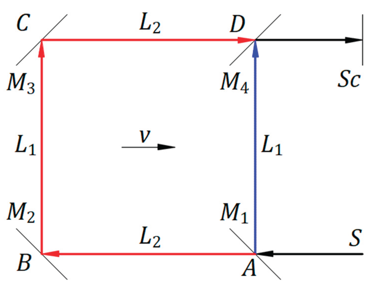
The ether theory and the combination of the two hypotheses that light reflection is a mechanical phenomenon and that light speed is independent of the light source led to theoretical results that were inconsistent with experimental results; therefore, we must reject these two options. This conclusion led us to consider both the reflection and emission of light as mechanical phenomena [5] that explain the Michelson‒Morley experiment and others presented in this article.
Appendix B: Reciprocal Electrodynamic Action of a Magnet and Conductor
A positive or negative electrical charge in a magnetic field , both at rest, form a system in equilibrium in the vacuum of an absolute or inertial frame.
When an electrical charge enters at a velocity perpendicular to a fixed magnetic field , the Lorentz electromagnetic force acts on the charge in motion and is given by the vector product of . The force acts on the electrical charge, continuously changing the direction of its velocity , keeping its magnitude constant. As a result, the electrical charge keeps moving in a circle in the magnetic field with a diameter, depending on the magnitudes of and . When the magnetic field travels at velocity in the opposite direction to the velocity in a straight line in the space of the electrical charge at rest, the relative velocity of the electrical charge with respect to the magnetic field is the velocity . Therefore, the Lorentz electromagnetic force acting on the electric charge is given by the same vector product, , yielding the same result. The electric charge is moving in a circle. The two cases offer a reciprocal electrodynamic interaction between a magnetic field and an electrical charge.
The expression has units of , where is the rate at which electrical charges travel through a conductor per second. Thus, in units, represents the total electrical charge in a conductor of length through which a constant current pumped by an electrical field flows in the direction of the positive charge. Therefore, when the magnet is fixed and the conductor is free to move, the Lorentz repulsive electromagnetic force becomes , which pushes the electrical charges contained in the conductor in the direction given by the vector product. When the magnet is free to move and the conductor is fixed, the Lorentz repulsive electromagnetic force is , which moves the magnet in the opposite direction. The two cases offer a reciprocal electrodynamic interaction between a magnet and a conductor.
The Lorentz right-hand rule and Fleming’s right-hand and left-hand rules are replaced with the following rule, derived from the vector product of for perpendicular vectors. The mobile quantity rotated in the short direction along the fixed quantity gives the direction of the Lorentz force.
Figure A2(a) shows a magnetic field , with its direction perpendicular to the plane of the paper from front to back, and a conductor in the plane of the paper. The magnet and the conductor are in a state of equilibrium when they are at rest to one another, and no current flows through the conductor. The conductor can be connected to a source with an electric field , which pumps an electric current through the conductor.
Suppose the magnet is fixed and the conductor has a degree of freedom in the paper plane in both directions perpendicular to the conductor. Connecting the conductor to an electrical source, a current flows through the conductor from top to bottom. The interaction between the magnetic field and current produces an electromagnetic force of reciprocal repulsion between the conductor and the magnet. In this case, the rotation of the current of the movable conductor in the short direction over the magnetic field of the fixed magnet yields the direction of the repulsive electromagnetic force , which moves the conductor to the right.
Suppose the conductor is fixed and the magnet has a degree of freedom in both directions perpendicular to the conductor. Connecting the conductor to the electrical source, a current flows through the conductor from top to bottom. The interaction between the magnetic field and current produces an electromagnetic force of reciprocal repulsion between the conductor and the magnet. In this case, the rotation of the magnetic field of the movable magnet in the short direction along the current of the fixed conductor yields the direction of the repulsive electromagnetic force , which moves the magnet to the left.
The two cases offer the electromagnetic force of reciprocal repulsion between a magnet and a conductor. Suppose the magnet and the conductor have the same mass in both cases; therefore, the inertial forces have the same magnitude, the relative motion between the conductor and the magnet for the same current is identical, and the two phenomena are symmetrical. In both cases, the electromagnetic force has to overcome the inertial force of the conductor or magnet, respectively.
Figure A2.
(a) An electrical current through a conductor in a magnet’s magnetic field. (b) Moving a conductor or magnet when they are in proximity.
Figure A2.
(a) An electrical current through a conductor in a magnet’s magnetic field. (b) Moving a conductor or magnet when they are in proximity.
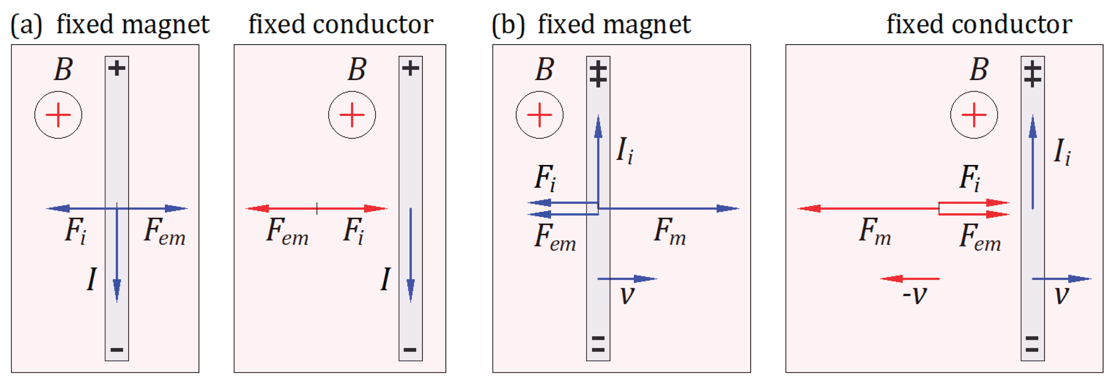
Figure A2(b) illustrates a magnetic field , with its direction perpendicular to the plane of the paper from front to back, and a conductor in the plane of the paper. At rest or in motion, a magnet does not generate an electric field in the absence of a conductor. According to his time, Einstein considered that an electric field does not arise in a fixed conductor in the neighborhood of a moving magnet. Here, we explain that an electric field arises in the conductor at rest/in motion when the magnet is in motion/at rest.
Suppose the magnet is fixed and the conductor has a degree of freedom in the paper plane in both directions perpendicular to the conductor. The conductor connected to a galvanometer is forced to move to the right by a mechanical force at velocity , which is also the velocity of electrons from within the conductor. The Lorentz electromagnetic force is . The rotation of the velocity of electrons in the short direction over the magnetic field of the fixed magnet gives the electrons a moving direction toward the bottom end of the conductor, and the positive electrical charges a moving direction toward the top of the conductor. Therefore, an electromotive force (emf) within the conductor arises. The conductor acts as a source, and the induced electric field from the positive end to the negative end within the conductor creates an induced current that flows through the galvanometer from the top positive end to the bottom negative end of the conductor.
The interaction of the magnetic field and current produces an electromagnetic force of reciprocal attraction . In this case, the rotation of of the movable conductor in the short direction along of the fixed magnet yields the direction of the electromagnetic force that opposes . As long as moves the conductor at the velocity , the induced current flows through the galvanometer.
Suppose that the conductor connected to the galvanometer is fixed, and the magnet has one degree of freedom in both directions perpendicular to the conductor, which belongs to the plane of the paper. The magnet is forced to move to the left by mechanical force at velocity , which is also the opposite velocity of electrons from within the conductor. Because the relative velocity of electrons within the conductor with respect to the relative rest of the magnetic field is velocity , Lorentz’s electromagnetic force has the same form . The rotation of the relative velocity of electrons with the conductor in the short direction over the relative rest of the magnetic field gives the electrons a direction of motion toward the bottom end of the conductor, and the positive electrical charges a direction of motion toward the top of the conductor. Therefore, an electromotive force (emf) within the conductor arises. The conductor acts as a source, and the induced electric field from the positive end to the negative end within the conductor creates an induced current that flows through the galvanometer from the top positive end to the bottom negative end of the conductor.
The interaction of the magnetic field of the movable magnet and the current through the conductor at rest produces an electromagnetic force of reciprocal attraction . In this case, the rotation of in the short direction over yields the direction of the electromagnetic force that opposes . As long as moves the conductor at the velocity , the induced current flows through the galvanometer.
The two cases offer the electromagnetic force of reciprocal attraction between a magnet and a conductor. Suppose the magnet and the conductor have the same mass in both cases; therefore, the inertial forces have the same magnitude, the relative motion between the conductor and the magnet for the same force is identical, and the two phenomena are symmetrical. In both cases, the mechanical force has to overcome the electromagnetic force and the inertial force of the conductor or magnet, respectively.
References
- Idema T. Mechanics and Relativity, 2019th ed. TU Delft Open, Delft, The Netherlands, 2019), p. 46.
- Filipescu F. D. Reflection of Light as a Mechanical Phenomenon Applied to a Particular Michelson Interferometer. Preprints 2020, 2020090032 (doi:10.20944/preprints202009.0032.v1). [CrossRef]
- Filipescu F. D. Opposing hypotheses of the reflection of light applied to the Michelson interferometer with a particular geometry. Phys. Essays 2021, 34, 3, 268-273. [CrossRef]
- Filipescu F. D. Opposing hypotheses of the reflection of light applied to the Michelson interferometer. Phys. Essays 2021, 34, 3, 389-396.
- Filipescu F. D. Emission, propagation, and reflection of light as mechanical phenomena in inertial frames. Phys. Essays 2021, 34, 4, 587-590. [CrossRef]
- Filipescu F. D. Observation of a star orbit based on the emission and propagation of light as mechanical phenomena. Phys. Essays 2022, 35, 2, 111. [CrossRef]
- Filipescu F. D. Emission, propagation, and reflection of light as mechanical phenomena. Preprints 2022, 2022040061. [CrossRef]
- Filipescu F. D. Emission, propagation, and reflection of light as mechanical phenomena: General considerations. Phys. Essays 2022, 35, 3, 266-269. [CrossRef]
- Filipescu F. D. Velocity of light through a moving medium applied to the Fizeau experiment. Phys. Essays 2023, 36, 1, 90-93. [CrossRef]
- Filipescu F. D. Reflection of light as a mechanical phenomenon applied to the Michelson interferometer with sunlight as a source. Preprints 2022, 2022080472 (doi:10.20944/preprints202208.0472.v1). [CrossRef]
- Filipescu F. D. Reflection of light as a mechanical phenomenon applied to the Michelson interferometer with sunlight as a source. Phys. Essays 2023, 36, 2, 223-229. [CrossRef]
- Filipescu F. D. Airy’s experiment and the dragging of light by a moving medium. Phys. Essays 2023, 36, 3, 274-276. [CrossRef]
- Filipescu F. D. Emission, propagation, and reflection of light as mechanical phenomena applied to the Majorana experiment. Phys. Essays 2023, 36, 4, 361-368. [CrossRef]
- Filipescu F. D. Experiment on the reflection and emission of light. Phys. Essays 2024, 37, 1, 64-70. [CrossRef]
- Michelson A. A. Morley E. W. On the relative motion of the earth and the luminiferous ether. Am. J. Sci. 1887, s-3-34(203), 333–345.
- Ritz W. Recherches critiques sur l’Électrodynamique Générale. Ann. Chim. Phys. 1908, 13, 145.
- Alvager T., Farley F. J. M., Kjellman J., and Wallin L. Test of the second postulate of special relativity in the GeV region. Phys. Lett. A. 1964 12, 260-262. [CrossRef]
- De Sitter W. A proof of the constancy of the velocity of light. Proc. R. Neth. Acad. Arts and Sci. 1913, 15(II), 1297-1298.
- De Sitter W. On the constancy of the velocity of light. Proc. R.Neth. Acad. Arts and Sci. 1913, 16, 395-396.
- Miller D. C. Ether-Drift Experiments at Mount Wilson. Proc. Natl. Acad. Sci. U. S. A. 1925 11, 306-314. [CrossRef]
- Airy G. B. On a supposed alteration in the amount of Astronomical Aberration of Light, produced by the passage of the Light through a considerable thickness of Refracting Medium. Proc. R. Soc. Lond. 1871, 20, 35.
- Majorana Q. On The Second Postulate of the Theory of Relativity: An Experimental Demonstration of the Constancy of the Velocity of Light Reflected by a Moving Mirror. Phys. Rev. 1918, 11, 411. [CrossRef]
- Einstein A. Zur Elektrodynamik bewegter Körper. AdP 1905 322 (10): 891921. (English translation: https://www.fourmilab.ch/etexts/einstein/specrel/specrel.pdf). 10.
- Lorentz H. A. The Relative Motion of the Earth and the Aether. Zittingsverlag Akad. V. Wet. 1892 (1), 74.
- FitzGerald G. F. Letters to the editor. 1889. (https://www.science.org/doi/10.1126/science.ns-13.328.390.a).
- Bărbulescu N. Physics foundations of Einsteinian relativity (St. & Enc. ed. Bucharest, Romania 1975), pp. 66-77.
Figure 1.
A ball brought from rest to a velocity v.
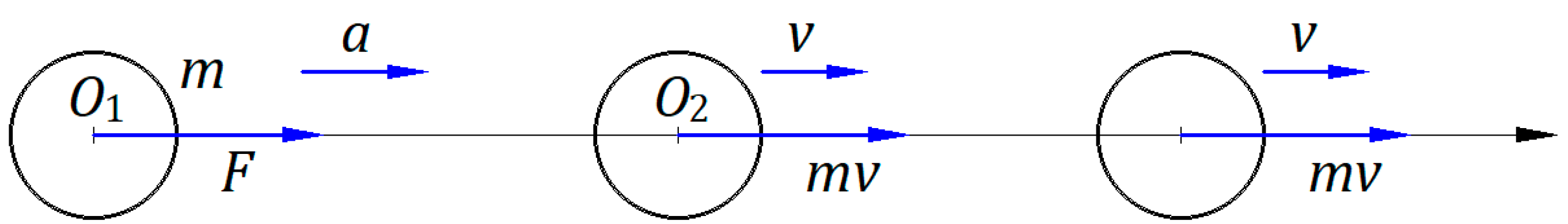
Figure 2.
A moving source at velocity v emits a ball at a velocity V.
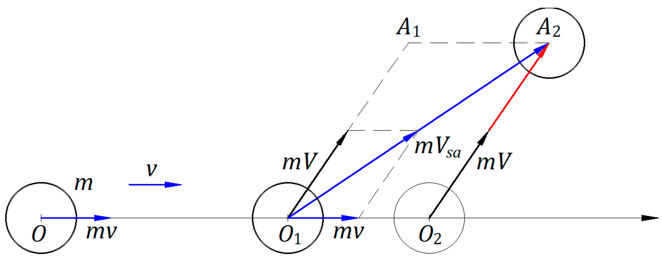
Figure 3.
Ballistic law applies to balls emitted by a source in motion.
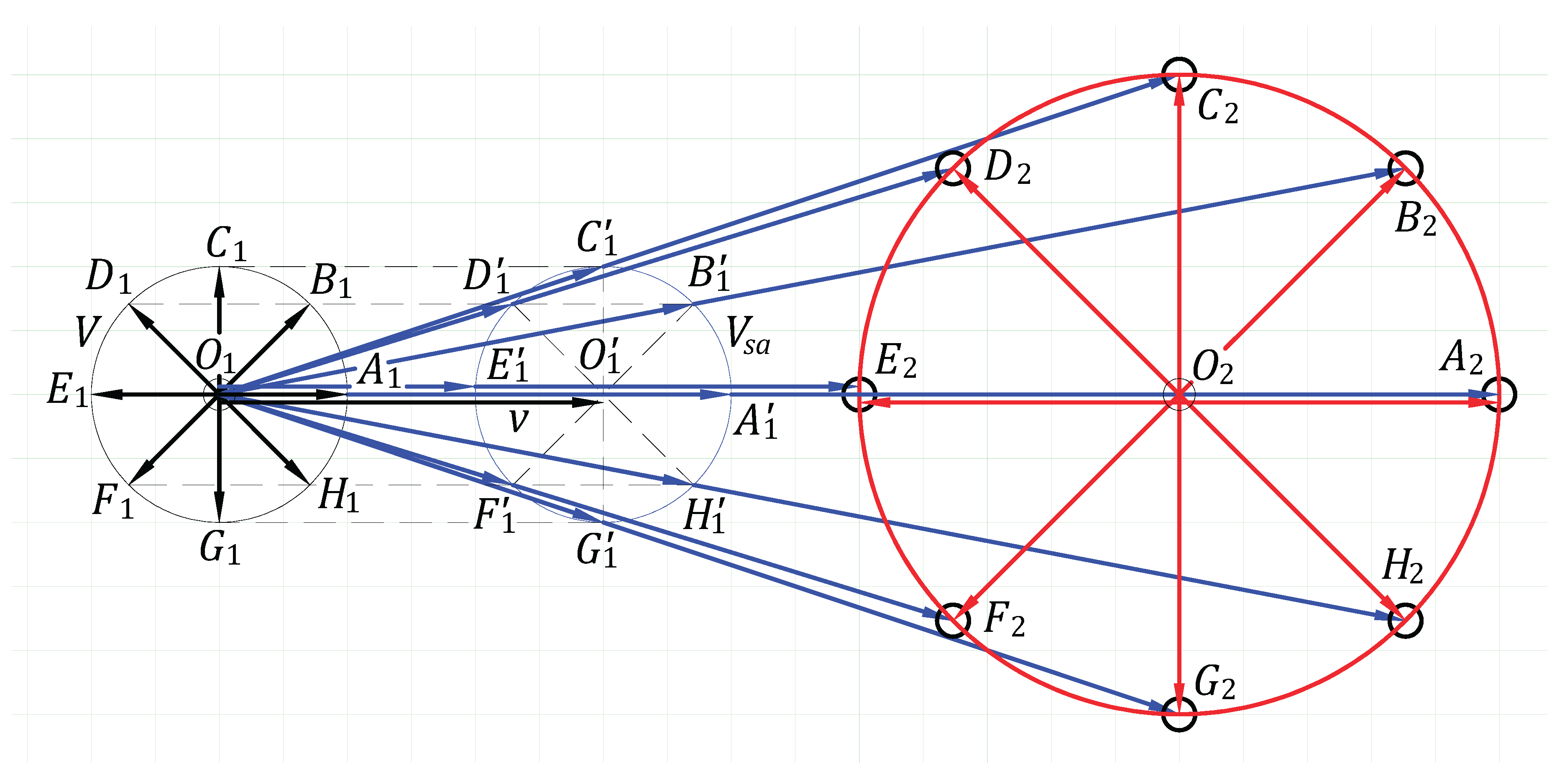
Figure 4.
Elastic collision of two balls moving in opposite directions.
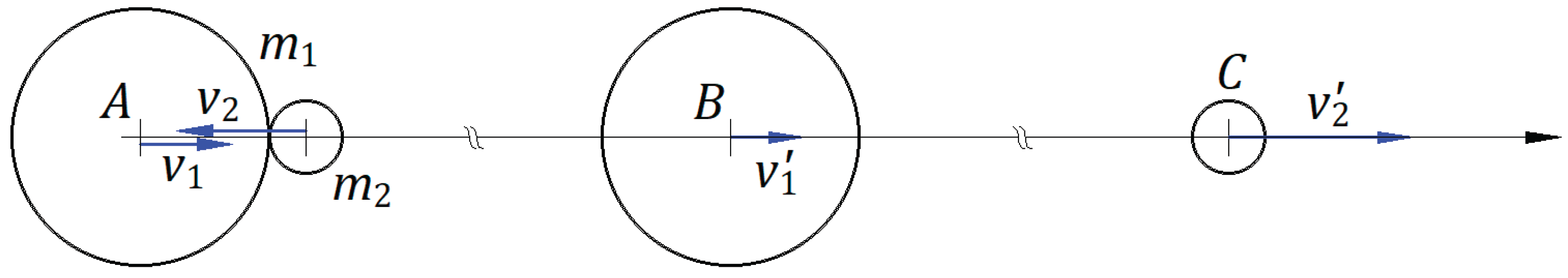
Figure 5.
Elastic collision of a wall and a ball moving in opposite directions.
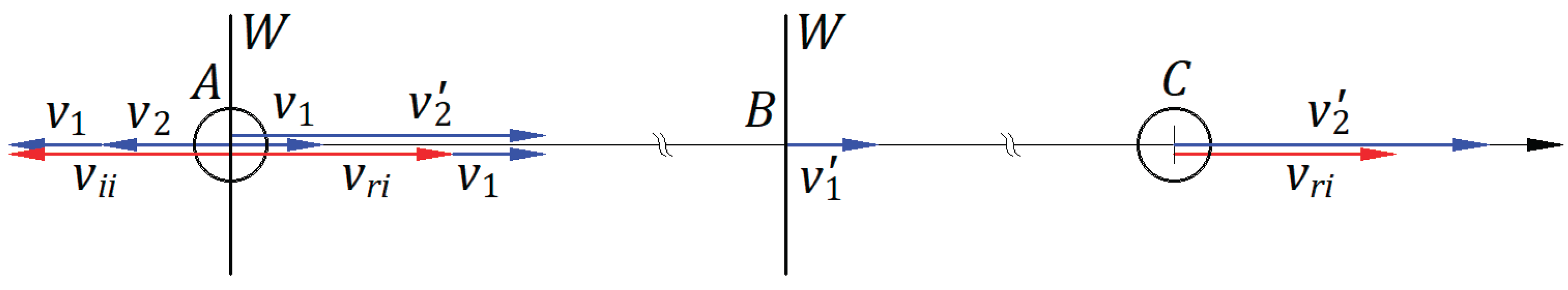
Figure 6.
Elastic reflection of a ball by a moving wall.
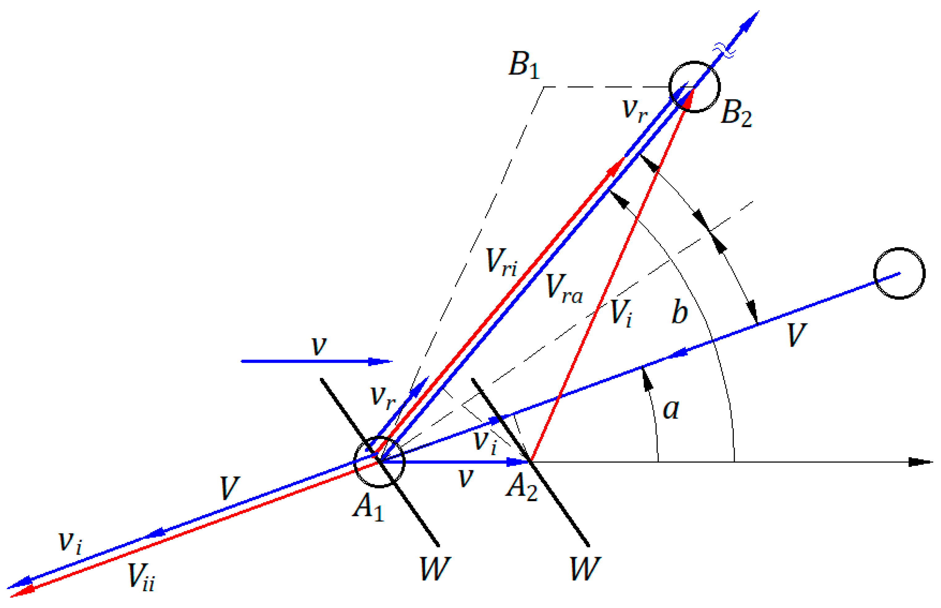
Figure 7.
Emission, propagation, and reflection of balls in the absolute frame and an inertial frame.
Figure 7.
Emission, propagation, and reflection of balls in the absolute frame and an inertial frame.
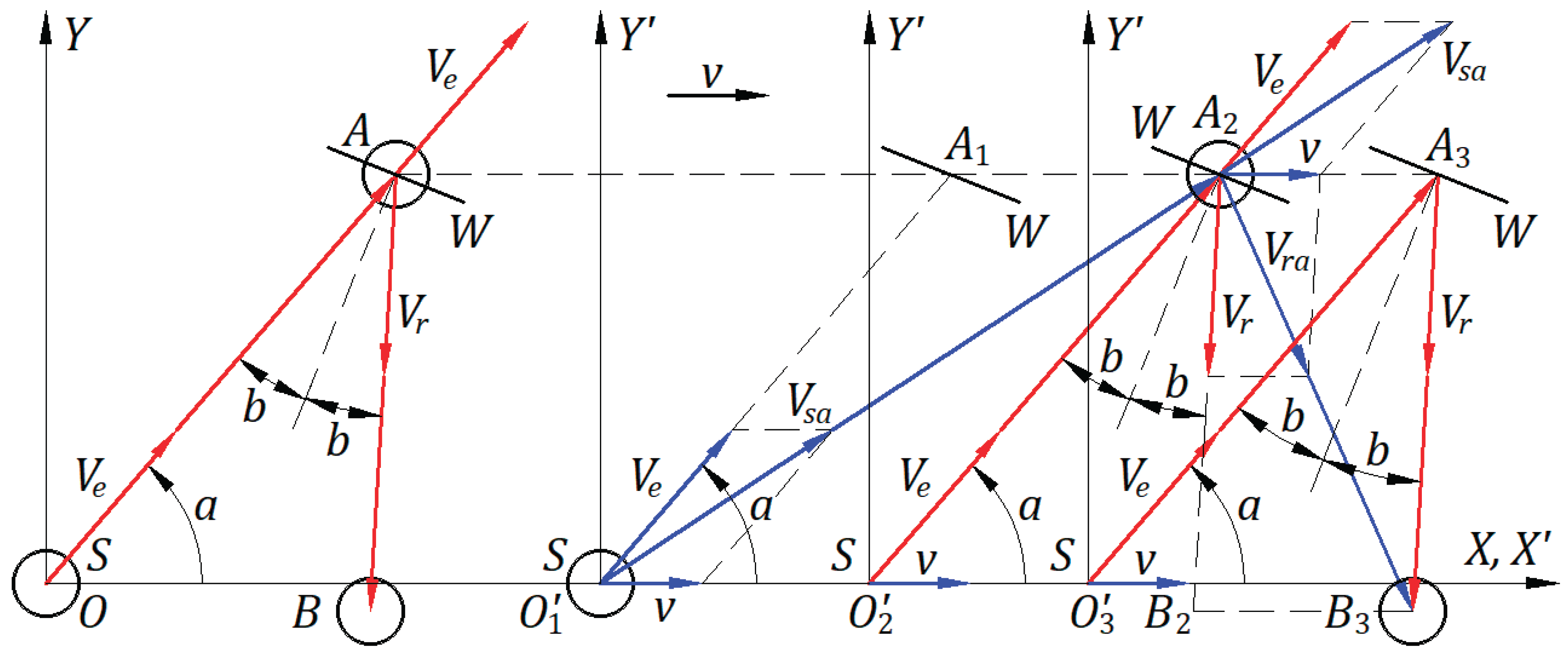
Figure 8.
Ballistic law applies to wavefronts of light emitted by a source in motion.
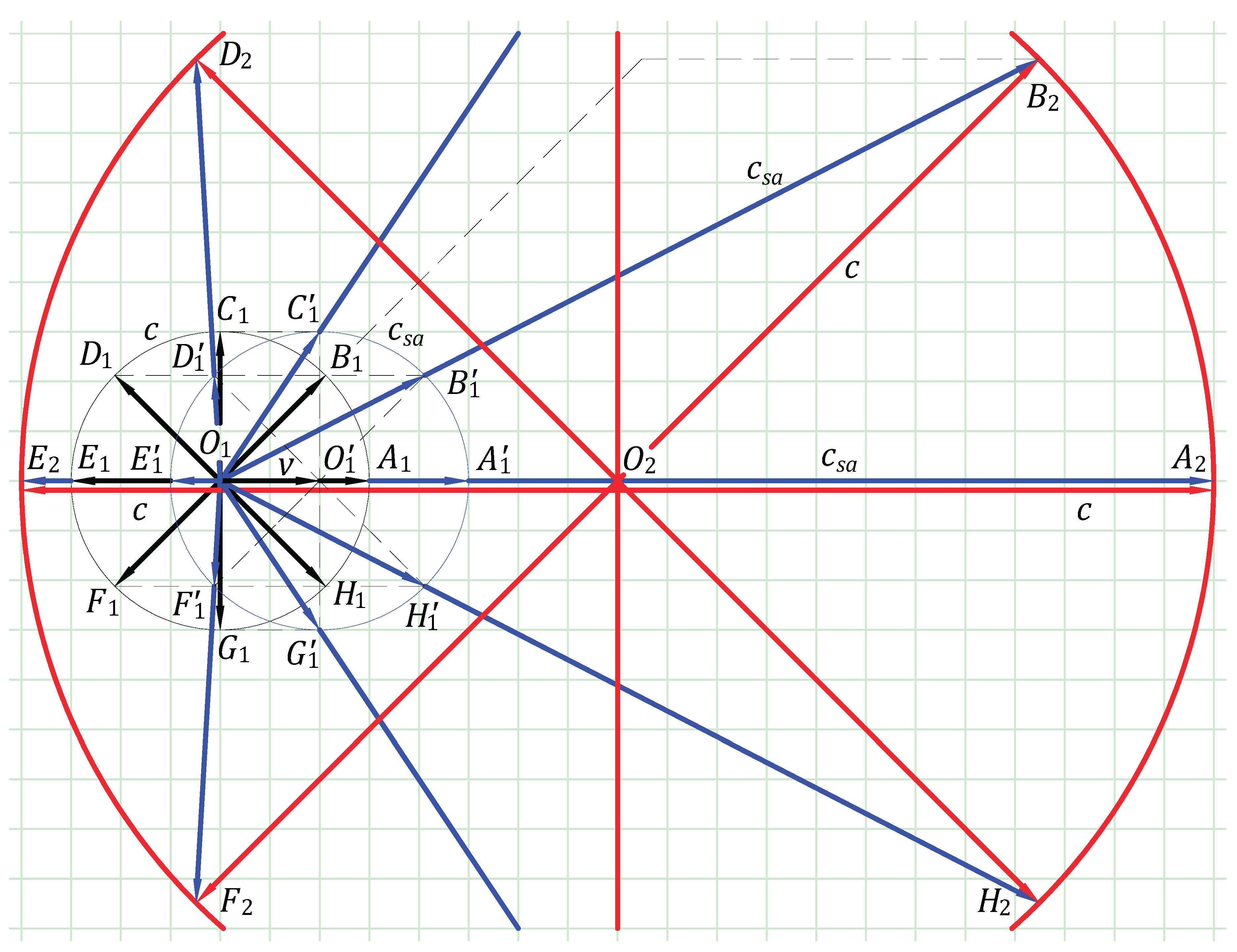
Figure 9.
Reflection of light by a moving mirror.
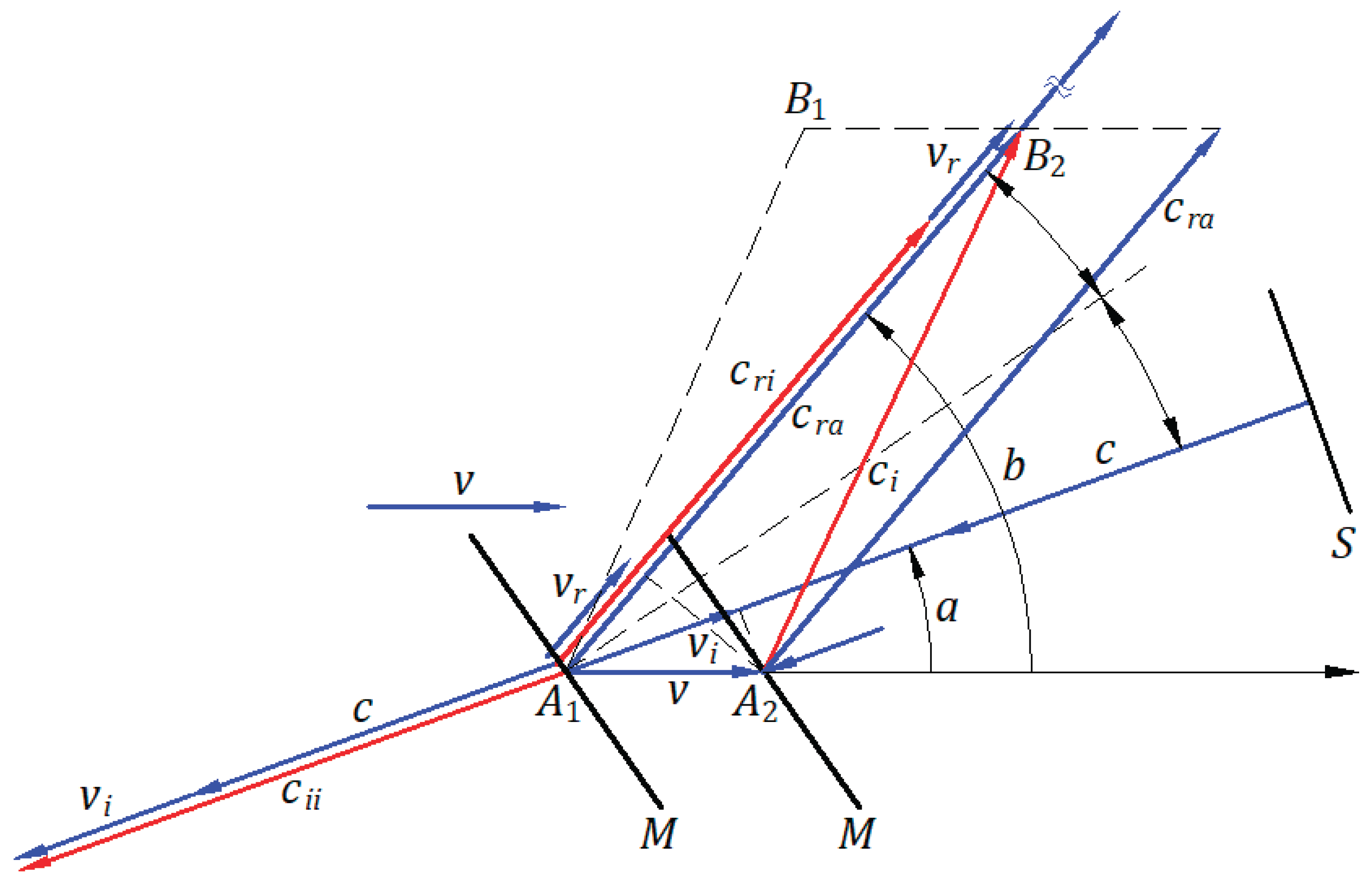
Figure 10.
Emission, propagation, and reflection of light in the absolute frame and an inertial frame.
Figure 10.
Emission, propagation, and reflection of light in the absolute frame and an inertial frame.
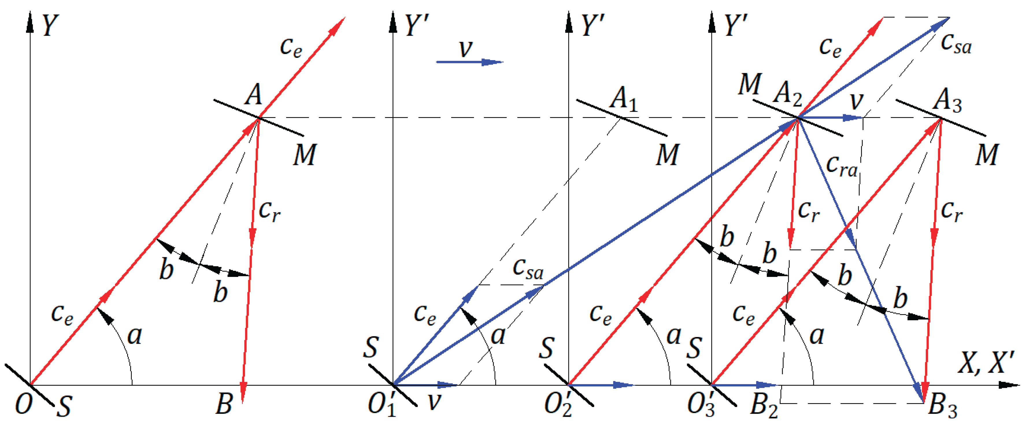
Figure 11.
A boson as a carrier decaying at a mechanical speed v near the speed of light c.
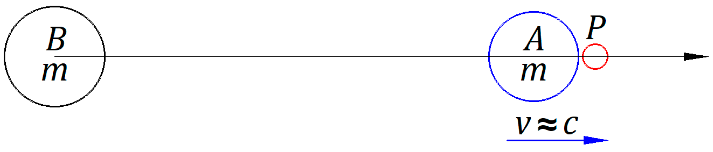
Figure 12.
Observation of a star in the universe, considering: (a) the ballistic law of light and (b) the constancy of light speed.
Figure 12.
Observation of a star in the universe, considering: (a) the ballistic law of light and (b) the constancy of light speed.
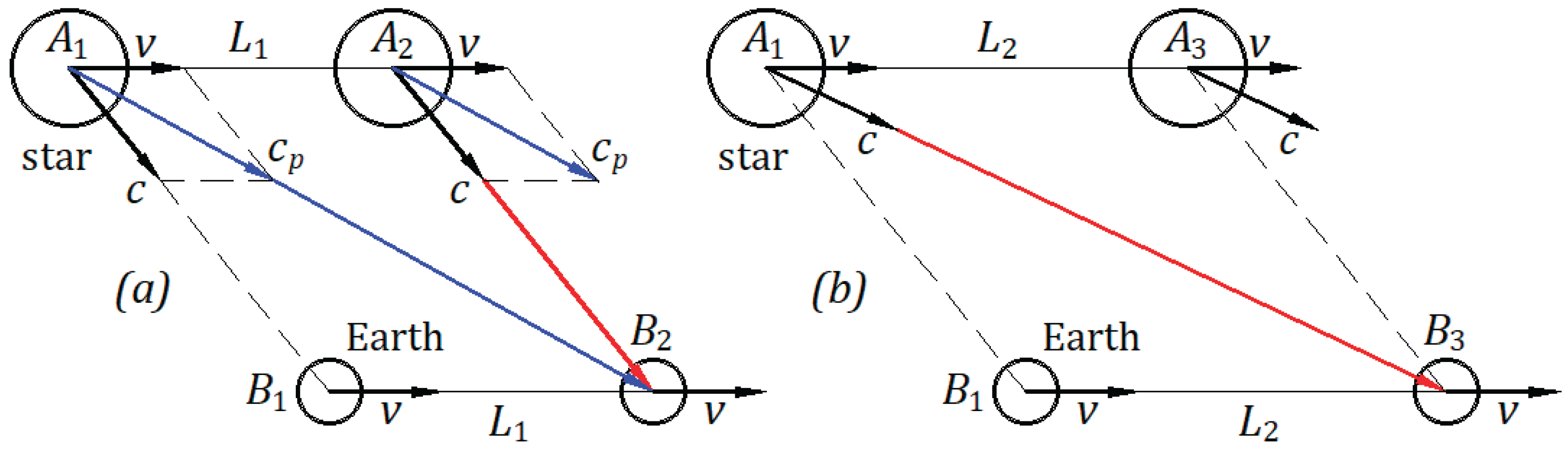
Figure 13.
Observation of a star’s orbit.
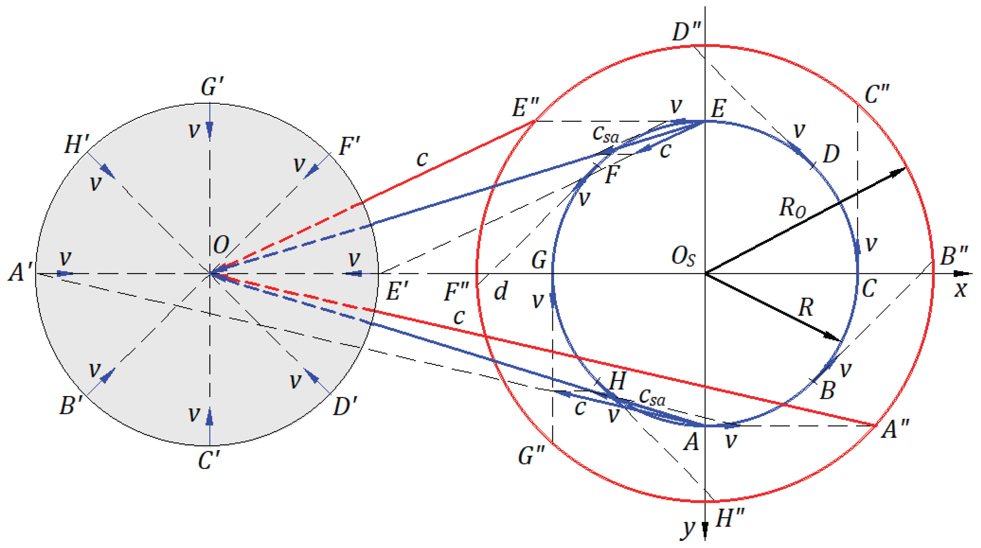
Figure 14.
Galilean coordinates of a circular wavefront of light from a stationary frame shared in an inertial frame.
Figure 14.
Galilean coordinates of a circular wavefront of light from a stationary frame shared in an inertial frame.
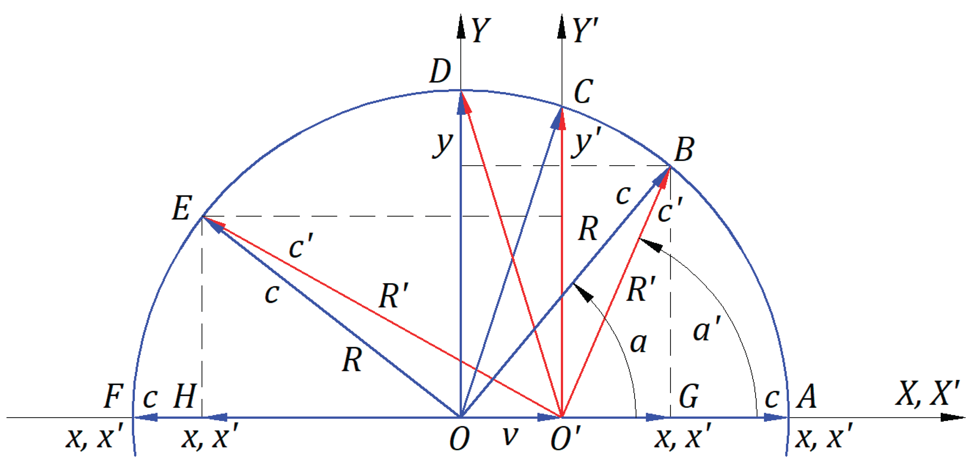
Figure 15.
The Lorentz transformation is applied to a circular wavefront of light from a stationary frame to an inertial frame.
Figure 15.
The Lorentz transformation is applied to a circular wavefront of light from a stationary frame to an inertial frame.
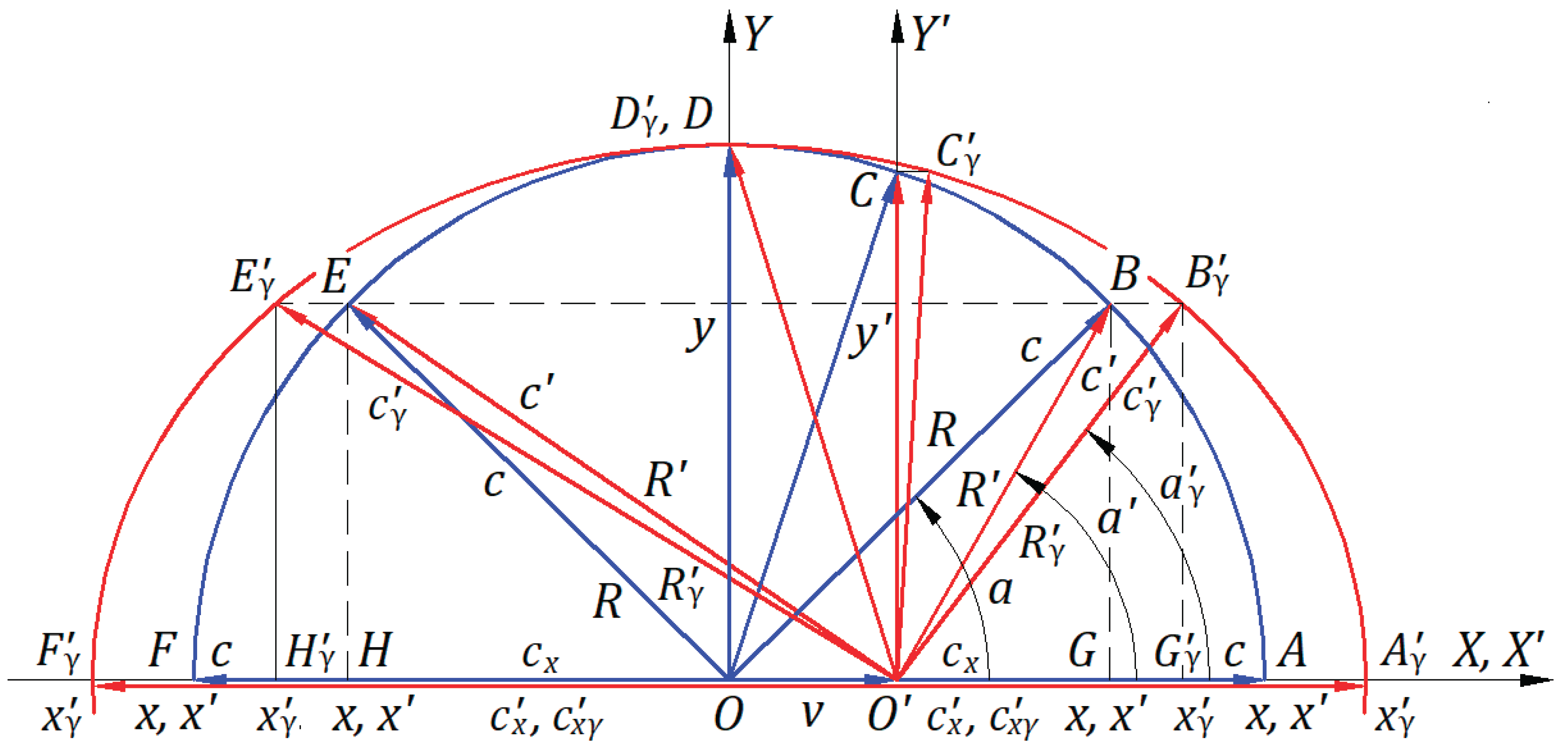
Figure 16.
The simplified transformation applied to the waves of a circular wavefront emitted by a source belonging to the origin of the inertial frame at the instant when the origin of both frames coincides, and the ballistic law is ignored.
Figure 16.
The simplified transformation applied to the waves of a circular wavefront emitted by a source belonging to the origin of the inertial frame at the instant when the origin of both frames coincides, and the ballistic law is ignored.
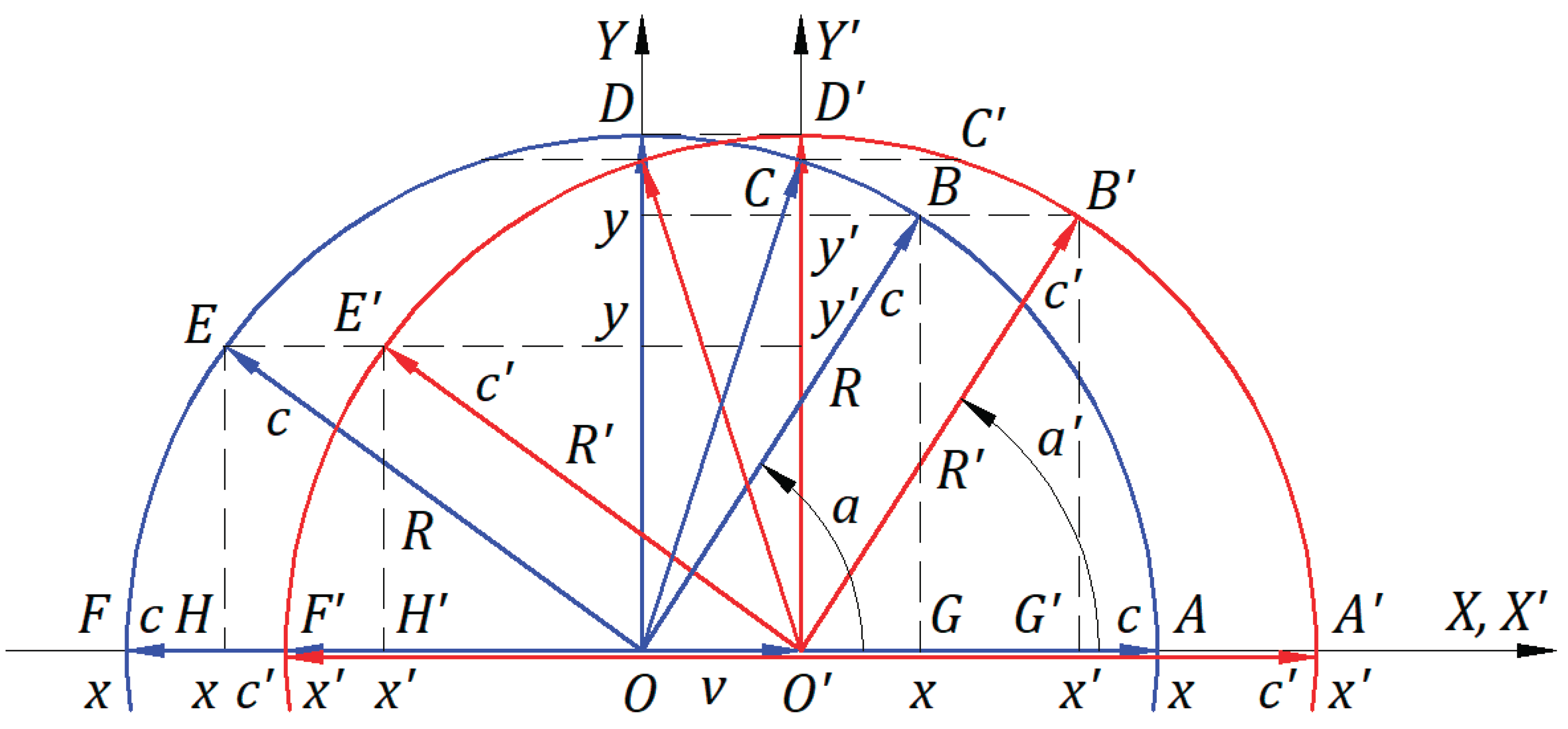
Figure 17.
The light paths given in number of wavelengths: (a) For waves emitted by a source at rest. (b) For waves emitted by a moving source, ignoring the ballistic law. (c) For waves emitted by a moving source, when considering the ballistic law.
Figure 17.
The light paths given in number of wavelengths: (a) For waves emitted by a source at rest. (b) For waves emitted by a moving source, ignoring the ballistic law. (c) For waves emitted by a moving source, when considering the ballistic law.
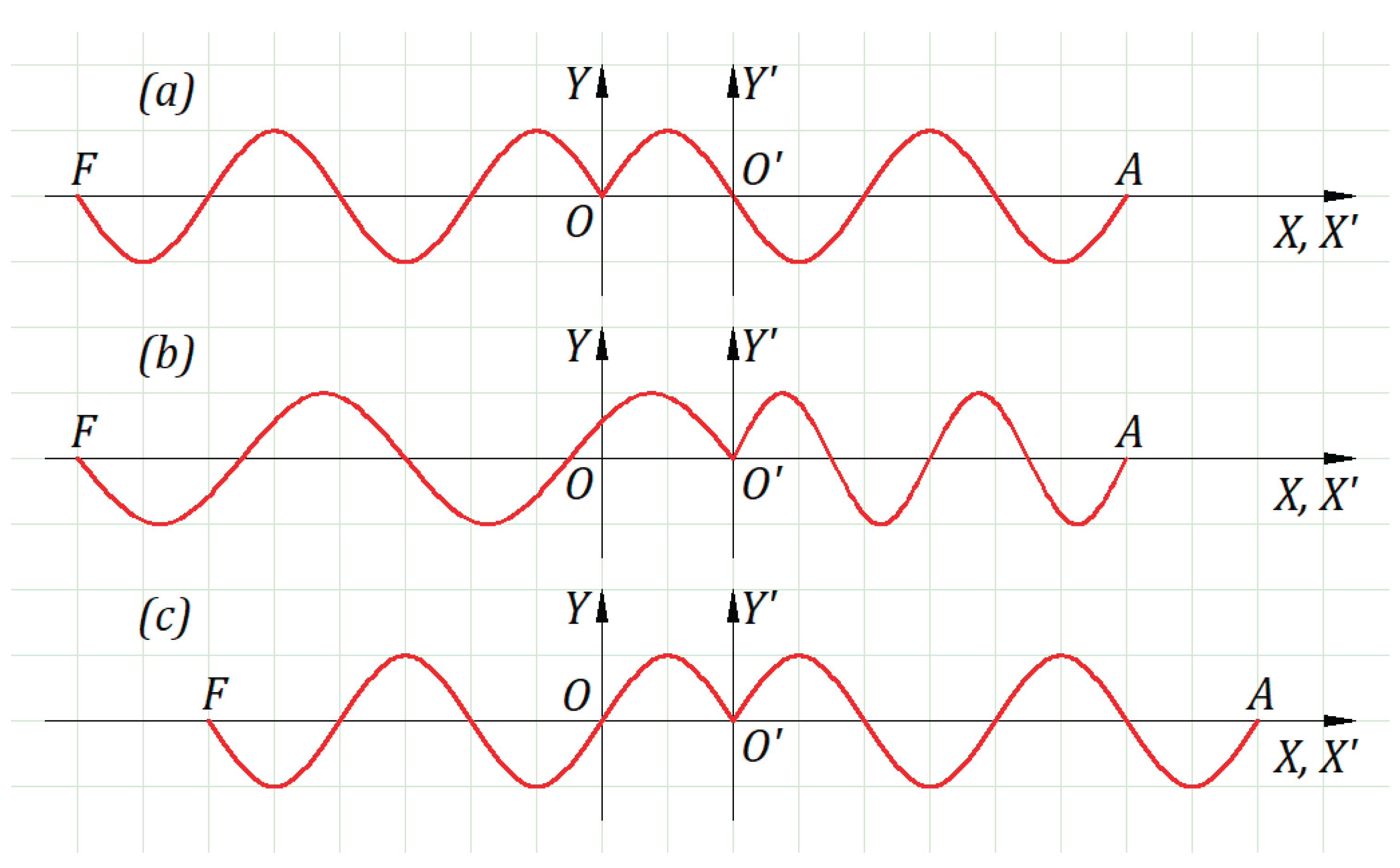

Table 1.
Numerical calculation for the absolute lengths , , and with their corresponding speeds, and the hypothesized time ; all functions of angle at the time s.
Table 1.
Numerical calculation for the absolute lengths , , and with their corresponding speeds, and the hypothesized time ; all functions of angle at the time s.
| [°] | 0 | 30 | 60 | ||
| [m] | 2.99970000000000E+08 | 2.59777621135332E+08 | 1.49970000000000E+08 | ||
| [m/s] | 2.99970000000000E+08 | 2.59777621135332E+08 | 1.49970000000000E+08 | ||
| [m] | 2.99970001499850E+08 | 2.59777622434220E+08 | 1.49970000749850E+08 | ||
| [m/s] | 2.99970001499850E+08 | 2.59777622434220E+08 | 1.49970000749850E+08 | ||
| [m] | 2.99970001499850E+08 | 2.99974020737757E+08 | 2.99985001499925E+08 | ||
| [m/s] | 3.00000000000000E+08 | 3.00000000000000E+08 | 3.00000000000000E+08 | ||
| [s] | 9.99900004999500E-01 | 9.99913402459189E-01 | 9.99950004999750E-01 | ||
| [m] | 3.00000001499850E+08 | 2.59807622434220E+08 | 1.50000000749850E+08 | ||
| [°] | 89.99427042203910 | 90 | 120 | ||
| [m] | 2.41565430769697E-07 | 2.99999999999816E+04 | 1.50030000000000E+08 | ||
| [m/s] | 2.41565430769697E-07 | 2.99999999999816E+04 | 1.50030000000000E+08 | ||
| [m] | 2.41565431977524E-07 | 3.00000001499816E+04 | 1.50030000750150E+08 | ||
| [m/s] | 2.41565431977524E-07 | 3.00000001499816E+04 | 1.50030000750150E+08 | ||
| [m] | 2.99999998500000E+08 | 3.00000001500000E+08 | 3.00015001500075E+08 | ||
| [m/s] | 3.00000000000000E+08 | 3.00000000000000E+08 | 3.00000000000000E+08 | ||
| [s] | 9.99999995000000E-01 | 1.00000000500000E+00 | 1.00005000500025E+00 | ||
| [m] | 3.00000000002416E+04 | 3.00000000000000E+04 | 1.50000000750150E+08 | ||
| [°] | 150 | 180 | |||
| [m] | 2.59837621135332E+08 | 3.00030000000000E+08 | |||
| [m/s] | 2.59837621135332E+08 | 3.00030000000000E+08 | |||
| [m] | 2.59837622434520E+08 | 3.00030001500150E+08 | |||
| [m/s] | 2.59837622434520E+08 | 3.00030001500150E+08 | |||
| [m] | 3.00025982262243E+08 | 3.00030001500150E+08 | |||
| [m/s] | 3.00000000000000E+08 | 3.00000000000000E+08 | |||
| [s] | 1.00008660754081E+00 | 1.00010000500050E+00 | |||
| [m] | 2.59807622434520E+08 | 3.00000001500150E+08 | |||
Disclaimer/Publisher’s Note: The statements, opinions and data contained in all publications are solely those of the individual author(s) and contributor(s) and not of MDPI and/or the editor(s). MDPI and/or the editor(s) disclaim responsibility for any injury to people or property resulting from any ideas, methods, instructions or products referred to in the content. |
© 2025 by the authors. Licensee MDPI, Basel, Switzerland. This article is an open access article distributed under the terms and conditions of the Creative Commons Attribution (CC BY) license (http://creativecommons.org/licenses/by/4.0/).
Copyright: This open access article is published under a Creative Commons CC BY 4.0 license, which permit the free download, distribution, and reuse, provided that the author and preprint are cited in any reuse.


