Submitted:
08 December 2023
Posted:
13 December 2023
You are already at the latest version
Abstract
The two-stage direct thermal contact (2sDTC) process is a rapid dewatering approach for fluid fine tailings (FFT) that is integrated into an oil sands bitumen extraction plant to reduce tailings pond storage and freshwater usage. In the first stage, combustion gas directly contacts atomized FFT, vaporizing water and yielding dry solids and steam-rich hot gas. The second stage involves pond effluent water directly contacting the steam-rich hot gas, recovering heat and condensing moisture. Case studies confirm the technical feasibility of the integration. Benefits include producing a dry discharge, reducing tailings water discharge and conserving an equivalent to 0.2 barrels of freshwater per barrel of oil produced. Most importantly, these benefits incur no additional energy cost to the plant as the integration eliminates the energy penalty and CO2 emissions associated with FFT dewatering. Further capacity enhancement can be achieved by using centrifuge-concentrated FFT. The study reveals that FFT concentrated to ~50 wt% solids could still maintain its pump-ability and be accommodated by the 2sDTC process, leading to an integration which could dewater more FFT annually and conserve more freshwater ( 0.58 barrels per barrel of oil produced), with the sole energy requirement being the power to drive the centrifuge machinery.
Keywords:
surface mining
; fluid fine tailing (FFT)
; mature fine tailings (MFT)
; tailings dewatering
; thermal drying
; FFT centrifuge
; tailings storage
; pond reclamation
; water saving
1. Introduction
Canada possesses the world’s fourth-largest proven oil reserves, accounting to 173 billion barrels, after Venezuela, Saudi Arabia, and Iran, with 97% located in the oil sands (167 billion barrels) [1]. Approximately 20% of the oil sands reserves are recoverable through surface mining. In this method, oil sands ore is transported from the mining site to extraction plants where bitumen is separated using a combination of hot water, steam and diluent (naphthenic, paraffinic) [1,2,3]. After separation from the bitumen and diluent, the remaining components including sand, water, fine clays and minerals – collectively referred to as tailings – are discharged to tailings ponds, as illustrated in Figure 1. Within these ponds, a layer of clarified water (with less than 1 wt% solids), commonly known as pond effluent water (PEW), accumulates on the surface, while the sands gradually settle at the pond’s bottom via sedimentation. Between these layers exists a layer of initial fluid with a relatively low solids content (between 15 wt% and 30 wt%), known as thin fine tailings (TFT). Over time, further settling leads to the formation of higher solids content tailings (exceeding 30 wt%), termed mature fine tailings (MFT) [4]. Further densification of the MFT to a solid state is extremely slow – taking perhaps more than a century [5]. This fluid fine tailing (FFT), including TFT and MFT, has no practical utility and has been accumulated in tailings ponds since the first oil sands surface mining operation started in 1967. The overall volume of fluid tailings, encompassing both historical and recent discharge, within the Athabasca oil sands region, saw an increase from 1075 million cubic metres (Mm³) in 2014 to 1360 Mm³ in 2020 [6]. The magnitude of such extensive tailings accumulation stands as a profound environmental challenge for surface mining operations in the oil sands industry.
Illustrated in Figure 2 is a diagram with the material balance of an example oil sands bitumen extraction plant that is based on the Clark Hot Water Extraction (CHWE) process [7,8,9,10]. The plant yields 2,318 t/h of diluted bitumen (equivalent to 200,000 barrels per day) from 12,187 t/h of oil sands ore. It necessitates 1,873 t/h of freshwater for the extraction process and 125 t/h of freshwater for utility plant requirements. A total of 24,624 t/h of tailings is discharged to the tailings pond, while 12,337 t/h is stored within which constitutes a blend of water, solids and residual bitumen. A cumulative 12,306 t/h of PEW is reclaimed from the pond, with 3,726 t/h allocated for cold water purposes and 8,578 t/h designed for hot water production. The necessary energy to heat PEW comes from the plant’s waste heat and a stream of low-pressure steam (LPS) originating from the utility plant. The utility plant operates as a co-generation system, consisting of natural gas turbines, heat recovery steam generators (HRSG), and auxiliary boilers. Apart from supplying the LPS, it also produces power (127.3 MW) and medium pressure steam (MPS, 435 t/h) essential for stripping and secondary separation. Among this, only the MPS utilized for stripping (105 t/h) is consumed and subsequently discharged alongside the tailings. The remaining steam (MPS 330 t/h and LPS 301 t/h) is condensed and returned to the utility plant.
Another pressing environmental challenge confronting oil sands surface mining pertains to the substantial consumption of freshwater and natural gas. Within the context of bitumen extraction, around 20% of the water used constitutes fresh makeup water. In 2021, a total of slightly over 968 Mm³ of water facilitated the production of about 646 million barrels of oil equivalent (BOE) via oil sands mining [11]. Fresh makeup water accounted for 198 Mm³ of this figure. To gauge water performance in mining, water use intensity, denoting the volume (measured in barrels) of makeup water necessary to yield one BOE, is employed. In 2021, diverse oil sands mines exhibited varied water use intensities, ranging from 1.15 to 3.17 BOE, with an average of 1.92 BOE. Water use intensity in 2022 was 2.9 BOE [1]. The surface mining coupled with upgrading, on average, utilizes 0.6 thousand cubic feet of purchased natural gas per barrel of bitumen produced in 2022 [12]. Consequently, this process incurred an approximate emission of 30 kg of CO2 per barrel of bitumen produced, as per Carbon Dioxide Emissions Coefficients by Fuel EIA 2022 [12,13].
In essence, oil sands surface mining operations confront challenges related to expanding tailings storage and substantial freshwater utilization. In addition, oil sands surface mining relies on hot water and steam, magnifying energy consumption and greenhouse gas emissions. In response, endeavors to enhance bitumen extraction rates, minimize energy and water consumption, and expedite tailings drying have become focal points of research and development for stakeholders including universities, the Canadian oil industry (e.g., Oil Sands Innovation Alliance - COSIA), and governmental bodies at various tiers (e.g., Alberta Innovates and Natural Resources Canada).
One avenue of exploration involves the development of novel processes aimed at achieving heightened bitumen extraction rates while necessitating diminished water usage and caustic additives, ultimately leading to reduced tailings. The bitumen liberation from sand grains is dependent on the balance between forces pulling the bitumen away from the sand grains and forces of bitumen adhering to these grains [3]. In the context of the Clark Hot Water Extraction (CHWE) process, caustic additives, predominantly in the form of sodium hydroxide (NaOH), are introduced into hot water to enhance bitumen extraction efficiency by generating surfactants – the active agents for bitumen liberation. Nonetheless, it has been observed that NaOH exacerbates the challenge of dewatering FFT due to the accumulation of Na+ ions in process water, dispersing silt-clay particles (ranging from 2µm to 44µm) that constitute the primary FFT content [10,14]. A comparative study involving modeling and experimentation examined the consolidation of caustic and non-caustic oil sands tailings [15]. Non-caustic tailings were found to consolidate at a significantly accelerated rate compared to their caustic counterparts. The findings indicate that embracing non-caustic bitumen extraction processes may yield substantial enhancements in water recycling rates, a reduced dependence on freshwater, and considerable containment size reduction. In the quest for alternative additives, investigations into the feasibility of using lime (CaO) or ammonia hydroxide (NH4OH) as bitumen extraction process aids concluded that both lime and ammonia hydroxide hold promise [14,16,17,18]. The incorporation of pressure cycles into the hot water extraction process, specifically a non-caustic extraction technique entailing repeated cycles of gas-driven compression and venting-triggered decompression, exhibited potential in mitigating the use of caustic additives [19]. Additionally, solvent-assisted ambient aqueous bitumen extraction (SA3BE) processes, by taking advantage of solvents (e.g., kerosene, petroleum diesel and biodiesel) and frothers (e.g., methyl isobutyl carbinol) as well as polymeric demulsifiers (e.g., cellulose derivatives, polyoxyalkylates, ethylene oxide-propylene oxide, ethylcellulose), showed the ability of processing oil sands at ambient temperature resulting in reduced energy consumption and GHG emissions, a more complete bitumen recovery, a higher bitumen froth quality and a faster tailings settling [20,21]. Nonetheless, there exist barriers demanding resolution before process modifications can be effectively scaled up for commercial implementation. Barriers identified by experts for both emerging technologies and incremental process changes were corporate inertia and technology lock-in due to the sunk costs of existing infrastructure. Uncertainty about the potential performance of new processes once deployed commercially, was consistently ranked as the biggest barrier preventing the adoption of new process technologies [22].
Another avenue involves the development of technologies to address the treatment of FFT within the containment ponds. A multitude of technologies have been identified, scrutinized, and evaluated from fundamental, practical, and economic standpoints, encompassing mechanical, chemical, and biological approaches[23,24]. Through an assessment of the merits and drawbacks of these diverse technologies, reviews underscore that a "silver bullet" tailings technology, a single approach or suite of methods capable of comprehensively addressing all oil sands tailings challenges, has yet to emerge. One of the scrutinized technologies involves thermal drying of FFT, a process by heating tailings within an oven or kiln to decrease moisture content. This technique claims a rapid water removal capability, surpassing all other dewatering methods. However, its pursuit is hampered by its high energy costs, which may constitute an upper limit for FFT treatment [23]. Additionally, knowledge gaps exist regarding the environmental impact arising from the vapor generated during FFT thermal drying. Thermal drying is meant to be applied primarily to tailings products that have already been partially dewatered by other processes such as centrifuge technology, otherwise the high energy penalty will hinder its applications [24]. Techniques that combine centrifuge and a direct heated dispersion type dryer to dewater FFT were investigated, and potential heat recovery was evaluated [25,26].
Currently all oil sands mining sites employ co-generation to supply both site electrical load and process heat, practicing energy recovery from on-site processing [27]. For instance, the bitumen extraction plant shown in Figure 2 has a utility plant detailed in Figure 3. This co-gen utility plant generates a power supply of 127 MW, along with 736 t/h of steam. The primary separation of bitumen necessitates 5,045 t/h of hot PEW at 80 °C and 3,533 t/h of hot PEW at 45 °C. The complete 8,578 t/h of cold PEW undergoes preheating from 10 °C to 45 °C via heat recovery from process cooling water. Subsequently, 3,533 t/h of PEW at 45 °C is directed to the primary separation, while the remaining 5,045 t/h of PEW at 43.5 °C is further elevated to 80 °C through indirect heating using low pressure steam (LPS). For the secondary separation of bitumen, 330 t/h of medium pressure steam (MPS) is used for indirect heating. For the stripping process, 105 t/h of MPS is used for direct heating. The condensate from both LPS and MPS for indirect heating is circulated back to the utility plant, while the condensate from MPS used for direct heating is released into the tailings pond. The utility plant operates with an overall energy efficiency of 82.2% and emits 140.85 t/h of CO2.
Even if engineering solutions for thermal drying FFT can achieve energy recovery, it’s essential to evaluate the net saving in energy reuse within the mining plant. If the energy reuse offsets other energy efficiencies, it may not result in an overall net gain. The feasibility of thermal drying FFT requires the recovery of a significant portion, such as 80%, of the heat produced by the process. Successful implementation of FFT thermal drying hinges on its integration into the surface mining plant in order for thermal drying to represent a useful base-load process. Such an approach has not yet been extensively examined [27].
This study aims to investigate the integration of a two-stage direct thermal contact (2sDTC) process of FFT thermal drying into the oil sands bitumen extraction plant shown in Figure 2. This phase of the study focused on assessing the technical feasibility of the integration through the simulation of various scenarios using HYSYS version 14. Initial laboratory experiments were conducted to investigate the fluid characteristics of FFT/MFT water at distinct solids contents, thereby substantiating the parameters applied in the simulation.
For the purpose of this analysis, it is assumed that residual bitumen is absent in the FFT, and the PEW is assumed to be composed entirely of water. The power consumption of pumps, such as the boiler feed water pump, the PEW pump, the FFT pump, is not factored into the thermal analysis, as these pumps are powered by the power generated by the gas turbine within the utility plant.
2. FFT thermal drying 2sDTC process and integration simulation
The proposed FFT thermal drying 2sDTC process, exemplified in Figure 4, entails several critical steps. Initially, a stream of FFT with a solid content of 30 wt% is atomized and engaged in direct contact with combustion products from natural gas. Employing contemporary flash drying equipment, the resultant dried solids can attain a moisture content of roughly 6% [28]. Subsequently, the generated steam-rich product gas proceeds to a recovery vessel where the steam-rich product gas mixes with cold PEW. The second phase of direct contact achieves three objectives: 1) cool the steam-rich product gas to a minimal exhaust temperature slightly surpassing the cold PEW inlet temperature through a countercurrent flow design; 2) condense and collect the steam content including moisture from both FFT and natural gas combustion; and 3) heat PEW to the necessary process temperature. Thus, the sensible and latent heat and water content within the steam-rich product gas are efficiently recuperated by the cold PEW.
Typically, FFT retains approximately 1 to 3% of residual bitumen. A notable challenge posed by this residual bitumen lies in its potential to impede FFT atomization and even obstruct the atomizer within the flash dryer. One approach to address this issue involves the pre-treatment of FFT, followed by the removal and recovery of the residual bitumen. A series of new acrylamide and lauric acid copolymers have emerged as additives to commercial flocculants such as polyacrylamides could help remove and recover residual bitumen from FFT more efficiently [29].
The integration of the FFT thermal drying 2sDTC process into the bitumen extraction plant is configured to represent two distinct scenarios. Scenario A employs the 2sDTC process in the primary separation process, while scenario B utilizes the 2sDTC process for both the primary separation and stripping processes.
Depicted in Figure 5 is the configuration of integration scenario A, where an FFT stream of 419 t/h is thermally dried in the 2sDTC process, along with 4,761 t/h of pre-heated PEW to recover heat and moisture from FFT evaporation. The 2sDTC process produces 5,045 t/h of hot PEW for primary separation and discharges 126 t/h of dry solids and 8 t/h of water. Compared to the base plant in Figure 2, the usage of freshwater is reduced by 14.7% and the water stored in the pond is reduced by 13.57%. The numbers in red indicate the changes against the base plant.
Illustrated in Figure 6 is the utility plant diagram of scenario A, wherein all the energy streams, water streams, operational parameters and performance are presented. Compared to the base utility plant in Figure 3, auxiliary boilers are replaced by 2sDTC units in Figure 4. The fuel input to the gas turbine remains unchanged (409.4 MW), whereas the duct burner’s fuel input is reduced to 116.78 MW, significantly lower than the 216.5 MW in the base utility plant. Scenario A exhibits an overall energy efficiency of 82.13% and emits 138.86 t/h of CO2, which are about the same as those of the base mining plant. It indicates that 100% of FFT thermal drying heat is recovered, or there is no energy penalty when thermally drying 419 t/h of FFT, confirming the technical feasibilty of integration scenario A.
The configuration of integration scenario B is illustrated in Figure 7, in which 493 t/h of FFT is thermally dried in the 2sDTC process, along with 4,852 t/h of PEW to recover heat and moisture from FFT evaporation. The 2sDTC process produces 5,150 t/h of hot PEW for stripping and primary separation, and discharges 148 t/h of dry solids and 9.5 t/h of water. In this scenario, an extra 105 t/h of hot PEW, pre-heated water for stripping MPS production, is produced to eliminate the usage of freshwater. Compared to the base mining plant, the usage of freshwater is reduced by 15.4% and the water stored in the pond is reduced by 15.95%. The numbers in red indicate the changes against the base mining plant.
Illustrated in Figure 8 is the utilty plant diagram of scenario B, wherein all the energy streams, water streams, operational parameters and perfomance are presented. Compared to the base utility plant in Figure 3, auxiliary boilers and duct burner are replaced by the 2sDTC unit. Notably, in scenario B, the fuel input for the gas turbine escalates to 544.71 MW to produce 237MW of power and 330 t/h of MPS for secondary separation, contrasting with the 409.4 MW in the base plant case, thereby obviating the need for a duct burner that is eliminated. An FFT pre-heating vessel is placed at the gas turbine exhaust to take advantage of preheating and pre-dewatering FFT. Besides the 5,045 t/h of hot PEW to primary separation, the 2sDTC also supplies 105 t/h of pre-heated PEW which is further heated by the hot gas out of the turbine to produce stripping MPS. Integration Scenario B demonstrates an overall energy efficiency of 83.07% and generates a CO2 emission of 139.96 t/h, which are about the same as those of the base mining plant. It indicates that 100% of FFT thermal drying heat is recovered, or there is no energy penalty when thermally drying 493 t/h of FFT, confirming the technical feasibilty of integration Scenario B.
3. Simulation Results and Discussion
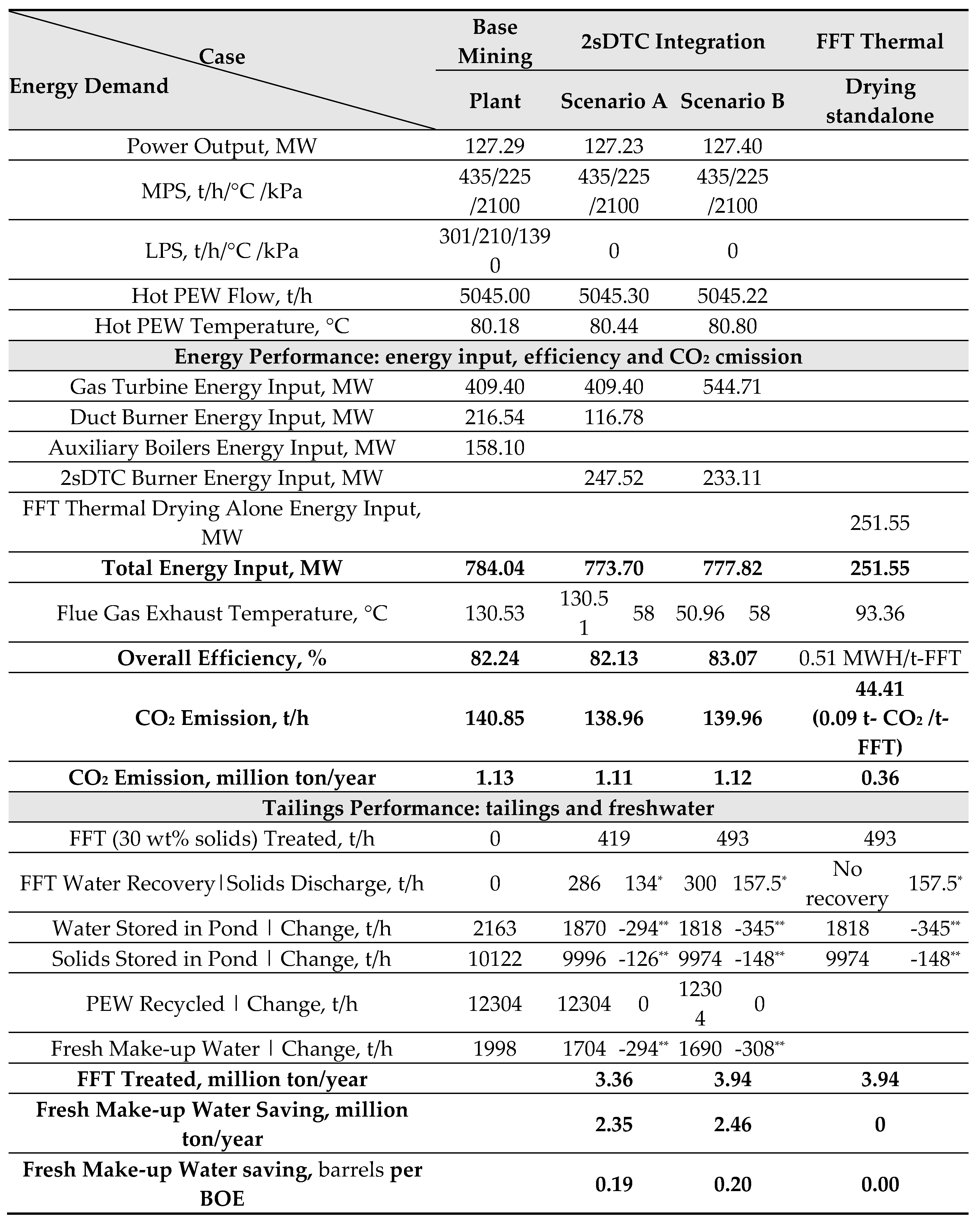
Table 1 provides a concise overview of the simulation outcomes for the base mining plant in Figure 2, integration scenario A in Figure 5 and integration scenario B in Figure 7, as well as an isolated case of FFT thermal drying that handles an equivalent quantity of FFT as Scenario B without heat recovery. It is important to note that oil sands mining operations typically run 24/7. The calculations for annual CO2 emissions and freshwater conservation are established on an operational year comprising 8,000 production hours.
The results show that the integration scenarios A&B require slightly less amount of energy input than the base mining plant to yield the same production of bitumen. The key distinction is the integration scenarios A&B have the capacity to consume FFT, a capability absent in the base mining plant. Notably, Scenario B can manage a larger volume of FFT (493 t/h) compared to Scenario A (419 t/h). In the case of standalone FFT thermal drying, processing one ton of FFT demands 0.51 MWH of energy and emits 0.09 ton of CO2. To treat 493 t/h of FFT, as scenario B does, the standalone FFT thermal drying case would necessitate 251.55 MWH of energy, yielding 44.41 t/h of CO2 or 0.36 million tonnes of CO2 emissions annually. This energy and environmental penalty are circumvented by the integration of the 2sDTC process.
An additional advantage of integration scenarios A&B lies in the potential reduction of freshwater utilization and pond water storage. Per operational year, scenario A can treat 3.36 million tonnes of FFT, while scenario B can handle 3.94 million tonnes. This translates to freshwater savings of 2.35 million tonnes for scenario A and 2.46 million tonnes for scenario B, equivalent to conserving about 0.19~0.2 barrels of freshwater per BOE. Compared to the base mining plant, as depicted in Figure 9, the integration cases exhibit a 2% higher reclaimed water rate, 14.7% lower freshwater usage in scenario A, and 15.4% lower freshwater usage in scenario B. Furthermore, water directed to pond storage is reduced by 13.57% in scenario A and 15.95% in scenario B, contributing to enhanced sustainability.
After bitumen extraction from the ore, residual solids including clays and sands, with the exception of breaker rejects originating from the ore preparation procedure, are typically directed to the tailings pond. A depiction of the solids balance for both the base mining plant and the integration scenarios is provided in Figure 10. Leveraging the production of dry solids via FFT dewatering, the integration scenarios exhibit the potential to curtail solids directed to pond storage by 1.2% for scenario A and 1.4% for scenario B.
The dried solids discharge from the 2sDTC process contains 94 wt% solids at about 93 °C, constitueting a heat loss if no heat recovery means implemented. For landfill purpose, a discharge with 80 wt% solids content is desirable. For the 2sDTC process to produce dried solids dischage containing 20% moisture, the heat loss and water loss will be significant and not desirable. Therefore an optimal approach is blending the 2sDTC dried solids discharge into cold FFT containing 30 wt% solids to achieve 80 wt% solids content. This approach can preserve the thermal enegy performance of the integration meanwhile enhance the capacity of consuming FFT. For instance in scenario B, as shown in Table 2, the 157 t/h of dried solids discharge (94 wt% solids) would require 45 t/h of cold FFT (30 wt% solids) to produce 202 t/h of discharge with 80 wt% solids content for landfill use, thus the capacity of scenario B is enlarged from consuming 493 t/h of FFT to 538 t/h of FFT, a 9% capacity increase.
FFT centrifuge technology has the capability to generate a product with 55 wt% solids content. Utilizing FFT with an initial solids content of 30 wt%, this technology can reduce 1.0 m³ of FFT to approximately 0.45 m³ of cake [23]. When introducing such a concentrated FFT to the 2sDTC process integration, its capacity to consume FFT is expected to be even more pronounced.
Dealing with such a high solids content in FFT will be a great challenge for the design of 2sDTC equipment and system. A critical property of FFT is its viscosity, a parameter that significantly influences its pump-ability. The author conducted viscosity measurements of MFT collected from the mining field at varying solids contents using a Fann viscometer model 35SA. The results revealed that MFT concentrated to ~50 wt% solids could still maintain its pump-ability. However, as the solids-to-water concentration exceeded 55-60 wt%, the viscosity increased dramatically, as shown in Figure 11. Beyond 70 wt% solids, the viscosity value surpassed 1,000,000 (cP) and exceeded the viscometer’s upper limit of measurement, and the mixture resembled a paste (modeling clay). This rapid increase in viscosity would limit the ability to process or dewater MFT and maintain its mobility or pump-ability through conventional methods or equipment. The results of these viscosity measurements validate the simulation’s assumption that the FFT input to the flash dryer can accommodate a solids content up to 50 wt%.
Table 3 shows the capacity enhancement through implementing FFT centrifuge into 2sDTC integration, assuming that the input FFT solids concentration to the 2sDTC process is 50 wt%. When the final discharge is dried solids containing 6 wt% moisture (part 1 in Table 3), the capacity of scenario A is enlarged from consuming 419 t/h of FFT to 1006 t/h of FFT, scenario B from consuming 493 t/h of FFT to 1192 t/h of FFT, a capacity increase of 140% for scenario A and of 142% for scenario B. For comparison, a standalone centrifuge case that produces the FFT containing 50 wt% moisture is listed.
When the final discharge is dried solids containing 20 wt% moisture for landfill (part 2 in Table 3), the capacity of both scenarios is further increased. There is an option of either using FFT containing 30 wt% solids or using FFT containing 50 wt% solids from the centrifuge to blend with the dried discharge (94 % solids) from 2sDTC. When using FFT with 50 wt% solids out of centrifuge for blending, the scenario B has the highest capacity consuming 1487 t/h of FFT or 11.89 million tonnes annually. It transltes into 7.22 million tonnes of freshwater saving per year or equivalent to a reduction of 0.58 barrels per produced BOE. This capacity enhancement incurs no thermal energy penalty but requires additional power to operate centrifuge machinery.
In this simulation, PEW is assumed to be 100% water, though, in reality, there are inevitably very fine solids present. To achieve the production of 105 t/h of MPS for stripping from hot PEW, a flow rate exceeding 105 t/h of hot PEW will be necessary to account for blowdown. The simulation ignores this blowdown, as well as the blowdown from the stage 2 recovery vessel in the 2sDTC process.
The economic feasibility of the 2sDTC process requires assessment. A preliminary estimate suggests that the 2sDTC process, by employing direct contact of different streams, could allow simple tank type equipment setups. Even equipped with burners, tank-type vessels are expected to be less expensive to fabricate, operate and maintain, and may offer economic advantages over conventional setups involving steam boilers and heat exchangers.
4. Conclusion
The two-stage direct thermal contact (2sDTC) process, developed for oil sands surface mining plants, is a rapid approach for dewatering FFT for tailing inventory reductions and freshwater savings. Within the context of this study, implementing a standalone 2sDTC process requires 0.51 MWH of energy and results in the emission of 0.09 ton of CO2 to process one ton of FFT, concentrating from 30 wt% solids to 94 wt% solids. It is crucial to recover the heat carried in steam from FFT evaporation to avoid significant energy loss. Therefore, the successful and optimal application of the 2sDTC process, or any other thermal drying process, hinges on effectively integrating the recovered energy into the surface mining plant without compromising other energy integration efficiencies. Two scenarios of integration are investigated using HYSYS simulations. This simulation-based case study demonstrates the technical feasibility of the integration: over an operational year, the surface mining plant integrated with the 2sDTC process can thermally dry and consume up to 3.94 million tonnes of FFT, discharge dried solids containing 6% moisture and reduce water discharges to ponds by up to 16%. It leads to substantial freshwater savings of up to 2.46 million tonnes per year, equivalent to a reduction of 0.2 barrels per produced BOE. Notably, in 2022, oil sands surface mining in Canada yielded 1618 thousand barrels of oil per day (data from CAPP & AER). The potential for freshwater saving by the 2sDTC process could reach 324 thousand barrels of freshwater per day. Importantly, these advantages incur no additional energy penalty nor CO2 emissions associated with this FFT thermal dewatering. This underscores the capability of the 2sDTC process to enhance the environmental sustainability of oil sands mining operations.
FFT centrifuge technology has the capability to generate a product with 55 wt% solids content. However, this increase in solids content poses a challenge to maintaining FFT mobility or pump-ability through conventional methods or equipment. An experimental investigation was conducted to measure the viscosity of FFT at varying solids contents. The results indicated that FFT concentrated to approximately 50 wt% solids could still maintain pump-ability, validating the simulation’s assumption that the FFT input to the 2sDTC can accommodate a solids content up to 50 wt%.
Taking advantage of this centrifuge concentrated FFT, the capacity of 2sDTC integration is then greatly enhanced. The most substantial capacity enhancement occurs in scenario B, which produces dried solids containing 20 wt% moisture for landfill. In this case, FFT containing 50 wt% solids from the centrifuge is utilized for both the 2sDTC process and blending with the dried discharge (94% solids) from the 2sDTC. In comparison to scenario B without centrifuge concentration, this enhanced scenario can process 11.89 million tonnes of FFT per year (compared to 3.94 million tonnes), saving 7.22 million tonnes of freshwater annually (versus 2.46 million tonnes), or equivalent to a reduction of 0.58 barrels per produced BOE (versus 0.2 barrels per produced BOE). Notably, this capacity enhancement incurs no thermal energy penalty and requires additional power to operate the centrifuge machinery. Given that the surface mining plant typically features a co-gen utility plant, the power needed by the centrifuge machinery could be supplied by the shaft work of a gas turbine to minimize power losses.
Author Contributions
Lijun Wu * : Conceptualization, Methodology, Investigation, Formal analysis, Writing - Original Draft, Ted Herage: Experiment, Investigation, Writing - Review & Editing, Funding acquisition, Quan Zhuang: Conceptualization, Methodology, Bruce Clements: Conceptualization, Methodology, Writing - Review & Editing, Supervision. All authors have read and agreed to the published version of the manuscript.
Funding
The study was funded by Natural Resources Canada’s PERD Oil and Gas Research Program and based on project “Direct Contact Process and Method for Producing Hot Water Using Mature Fine Tailings (MFT) Feedwater”.
Data Availability Statement
Data supporting reported results are available upon request.
Acknowledgments
The authors appreciate the assistance of Nabil Yaghi and Brianna Hataley of CanmetENERGY Ottawa.
Conflicts of Interest
The authors declare no conflict of interest.
References
- Natural Resources Canada, Energy Fact Book 2022-2023, 2022. https://publications.gc.ca/collections/collection_2022/rncan-nrcan/M136-1-2022-eng.pdf (accessed July 20, 2023).
- Oil Sands Magazine (OSM), Process Overview: from the Ground to Your Gas Tank, (2022). https://www.oilsandsmagazine.com/news/2022/4/11/process-overview-bitumen-extraction-dilution-upgrading-refining (accessed September 14, 2022).
- J. Masliyah, Z.J. J. Masliyah, Z.J. Zhou, Z. Xu, J. Czarnecki, H. Hamza, Understanding Water-Based Bitumen Extraction from Athabasca Oil Sands, Can. J. Chem. Eng. 82 (2008) 628–654. [CrossRef]
- Alberta Energy Regulator (AER), Tailings, https://www.aer.ca/providing-information/by-topic/tailings (accessed 14 September 2022).
- Canada’s Oil Sands Innovation Alliance (COSIA), Technical Guide for Fluid Fine Tailings Management, report 2012, page 1-1. https://cosia.ca/node/57.
- Alberta Energy Regulator (AER), State of Fluid Tailings Management for Mineable Oil Sands 2020, report 2021. https://static.aer.ca/prd/documents/reports/2020-State-Fluid-Tailings-Management-Mineable-OilSands.pdf.
- K.A. Clark, D.S. K.A. Clark, D.S. Pasternack, Hot Water Seperation of Bitumen from Alberta Bituminous Sand, Ind. Eng. Chem. 24 (1932) 1410–1416. [CrossRef]
- K.A. Clark, The Hot Water Method for Recovering Bitumen from Bituminous Sand, Report on Sullivan Concentrator, Alberta Research Council, Edmonton, Alberta., 1939.
- S. Roberts, Separating the Sands: Karl Clark and Early Oil Sands Research in Alberta, 2018. https://ir.lib.uwo.ca/etd/5568.
- R.J. Chalaturnyk, J. R.J. Chalaturnyk, J. Don Scott, B. Özüm, MANAGEMENT OF OIL SANDS TAILINGS, Petroleum Science and Technology. 20 (2002) 1025–1046. [CrossRef]
- Alberta Energy Regulator (AER), Oil Sands Mining Water Use Performance, Nonsaline Water Use Intensity, 2022. https://www.aer.ca/protecting-what-matters/holding-industry-accountable/industry-performance/water-use-performance/oil-sands-mining-water-use (accessed July 31, 2023).
- Alberta Energy Regulator (AER), Alberta Energy Outlook, Natural Gas-Statics and Data, 2023. https://www.aer.ca/providing-information/data-and-reports/statistical-reports/st98/natural-gas/production (accessed July 31, 2023).
- U.S. Energy Information Administration - EIA, Carbon Dioxide Emissions Coefficients, https://www.eia.gov/environment/emissions/co2_vol_mass.php (accessed July 31, 2023).
- N. Romaniuk, M. N. Romaniuk, M. Mehranfar, H. Selani, B. Ozum, M.J. Tate, J.D. Scott, Residual bitumen recovery from oil sand tailings with lime, in: Proceedings Tailings and Mine Waste, Vancouver, BC, 2015. [CrossRef]
- Silawat Jeeravipoolvarn, Warren Miller, Don Scott, Louis Kabwe, Ward Wilson, Modeling Effect of Bitumen Extraction Processes on Oil Sands Tailings Ponds, JCEA. 11 ( 2017. [CrossRef]
- S. Arnipally, R. S. Arnipally, R. Burden, B. Ozum, Lime as an Additive for Oil Sands Ore-Water Slurry Based Bitumen Extraction, Tailings Disposal and Fluid Fine Tailings Dewatering Processes, in: Proceedings of the 22nd International Conference on Tailings and Mine Waste, Keystone, Colorado, USA, 2018. https://tailingsandminewaste.com/2018/TMW2018_Proceedings.pdf.
- S. Arnipally, A. S. Arnipally, A. Tang, J.D. Scott, B. Ozum, Reduction of Environmental Impacts of Oil Sands Plants by Implementing Bitumen Extraction and Tailings Disposal Processes using Lime (CaO) Additive, in: Geo Edmonton MOVING FORWARD, Edmonton, AB, Canada, 2018.
- C. Flury, A. C. Flury, A. Afacan, M. Tamiz Bakhtiari, J. Sjoblom, Z. Xu, Effect of Caustic Type on Bitumen Extraction from Canadian Oil Sands, Energy Fuels. 28 (2014) 431–438. [CrossRef]
- P.K.A. Hong, Z. P.K.A. Hong, Z. Cha, X. Zhao, C.-J. Cheng, W. Duyvesteyn, Extraction of bitumen from oil sands with hot water and pressure cycles, Fuel Processing Technology. 106 (2013) 460–467. [CrossRef]
- D.A. Russell, Petroleum Diesel-Assisted Ambient Temperature Aqueous-Nonaqueous Hybrid Bitumen Extraction Process, (2017). [CrossRef]
- Y. Zhu, Y. Lu, Q. Liu, J. Masliyah, Z. Xu, Comprehensive study on cleaner production of heavy oil from Athabasca oil sands using chemical additives in biodiesel-assisted ambient-aqueous bitumen extraction process, Journal of Cleaner Production. 277 (2020) 122940. [CrossRef]
- S. Sleep, J.M. S. Sleep, J.M. McKellar, J.A. Bergerson, H.L. MacLean, Expert assessments of emerging oil sands technologies, Journal of Cleaner Production. 144 (2017) 90–99. [CrossRef]
- BGC Engineering Inc, Oil Sands Tailings Technology Review, Oil Sands Research and Information Network, University of Alberta, School of Energy and the Environment, Edmonton, Alberta. OSRIN Report No. TR-1, 2010. https://era.library.ualberta.ca/communities/e4fdd15f-c21d-4612-a2f7-bfec3fdfc1de/collections/6c42e843-696d-430b-b815-693fbcff36d1 (accessed July 31, 2023).
- J. Sobkowicz, Oil Sands Tailings Technology Deployment Roadmap Project Report – Volume 1: Project Summary | Canada’s Oil Sands Innovation Alliance - COSIA, 2012. https://cosia.ca/node/59 (accessed July 31, 2023).
- J.M. Bonem, G. Kimbal, The MITD process for dealing with MFT, 2nd International oil sands tailings conference, Dec 2-5, 2012, Edmonton, AB, Canada.
- J. Matthews, Fluid Tailings Thermal Drying: More promising than you might think, 7th International oil sands tailings conference, Dec. 4 – 7, 2022, Edmonton, AB, Canada.
- J. McKinley, A. Sellick, R. Dawson, & A. Hyndman, Fluid Fine Tailings Management Methods, 2018. https://cosia.ca/sites/default/files/attachments/FFT%20Management%20June%2026_0.pdf.
- Dedert Corporation, Flash Dryers & Their Usage: A Comprehensive Look, 2023. https://dedert.com/flash-dryers/overview/ (accessed August 2, 2023).
- M.A. da Silva, F. M.A. da Silva, F. Lopes Motta, J.B.P. Soares, Recovery of residual bitumen, dewatering, and consolidation of oil sands tailings with poly(acrylamide-co-lauric acid), Minerals Engineering. 174 (2021) 107248. [CrossRef]
Figure 1.
Oil sands tailings pond: PEW and FFT (including TFT and MFT) formation.
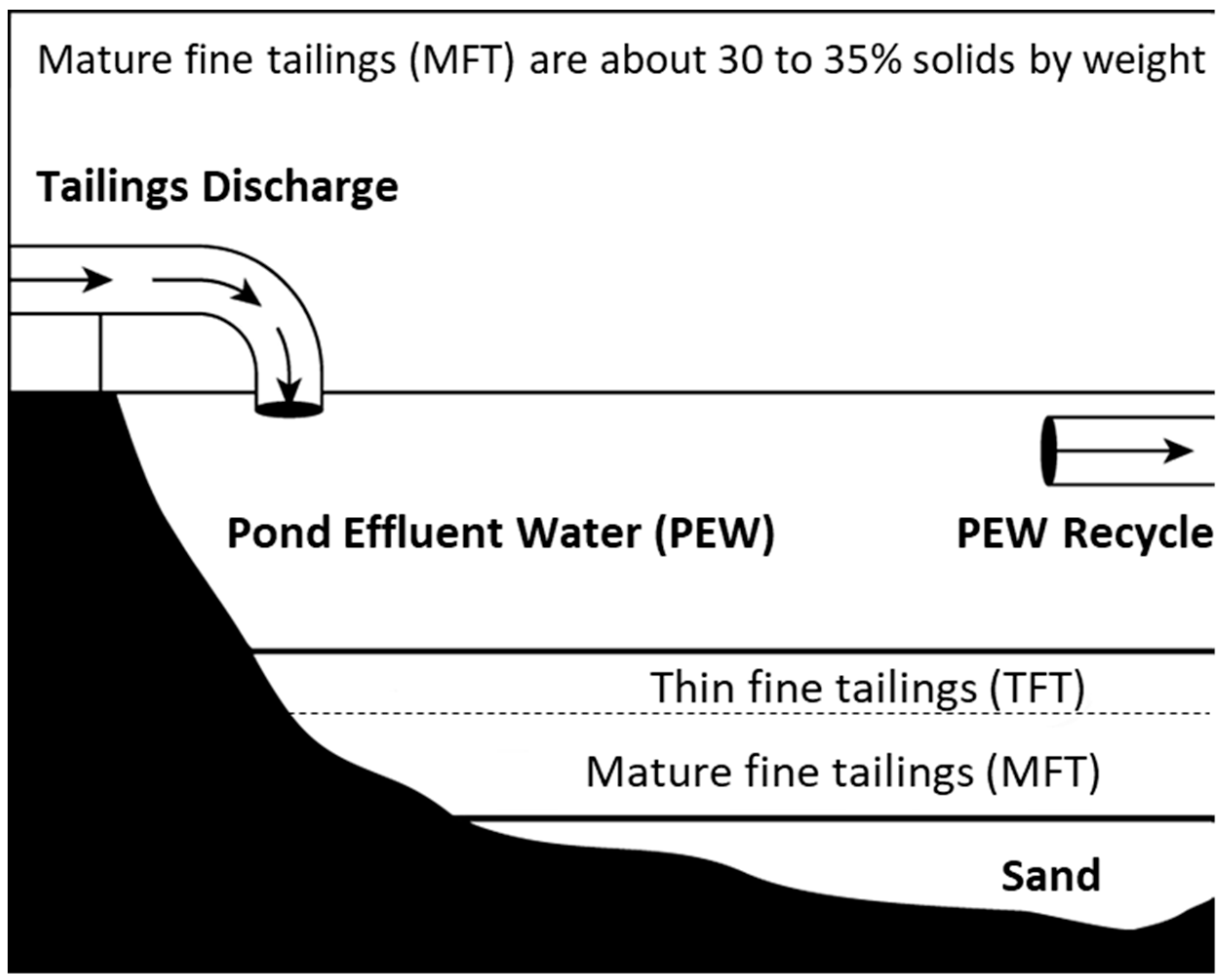
Figure 2.
An example oil sands bitumen extraction plant with material balance, the base plant for simulation.
Figure 2.
An example oil sands bitumen extraction plant with material balance, the base plant for simulation.
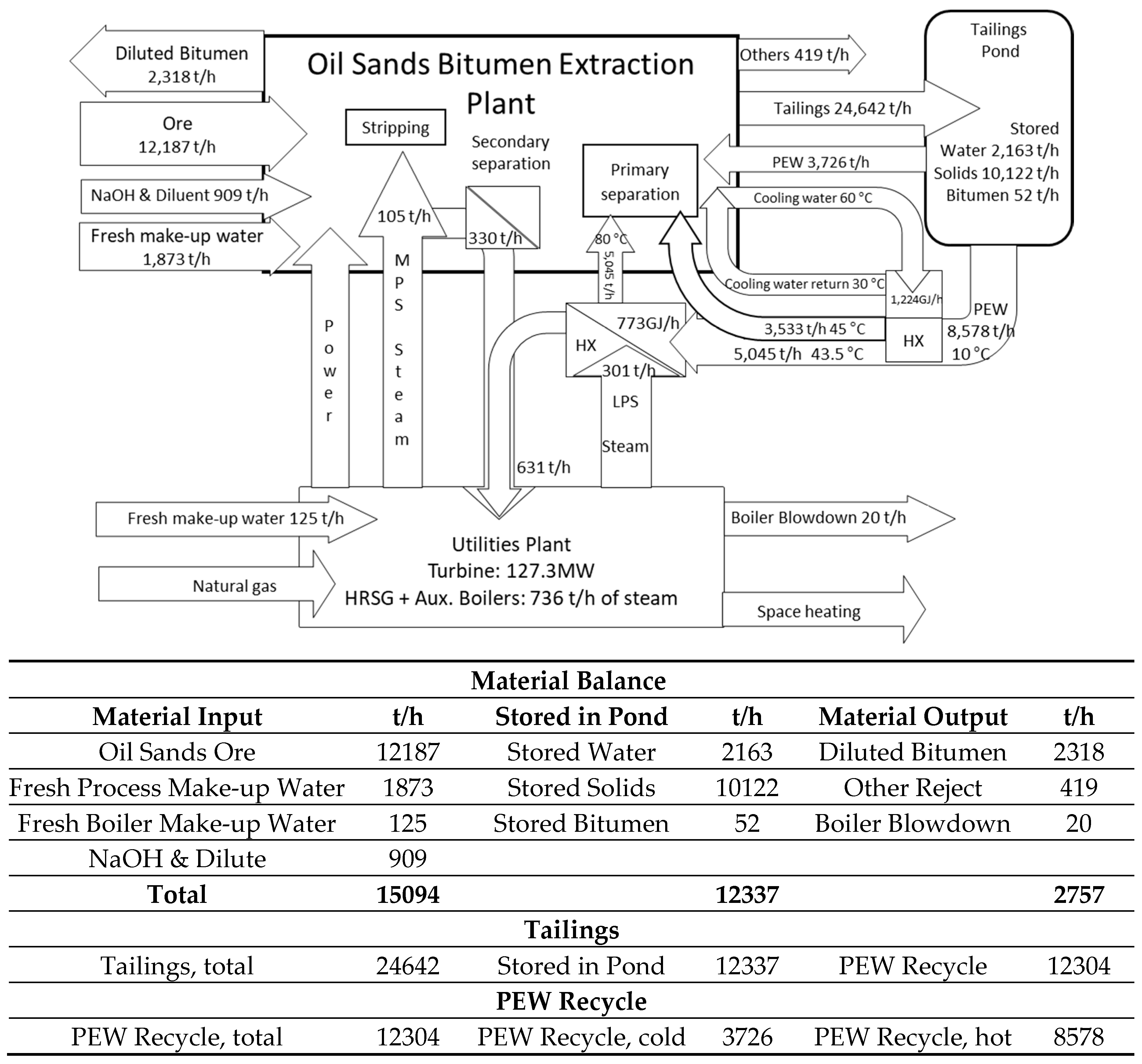
Figure 3.
Base utility plant for bitumen extraction - diagram and energy balance.
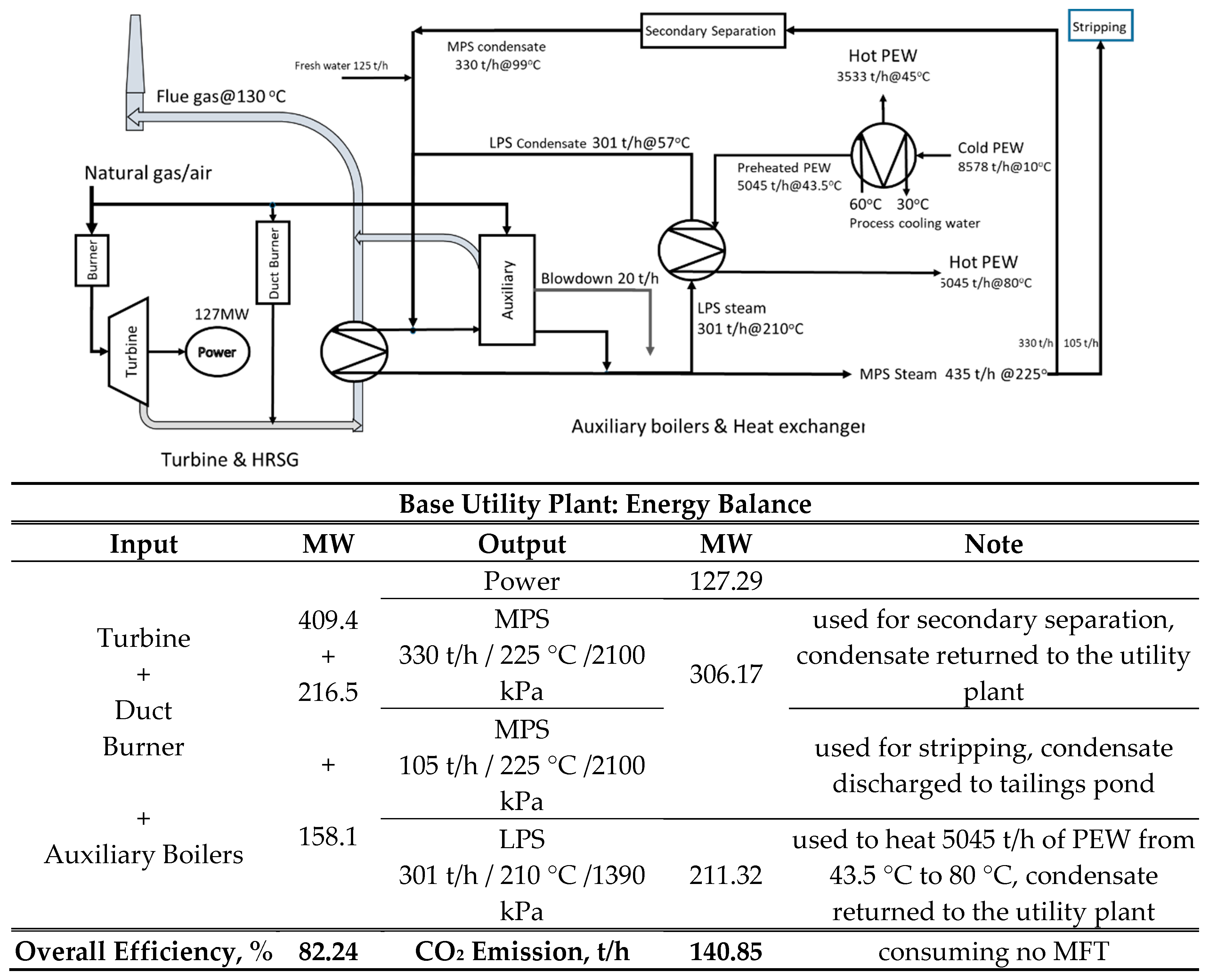
Figure 4.
FFT thermal drying 2sDTC process.
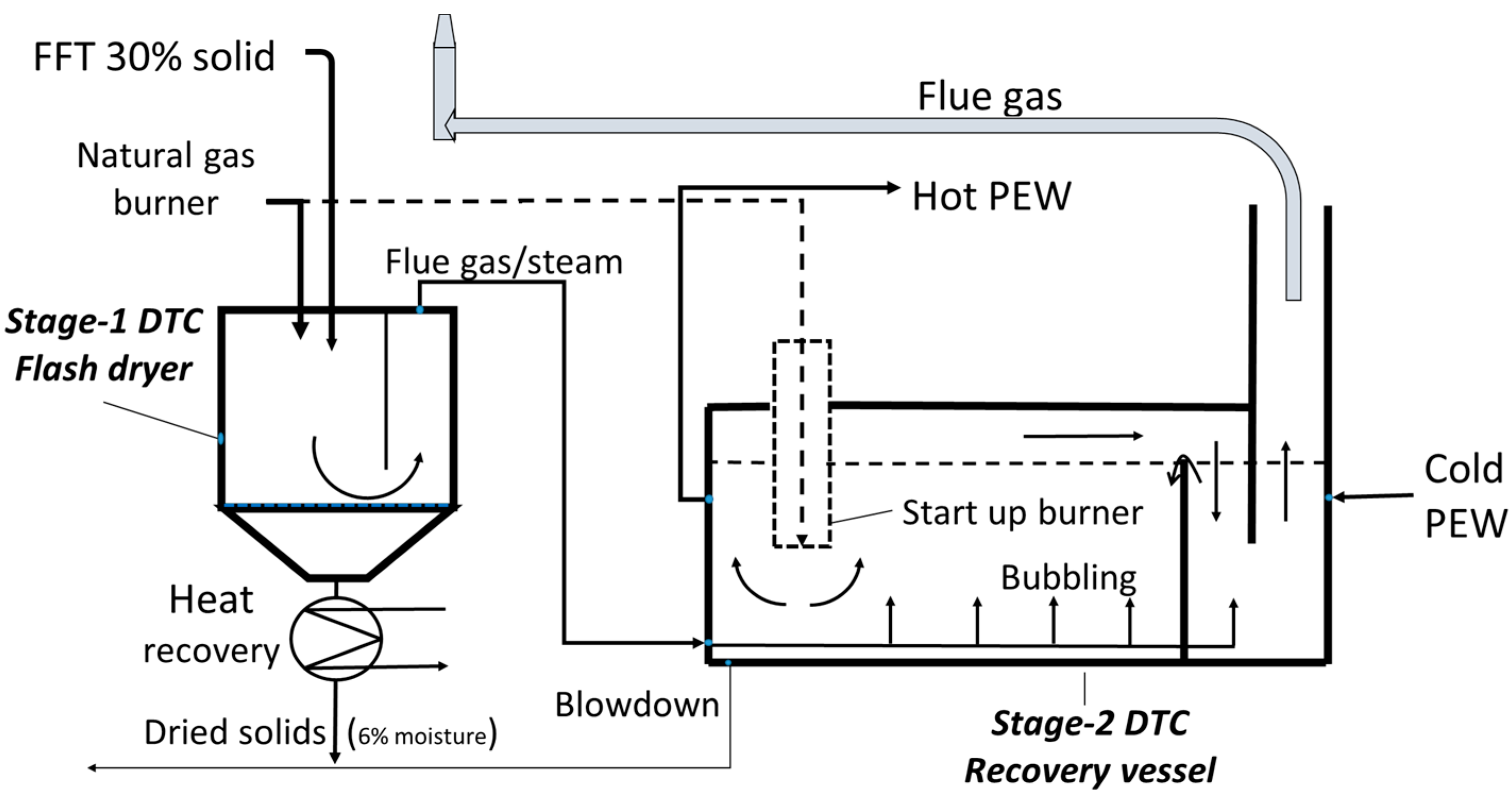
Figure 5.
The configuration of integration Scenario A.
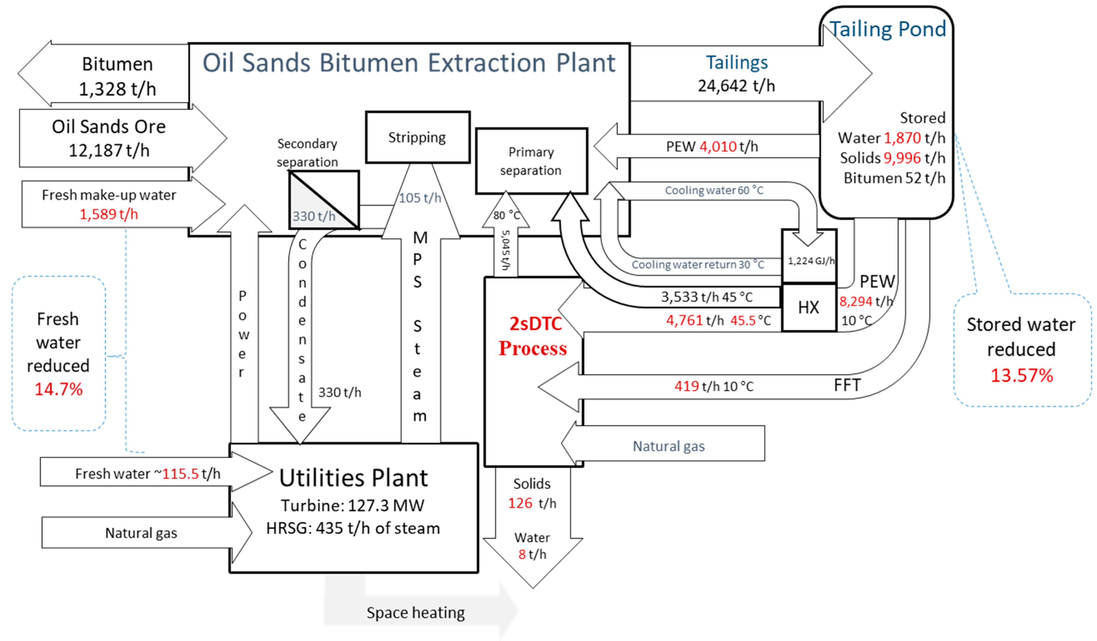
Figure 6.
Energy balance and Performance of integration scenario A.
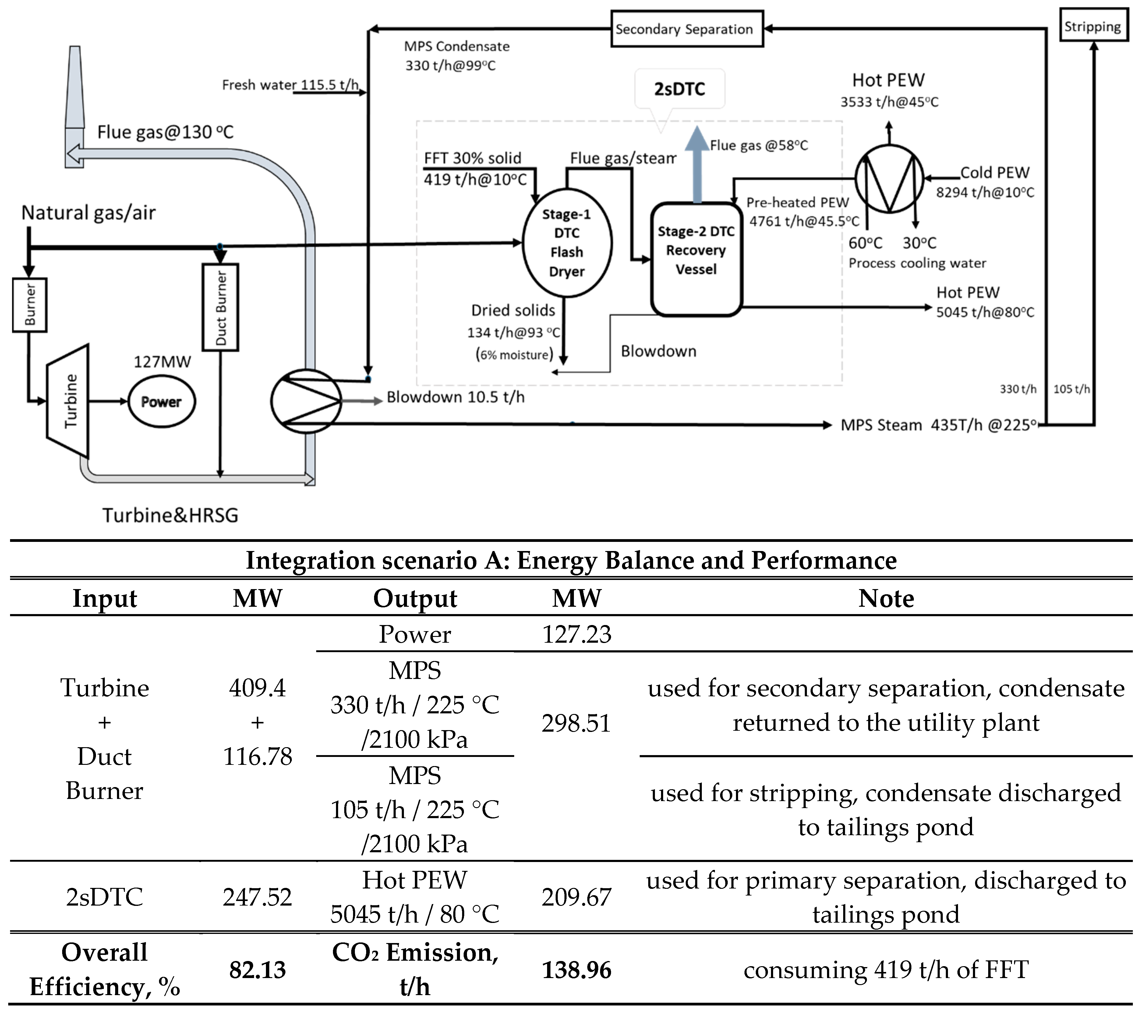
Figure 7.
Configuration of integration Scenario B.
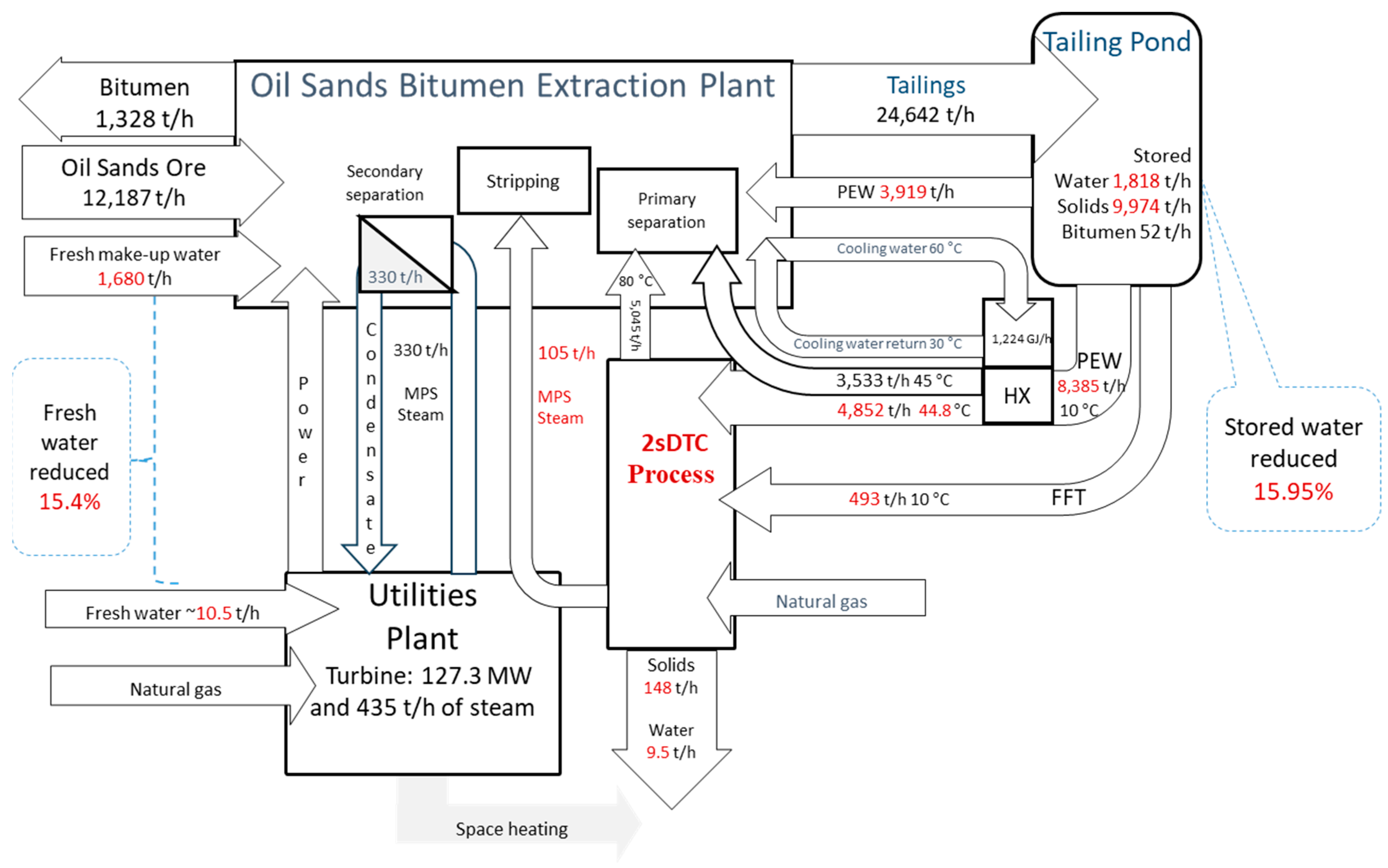
Figure 8.
Performance of integration Scenario B.
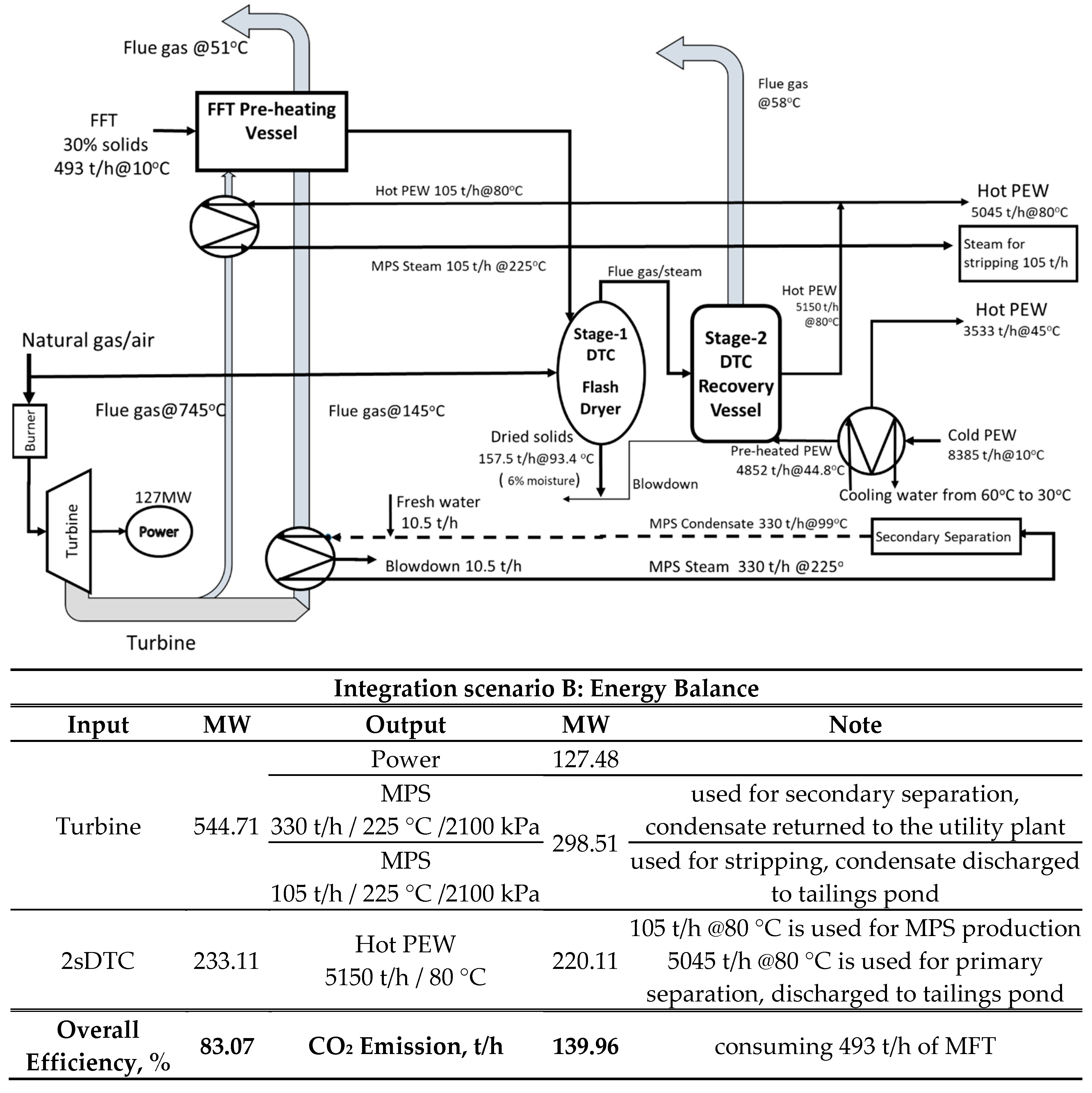
Figure 9.
Comparison between the base mining plant and the integration scenarios: fresh make-up water, reclaimed water, and water to pond storage.
Figure 9.
Comparison between the base mining plant and the integration scenarios: fresh make-up water, reclaimed water, and water to pond storage.
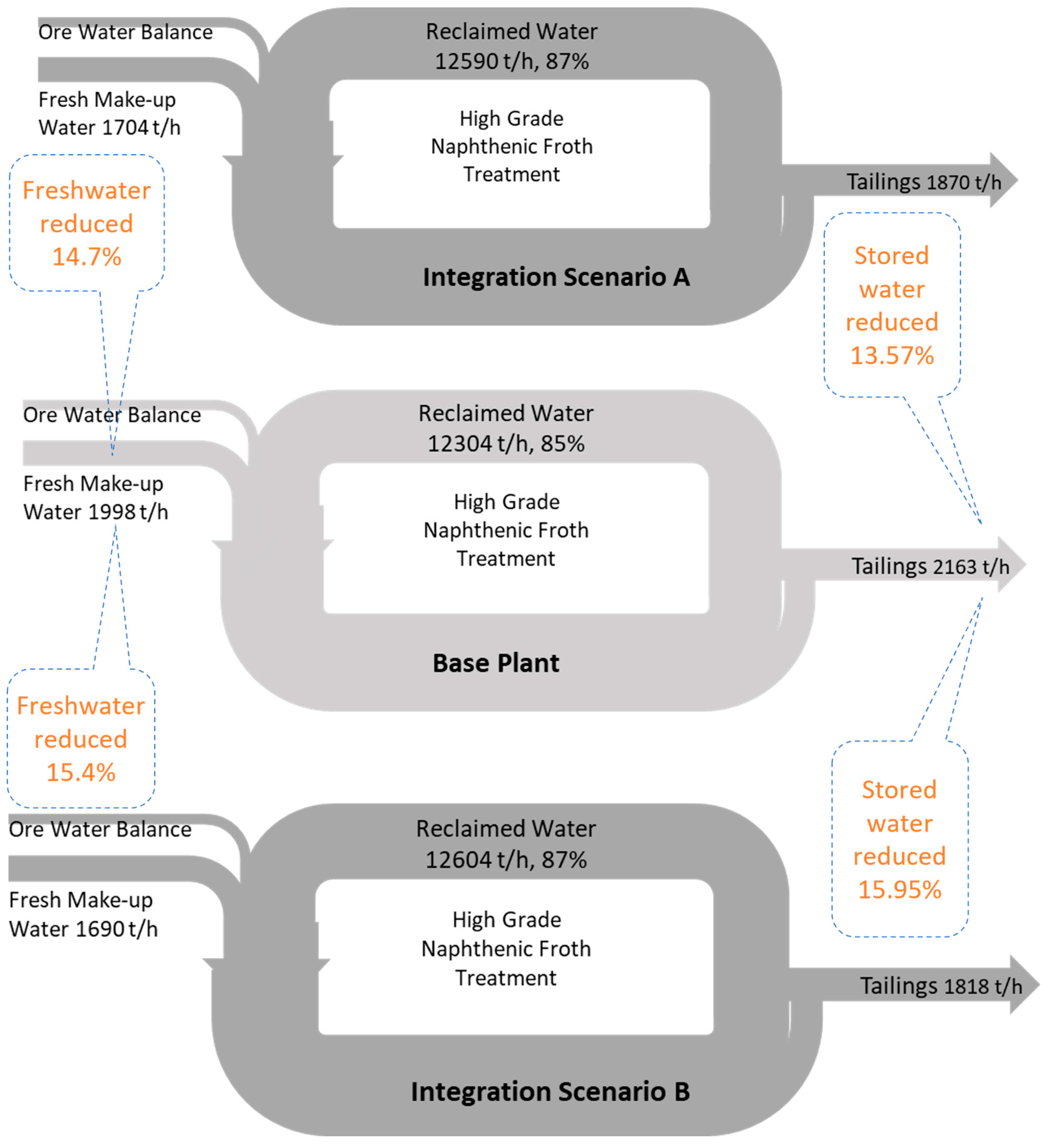
Figure 10.
Comparison between base plant and integration scenarios: solids to pond storage.
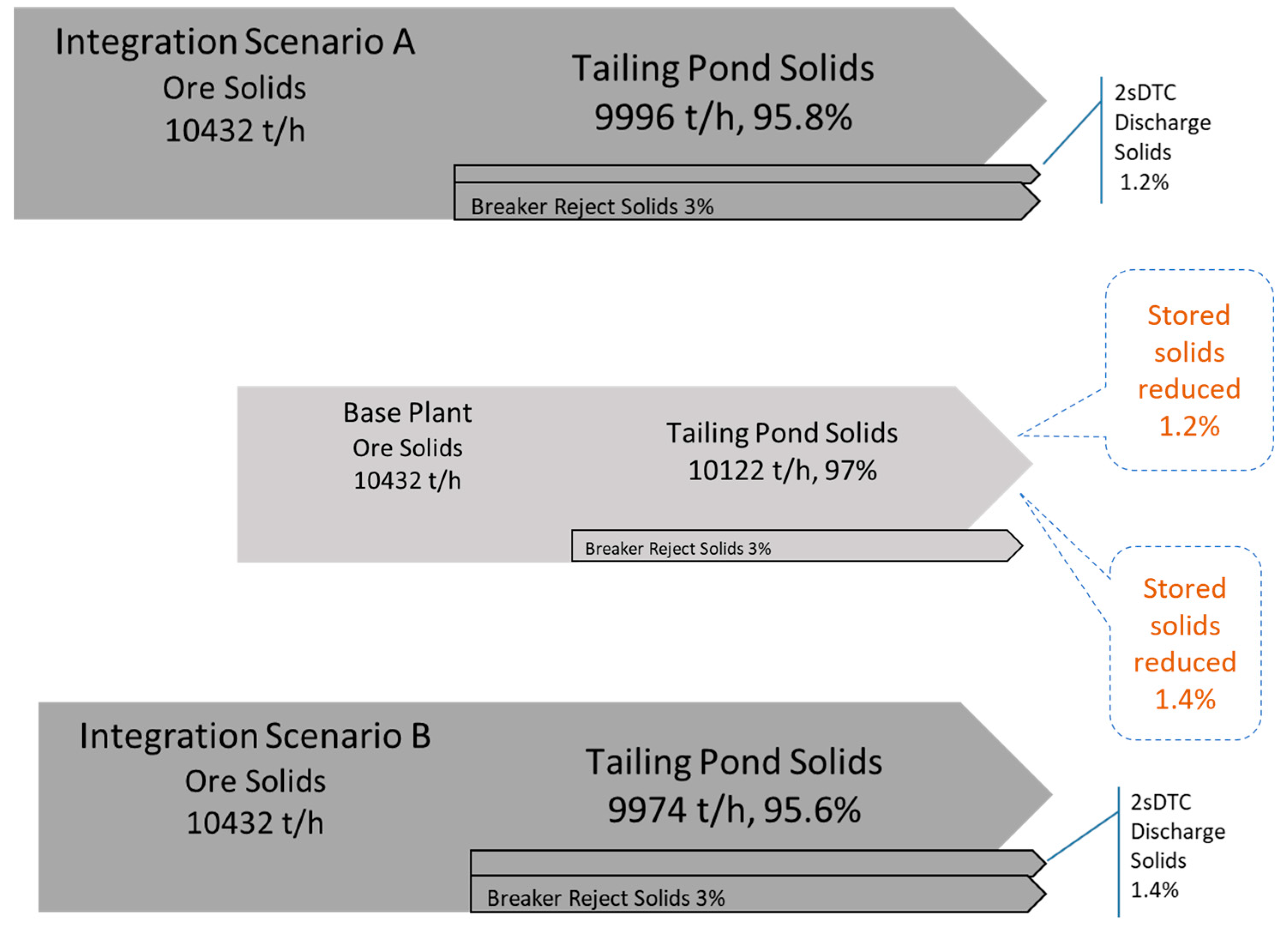
Figure 11.
MFT viscosities at different solids contents and concentration of solids at 25 wt%, 50 wt% and 70 wt%: pump-ability could be maintained at ~50 wt% solids and less.
Figure 11.
MFT viscosities at different solids contents and concentration of solids at 25 wt%, 50 wt% and 70 wt%: pump-ability could be maintained at ~50 wt% solids and less.
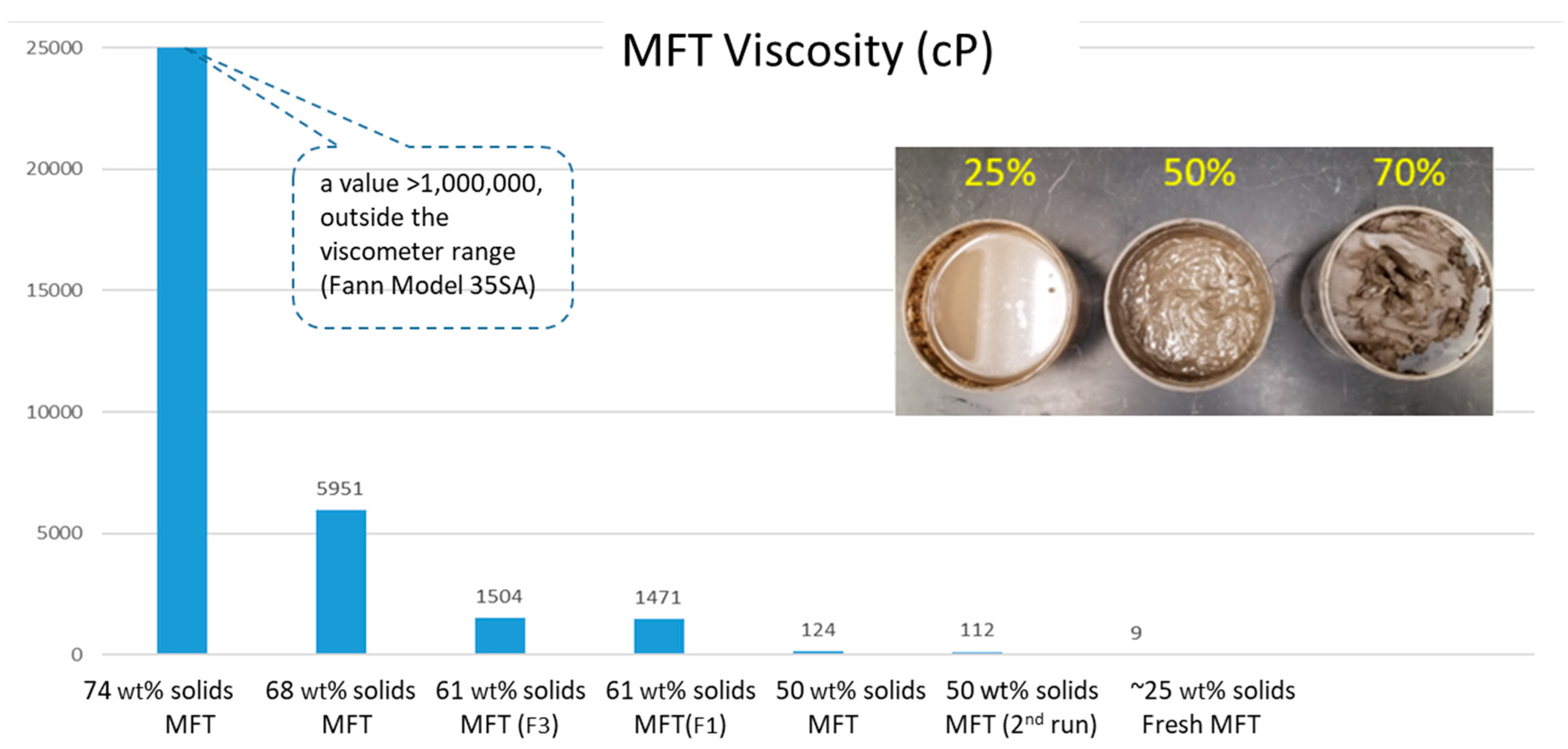

Table 1.
Simulation results of the base mining plant, 2sDTC scenarios A&B and s tandalone FFT thermal drying.
Table 1.
Simulation results of the base mining plant, 2sDTC scenarios A&B and s tandalone FFT thermal drying.
Note: *dried solids with 6% moisture, **a (-) sign is a reduction from base mining plant.
Table 2.
Blended Solids (20%moisture) for landfill.
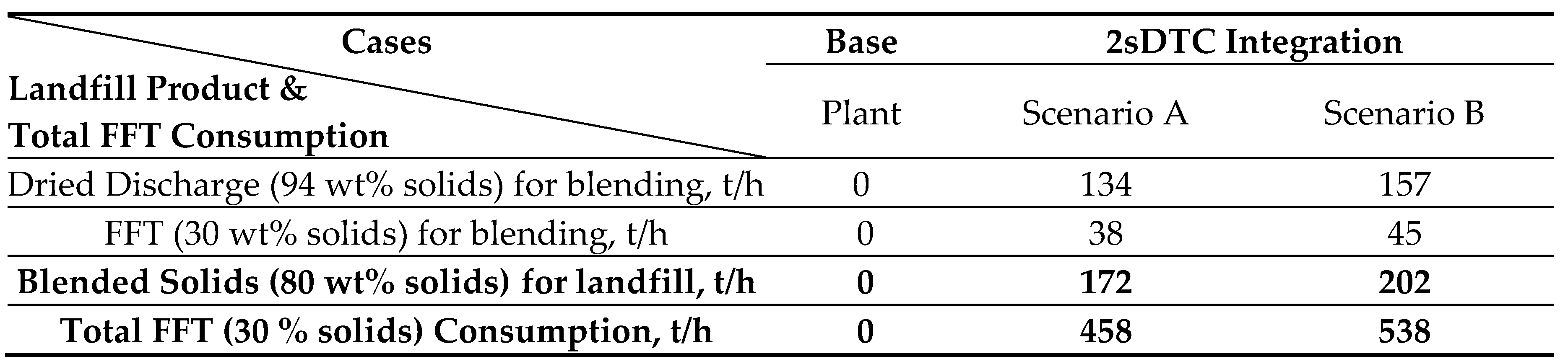
Table 3.
Implementation of Centrifuge in 2sDTC Integration.
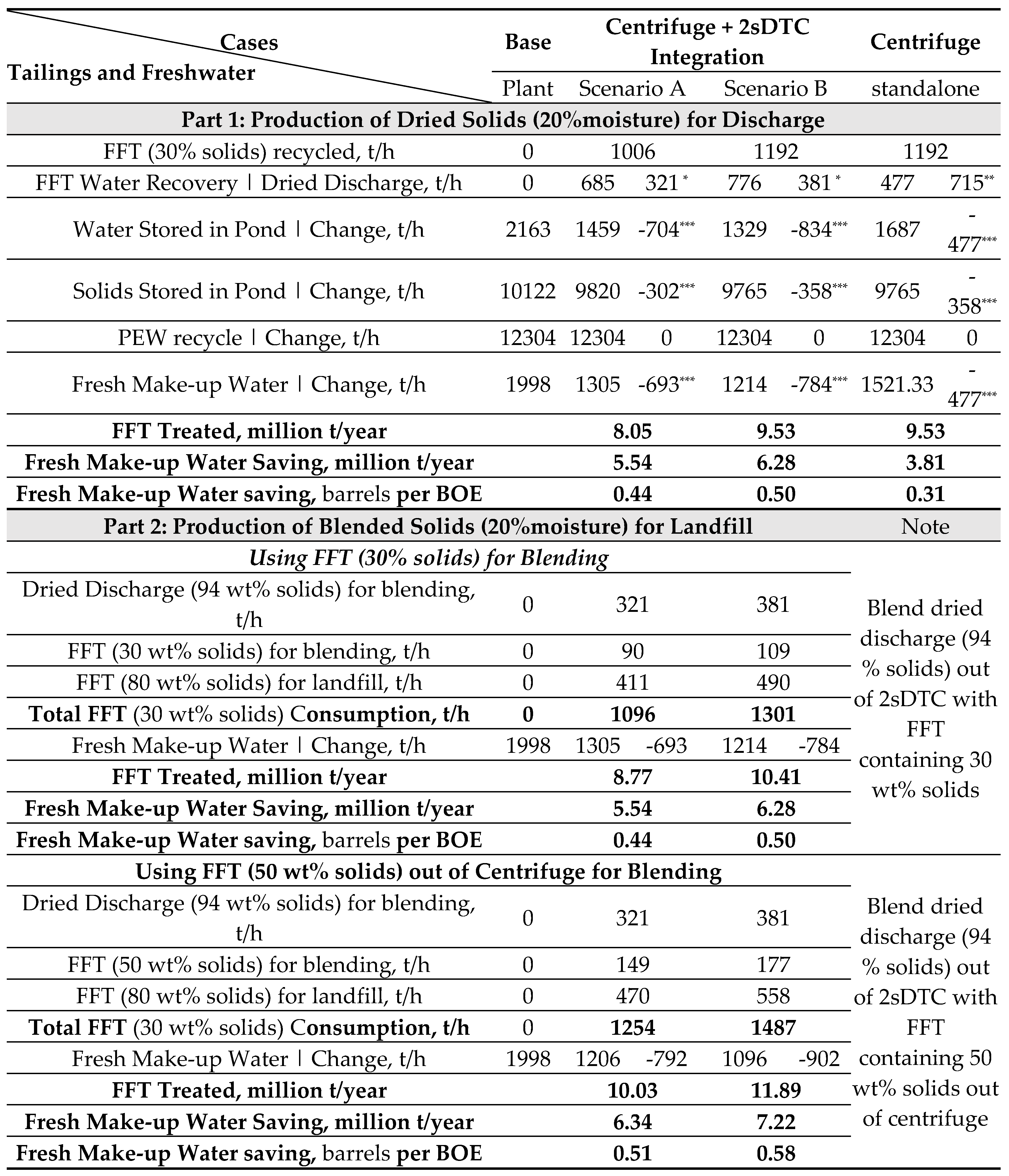
Note: *dried solids with 6% moisture, **dried solids with 50% moisture, ***a (-) sign is a reduction from base plant.
Disclaimer/Publisher’s Note: The statements, opinions and data contained in all publications are solely those of the individual author(s) and contributor(s) and not of MDPI and/or the editor(s). MDPI and/or the editor(s) disclaim responsibility for any injury to people or property resulting from any ideas, methods, instructions or products referred to in the content. |
© 2023 by the authors. Licensee MDPI, Basel, Switzerland. This article is an open access article distributed under the terms and conditions of the Creative Commons Attribution (CC BY) license (http://creativecommons.org/licenses/by/4.0/).
Copyright: This open access article is published under a Creative Commons CC BY 4.0 license, which permit the free download, distribution, and reuse, provided that the author and preprint are cited in any reuse.


