Submitted:
30 November 2023
Posted:
30 November 2023
You are already at the latest version
Abstract
Nowadays, the increasingly serious environmental pollution and energy problems urgently require internal combustion engine-based transportation vehicles to upgrade or replace, so the new energy transportation vehicles based on hybrid power and fuel cells have gradually stepped on the stage and continue to innovate. The shipping industry is one of the main sources of global greenhouse gas emissions. The development of clean energy ships represented by fuel cells has attracted wide attention. Fuel cell has the advantages of clean, pollution-free and low noise, but it has some disadvantages such as insufficient dynamic response performance and fast performance decay. Limited by the characteristics of a single energy source, a variety of energy sources and bidirectional DC converters are usually mixed together to form a hybrid ship to improve the flexibility, stability and economy of the ship, and enhance its adaptability to complex sea conditions through the reconfiguration of power system energy. Taking fuel cell ferry "FCS Alsterwasser" as the research object, this study proposed an improved equivalent minimum hydrogen consumption energy management strategy based on fuzzy logic control. First, the power system of the modified mother ship was simulated, and a hybrid power system including fuel cell, lithium iron phosphate battery and supercapacitor was proposed. Then, the dynamic system simulation model and double closed loop PI control model are established in MATLAB/Simulink, and the reliability of the model is verified by the simulation analysis of charge and discharge characteristics. Then, the feasibility of the proposed method is demonstrated by designing simulation experiments based on typical working conditions of the mother ship. The simulation results show that under the premise of meeting the load requirements, the control strategy designed in this paper has a better optimization effect than the S-type penalty function in terms of lithium battery power, lithium battery SOC, bus voltage stability and equivalent hydrogen consumption, which improves the stability and economy of the power system, and has certain engineering practical value.
Keywords:
fuel cell
; hybrid energy storage system
; energy management strategy
; fuzzy logic control
; equivalent minimum hydrogen consumption
1. Introduction
Compared with traditional ships, hybrid ships have great development potential and broad application prospects. First of all, hybrid ships use clean energy and renewable energy, which significantly reduces the emission of harmful gases, helps to mitigate global climate change and improve air quality, and has important environmental significance; secondly, the use of natural resources for energy replenishment instead of traditional fossil fuels not only reduces the cost, but also has strong adaptability, and can obtain better navigation results in complex waters and marine conditions; finally, the Hybrid ships have great potential, through technological innovation and intelligent control can improve the efficiency of energy utilization, reduce ship energy consumption, and realize the win-win situation of sustainable development and economic benefits.
A hybrid energy storage system (HESS) has the function of shaving peaks and filling valleys, compensating for sudden changes in operating conditions, and improving power quality. According to the difference of the principle of converting into electric energy, it can be divided into mechanical, electrochemical and electromagnetic energy storage, comprehensively considering the factors of cycle life, energy density, reliability, and configuration cost, etc., to maintain the busbar voltage in the safety margin [1], and at the same time, to meet the demand of continuous power supply of the ship, the energy-type and power-type energy storage is mixed to form the HESS, and the experts at home and abroad have focused on the research of the composite energy storage technology constituted by the lithium batteries/supercapacitors in recent years. In recent years, domestic and foreign experts have focused on the research of composite energy storage technology composed of lithium batteries/supercapacitors.
The load demand of hybrid ships cannot be satisfied by the accumulation of power sources alone, and reasonable energy management strategies need to be designed to strain the complex working conditions while taking into account the service life of the equipment [2,3]. In the past, according to the degree of hybridization, they were divided into switching control strategies and power-following strategies [4]. Current energy management strategies are mainly based on rules, optimization, and artificial intelligence algorithms.
Rule-based energy management strategies are classified into deterministic and fuzzy rules. Han et al [5] proposed a strategy to continuously adjust the battery SOC for power allocation based on typical working conditions, which reduces the hydrogen consumption of the fuel cell and maximizes the efficiency of the system compared with the traditional load-tracking control; Zou et al [6] designed a charging and discharging control strategy for the SOC of the energy storage element to avoid overcharging and over-discharging of the energy storage system. discharging, but the working condition setting is relatively single and the universality of the control strategy cannot be verified; Sun [7] proposed a strategy based on fuzzy control + dynamic coordination, which improves the gas engine efficiency and reduces the system response time for the gas-electric hybrid power system of an inland waterway tugboat. The setting of both deterministic and fuzzy rules needs to be based on expert experience, which makes it difficult to achieve global optimization and has great limitations.
Optimization-based energy management strategies are divided into real-time optimization and global optimization for the optimization problem to formulate the function of optimization objectives and constraints, and to optimize the power allocation of multiple energy sources to operate at the best operating point. The real-time optimization strategy is based on the real-time state parameters of the ship to carry out online control, so that the performance indexes reach the real-time optimum, usually there is an equivalent consumption minimization strategy (ECMS), model predictive control (MPC), and robust control (RC), which can be used to optimize the performance of the ship. robust control (RC), Hu Dongliang [8] used equivalent energy minimization consumption as the objective function and sailing direction and time as the constraints, and used the whale optimization algorithm for dynamic optimization, and the simulation results showed the reduction of the ship's energy consumption. The global optimization strategy needs to be optimized based on the ship's static historical data and known sailing conditions, and the common ones are dynamic programming (DP), genetic algorithm (GA), and particle swarm optimization (PSO), as well as the algorithm variants. Zhang et al [9] decoupled the optimization problem to obtain the corresponding solution, then used the non-dominated sorting-based genetics algorithm II (NSGA-II) to find the Pareto frontier, and finally used fuzzy decision-making to obtain the optimal solution. Due to the limitation of a single intelligent optimization algorithm in searching time and space, in recent years, multiple algorithms have often improved or fused to achieve the optimal solution, but the amount of computation and time consumption also increased accordingly.
Energy management strategies based on artificial intelligence algorithms mainly utilize machine learning, deep learning, and deep reinforcement learning algorithms to control each power source. wu et al [10] applied deep Q-learning (DQL) algorithms to the energy management problem of a parallel electric vehicle, and the results showed that it was better than the Q-learning method in terms of training time and convergence rate. However, since this strategy is still in its infancy, the theory still needs to be verified by a large number of simulation experiments. There are advantages and disadvantages of each method, and different methods can be synergized in order to achieve better control results.
The first section of this paper provides a brief overview of the background and significance of the research on new energy ships, the development of energy storage technology and the current status of energy management strategies, and the remaining sections are structured as follows; the second section designs the topology of the composite energy storage system and models the important components; the third section introduces the transient optimization strategy and designs the energy management strategy in this paper, i.e., the fuzzy control-based equivalent minimum hydrogen consumption strategy, which is characterized as follows Using fuzzy logic control to adaptively adjust the equivalent factor of the hydrogen consumption model to realize the power allocation of the composite energy storage system; Section IV introduces the typical working conditions and optimization model of this paper and designs the corresponding simulation experiments; Section V validates the proposed method through the simulation model, and the results of the simulation experiments are compared and analyzed and discussed.
2. Power System Modeling and Simulation
2.1. Topology Design
The composite energy storage topology determines its energy transfer efficiency, control strategy, configuration cost, etc. Currently, there are three main composite energy storage topologies applied to the marine sector: passive, active, and semi-active [11]. Passive topology in the lithium battery and supercapacitor directly connected in parallel, through the inverter to the load power supply, this architecture is mainly used in the early demonstration of lithium battery/supercapacitor composed of composite energy storage system than the performance advantages of pure battery [12,13], is now less used; semi-active topology has a component controlled by the DC/DC converter, the other party passively bear the load power, is the current use of the most widely used topology configuration [The lithium battery pack is directly connected to the load part, which is easily affected by the high rate of current impact and affects its service life, while the supercapacitor is directly connected to the load, which needs to bear the peak power and improve the capacity, or else the utilization rate is low; the active topology can be classified into series and parallel based on the different structures, and the series architecture consists of a DC/DC converter connected to the DC bus, and the other connected to the energy storage element, but in the case of constant current loads, it is not used anymore. The series architecture consists of one DC/DC converter connected to the DC bus and another one connected to the energy storage element, but it is difficult to realize the balance between the units under constant current load; the parallel architecture consists of two DC/DC converters connected to two energy storage elements, which has a high control accuracy and includes the advantages of other structures, but it is the most difficult to control and the system efficiency is low. Considering the actual use of the ship, this paper chooses the battery semi-active topology, i.e., the battery is connected to the DC/DC converter, and the supercapacitor is directly connected to the DC bus. The topology of the energy storage system in this paper is shown in Figure 1:
2.2. Modeling and Simulation
The fuel cell is a complex nonlinear system with a large number of parameters and a complex dependency relationship between them, so it is necessary to establish a corresponding model according to the specific problem. In the design of a hybrid energy management strategy, the complex internal physicochemical reaction process can be ignored, and it is only necessary to summarize the historical data, repeatedly correct the parameters, and obtain the empirical formula to reflect the output characteristics of the fuel cell, i.e., empirical (analytical) modeling. In this paper, the proton exchange membrane model proposed by [16,17] is cited, and the concentration polarization voltage loss is not considered. The output voltage of the fuel cell is shown in Eq. 1:
where is the open-circuit voltage of the fuel cell, V; is the activation voltage loss, V; and is the ohmic voltage loss, V, respectively, as shown in Eqs. 2-4:
where is the Tafel slope, is the output current of the fuel cell, A; is the exchange current, A; is the response time of the fuel cell, s; is the internal resistance of the fuel cell, Ω; is the Laplace operator; is the voltage constant; and is the potential of the fuel cell, V, shown in Equation 5:
where is the temperature, K; and are the inlet pressures of hydrogen and oxygen, respectively, MPa; is the Faraday constant and is the ideal gas constant.
The charging and discharging voltages of the battery are shown by Equation 6-7 according to the equivalent circuit model proposed in the literature [18,19,20]:
where is the constant battery voltage, V; is the battery polarization resistance, Ω; is the maximum capacity of the battery, Ah; is the dynamic current of the battery, A; is the low-frequency dynamic current of the battery, A; is the exponential voltage coefficient of the battery, V; is the exponential capacity coefficient, Ah-1; is the unit time step.
The output voltage of the supercapacitor is shown by equation 8 according to the literature [21]:
where is the number of supercapacitors in series; is the number of supercapacitors in parallel; is the number of supercapacitor electrode layers; is the material dielectric constant; is the vacuum dielectric constant; is the interfacial area between the electrodes and the electrolyte, m2; is the electric charge, C; is the radius of the molecule, nm; is the molar concentration, mol/m³; is the internal resistance of the supercapacitor, Ω; is the supercapacitor current, A.
In this paper, a simple, reliable, and energy-efficient half-bridge bi-directional DC/DC converter is selected, and its main structure is shown in Figure 2 below:
This half-bridge structure is mainly composed of capacitor C, inductor L, resistor R, and IGBT transistor. Boost or buck mode can be selected as per the requirement. Since there is a lag between the response of the power supply system and the input from the load, this lag can lead to response interruptions and voltage fluctuations [22], which is undesirable in the case of electric motor power supply [23] and can be avoided by limiting the slope of the optimal power input from the control strategy [24]. The reference power of the fuel cell is divided by the voltage to obtain its reference current, and the difference between the reference current and the measured current is regulated by the PI to determine the duty cycle of the DC/DC converter.
Boost mode: Transistor conducts, capacitor automatically releases power to ensure that the bus voltage is stable, and the other voltage stores power in inductor L during operation. When is disconnected, inductor L releases the stored power and supplies bus and capacitor together with . The duty cycle can be found by the following equation 9.
where is the duty cycle, is a switching cycle, and is the conduction time of during a switching cycle. In the buck mode, the variation of voltage with the duty cycle is shown in Eq. 10 as follows.
Buck mode: Unlike the boost mode, transistor operates continuously in the disconnected state. When is on, the high-voltage side stores the electrical energy in inductor L to provide electrical energy to the low-voltage side . When is off, diode turns on, the inductor L releases the stored electrical energy to the low-voltage side . When is disconnected, diode conducts and inductor L releases the stored electrical energy to the high voltage side . The voltage relationship in buck mode is shown in Equation 11:
3. Mathematical Modeling of Optimization Problems
3.1. Fundamental Principle
Compared with the global optimization strategy, which needs to predict all the working conditions of the ship's sailing cycle and is limited by the difference between different ship types and the uncertainty of real-time operation, the real-time optimization strategy takes into account the optimal working point of each power source and evaluates and regulates the current optimal working mode according to the real-time working condition information.
ECMS is a strategy that calculates the equivalence factor based on the battery SOC and the diesel engine operating state, and converts the output power of the energy storage element to the equivalent fuel consumption, so as to minimize the sum of the equivalent fuel consumption of the energy storage element and the actual fuel consumption of the diesel engine, and the equivalent minimum hydrogen consumption strategy is derived based on this, so as to minimize the sum of the hydrogen consumption of the energy storage element and the fuel cell.
Since the energy stored in the fuel cell power generation will be consumed at some time in the future, thus reducing the hydrogen consumption of the fuel cell, the equivalent minimum hydrogen consumption strategy is based on this, to establish the equivalence between the battery, supercapacitor electric energy consumption and fuel cell hydrogen consumption, to unify all the energy consumption into the consumption of hydrogen, and then to obtain the equivalent hydrogen consumption at each transient time. The equivalent hydrogen consumption at each instant is taken as the optimization target of the control strategy, and the energy allocation of the power system is optimized and adjusted in real-time, so that the minimum equivalent hydrogen consumption can be achieved in each control cycle, and the equivalent minimum hydrogen consumption under the complete working condition is finally obtained. When the value of battery SOC is higher, the cost of battery power is smaller, the control strategy should be more inclined to consume battery power to meet the power demand, so the equivalence factor decreases with the increase of battery SOC, and vice versa, when the value of battery SOC is smaller, the cost of battery power is higher, and the control strategy is more inclined to fuel cell to provide the power demand.
3.2. Strategic Design
The calculation of equivalent hydrogen consumption can be shown according to equation 12:
Where is the hydrogen consumption of the fuel cell, and are the equivalent hydrogen consumption of the Li-ion battery and supercapacitor, respectively, and and are the equivalence factors of the two. and are the equivalence factors of the two, and the SOC of the energy storage device can be controlled by adjusting the size of the equivalence factor in real time. because the purpose of the supercapacitor is to cope with the peak of the demanded power under high-frequency working conditions to protect the service life of the fuel cell and the Li-ion battery, and its contribution is negligible compared to that of the other two is minimal and negligible, therefore, this paper chooses to use the PI controller to detect the supercapacitor SOC change, which is adjusted and added to the equivalent power consumption of the lithium battery. Therefore, Eq. 12 can be modified to Eq. 13:
The hydrogen consumption of the fuel cell is given by the following equation 14:
Where is the volumetric flow rate of hydrogen, g/s, is the pressure at the anode, which is designed to be 1.16 kpa in this paper, is the molar mass of hydrogen, g/mol, is the molar gas constant, and is the reaction temperature, which is designed to be 318 K in this paper.
The equivalent hydrogen consumption of a lithium battery is given by equation 15 below:
Where is the real-time power of the Li-ion battery, is the average value of hydrogen consumption of the fuel cell, is the average power of the fuel cell, and represent the charging and discharging efficiency, respectively, and and are the average efficiencies of charging and discharging, which is designed to be 0.8 in this paper, and ≥ 0 indicates that the Li-ion battery is being discharged. <0 indicates that the Li-ion battery is charging. The charging and discharging efficiency is obtained from Eq. 16:
where and are the internal resistance of the battery during charging and discharging, respectively, which is designed as a constant value of in this paper.
For the evaluation of lithium battery loss, it is derived from the following equation 17:
where represents the magnitude of the charging and discharging power of the battery at the moment ; T is the complete time of a typical round of working conditions; and is the rated capacity of the battery pack.
3.3. Optimization Model
When solving the optimization problem, the optimization variables need to set constraints according to the actual situation, and the constraints set in this paper are as follows:
(1) Energy storage element charge state constraint
Lithium batteries and supercapacitors should not be overcharged and over-discharged, otherwise, the internal aging of the components will accelerate, which will seriously affect the service life, so it is necessary to set a reasonable range, as shown in Equation 18.
(2) Energy constraint
The total energy output of the composite energy storage system needs to satisfy the load demand as shown in Eq. 19.
(3) Supercapacitor voltage constraint
The voltage of the supercapacitor determines the size of its energy storage and needs to satisfy the voltage constraints, as shown in Eq. 20.
(4) Instantaneous power balance constraint
The instantaneous power of the power system needs to meet the power demand of the ship to ensure that there is no energy gap, otherwise, it will lead to damage to the equipment, and in serious cases, the whole ship will be out of power, and the balance constraints are shown in Eq. 21.
The overall process of optimization is shown in Figure 3 below:
In summary, the mathematical model for the optimal solution is shown in Eq. 22 below:
Where, and are the weight coefficients, both of which are taken as 0.5 in this paper.
3.2. Dual Closed-Loop PI Control Strategy
In order to reduce the fluctuation of the fuel cell output power and inhibit the overcharge and over-discharge of the lithium battery, this study adopts a double closed-loop PI control. The outer loop adjusts the output current of the fuel cell based on the load power and the output of the equivalent minimum hydrogen consumption strategy of the Li-ion battery SOC so that it charges or discharges the Li-ion battery preferentially at the appropriate time; the inner loop carries out the PI regulation of the bus voltage to improve the stability of the fuel cell to assume power and meet its operating characteristics with soft dynamic characteristics. The energy exchange of the full working condition needs to be managed by the control strategy, and the control loop including the PI controller is shown in Figure 4 below:
In the modified power system, in addition to the fuel cell as the main power source, lithium battery, and supercapacitor are also used as the composite energy storage device, the use of the equivalent minimum hydrogen consumption strategy can not only control the change of the ship's performance, but also improve its economy, but the appropriateness of the equivalence factor has a great impact on the effect of the actual control, therefore, the establishment of SOC balancing strategy, the balancing of the control through the battery SOC equalizing Therefore, the SOC balancing strategy is established, and the SOC balancing can be realized by adjusting the equivalence factor through the battery SOC balancing control coefficient. The principle of the strategy is that, the higher the battery SOC is, the lower the cost of using the battery is, the energy management strategy tends to share the shipload between the energy storage system and the fuel cell; and when the lower the SOC is, the higher the cost of using the battery is, the strategy prefers that the fuel cell takes up the load.
4. Penalty Factor Calculation
4.1. Penalty Factors Based on S-shaped Penalty Function
The linear segmentation function is difficult to give a suitable reference value of the equivalence factor when the SOC value is too high or too low, so it is necessary to appropriately increase or decrease the rate of the equivalence factor. The S-type penalty function is a commonly used and improved penalty function, which is used three times when the battery is charging with ∆SOC ≥ 0; and four times when the battery is discharging with ∆SOC < 0. Where ∆SOC is obtained from the following equation 23:
The penalty factor can be derived from the following equation 24:
Where a, b, c, d, and e are the adjustment factors, and represent the lower and upper limit values of the battery, respectively, is the deviation value of the battery's power level, and is the equivalence factor of the S-type penalty function. The curve of the S-type penalty function is shown below in Figure 5:
After fitting the function using Matlab, the relationship between the variation of the equivalence factor with the residual power is obtained as shown in Eq. 25:
The control module model is shown in Figure 6:
4.2. Penalty Factors Based on Fuzzy Control
The improved penalty function can derive a more reasonable equivalence factor according to the change of the battery SOC value, but it ignores the effect of load power on the equivalence factor, in order to solve this problem, the fuzzy logic control is proposed to optimize the reference value of the equivalence factor. The design principle of fuzzy controller is that, as the SOC of a lithium battery decreases, the equivalence factor increases gradually, and the equivalent hydrogen consumption of a lithium battery with the same power increases gradually, when the load is small, the load power is mainly borne by the fuel cell, and the equivalence factor should be designed to be large; when the load is moderate, the equivalence factor is set according to the actual situation of the battery SOC; when the load is large, the lithium battery is required to bear the load power and the equivalence factor should be appropriately low. should be appropriately low.
The inputs of the fuzzy controller are Li-ion battery SOC and ship load power , and the output is the equivalence factor, the affiliation function is a Gaussian function with high sensitivity and stability, and the Li-ion battery SOC is used as the first input variable, the normalized load power is used as the second input variable, and the equivalence factor is used as the output variable, and the corresponding fuzzy subsets of the three are all{NB, NS, ZE, PS, PB }, indicating negative big, negative small, zero, positive small, positive big. After determining the number of fuzzy linguistic variables and subsets, the affiliation functions of the three variables are shown in Figure 7, Figure 8 and Figure 9 below:

Table 1.
Fuzzy rules table.
| k | ||
|---|---|---|
| NB NB NB NB NB NS NS NS NS NS ZE ZE ZE ZE ZE PS PS PS PS PS PB PB PB PB |
NB NS ZE PS PB NB NS ZE PS PB NB NS ZE PS PB NB NS ZE PS PB NB NS ZE PS |
PS PB PB PB PS PS PS PS PS ZE ZE ZE PS PS NS NS ZE ZE ZE NS NB NS NB NB |
| PB | PB | NB |
The fuzzy 3D surface map is shown in Figure 10a,b:
The model of this control module is shown in Figure 11:
5. Simulation Experiment Analysis
In order to improve the efficiency of model validation and reduce the complexity of energy management strategy detection, this study reasonably simplifies the load demand for typical working conditions, and the simplified load power is shown in Figure 12:
According to the simplified load power, it can be seen that the average demand load is 4.36kW, and the peak power is 11.2kW. In 0~90s, the ship is in constant speed sailing, and the load demand is more stable; in 90~200s the ship carries out the operations of docking, berthing, and disembarking, and the load varies a lot, and it is in the maneuvering sailing condition; and in 200~360s, it resumes the constant speed sailing.
In order to verify the effectiveness of the control strategy proposed in this paper, the initial conditions of the simulation experiment set in this paper are shown in Table 2 below:
The SOCs of the designed Li-ion battery and supercapacitor are in a moderate state, and the comparison is mainly based on the equivalent hydrogen consumption, Li-ion battery power fluctuation, Li-ion battery SOC change, and bus voltage stability, which proves the effectiveness of using the composite energy storage system combined with the control strategy designed in the previous section compared with that of the original ship using a single battery for energy storage. The simulation results are shown in Figure 13, Figure 14, Figure 15 and Figure 16.
A comparison of lithium battery output power is shown in Figure 13, under the condition of meeting the shipload, compared with the original ship, the 2 equivalent minimum hydrogen consumption strategies can effectively suppress the power fluctuation of lithium battery, especially the fuzzy logic control can adjust the equivalence factor according to the load power input, which can then adjust the power output of lithium battery, in the initial conditions of the simulation of the energy storage SOC is set moderately, in the 0~90s and 200~360s Under the cruising condition, the main load is borne by the fuel cell according to the fuzzy rule, while the equivalence factor is reduced due to the larger load when 90s~200s docking and leaving the port, the composite energy storage system composed of Li-ion batteries and supercapacitors also bears the high-frequency load power, and the full-condition average power is lower than that of the S-type penalty function.
The lithium battery SOC comparison graph is shown in Figure 14, the fuzzy control compared to the S-type penalty function, lithium battery SOC changes are smoother; bus voltage comparison is shown in Figure 15, the method proposed in this study compared to the S-type penalty function fluctuations are more gentle, indicating that the whole cycle of the working conditions of the storage system has an optimization effect, maintaining the stability of the bus voltage, and ensuring the quality of the power supply.
The comparison of equivalent hydrogen consumption is shown in Figure 16 Under the same conditions, the equivalent consumption of hydrogen fuel under the S-type penalty function and the fuzzy control equivalent factor is 25.25g and 22.21g, respectively, which is reduced by 12.04% during the whole voyage of the ship. By comparison, the improved equivalent minimum hydrogen consumption strategy can minimize the hydrogen consumption of the energy storage system and improve the robustness of the system while ensuring the stability of the hybrid power system, thus effectively utilizing the characteristics of the hybrid power system and improving the hydrogen fuel economy.
6. Conclusions
In order to reasonably manage the coupled system of multiple power sources, coordinate the motor propulsion, and ensure navigation safety, this paper proposes an equivalent minimum hydrogen consumption strategy based on fuzzy logic control for a fuel cell ship hybrid power system, which is able to optimize the energy distribution and has stronger robustness to the change of the load power under the ship's typical working conditions. Through modeling simulation and comparative analysis, the strategy proposed in this paper saves 12.04% in equivalent hydrogen consumption compared with the improved penalty function, which improves the hydrogen fuel economy of the system and enables the overall efficient operation of the fuel cell marine hybrid power system.
Due to space limitations, this paper only analyzes the typical working conditions and normal SOC range of fuel cell ships, but the actual ship sailing conditions are more complex, and the SOC of the energy storage system varies greatly, so the subsequent research should be verified and analyzed under different ship working conditions and different initial conditions.
Author Contributions
Conceptualization, Y.S. and Q.S.; methodology, Y.S.; software, Y.S.; validation, Y.S., Q.S. and W.J.; formal analysis, Y.S.; investigation, W.J.; resources, Y.S.; data curation, W.J.; writing—original draft preparation, Y.S.; writing—review and editing, Q.S.; visualization, W.J.; supervision, Q.S.; project administration, Y.S.; All authors have read and agreed to the published version of the manuscript.
Funding
This research received no external funding.
Data Availability Statement
Data is unavailable due to privacy or ethical restrictions.
Conflicts of Interest
The authors declare no conflict of interest.
References
- Sun, Y.W.; Hu, K.R.; Yan, X.P.; Tang, X.J.; Yuan, C.Q.; Pan, P.C. A Review of Key Technical Issues of Hybrid Energy Storage System for New Energy Ships. Ship Build. China 2018, 59, 226–236. [Google Scholar]
- Gao, D.J.; Shen, A.D.; Chu, J.X.; Huang, X.X. Energy management and control strategy of the hybrid ship. J. Shanghai Marit. Univ. 2015, 36, 70–74. [Google Scholar]
- Luo, H.C.; Chen, H. Countermeasures for PMS of ship energy management system. Navig. China 2007, 73, 87–91. [Google Scholar]
- Qi, Z.N.; Chen, Q.S.; Zhao, L.Q. Optimization of control strategy for fuel cell vehicle based on genetic algorithm. J. Highw. Transp. Res. Dev. 2004, 04, 93–96. [Google Scholar]
- Han, J.; Charpentier, J.F.; Tang, T. An energy management system of a fuel cell/Battery Hybrid Boat. Energies 2014, 7, 2799–2820. [Google Scholar] [CrossRef]
- Zhang, J.N.; Zou, Y. Control strategy of hybrid energy storage system in ship electric propulsion. IEEE International Conference on Mechatronics and Automation ( ICMA) 2018,1026-1030.
- Sun, X.J.; Song, E.Z.; Yao, C.; Bai, H.Q.; Li, K.N. Study on optimal energy allocation of parallel gas-electric hybrid power system for ships based on fuzzy logic reasoning. J. Propuls. Technol. 2022, 43, 397–409. [Google Scholar]
- Hu, D.L.; Yuan, Y.P.; Qu, X.H.; Yin, Q.Z. Optimization of Energy Efficiency of Fuel Cell/Lithium Battery Hybrid Ship Based on Whale Optimization Algorithm. Chin. J. Ship Res. 2022, 17, 155–166. [Google Scholar]
- Cheng, Z.; Jia, B.Z. The research of power allocation in diesel-electric hybrid propulsion system. Chinese Automation Congress (CAC) 2020, 3664–3668. [Google Scholar]
- Wu, J.D.; He, H.W.; Peng, J.K.; Li, Y.C.; Li, Z.J. Continuous reinforcement learning of energy management with deep Q network for a power split hybrid electric bus. Appl. Energy 2018, 222, 799–811. [Google Scholar] [CrossRef]
- Xiong, R.; Chen, H.; Wang, C.; Sun, F.C. Towards a smarter hybrid energy storage system based on battery and ultracapacitor - A critical review on topology and energy management. J. Clean. Prod. 2018, 202, 1228–1240. [Google Scholar] [CrossRef]
- Zheng, J.P.; Jow, T.R.; Ding, M.S. Hybrid power sources for pulsed current applications. IEEE Trans. Aerosp. Electron. Syst. 2001, 37, 288–292. [Google Scholar] [CrossRef]
- Dougal, R.A.; Liu, S.; White, R.E. E. Power and life extension of battery-ultracapacitor hybrids. IEEE Trans. Compon. Packag. Technol. 2002, 25, 120–131. [Google Scholar] [CrossRef]
- Pan, Z.; Shang, L.; Gao, H.B.; Hu, H.B.; Wang, M.; Zhang, Z.H. Optimization of composite energy storage system and energy management strategy for fuel cell hybrid ships. J. Dalian Marit. Univ. 2021, 47, 79–85. [Google Scholar]
- Chen, H.; Zhang, Z.H.; Guan, C.; Gao, H.B. Optimization of sizing and frequency control in battery/supercapacitor hybrid energy storage system for fuel cell ship. Energy 2020, 197, 117285. [Google Scholar] [CrossRef]
- Njoya, S.M.; Tremblay, O.; Dessaint, L.A. A generic fuel cell model for the simulation of fuel cell vehicles. Vehicle Power and Propulsion Conference 2009, 1722–1729. [Google Scholar]
- Motapon, S.N.; Tremblay, O.; Dessaint, L. Development of a generic fuel cell model: application to a fuel cell vehicle simulation. Int. J. Power Electron. 2012, 4, 505–522. [Google Scholar] [CrossRef]
- Saw, L.H.; Somasundaram, K.; Ye, Y.; Tay, A.A.O. Electro-thermal analysis of lithium iron phosphate battery for electric vehicles. J. Power Sources 2014, 249, 231–238. [Google Scholar] [CrossRef]
- Omar, N.; Monem, M.A.; Firouz, Y.; Salminen, J.; Smekens, J.; Hegazy, O.; Gaulous, H.; Mulder, G.; Bossche, P.V.D.; Coosemans, T.; Mierlo, J.V. Lithium iron phosphate based battery — Assessment of the aging parameters and development of cycle life model. Appl. Energy 2014, 113, 1575–1585. [Google Scholar] [CrossRef]
- Tremblay, O.; Dessaint, L. Experimental Validation of a Battery Dynamic Model for EV Applications. World Electr. Veh. J. 2009, 3, 13–16. [Google Scholar] [CrossRef]
- Xu, N.; Riley, J. Nonlinear analysis of a classical system: The double-layer capacitor. Electrochem. Commun. 2011, 13, 1077–1081. [Google Scholar] [CrossRef]
- Rodatz, P.; Paganelli, G.; Sciarretta, A.; Guzzella, L. Optimal power management of an experimental fuel cell/supercapacitor-powered hybrid vehicle. Control. Eng. Pract. 2005, 13, 41–53. [Google Scholar] [CrossRef]
- Dalvi, A.; Guay, M. Control and real-time optimization of an automotive hybrid fuel cell power system. Control. Eng. Pract. 2009, 17, 924–938. [Google Scholar] [CrossRef]
- Garcia, P.; Torreglosa, J.P.; Fernandez, L.M.; Jurado, F. Control strategies for high-power electric vehicles powered by hydrogen fuel cell, battery and supercapacitor. Expert Syst. Appl. 2013, 40, 4791–4804. [Google Scholar] [CrossRef]
Figure 1.
Battery semi-active topology architecture.

Figure 2.
Half bridge bidirectional DC/DC converter.
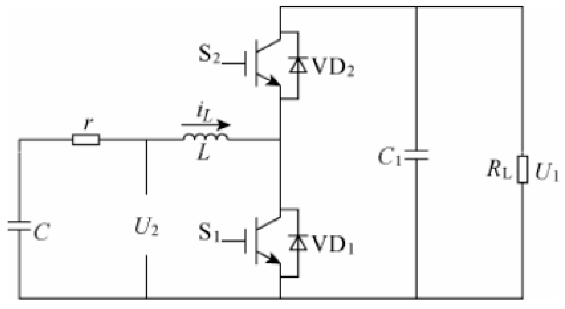
Figure 3.
The overall process of optimization.
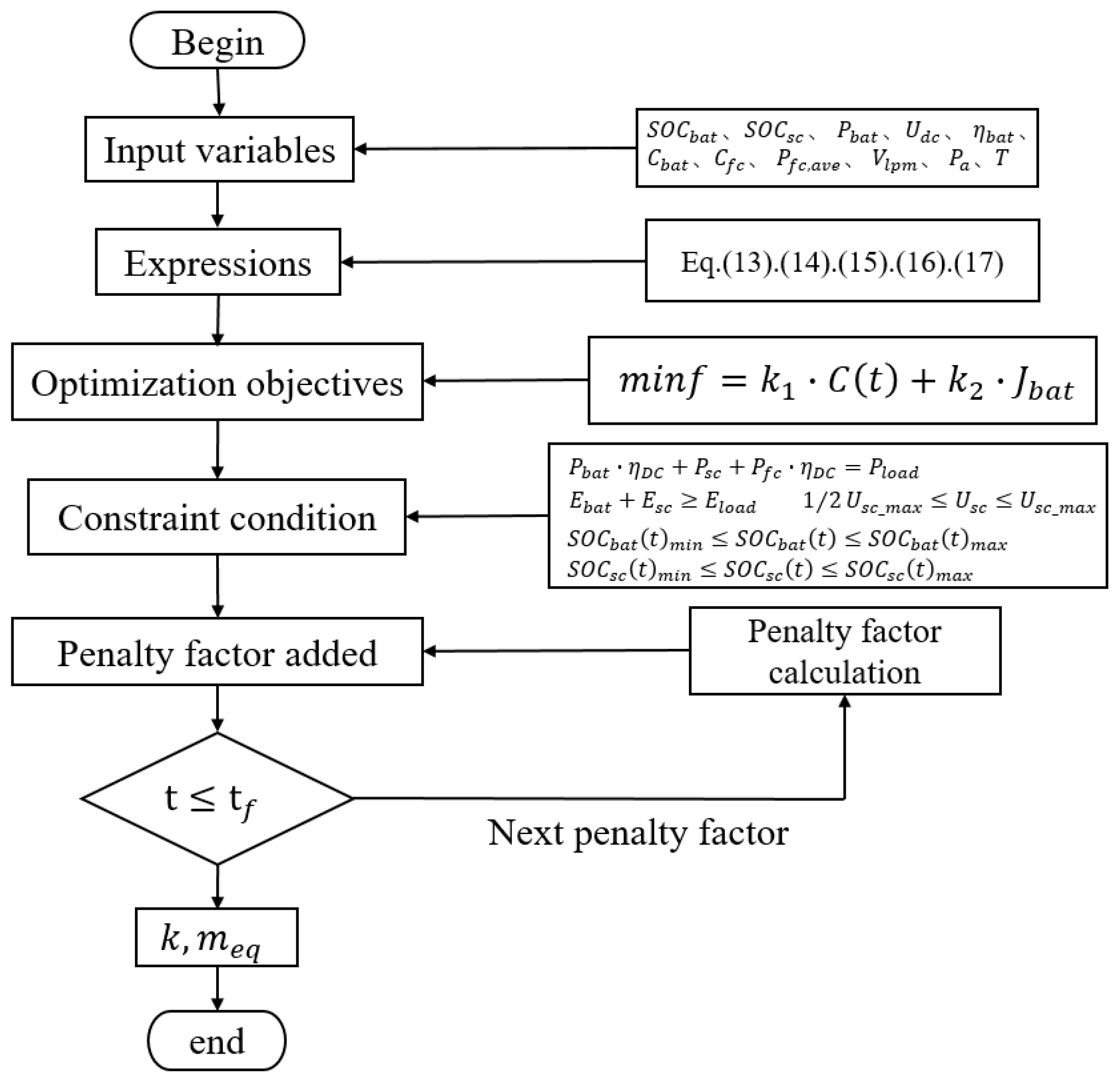
Figure 4.
Dual closed-loop PI control chart.
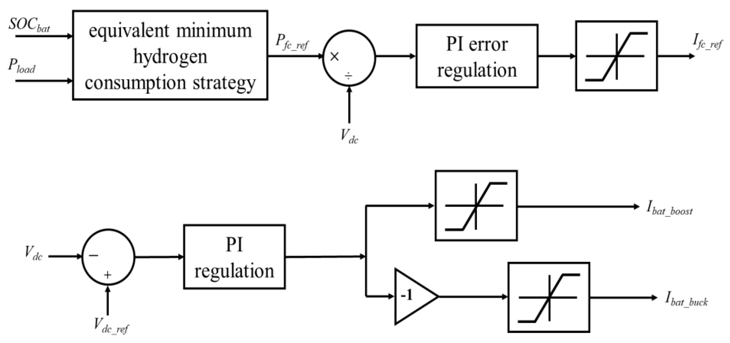
Figure 5.
S-shaped penalty function curve.
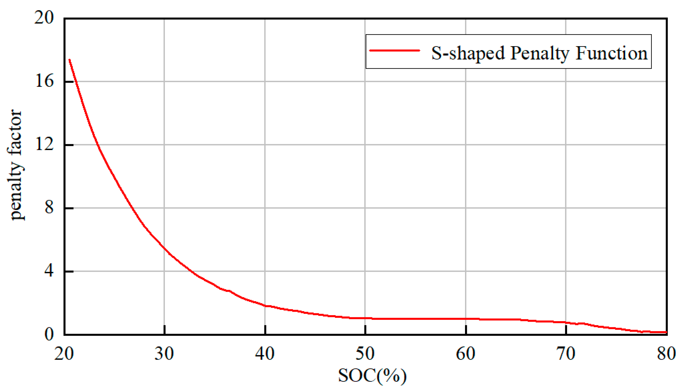
Figure 6.
S-shaped penalty function curve.
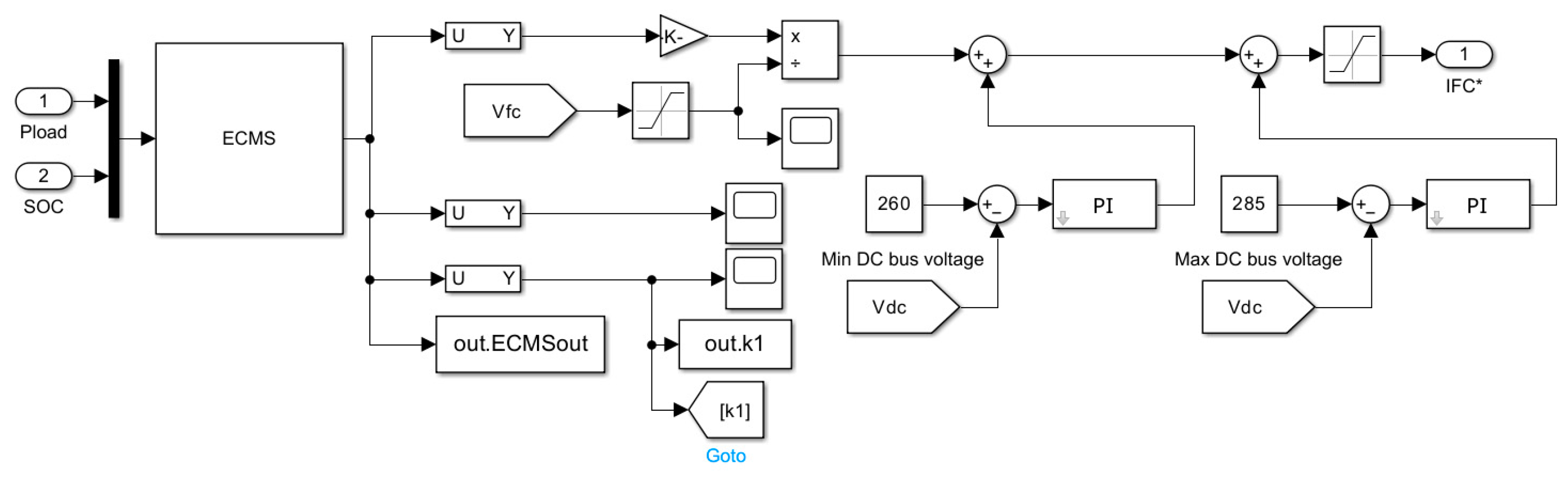
Figure 7.
Battery SOC affiliation function.
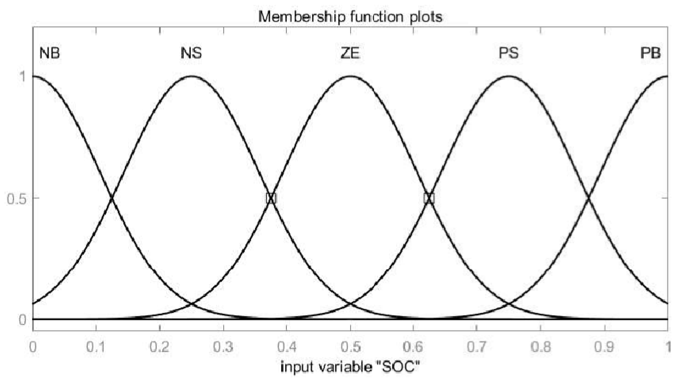
Figure 8.
Load affiliation function.
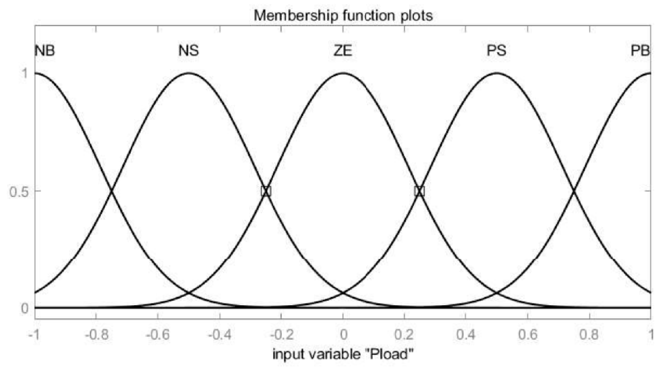
Figure 9.
Penalty factor affiliation function.
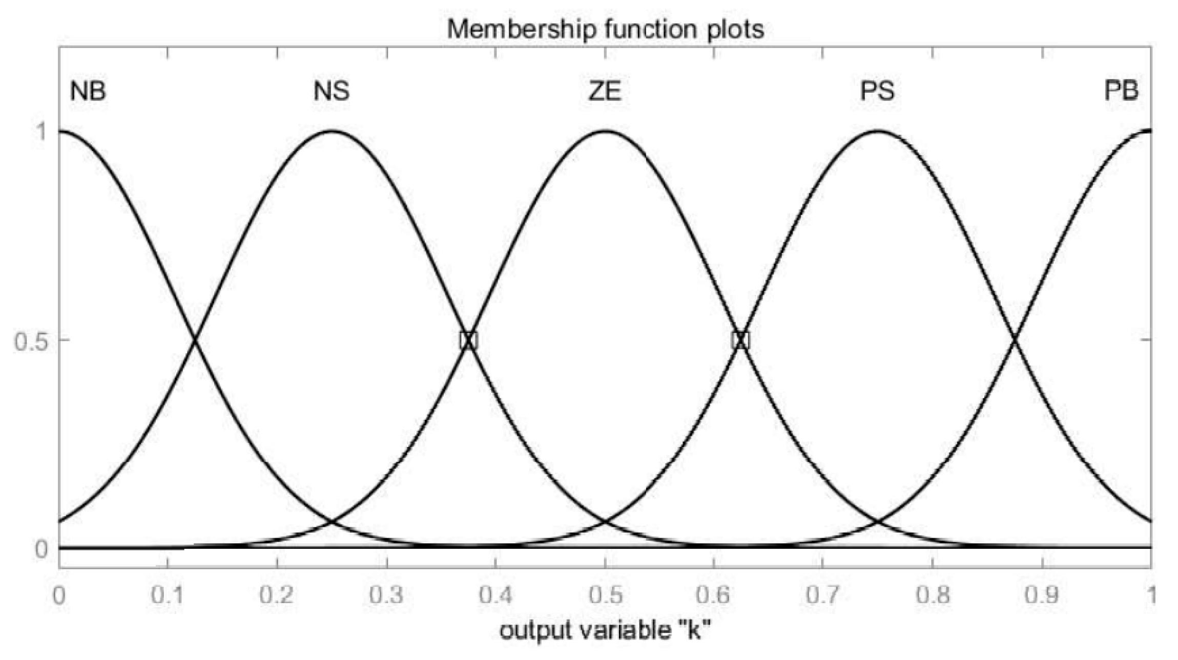
Figure 10.
Fuzzy 3D surface map
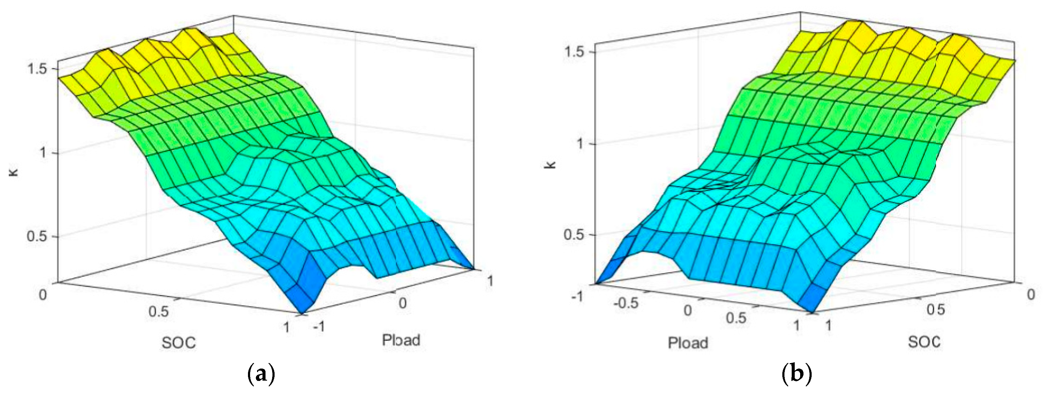
Figure 11.
Fuzzy logic control penalty factor control model.
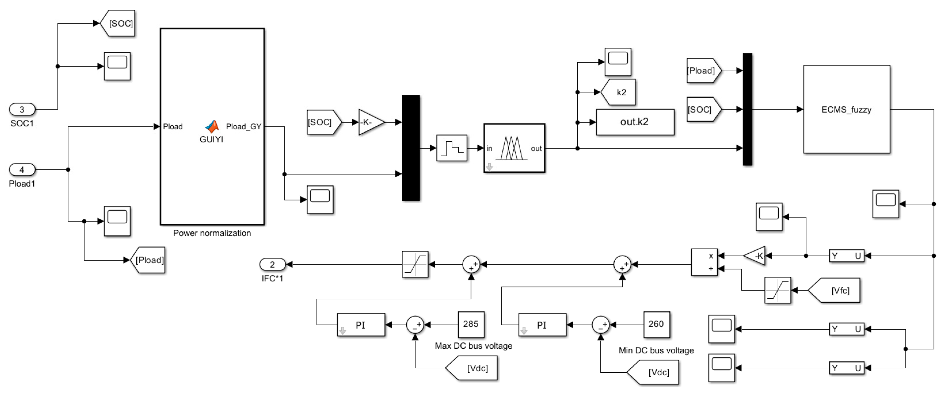
Figure 12.
Simplified typical operating loads.
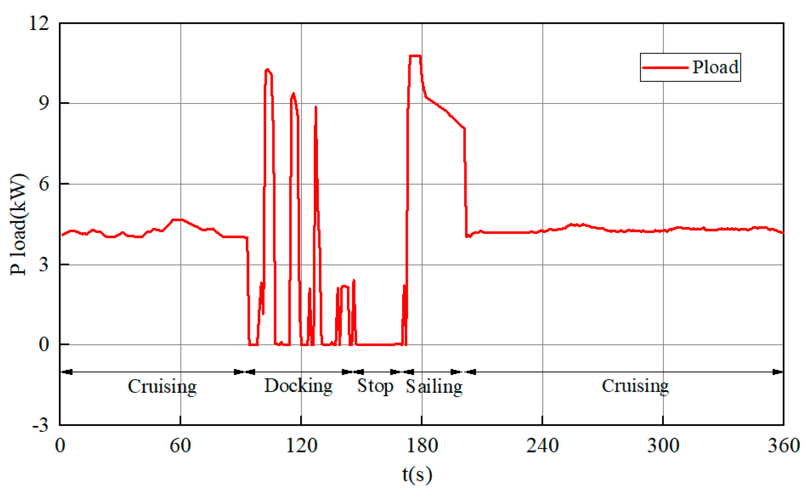
Figure 13.
Comparison of Lithium Battery Output Power.
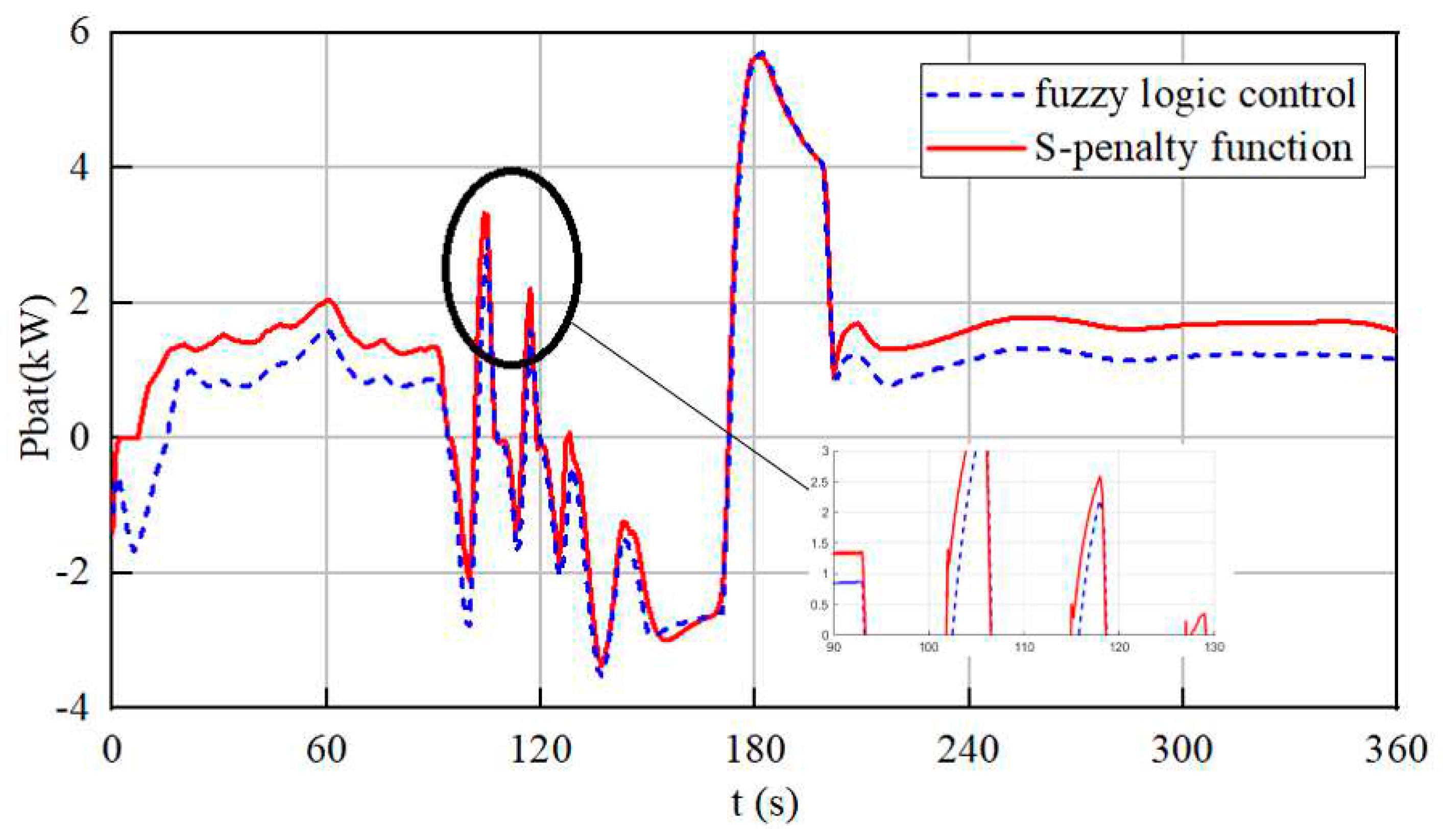
Figure 14.
Comparison of Lithium Battery SOC.
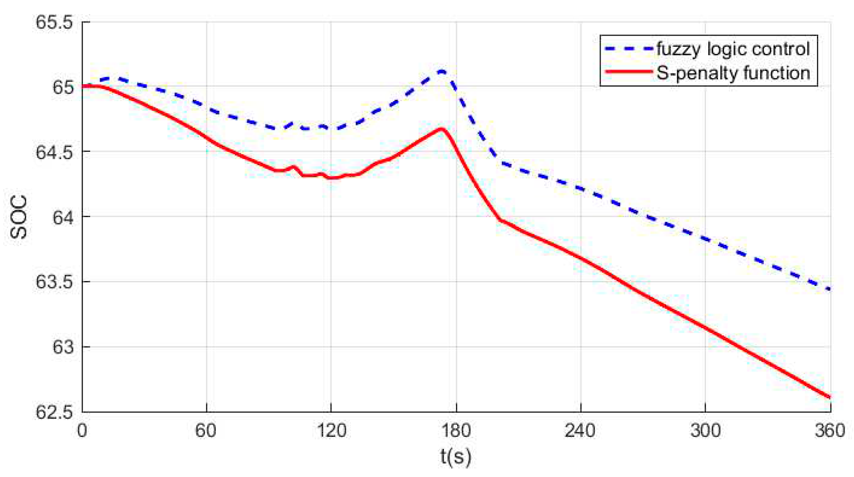
Figure 15.
Comparison of DC bus voltage.
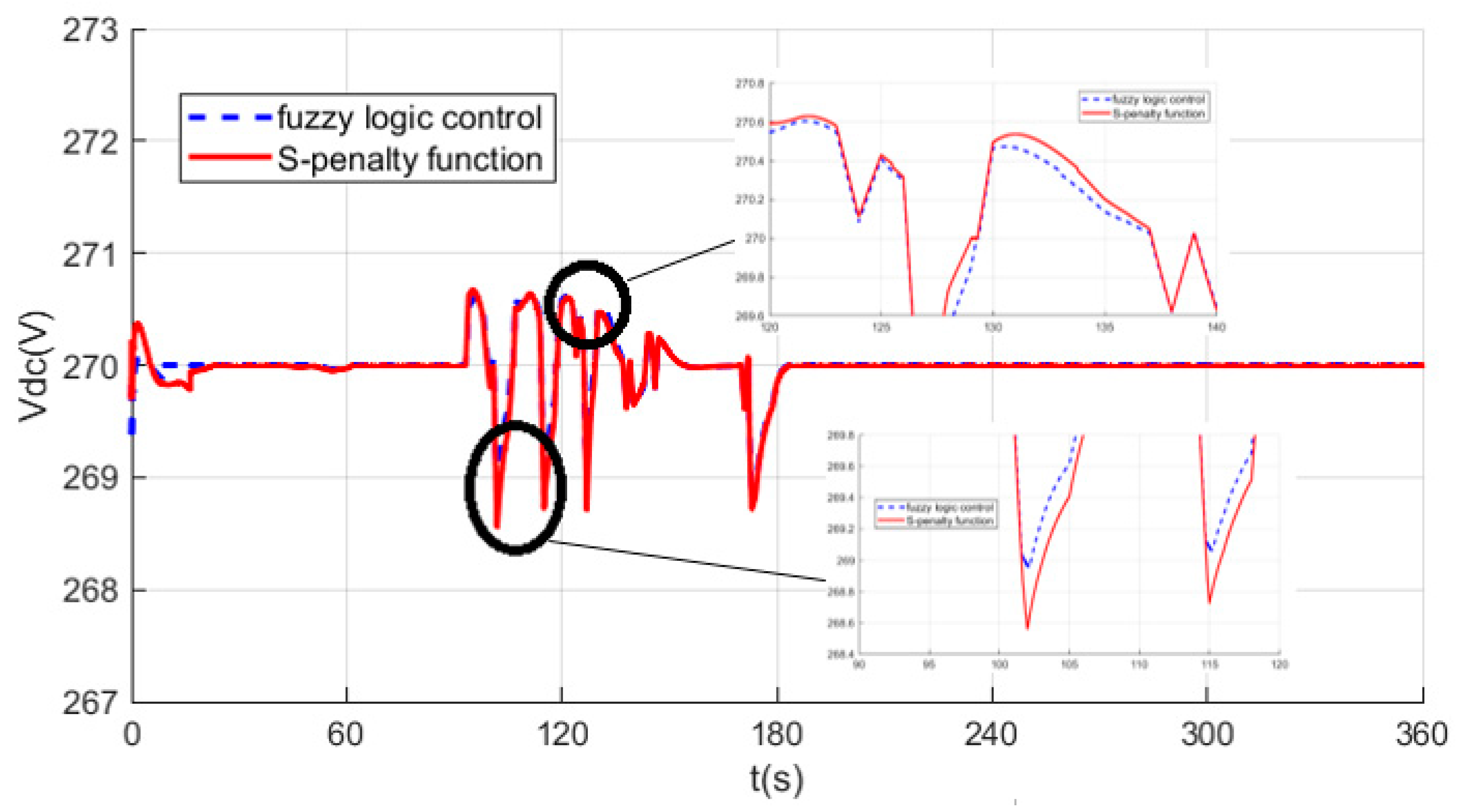
Figure 16.
Comparison of Equivalent hydrogen consumption.
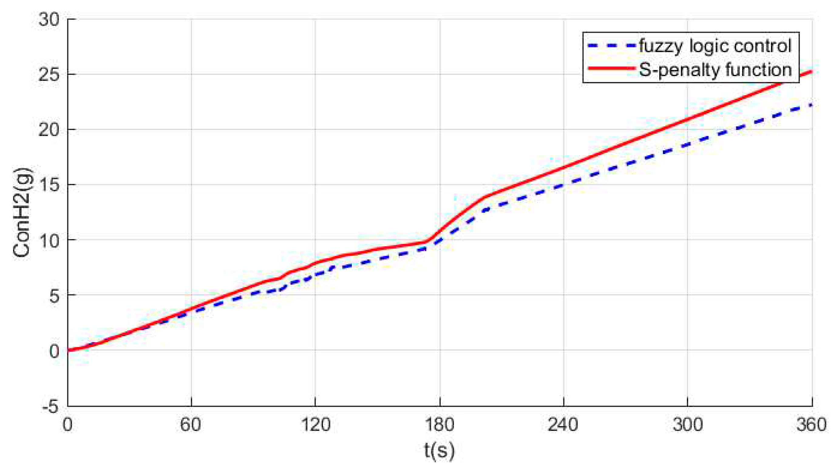
Table 2.
Initial parameter settings for simulation experiments.
| parameters | value |
|---|---|
| Lithium battery initial SOC | 65% |
| Supercapacitor Initial SOC Busbar voltage reference value Total simulation time Simulation step Lithium battery type Supercapacitor type |
75% 560V 360s 0.0001s IFR 32650-5000 BMOD0165-P048-C01 |
Disclaimer/Publisher’s Note: The statements, opinions and data contained in all publications are solely those of the individual author(s) and contributor(s) and not of MDPI and/or the editor(s). MDPI and/or the editor(s) disclaim responsibility for any injury to people or property resulting from any ideas, methods, instructions or products referred to in the content. |
© 2023 by the authors. Licensee MDPI, Basel, Switzerland. This article is an open access article distributed under the terms and conditions of the Creative Commons Attribution (CC BY) license (http://creativecommons.org/licenses/by/4.0/).
Copyright: This open access article is published under a Creative Commons CC BY 4.0 license, which permit the free download, distribution, and reuse, provided that the author and preprint are cited in any reuse.


