
Submitted:
27 August 2025
Posted:
28 August 2025
You are already at the latest version
Abstract
To address the challenges of high fuel consumption and emissions in a traditional diesel-powered inland law enforcement vessel, a retrofit design incorporating a methanol-electric hybrid propulsion system was proposed. Corresponding energy management strategies were developed using both rule-based (RL) and dynamic programming (DP) algorithms. To further enhance the energy management performance, a collaborative optimization algorithm integrating DP with an adaptive neural fuzzy inference system (ANFIS) is introduced. This hybrid approach leverages the global optimization capability of DP and the real-time adaptive learning characteristics of ANFIS to achieve efficient power distribution, thereby improving fuel economy and reducing emissions. A simulation model of the ship’s methanol-electric hybrid propulsion system was first developed based on methanol engine bench test data and integrated with models of other powertrain components. The DP algorithm was employed to solve for the optimal control sequence offline. Subsequently, ANFIS was used to learn the DP-derived optimization results online, generating real-time energy allocation rules adapted to actual operating conditions. This method significantly reduces computational burden and enhances system responsiveness. Simulation results demonstrate that, compared to the RL algorithm, the proposed DP-ANFIS algorithm reduces total energy consumption by 78.53% while increasing the battery state of charge (SOC) by 3.24%. In terms of fuel economy, methanol consumption is reduced by 64.95%, and the brake-specific fuel consumption (BSFC) is reduced by 81.26%. Regarding pollutant emissions, CO, HC, and NOx are reduced by 82.91%, 83.4%, and 15.2%, respectively. CO₂ emissions, a key indicator of carbon footprint, are reduced by 81.12%. These performance improvements are comparable to those achieved by a DP-only energy management strategy. Finally, hardware-in-the-loop tests further confirm the practical feasibility of the DP-ANFIS algorithm for real-world engineering applications. This method offers a novel technical pathway for intelligent energy management in marine hybrid propulsion systems, combining significant theoretical value with strong potential for engineering implementation.
Keywords:
hybrid propulsion system
; methanol engine
; dynamic programming
; adaptive neural fuzzy inference system
; hardware-in-the-loop
1. Introduction
Under the dual pressures of energy conservation, emissions reduction, and carbon neutrality targets within the global shipping industry [1,2], hybrid-powered vessels have emerged as a pivotal direction for green transformation due to their high efficiency and low emissions [3]. As an integral component of the shipping sector, inland waterway vessels face particularly acute emission challenges, underscoring the urgent need to develop new propulsion systems that harmonize economic viability with environmental sustainability [4,5]. Methanol fuel, recognized for its carbon-neutral potential, safety in storage and transportation, and technological maturity, is considered a promising alternative to conventional fossil fuels [6]. Meanwhile, electric propulsion systems, leveraging the synergy between energy storage systems and electric motors, can substantially enhance energy efficiency and reduce pollutant emissions [7]. Nevertheless, the dynamic coupling characteristics between methanol engines and electric systems, combined with the complex and variable operational profiles of vessels—such as cruising, acceleration, and berthing—pose considerable challenges in designing energy management strategies, particularly in achieving overall control effectiveness and real-time responsiveness. Hence, the development of a methanol-electric hybrid power energy management approach specifically tailored to the operational characteristics of inland waterway vessels carries significant theoretical and practical importance.
Existing research on hybrid power systems for ships has predominantly concentrated on diesel-electric hybrids [8], composite power architectures [9], and fuel cell-based systems [10]. In contrast, methanol-electric hybrid propulsion systems have received comparatively limited attention, with insufficient investigation into the dynamic modeling of methanol engines and the coordinated control strategies for integrated electric propulsion. Furthermore, the highly variable operating conditions and stringent emission regulations specific to inland waterway navigation complicate the design of effective energy management strategies (EMS), underscoring the need for approaches that harmonize global optimization with real-time control performance.Current EMS methodologies for marine hybrid power systems can be broadly classified into three categories: rule-based, optimization-based, and intelligent algorithm-based strategies [11]. Rule-based methods—such as those employing state machines or fuzzy logic—are widely adopted owing to their simplicity and computational efficiency, yet they often depend heavily on expert knowledge and may underperform in multi-objective optimization scenarios [12]. Optimization-based techniques, including dynamic programming (DP) and equivalent consumption minimization strategies (ECMS), can achieve global optimality and exhibit high theoretical accuracy, but they typically require a priori knowledge of the driving cycle, are limited to offline applications, and suffer from high computational cost and poor real-time capability [13]. Meanwhile, intelligent algorithm-based EMS—though promising—still face challenges such as substantial data dependency, limited robustness in real-time operation, and safety concerns, indicating that further development and validation are necessary before they can be reliably deployed [14].
To address the aforementioned challenges, this study designs a methanol-electric hybrid propulsion system comprising a methanol engine and a lithium-ion battery pack, and proposes an energy management strategy (EMS) that integrates dynamic programming (DP) with an adaptive neuro-fuzzy inference system (ANFIS) to form a globally optimized real-time control framework. Specifically, a high-fidelity simulation model of the hybrid propulsion system is developed, incorporating methanol engine characteristics derived from bench test data along with models of other powertrain components. An EMS based on the DP-ANFIS algorithm is then designed to enhance both global optimization capability and real-time performance. This model accurately simulates the system’s energy efficiency and emission characteristics under typical navigation conditions, enabling a comparative analysis of the energy management performance among rule-based (RL), DP, and DP-ANFIS algorithms. Furthermore, a distributed hardware-in-the-loop (HIL) test platform based on the NI PXIe system is established to experimentally validate the real-time control performance and robustness of the proposed DP-ANFIS strategy. Through a research methodology combining theoretical modeling, simulation analysis, and experimental verification, this study provides a low-emission and high-efficiency energy management solution for inland waterway vessels, while also offering new perspectives on multi-objective cooperative control in hybrid propulsion systems.
2. Materials and Methods
This study centers on the retrofitting of a specific inland river law enforcement vessel, transitioning its conventional diesel-based propulsion system to a methanol-electric hybrid configuration. The hybrid system integrates a methanol engine-generator set, a lithium iron phosphate battery pack, a permanent magnet synchronous motor, and associated power conversion modules. Key components include a 250 kW rated methanol generator set, a 200 kW peak power permanent magnet synchronous motor, and a lithium-ion battery pack with a rated capacity of 200 Ah.A high-fidelity system simulation model was developed using the MATLAB/Simulink environment. Leveraging bench test data from the CHG234V8MPI methanol engine, a MAP-based model was constructed to characterize engine power, fuel consumption, and emission performance. This model was coupled with motor efficiency maps and a dynamic state-of-charge (SOC) battery model, enabling a comprehensive multi-physics co-simulation of the entire hybrid propulsion system.
To optimize the energy management of the hybrid system, this study designed three control strategies: a heuristic rule-based (RB) strategy, a global optimization strategy utilizing dynamic programming (DP), and a collaborative DP-ANFIS strategy that integrates DP with an adaptive neuro-fuzzy inference system (ANFIS).In the DP approach, the required power and battery state of charge (SOC) are employed as state variables, while the output power of the methanol engine serves as the decision variable. The optimal control sequence is computed over a 150-step horizon using a backward search algorithm.For the DP-ANFIS strategy, the optimized control sequences generated by DP are used to train a Sugeno-type fuzzy inference system within the ANFIS framework. A hybrid learning algorithm is then applied to optimize the membership functions and rule base, enabling effective real-time power allocation.
Simulation studies were conducted under typical inland waterway operating conditions to evaluate and compare the performance of the three control strategies in terms of fuel consumption, emission reduction, and battery state of charge (SOC) maintenance. Furthermore, a hardware-in-the-loop (HIL) test platform was established using an NI PXIe dual real-time system. Through a distributed architecture, real-time closed-loop validation of both the control strategies and the plant model was achieved, confirming the feasibility and robustness of the DP-ANFIS algorithm for practical engineering applications.
3. Methanol-Electric Hybrid Propulsion System for Marine Applications
3.1. System Configuration and Key Parameters
The subject of this study is an inland river law enforcement vessel (as shown in Figure 1). Originally equipped with a conventional diesel propulsion system, the vessel exhibited relatively high emissions under typical operating conditions, failing to comply with national emission control zone regulations. To support green navigation objectives, the vessel is retrofitted with a methanol-electric hybrid propulsion system, which integrates a methanol engine and a lithium-ion battery pack. The retrofit aims to maintain the original navigation performance—including speed and range—while introducing an intelligent energy management system. Furthermore, the energy management strategy is optimized for typical operating profiles to reduce fuel consumption and pollutant emissions. The key design parameters of the vessel are summarized in Table 1.
3.2. Design of a Marine Methanol-Electric Hybrid Propulsion System
As illustrated in Figure 2, the methanol-electric hybrid propulsion system developed in this study employs a modular architecture, comprising a power generation module, an energy storage module, a power conversion module, and a propulsion execution module. Through tailored energy management strategies, the system enables coordinated operation among these modules across various working conditions. This integrated approach enhances energy utilization efficiency and reduces pollutant emissions, while maintaining the required propulsion performance.
The power generation module employs a methanol-fueled generator set, which integrates a methanol engine and a generator, serving as the primary power source. The methanol engine and the generator are coupled via an electromagnetic clutch, allowing rapid disconnection of the mechanical linkage. This design enables the system to operate in pure electric propulsion mode by disengaging the methanol engine, thereby avoiding unnecessary mechanical wear caused by reverse drag.
The energy storage module consists of a lithium iron phosphate (LiFePO₄) battery pack connected to the DC bus via a bidirectional DC/DC converter. The Battery Management System (BMS) provides real-time monitoring of the State of Charge (SOC), enabling the energy management system to maintain the hybrid propulsion system within its optimal operating range.
The power conversion module comprises the following key components: an AC/DC rectifier that converts three-phase AC power from the generator set to DC power; a bidirectional DC/DC converter facilitating energy transfer between the battery pack and the DC bus; a DC/AC inverter that drives the propulsion motor by converting DC power to AC; and an additional AC/DC rectifier that converts regenerated AC power from the reversible motor during braking or reversing into DC power for feedback into the DC bus.
The propulsion execution module utilizes high-efficiency permanent magnet synchronous motors (PMSM) to drive the propeller. This motors exhibit a maximum efficiency of up to 96% and support four-quadrant operation, enabling effective regenerative braking energy recovery.
Energy flow paths are divided into mechanical connection paths and electrical connection paths, and include both unidirectional and bidirectional energy flow directions.
Based on typical navigation profiles, the parameters of the ship’s methanol-electric hybrid propulsion system have been systematically matched. The resulting key power component parameters are summarized in Table 2.
3.3. Operational Modes of the Marine Methanol-Electric Hybrid Propulsion System
Based on the analysis of daily operational profiles of inland river law enforcement vessels, the hybrid propulsion system designed in this study incorporates the following primary operating modes:
3.3.1. All-Electric Propulsion Mode
The energy flow in all-electric propulsion mode is illustrated in Figure 3. This mode is primarily employed during vessel startup, port maneuvering, and extended low-speed cruising. Its key technical characteristic is the complete shutdown of the methanol engine, enabling true zero-emission operation. Compared to conventional propulsion systems, this mode offers notable advantages including significantly reduced noise, faster dynamic torque response, and improved speed control accuracy.
3.3.2. Methanol Range-Extended Propulsion Mode
The energy flow in methanol range-extended propulsion mode is illustrated in Figure 4. This mode is primarily used during medium-speed cruising, battery charge-sustaining phases, extended voyages, and port standby charging. Its key technical characteristics include dual energy paths for both propulsion and charging, allowing the methanol engine to operate consistently within its highest efficiency range. Surplus power is utilized for efficient battery charging. This power management approach significantly reduces fuel consumption and pollutant emissions.
3.3.3. Hybrid Propulsion Mode
The energy flow in hybrid propulsion mode is depicted in Figure 5. This mode is primarily employed during high-speed navigation, emergency collision avoidance, heavy-load operations, and similar high-power demand scenarios. Its key technical feature is a redundant dual-power-source configuration, which enhances system reliability. By leveraging the peak-shaving and valley-filling capability of the battery pack, the system achieves coordinated power distribution between the methanol engine and the energy storage unit, while significantly improving dynamic response performance.
3.3.4. Regenerative Braking Mode
The energy flow during regenerative braking mode is illustrated in Figure 6. This mode is primarily activated during vessel deceleration, berthing maneuvers, and emergency stops. Its key technical advantages include efficient energy recovery, extended battery service life, and reduced mechanical braking losses, thereby maximizing energy utilization and minimizing emissions.
Based on the operational characteristics of the four aforementioned working modes of the marine methanol-electric hybrid propulsion system, along with the functional features and parameter thresholds of its key power components, a mode switching logic was designed as illustrated in Figure 7.
4. Modeling of the Marine Methanol-Electric Hybrid Propulsion System
This study developed a high-fidelity simulation model of the marine hybrid propulsion system using the MATLAB/Simulink platform, incorporating experimental data from bench tests of the CHG234V8MPI methanol engine. The modeling effort emphasized detailed characterization of key power components, structured as follows: first, a quasi-steady-state model of the methanol engine was established based on empirical test data; second, a permanent magnet synchronous motor model was developed to balance efficiency and dynamic performance; concurrently, a lithium-ion battery pack model accounting for dynamic state-of-charge (SOC) variations was constructed, and an energy management strategy for power distribution was designed. Throughout the modeling process, special emphasis was placed on capturing the dynamic coupling effects between subsystems. Real-time data interaction interfaces were incorporated to ensure the accuracy of dynamic responses in the overall hybrid propulsion system simulation.
4.1. Methanol Engine Modeling
This study centers on the CHG234V8MPI methanol engine, for which operational characteristics were obtained through bench testing. A lookup-table-based simulation model of the engine was developed using the experimental data. The engine operates on spark ignition and features an intake manifold injection system, configured as a V-type 8-cylinder high-speed methanol-fueled unit. It represents an upgraded version of the CHG234V8MPI series marine gas engine. The main performance parameters and technical specifications of the test prototype are summarized in Table 3. During testing, key parameters—including fuel consumption rate, emission characteristics, and power output across various operating conditions—were recorded, providing essential data for constructing an accurate engine simulation model.
As illustrated in Figure 8, Figure 9, Figure 10, Figure 11, Figure 12, Figure 13, Figure 14 and Figure 15, comprehensive bench testing was conducted to characterize the multi-dimensional performance of the CHG234V8MPI methanol engine. Figure 8 presents the overall test setup, while the subsequent Figures detail specific performance metrics: engine power distribution (Figure 9), methanol consumption rate (Figure 10), brake-specific fuel consumption (BSFC, Figure 11), carbon monoxide (CO) emissions (Figure 12), carbon dioxide (CO₂) emissions (Figure 13), unburned hydrocarbon (HC) emissions (Figure 14), and nitrogen oxides (NOx) emissions (Figure 15). These performance characteristics are visualized as three-dimensional MAP diagrams, effectively capturing the engine’s behavior under varying speed and torque conditions. The data provide a critical foundation for subsequent system simulation and optimization efforts.
4.2. Permanent Magnet Synchronous Motor Modeling
4.2.1. Analysis of Dynamic Torque Characteristics
The dynamic torque response of the reversible motor is modeled using a first-order inertial element, represented by the following transfer function:
where denotes the actual output torque (), represents the torque command value (), and is the electromechanical time constant, typically set to 0.01 s. This transfer function captures the lag inherent in the motor’s torque response, with characterizing the electromagnetic inertia of the motor system.
4.2.2. Efficiency Modeling
An efficiency MAP model is established using two-dimensional interpolation:
where denotes the overall efficiency (%), represents the rotational speed (r/min), and is the load torque (). The full operating-condition efficiency data are obtained through bench testing, and a lookup table is constructed to enable rapid data retrieval during simulation.
4.2.3. Electro-Mechanical Energy Conversion
A bidirectional energy flow model is employed to calculate the power transfer:
where denotes the mechanical power at the shaft, and represents the electrical power on the DC bus. This model accurately describes the motor’s power conversion behavior during both propulsion and regenerative braking, forming a computational basis for energy management in hybrid power systems.
4.3. Lithium-Ion Battery Model
A standard lithium-ion battery model from Simulink is adopted in this study, with parameters configured to meet the power requirements of the marine methanol-electric hybrid propulsion system. The operational behavior of the battery is characterized as follows:
Charge/Discharge Characteristics: The battery terminal voltage is modeled using a piecewise function.
Under discharge condition ():
Under charging condition ():
where is the operating current (A), denotes the open-circuit voltage (V), K represents the polarization resistance (Ω), Q is the nominal capacity (Ah), indicates the extracted capacity (Ah), and A and B are empirical coefficients. The inclusion of the 0.1Q compensation term in the charging condition accurately captures the polarization effects during the charging process.
The state of charge (SOC) is dynamically updated in real time using the current integration method:
where is the initial charge capacity (Ah), denotes the instantaneous current (A)—defined as positive during discharge and negative during charging—and Q represents the nominal capacity (Ah).
The above lithium-ion battery model dynamically tracks the accumulated energy, providing an accurate representation of the actual energy state of the battery.
4.4. Integrated Modeling of the Marine Methanol-Electric Hybrid Propulsion System
By integrating simulation models of core power components—including the methanol engine, permanent magnet synchronous motor, and lithium-ion battery pack—along with key subsystems such as the energy management system and transmission system, a comprehensive co-simulation platform for the marine methanol-electric hybrid propulsion system has been developed. The overall architecture of the platform is illustrated in Figure 16. The integrated model explicitly captures the energy coupling relationship between the methanol engine and the lithium-ion battery pack. It enables detailed simulation and analysis of the dynamic performance of the hybrid propulsion system across various operational profiles.
4.5. Validation of the Marine Methanol-Electric Hybrid Propulsion System Model
To evaluate the accuracy of the developed simulation model, the output speed curve of the model was compared against a predefined target speed profile, as shown in Figure 17. The simulation results indicate that, over the 0–3000 second simulation period, the overall trend of the simulated speed curve aligns well with the predefined reference. However, the following characteristic discrepancies were observed:
- 1.
- Dynamic Response Characteristics
During acceleration and deceleration phases, the speed profile generated by the simulation model exhibits smoother transitions compared to the predefined reference, with a tracking lag of approximately 0.5 m/s. This discrepancy is primarily attributed to the dynamic delay of the internal combustion engine and the inherent inertia of the propulsion system.
- 2.
- Speed Tracking Performance Under Various Operating Conditions
The model demonstrates satisfactory speed tracking in low-speed steady-state and cruising segments. However, during the deceleration phase between 2700 and 3000 seconds, the hybrid propulsion system fails to provide immediate deceleration support, resulting in reliance on fluid resistance for speed reduction. This leads to a noticeable deviation from the predefined speed trajectory in this segment.
- 3.
- Mechanism of System Response Discrepancies
The electric drive system—comprising the motor and battery pack—ensures high tracking accuracy in low-speed operations due to its rapid response capability. In contrast, the dynamic delay of the methanol generator set restricts tracking performance during transient conditions. Nevertheless, the overall speed trend remains consistent, and the observed errors are within acceptable limits, thus not compromising subsequent simulation-based analysis and verification of the methanol-electric hybrid propulsion system.
Figure 17.
Speed tracking performance of the marine methanol-electric hybrid propulsion system.
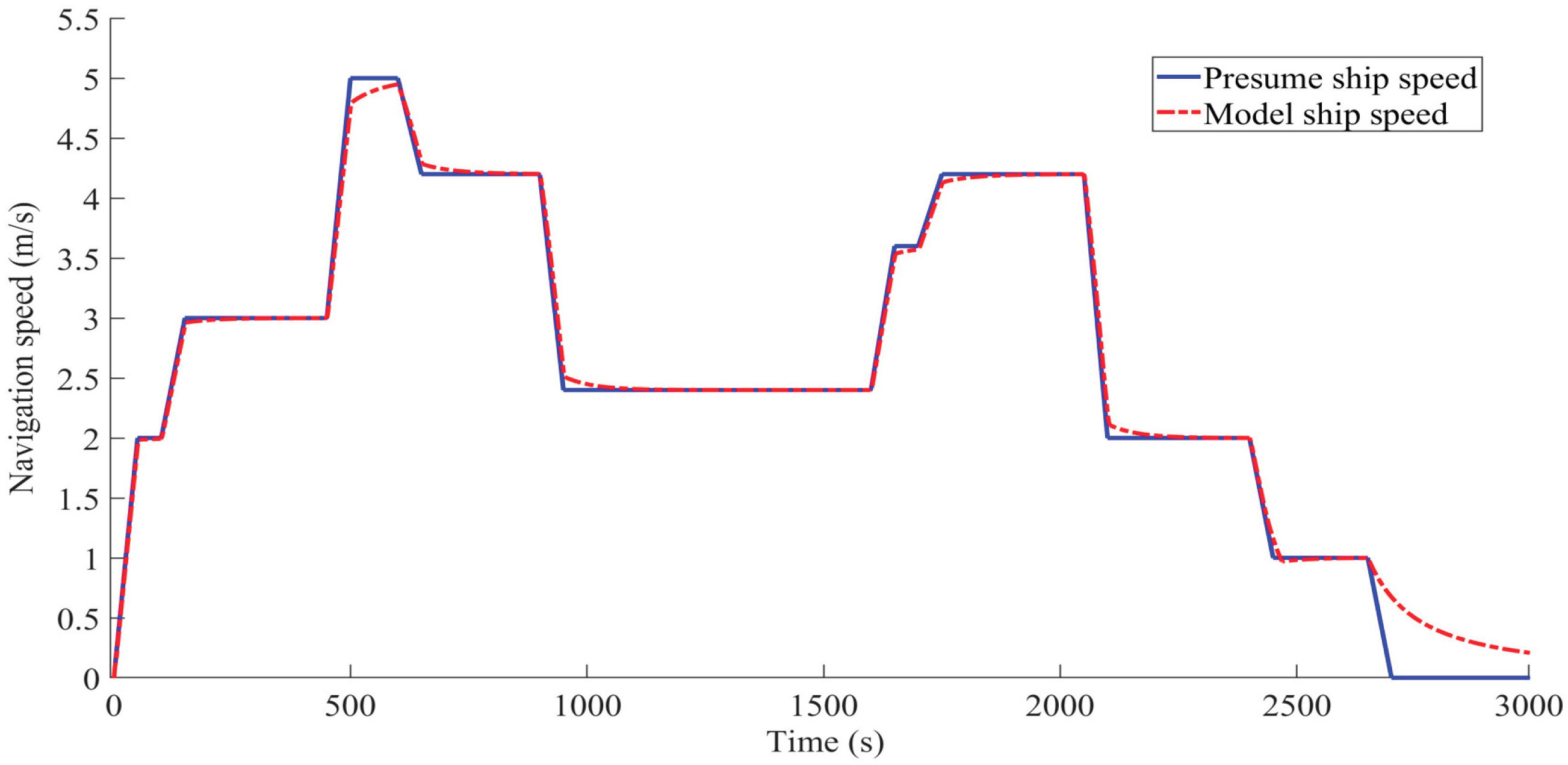
Through the above speed tracking validation, it is confirmed that the proposed simulation model meets the requirements for further performance evaluation and control strategy verification.
5. Rule-Based Energy Management Strategy
Based on the operational mode switching logic of the marine methanol-electric hybrid propulsion system illustrated in Figure 7, a rule-based energy management strategy is developed, as shown in Figure 18. This strategy comprehensively considers key parameters—including acceleration commands, battery state of charge (SOC), propulsion power demand, and battery output capability—to dynamically select the optimal operational mode and rationally allocate power among the energy sources.
In the rule-based energy management strategy developed in this study, the acceleration command is defined within the range of [-1, 1], where values in (0, 1] indicate acceleration and values in [-1, 0) represent deceleration. The state of charge (SOC) reflects the remaining capacity of the battery, while denotes the power demand of the ship’s propulsion system. Additionally, describes the maximum discharge power of the battery pack. These parameters collectively govern the operational state of the marine methanol-electric hybrid propulsion system.
6. Dynamic Programming-Based Energy Management Strategy
Dynamic programming (DP) is a multi-stage decision optimization method founded on Bellman’s principle, widely applied to problems such as shortest-path search and energy management in hybrid power systems [15]. The DP algorithm decomposes the problem into multiple stages, each characterized by discrete states and feasible decisions. By evaluating the transition cost between states, it determines the globally optimal control sequence [16]. In the context of hybrid propulsion system energy management, the DP approach utilizes time as the stage variable and incorporates key parameters such as the battery state of charge (SOC) and propulsion power demand. It optimizes the power split between the methanol generator set and the battery pack to minimize fuel consumption while maintaining system constraints [17].
The advantage of the dynamic programming (DP) algorithm in energy management for hybrid propulsion systems lies in its predictive capability [18]. By comparing the preset ship speed with the simulated speed and incorporating a ship dynamics model, the DP algorithm pre-calculates the required propulsion power, thereby generating a predictive demand power input. As illustrated in Figure 19, the DP-based energy management controller uses the demanded propulsion power and the battery state of charge (SOC) as inputs. Through optimization, it determines and transmits the output power of the methanol generator set, the propulsion motor speed, and the battery pack output power to the hybrid propulsion system model. This predictive power allocation mechanism allows the energy management strategy to achieve near-optimal control performance.
Based on the principles of dynamic programming (DP) and the operational characteristics of the marine methanol-electric hybrid propulsion system, a DP-based energy management algorithm was designed in this study. The specific design procedure is outlined as follows:
- 1.
- State Variables
In the marine methanol-electric hybrid propulsion system, the state of charge (SOC) of the battery pack is selected as the state variable, as it effectively reflects the overall operational characteristics of the hybrid system while satisfying the requirements of non-aftereffect and observability. The SOC variation range is constrained between 30% and 60% with a discretization step of 0.1% to prevent overcharging or over-discharging. The dynamic behavior of the SOC can be described by Equation (7):
In the equation, represents the state variable of the k-th stage.
- 2.
- Decision Variable
In the marine methanol-electric hybrid propulsion system, the output power of the methanol engine-generator set is chosen as the decision variable, as expressed in Equation (8):
where represents the decision variable at the k-th stage. This selection is motivated by the objective of operating the methanol engine at its minimum fuel consumption point, thereby ensuring optimal fuel economy.
- 3.
- Stage Division
Although dynamic programming can yield globally optimal solutions, it is necessary to avoid the curse of dimensionality that arises from an excessive number of stages. To balance computational accuracy and complexity, the navigation profile in this study is divided chronologically into 150 stages, each with a duration of 20 seconds. The stage variable thus takes values in the set = 1, 2, …, 150.
- 4.
- State Transition Equation
The state transition equation defines how the current state and the decision variable collectively determine the subsequent state . It is mathematically expressed as:
Given the complex relationship between the methanol engine power and the battery state of charge (SOC), this study utilizes the MATLAB System Identification Toolbox to develop a nonlinear model that captures the dynamic characteristics of the system. A state-space model was identified and validated against experimental data, achieving a fitting accuracy of 95.75% with a 96% confidence interval. The errors were maintained within 5%, confirming that the state-space model accurately represents the system dynamics. The functional expression of the state-space model is given by Equation (10).
In the state-space model described above, denotes the current time (in seconds), and represents the sampling interval (in seconds). Mathematically, is defined as the differential form of the state variable , which characterizes the real-time state of the system at time . The input is expressed in matrix form, specifically comprising the output power of the methanol generator set and the motor output power , i.e., . The model parameters include the initial state and the four coefficient matrices A, B, C, and D, which are identified through systematic parameter estimation. These coefficients comprehensively capture the dynamic relationships among the variables in the state-space representation.
- 5.
- Cost Function
The cost function serves to evaluate the quality of decisions made by the energy management strategy. In this study, with the objective of optimizing fuel economy, the cost function is defined as follows in Equation (11):
where denotes the brake-specific fuel consumption rate, measured in .
The optimal cost function is designed to minimize the total fuel consumption, as expressed in Equation (12):
- 6.
- Constraints
To ensure safe and stable operation of the system, the following constraints are imposed (Equations 13–15):
Battery SOC limits:
Battery power range constraints:
Methanol engine power limits:
In summary, the DP algorithm achieves optimal fuel economy for the marine methanol-electric hybrid propulsion system through stage-wise decomposition, state transition optimization, and constraint enforcement.
This study employs a backward-solving approach to address the dynamic programming problem. The detailed computational procedure is illustrated in Figure 20.
7. Energy Management Strategy Based on DP-ANFIS Algorithm.
The optimal control sequence derived from the dynamic programming (DP) algorithm for energy management of the marine methanol-electric hybrid propulsion system is utilized as training data for the Adaptive Neuro-Fuzzy Inference System (ANFIS). An adaptive modeling approach is employed to construct the fuzzy inference system. The hybrid learning algorithm—particularly suitable for controlling complex systems with nonlinear and time-varying dynamics—is applied to optimize both the fuzzy rules and the parameters of the membership functions [19].
The operational procedure of the DP-ANFIS algorithm is as follows: From the optimal control sequence generated by the DP algorithm, the required power of the marine methanol-electric hybrid propulsion system and the battery SOC are chosen as input variables, while the output power of the methanol engine is set as the output target. To enhance training accuracy, the min–max normalization method is applied to scale the data to the interval [0, 1]. Subsequently, the ANFIS toolbox (anfisedit) within the MATLAB environment is employed to construct a Sugeno-type fuzzy inference system with two inputs and one output. Key parameter configurations include: the AND operator is set to algebraic product (prod), the OR operator to probabilistic OR (probor), and the defuzzification method to weighted average (wtaver). After configuration, the normalized data is imported into the toolbox for model training [20,21].
In this study, the subtractive clustering method is employed to construct the fuzzy inference system (FIS), with all parameters maintained at their default settings [22]. The resulting ANFIS control system architecture is illustrated in Figure 21.
As illustrated in Figure 21, the adaptive neuro-fuzzy inference system (ANFIS) developed in this study employs a five-layer feedforward network architecture, with each layer serving a distinct function: the first layer is the input layer, consisting of two independent input variables; the second layer performs fuzzification, mapping each input variable through five Gaussian membership functions; the third layer handles rule generation, automatically producing five fuzzy rules; the fourth layer implements the inference mechanism, converting these rules into five sets of linear output functions; and the fifth layer executes defuzzification to produce the final output. During initialization, all input variables are normalized to the interval [0, 1], and the parameters of the membership functions are adaptively optimized using training data. Notably, the output functions adopt a linear formulation, effectively complementing the nonlinear fuzzification applied to the input variables.
As described earlier, a hybrid algorithm integrating backpropagation (BP) and the least squares method is employed to train the ANFIS system. The number of training epochs is set to 35, with the error threshold specified as zero. As shown in the training results in Figure 22, the system error stabilizes when the number of iterations approaches 30, eventually converging to a final value of 0.0030689. This outcome confirms the rationality of the chosen training configuration.
As shown in Figure 23 and Figure 24, computational analysis of the training data reveals that the ANFIS system exhibits strong adaptive capabilities: it automatically generated five mutually consistent fuzzy inference rules. The membership function distributions for each input variable display non-uniform characteristics, and the flexibility in the shape of the fuzzy membership subsets surpasses that of fixed rule-based fuzzy control systems. This indicates the system’s ability to autonomously adjust parameter boundaries according to optimal output values derived from the training data. Furthermore, as illustrated in Figure 25, the output power surface of the methanol engine after training is smooth and well-regulated, demonstrating that the engine consistently operates within its optimal range. This contributes significantly to reducing both fuel consumption and pollutant emissions.
8. Simulation Results and Analysis
To evaluate the performance of the DP-ANFIS-based energy management strategy for the marine methanol-electric hybrid propulsion system, this study integrated three control strategies—rule-based, DP-based, and DP-ANFIS-based energy management controllers—into the simulation model illustrated in Figure 16. Simulations were conducted under typical navigation conditions, as depicted in Figure 17. The following performance metrics were collected and analyzed: methanol consumption, brake-specific fuel consumption (BSFC), battery state of charge (SOC), and emissions of CO, CO₂, HC, and NOx.
To facilitate a clearer comparison of algorithmic performance, the output results of the marine methanol-electric hybrid propulsion system under the three energy management strategies are categorized and presented in Figure 26, Figure 27, Figure 28, Figure 29, Figure 30, Figure 31 and Figure 32.
Qualitative analysis of the results presented in Figure 26, Figure 27, Figure 28, Figure 29, Figure 30, Figure 31 and Figure 32 indicates that, throughout the entire voyage, the DP-based energy management strategy—by leveraging the peak-shaving and valley-filling capabilities of the electric drive system—effectively maintained the methanol engine within its optimal operating range and substantially reduced its operational duration. Compared to the rule-based (RL) strategy, the DP approach demonstrated significant advantages in terms of fuel economy, pollutant emissions reduction, and battery state of charge (SOC) stabilization, highlighting its superior global optimization performance.
Furthermore, the DP-ANFIS-based energy management strategy developed in this study incorporates pre-learned optimization results from the DP strategy. As a result, all its output metrics follow trends consistent with the DP-based approach and are markedly superior to those achieved by the RL strategy. Although the performance of the DP-ANFIS strategy does not entirely match that of the pure DP algorithm due to neural network learning errors, it still delivers significantly improved optimization compared to the rule-based method. More importantly, unlike the DP algorithm—which is confined to offline optimization—the DP-ANFIS strategy supports real-time online optimization. Thus, the proposed DP-ANFIS approach combines strong global optimization performance with real-time capability, offering considerable promise for practical engineering applications.
From a quantitative perspective, the performance indicators of the marine methanol-electric hybrid propulsion system under the three energy management strategies were visualized and quantified over the full navigation profile, as shown in Figure 33, Figure 34, Figure 35, Figure 36, Figure 37, Figure 38 and Figure 39. The comparison clearly demonstrates that both the DP and DP-ANFIS strategies achieve significantly lower fuel consumption and pollutant emissions compared to the rule-based (RL) strategy. Moreover, the DP-ANFIS strategy maintains a notably higher battery SOC than the RL approach, while its performance metrics closely approximate those of the DP algorithm.
These quantitative findings are consistent with the earlier qualitative analysis, further confirming that the DP-ANFIS-based strategy delivers substantially improved optimization over the RL method and performs nearly on par with the DP-based strategy. Additionally, the DP-ANFIS strategy excels in online real-time capability, representing a practical advantage over the purely offline DP algorithm.
The total energy consumption W of the marine methanol-electric hybrid propulsion system across all operational conditions is calculated using the energy superposition method, as expressed in Equation (16):
where denotes the energy equivalent of methanol consumption (in ), and represents the energy consumed by the battery pack (in ).
The methanol-related energy component is computed using the integral form given in Equation (17):
The key parameters are defined as follows:
: fuel mass flow rate ();
: calorific value of methanol, taken as 19.5×10³ .
The energy consumption of the battery pack is calculated using Equation (18):
The main variables involved include:
: propulsion system power demand (kW);
: auxiliary equipment power consumption (kW);
: output power of the methanol engine (kW);
: system energy conversion efficiency (set at 80%).
To quantitatively compare the results presented in Figure 33, Figure 34, Figure 35, Figure 36, Figure 37, Figure 38 and Figure 39 and the total energy consumption computed via Equations (16)–(18), Table 4 summarizes the performance improvements of the marine methanol-electric hybrid propulsion system under the DP and DP-ANFIS strategies relative to the rule-based (RL) energy management strategy.
As indicated by the comparative data in Table 4, under full navigation conditions, the DP algorithm—as a global optimization method—exhibits comprehensive advantages in both energy efficiency and emission control for the marine methanol-electric hybrid propulsion system. Compared to the rule-based (RL) strategy, the DP algorithm reduces the total energy consumption by 80.85% while increasing the battery state of charge (SOC) by 4.63%. In terms of fuel economy, methanol consumption is reduced by 81.33%, and brake-specific fuel consumption (BSFC) by 82.65%. Regarding pollutant emissions, the DP algorithm achieves reductions of 83.84% for CO, 85.92% for HC, and 23.07% for NOx. Carbon dioxide (CO₂) emissions, a key indicator of decarbonization, are reduced by 82.79%.
The DP-ANFIS algorithm, which surpasses the RL strategy in optimization effectiveness and outperforms the DP algorithm in real-time performance, reduces the total energy consumption by 78.53% compared to the RL approach, while increasing the battery SOC by 3.24%. Methanol consumption decreases by 64.95%, and BSFC by 81.26%. Emissions of CO, HC, and NOx are reduced by 82.91%, 83.4%, and 15.2%, respectively, while CO₂ emissions are cut by 81.12%.
As demonstrated in the preceding analysis and Table 4, the DP-ANFIS algorithm—trained on the globally optimal control sequences generated by the DP algorithm—delivers optimization performance closely matching that of the DP approach, approaching near-global optimality. Consequently, all performance metrics of the DP-ANFIS strategy significantly surpass those of the rule-based (RL) energy management strategy, with particularly pronounced reductions in CO₂ emissions, thereby strongly supporting carbon mitigation goals. Moreover, as a globally-oriented online energy management strategy, the DP-ANFIS algorithm offers substantial advantages in real-time operational performance.
9. Hardware-in-the-Loop Validation
9.1. HIL Test Bench Configuration
This study developed a distributed hardware-in-the-loop (HIL) real-time validation platform using two NI PXIe real-time systems to evaluate the control performance of the energy management strategy for the marine methanol-electric hybrid propulsion system.
As illustrated in Figure 40, the platform employs a distributed architecture in which two NI PXIe real-time simulation devices are interconnected via a high-speed CAN communication network, enabling decoupled deployment of the plant model and the control strategy. The slave NI PXIe-1088 unit executes a high-fidelity multi-physics model—including the methanol engine, electric motor, battery pack, and other power components—while the master NI PXIe-1071 unit operates the energy management algorithm under HIL conditions. A microsecond-level synchronization mechanism ensures closed-loop operation between the two systems. This setup supports transient condition emulation, energy allocation optimization, and abnormal operation testing, substantially improving both the reliability and efficiency of control strategy validation.
The real-time simulation and verification system for the marine methanol-electric hybrid propulsion system adopts a modular architecture. By integrating MATLAB/Simulink with specialized industrial tools such as NI VeriStand and Measurement & Automation Explorer (MAX), a cohesive development and validation environment has been constructed. The system capitalizes on the modeling capabilities of MATLAB/Simulink to develop high-fidelity models of the plant—including core components such as the methanol engine, propulsion motor, and energy storage battery—as well as energy management algorithms encompassing power allocation strategies and operational mode switching logic. Using hardware-specific toolchains for PXI systems, the Simulink models are automatically converted into optimized C code and compiled into real-time executable files (e.g., .so format). These real-time models are then deployed to the PXIe real-time processor via NI VeriStand, ensuring deterministic execution with a minimum time step of 100 microseconds.
Furthermore, the system incorporates a comprehensive upper-level monitoring interface with the following key functionalities:
- A graphical user interface (GUI), shown in Figure 41, enables real-time visualization and monitoring of operational parameters across the system;
- A test case management module that allows flexible configuration and sequential execution of test scenarios;
- A data acquisition and processing unit capable of real-time computation, feature extraction, and automated test report generation.
This integrated hardware-software solution supports the entire development cycle—from control algorithm design and digital simulation to hardware-in-the-loop validation—significantly improving the development quality and efficiency of hybrid powertrain systems.
The hardware architecture of the hardware-in-the-loop (HIL) real-time validation platform for the distributed energy management strategy of the marine methanol-electric hybrid propulsion system comprises the following key components: a master control computer serving as the central control node, featuring a dual-screen display system for multi-window visual monitoring; and two NI PXIe high-performance real-time simulation units forming a hierarchical computing structure. Detailed technical specifications are provided in Table 5.
The plant simulation unit employs a PXIe-1088 chassis integrated with a PXIe-8842 real-time controller, supplemented by a PXIe-7846R FPGA module and a PXIe-8510 multifunction data acquisition card. It is powered by a Xeon 6-core processor and 16 GB of memory. The control strategy simulation unit utilizes a PXIe-1071 chassis with an embedded PXIe-8861 real-time controller, equipped with a Xeon 4-core processor and 8 GB of memory.
The system communicates via a CAN bus and operates under the LabVIEW Real-Time OS, forming a high-precision hardware foundation that supports multi-rate simulation and hardware-in-the-loop testing for hybrid power systems, delivering microsecond-level real-time computational performance.
As illustrated in Figure 42, the validation of the energy management strategy for the marine methanol-electric hybrid propulsion system employs a dual-processor cooperative closed-loop architecture. The control-layer real-time simulator (NI PXIe-1071) generates energy distribution control signals, which are transmitted via a high-speed CAN network to the execution-layer simulator (NI PXIe-1088). Functioning as the plant simulation unit, the latter performs dynamic computations based on a high-fidelity mathematical model of the hybrid propulsion system, emulating the real-time operational states of core components such as the electric motor, energy storage unit, and methanol generator set. Upon completion of each computational cycle, the execution-layer system returns real-time operational parameters—including speed, torque, output power, and state of charge—to the control layer through CAN communication, thereby establishing a fully closed validation loop.
This real-time data exchange mechanism enables continuous acquisition of system dynamic responses and iterative refinement of the control strategy under typical operating conditions. By adopting hardware-in-the-loop (HIL) simulation, the system not only validates the real-time regulatory performance of the energy management algorithms but also facilitates analysis of fuel consumption and emissions across different navigation profiles. This approach establishes an efficient testing and development framework for hybrid propulsion control solutions.
9.2. HIL Test Results
To further validate the engineering feasibility of the DP-ANFIS-based energy management strategy, this study employed the previously established hardware-in-the-loop (HIL) test bench for the marine methanol-electric hybrid propulsion system (Figure 42) to conduct experimental verification. As shown in Figure 43, Figure 44, Figure 45, Figure 46, Figure 47, Figure 48 and Figure 49, comparisons between simulation and HIL test results—including methanol consumption, brake-specific fuel consumption (BSFC), battery state of charge (SOC), and emissions of CO, CO₂, HC, and NOx—indicate that the overall trends are consistent, with errors remaining within an acceptable margin (below 5%). Minor fluctuations observed in the experimental data are attributed to hardware response delays when using physical controllers. Although these delays introduced slight deviations between the experimental and simulation curves, they did not alter the fundamental conclusions. The results confirm that the DP-ANFIS-based energy management strategy is viable for practical engineering applications.
10. Discussion
This study tackles the challenges of high fuel consumption and emissions in specific inland waterway law enforcement vessels by proposing a retrofit to a methanol-electric hybrid propulsion system. First, a suitable system configuration and corresponding operational modes were designed through theoretical analysis. A simulation model of the methanol engine was then developed using experimental bench test data, incorporating its power, fuel consumption, and emission characteristics. This model was integrated with models of other powertrain components to establish a comprehensive simulation platform for the hybrid propulsion system.
To address energy management under complex navigation conditions, rule-based (RL) and dynamic programming (DP) energy management strategies were developed. Furthermore, a novel optimization method combining DP with an adaptive neuro-fuzzy inference system (DP-ANFIS) was proposed for the methanol-electric hybrid system. Through theoretical analysis, simulation, and hardware-in-the-loop (HIL) testing, the effectiveness of the DP-ANFIS algorithm was thoroughly evaluated, yielding the following main conclusions:
- 1.
- Significant Improvement in Engine Efficiency
As shown in Figure 23 and Figure 24, the DP-ANFIS algorithm learns the global optimization results from the DP algorithm through training, enabling the propulsion system’s power demand and battery SOC to adapt effectively to the methanol engine’s output power, as illustrated in Figure 25. The methanol engine consistently operates within its optimal high-efficiency range, demonstrating the capability of the DP-ANFIS algorithm in optimizing engine performance.
- 2.
- Enhanced Fuel Economy
Results in Figure 26, Figure 27, Figure 33, and Figure 34 indicate that the DP-ANFIS-based energy management strategy significantly optimizes methanol consumption and brake-specific fuel consumption (BSFC). As summarized in Table 4, compared to the rule-based (RL) strategy, the DP-ANFIS approach reduces total energy consumption by 78.53%—closely approaching the 80.85% reduction achieved by the DP strategy. Methanol consumption decreases by 64.95% (DP: 81.33%), and BSFC is reduced by 81.26% (DP: 82.65%). These results confirm that the DP-ANFIS algorithm enables real-time global power allocation, leverages the advantages of diverse power sources, and effectively minimizes energy waste.
- 3.
- Improved Energy Storage System Performance
As depicted in Figure 28 and Figure 35, the battery SOC under the DP-ANFIS strategy closely matches that of the DP strategy and significantly exceeds the RL approach. Table 4 shows a 3.24% improvement in SOC over the RL strategy, approaching the 4.63% gain from the DP method. This underscores the ability of the DP-ANFIS algorithm to optimize battery charge-discharge performance.
- 4.
- Emission Reduction Performance
Data in Figure 29, Figure 30, Figure 31 and Figure 32 and Figure 36, Figure 37, Figure 38 and Figure 39 demonstrate that the DP-ANFIS strategy substantially reduces CO, CO₂, HC, and NOx emissions compared to the RL strategy, with performance nearing that of the DP strategy. Specifically, as listed in Table 4, emissions of CO, HC, and NOx are reduced by 82.91%, 83.4%, and 15.2%, respectively—values close to the 83.84%, 85.92%, and 23.07% achieved by the DP strategy. CO₂ emissions, a critical carbon reduction indicator, decrease by 81.12%, approaching the DP strategy’s 82.79%. These results confirm that the DP-ANFIS strategy effectively mitigates both pollutant and greenhouse gas emissions, supporting national carbon neutrality objectives.
- 5.
- Validation of Engineering Feasibility
As shown in Figure 43, Figure 44, Figure 45, Figure 46, Figure 47, Figure 48 and Figure 49, hardware-in-the-loop (HIL) test results align well with simulation trends. Although minor deviations due to hardware response delays are observed, all key performance metrics remain within 5% error margins, affirming the reliability and practical applicability of the DP-ANFIS algorithm.
In summary, this study adopts a three-stage methodology involving theoretical modeling, simulation, and experimental validation. By developing a methanol-electric hybrid propulsion system and a DP-ANFIS energy management algorithm, the work achieves low-carbon propulsion system design and real-time global energy optimization. The proposed solution offers an efficient and low-emission energy management strategy for hybrid-powered inland waterway vessels, and its practical value has been verified through rigorous testing, providing a valuable reference for the design and retrofit of relevant marine vessels.
Author Contributions
Conceptualization, Z.L.; methodology, Z.L.; software, Z.L.; validation, Z.L.; formal analysis, Z.L.; investigation, Z.L.; resources, Z.L.; data curation, Z.L.; writing—original draft preparation, Z.L.; writing—review and editing, H.T.; visualization, W.L.; supervision, W.L.; project administration, H.T.; funding acquisition, H.T. All authors have read and agreed to the published version of the manuscript.
Funding
This research was funded by the National Key Research and Development Program of China, grant number 2022YFB4300700, and the Fundamental Research Funds for the Central Universities, grant number DUT24ZD407.
Data Availability Statement
The data are available within the article, and any additional inquiries regarding the findings should be addressed to the corresponding author.
Acknowledgments
The authors acknowledge the technical support and experimental materials provided by the Institute of Internal Combustion Engine Research, School of Energy and Power Engineering, Dalian University of Technology.
Conflicts of Interest
The authors declare no conflicts of interest.
References
- Rehmatulla, N.; Calleya, J.; Smith, T. The implementation of technical energy efficiency and CO2 emission reduction measures in shipping. Ocean engineering 2017, 139, 184–197. [Google Scholar] [CrossRef]
- Xu, P.; Cao, Y.; Li, J. Green Paradox in the Carbon Neutrality Process: A Strategic Game About the Shipping Industry. Sustainability 2025, 17, 5970. [Google Scholar] [CrossRef]
- Zhang, Q.; Bao, C.; Han, P. Towards intelligent energy management in hybrid ships: Predicting and optimizing solar, wind, and diesel energy. Ocean Engineering 2025, 339, 122092. [Google Scholar] [CrossRef]
- Fan, A.; Wang, J.; He, Y.; et al. Decarbonising inland ship power system: Alternative solution and assessment method. Energy 2021, 226, 120266. [Google Scholar] [CrossRef]
- Du, Z.; Chen, Q.; Guan, C.; et al. Improvement and optimization configuration of inland ship power and propulsion system. Journal of Marine Science and Engineering 2023, 11, 135. [Google Scholar] [CrossRef]
- Esposito, S.; Malfi, E.; De Felice, M.; et al. Methanol fuelling of a spark-ignition engine: Experiments and 0D/1D predictive modelling for combustion, performance, and emissions. Fuel 2025, 393, 134657. [Google Scholar] [CrossRef]
- Park, K.S.; Park, M.H.; Park, Y.S.; et al. Design of Electric Propulsion System Considering Propulsion Performance of Vessels. Journal of Electrical Engineering & Technology 2025, 20, 3367–3379. [Google Scholar] [CrossRef]
- Acanfora, M.; Balsamo, F.; Fantauzzi, M.; et al. Design of an electrical energy storage system for hybrid diesel electric ship propulsion aimed at load levelling in irregular wave conditions. Applied Energy 2023, 350, 121728. [Google Scholar] [CrossRef]
- Ren, L.; Diao, Y.M.; Wang, Z. Research of energy constitution for ocean-going fishing vessels towards low carbon. Applied Mechanics and Materials 2014, 513, 3257–3260. [Google Scholar] [CrossRef]
- Tian, C.; Zhang, L.; Zou, L.; et al. Research progress on topology and energy management of fuel cell hybrid power ships. In Journal of Physics: Conference Series; IOP Publishing, 2024; Volume 2876, p. 012040. [Google Scholar] [CrossRef]
- Guo, X.; Lang, X.; Yuan, Y.; et al. Energy management system for hybrid ship: Status and perspectives. Ocean Engineering 2024, 310, 118638. [Google Scholar] [CrossRef]
- Ma, Z.; Chen, H.; Han, J.; et al. Optimal SOC control and rule-based energy management strategy for fuel-cell-based hybrid vessel including batteries and supercapacitors. Journal of Marine Science and Engineering 2023, 11, 398. [Google Scholar] [CrossRef]
- Zhang, Q.; Bao, C.; Han, P. Towards intelligent energy management in hybrid ships: Predicting and optimizing solar, wind, and diesel energy. Ocean Engineering 2025, 339, 122092. [Google Scholar] [CrossRef]
- Zhu, L.; Liu, Y.; Zeng, Y.; et al. Energy management strategy for fuel cell hybrid ships based on deep reinforcement learning with multi-optimization objectives. International Journal of Hydrogen Energy 2024, 93, 1258–1267. [Google Scholar] [CrossRef]
- Zhai, X.; Li, Y.; Jiang, G.; et al. Improved Mode Switching and Gear Shift Control Strategy of Parallel Hybrid Electric Vehicle Based on Dynamic Programming. SAE International Journal of Commercial Vehicles 2025, 18. [Google Scholar] [CrossRef]
- Allam, M.; Linjama, M. Optimisation of series electric hybrid wheel loader energy management strategies using dynamic programming. International Journal of Heavy Vehicle Systems 2025, 32, 1–29. [Google Scholar] [CrossRef]
- Yuan, Y.; Chen, M.; Wang, J.; et al. A novel hybrid energy management strategy of a diesel-electric hybrid ship based on dynamic programing and model predictive control. Proceedings of the Institution of Mechanical Engineers, Part M: Journal of Engineering for the Maritime Environment 2022, 236, 644–657. [Google Scholar] [CrossRef]
- Moratti, G.; Villani, M.; Beltrami, D.; et al. Optimization with Dynamic Programming of the Energy Management Strategy for a Fuel Cell Hybrid Heavy-Duty Truck Minimizing Hydrogen Consumption and Degradation. SAE International Journal of Advances and Current Practices in Mobility 2024, 7, 1484–1495. [Google Scholar]
- Gómez-Barroso, Á.; Alonso Tejeda, A.; Vicente Makazaga, I.; et al. Dynamic Programming-Based ANFIS Energy Management System for Fuel Cell Hybrid Electric Vehicles. Sustainability 2024, 16, 8710. [Google Scholar] [CrossRef]
- Babu, P.J.; Geetha, A. Investigation on ANFIS-GA controller for speed control of a BLDC fed hybrid source electric vehicle. EAI Endorsed Transactions on the Energy Web 2024, 11. [Google Scholar] [CrossRef]
- Suruli, K.; Ila, V. Energy management strategy using anfis approach for hybrid power system. Tehnički vjesnik 2020, 27, 567–575. [Google Scholar]
- Tian, X.; He, R.; Sun, X.; et al. An ANFIS-based ECMS for energy optimization of parallel hybrid electric bus. IEEE Transactions on Vehicular Technology 2019, 69, 1473–1483. [Google Scholar] [CrossRef]
Figure 1.
A certain model of inland river enforcement vessel.
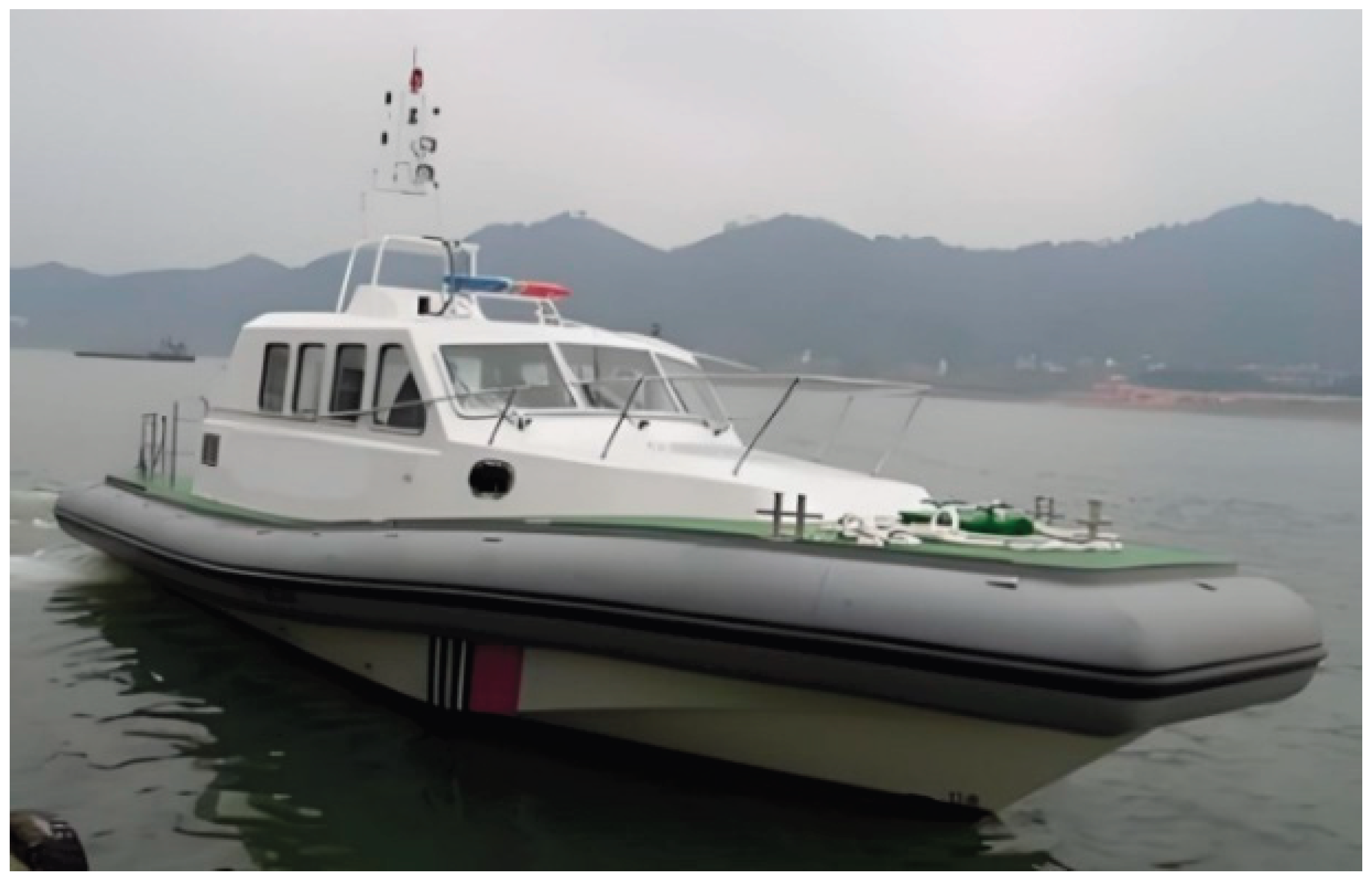
Figure 2.
Schematic of the methanol-electric hybrid propulsion system architecture for marine applications.
Figure 2.
Schematic of the methanol-electric hybrid propulsion system architecture for marine applications.
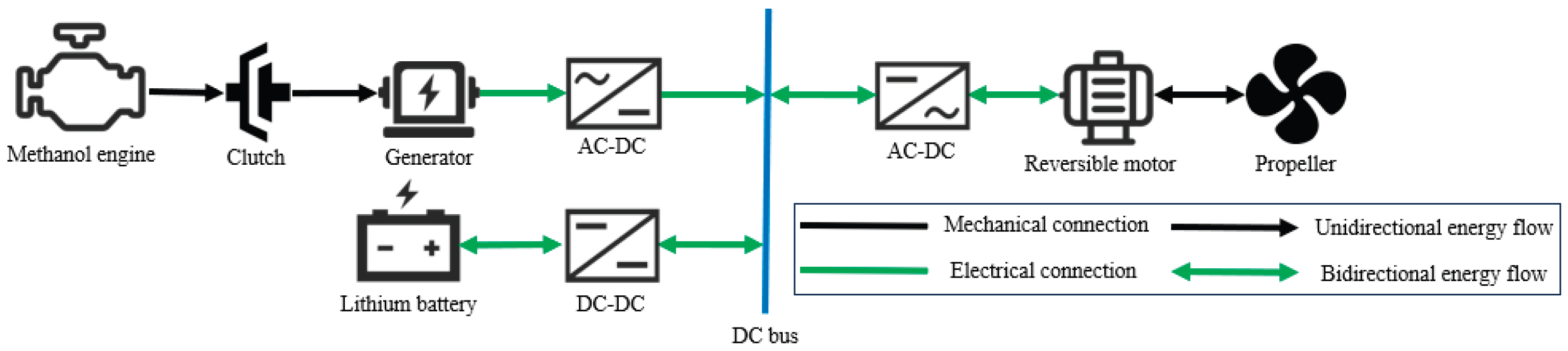
Figure 3.
Energy flow diagram of the all-electric propulsion mode.
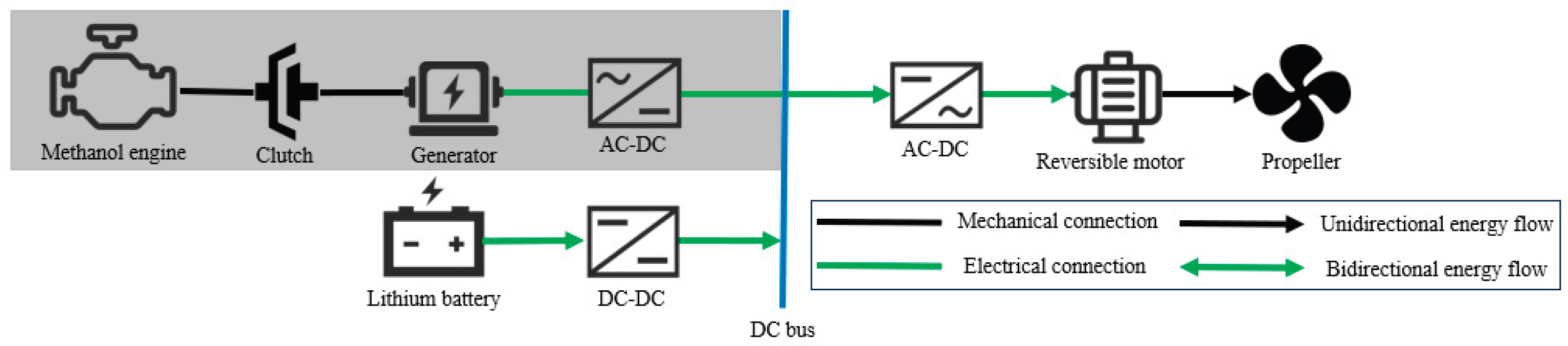
Figure 4.
Energy flow diagram of the methanol range-extended propulsion mode.
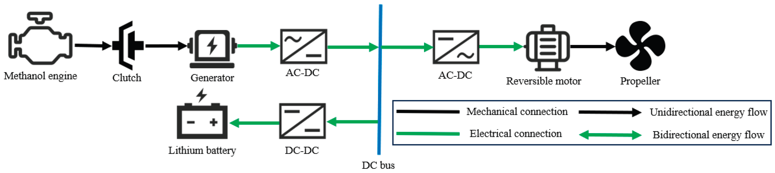
Figure 5.
Energy flow diagram of the hybrid propulsion mode.
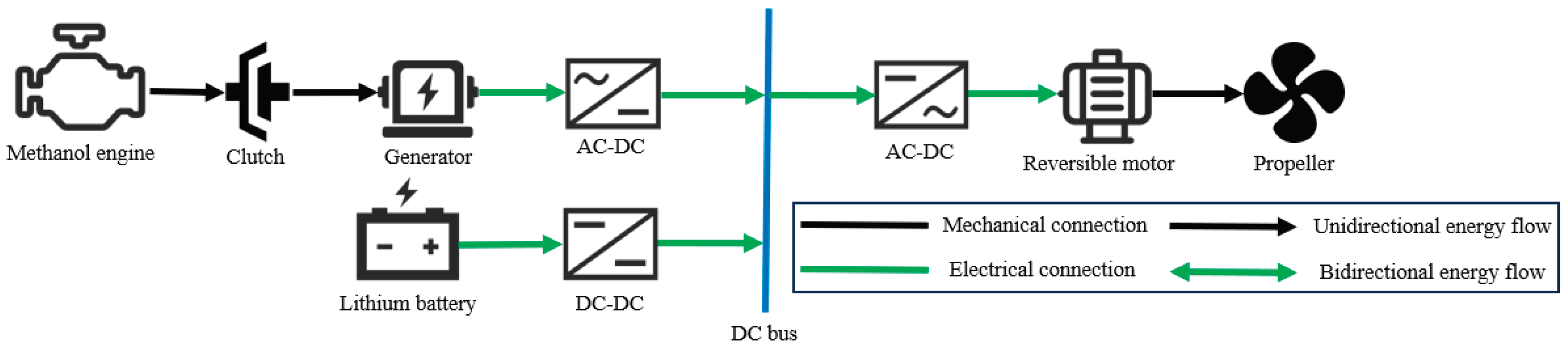
Figure 6.
Energy flow diagram of the regenerative braking mode.
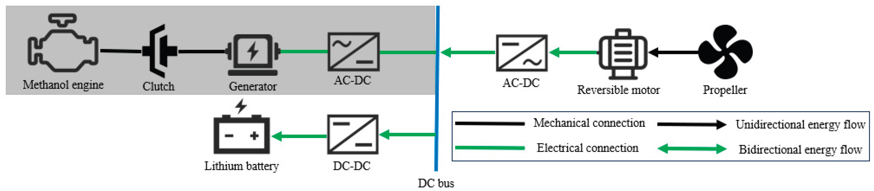
Figure 7.
Operational mode transition logic diagram.
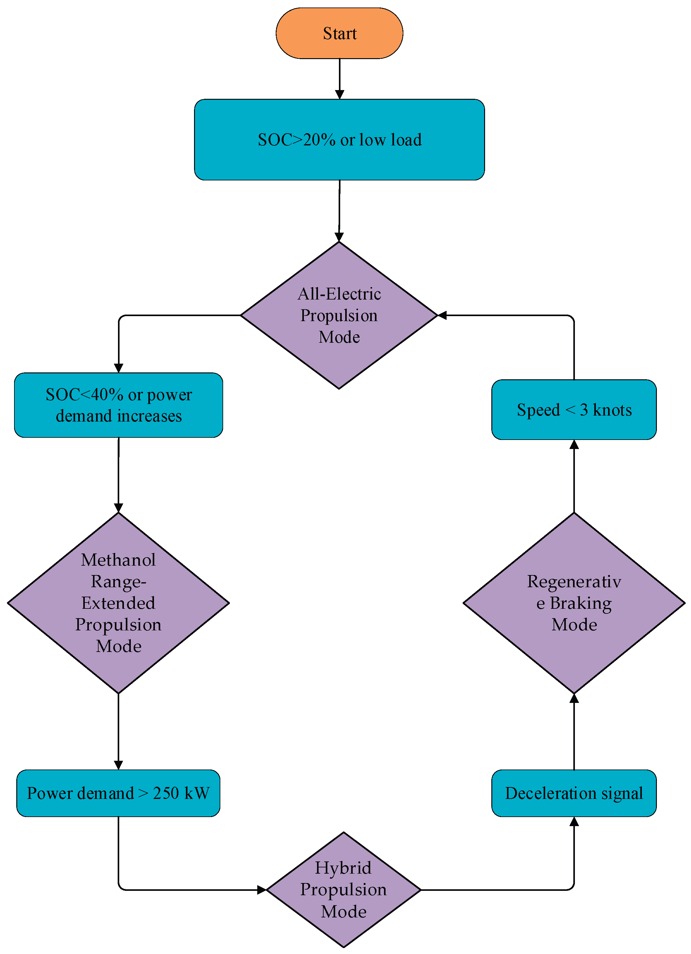
Figure 8.
Methanol engine bench test setup.
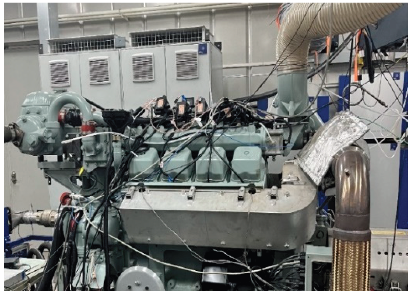
Figure 9.
Engine power MAP of the methanol engine.
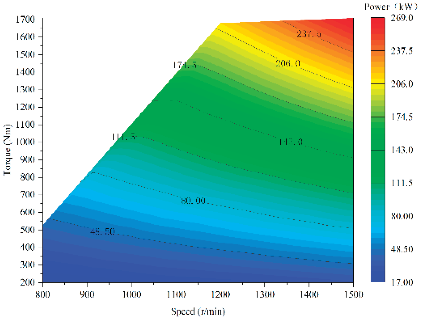
Figure 10.
Methanol consumption MAP of the methanol engine.
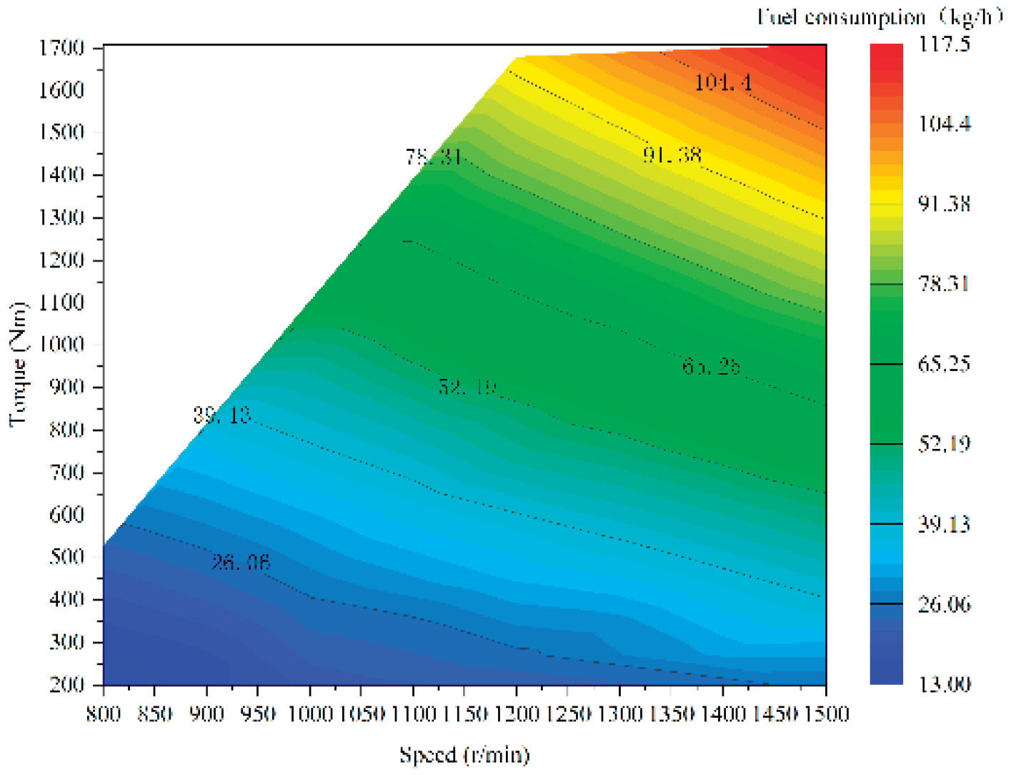
Figure 11.
Brake-specific fuel consumption (BSFC) MAP of the methanol engine.
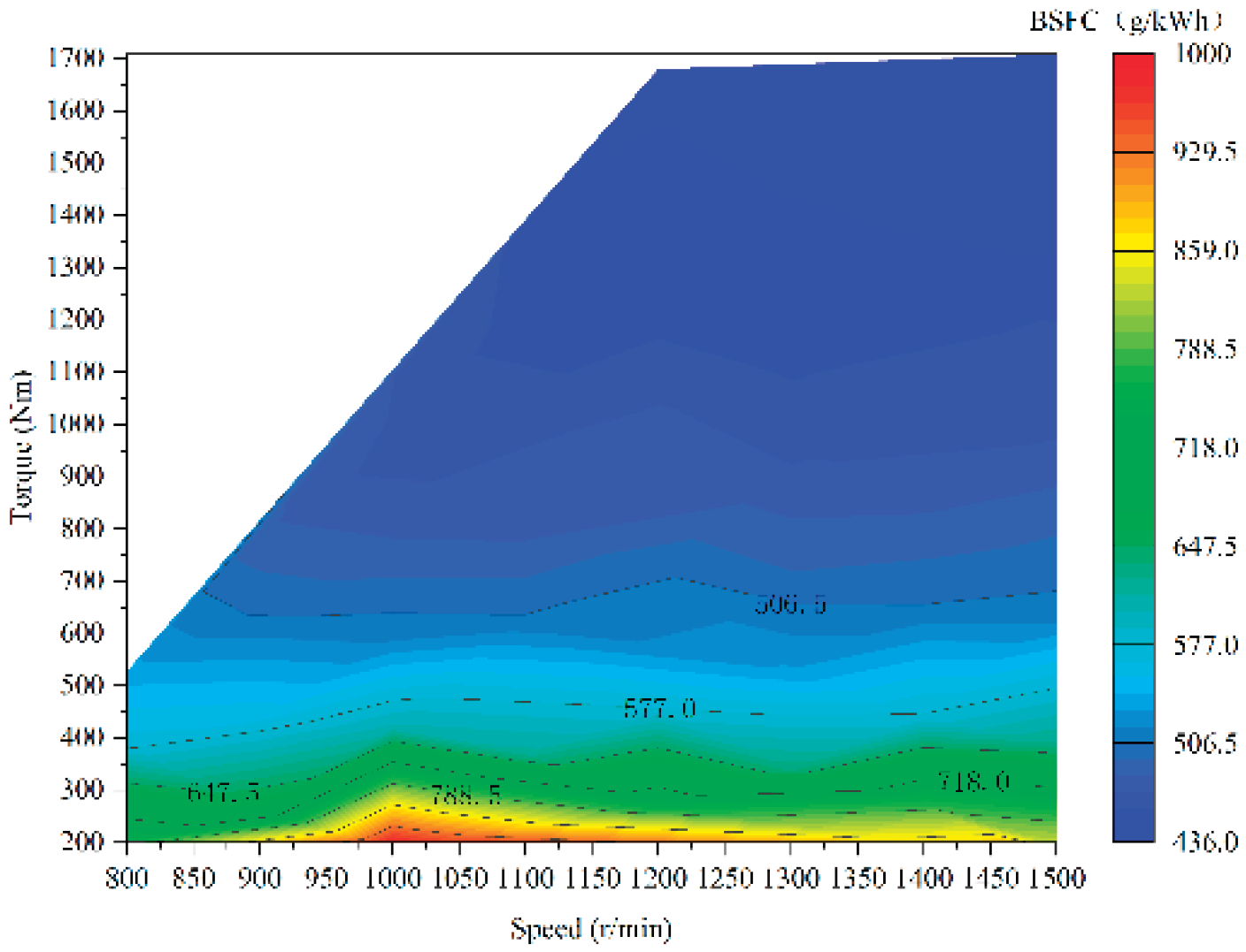
Figure 12.
CO emission MAP of the methanol engine.
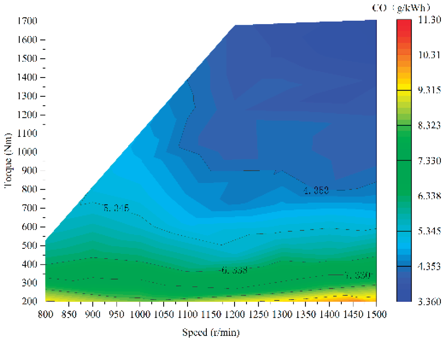
Figure 13.
CO₂ emission MAP of the methanol engine.
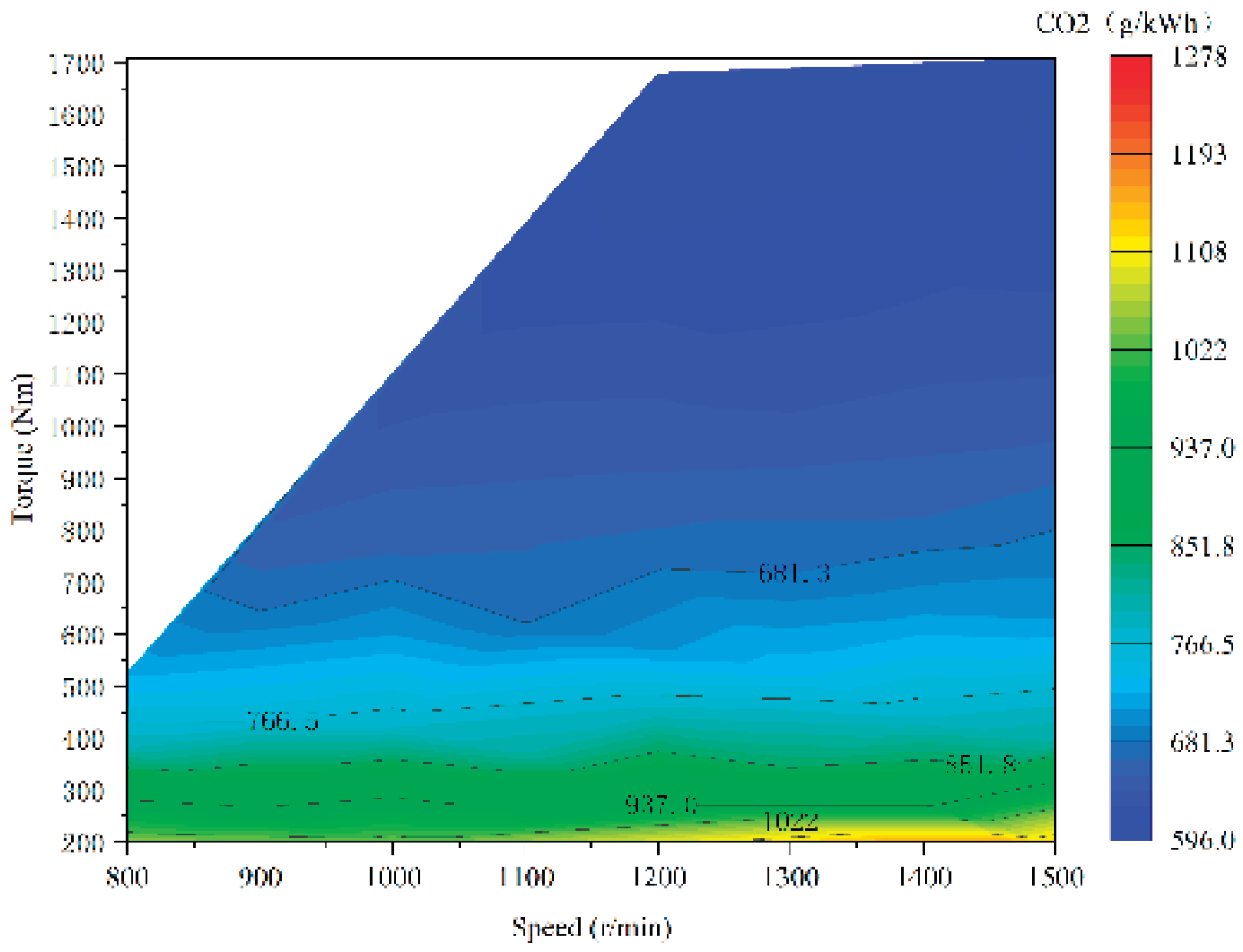
Figure 14.
HC emission MAP of the methanol engine.
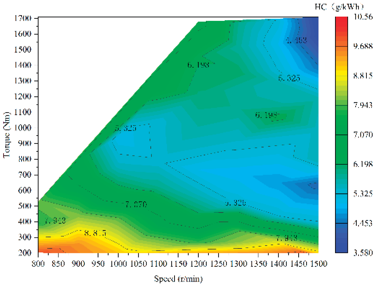
Figure 15.
NOx emission MAP of the methanol engine.
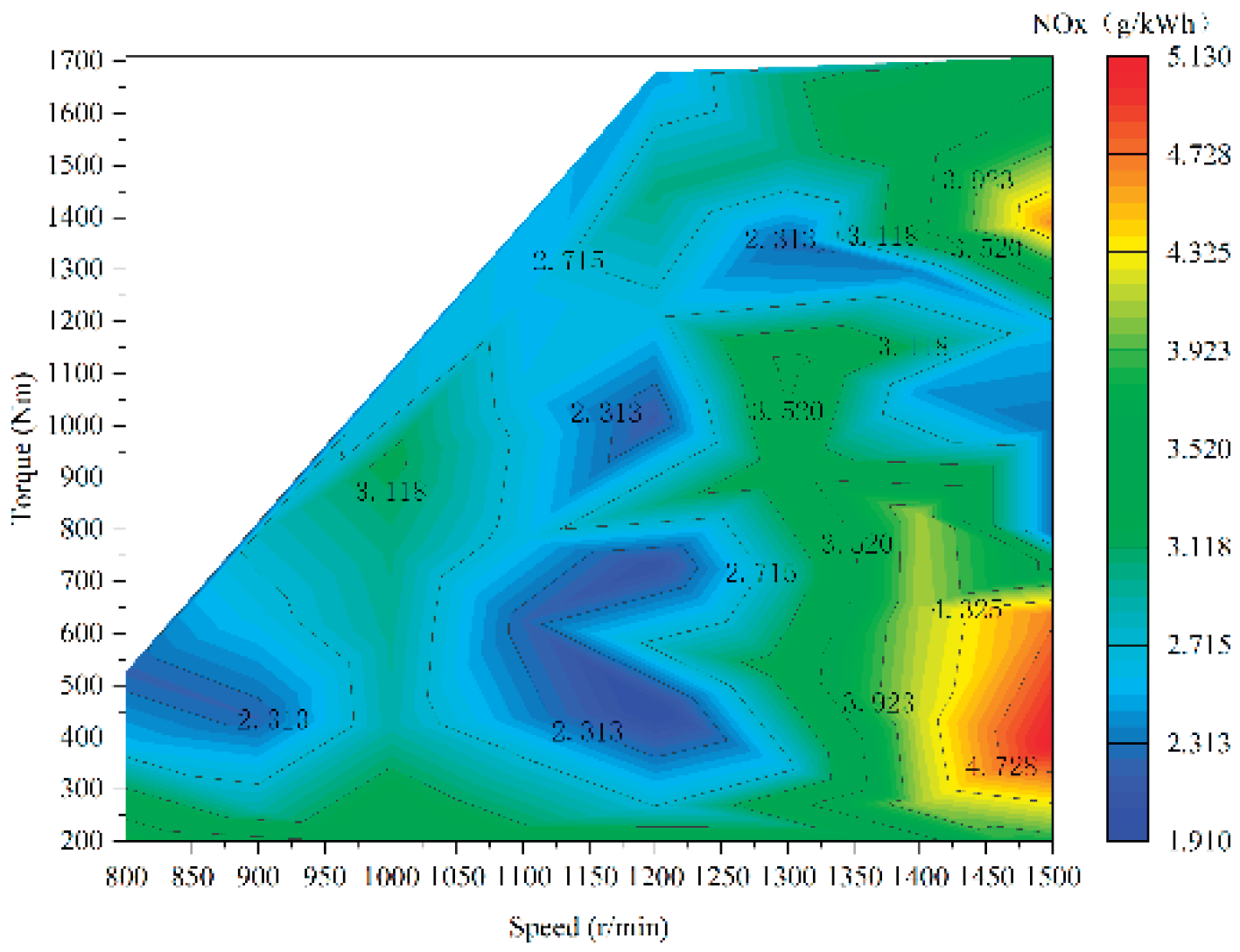
Figure 16.
Simulation model of the marine methanol-electric hybrid propulsion system.
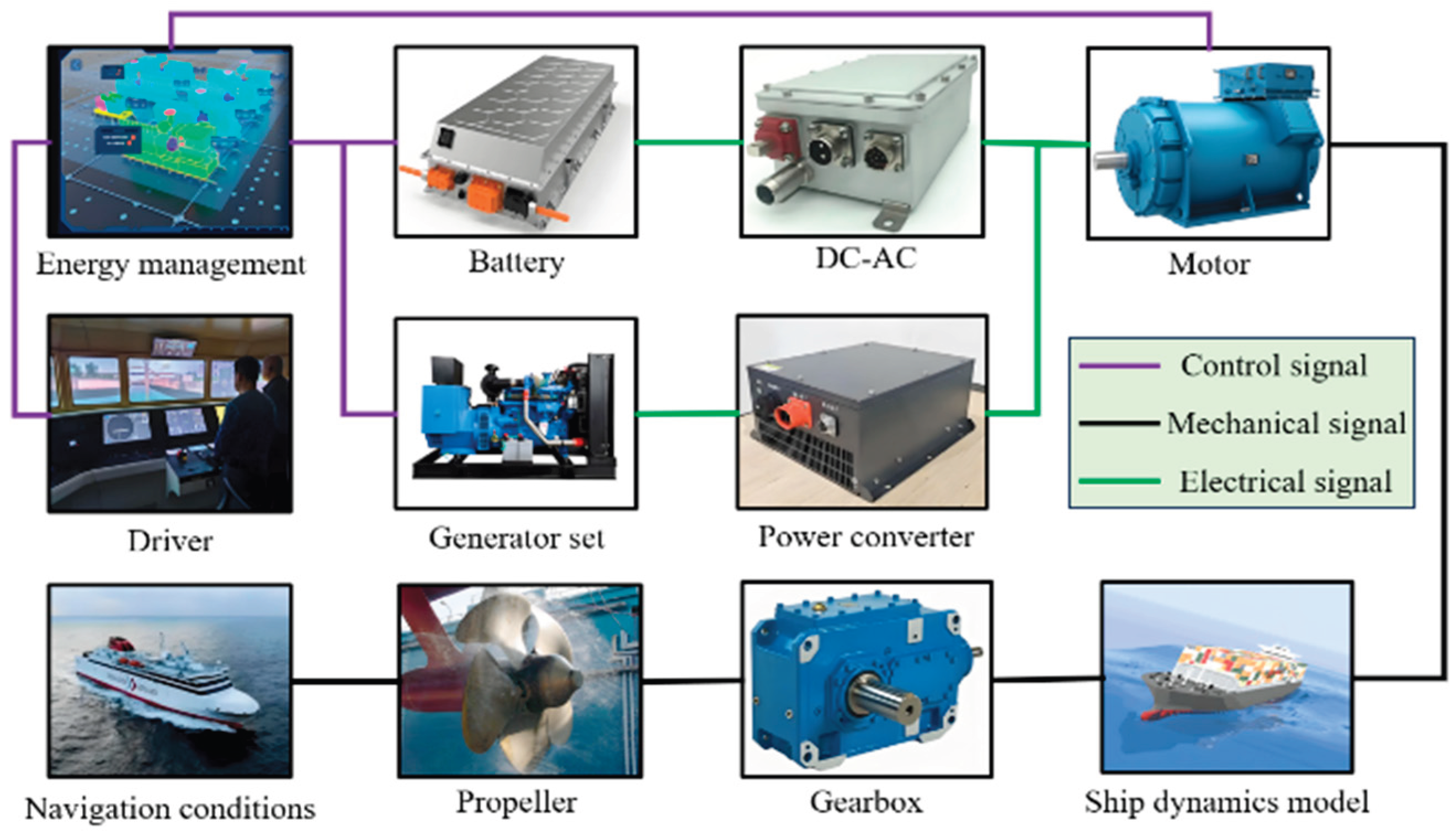
Figure 18.
Flowchart of the rule-based energy management strategy.
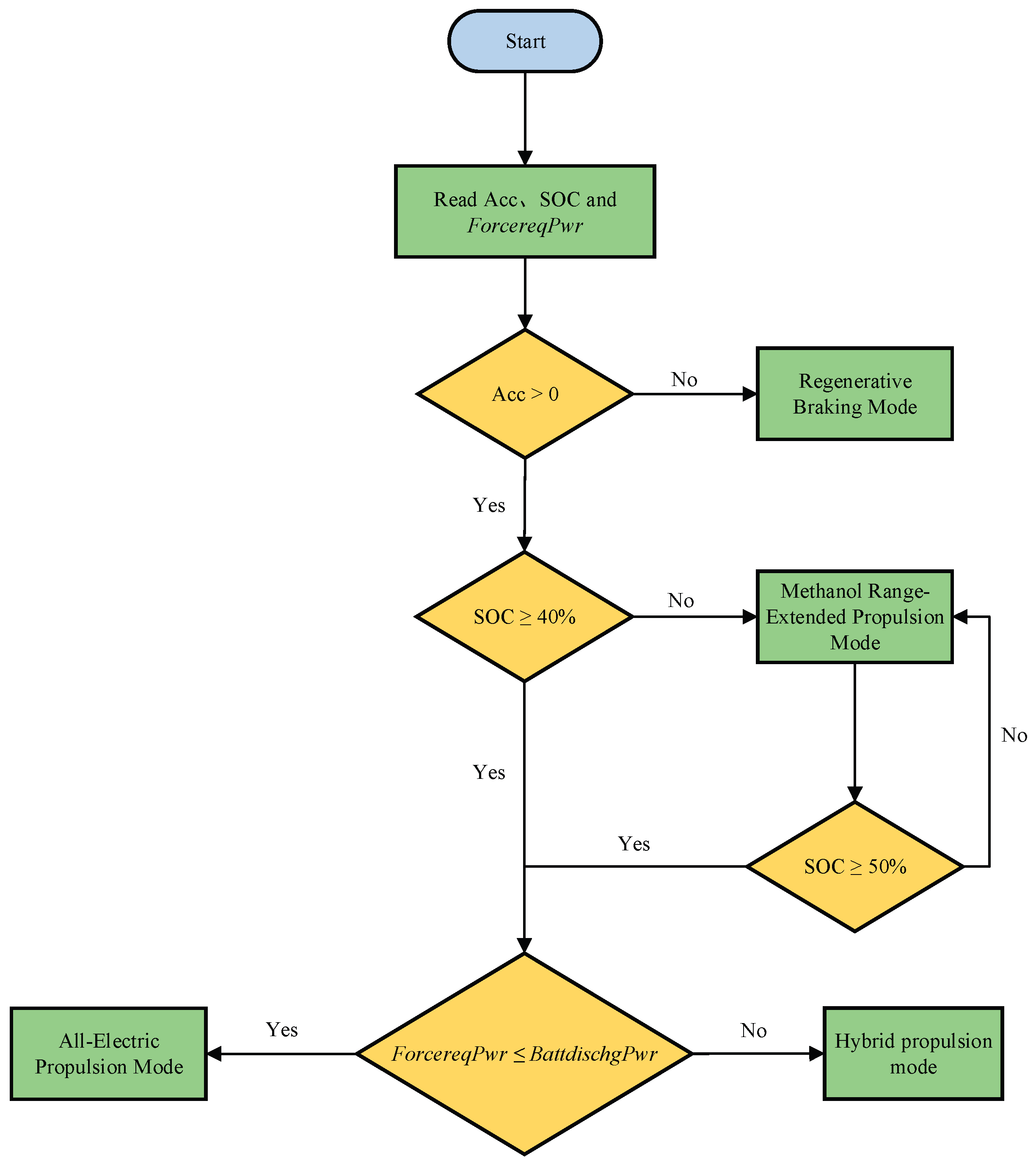
Figure 19.
Dynamic programming-based energy management strategy.
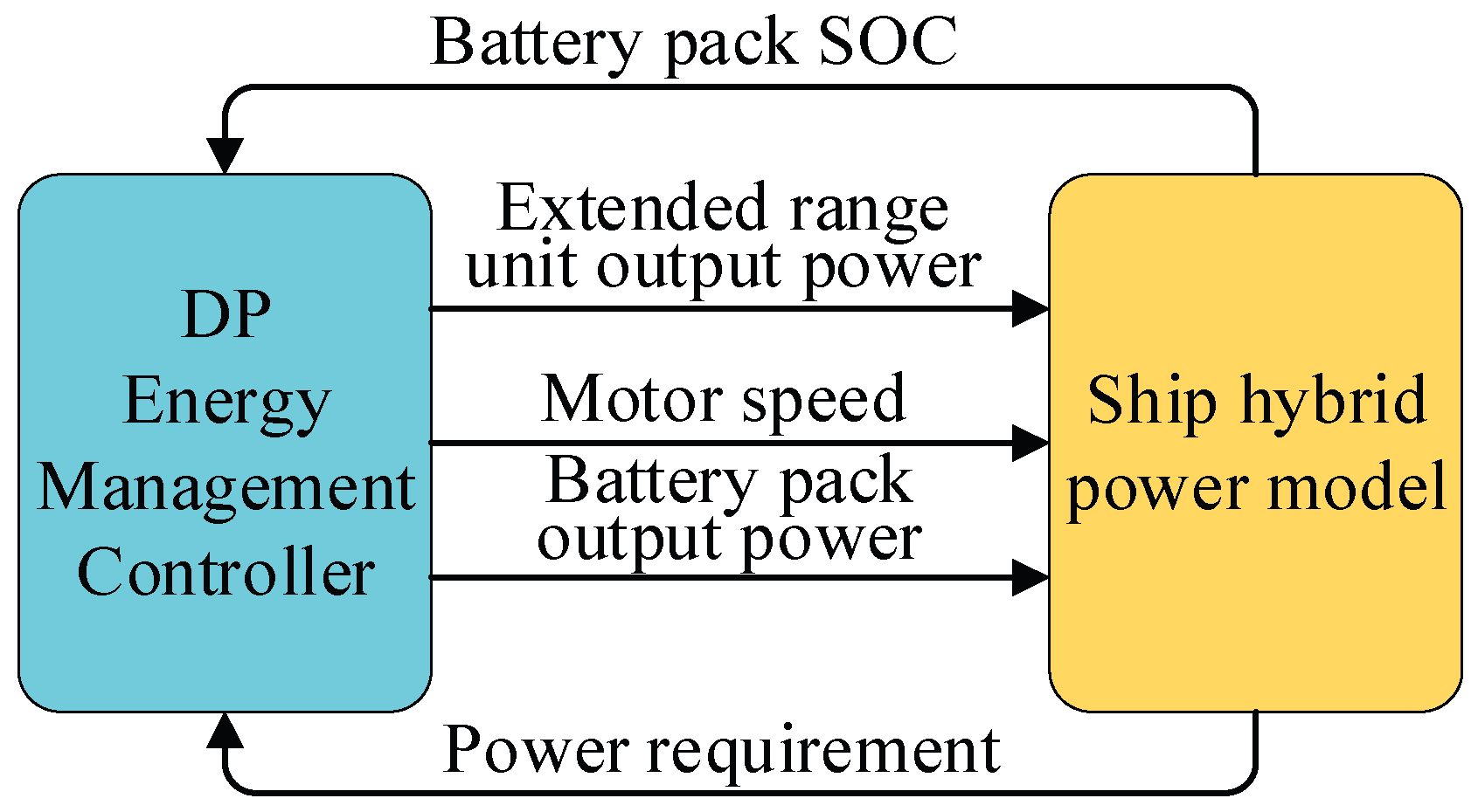
Figure 20.
Dynamic programming solution procedure.
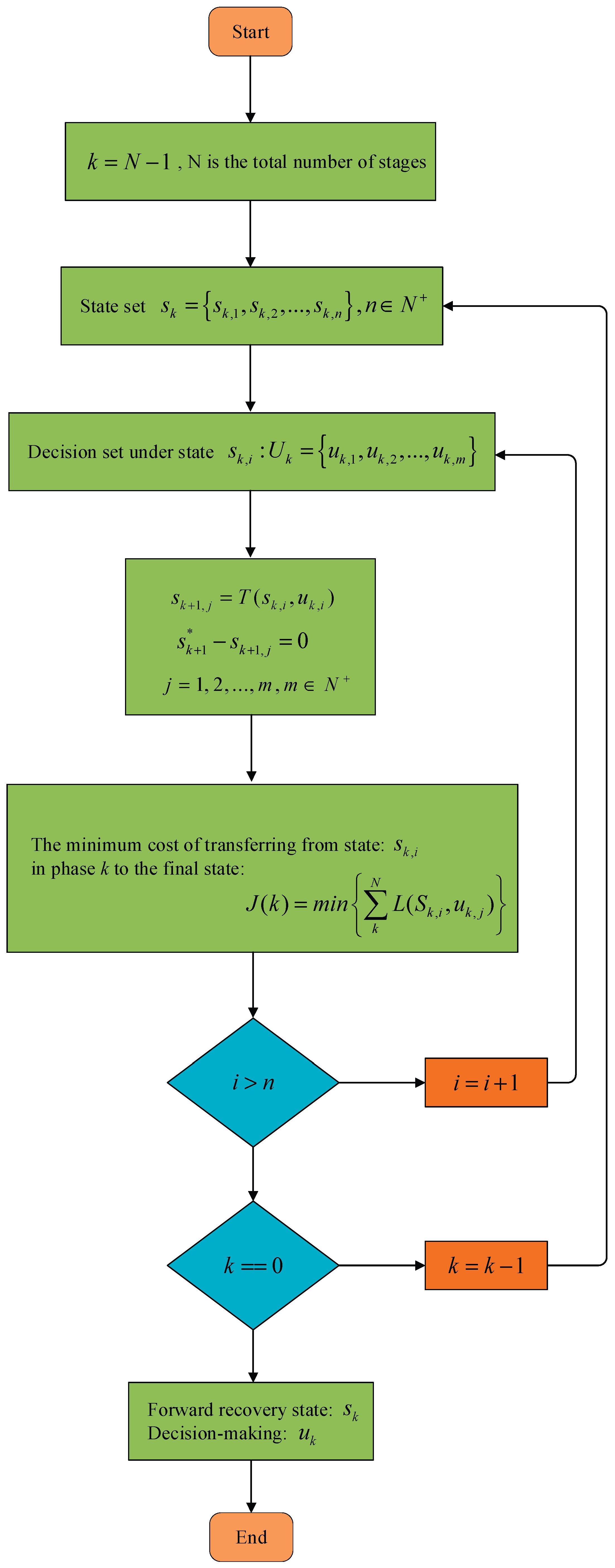
Figure 21.
Architecture of the Sugeno-type ANFIS.
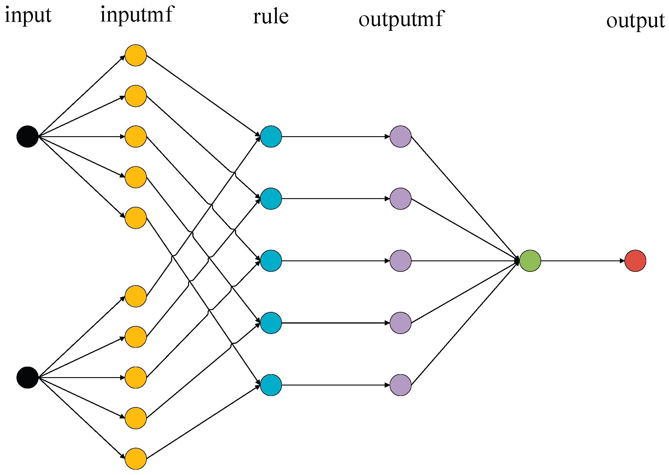
Figure 22.
Training error convergence curve.
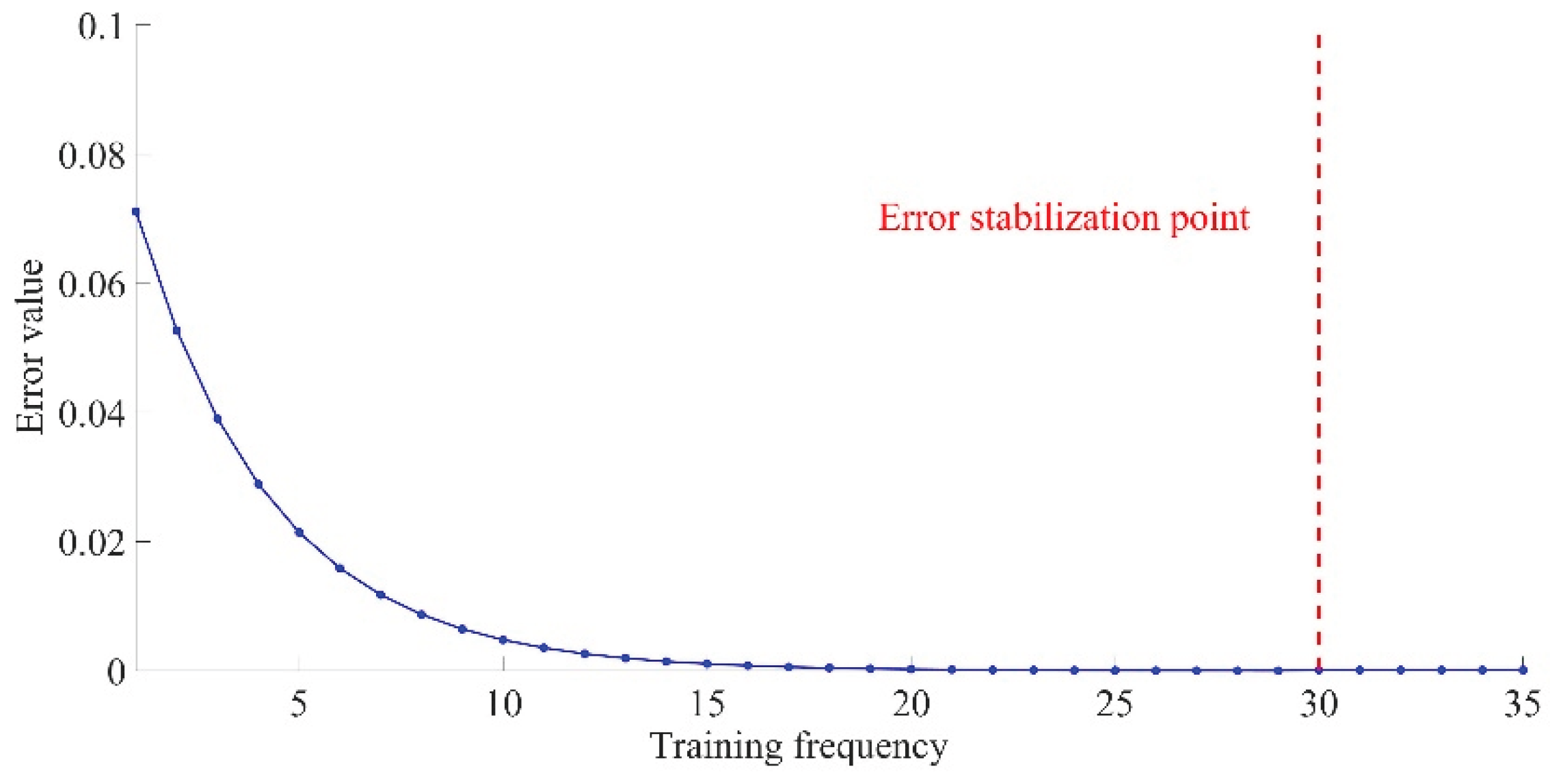
Figure 23.
Membership functions of the required power.
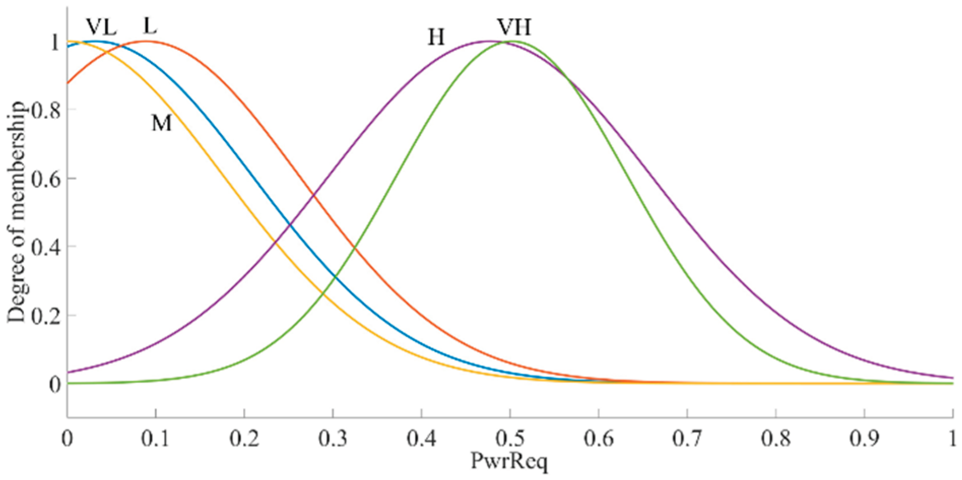
Figure 24.
Membership functions of the battery pack SOC.
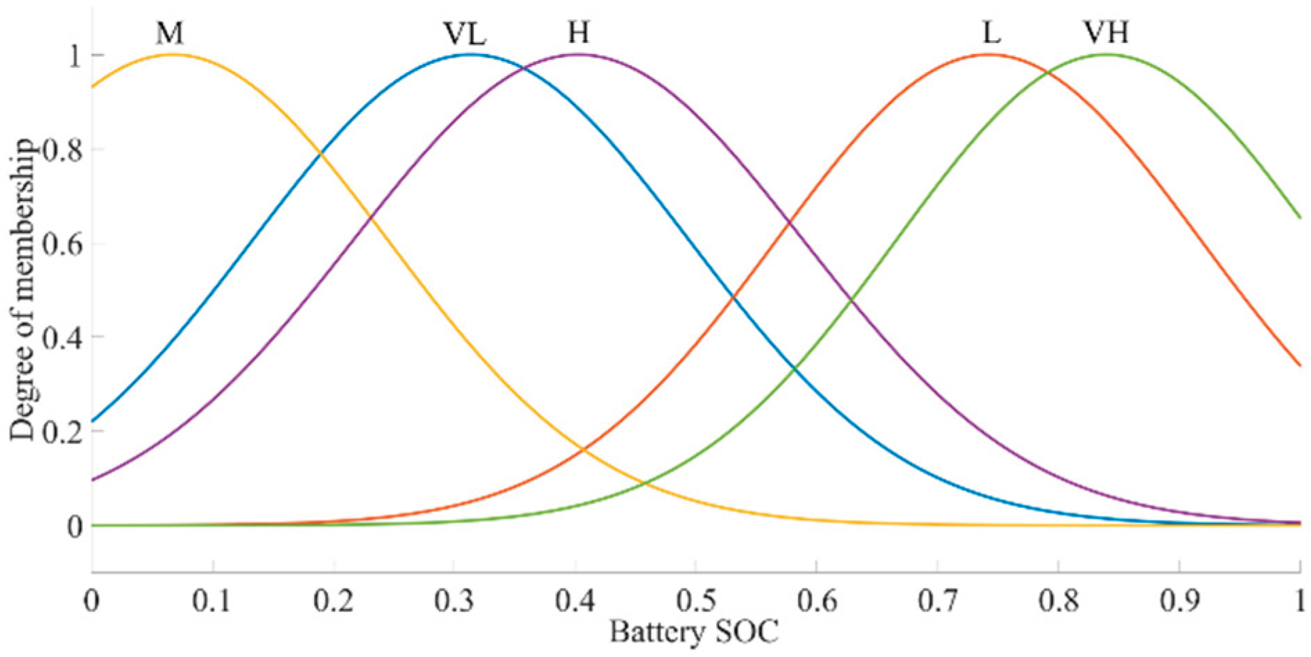
Figure 25.
Output surface of methanol engine power based on fuzzy rules.
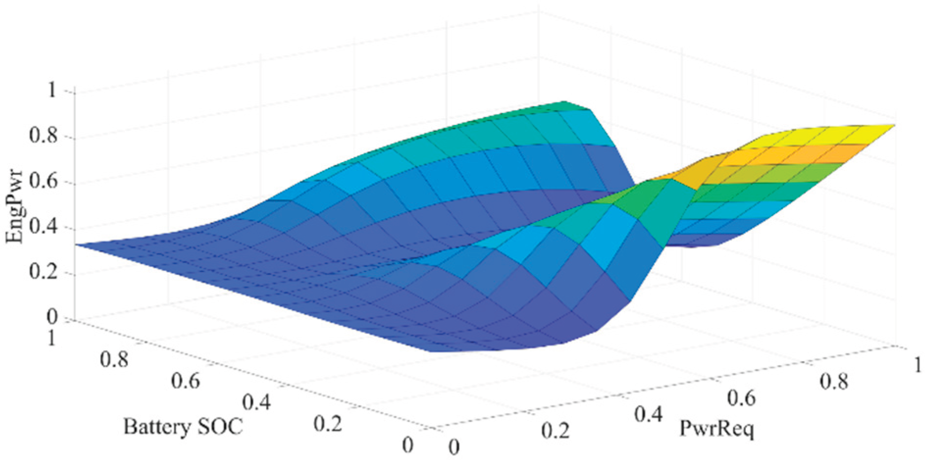
Figure 26.
Methanol consumption profile.
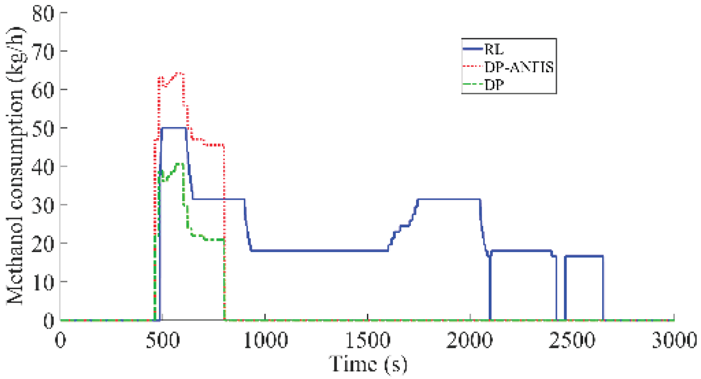
Figure 27.
Brake-specific fuel consumption (BSFC) profile.
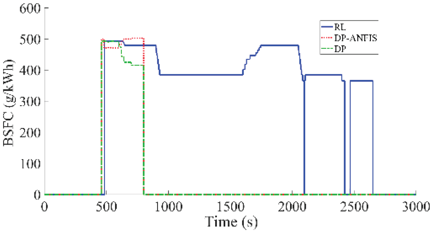
Figure 28.
Battery state of charge (SOC) variation.
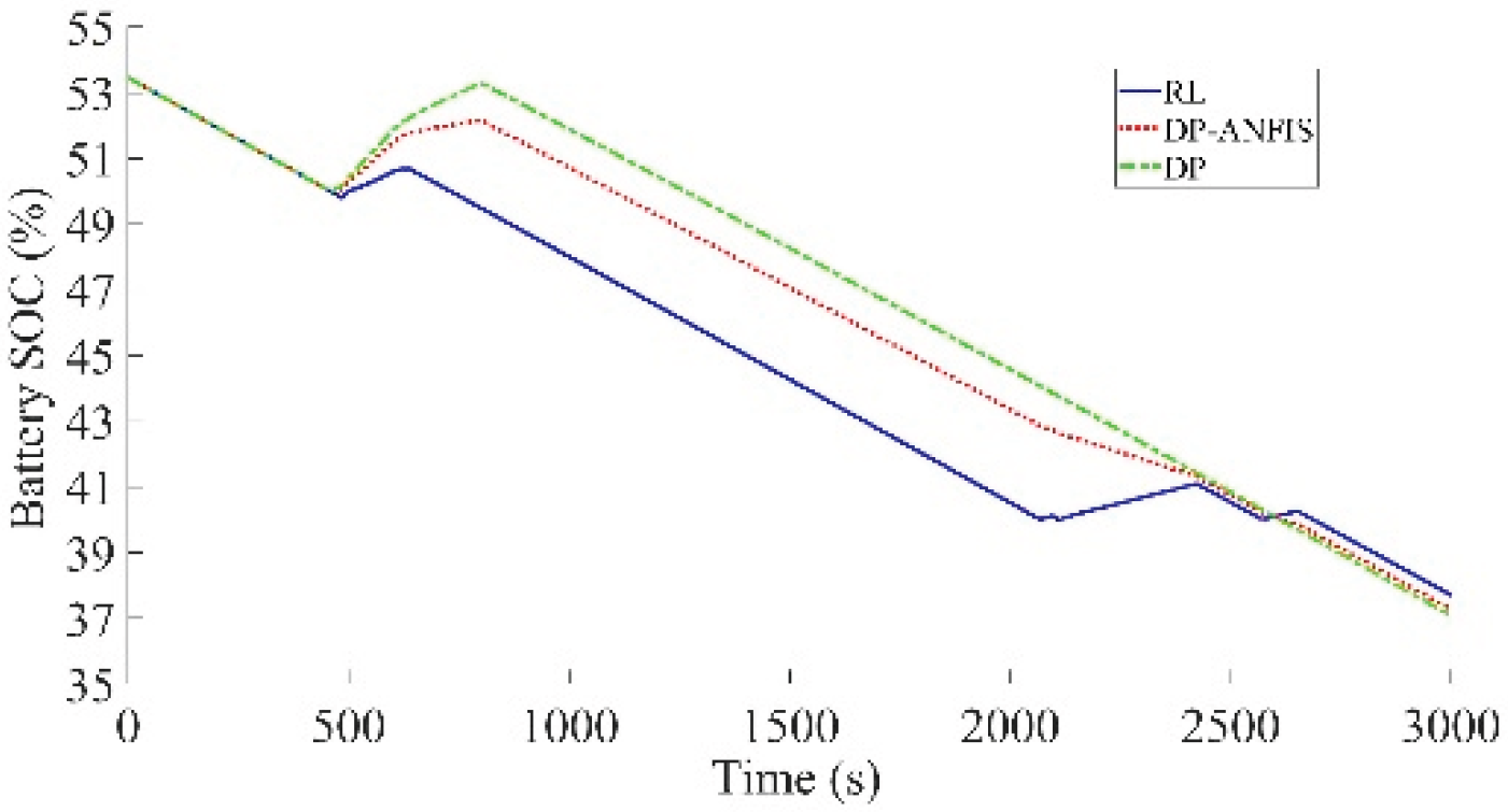
Figure 29.
CO emission profile.
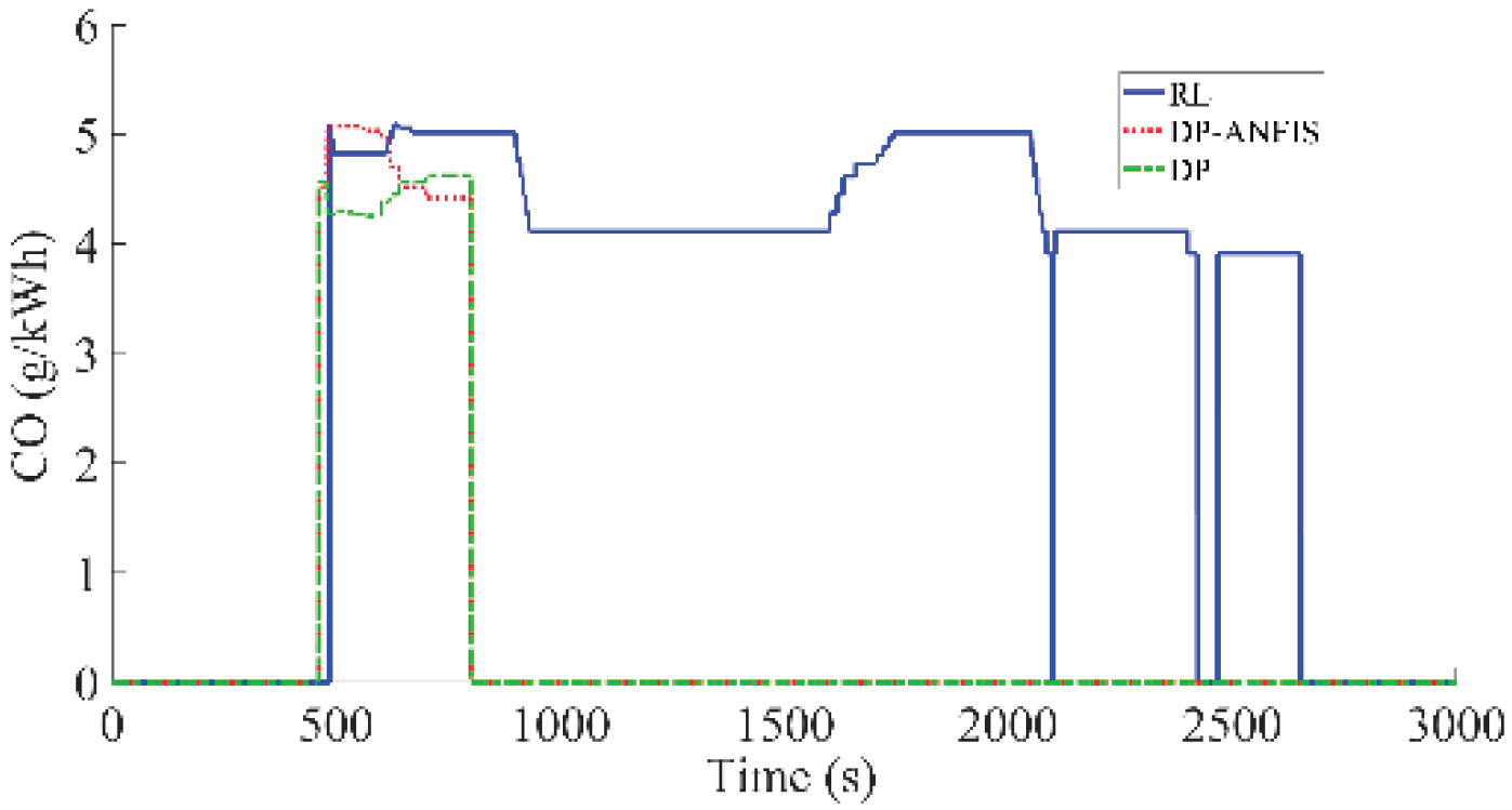
Figure 30.
CO₂ emission profile.
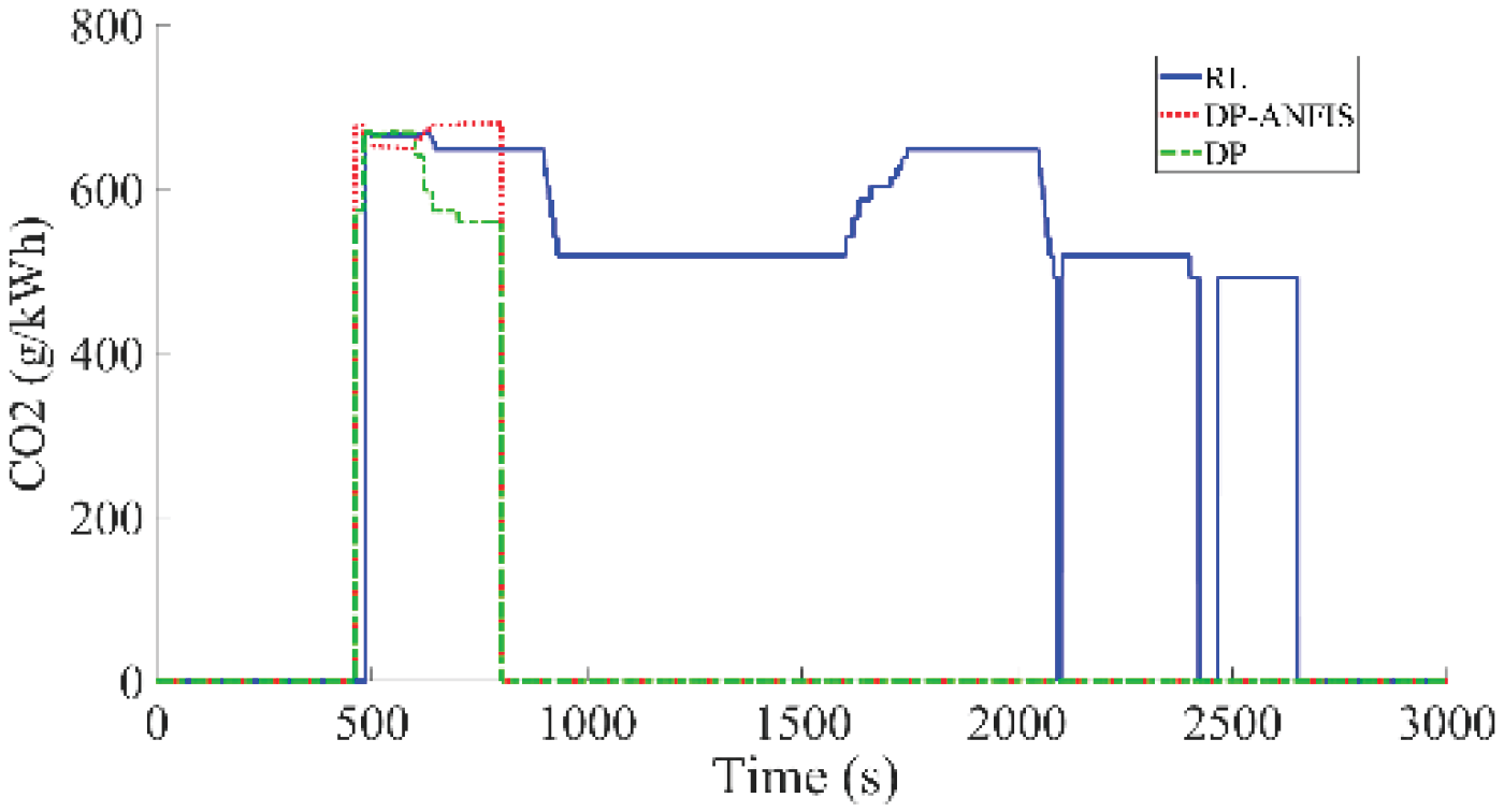
Figure 31.
HC emission profile.
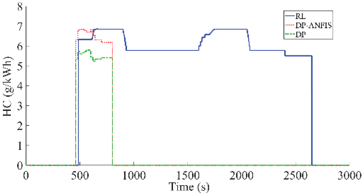
Figure 32.
NOx emission profile.
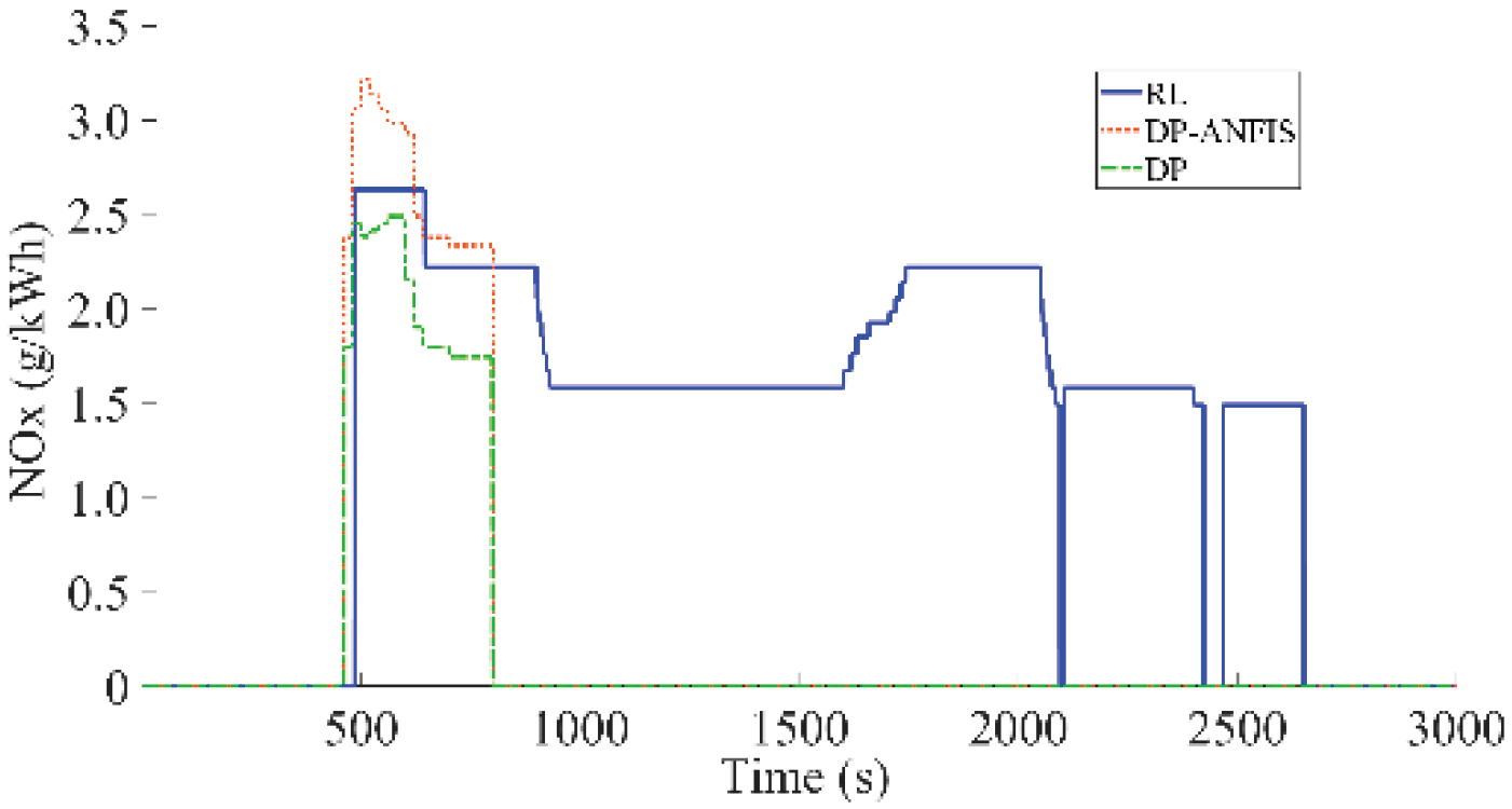
Figure 33.
Methanol consumption comparison.
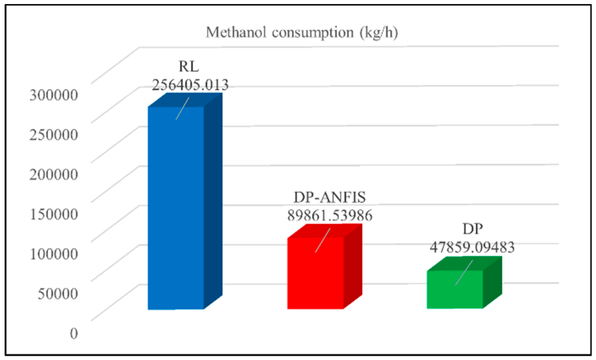
Figure 34.
Brake-specific fuel consumption (BSFC) comparison.
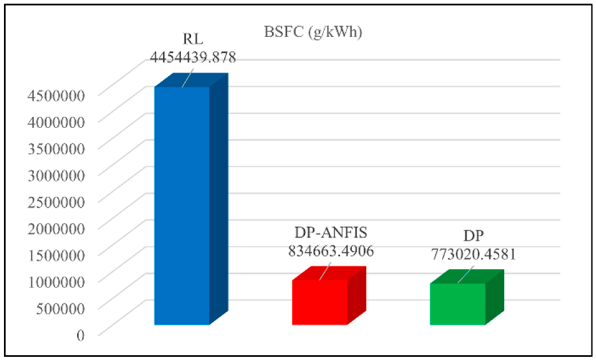
Figure 35.
Battery pack SOC comparison.
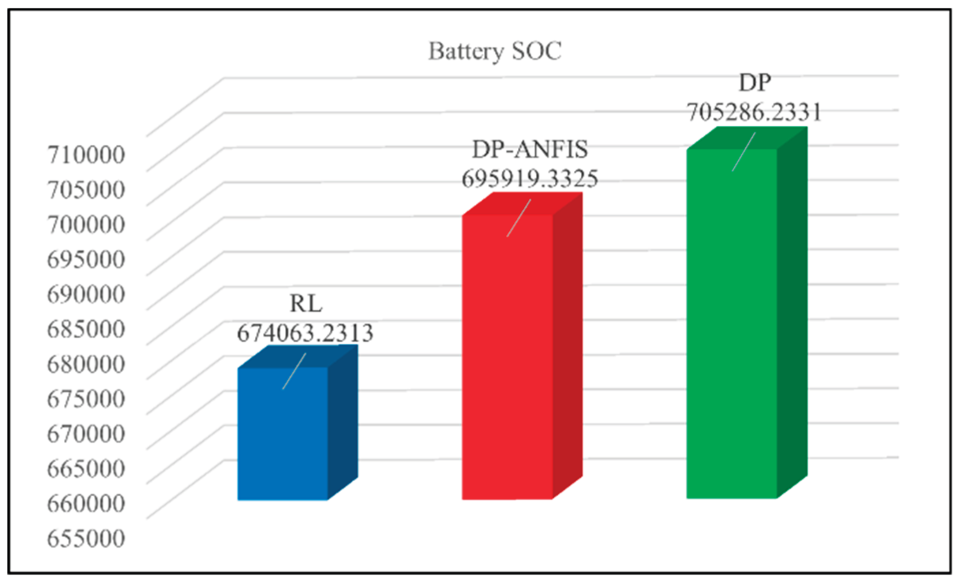
Figure 36.
CO emission comparison.
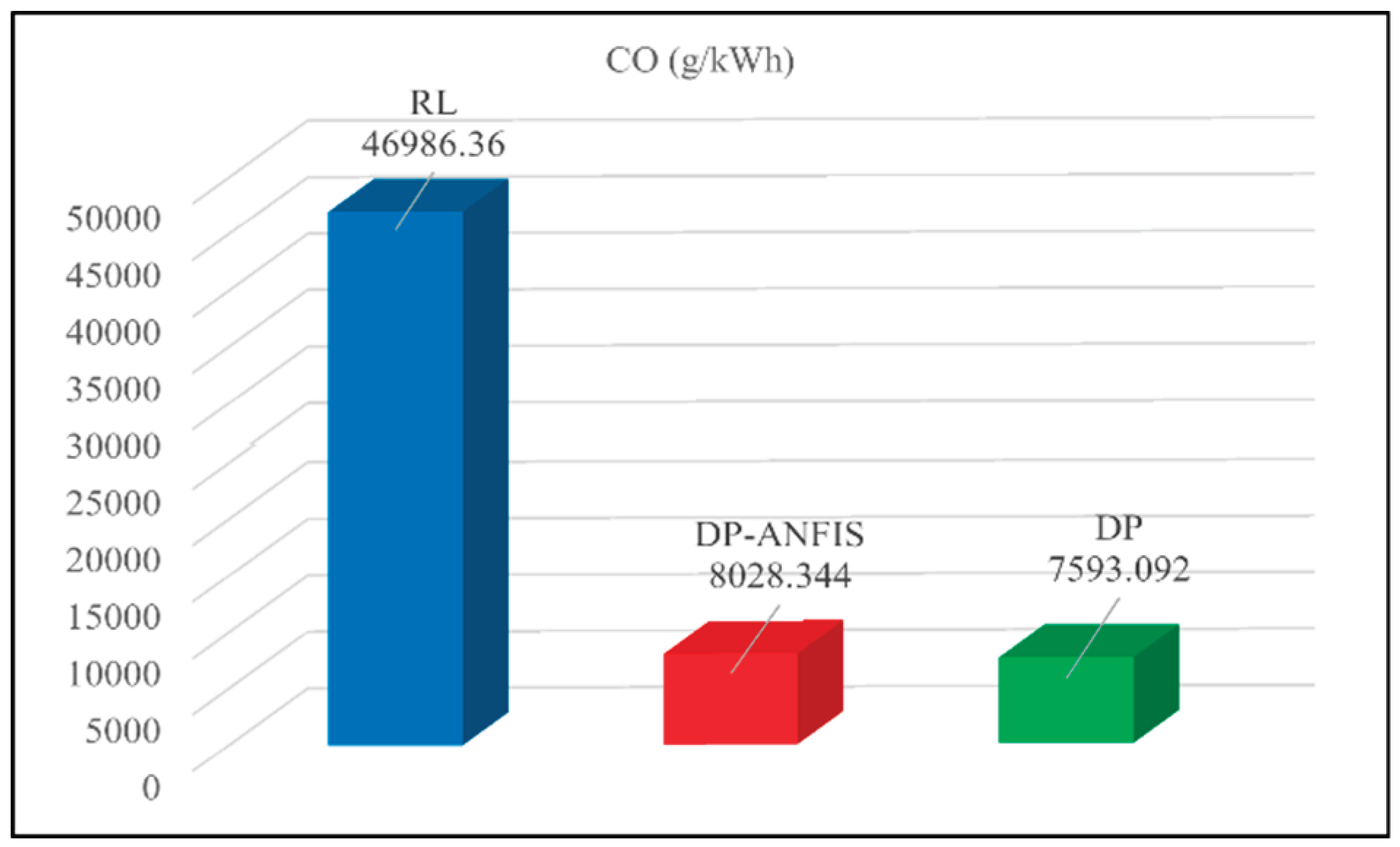
Figure 37.
CO2 emission comparison.
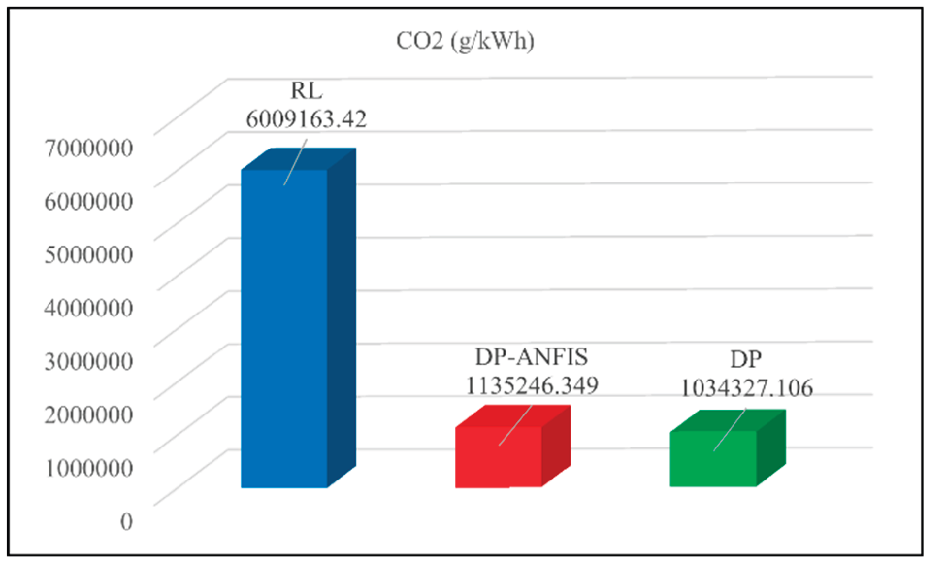
Figure 38.
HC emission comparison.
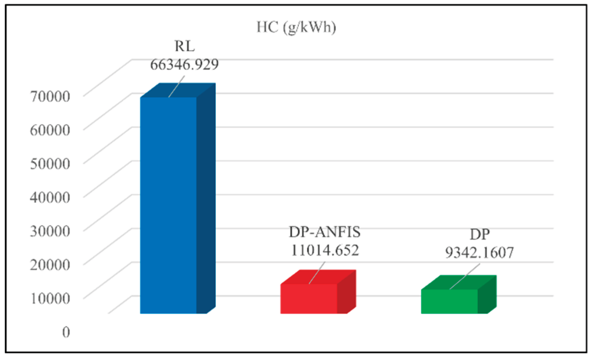
Figure 39.
NOx emission comparison.
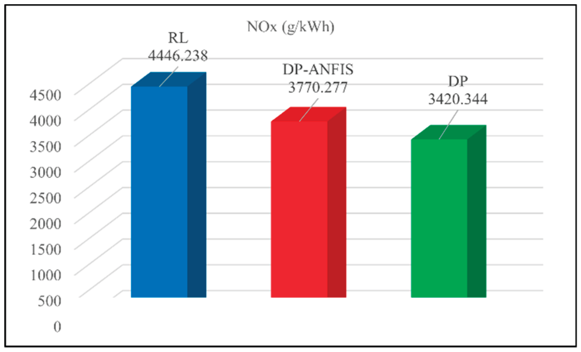
Figure 40.
Architecture of the distributed hardware-in-the-loop (HIL) platform for real-time validation of energy management strategies.
Figure 40.
Architecture of the distributed hardware-in-the-loop (HIL) platform for real-time validation of energy management strategies.
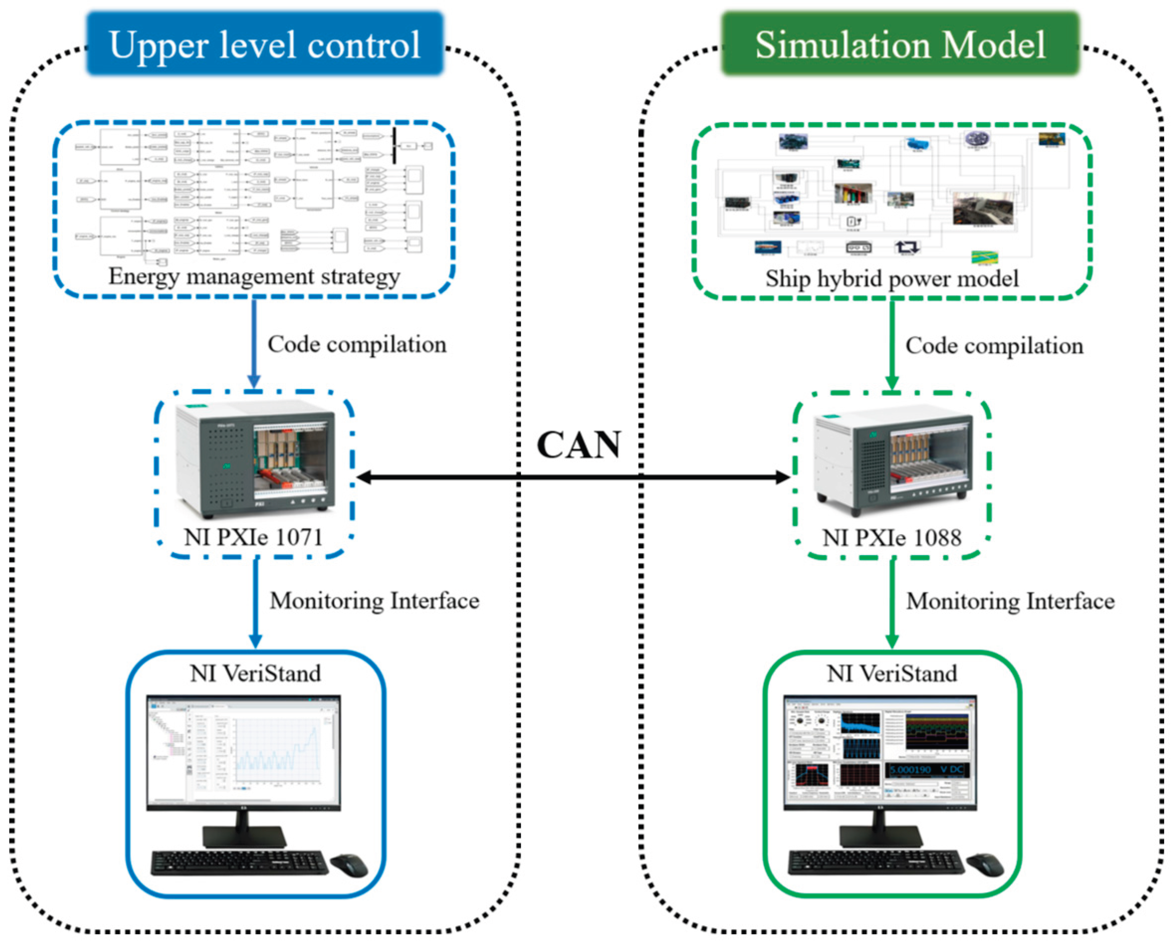
Figure 41.
Initial interface design of the NI VeriStand-based PC monitoring system.
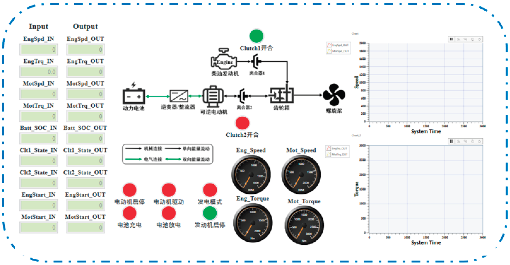
Figure 42.
HIL test bench for energy management strategy of the marine methanol-electric hybrid propulsion system.
Figure 42.
HIL test bench for energy management strategy of the marine methanol-electric hybrid propulsion system.

Figure 43.
Methanol consumption comparison: simulation vs. HIL test.
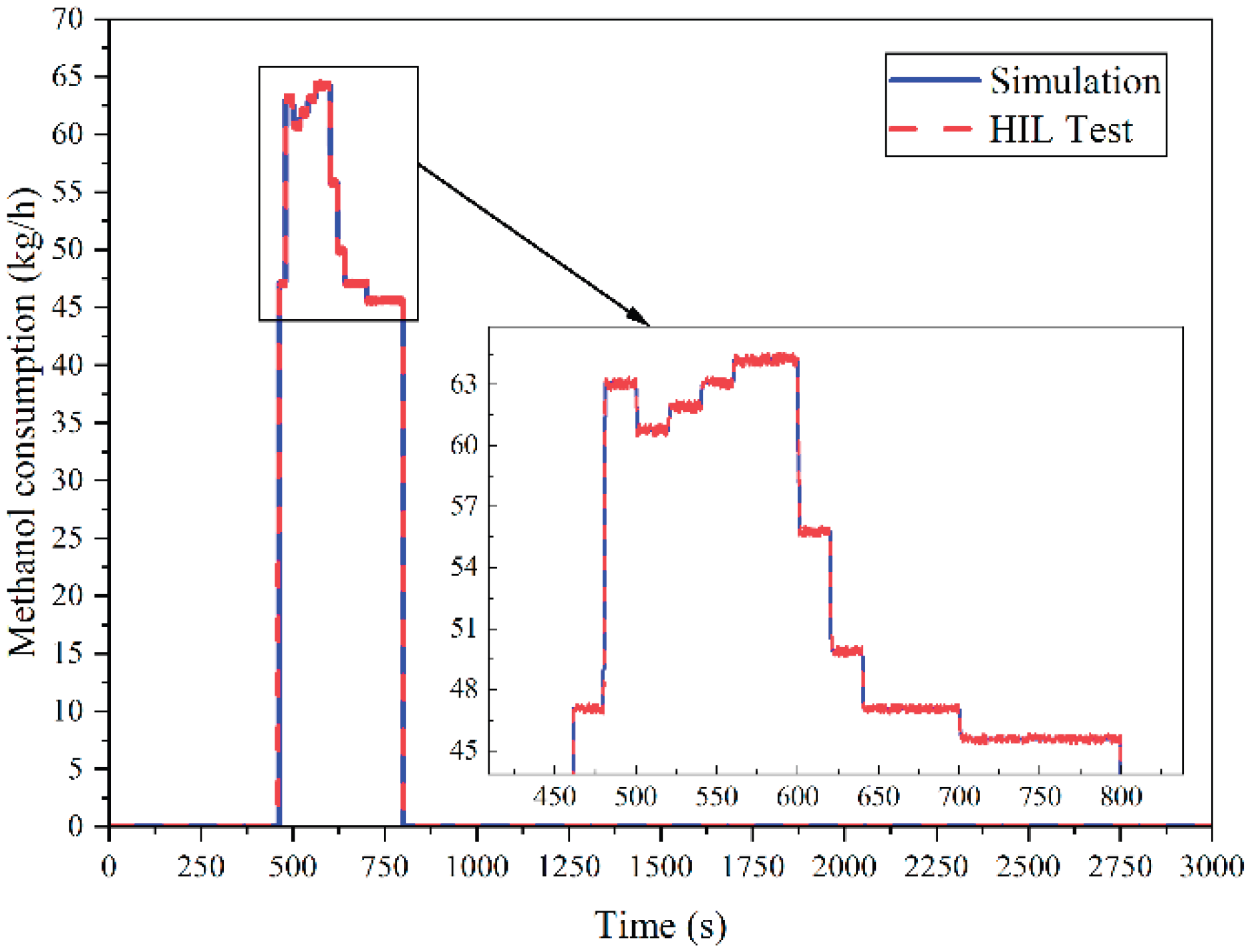
Figure 44.
Brake-specific fuel consumption (BSFC) comparison: simulation vs. HIL test.
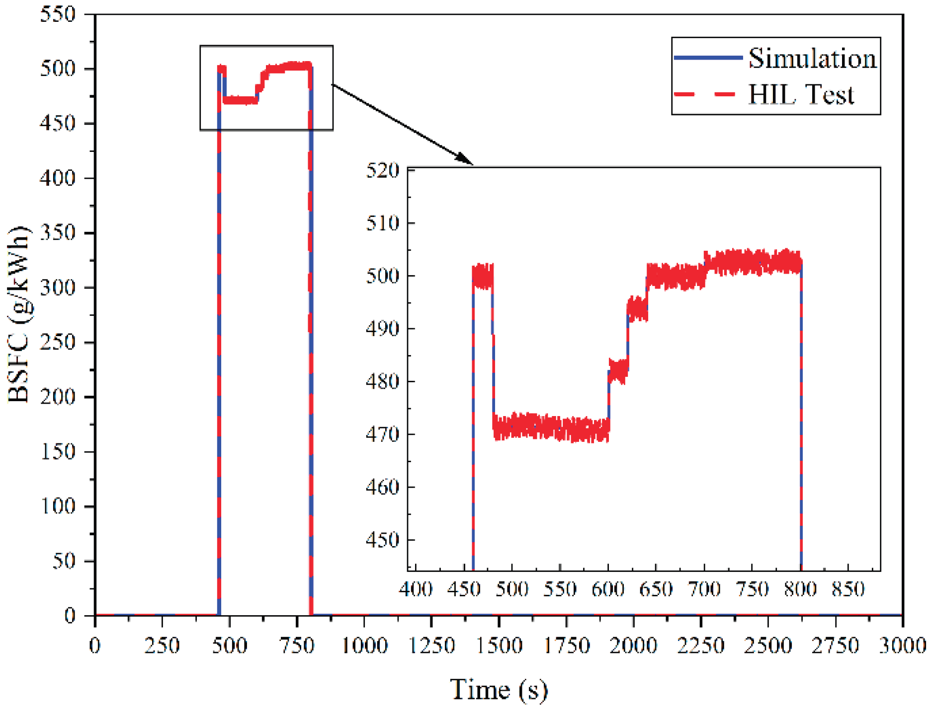
Figure 45.
Battery state of charge (SOC) comparison: simulation vs. HIL test.
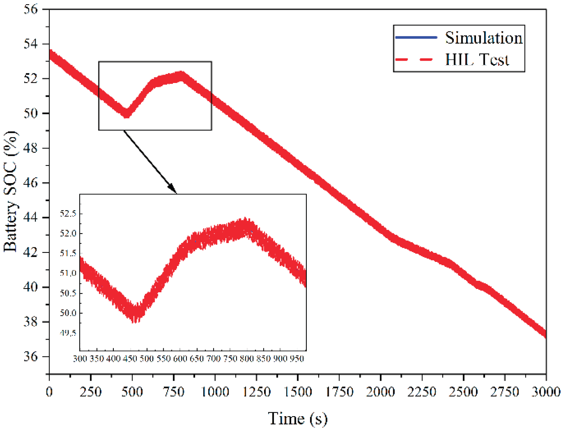
Figure 46.
CO emission comparison: simulation vs. HIL test.
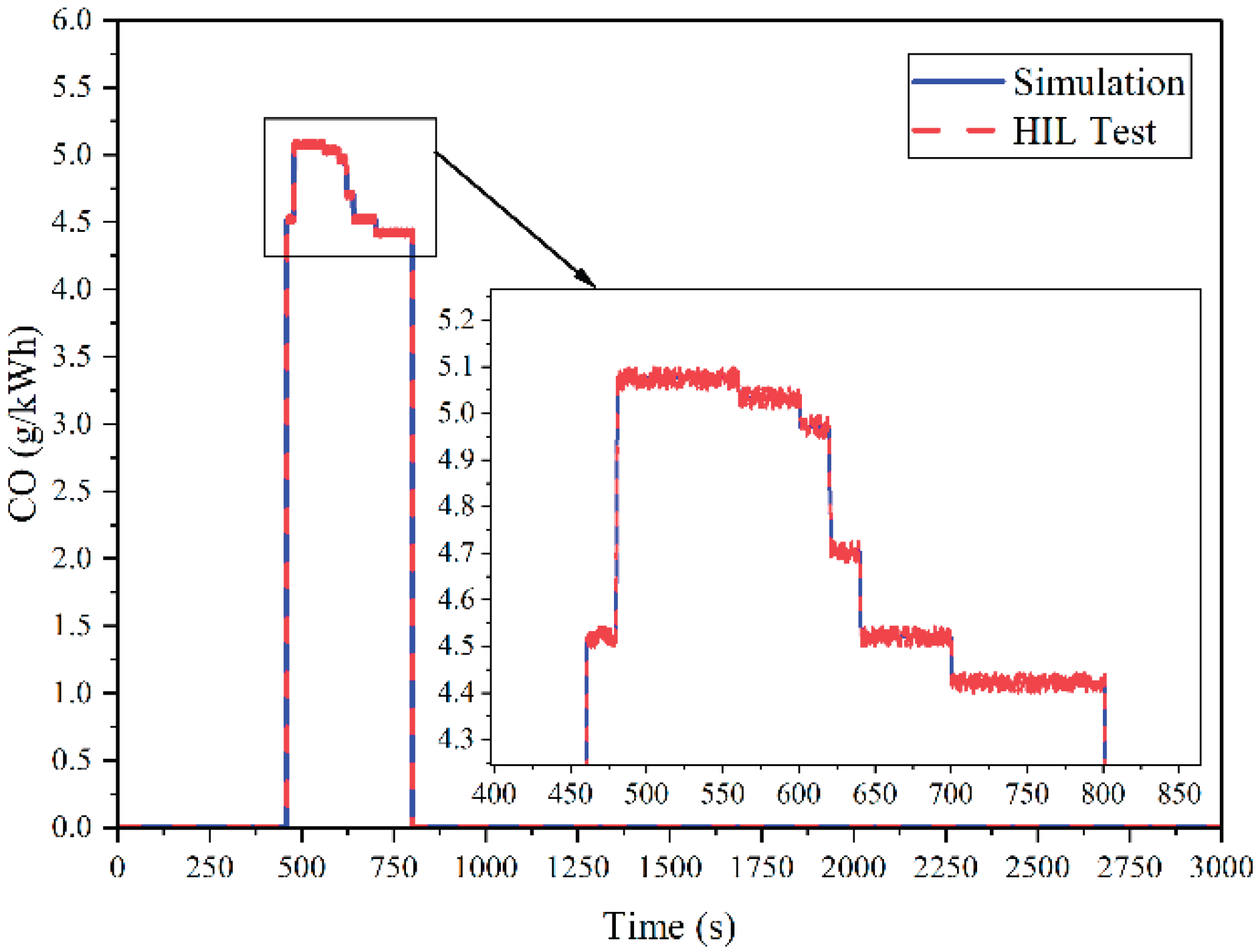
Figure 47.
CO2 emissions comparison: simulation vs. HIL test.
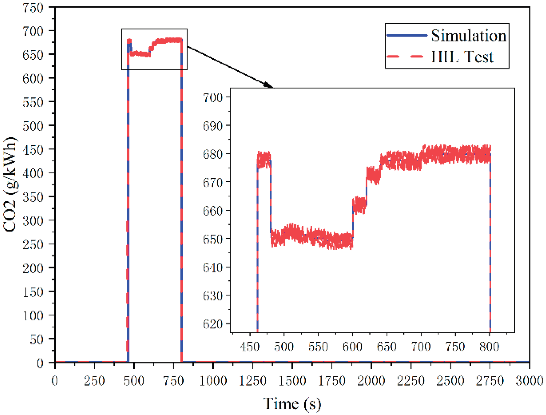
Figure 48.
HC emission comparison: simulation vs. HIL test.
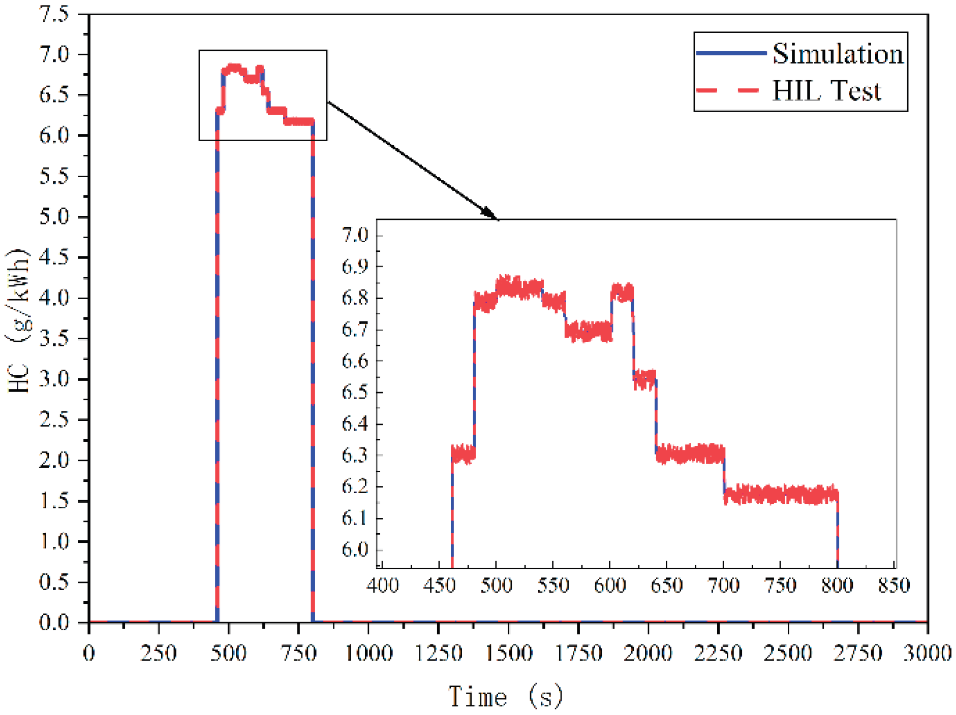
Figure 49.
NOx emission comparison: simulation vs. HIL test.
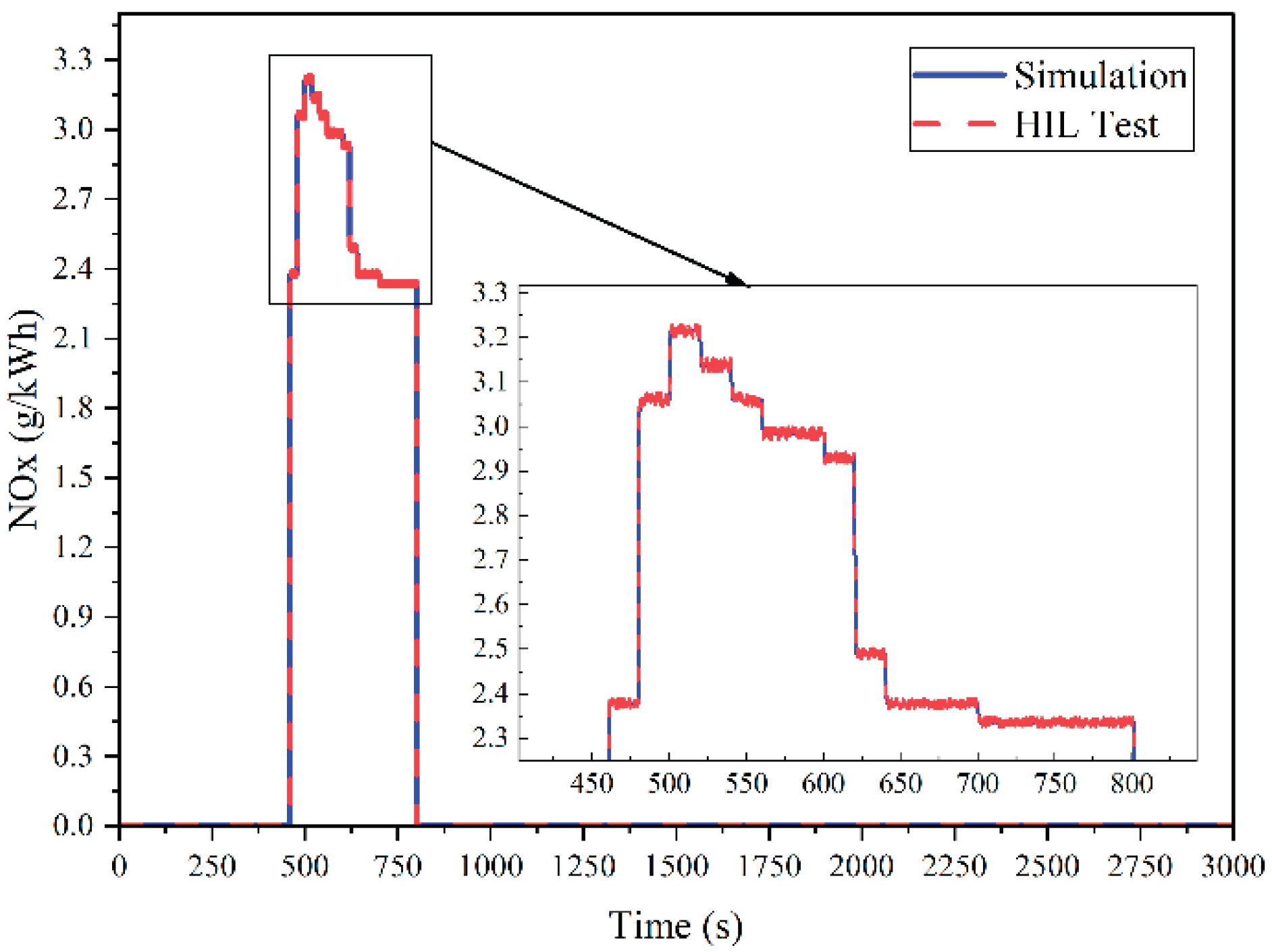

Table 1.
Key design parameters of the inland river law enforcement vessel.
| Parameters | Value |
|---|---|
| Length Overall | 25.5 m |
| Beam | 5.2 m |
| Draft | 1.5 m |
| Displacement | 80 t |
| Propeller Diameter | 0.9 m |
| Maximum Propeller Speed | 850 rpm |
| Maximum Speed | 22 km/h |
Table 2.
Key parameter configuration of the marine methanol-electric hybrid propulsion system.
| Power Components | Parameters | Value |
|---|---|---|
| Methanol Generator Set | Rated Power | 250 kW |
| Rated Speed | 1500 r/min | |
| Number of Cylinders | 8 | |
| Displacement | 14 L | |
| Permanent Magnet Synchronous | Rated Frequency | 50 Hz |
| Peak Power | 200 kW | |
| Maximum Torque | 2400 N·m | |
| Number of Pole Pairs | 4 | |
| Lithium Iron Phosphate Battery | Rated Voltage | 716.8 V |
| Rated Capacity | 200 A·h | |
| Number of Cells | 112 |
Table 3.
Key design parameters of the methanol engine.
| Parameters | Value |
|---|---|
| Engine Type | V8, Turbocharged with Intercooler |
| Number of Cylinders | 8 |
| Bore | 128 mm |
| Stroke | 140 mm |
| Connecting Rod Length | 255 mm |
| Compression Ratio | 12 |
| Intake Swirl Ratio | 0.4 |
| Combustion Chamber Type | Re-entrant Bowl |
| Fuel Injection System | Port Fuel Injection |
Table 4.
Comparison of improvements in energy consumption, emissions, and battery pack SOC.
| Indicators | DP-ANFIS | DP |
|---|---|---|
| Total energy consumption (kWh) | 78.53% | 80.85% |
| Methanol consumption (kg/h) | 64.95% | 81.33% |
| BSFC (g/kWh) | 81.26% | 82.65% |
| Battery pack SOC | 3.24% | 4.63% |
| CO emissions (g/kWh) | 82.91% | 83.84% |
| CO2 emissions (g/kWh) | 81.12% | 82.79% |
| HC emissions (g/kWh) | 83.4% | 85.92% |
| NOx emissions (g/kWh) | 15.2% | 23.07% |
Table 5.
Core hardware configuration of the distributed real-time HIL simulation system.
| Project | Real-time simulation machine for controlled objects | Real-time simulation machine for energy management |
|---|---|---|
| Chassis | NI PXIe-1088 9 slots (8 mixed slots) |
NI PXIe-1071 4 slots (3 mixed slots) |
| Controller | PXIe-8842 2.6 GHz 6-core controller LabVIEW RT (NI Linux Real-Time) |
PXIe-8861 2.8 GHz 4-core controller LabVIEW RT (NI Linux Real-Time) |
| Communication module | PXIe-8510 6-port NI-XNET interface |
|
| Transceiver | TRC-8542 NI-XNET CAN HS/FD Transceiver Cable 18 inches |
|
| FPGA board | PXIe-7846R R Series Multi-Function Reconfigurable I/O Module Kintex-7 160T 500 kS/s |
|
| Fault Monitoring Board | NI PXIe-7858 PXI Multi-Function Reconfigurable I/O Module Kintex-7 325T FPGA, 1 MS/s |
|
Disclaimer/Publisher’s Note: The statements, opinions and data contained in all publications are solely those of the individual author(s) and contributor(s) and not of MDPI and/or the editor(s). MDPI and/or the editor(s) disclaim responsibility for any injury to people or property resulting from any ideas, methods, instructions or products referred to in the content. |
© 2025 by the authors. Licensee MDPI, Basel, Switzerland. This article is an open access article distributed under the terms and conditions of the Creative Commons Attribution (CC BY) license (http://creativecommons.org/licenses/by/4.0/).
Copyright: This open access article is published under a Creative Commons CC BY 4.0 license, which permit the free download, distribution, and reuse, provided that the author and preprint are cited in any reuse.


