Introduction
A combustion chamber is an essential component in internal combustion engines, gas turbines, and other devices that rely on the combustion of fuel to generate energy. The combustion chamber is where the fuel and air mixture are ignited and burned, producing hot gases that expand and drive the engine or turbine. In an internal combustion engine, the combustion chamber is typically located in the cylinder head and consists of a cylinder-shaped space where the fuel and air mixture are compressed and ignited by a spark plug or other ignition source. As the fuel and air burn, the pressure and temperature within the combustion chamber increase, which in turn drives the piston and generates power. In a gas turbine, the combus- tion chamber is typically located between the compressor and the turbine and consists of a series of fuel injectors that spray fuel into a stream of compressed air. The fuel and air mixture then burns in the combustion chamber, producing hot gases that expand and drive the turbine. The design of the combustion chamber is critical to the performance and efficiency of the engine or turbine. Factors such as the shape and size of the chamber, the location of the fuel injectors or spark plugs, and the timing of the ignition all play a crucial role in determining the efficiency and power output of the device. Combustion Chamber of Gas Turbine Engine A combustor is an engine component or region where combustion occurs. It may also be referred to as a burner, combustion chamber, or flame holder. The compression system in a gas turbine engine supplies high pressure air to the combustor or combustion chamber. The combustor then warms this constant-pressure air. Following heating, air flows from the combustor to the turbine via the nozzle guiding vanes. The air is delivered directly to the nozzle in the case of ramjet or scramjet engines. Despite very high air flow rates, a combustor must contain and maintain stable combustion. To do this, combustors are carefully engineered to first combine and ignite the air and fuel, and then mix in additional air to finish the combustion process. Early gas turbine engines featured a can type combustor, which consisted of a single chamber. There are three major variants available today: can, annular, and cannular (also known as can- annular tubo-annular). Afterburners are frequently regarded as a different sort of combustor.
Combustors are essential for determining most of an en- gine’s operational properties, including fuel efficiency, pol- lution levels, and transient responsiveness (the response to changing variables like fuel flow and air speed).
The Principles of Combustor
Combust the fuel completely. Instead, the engine wastes unbent fuel and emits harmful emissions such as unburned hydrocarbons, carbon monoxide (CO), and soot.
The combustor has a low-pressure loss. The turbine that the combustor feeds require high pressure flow to function properly.
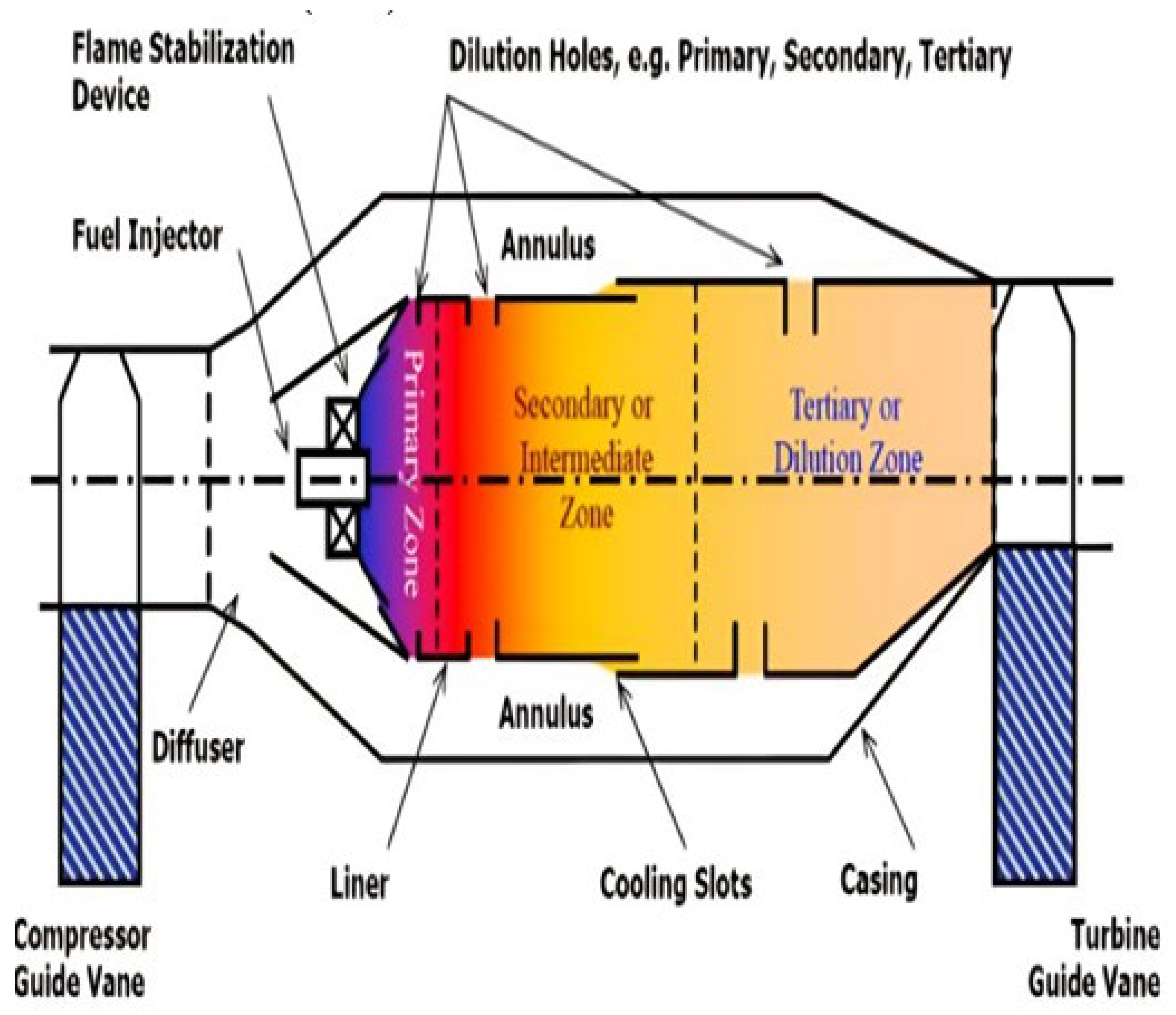
Figure 1.
Basic Designing of Combustion Chamber.
Figure 1.
Basic Designing of Combustion Chamber.
The flame (combustion) must be contained (kept) inside the combustor. If combustion occurs further back in the engine, the turbine stages are more likely to be overheated and damaged.
Furthermore, as turbine blades become more advanced and can endure greater temperatures, combustors are being constructed to burn at higher temperatures, and the parts of the combustor must be designed to resist those higher temperatures.
It should be able to relight at high altitude if the engine flames out.
Exit temperature profile that is consistent. If the exit flow contains hot patches, the turbine may be susceptible to thermal stress or other sorts of damage. Similarly, the temper- ature profile within the combustor should prevent hot patches, which can cause internal combustor damage or destruction.
Physical size and weight are both small. Because space and weight are at a premium in aero plane applications, a well-designed combustor attempts to be small. Non-aviation applications, such as power generation gas turbines, are not as hindered by this aspect.
Broad range of operation. Most combustors must be able to function with a wide range of inlet pressures, temperatures, and mass flows. These variables vary depending on engine settings and climatic conditions (for example, full throttle at low altitude can be considerably different from idle throttle at high altitude).
Process of Combustion in the Combustion Chamber
The air from the engine compressor reaches the combustion chamber at speeds of up to 500 feet per second, but because this is far too fast for combustion, the chamber must first disperse it, i.e., decelerate it and elevate its static pressure.
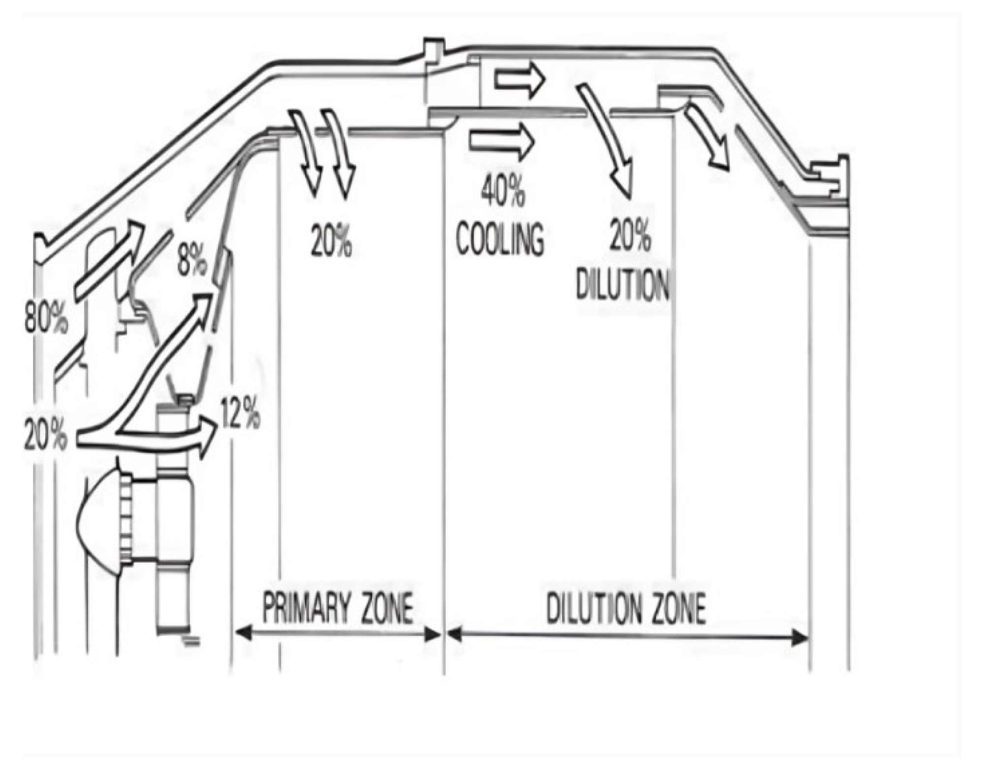
Figure 2.
Process of Combustion in the Combustion Chamber.
Figure 2.
Process of Combustion in the Combustion Chamber.
Because the speed of burning kerosene is only a few feet per second at standard mixture ratios, any fuel burnt even in the dispersed air stream, which now has a velocity of around 80 feet per second, would be blasted away. An area of low axial velocity must thus be produced in the chamber so that the flame remains lit throughout. The ratio of a combustion chamber can range between 45:1 and 130:1. Kerosene, on the other hand, will only burn efficiently at or near a ratio of 15:1, therefore the fuel must be burned with only a portion of the air entering the chamber, in what is known as a main combustion zone. This is accomplished by the use of a flame tube (combustion liner) with various systems for metering the air flow distribution throughout the chamber. The snout or entering segment absorbs approximately 20.
Path of Air Flow Distribution The Primary Air
This is the principal source of combustion air. It is heavily compressed air from a high-pressure compressor (typically decelerated via a Diffuser). That is sucked via the main channels in the combustor dome and the first set of liner holes. This air is combined with fuel and then burned.
The Air in the Middle
The air vaccinated into the combustion zone through the second set of liner holes is known as intermediate air (primary air goes through the first set). This air completes the response processes by cooling it and diluting the high levels of carbon monoxide (CO) and hydrogen (H2). Dilution air is airflow injected through holes in the combustion chamber liner to help cool the air before it reaches the turbine stages. The air is utilized carefully to achieve the desired uniform temperature profile in the combustor. But, when turbine blade technology advances, allowing blades to withstand greater temperatures, dilution air is required less, allowing more combustion air to be used.
The rotating air creates a flow upstream of the flame tube’s center, promoting the necessary re-circulation. The air that the snout does not pick up flows into the annular space between the flame tube and the air casing. A number of secondary holes in the wall of the flame tube body, next to the combustion zone, allow an additional 20 percent of the main flow of air to enter the primary zone. The air from the swirl vanes interacts with the air from the secondary air holes, resulting in a zone of low velocity re-circulation. This takes the appearance of a toroidal vortex, similar to a smoke ring, and serves to stabilize and anchor the flame (Fig.3). By swiftly bringing freshly injected fuel droplets to ignition temperature, the recirculating gases expedite their burning. It is set up so that the conical fuel spray from the nozzle intersects the re-circulation vortex in the center. Along with the normal turbulence in the main zone, this action substantially aids in breaking up the fuel and mixing it with the entering air. The temperature of the gases generated by combustion is around 1,800 to 2,000 degrees Celsius, which is far too hot for passage into the turbine’s nozzle guiding vanes. Cooling air can now enter a network of passageways within the flame tube wall before escaping to an insulating coating of air, according to a recent breakthrough. This can lower the amount of wall cooling airflow required by up to 50 percent. Otherwise, the incoming air will cool the flame and result in incomplete combustion if combustion is not completed before the diluting air enters the flame tube.
Relevant Contemporary Issue and Identification of Problem
Designing a combustion chamber that minimizes emissions of pollutants such as nitrogen oxides (NOx), carbon monoxide (CO), and particulate matter is a significant challenge. Striking a balance between combustion efficiency and low emissions re- quires careful design considerations. Continuous research and development efforts are dedicated to improving combustion chamber designs to enhance efficiency as well.
The aim of this research is to create a combustion chamber model for gas turbine engines that is affordable, easy to produce, and uses materials that are readily available. The goal is to design a chamber that not only cuts down on production time and costs but also maintains high efficiency and a good power-to-fuel ratio, making it a viable option for various uses in industries like aviation and power generation.
This study looks at different types of combustion chambers used in gas turbine engines, weighing their pros and cons to find the best option for this project. It focuses on selecting a design that balances cost, ease of fabrication, and performance. The paper outlines the entire process of building the chamber, including the materials used, the techniques applied, and the necessary safety and environmental considerations. It also suggests improvements and explores potential ways the new chamber model could be used in the future.
Background
Gas turbine engines have come a long way since their inception in the early 20th century. The idea began to take shape in the late 1930s when innovators like Sir Frank Whittle in the UK and Hans von Ohain in Germany created the first practical jet engines, primarily designed for aircraft. These early engines were revolutionary but faced issues with relia- bility and efficiency. As technology progressed—the improve- ments in materials, aerodynamics, and manufacturing—gas turbines became more efficient and capable of handling higher temperatures and pressures, which boosted their performance. By the mid-20th century, gas turbine technology began ex- panding into other fields, including power generation and marine applications. Key developments like advanced cooling techniques for turbine blades and the use of high-performance materials helped improve the efficiency and lifespan of these engines.
Today, gas turbine engines are widely used in various industries because of their high efficiency, reliability, and versatility. In aviation, they are the main power source for most commercial jets, military aircraft, and private planes, providing excellent performance for long-distance travel. In the energy sector, gas turbines are crucial for electricity generation, particularly in combined-cycle power plants, where they work alongside steam turbines to produce electricity more efficiently and with lower emissions compared to traditional coal-fired plants. This makes them vital in the shift toward cleaner energy sources. Gas turbines are also used in marine propulsion, powering large ships and naval vessels due to their ability to deliver high power in a compact design. Additionally, they play a role in industrial processes, such as oil and gas extraction, where they drive compressors and pumps, as well as in backup power systems and decentralized energy solutions.
The literature on gas turbine combustion chambers high- lights important advancements as well as ongoing challenges in the field. Bhimgade and Bhel [
1] emphasize the crucial role of computational fluid dynamics (CFD) in accurately modeling turbulence and mixing processes, which are essential for improving combustion efficiency. In line with this, Pawar and Bhalerao [
2] show through their simulations that higher exhaust temperatures in a can-type combustion chamber lead to better gas turbine efficiency. Kim and Kumaresh [
3] take this further by examining how different swirl angles affect emissions, finding that a 60° swirl angle significantly reduces NOx emissions due to improved cooling and mixing. Kumar and Rao [
4] focus on methane-fueled combustion chambers, revealing that increased turbulence intensity enhances combustion performance. Kalivarathan and Jeyalaxmi [
5] apply the RNG k- turbulence model to predict flow characteristics in combustors, suggesting that exploring a variety of turbulence models could lead to more accurate results. Ramazan, Jawaz Pasha, and Abdul Mujeeb M. S.[
6] demonstrate that a 10- degree swirl angle in an S-shaped duct improves pressure recovery and flow uniformity, especially with clockwise swirls. Meanwhile, Davidovic´, Kolarevic´, and Milosˇ [
7] discuss tubu- lar combustion chambers, highlighting their ease of production and the need for better fuel mixing to improve combustion stability.Schwing,Sattelmayer,and Noiray [
8] tackle the issue of thermoacoustic stability in premixed combustors, stressing the importance of experimental data to understand low-frequency oscillations. Bicsa´k, Hornya´k, and Veress [
9] explore how CAD systems can help reduce manufacturing costs while enhancing combustion chamber designs.Fagner, Rosa do Nascimento, and Rodrigues [
10] look into pressure losses within gas turbine combustion chambers, emphasizing
the importance of proper dimensioning for optimizing per- formance. Lefebvre and Norster [
11] provide insights into temperature distribution and mixing, advocating for designs that support efficient combustion.
Lastly, recent studies on can-annular combustors delve into their thermoacoustic properties [
12] and how rotational asymmetry affects instabilities [
13], further enriching the understanding of acoustic behavior in these systems. The main challenges identified in the literature are the accurate modeling of turbulence and mixing processes as highlighted by Bhimgade and Bhel [
1] and the resolution of thermoacoustic instabilities as discussed by Schwing, Sattelmayer and Noiray [
8]. Furthermore, achieving low NOx emissions while main- taining high combustion efficiency remains a major obstacle in combustion chamber design, as investigated by Kim and Kumaresh [
3] .
The advancement of CFD technology, such as Kalivarathan and Jeyalaxmi [
5] discussions, provides promising ways to better predict and analyze the liquidity of liquidity in the burning room. As BISa´k, Hornya´k and Verses [
9] pointed out, the integration of CAD tools to optimize design is a key trend in reducing costs and improving performance. Future research will likely focus on refining these computational models, exploring new cooling strategies, and developing more efficient low-emission combustion systems.
A major gap in the current research is the limited exper- imental validation of CFD models, especially in connection with thermoacoustic behavior and mixing efficiency. As high- lighted by Schwing, Sattelmayer and Noiray [
8], more exper- imental data is needed to validate the calculation predictions. Additionally, Davidovic´, Kolarevic´, and Milosˇ [
7] point out the need for further research into improving fuel mixing efficiency in tubular combustion chambers.
The literary study illustrates the progress of the design and analysis of the burning premises in a gas turbine, especially in terms of improving combustion efficiency and reducing emis- sions. There are still many tasks for turbulence, warm sound instability and continuous problems with more experimental testing. Emerging computational techniques and design tools hold promise for addressing these challenges, paving the way for more efficient and environmentally friendly gas turbine technologies.
I. Design Flow/Process
The can-type combustion chamber is chosen based on the literature study for its simplicity, durability and high combus- tion efficiency. It offers safe operation, low pressure loss and withstands high temperature and pressure, ensuring complete combustion.
A. Equations
The chamber volume is typically determined based on the desired thrust or power output and the specific impulse or efficiency of the engine.
V = (Thrust or Power) / (Pressure × Specific Impulse) Chamber Length.
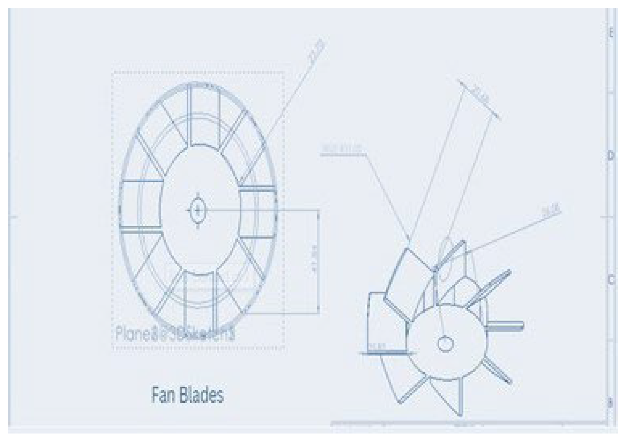
Figure 3.
2-D Design of Blades.
Figure 3.
2-D Design of Blades.
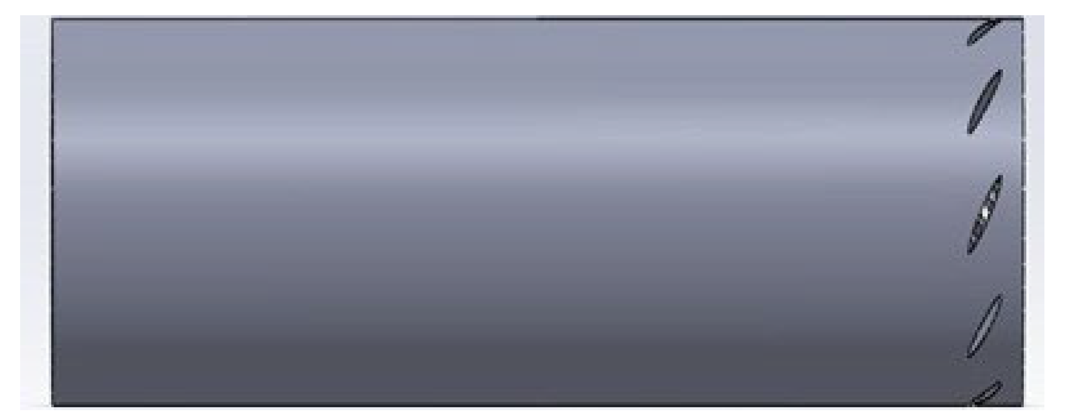
Figure 4.
Swirler inside chamber side view.
Figure 4.
Swirler inside chamber side view.
The chamber length is typically determined based on the desired residence time of the combustion gases.
L = Residence Time × Average Combustion Gas Velocity Chamber Diameter:
Diameter is determined by using a throat area based on the desired mass flow rate and combustion chamber pressure.
D = Throat Area = (Mass Flow Rate) / (Chamber Pressure) Chamber Diameter = (4 × Throat Area / π)
Swirler Area:
Swirler Area = Π((swirler diameter)/2)2 Adjusted Swirler Area = Swirler Area × η Efficiency Factor - (η)
The efficiency factor typically ranges from 0 to 1 Nozzle Area:
Nozzle Area = (Mass Flow Rate) / (Exit Velocity × Chamber Pressure)
I. Simulations Setup
The approach we are using for this problem is Finite Element Method (FEM) which is a popular method for nu merically solving differential equations arising in engineering and mathematical modeling, for which we are mainly focusing on the swirler analysis of the combustion chamber. And find its effects in primary secondary zone of combustion chamber. The effective swirler leads to more complete combustion and have a significant reduction in emissions. The detailed materials properties of combustor are tabulated and illustrated in
Table 1..
I. Results
The simulations results of swirler have been illustrated.
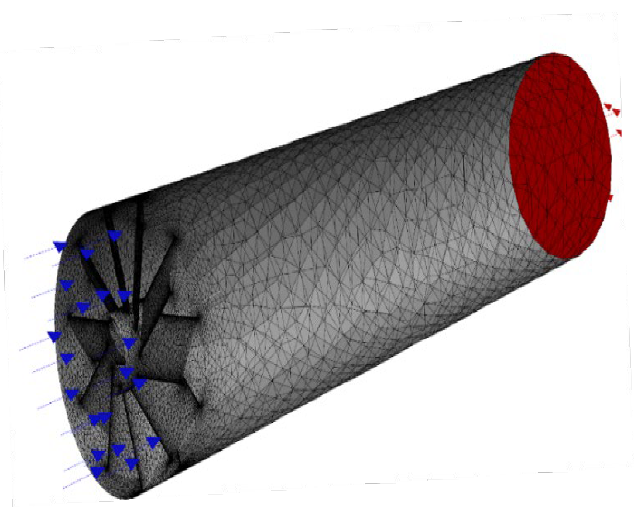
A. Meshing of Swirlers
There are 29,783 nodes, 16,577 elements, 4,818 corner nodes, 24,965 mid nodes, and 16,577 solid elements in the mesh model. These components are utilized in the simulation to discretize the computational domain and represent the physical world. There are additionally 4,818 corner nodes, 24,965 mid nodes, and 16,577 solid components in the mesh model. With this degree of mesh resolution and complexity, simulation results may be thorough and precise for analyzing the flow and thermal behavior within the can-type combustion chamber.
Figure 6.
Meshing of swirlers.
Figure 6.
Meshing of swirlers.
The results for pressure, temperature, Turbulent Viscosity, Emission of CO and velocity contour have been illustrated.
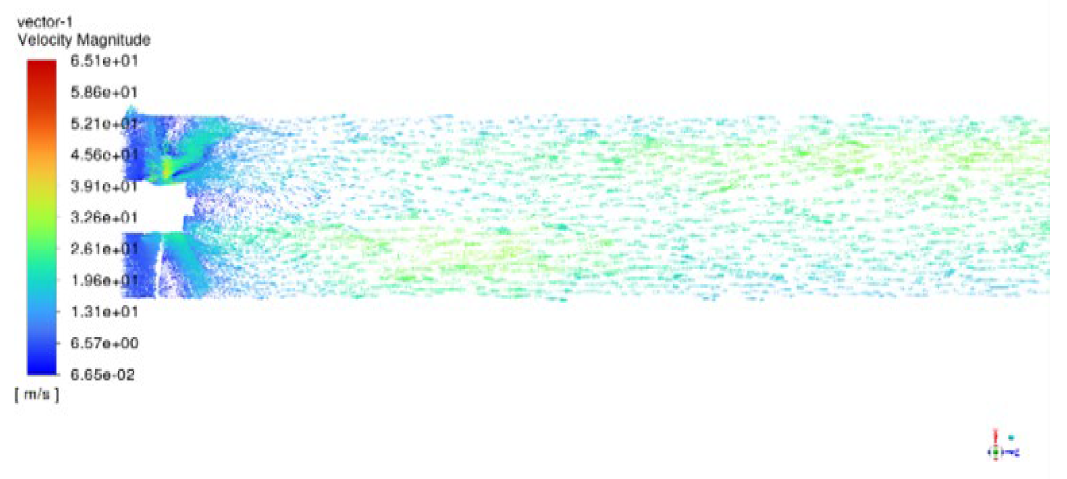
A. Velocity Magnitude
The range of the velocity magnitude lies from 6.65e-02 to
6.51e+01. But the average velocity if found to be followed everywhere i.e., at the intake of the swirler the velocity is
6.57e+00 and decreases further till 3.26e+01. We found there are various points where air-fuel mixture starts to deflect from the path mostly at the outer edges due to the decrease in velocity.
Figure 5.
velocity magnitude.
Figure 5.
velocity magnitude.
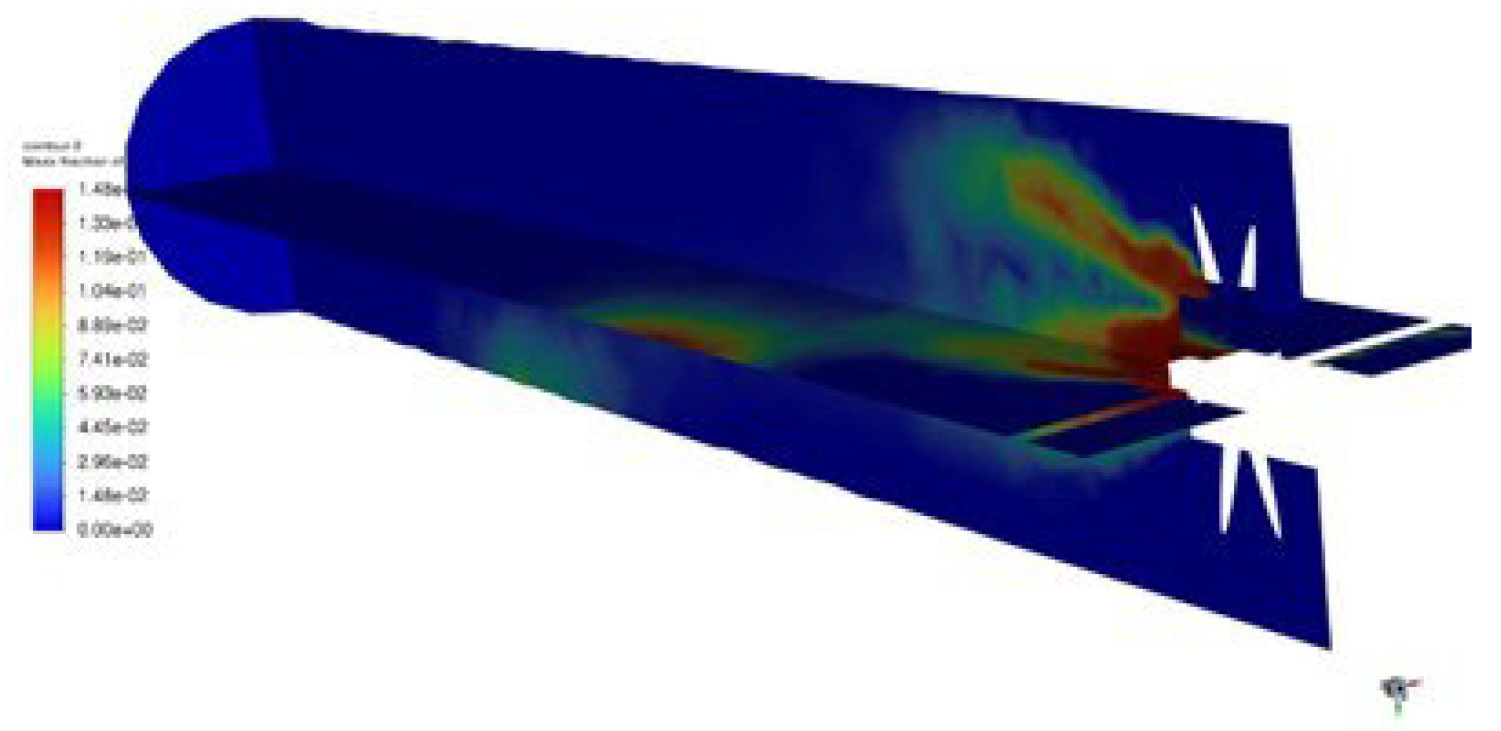
A. Emission of CO
The Figures shows the Mass fraction of Co con- tour 2 lies from 0.00e+00 to 1.48e-11. The mass fraction of CO is continuously decreased due to the combustion inside the combustion chamber. The blue colored line depicts the CO that come from air inlet wit air. The concentration of CO is decreased due to large amount of heat is produced inside the combustion chamber.
Figure 7.
Mass fraction of CO / Emission of CO.
Figure 7.
Mass fraction of CO / Emission of CO.
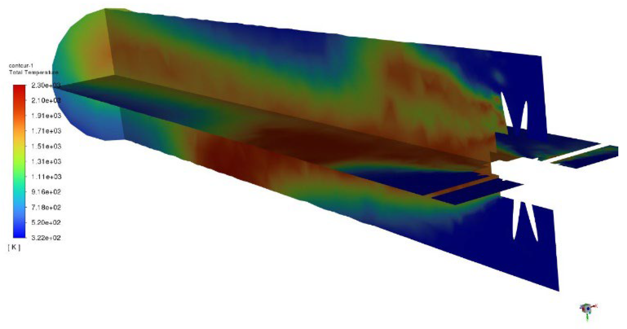
A. Temperature Distribution
The figure explains about the Temperature variation inside the Can Type combustion chamber of gas turbine engine which ranges from 3.22e+02 to 2.30e+03. The blue colored indicates the air and the red color indicates the reaction of fuel with air inside the combustion chamber. The reaction of fuel with air produces large amount of heat inside the combustion chamber.
Figure 8.
Temperature Distribution.
Figure 8.
Temperature Distribution.
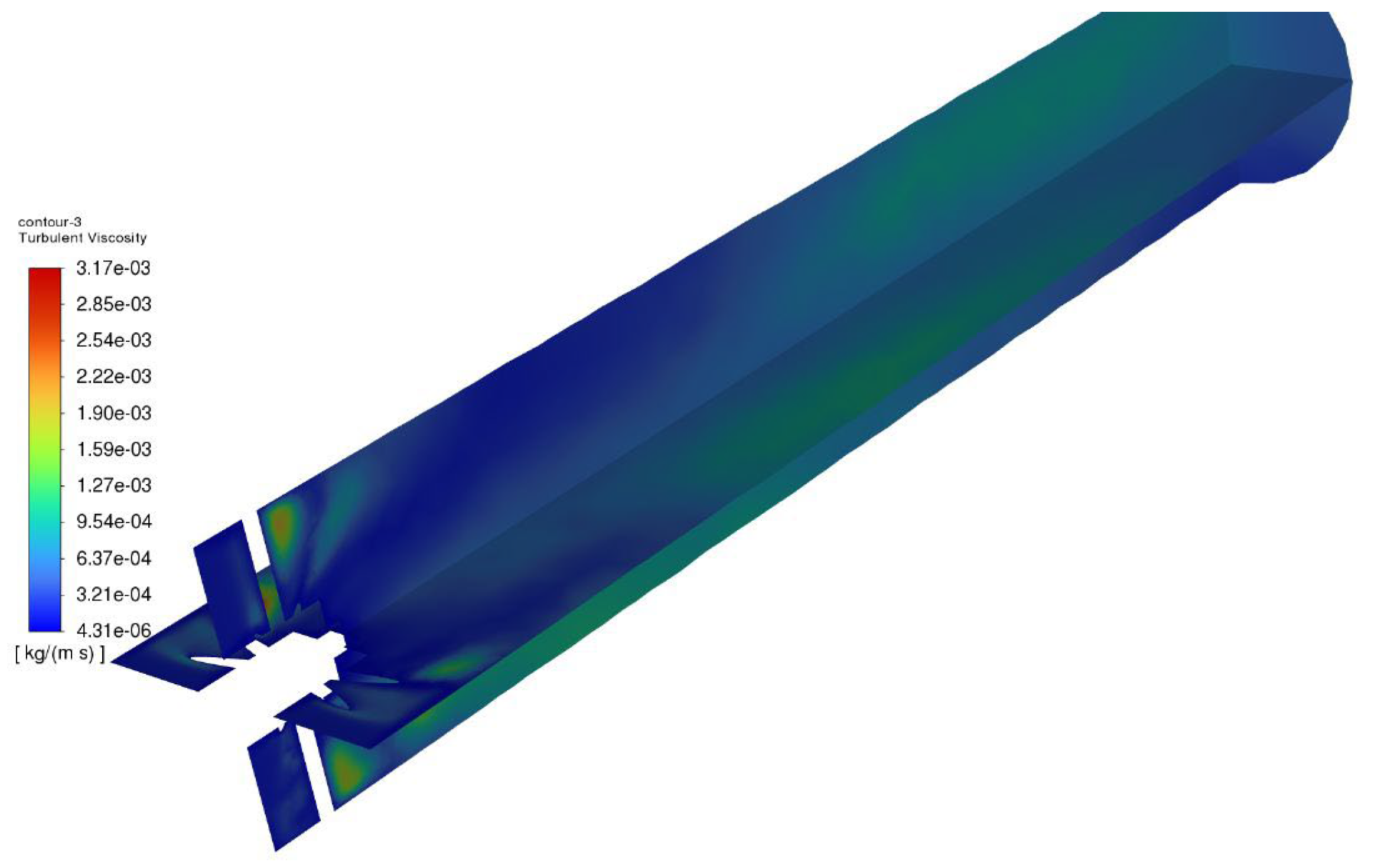
A. Turbulent Viscosity
According to the simulation results, the turbulent viscosity of the can-type combustion chamber ranges from 4.31e-06 to 3.17e-03 kg/ms. Turbulent viscosity is the measure of a fluid's resistance to flow induced by turbulence. It depicts the viscosity of the turbulent flow within the combustion chamber in this scenario. Turbulent flows have chaotic and uneven motion, and turbulent viscosity measures the strength of this turbulence. The simulation's range of results reveals that the degree of turbulence within the combustion chamber can vary dramatically. A lower turbulent viscosity of 4.31e-06 kg/ms indicates a smoother, less chaotic flow with less resistance to motion. A higher number of 3.17e-03 kg/ms, on the other hand, suggests a more turbulent and chaotic flow with greater resistance to motion. Understanding and analysing turbulent viscosity in a combustion chamber is critical for optimising combustion processes, guaranteeing effective fuel-air mixing, and meeting performance objectives. These simulation findings may be used to fine-tune the combustion chamber's design and operating parameters for higher combustion efficiency and lower emissions.
Figure 9.
Turbulent Viscosity.
Figure 9.
Turbulent Viscosity.
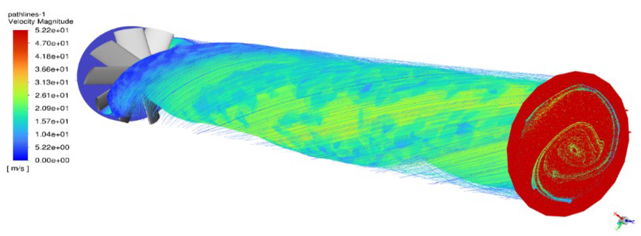
A. Velocity Magnitude of Path Lines
The velocity magnitude of pathlines in a can-type combustion chamber as simulated ranges from 0.00e-00 to 5.22e+01 m/s. The magnitude of the velocity indicates the speed of the fluid flow within the chamber. The measured data show a wide range of flow velocities, with some regions having very low or insignificant speeds near to 0 m/s and others experiencing comparatively higher velocities surpassing 52.2 m/s. These findings shed light on the flow dynamics within the combustion chamber and may be used to assess the combustion process's performance and efficiency.
Figure 10.
Velocity Magnitude of Path lines.
Figure 10.
Velocity Magnitude of Path lines.
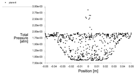
A. Total Pressure Vs Position
Graph 1:Total Pressure Vs Position.
The total pressure versus position plot in a can-type combustion chamber displays the pressure distribution across the chamber at various points. Total pressure is the total of static and dynamic pressures, and it represents the fluid's energy content.
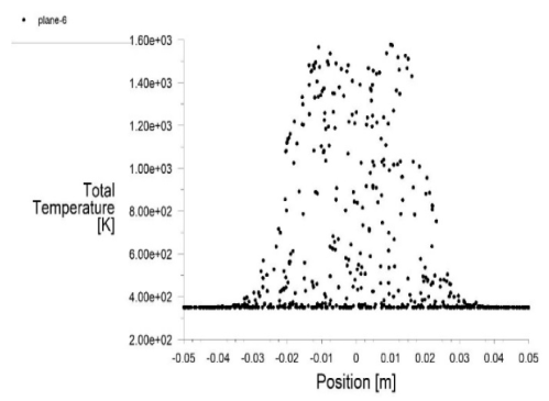
A. Total Temperature Vs Position
The total temperature versus position in a can-type combustion chamber displays the temperature distribution across the chamber at various places. The combination of static temperature and kinetic energy associated with fluid movement is referred to as total temperature. Temperature gradients, regions of high or low temperature, and possible locations of heat transfer or combustion inefficiencies can all be shown by the figure. It reveals information on fuel and air mixing and combustion, heat release patterns, and the thermal interaction of gases and combustion products within the chamber.
Graph 2: Total Temperature Vs Position.
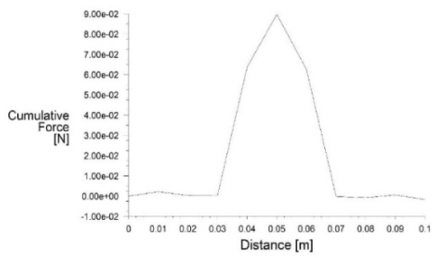
A. Cumulative Force Vs Distance
Graph 3: Cumulative Force Vs Distance.
In a can-type combustion chamber, the cumulative force against distance is the overall force applied on a body or object within the chamber as a function of distance from a reference point. This data can give valuable insights into the mechanical behaviour of the chamber, such as areas of high or low force concentration, possible stress or strain regions, and structural integrity concerns. The cumulative force distribution analysis may help optimise the design and material selection for the combustion chamber, ensuring that components can sustain the forces applied on them without failure or excessive deformation.