Submitted:
12 February 2025
Posted:
13 February 2025
You are already at the latest version
Abstract
Optimizing the design of the exhaust manifold plays a crucial role in enhancing engine efficiency, reducing fuel consumption, and minimizing pollutant emissions in internal combustion engines. This study aims to improve the exhaust manifold geometry of the M3 engine, manufactured by PIDOCO (Pioneer Intelligence Design Origin Co.). The primary design objectives include reducing pressure drop and enhancing flow uniformity across the surface of the monolithic catalyst. To achieve these goals, a modified exhaust manifold geometry for the M3 engine was designed, and Computational Fluid Dynamics (CFD) simulations were conducted to evaluate the proposed designs. The geometries were created using CATIA software, while ANSYS Fluent was employed for CFD analysis. The results indicate that optimizing the exhaust manifold geometry reduces pressure drop by 45%, improves the flow uniformity index by 36%, and leads to a minimum 4.5% reduction in vehicle gaseous emissions.
Keywords:
Exhaust manifold
; CFD
; Pressure drops
; Pollutant emissions
; PIDOCO
1. Introduction
The study of three-dimensional flow behavior in internal combustion engines has always been a crucial topic for engine designers. The exhaust manifold, acting as the engine’s respiratory system, plays a fundamental role in achieving optimal engine performance. A well-designed exhaust manifold can enhance engine efficiency, power, and torque while reducing fuel consumption and emissions. Improving the design of exhaust passages is essential for facilitating the efficient expulsion of exhaust gases from the combustion chamber without causing unwanted backpressure.
One of the major challenges in exhaust manifold design is gas accumulation at the outlet, which reduces the available space for gas evacuation. Increasing the pressure, velocity, and temperature of the exhaust gases from each cylinder can improve air intake and fuel mixture in the combustion chamber, ultimately enhancing engine power and efficiency. Contrary to the common belief that increasing the diameter of exhaust pipes improves performance, the key factor in proper gas evacuation is fluid velocity. The exhaust system designer must understand the importance of balancing flow capacity and fluid velocity, as higher exhaust pulse velocity results in better gas expulsion [1,2,3].
Numerous studies have been conducted on the behavior of exhaust manifolds in internal combustion engines using numerical and experimental methods. Jatoth et al. [4] used the fourth-order Runge-Kutta method to solve differential equations in the exhaust manifold. Aziz et al. [5] analyzed the impact of exhaust manifold parameters on engine performance using a linear wave model. Davari et al. [6,7] studied exhaust manifold to reduce emissions. Liu et al. [8] investigated energy retention from exhaust gases and the reduction of pressure pulse interference in turbocharged diesel engines. Bao et al. [9] conducted numerical analysis using ANSYS software on various exhaust manifold designs. Davari et al. [10] evaluated eight different exhaust manifold designs to reduce emissions and enhance combustion efficiency. jemni et al. [11] used computational fluid dynamics analysis to optimize different designs for reducing backpressure and improving engine volumetric efficiency. Bianco et al. [12] using CFD simulations based on the k-ε model, reported a 26% reduction in flow losses compared to the initial model. Talati et al. [13] examined two different exhaust manifold designs in a four-cylinder gasoline engine and demonstrated that exhaust flow sensitivity varies with crankshaft angle. Bajpai et al. [14] evaluated the efficiency of exhaust manifolds for three different fuel types in a four-cylinder gasoline engine. Harari et al. [15] studied the exhaust manifold flow characteristics of a spark-ignition engine using various fuels. Chian et al. [16] examined the impact of exhaust manifold design on engine performance and efficiency. Murali et al. [17] reviewed the relationship between exhaust backpressure and internal combustion engine performance through a literature survey. Izzat et al. [18] demonstrated that exhaust manifold parameters, including material type and geometric dimensions, significantly affect engine performance and efficiency, and that certain geometric modifications can reduce backpressure. Sangamesh et al. [19] compared dual and single exhaust manifold designs, concluding that the dual manifold provides better stress and temperature distribution while experiencing lower mechanical stress. Bober et al. [20] analyzed the effects of different exhaust manifold designs on power and torque curves.
Given the extensive research conducted, it is evident that the design and flow simulation of exhaust manifolds are crucial aspects of engine development. This study focuses on optimizing the exhaust manifold geometry of the M3 engine. The primary objective of this research is to minimize pressure loss and improve velocity distribution as key design parameters. The selected geometry was designed and analyzed using ANSYS and CATIA software to identify the configuration with the lowest pressure loss and the most uniform velocity distribution at the exhaust manifold outlet. Modifying the geometry and angles of the intake pipes is expected to significantly enhance flow performance in both upstream and downstream sections, ultimately reducing pressure loss and optimizing gas velocity distribution for improved engine performance.
2. Methodology
Evaluating exhaust manifold geometries through physical experiments using trial-and-error methods can be costly and time-consuming. To overcome these limitations, computational fluid dynamics simulations offer a more efficient and cost-effective alternative, allowing for a detailed examination of flow characteristics, pressure distribution, and velocity profiles. When combined with experimental testing, this approach enables researchers to conduct a comprehensive evaluation of different geometries, leading to improved design optimization.
In this study, the exhaust manifold of the M3 engine, developed by PIDOCO (Pioneering Intelligent Design Origin Co.), was selected as the basis for simulation. The initial exhaust manifold geometry was first designed using CATIA software. Mesh generation, essential for accurately representing flow behavior, was performed using ANSYS software. Subsequently, the simulated flow behavior within the exhaust manifold was analyzed by solving the Navier-Stokes equations governing the motion of viscous fluids [21,22]. This method provided crucial insights into flow patterns within the M3 engine’s exhaust manifold, aiding in design improvements. Figure 1 illustrates the 3D model of the modified exhaust manifold geometry for the M3 engine.
In the initial mesh generation, the element size was set to 3 mm, selected based on the geometry of the exhaust manifold (Figure 2). This choice aimed to balance accuracy and computational speed in numerical simulations, considering factors such as geometric complexity, the required level of detail, and data processing capacity.
In the modeling of the exhaust manifold geometry, several assumptions were considered: the flow was assumed to be incompressible, turbulent, and steady-state. A pressure-based numerical solution method was used. The energy equation was deactivated since thermal analysis was not the focus of this study. Cast iron, with a density of 7,150 kg/m³, was selected as the material for the walls. Fluid properties were set to the default air values in the software. The inlet velocity was set to 10 m/s, based on the M3 engine specifications, with a turbulence intensity of 10% in all simulations.
Due to the lack of available data on outlet velocity, the outlet boundary conditions were defined based on atmospheric pressure (101,325 Pa) at a specified distance, as shown in Figure 3. The hydraulic diameter of the M3 engine’s exhaust manifold was calculated as 31 mm based on the inlet diameters and 101 mm based on the manifold’s outlet diameter.
Selecting an appropriate turbulence model is essential for accurately estimating flow characteristics within the exhaust system, as turbulent flow significantly impacts the results. A review of the advantages and disadvantages of the k-ε turbulence model has led to improvements aimed at enhancing its efficiency. This model is particularly suitable for confined flows where shear stresses are dominant. Compared to the standard k-ε model, the RNG k-ε model offers better accuracy in simulating turbulent flow effects in geometrically curved systems like exhaust manifolds [23,24,25,26]. Therefore, the RNG k-ε turbulence model was chosen for this study.
To ensure the accuracy of the numerical solution, results must be independent of the number of mesh cells. However, increasing the number of mesh divisions leads to more complex computations, impacting processing time and memory requirements. Thus, achieving a balance between mesh density and available computational resources is essential. It is noteworthy that the results were computed at the High-Performance Computing Center of PIDOCO.
To ensure the reliability of the numerical solution, mesh independence studies were conducted to assess convergence by comparing results from different mesh sizes and evaluating their consistency and stability [27,28].
Figure 4 illustrates the mass flow rate at the exhaust manifold outlet for different mesh configurations. The minor variations in mass flow rate between the two finest meshes indicate that the results have become independent of the number of cells. The total number of mesh elements for the exhaust manifold geometry was determined to be 1,795,000.
3. Results and Discussion
The pressure contours illustrate the pressure drop from the inlet to the outlet in the manifold geometry, which is a necessary condition for achieving the desired flow direction. This result is shown in Figure 5. The bends in the exhaust manifold geometry cause pressure variations. As the flow passes through a bend, it experiences a radial pressure gradient due to centrifugal forces, pushing the fluid outward before it returns inward along the wall.
Reverse pressure gradients near the inner and outer walls of the bends can lead to flow separation and increased pressure losses. The pressure drops in bends results from friction and momentum exchange due to flow direction changes. Factors such as bend angle, curvature ratio, and Reynolds number influence the extent of pressure loss. Understanding flow behavior in bends is essential for optimizing performance and minimizing pressure losses.
Table 1 presents the pressure drop values for each geometry, along with the total pressure difference between the inlet and outlets. Comparing the percentage of pressure loss allows for evaluating the efficiency of each design in minimizing pressure drop, aiding in the optimization of the exhaust manifold geometry to enhance engine performance.
The optimized geometry demonstrated the best performance in reducing pressure loss throughout the exhaust manifold, achieving a 45% reduction compared to the initial design. The results indicate that this geometry effectively reduces pressure drop, improves flow quality, and decreases resistance, leading to an overall enhancement in manifold performance. According to studies by Zare et al. [22], 45% reduction in average pressure drop within the exhaust manifold can increase engine torque by approximately 11%, contributing to improved performance and reduced fuel consumption.
In the simulations, the inlet effect was considered, and due to the length of the exhaust manifold, the outlet flow was not fully developed. Figure 6 presents the velocity magnitude contour at the exhaust manifold outlet, allowing for an assessment of flow uniformity at the exit.
Improving flow uniformity at the catalyst inlet enhances its performance and reduces emissions. Table 2 summarizes the standard deviation and flow uniformity index at the exhaust manifold outlet. Simulation results indicate a significant improvement in flow uniformity at the manifold outlet compared to the initial design.
Considering the empirical equations provided on the impact of exhaust gas flow uniformity on catalyst performance and pollutant conversion rates during the ECE + EUDC cycle test, the effect of flow uniformity on geometry was analyzed. The pollutant conversion rates are reported in Table 3. With modifications to the exhaust manifold geometry, it was observed that increased flow uniformity improved the conversion rates of NOx, HC, and CO pollutants by an average of up to 4.5%. Changes in the geometry and angles of the inlet pipes significantly enhanced performance in both upstream and downstream sections, leading to improved flow characteristics, reduced pressure drop, and a more balanced distribution of gas velocities, ultimately resulting in enhanced engine performance.
4. Conclusion
In this study, the impact of exhaust manifold geometry on the performance of the M3 engine was investigated through the design and analysis of an optimized geometry using CFD. Simulation results indicated that pressure decreased along the exhaust manifold, and the examined geometry exhibited the lowest pressure drop, with a reduction to only 45% of the pressure drop observed in the initial design. This decrease in pressure drop led to an 11% increase in engine torque. The 11% increase in torque contributed to improved engine performance, reduced fuel consumption, and ultimately, lower emissions.
The analysis of velocity uniformity in the exhaust manifold outlet contours, along with the evaluation of the standard deviation and flow uniformity index, demonstrated a significant improvement in flow uniformity at the exhaust manifold outlet. The flow uniformity index in this geometry increased by 36%, indicating that geometric modifications resulted in a more uniform flow distribution, which is highly beneficial for the performance of the three-way catalyst. The results suggest that this geometry represents the optimal exhaust manifold design for the M3 engine due to its reduced pressure drop and improved flow uniformity. Shortening the manifold inlet length, increasing the collector length, and adjusting the angles in this geometry all contributed to its superior performance. These findings provide valuable insights for the design and development of future exhaust manifolds focused on enhancing engine efficiency.
References
- Saboohi, Z.; Moradi, A.; Hosseini, S.E.; Karimi, N. Experimental investigation of atmospheric boundary layer using unmanned aerial system equipped with novel measurement system. Meteorol. Atmospheric Phys. 2025, 137, 1–17. [Google Scholar] [CrossRef]
- Z. Saboohi, S.E. Hosseini, Advancements in Biogas Production: Process Optimization and Innovative Plant Operations, Clean Energy (2025). [CrossRef]
- Hosseini, S.E.; Jafaripanah, S.; Saboohi, Z. CFD simulation and aerodynamic optimization of two-stage axial high-pressure turbine blades. J. Braz. Soc. Mech. Sci. Eng. 2024, 46, 1–20. [Google Scholar] [CrossRef]
- Jatoth, R.; Gugulothu, S.K.; Gadepalli, R.K.S.; Burra, B.; Rafiuzzama, S. Impact of thermophoresis factor on soot particle trajectories near the in-cylinder wall in a diesel engine. Int. J. Environ. Sci. Technol. 2021, 19, 897–912. [Google Scholar] [CrossRef]
- A Aziz, N.; A Rahman, M.T.; Amin, N.A.M.; Bin Mohamad, M.S.; Mohamad, A.; Izham, M.; Saad, M.A.M. Flow characterisation in an exhaust manifold of a single-cylinder internal combustion engine (ICE). J. Physics: Conf. Ser. 2021, 2129. [Google Scholar] [CrossRef]
- Davari, S.; Ommi, F.; Saboohi, Z.; Safar, M. Experimental Study of the Effect of a Non-Oxygenated Additive on Spark-Ignition Engine Performance and Pollutant Emissions. Int. J. Eng. 2021, 34, 1035–1045. [Google Scholar] [CrossRef]
- Davari, S.; Ommi, F.; Saboohi, Z. Investigating the Effects of Adding Butene, Homopolymer to Gasoline on Engine Performance Parameters and Pollutant Emissions: Empirical Study and Process Optimization. J. Inst. Eng. (India): Ser. C 2022, 103, 421–434. [Google Scholar] [CrossRef]
- Liu, S.; Zhuge, W.; Zhang, Y. Numerical and experimental investigation of exhaust manifold configurations of turbo-charged diesel engines. Proc. Inst. Mech. Eng. Part A: J. Power Energy 2020, 235, 1119–1130. [Google Scholar] [CrossRef]
- Bao, J.-B.; Zhang, K. An Analysis on the Thermal Flow Characteristics of the Car Exhaust Manifold Geometry. J. Physics: Conf. Ser. 2023, 2610, 012018. [Google Scholar] [CrossRef]
- S. Davari, F. Ommi, Z. saboohi, Experimental study of the effects of adding methylated homopolymer to gasoline on the engine performance and pollutant emissions, J. Solid Fluid Mech. 11 (2021) 199–210. [CrossRef]
- Jemni, M.A.; HadjKacem, S.; Ammar, M.; Saaidia, R.; Brayek, M.; Abid, M.S. Variable intake manifold geometry influence on volumetric efficiency enhancement at gaseous engine starting speeds. Proc. Inst. Mech. Eng. Part E: J. Process. Mech. Eng. 2020, 235, 548–559. [Google Scholar] [CrossRef]
- Bianco, V.; Szubel, M.; Matras, B.; Filipowicz, M.; Papis, K.; Podlasek, S. CFD analysis and design optimization of an air manifold for a biomass boiler. Renew. Energy 2020, 163, 2018–2028. [Google Scholar] [CrossRef]
- Talati, H.; Aliakbari, K.; Ebrahimi-Moghadam, A.; Farokhad, H.K.; Nasrabad, A.E. Optimal design and analysis of a novel variable-length intake manifold on a four-cylinder gasoline engine. Appl. Therm. Eng. 2021, 200, 117631. [Google Scholar] [CrossRef]
- Bajpai, K.; Chandrakar, A.; Agrawal, A.; Shekhar, S. CFD Analysis of Exhaust Manifold of SI Engine and Comparison of Back Pressure using Alternative Fuels. IOSR J. Mech. Civ. Eng. 2017, 14, 23–29. [Google Scholar] [CrossRef]
- Harari, P.A.; Banapurmath, N.R.; Yaliwal, V.S.; Khan, T.M.Y.; Badruddin, I.A.; Kamangar, S.; Mahlia, T.M.I. Effect of Injection Timing and Injection Duration of Manifold Injected Fuels in Reactivity Controlled Compression Ignition Engine Operated with Renewable Fuels. Energies 2021, 14, 4621. [Google Scholar] [CrossRef]
- Ci̇han, Ö.; Bulut, M. CFD Analysis of Exhaust Manifold for Different Designs. Eur. Mech. Sci. 2019, 3, 147–152. [Google Scholar] [CrossRef]
- Murali, R.; Shahriman, A.B.; Razlan, Z.M.; Ahmad, W.K.W.; I Azizul, A.; A Rojan, M.; Ma’arof, M.I.N.; A Radzuan, M.; Hassan, M.A.S.M.; Ibrahim, Z. A review on the correlation between exhaust backpressure and the performance of IC engine. J. Physics: Conf. Ser. 2021, 2051, 012044. [Google Scholar] [CrossRef]
- M. Izzat, N. Ma, A.A. Rana, L.K. Hen, J. Raman, Exhaust Manifold Assessment for Backpressure Minimization, 2023 (2023) 2019–2024.
- Sangamesh, R.; Twinkle, R.; Chiniwar, D.S.; Vishwanatha, H.M.; Sondar, P.; Hiremath, S. Modelling of single and multi-port manifolds and studying the influence of structural and thermal behaviour on exhaust manifolds used in automotive applications. Int. J. Interact. Des. Manuf. (IJIDeM) 2022, 18, 2237–2246. [Google Scholar] [CrossRef]
- Bober, B.; Andrych-Zalewska, M.; Boguś, P. Influence of exhaust manifold modification on engine power. Combust. Engines 2023, 196, 54–65. [Google Scholar] [CrossRef]
- Hosseini, S.E.; Keshmiri, A. Experimental and numerical investigation of different geometrical parameters in a centrifugal blood pump. Res. Biomed. Eng. 2022, 38, 423–437. [Google Scholar] [CrossRef]
- Zare, J.; Zare, J.; Hosseini, S.E.; Hosseini, S.E.; Rastan, M.R.; Rastan, M.R. Airborne dust-induced performance degradation in NREL phase VI wind turbine: a numerical study. Int. J. Green Energy 2023, 21, 1295–1314. [Google Scholar] [CrossRef]
- Hosseini, S.E.; Deyranlou, A.; Talebizadehsardari, P.; Mohammed, H.I.; Keshmiri, A. Developing a numerical framework to study the cavitation and non-cavitation behaviour of a centrifugal pump inducer. Int. J. Nav. Arch. Ocean Eng. 2024, 16. [Google Scholar] [CrossRef]
- Hosseini, S.E.; Saboohi, Z. Ducted wind turbines: A review and assessment of different design models. Wind. Eng. 2024. [Google Scholar] [CrossRef]
- Shojaeefard, M.H.; Hosseini, S.E.; Zare, J. CFD simulation and Pareto-based multi-objective shape optimization of the centrifugal pump inducer applying GMDH neural network, modified NSGA-II, and TOPSIS. Struct. Multidiscip. Optim. 2019, 60, 1509–1525. [Google Scholar] [CrossRef]
- M.H. Shojaeefard, S.E. Hosseini, J. Zare, Numerical simulation and multi-objective optimization of the centrifugal pump inducer, Modares Mech. Eng. 17 (2018) 205–216.
- Hosseini, S.E.; Salehi, F. Analyzing overlap ratio effect on performance of a modified Savonius wind turbine. Phys. Fluids 2023, 35. [Google Scholar] [CrossRef]
- Hosseini, S.E.; Karimi, O.; AsemanBakhsh, M.A. Experimental investigation and multi-objective optimization of savonius wind turbine based on modified non-dominated sorting genetic algorithm-II. Wind. Eng. 2023, 48, 446–467. [Google Scholar] [CrossRef]
Figure 1.
3D model designed for the modified geometry of the M3 engine exhaust manifold.
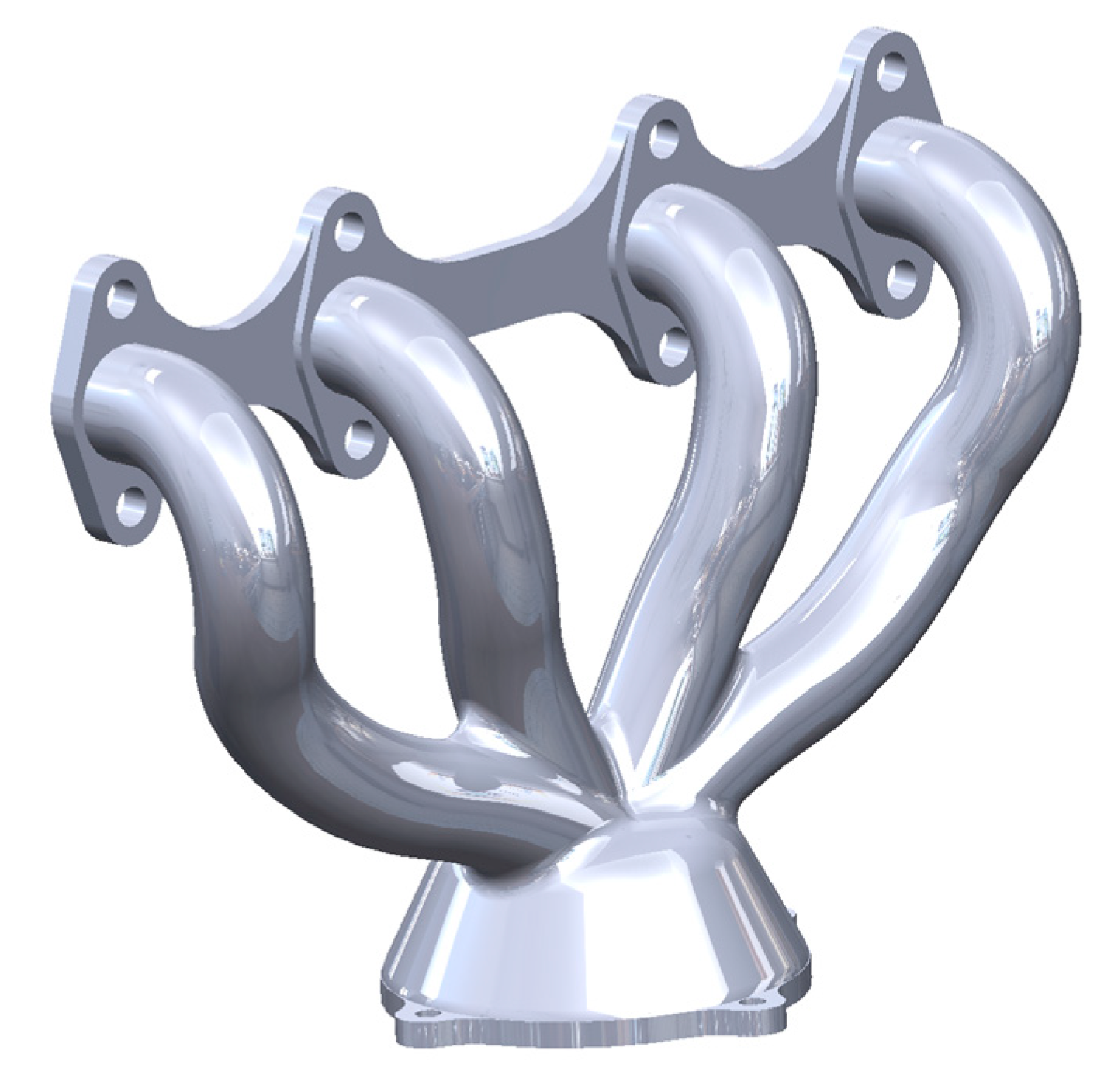
Figure 2.
Initial mesh created for the exhaust manifold.
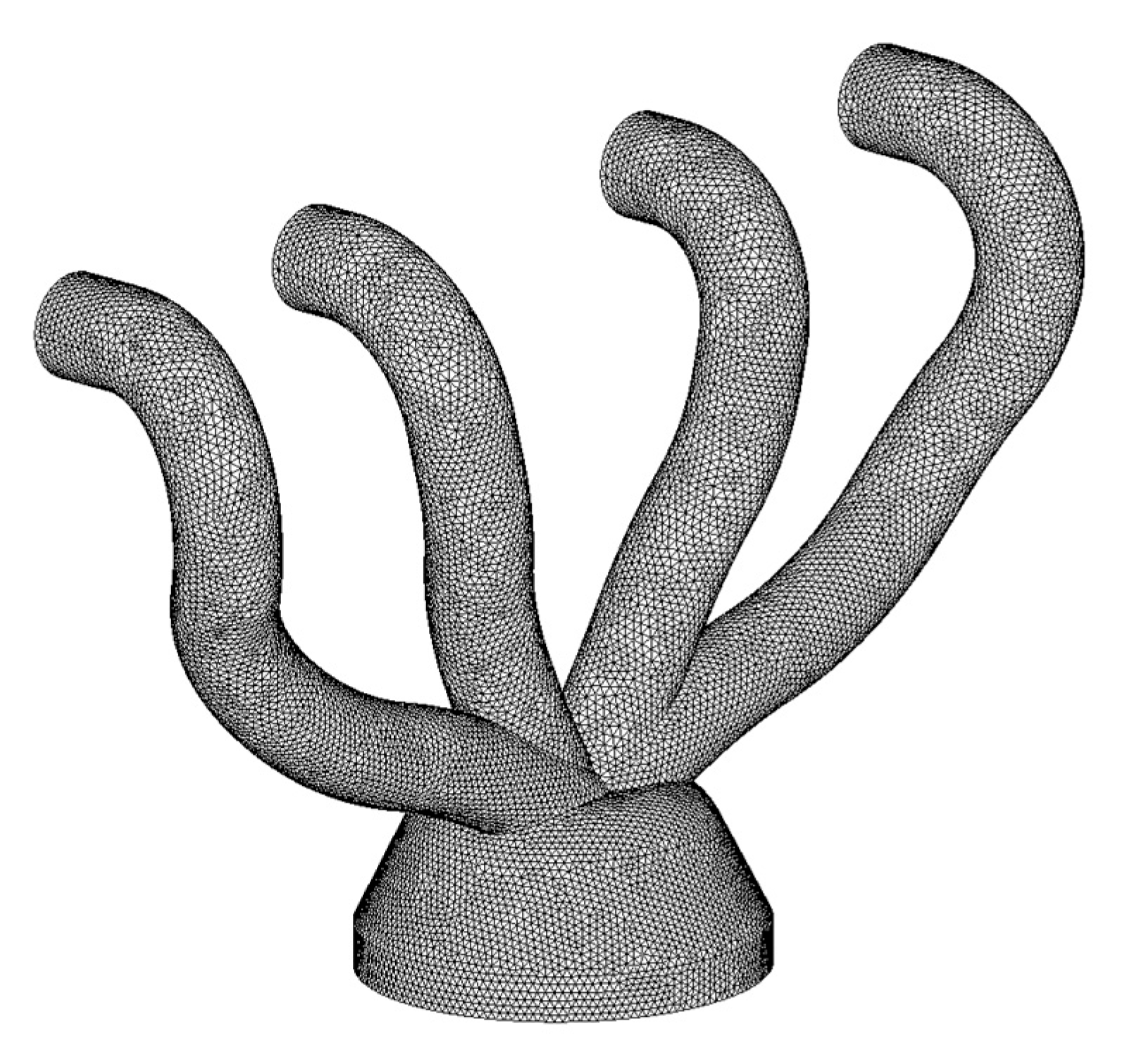
Figure 3.
Boundary conditions for the exhaust manifold.
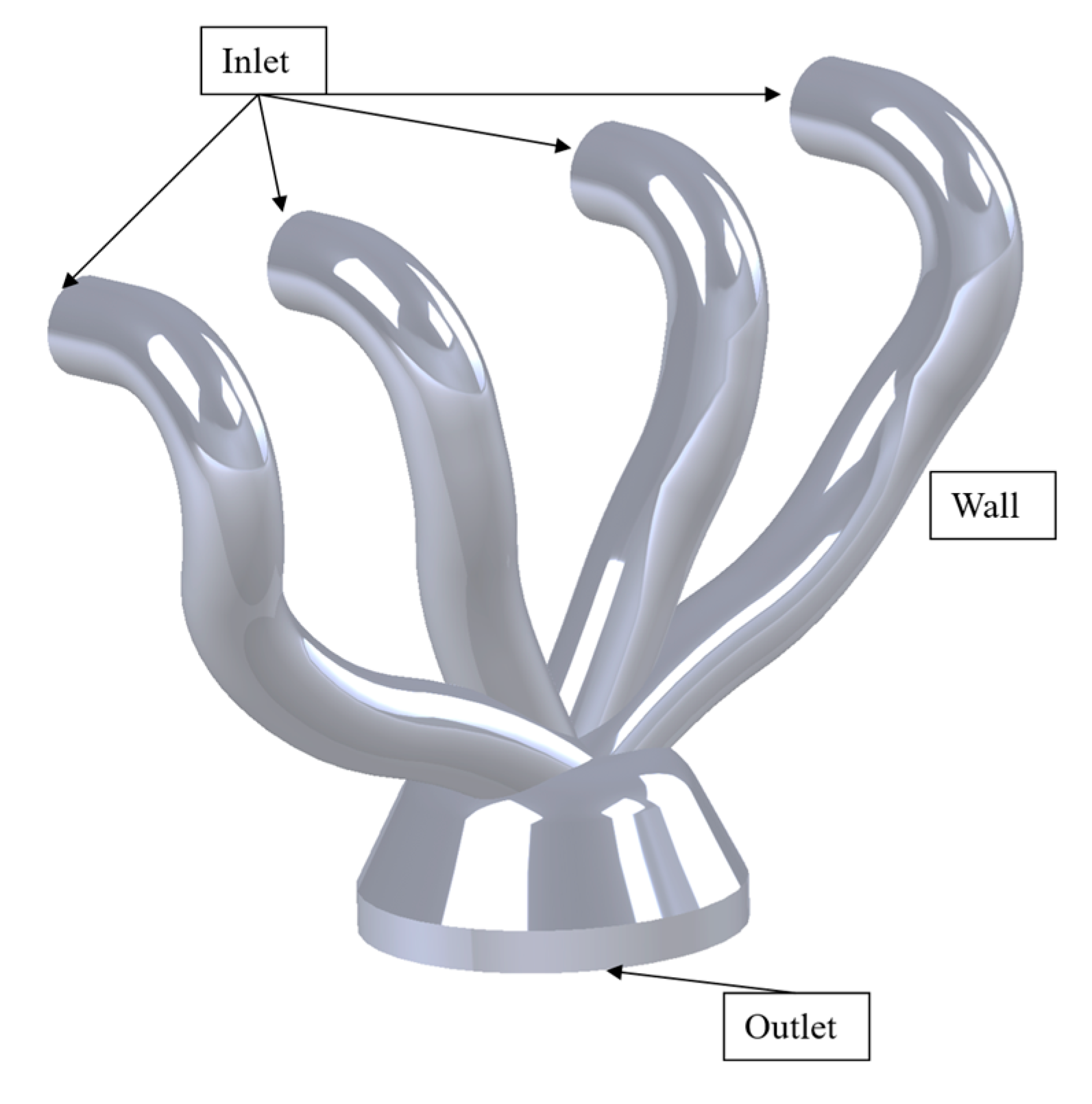
Figure 4.
Mass flow rate at the exhaust manifold outlet.
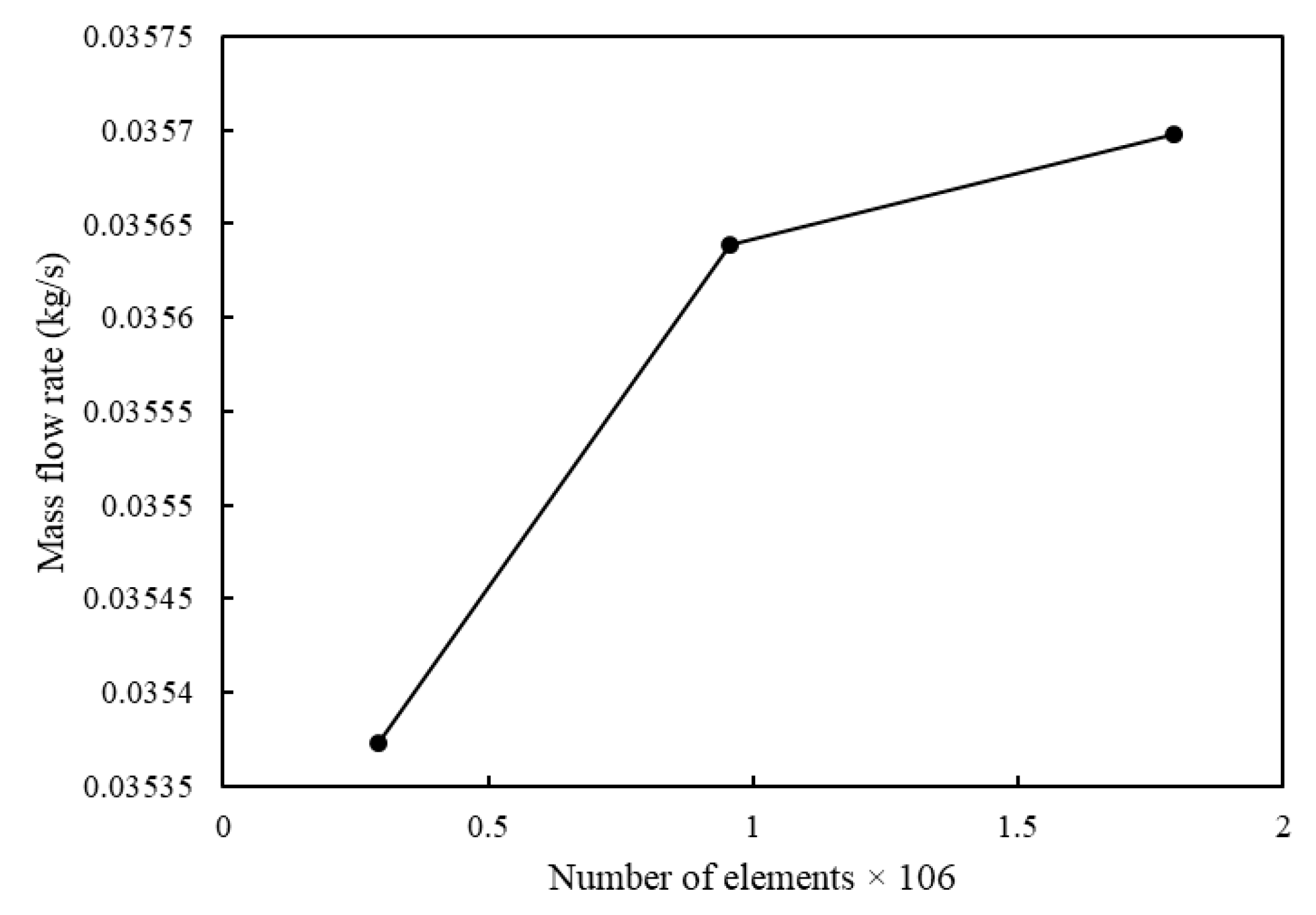
Figure 5.
Static pressure contour.
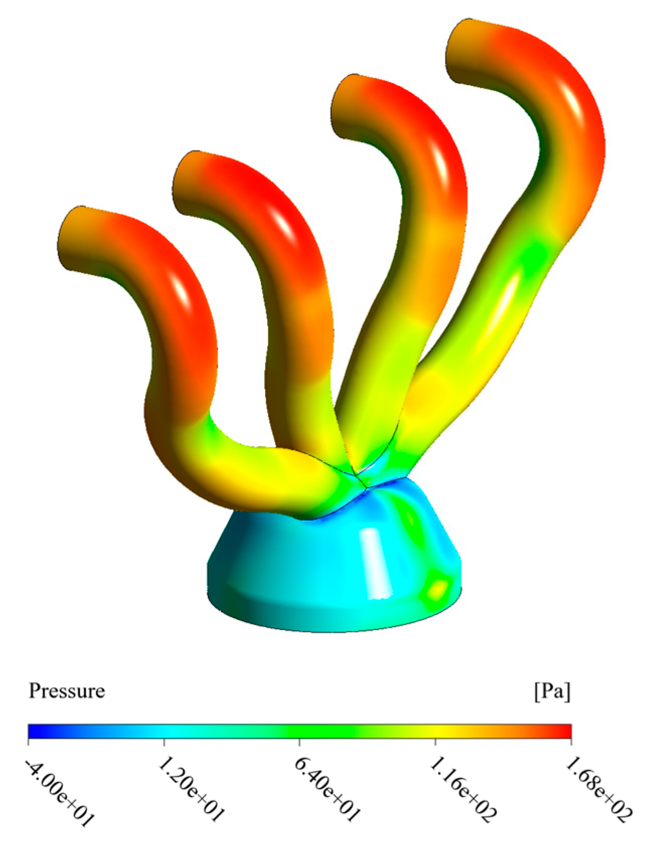
Figure 6.
Output speed value contour.
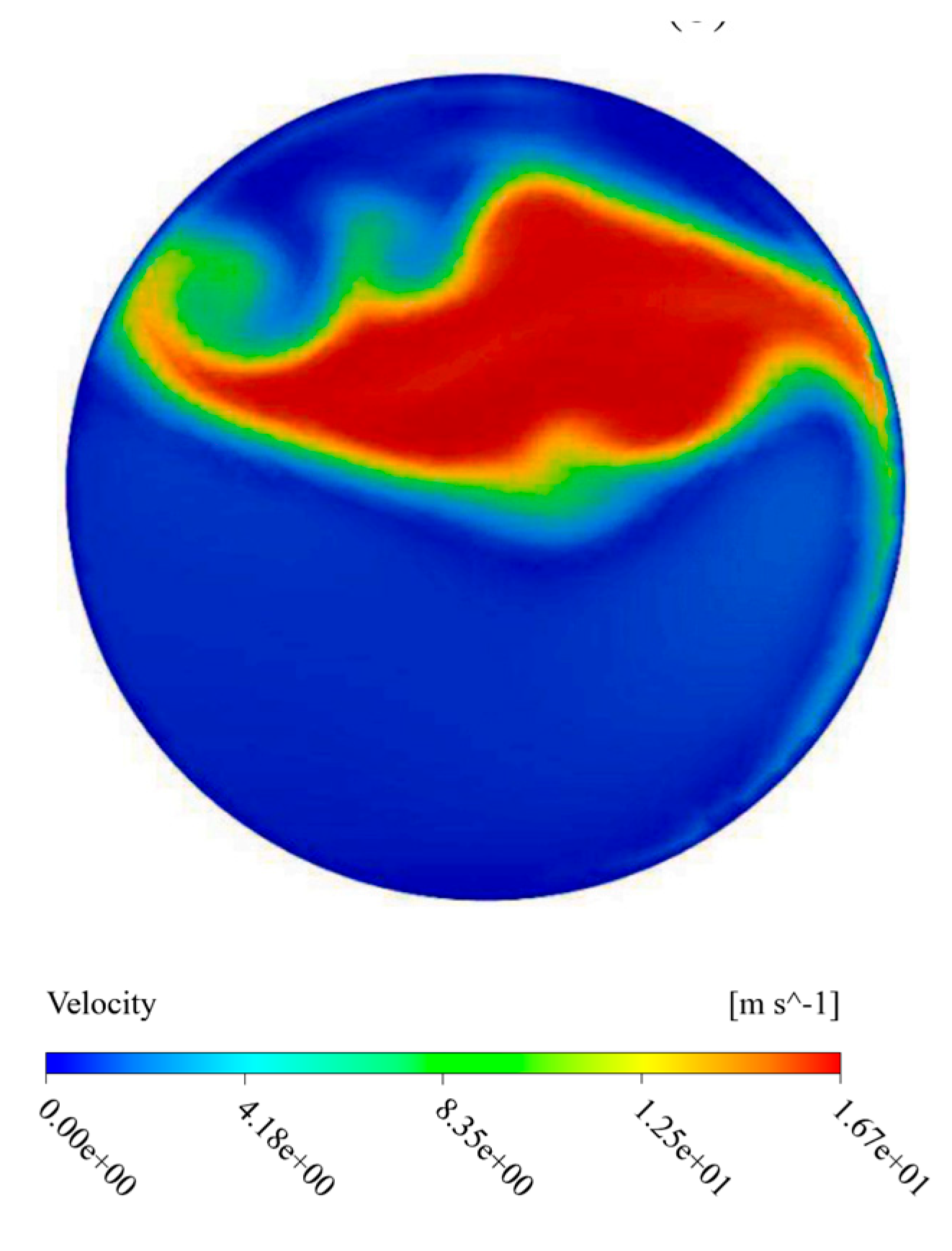

Table 1.
Pressure Drop Values.
| Outlet Total Pressure (Pa) | Average Inlet Total Pressure (Pa) | Total Average pressure drops (Pa) |
Pressure Drop Improvement (Pa) |
| 13.51 | 36.89 | 23.66 | +19.54 |
Table 2.
Standard Deviation and Flow Uniformity Index at the Outlet of the Exhaust Manifold Design.
| Weighted Area Uniformity Index (γ) | Uniformity index % |
Standard deviation |
Standard deviation % |
| 0.79 | +36.2 | 2.33 | -36.93 |
Table 3.
Pollutant Conversion Rates.
| Improvement % | Conversion % | Weighted Area Uniformity Index (γ) | ||||
| CO | HC | NOx | CO | HC | NOx | 0.727 |
| 6.9 | 3.3 | 3.2 | 83 | 78 | 85 | |
Disclaimer/Publisher’s Note: The statements, opinions and data contained in all publications are solely those of the individual author(s) and contributor(s) and not of MDPI and/or the editor(s). MDPI and/or the editor(s) disclaim responsibility for any injury to people or property resulting from any ideas, methods, instructions or products referred to in the content. |
© 2025 by the authors. Licensee MDPI, Basel, Switzerland. This article is an open access article distributed under the terms and conditions of the Creative Commons Attribution (CC BY) license (http://creativecommons.org/licenses/by/4.0/).
Copyright: This open access article is published under a Creative Commons CC BY 4.0 license, which permit the free download, distribution, and reuse, provided that the author and preprint are cited in any reuse.


