
Submitted:
06 November 2023
Posted:
07 November 2023
You are already at the latest version
Abstract
Many quantum devices signals are proportional to the number of the participating atoms that take part in the detection devices. Among these are optical magnetometers, atomic clocks, and atoms interferometers. One way to enhance the signal to noise ratio is to introduce atoms entanglement that increases the signal in a super-radiant like effect. An initial novel experiment to test the realization of atoms correlation is described here. A Cs optical magnetometer is used as a tool to test the operation of a cell-in-cavity laser and its characteristics. A vapor cell is inserted in-to an elongated external cavity of the pump laser in Littrow configuration. Higher atom polarization and reduced laser linewidth are obtained leading to better magnetometer sensitivity and signal-to-noise ratio. The Larmor frequency changes of the Free Induction Decay of optically pumped Cs atomic polarization in ambient earth magnetic field at room temperature is measured. Temporal changes in the magnetic field of less than 10 pT/Hz are measured. The first order dependence of the magnetic field on temperature and temperature gradients is eliminated, important in many practical applications. Single and gradiometric magnetometer con-figurations are presented.
Keywords:
sensing
; coherent photon states
; quantum correlations
1. Introduction
Many quantum devices signals are proportional to the number of the participating atoms N, that take part in the detection devices. Among these are optical magnetometers, atomic clocks, and atoms interferometers. One way to enhance the related signal-to-noise ratio is to introduce atoms entanglement that results in an increase of the signal in a super-radiant like effect. The resulting signal is then proportional to N2 rather than N. In this article we introduce an attempt to acquire such effect. The idea is to expose the atoms to a coherent EM field inside a laser cavity. The aim is to show lasing at resonance while there exists resonance absorption in its cavity. The hope is that atoms correlate due to the coherence of the EM field. We have recently shown theoretically [1] collective behavior of the atoms such as dressing of quantum states by the atoms, and N2 dependence of the absorption coefficients. In a brief review we describe the basics of the theory. The relevant collective Hamiltonian, a density matrix term and the many-body collective absorption coefficient showing N2 characteristics. It is shown that the collective effect depends on the number of the relevant photon namely, a strong coherent field is imperative. Nonetheless, a first step of operating a coherent field and exposing the atoms to such field even feeble is required. Such a successful attempt is described in this paper. In our experiment a hot vapor cell is employed, and the detector device is an optical magnetometer.
A first experimental test of the atoms’ correlation effect toward an improvement of the signal to noise ratio is performed utilizing the performance of an optical magnetometer. Optical magnetometers have drawn interest and many studies due to their importance in basic and applied research. The main effort is devoted to the well-known magnetically shielded Spin Exchange Relaxation Free (SERF) magnetometer [2,3,4]. In this magnetometer optical pumping is used to polarize alkali atoms with circularly polarized laser beam and any change in magnetic field is probed by a linearly polarized beam. Over the last ten years, less sensitive but unshielded magnetometers, based on the Bell-Bloom method (cw lasers) or based on measuring the Larmor frequency changes of the Free Induction Decay (FID) of the atomic polarization indued by pulsed lasers, have been developed. These devices open the way for many applications requiring a sensitivity of several pico-Tesla (pT)/√Hz at 1 Hz in measuring minute changes in ambient earth magnetic field [5,6,7]. The latter, called “pulsed magnetometer”, offers a direct measurement of the Larmor frequency, independent to first order on temperature and temperature gradients over the cell, an important and favorable feature in many practical applications. This method also avoids possible complications with the Electromagnetically Induced Transparency process (EIT), when using polarization intensity changes as a method for magnetometry [8]. Just recently, an unshielded, portable gradiometer with a sensitivity of 16 fT/cm/√Hz in open space with reduced size and lower power consumption, based on multipass cells pulsed magnetometers has been demonstrated [9].
In the present paper we present a multipass methodology based on introducing the vapor cell inside the pump-laser Littrow configuration external cavity. We show that this configuration works with AR-coated and un-coated diode lasers providing a higher and coherent polarizing field, quantum coherence of the EM field inside a cavity along with smaller pump-laser linewidth, contributing to a higher atomic polarization, better sensitivity, and better signal-to-noise ratio and possible atoms correlation [1].
2. Theoretical
Recently we have introduced a generic collective excitation exchange operator that describes photon-assisted excitation exchange, real or virtual, between two atoms and conserves the total number of excitations in the joint electromagnetic field and atoms quantum system [1]. This novel operator exhibits photon-assisted atoms correlation. It results in a new dressing of the atomic levels, i.e., dressing by the number of active atoms N. It also brings about N2 dependence in atomic parameters, such as absorption, a signature of achieving collective behavior. Another virtue of atom correlations is that they may provide the possibility of achieving the Heisenberg limit of quantum noise 1/N, rather than the standard quantum noise limit of 1/. The N-dressing process was observed in Ref [10]. Our more general theory accounts for their calculations and effectively accounts for their experimental data [11,12].
We briefly outline the results presented in [1]. For a system of N two-level atoms interacting with quantized single mode of electromagnetic field inside a resonant cavity the interaction Hamiltonian reads
Here g is a coupling constant, and are operators of creation and annihilation of photons, = |a⟩ ⟨b| is lowering operator of i − th atom. The first term is a standard interaction Hamiltonian for a two-level system driven by a resonant laser field. The second term is the novel operator describing photon-induced correlation between different atoms introduced in [1], Ωc stands for inter-atomic correlation strength. Eigenvalues of the Hamiltonian (1) are:
where is the number of photons in the cavity. These eigenvalues manifest a collective characteristic seen in the asymptotic N2 dependence at large values of N:
Similar collectivity is also manifested in the behavior of the absorption rate. We solve semiclassical equations for the atomic density matrix derived from the Hamiltonian (1) and calculate the absorption rate contained in the equation for the number of photons [1]:
In Figure 1 the absorption rate a is plotted as a function of the number of atoms. This is a clear indication of the effect of the correlation on the absorption rate and of the collective signature at large number of atoms. The ratio of the absorption rate with correlations a(Wc) to a(0) at large number of atoms scales as
The atomic correlations inhibit the absorption by a factor of N2 and consequently enhance the gain by a factor of N2.
3. Experimental
A Cs vapor cell is introduced in the external cavity of a diode laser operated in Littrow-Melbourne configuration [13] as shown in Figure 2. The output laser beam is spectrally narrowed and tuned to resonance. The setup includes a CW, AR-coated diode laser at Cs D2 line @852nm (Toptica LD-0860-0080-AR-1, 90 mW), an f11 aspheric lens, a cylindrical Cs vapor cell of 25 mm diameter and 50 mm length lens containing 5 Torr of Nitrogen, 7.5 torr Ne and a drop of Cs (Sacher Lasertechnik), an 1800 grooves/mm holographic diffraction grating and a folding mirror. The cavity length is approximately 30 cm long. The fluorescence produced in the cell by the resonant tuned laser beam is photographed and displayed in Figure 2 along with laser’s spectrometer trace and wave-meter measurement. The extended external cavity reduces the laser linewidth from several hundred GHz to several tens of MHz. As expected, the longer the cavity, the smaller the linewidth [14]. The fluorescence in the relatively low-pressure vapor cell is an indication of the tunned wavelength to resonance. As one can see in the figure, the original laser radiation of ~5 nm at FWHM is reduced to less than 1 pm as measured by a HighFinesse WS-6 wavemeter. The diode laser linear polarization is vertical and so are the grating grooves. In this specific measurement, the diode laser is AR coated and the vapor cell is uncoated, but similar operation is observed with uncoated diodes, although less efficient. A similar operation of a pulsed diode laser with a vapor cell inside the external cavity was demonstrated too.
The heart of a pulsed magnetometer is the employment of short-pulse pump laser (less than 200 ns pulse duration) followed by the Free Induction Decay of the Cs atoms polarization pulse [15]. To increase optical pumping efficiency, we introduced an un-coated Cs vapor cell inside the pulsed pumping diode laser external cavity in a configuration like that shown in Figure 2.
For the pulsed magnetometer a multimode, broadband (~100 GHz), high-power pulsed laser diode, Intense 2150-9mm-89505, vertically polarized, is used with the elongated external cavity and in-cavity vapor Cs cell detailed before. The laser is resonant to Cs D1 line at 895 nm, operated at 1-5 kHz repetition rate of 100-300 ns pulses. The pulse duration is limited by the manufacturer and was not optimized. Preliminary results show that using longer pulse duration up to 1μs, with the same energy per pulse, increases the Cs polarization but jeopardizes the diode [16]. The peak pump laser power during the pulse is several watts.
A λ/4 waveplate, WP1, is added inside the cavity to circularly polarize the laser entering the vapor cell to optically pump the atoms. A second λ/4 waveplate, WP2, with its axis parallel to the first one, is added after the cell to turn the circular polarization into a horizontal linear polarization, preferable for S first order reflection from the vertically grooved Littrow grating [17]. This setup is shown in Figure 3. An analysis of the pump laser polarization through the cavity is done by Jones matrices [18].
For simplicity in matrix presentation, we rotate the whole system by 45o. Let’s assume that the initial laser polarization vector is , (6)
The Jones matrix of a λ/4 waveplate is: (7)
The Jones matrix of a mirror is: (8)
The Jones matrix of the light path from the diode laser to the Littrow grating and back to the diode laser is represented by the product.
Leading to the laser polarization vector entering back the diode:
The result of a detailed calculation of the product (9) using (6-9), positioning the plates WP1 and WP2 such that their main axes are relatively parallel, is that the atomic polarization increases with each passage of the laser beam in the cell, for both directions of beam propagation. As shown in Figure 4, the circular polarization of the reflected beam inside the cell is in the same direction as the original beam, increasing atoms polarization.
The transverse polarization of the Cesium atoms is measured by detecting the optical rotation induced by the paramagnetic Faraday rotation of the linearly polarized probe light, propagating through the atomic vapor perpendicular to the pump beam as shown in Figure 3. We use a balanced polarimeter setup comprising a Wollaston prism and a Thorlabs’ PDB210A - Large-Area Balanced Photodetector. The probe laser is a Toptica LD-0852-015 DFB-1 CW, low power (<15 mW), narrow bandwidth distributed feedback laser diode (DFB) linearly polarized, detuned by approximately 10 pm from the Cs D2 line at 852 nm, furthermore, linearly polarized by a Glan-Laser polarizer for a higher contrast ratio. The probe power and detuning have been optimized for highest signal and so are the two λ/4 waveplates orientation.
The acquired raw data consists of a series of FID waveforms at pump pulses repetition rate, with a period T (e.g., one millisecond at 1 kHz). The functional form of the waveform (Wf) as shown in Equation 11, is obtained from solving the Bloch equation for polarization.
The decay constant ℾ is the reciprocal of the sum of all decay rates of the polarization, and the oscillation frequency f is the Larmor frequency of the ground level of the cesium atom. Assuming constant frequency for the waveform in the ith period, (i-1)T<t<iT for i=1 to N (N is the total number of pulses per measurement), we calculate the Larmor frequency fi (proportional to the magnetic field) by either zero crossing or Interpolated Fourier Transform (FFT) algorithms. Defining the function F(t)=fi-average(fi) for (i-1)T<t<iT, for i=1 to N, we convert it to Magnetic field values B(t) using the gyromagnetic ratio of Cs, and calculate its Power Spectral Density (PSD) and Amplitude Spectral Density (ASD) in the frequency domain:
𝑃𝑆𝐷𝐵(𝑡) (𝜔)=2∙𝑇/𝑁∙a𝑏𝑠(𝐹𝐹𝑇𝐵(𝑡)(𝜔))2 for ω= (1...N/2)/T; dimensionality: Tesla2/Hz
𝐴𝑆𝐷𝐵(𝑡)(𝜔)=√𝑃𝑆𝐷𝐵(𝑡)(𝜔); dimensionality: Tesla/√Hz
The noise floor of the measurement is the ASD outside the signal peaks. B2, the square of magnetic field intensity at an ASD peak, is obtained by integrating the PSD over the peak. The proven bandwidth of our pulsed magnetometer operated at 1 kHz, is 0.01-500 Hz with 225 Hz at -3dB and its dynamic range is 20-100 mT.
Figure 5 compares ASD spectra measured in two experiments: one with the cell inside laser cavity and one with the cell outside the cavity. External magnetic fields of 1.8 nT at 13 Hz and 11.3 Hz were applied on the cell inside the cavity as well as on the cell outside the cavity, respectively. One can see that the noise floor is lowered by introducing the cell inside the cavity without affecting applied field intensity measurement. Other peaks appearing in the spectra are at 50 Hz and its harmonics existing in the laboratory.
A similar magnetometer configuration is used for gradiometric measurements. For a small base-line magnetometer, the probe beam is split in two equal and parallel beams depicting atoms polarization by crossing a single vapor cell through two separate lines separated by a short distance as shown in Figure 6 A. For large base-line gradiometer, the probe beam split in two, crossing two separate cells, the two of them located inside the external cavity of the pump laser at 10-15 cm distance, as shown in Figure 6 B.
An amplitude spectral density (ASD) of 10 pT/√Hz of a single magnetometer at frequencies higher than 10 Hz was measured in the laboratory. ASD of less than 10 pT/√Hz at 1 Hz has been demonstrated in the laboratory in gradiometric configuration with a 1.5 mm baseline, operated at 1 kHz of 200 ns pulses and 8-100 s of data acquisition time. Results of such a gradiometric measurement are shown in Figure 7. Better sensitivity is expected outdoors, far from buildings noise.
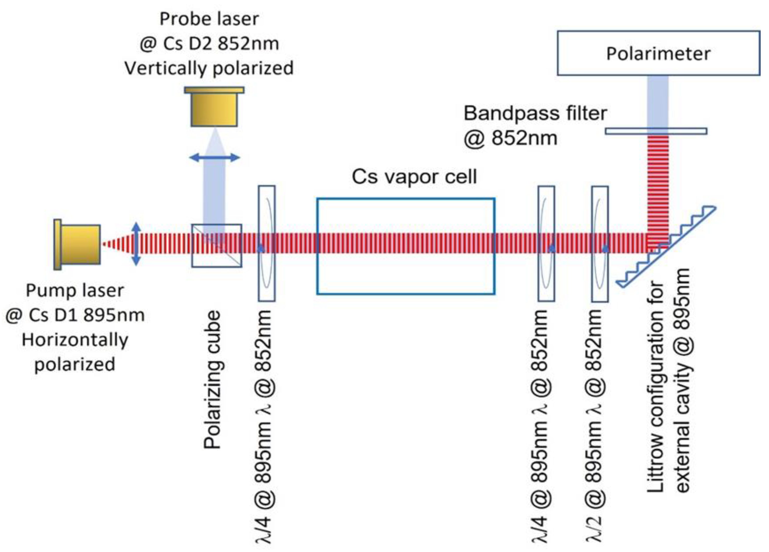
For higher Signal-to-Noise (SNR), a co-linear configuration of the pulsed magnetometer with a vapor cell inside the pump laser cavity is used, as shown in Figure 8. Besides the main elements shown in Figure 3, this setup includes a polarizing cube, special dual wavelengths waveplates of λ/4 at 895 nm and λ/2 at 852 nm, and a bandpass filter at 852 nm.
4. Summary
A crucial novel step for realizing quantum application of a vapor cell inside a lasing cavity is performed. Note that several optics elements related to the magnetometer function is also introduced in the cavity which decreases n, the coherent photon number exposing the atoms. Yet coherent EM field at resonance is achieved. As seen in the theory, the correlation process is proportional to the field intensity. Thus, a required next step is essential increase of the coherent field. The effect of the cavity is in providing the length of time for exposing the atoms to the coherent field and for establishing atoms correlation. Also, we propose a much better physics arena for realizing the quantum application: cold atom devices.
Successful first step operation of a cell-in-cavity laser is achieved towards experimental quantum applications and demonstrated in an optical magnetometer.
A Cs vapor cell was introduced in the cavity along with two quarter wavelength waveplates, as part of a perpendicular pulsed magnetometer. In both parallel and perpendicular λ/4 waveplates relative orientation, the laser reflected backwards in first-order Littrow configuration, enters the diode laser with the same polarization as the original one locking the laser to the desired wavelength.
The internal cavity reflections along with the relatively long cavity narrowing laser linewidth, make an efficient atomic pumping. A maximum magnetometer signal is obtained with two parallel aligned waveplates at 45° to the original vertical laser polarization. The highly reflected S polarization in the Littrow configuration increases the intensity of the circular-polarized laser between the waveplates inside the cell. The cell-in-cavity configuration increases atoms’ polarization and increases signal-to-noise ratio. Higher pump laser power, AR-coated cell as well as an AR coated diode laser, may further improve the signal.
Author Contributions
Conceptualization, Reuben Shuker and Andrei Ben-Amar Baranga; Methodology, Reuben Shuker and Andrei Ben-Amar ; Software, Gennady Koganov and David Levron; Validation, Andrei Ben-Amar Baranga and Reuben Shuker; Formal analysis, Gennady Koganov, David Levron and Reuben Shuker; Investigation, Andrei Ben-Amar Baranga and Gabriel Bialolenker; Resources, Reuben Shuker; Data curation, Andrei Ben-Amar Baranga, Gennady Koganov and David Levron; Writing—Andrei Ben-Amar Baranga, Gennady Koganov and Reuben Shuker; Writing—review and editing, Andrei Ben-Amar Baranga; Visualization, Andrei Ben-Amar Baranga; Supervision, Reuben Shuker; Project administration, Reuben Shuker; Funding acquisition, Reuben Shuker.
Funding
Ben-Gurion University of the Negev, internal funding. This research received no external funding.
Institutional Review Board Statement
Not relevant.
Informed Consent Statement
Not applicable.
Data Availability Statement
Data Availability at request.
Acknowledgments
None.
Conflicts of Interest
The authors declare no conflict of interest.
References
- Shuker, R.; Koganov, A.G. Photon-induced correlations of quantum systems via an excitation exchange operator. Laser Physics Letters 2021, 18, 055205. [Google Scholar] [CrossRef]
- Allred, J.C.; Lyman, R.N.; Kornack, T.W.; Romalis, M.V. High-Sensitivity Atomic Magnetometer Unaffected by Spin-Exchange Relaxation. Phys. Rev. Lett. 2002, 89, 130801. [Google Scholar] [CrossRef] [PubMed]
- Kominis, I.K.; Kornack, T.W.; Allred, J.C.; Romalis, M.V. A sub-femto-tesla multichannel atomic magnetometer. Nature 2003, 422, 596–599. [Google Scholar] [CrossRef] [PubMed]
- Budker, D.; Jackson Kimball, D.F. Optical Magnetometry; Cambridge University Press: Cambridge, UK, 2013. [Google Scholar]
- Ben Amar Baranga A., Levron D., Paperno E. and Shuker R., United States Patent US 10,712,407 B2, July 14, (2020).
- Romalis M., Haifeng Dong and Baranga A. United States Patent US 10,852,371 B2 Dec. 1, (2020).
- Gerginov, V.; Pomponio, M.; Knappe, S. Scalar Magnetometry Below 100 fT/Hz1/2 in a Microfabricated Cell. IEEE Sensors Journal 2020, 20, 12684–12690. [Google Scholar] [CrossRef] [PubMed]
- Ben-Amar Baranga, A.; Gusarov, A.; Koganov, G.A.; Levron, D.; Shuker, R. Optical magnetometer: Quantum resonances at pumping repetition rate of 1/n of the Larmor frequency. Jour. of App. Phys. 2020, 128, 174501. [Google Scholar] [CrossRef]
- Limes, M.E.; Foley, E.L.; Kornack, T.W.; Caliga, S.; McBride, S.; Braun, A.; Lee, W.; Lucivero, V.G.; Romalis, M.V. Portable Magnetometry for Detection of Biomagnetism in Ambient Environments, Phys. Rev. Appl. 2020, 14, 011002 pp1-6. Campbell K., Wang Y. J., Savukov I., Jau Y. Y., Schwindt P., Shah V., "Pulsed gradiometry in Earth's field", APS DAMOP, June 2020.
- Colombe, Y.; Steinmetz, T.; Dubois, G.; Linke, F.; Hunger, D.; Reichel, J. Strong atom–field coupling for Bose–Einstein condensates in an optical cavity on a chip. Nature 2007, 450, 272–276. [Google Scholar] [CrossRef] [PubMed]
- Koganov, A.G.; Shuker, R. Double dressing by both the number of atoms and the number of photons inside cavity. Results in Physics 2023, 49, 106447. [Google Scholar] [CrossRef]
- Koganov A., G. and Shuker R., manuscript in preparation.
- Hawthorn, C.J.; Weber, K.P.; Scholten, R.E. Littrow configuration tunable external cavity diode laser with fixed direction output beam. Rev. Sci. Instrum. 2001, 72, 4477–4479. [Google Scholar] [CrossRef]
- Jechow, A.; Raab, V.; Menzel, R.; Cenkier, M.; Stry, S.; Sacher, J. 1 W tunable near diffraction limited light from a broad area laser diode in an external cavity with a line width of 1.7 MHz. Opt. Commun. 2007, 277, 161–165. [Google Scholar] [CrossRef]
- Gusarov, A.; Levron, D.; Baranga, A.; Paperno, E.; Shuker, R. An all-optical scalar and vector spin-exchange relaxation-free magnetometer employing on–off pump modulation. J. Appl. Phys. 2011, 109, 07E507. [Google Scholar] [CrossRef]
- Ben Amar Baranga A. private communication.
- Palmer, C. Diffraction Grating Handbook, 8th ed; MKS Instruments, Inc.: Rochester, New York, NY, USA, 2020; pp. 122–126. [Google Scholar]
- Brosseau, C. Fundamentals of Polarized Light; John Wiley & Sons Inc.: New York, 1998; pp. 181–209. [Google Scholar]
Figure 1.
Absorption rate α as a function of the number of atoms N for no correlation Ωc = 0 (black dashed line), in presence of correlation Ωc = 0.0001 (red dash-dotted line) and Ωc = 0.001 (blue solid line).
Figure 1.
Absorption rate α as a function of the number of atoms N for no correlation Ωc = 0 (black dashed line), in presence of correlation Ωc = 0.0001 (red dash-dotted line) and Ωc = 0.001 (blue solid line).
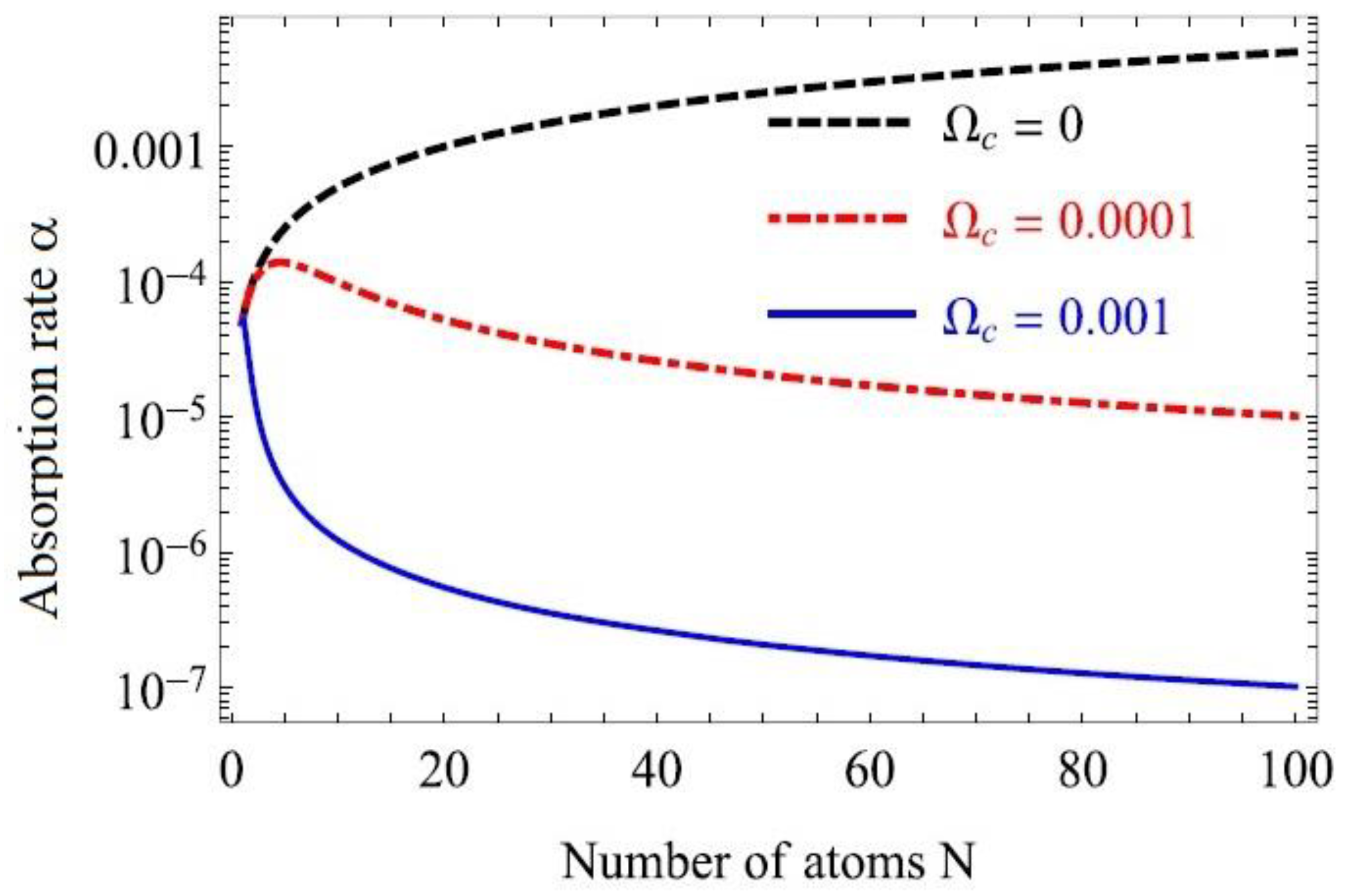
Figure 2.
Diode laser with a Cs vapor cell inside the elongated external cavity. Shown are the fluorescence through the cell at resonant D2 line, the laser spectrum recorded by a spectrometer and the wavelength measured by a wavemeter.
Figure 2.
Diode laser with a Cs vapor cell inside the elongated external cavity. Shown are the fluorescence through the cell at resonant D2 line, the laser spectrum recorded by a spectrometer and the wavelength measured by a wavemeter.
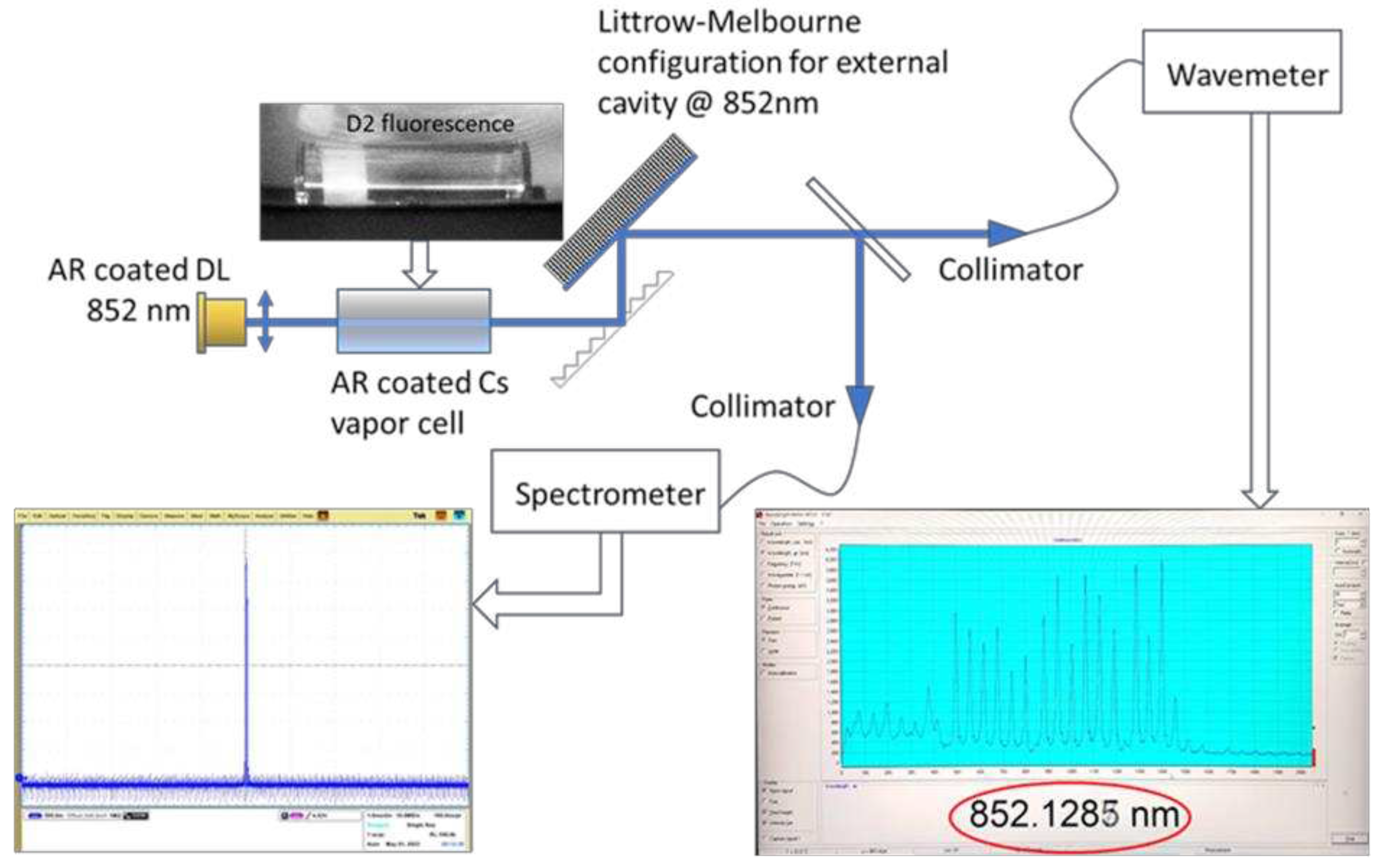
Figure 3.
Pulsed magnetometer with the vapor cell inside the pump laser cavity. The probe laser is perpendicular to the pump.
Figure 3.
Pulsed magnetometer with the vapor cell inside the pump laser cavity. The probe laser is perpendicular to the pump.
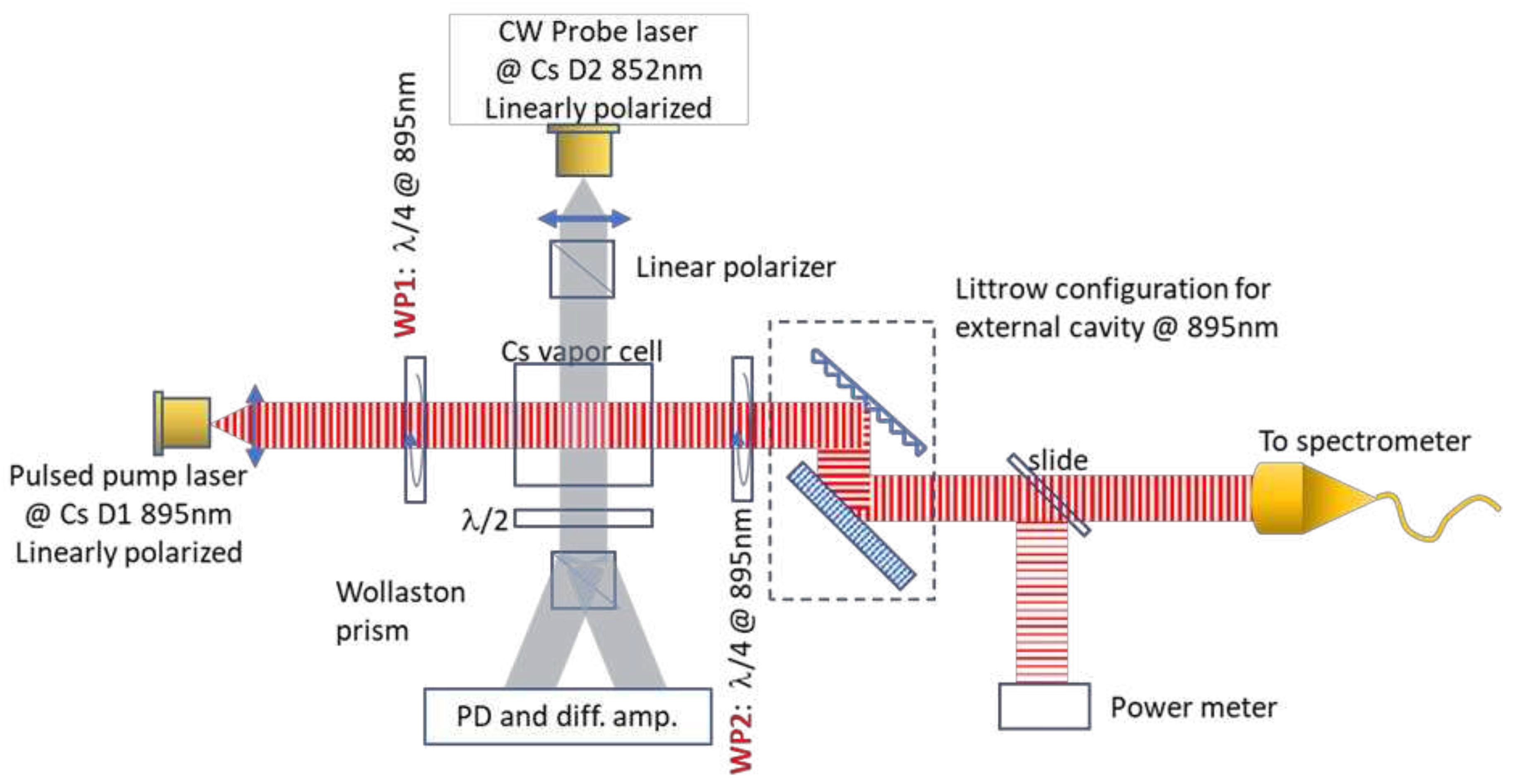
Figure 4.
Jones matrix presentation for laser beam polarization inside the Littrow external cavity.

Figure 5.
ASD of the pulsed magnetometer with the vapor cell inside pump laser cavity and outside the cavity. The noise floor is lowered by introducing the cell inside the cavity without affecting applied field intensity measurement as emphasized in the insert.
Figure 5.
ASD of the pulsed magnetometer with the vapor cell inside pump laser cavity and outside the cavity. The noise floor is lowered by introducing the cell inside the cavity without affecting applied field intensity measurement as emphasized in the insert.
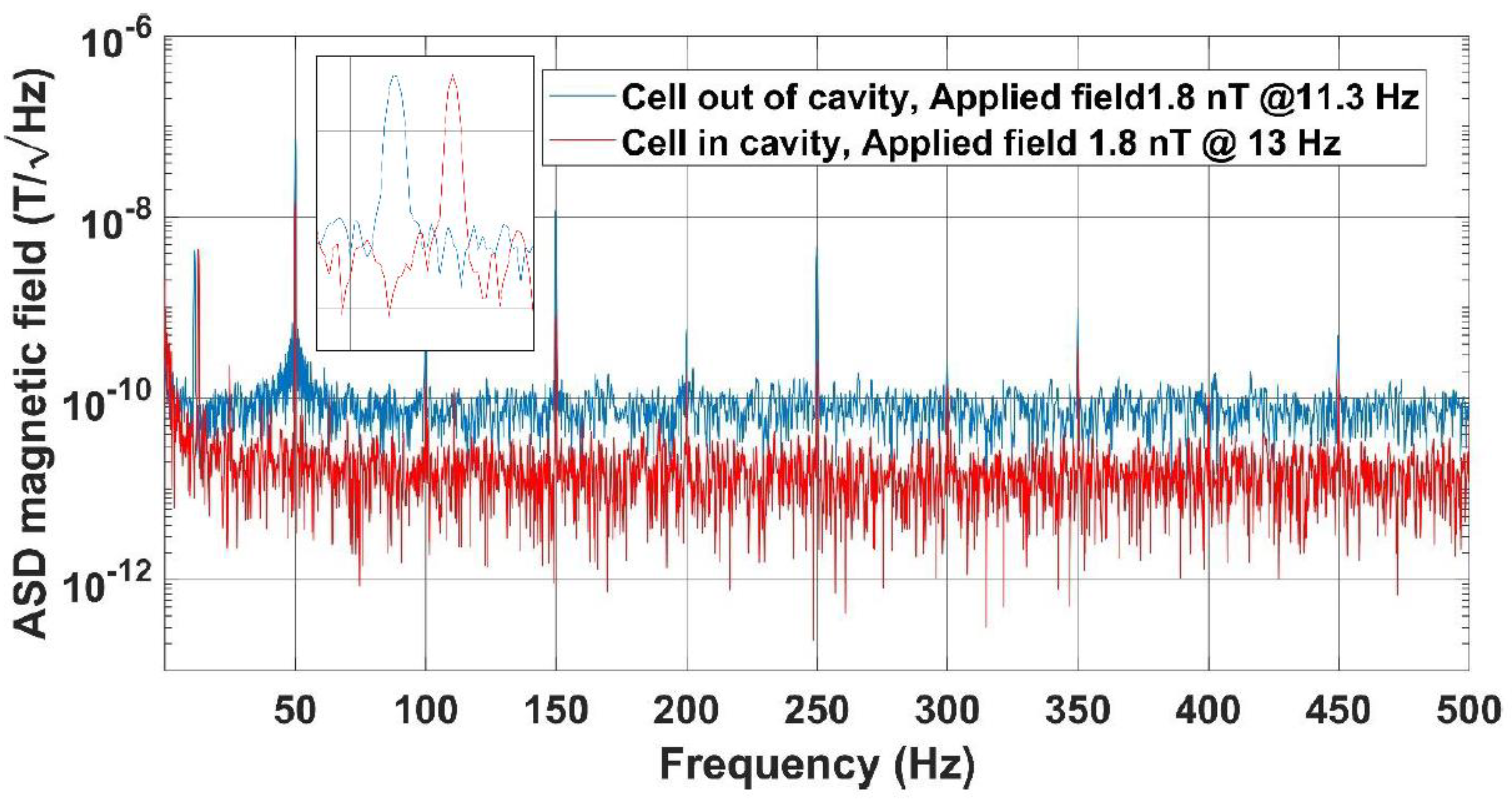
Figure 6.
A: Small base-line gradiometer, single vapor cell. B: Large base-line gradiometer with two vapor cells inside pump laser cavity.
Figure 6.
A: Small base-line gradiometer, single vapor cell. B: Large base-line gradiometer with two vapor cells inside pump laser cavity.

Figure 7.
ASD of a pulsed magnetometer in gradiometric configuration with two beams at 1.5 mm distance inside a single cell illuminated by an external cavity diode laser.
Figure 7.
ASD of a pulsed magnetometer in gradiometric configuration with two beams at 1.5 mm distance inside a single cell illuminated by an external cavity diode laser.
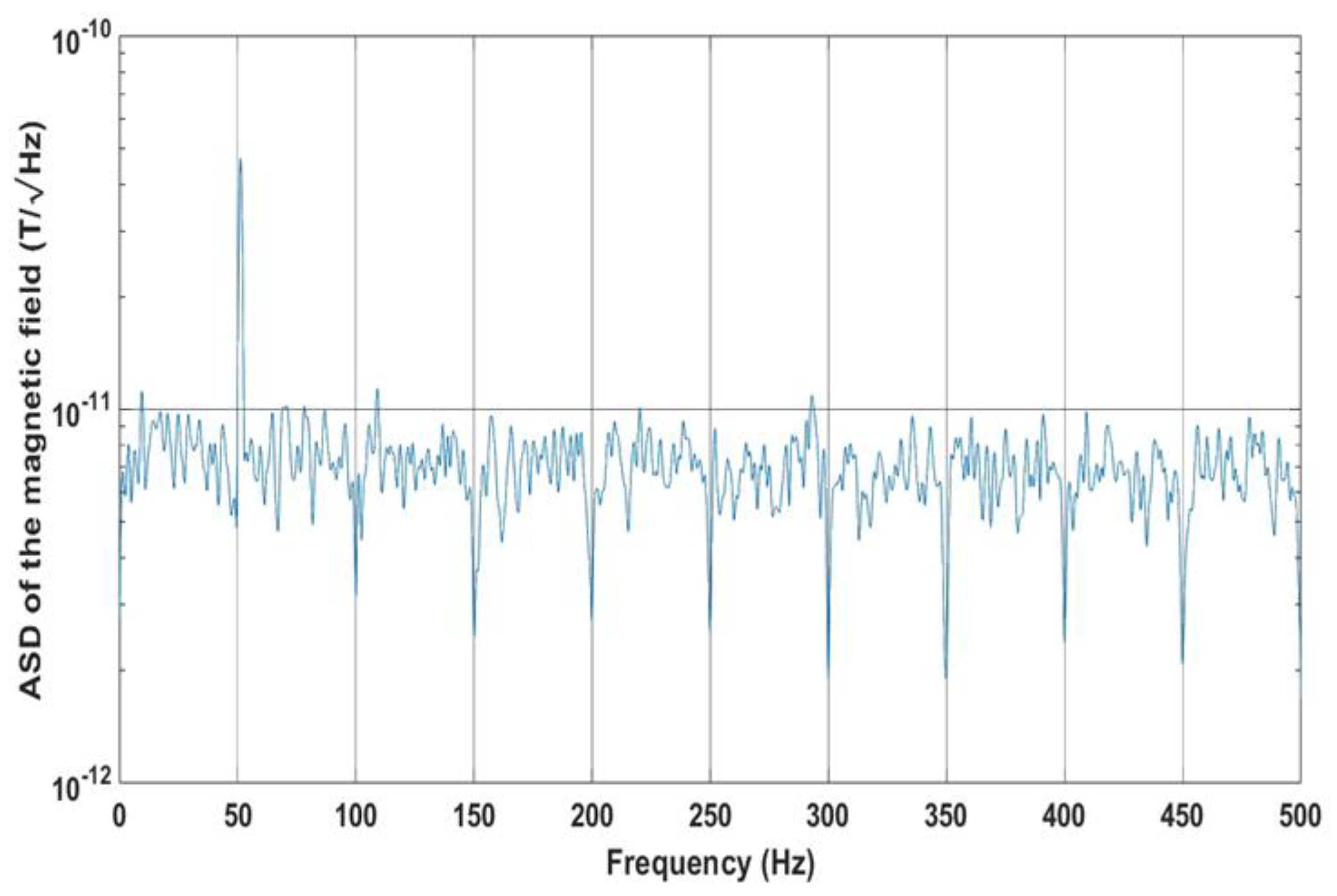
Figure 8.
Pulsed magnetometer with co-linear laser beams and vapor cell inside pump laser cavity.
Disclaimer/Publisher’s Note: The statements, opinions and data contained in all publications are solely those of the individual author(s) and contributor(s) and not of MDPI and/or the editor(s). MDPI and/or the editor(s) disclaim responsibility for any injury to people or property resulting from any ideas, methods, instructions or products referred to in the content. |
© 2023 by the authors. Licensee MDPI, Basel, Switzerland. This article is an open access article distributed under the terms and conditions of the Creative Commons Attribution (CC BY) license (http://creativecommons.org/licenses/by/4.0/).
Copyright: This open access article is published under a Creative Commons CC BY 4.0 license, which permit the free download, distribution, and reuse, provided that the author and preprint are cited in any reuse.


