
Submitted:
30 October 2023
Posted:
31 October 2023
You are already at the latest version
Abstract
Composite timber-concrete constructions are innovative structural systems which have become the subject of research and practical usage, primarily due to their attractive mechanical properties. This article deals with the experimental procedure and the analysis of the mechanical behavior of two different serious of timber-concrete composite beams. In the composite beams of the A series, screws were used as a fastening system in the interlayer between the timber and concrete parts, whereas in the B type series, a more complex system, the combination of notches and screws, was used for the same purpose. Both series were exposed to loading up to a fracture point by the means of the standard procedure (four point bending test). The mechanical behavior of the A and B-series beams was analyzed by a comparative analysis referring to: the correlation of the fracture loading and the deflection at the moment of fracture, forms and mechanisms of fracture, the development of dilatations at certain points of specific cross-sections, the displacement in the timber-concrete interlayer in the support zones, the value of shear stresses and the calculated values of the effective bending stiffness of the beams. The B-series beams where a more complex fastening system, as it was expected, showed a better mechanical behavior than the A-series beams.
Keywords:
timber-concrete structures
; experimental setup
; connecting systems
1. Introduction
Composite timber-concrete constructions are innovative construction systems which have become the subject of research and practical usage in developed countries (Scandinavian countries, Australia, the USA), primarily due to their attractive mechanical properties [1,2]. In recent years, this type of construction elements has been present in our structural engineering, mostly while reconstructing old floor structures of the buildings which are protected by law as cultural monuments, Figure 1, but also while building new floor constructions in this system. First of all, timber has a relatively high tension strength and by its coupling with concrete which has a high level of compression strength under pressure, an optimal usage of the mechanical properties of these two elements is achieved. Construction elements created in this way are of a lower weight compared to classical concrete elements, thus leading to a reduced total weight of built objects and consequently, to a better performance of buildings under seismic loadings, reducing the workload related to designing and creating the foundation. A concrete slab positioned over timber beams of a bridge construction will always protect those timber beams from the sun and other negative weather effects such as rain, snow, ice and the like. In general, composite timber-concrete construction elements can be found in new residential buildings and business premises, industrial and sports facilities, bridge constructions as well as reconstructing and refurbishment of old objects especially when a minimum modification of the construction system is required, thus preserving their authenticity [3,4].
1.1. Previous Experimental research
In recent years, a certain number of researchers have achieved and presented the results of their research work related to the mechanical performance of timber-concrete composite structures exposed to static loading up to a fracture. Such researches are significant for the estimation of the achieved degree of the composite action of timber and concrete, defining the load bearing at the limit state, as well as the very mechanism of the fracture which will be shown in one of the key components of such load bearing systems (timber, concrete, connecting systems), depending on a number of parameters. Such researches are always preceded by experimental analyses by which, in accordance with the standards, the mechanical properties of the used materials, fasteners or connecting systems are defined. The common method is so called push-out test which is necessary for defining the value of the slip modulus of a chosen connecting system [5] as well as the estimation of the stiffness of the joint created by the timber and concrete part of the coupled cross section. The most relevant researches are connected to the following:
Granham the coupled the existing timber floor construction of a multi-story residential building with a concrete slab using SFS screws. After that, he tested the performance of the modified floor structure during the period of 34 days, exposed to a constant load of 2,5 kN/m2 with the limitation of the deflection of l/333. After that, the construction was loaded up to fracture. A 11.9 times greater load than originally projected was needed to reach the fracture. Clouston [6] examines, by using the four point bending, the composite system created by glued laminated timber and concrete, with a 10m span, with a continual steel mesh inserted in three rows along the whole length of the system used as a connecting system.
Ceccotti [7,8], examines the composite system which consists of two LLD (glued laminated timber) beams, and a concrete slab, with a cross-section and geometry as in Figure 2, with a 6m span. A fastener connecting system made of reinforcement with the diameter of 18mm is installed into previously drilled holes positioned along the joint of the timber and concrete, with 150-450mm between the holes, and the spaces around are afterwards filled with epoxy resin. Before doing the static test up to the fracture, the beams were exposed, during a 5-year-long period, to a constant, long-term loading outdoors, and their performance was monitored. The fracture happened when the load was 2P=500Kn, the measured deflection in the middle of the span was 33,2mm, and the movement in the interlayer between timber and concrete in the support zone was 2,47mm. The brittle fracture due to an excessive tension strength of the timber part of the construction, was caused by a 2.44 times higher value of the load than it was originally calculated. The degree of the composite action was 87-93%. The results of the experiment are compared with the result given in the y-procedure in which the slip module values of fasteners Ko4, Ko6, Ko8 defined by push-out test were used in the calculation and good results were achieved.
Gutkowski [9,10,11,12,13,14], couples timber with concrete by using notches in timber and screws which when screwed, increase the friction power in the contacting surface of these two materials, figure 2.5.2. A common experiment of static bending up to the fracture was carried out on a model with the span of 3,51m. The degree of the composite action was 54,9-77%, there was the fracture caused by bending on the timber part of the cross- section and a very bad function of the concrete notch caused by the concrete segregation.
Lukaszewska [15,16,17,18,19], examined 5 beams, 4,8m long and with the cross section as shown in Figure 4. A triple T-section is formed by LLD beams over which a prefabricated a concrete slab is positioned and connected by using M20…160 positioned at different inter-distances. This connection is completed with steel anchors previously built in the concrete slab and specially shaped U profiles whose upper part is also built in the slab before its construction, while the lower part is connected to the upper part of the timber beams by nails.
Figure 3.
a) Composite beam of timber-prefabricated concrete type; (b) Cross section of sample (Lukaszewska 2010).
Figure 3.
a) Composite beam of timber-prefabricated concrete type; (b) Cross section of sample (Lukaszewska 2010).
According to the results of the research based on the two series of beams designed in this way, but with two different systems of coupling, she concluded that the beams with screws and steel anchors had the degree of composite actions of 60%, and in the samples where timber beams were connected to pre-fabricated concrete slab by nails, it was only 30%. In order to increase the efficiency of coupling, she suggests combining screws and steel anchors together with notches in the timber part of the composite cross-section, so that the shear force in the joint of the timber and concrete interlayer could be reduced.
Yeoh [20,21], got significant results while analyzing the performance of 11 beams 8,0 m and 10,0m long coupled by screws and notches in timber, of particular geometry (5 beams) and metal perforated and one-sided steel plate connectors, exposed to a load by bending to a fracture in the common four point bending testing. 6 beams were projected for the common exploiting loading, 3,0kN/m2 (according to regulations), and the remaining 5 were projected for an underestimated loading of 1.0 kN/m2, Figure 4. The reached degree of composite action was within the range of 87.60-99.23%. The fracture of the well-projected sample-beams happened when the loading was 2,29-2,91 times higher than the calculated one, while in the second case, that value was 1,17 -2,31. He verified the results of his experiments by a calculation analysis based on a number follow-up research of connecting systems and γ-procedure.
2. Experimental analysis of composite timber-concrete beams
2.1. Projecting models of composite timber-concrete beams for experimental research
Simple beams with the total length of 2,60m and static span of 2,50m, tested at the Faculty of Mechanical Engineering in Nis, were projected as a composite beams. A cross section of T-type, formed by coupling the glued laminated timber (spruce) [22], and concrete slab, strength class C35/45 [23,24], was chosen. Two series of three beams were chosen, depending on the type of the connection of timber and concrete.
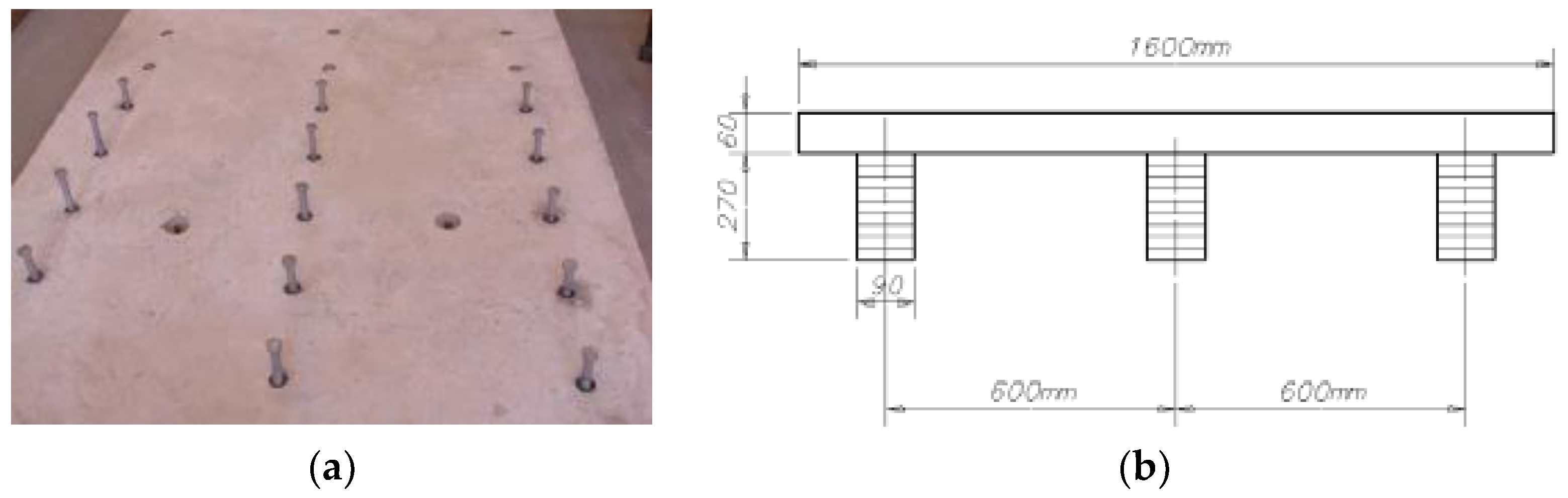
The first series of beams (A-series) is made in the traditional manner (I type of coupling), by the means of mechanical fasteners, screws, installed at the distance of 15cm from each other along the whole length of the timber and concrete interlayer. The screws are 8mm in diameter and their length is l=150mm. They are pressed into the timber part of the cross-section up to 100mm deep, Figure 5, and the remaining 50 mm are filled with concrete and remains in the concrete part of the cross-section.
The second series of beams (B-series) which was tested, was created by coupling of timber and concrete by the means of connecting system created by combining parallelopiped notch, cut in 30cm of the distance along the length of the composite beam and additional screws (II type of coupling). In the middle of the notch, screws with the diameter of 8mm and length i=180mm were used, and in the timber part of the beam, between the notches, screws l=8/150 were applied. In this way, a connecting system consisting of two screws of different lengths and a notch of 35mm depth, 150mm length and width equal to the timber beam, 100mm, was formed. In practice, the screws are again at the distance of 150mm, but participate in accepting shear force in the timber and concrete interlayer alternately, some of them directly, and the others together with the notch filled with concrete, Figure 6.
The screws are built into previously created holes with the diameter 10% smaller than the screw diameter. Prior to this, while trying to install screws without previously drilled holes, there had been a screw fracture due to a high timber quality from which glued laminated beams were made and a low moisture content of timber. The formwork for casting concrete and making composite beams is positioned on a previously prepared platform with an appropriate working height and leant on concrete floor of a hall by the means of a stable steel construction frame, Figure 7.
The formwork is made at the same time for all 12 beams. Before casting concrete into the formwork and over timber beams, into which screws were already installed and notches of certain geometry made according to the above mentioned draft, a transparent polish is applied over the upper parts of timber beams and the bottom and sides of the formwork in order to prevent water transfer from concrete into timber. In this way, the adhesion between timber and concrete parts is reduced to minimum, that is, the friction coefficient in the adherent surface of timber and concrete composite cross section is reduced which results in the biggest part of shear force in the adherent surface being taken over by the connecting systems.
The concrete of the cross section was reinforced by a steel mash (Q 131, MAR 500/560) which was, by the means of distancers, positioned 20 mm from the lower part of the concrete cross section. Concrete was, while applied, vibrated, so that the notches could be filled in a compact way, Figure 9. A lot of care was taken in order to prevent concrete segregation because of the pervibrator usage and the fact that the concrete slab was only 7cm thick.
The necessity for experimental analysis comes from the fact that, on one hand, in our country there is not a balanced standard policy concerning the timber quality, and on the other, that the analytic expressions (EC5) are not in accordance with the quality of materials.
By an experimental analysis [25,26], a correlation of results in an analytic, numerical and experimental sense, would be established and more accurate conclusions would be reached. Experimental testing of the mechanical properties of timber and concrete built in beam models, as well as testing of relocations of the applied adhesions are described in Chapter 4 in detail. These laboratory tests were carried out to reach a more accurate initial formulation of numerical models of two beam systems with different systems of coupling. The testing and defining of the necessary mechanical parameters were carried out in the laboratory of the Faculty of Civil Engineering and Architecture as well as the Faculty of Mechanical Engineering in Nis. The final geometry of the tested beams of A and B-series and the locating of the measurement types and equipment are given in Figure 10.
2.2. The experiment setup and the program of testing of the projected types of composite beams
The testing of the performance of the composite beams of the A and B series under a short trial loading up to the fracture was carried out in the laboratories of the Faculty of Civil engineering and Architecture and the Faculty of Mechanical Faculty in Nis. The Laboratory of Mechatronics at the Faculty of Mechanical Engineering did the machine laboratory test, while the Faculty of Civil Engineering and Architecture Nis, whose experts were engaged in this project, tested six composite timber-concrete beams in their laboratory using measure equipment, Figure 11, Figure 12 and Figure 13.
2.2.1. Loading procedure
Loading was done by a hydraulic device, transferring the loading onto the beam as two concentrated forces which act on the third of the span, on the internal distance of 833 mm. Such a configuration of the loading is known as “four point load”. For the transfer of the load from the hydraulic part, a 1m long steel rail was used, while the introducing of the load into AB beam was done by 100mm wide and 300mm long steel slabs and the steel roll with the diameter of 30mm positioned in between. The beam was supported by steel contact slabs with the same geometric properties and specially designed steel parts necessary for providing adequate spatial position of the beams with the T cross-section. The loading had a time mode, that is, a constant increase of the deflection in the time function, up until the moment of fracture. The loading speed was 1mm/min.
2.2.2. The testing results of the composite beams of A-series
In the Figure 14, there is a graphic presentation of the configuration of the experimental procedure of the composite timber-concrete beam of A type (marked as BF) with the instrument marks and the position of the measuring points. There is a detailed description of the measuring points in the Table 1 in accordance with the Figure 12, Figure 13 and Figure 14.
2.2.3. The testing results of the composite beams of the B-series
In the Figure 15, there is a graphic presentation of the configuration of the experimental procedure of the composite timber-concrete beam of the B series (BN-i) with the marking and the position of the measurement points. In the Table 2, there is a detailed description of the measuring points as in the Figure 15.
3. Results
3.1. The loading-deflection diagrams, (F-u) of A-series beams
In the Figure 16, the interconnection of the loading and deflection in the middle of the composite beams of A-series is shown. In the case of BF-1, as the first one to be tested, but it was later continued up to the moment of the explicit fracture. The result of this action is the diagram with an obvious discontinuation on the F-u function (loading–deflection). At the point of failure, there was a timber fracture due to an excessive stress tension in the middle of the span and fractures on the side edges in the lower part of the concrete slab. The failure of the connecting systems (screws), due to an excessive the embedding strength of the timber and of the bending stress of the screw is one more element in the complete picture of the fracture of the tested samples of the A-series. In the support zone, there was a 4-4,5mm displacement in the interlayer between the timber and concrete part of the beam which is a direct consequence of the excessive above mentioned stresses.
At the moment of fracture, A-series beams had a deflection of 35,73-44,74 mm range in the middle of the span, which is L/70-L/55,87(L is the span of beans) with the coefficient of variation of 11,3%. Despite certain irregularities of the functions which define the loading–the deflection connection, we can conclude that that correlation is approximately linear up to the fracture point and that is the proof of the linear-elastic behaviour of composite timber-concrete beams of this series.
3.2. Loading-deflection diagrams (F-u) of the B series beams
In the Figure 16 the correlation between loading and deflection in the middle of the span of the B-series beams is shown in the diagrams. The beams of this series showed a very steady performance related to the mechanical and deformity parameters.
At the moment of fracture, the B-series beams had, in the middle of their span, a deflection within the range of 18,36–20,42mm, that is L/136–L/122,42, with the variation coefficient of 5,3% and 5% of divergence of the applied loading at the moment of fracture when compared to the achieved mean value.
An almost linear deformity increase (deflection in the middle of the span), resulting from an increased loading application, indicates an ideal linear-elastic behaviour of the B-series beams, up to the moment of fracture. The reasons for such a phenomenon lie in the choice of the connecting systems used for coupling the timber and concrete part of a composite beam, the high value of achieved stiffness and the fact that beams of a short span were used in the experiment.
In the Figure 18 there is a comparative presentation of the loading intensity which caused the fracture of the ‘’B’’ series composite beams (BN-1, BN-2, BN-3). On the basis of the achieved results, the mean value of the fracture force for this series (BN-mv) was calculated. We can notice a similarity of the values of the fracture loading in the tested samples. The composite timber-concrete beams of this series are coupled by a more complex connecting system, which enabled a high stiffness degree of that interlayer and created a homogenous cross-section in which the mechanical properties of the cross-section elements are used up to a maximum point.
In the picture Figure 17 there is a presentation of the maximum reached deflections at the moment of fracture of the ‘’B’’ series composite beams (BN-1, BN-2, BN-3). On the basis of the measured values, a mean value (BN-mv) of the maximum deflection in the middle of the span of the BN beams is calculated.
3.3. Stiffness of the A-beams series
The beam stiffness is calculated for their linear-elastic performance. For each sample and the corresponding loading-deflection function, the area between 0,1 Fmax and 0,4 Fmax was analyzed in order to calculate the linear part of the function. According to the equation for the deflection calculation in the middle of the simple beam loaded by two concentrated forces in the thirds of the span, the bending stiffness El can be calculated as:
where are:
F1 loading which corresponds to 0,1 Fmax value,
F2 loading which corresponds to 0,4 Fmax value,
w1 deflection value measured for the 0,1Fmax loading value
w2 deflection value measured for the 0,4Fmax loading value.
l beam span.
The values of bending stiffness of all samples of the A-series are shown in the Table 3.
In the Figure 19. the stiffness of beams (El) of the composite beams of A-series (BF-1, BF-2, BF-3), calculated for their linear-elastic behavior is presented. On the basis of the calculated stiffness values of some samples of the A-series, the mean value of stiffness of this series of beams (BF-mv) is calculated and it is shown i Table 3.
3.4. Stiffness of the B- series beams
The beam stiffness is calculated for their linear-elastic behaviour. For each sample and the corresponding loading-deflection function, the range between 0,1Fmax and 0,4Fmax was analyzed in order to calculate the linear part of the function. The values of stiffness bending of all B-series beams are shown in Table 3.
In the Figure 19, there is a presentation of bending stiffness (EI) of the B-series beams, calculated for their linear-elastic behaviour. On the basis of the calculated bending stiffness values of the A-series samples, the mean value of bending stiffness (BF-sr) of this beam series was calculated.
3.5. Comparative analysis of the results of the experimental research of the A and B-series of composite beams
In this chapter, we will deal with the comparative analysis based on the above mentioned results of the experimental testing of the A and B-series of composite beams, and their behaviour related to the stress-strain aspect.
Table 3 presents individual and mean comparative values of the most significant parameters by which we can describe the properties and mechanism of the fracture (the fracture force, the values of the internal forces in characteristic cross-section, deflection value in the middle of the span, displacements between the timber and concrete coupled cross-section, bending stiffness). The given values were obtained by measuring or calculated for the fracture loading. The presentation of the experimental results for all the beams of A-series is shown in the Table 3. The maximum loading (fracture loading) is presented as maximum internal force values in the characteristic cross-sections (Mmax, Tmax) as well as the size of the maximum elastic deflection, together with the corresponding horizontal displacement in the interlayer between the timber and concrete part at the moment of fracture. The adequate values of the loading (Fmax), deflections and horizontal dilatation were taken from the experimental data bases, and the values of bending moment at the point of fracture (Mmax) and transversal forces at the moment of fracture (Tmax) were calculated from the analytic equation for a simple beam loaded by two concentrated forces in the thirds of the span.
In this equation, Fmax is the loading at the moment of fracture applied by the equipment and l is the span of the composite beam.
The mean value of the loading at the moment of fracture for the A-series samples was 80,65kN with the coefficient of the variation of 14%. The big loading difference at the moment of fracture of BF-1 and BF-2 samples indicates a high level of variability of strength of the glued laminated timber which was used for forming the coupled beams and the above mentioned fact related to the previous estimation of the fracture of the BF-1, that is, the previous result record. Taking into consideration the nature of timber, such a behaviour is expected in this experimental procedure. We should emphasize that, before the testing, a difference in the quality of lamella of the timber part of the two samples of the A-series was visible.
In real constructions which have to comply with certain conditions of load bearing capacity and serviceability, the calculation procedure, based on characteristic values of strengths defined on the basis of 5% fraktil of the normal distribution of the experimental results and a partial safety coefficient, guarantees their compliance.
In Figure 20 there is a comparative presentation of the development of the function of shear stress depending on the loading increase in the support zones for each tested beam, separately.
4. Discussion
4.1. Distribution of strains in edge fibres of beams of the A-series
The change of stress state during the load application is followed by measuring of strains in the middle of the span, in the edge zone of the concrete and timber part of the coupled cross-section and the half of the height of the timber part of the cross-section in the left-support zone. The position of the measuring types is shown in the Figure 14 and their detailed description in the Table 1. All the strains were measured in all beams from the beginning to the end of the testing and we would like to emphasize that the continuation of the measurement, in the final steps of the increased loading application was interrupted. The reason for the failure of these measurement points can be explained by timber fracture in the tensioned zone of the timber part of the composite cross-section and cracks in the lower zone, tensioned zone of the concrete slab.
The development of strains, due to an increased loading in the edge grains for the cross-section in the middle of the span in timber and concrete coupled beams of the A-series, is shown in Figure 21. These diagrams show local deformities, that is, strains in the presence of pressure and tension as both positive and negative values. They, together with the corresponding data base acquired by measuring throughout the experiment, make it possible to present the distribution of strains per the height of the coupled cross-section for any level of loading. The linear distribution of strains across the height of the cross-section is expressed in the area of the elastic performance of the tested beams. The strains development in the edge grains has, approximately, a linear form. The values of dilatations in the adjacent edge grains of the concrete and timber part of the coupled cross-section (measurement points S2 and S3) have almost the same absolute values which indicates the co-acting of the elements of a composite beam and the existence of the real effect of coupling achieved by the built-in fasteners. Such a development of strains in the edge, adjacent grains of timber and concrete is present up to a level of 20-30% of the fracture loading, and after that, due to an excessive tension strength of concrete (crack development) there is a failure of the measuring S3 type. All three tested beams of the A-series are characterized by such a development of strains in the lower, tensioned concrete zone and it indicates a low level of the crack initiation which begins with the development of micro-cracks in concrete. The fact is that beams have a stable performance up until the fracture for which an additional 70-80% of loading application is needed. We can say that the coupled beams of the A-series, in the first, elastic phase, with a lower loading level, act as rigidly coupled, and that after that phase, there is a phase characterized by an elastic coupling followed by the failure of the connecting systems due to the development of the shear force in the interlayer. There is a crack propagation in the tensioned concrete zone and an increased strains in the edge grains (measuring points S1, S2 and S4).
According to the achieved results and the presented diagrams of the relationship loading–dilatation in the edge grains of the timber and concrete parts of the coupled cross-section, we can conclude that:
In the lower edge grain of the timber beam, there is a dilatation of tension (the blue line), and its value, for the A-series samples, is within the range of 2000–4000 micro-dilatations or, from 0,002–0,004 m/m or 2-4‰;
- In the upper edge grain of the timber part of the coupled cross-section, the pressure dilatation development (the red line), at the moment of fracture, is in the range of 2800-3900 micro-dilatations, or 0,0028–0,0039m/m, or 2,8–3,9‰. The development of this dilatation in all three tested samples is approximately linear and steady;
- The lower edge grain of the concrete part of the cross-section (the green line) and the upper edge grain of the timber part, the measurement types S2 and S3 up to the level of 20-30% of the applied loading at the moment of the fracture have an almost identical progress, almost equal to zero. After that level of the applied loading, there is a very short tension strain development in the lower edge grain of the concrete, up to the failure of the measurement type, which causes cracks and ultimately indicates the degree of coupling timber and concrete with screws used in the first type of coupling, the degree of slipping of the interlayer and beam stiffness. After that, their diagrams are separated based on the stress, that is the pressure in the upper grain of timber (S2) and tension in the lower grain of concrete (S3). Thus, we can conclude that after approximately 30% of the maximum loading, there is a slip in the interlayer of timber and concrete, and creation of two neutral axes. The composite beams of A-series, beside the above mentioned, are characterized by a high deflection in the middle of the span, which is shown in Table 3. A significant deformity prior to the fracture of the tested beam created a field of micro-cracks and cracks in the middle third of the span, which is a clear proof of the failure of concrete tension strength. In the previously shown pictures, which show BF-i beams, after their fracture, clear positions of the cracks can be noticed, and we should emphasize that they go to the half of the cross-section height of the concrete part;
- The pressure strain in the upper edge grain of concrete (the purple line) up to the failure point has a steady, almost linear course and its value is within the range of 1-2‰. It is lower than the value of the crashing dilatation due to the pressure in concrete of 3.5‰ which means that there is no concrete plastification in that zone.
- All the above mentioned observations indicate a very good matching of the experimental mechanical performance of the tested beams and the achieved values of stress-strain parameters to the general theoretical basis of the elastic coupling theory.
A comparative presentation of dilatation measured in the upper and lower edge grain of the timber and concrete parts of the coupled cross-section in the middle of the span of the tested BF-1 of the A-series beams and BN-1 of the B-series is given in Figure 21.
4.2. Distribution of dilatation in the edge grains in the B-series beams
The course of changes of the stress state while applying the loading is monitored by measuring the dilatations in the middle of the span, the edge zones of the concrete and timber parts of the coupled cross-section and in the half of the height of the timber part of the cross-section in the left support zone. The position of measuring points (strain gauges positioning) is shown in the Figure 15, and their detailed description in the Table 2. All the dilatations were monitored up to the maximum loading of all the beams of the B-series. We should emphasize that there is a continuation of the measurement results in all measuring points, up to the final steps of applying an increased loading. The development of dilatations in the edge grains in the middle of the span of the coupled cross-section, in timber and concrete is shown as diagrams in the Figure 21.
These diagrams show the dilatations of pressure and tension as both a negative and positive values. These, as well as the adequate data base, acquired by measurements at an interval of 1 second throughout the experiment, show the dilatation distribution across the height of the coupled cross-section for any level of the loading. An ideal linear dilatation distribution on (across) the height of the cross-section, and especially the dilatations in the compressed concrete zone is shown in the area of the elastic behaviour of the tested beams, the characteristics of all three samples of the B-series, and what has already been stated on the basis of the loading-deflection correlation. The development of the dilatation in the edge grains has an approximately linear form up to the moment of fracture.
The dilatations in the upper edge grains of the timber and lower grains of the concrete part of the coupled section, the measurement points S2 and S3 have, approximately, the same absolute values. This indicates the co-acting of the elements of the coupled beam and the existence of the real degree of coupling by the means of the connecting systems. The values of these dilatations are almost equal to zero and have a steady development during the loading application up to the point of fracture. These results lead to a conclusion that the B-series beams, where the coupling was done by combining notches and screws, act as homogeneous sections and they can be described as rigid coupling representatives.
The values of the corresponding measured dilatations and their development up to the fracture point both in timber and concrete, in all three samples, are almost the same, which is the result of a uniform deformity behaviour and it can be considered on the basis of the force-deflection diagram (F-u).
On the basis of the acquired results and the above shown diagrams on the loading-dilatation correlation in the edge grains of the timber and concrete part of the coupled cross-section, we can conclude:
- in the lower edge grain of the timber beam there is a tension dilatation (the blue line) and its value for the B-series ranges from 1400-2100 micro-dilatations (0,0014–0,0021m/m, (1,4-2,1‰));
- in the upper edge grain of the timber part of the coupled cross-section, the development of the pressure dilatation (the red line), at the moment of fracture, ranges from 0-50 micro-dilatations, (0,0–0,00005m/m, (0–0,5‰));
- the dilatations in the lower edge grain of the concrete part of the cross-section (the green line) and the upper edge grain of timber (the red line), which are in the same cross-section and on the same height have an almost identical development during the loading application. Their measured values, which are less than a promil, show that stresses dislocate from the central geometrical plains of the concrete and timber notches towards their edge contacts (in these surfaces there were cracks in concrete and an excessive shear stress parallel to timber grains) and the neutral ax, during the higher levels of loading, is near the timber-concrete interlayer. Almost equal values of dilatations in adjacent grains of different materials, coupled by certain systems indicates a high level of coupling, as the consequence of a high level of stiffness and thus, a low level of slipping in the timber-concrete interlayer;
- the pressure dilatation in the upper edge grain of concrete (the purple line), up to the moment of fracture has a steady, linear development, and its value ranges from 0,6–0,7‰. It is far below the value of the allowed dilatation of the pressure in concrete of 3,5‰, which means that there is no krti concrete fracture, that is, concrete plastification in that zone. This shows that the neutral line is high in the coupled cross-section, so concrete is under low pressure stress and the failure in the compressed zone is not a potential threat.
The quality and quantity analysis of the dilatation development while applying loading onto the B-series beams indicates a linear performance up to the moment of fracture. This proves a high level of stiffness of the beams, and, consequently, their low ductility, which, in some cases of loading, can be a disadvantage, too. The dilatation values in the compressed concrete zone and tensioned timber zone, with different loading levels, keep the same level which indicates the stiffness of the fastening systems and homogeneity of the cross-section.
Taking into consideration the value of the reached dilatation of pressure in edge concrete grain which is lower than the allowed dilatation of pressure in concrete of 3,5‰, that is, if we consider the bilinear diagram of concrete, stress-dilatation (strain) (ENV 206), that value is lower than 1,35‰, it would be correct to use concrete of a lower quality, some other type of concrete, such as micro-reinforced or light-weight concrete or to reduce the geometric properties of the concrete part of the cross-section.
For the testing of the maximum dilatation of the B-series beam just prior to the fracture, the dilatation ε1 range from 1400-2500 micro-dilatations, and ε2 dilatation range from 200-600 micro-dilatations, which confirms that the shear strengths, parallel and perpendicular to the timber grain, are in good theoretical correlation. The values of the ε1 dilatations of the B-series are by about 30% lower than in the case of the beams of the A-series. The beams of the B-series did not show a continual shear fracture along the whole beam length, but it can be divided into a part in the middle third of the beam span and the support zone of the beam. Also, structural errors of the timber part of the composite beams had their contribution to a different behaviour of the tested beams which can be noticed in the diagrams. There is a significant difference in the maximum reached shear stress values at the moment of fracture between the samples of each series, ranging from 8-22 N/mm2 which indicates anisotropy and structural heterogeneity of timber as a material.
By the analysis of the achieved results and the application of the expressions which describe the stress state at a chosen point of a cross-section, we can conclude that the direction of the dilatation ε1 almost coincides with the horizontal direction of the dilatation ε0.
4.3. Failure mechanisams of A-series beams
Composite beams of the A-series (BF-1, BF-2, BF-3), while being loaded up to a fracture point showed a linear-elastic behaviour and it is clearly seen in the loading-deflection diagram which is shown for each composite beam in the Figure 16.
The failure of almost all beams happened due to the initial failure in the tensioned part of the laminated timber beam, in the middle third of the span with the maximum moment of bending. The fracture occurs abruptly, followed by a noisy and sudden breaking of timber, which is a typical mechanical timber behaviour while being bent up to the failure The fractures always occurred in the part of the timber beams with timber defects (knots, the lamellas (planks) cut in a wrong way so that grains do not go parallel with longitudinal direction).
It was observed that, after the initial crack, there is a horizontal fracture at the position of the neutral line of a beam, and the increasing the loading, they go up to the support. This is, among other factors, the consequence of a small span of the tested beams. At the same time, this indicates that load bearing capacity of the tested A-series beams is completely used by reaching limit values of shear stress. This is also proved by the behaviour of one of the beams (BF-2), where the fracture occurred in the support zone due to a horizontal shear in the middle of the height of the timber part cross section, 10mm long. This failure happened in the timber beam outside the glued interlayer lamellas.
Before the fracture in the timber part of the beam, there were cracks in the tensioned lower part of the concrete cross-section in the area under the loading in the thirds of the beam span, Figure 22. The development of the cracks is obvious, but their opening is lower than the allowed (tolerated) crack width (a <0,3mm). None of the tested beams showed signs of plastification in the compressed zone of the concrete part of the cross-section. There was not a failure of the concrete part of the cross-section while applying the loading, and the first cracks were observed just prior to the timber fracture, when the deflection of the beam, reached a high level.
In the Figure 23, which shows the BF-2 beam after the fracture, with the maximum deflection in the middle of the span of 44,74mm and the fracture due to an excessive tension strength and shear strength of timber, with a clearly shown fracture of timber in the middle of the span and by development of a crack along the whole length of the beam, close to a neutral plane of the coupled cross-section, there are very slight indications of cracks in the lower concrete part of the coupled cross-section, which indicates a certain level of the reached degree of coupling, that is a co-action of the fasteners, of the concrete and timber part of the cross-section. None of the tested beams showed any signs of plastification in the compressed part of the glued–laminated timber.
We must emphasize that there is plastification in timber and it occurs happens due to an excessive of compression strength perpendicular to the grain of timber in the support zones of the coupled beams. Taking into consideration the shape of the cross-section of the coupled beams and a small width of the timber part of the cross-section, as well as a small length of the support of the beam ends over specially-shaped steel elements 10cm long, while applying loading in the phase before the fractures of the beams, plastification of timber were noticed in the zone of support.
In the following Figures all beams of the A-series, with clearly marked development of longitudinal, horizontal cracks in the timber part of beams and the development of cracks in the middle third of the concrete slab (the zone of the maximum moment of bending) are shown.
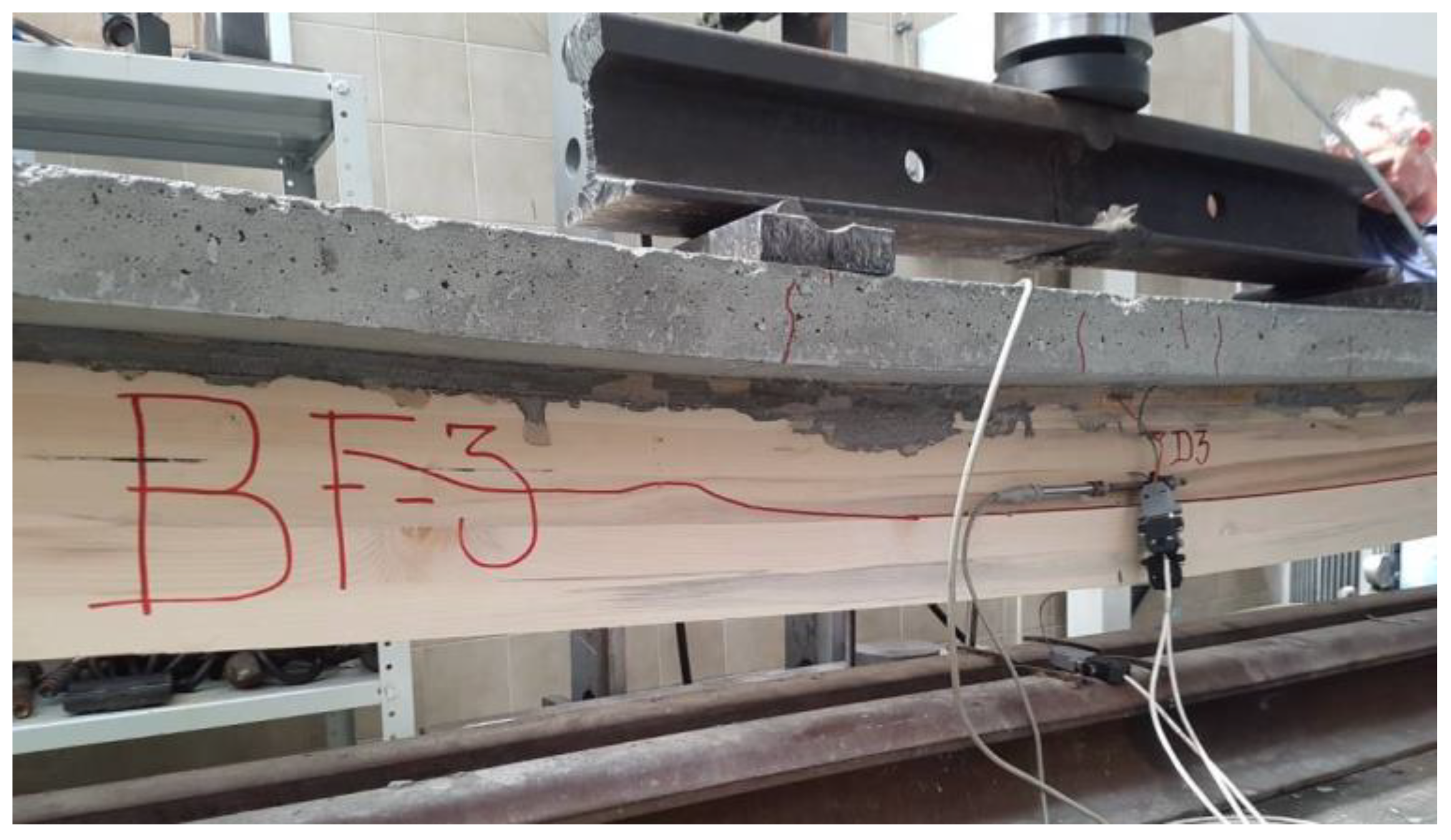
Figure 24.
Fracture of BF-3 beam, cracks development in concrete and timber parts of a composite beam.
Figure 24.
Fracture of BF-3 beam, cracks development in concrete and timber parts of a composite beam.
4.4. Failure mechanisams of B-series beams
The B-series composite beams (BN-1, BN-2, BN-3), during the loading up to the fracture showed a linear- elastic behaviour, which can be seen in the loading—deflection diagrams, shown for each composite beam separately in the Figure 16. Beams showed, when compared, a high level of similarity in their behaviours while applying the loading up to the fracture point. The variability coefficients of the achieved results related to the fracture force and the size of the elastic deformity are very low, which indicates a high quality level of the used materials of the experimental samples as well as the high quality of the experiment procedure.
Despite these facts, the fracture forms of the beams are different. In the tested BN-1 and BN-3 beams, the fracture occurred due to the initial fracture in the tensioned part of the laminated timber beam in the middle third of the span. It happened suddenly, followed by a loud and abrupt fracture of timber, which is the property of timber during tension fracture. The initial fracture occurred in the timber part with errors (knots, the plank laminating element cut irregularly so grains do not go along longitudinal direction). As the result of such an initial stress, and taking into consideration the beam span, the further fracture development is expressed in the form of a horizontal or inclined cracks line which goes towards the supports, but does not reach them (Figure 25). While creating conditions for the brittle timber fracture, due to an excessive tension strength, in the middle zone of the span of the tested beams, there was an emphasized development of cracks in the concrete slab strengthened by the concrete notches reinforced by screws. From that zone to the right and left, there is failure in the notch joint of timber and concrete and it grows bigger as it approaches the support.
In the left support of the BN-3 sample, there was a total destruction of the notch ending of the timber beam by shearing and the displacement of 12mm, which is shown in the Figure 25. The B-series beams have a much higher stiffness level compared to the A-series beams. The fracture occurs due to an excessive tension strength parallel to the grains in the timber part of the beams, and it is the stiffness of the timber-concrete joint achieved by a more complex fastening system that causes the irregular fracture which moves along the elements in the middle third of the span. After creating the necessary conditions for this fracture, the neutral line goes upwards, stresses are transferred to the timber-concrete joint zone, there is the slip of the elements of the connecting system of the B type beams, local excesses of timber shear strength and concrete tension strength in the notch zone. The consequence of this is simultaneous fracture due to an excessive timber tension strength in the middle third of the span and timber shear strength in the support notches. We must emphasize that the fracture always occurred in timber and never at the interlayer of the lamella filled with glue. This indicates that the load bearing capacity of the tested BN-1 and BN-3 beams is used completely by reaching the limit shear stress values in the support cross-sections.
BN-2 beam, with an approximately equal level of the applied loading and the reached value of the elastic deflection, shows a completely different behaviour, that is, shows a behaviour similar to the one of the tested samples of the A-series. The fracture occurred in the right support zone due to the excess of the shear stresses and the cracks develop horizontally towards the left support. In the notch joint of the timber-concrete part of the beam there is a noticeable their symmetric displacement up to the fracture point, related to the middle of the span.
Prior to the fracture in the timber part of the beam, concrete cracks in the zone of the applied loading were noticed in the thirds of the beam span. The cracks development is obvious, and the go up to the half of the height of the cross-section of the concrete part, Figure 26. In the notch zone they have perpendicular direction onto the longitudinal direction of the composite beams. None of the tested beams has any signs of plastification in the compressed zone of the concrete part of the cross-section or the compressed zone of the glued laminated timber.
Between the concrete notches and the timber notches, there are specific local stresses, there is a strong shear force, but no significant plastification if timber notch zone because of the previously caused timber shear fracture parallel to the grains.
We should emphasize that there was plastification in timber, and as in the case of the A-series, it occurs due to an excessive of timber compression strength perpendicular to the grains in the support zones of the coupled beams. Taking into consideration the shape of the cross-section of the coupled beams, a small width of the timber part of the cross-section and the length of the beam ends, supported on the specially shaped steel elements, during the loading application, step by step, before the fracture, the timber plastification of 3-5mm was noticed in the support zones.
The Figure 26, Figure 27 and Figure 28 show all B-series beams with the marked development of longitudinal, horizontal and inclined cracks in the timber part of the beams and the crack development in the middle third of the concrete slab, as well as in the concrete notch support zones.
The presentation of the experimental results for all B-series beams is given in the Table 3. In function of the maximum loading (fracture loading) the corresponding values of the forces in the characteristic cross-sections (Mmax, Tmax) are given, as well as the maximum elastic deflection and the appropriate horizontal displacement in the interlayer of the timber-concrete part of the cross-section at the fracture point. The appropriate values for the loading (Fmax), notches and horizontal displacements are taken from the experimentally achieved data bases, and the values of the bending moment at the point of fracture (Mmax) and the transversal force at the point of fracture (Tmax) are calculated according to the equation 1.
The mean loading value at the moment of fracture for the B-series beams was 84,96kN with the variation coefficient of 5,8%. A small loading difference at the fracture point of BN-i samples show a small variability of the glued laminated timber strength which was used in the composite beams. Due to a heterogeneous nature of timber, such a behaviour can be considered as unexpected in this experimental procedure, but, as already mentioned, the uniformity of samples quality can have a significant influence on the achieved results.
5. Conclusions
The following conclusions can be reached on the basis of the result obtained by testing all the A and B-series beams and their comparative analysis:
- A-series beams failed under the average loading of 80,65kN, and the B-series beam under the average loading of 84,96kN. We can conclude that the load bearing capacity of the A-series beams is lower when compared to the load bearing capacity of the B-series beams by only 5%. It means that, if we ignore the behaviour of BF-1(previously explained causes of big results dissipation), the beams of both series show almost identical performance regarding the nosivost aspect, before the first signs of their failure (different forms of fracture and major deformities);
- By comparing the maximum values of deflection in the middle of the span a double deformability of the A-series beams is defined. Their average deflection is twice as big as the deflection of the B series type under the approximately same loading and with the same geometric properties. The explanation lies in the differences of the chosen connecting systems used for the coupling of timber and concrete. The uniformity of deflection values of the B-series beams is on a higher level than in the A-series, which is a consequence of smaller structural and phenomenal changes in the timber part of the B-series beams cross-sections while applying the loading (the bigger deformities, the higher the influence of anisotropy and heterogeneity on the final results);
- The average values of the horizontal displacements, measured in the interlayer between timber and concrete in the support zones (LVDT-U4h) of the B-series samples are about six times lower than the ones in the A-series beams. This is a direct consequence of the type of the fastening system used for coupling the B-series beams, characterized by a minimum slipping, high load bearing capacity of the connecting system itself related to the maximum shear force present in this zone and an emphasized stiffness of the interlayer;
- Comparative presentation of the calculated bending stiffness values at the moment of fracture of all tested beams given in Figure 19 obviously gives advantage to the B-series of composite beams. Expressed in numbers, (figures), bending stiffness of the B-series beams is 32.85% higher than of the A-series beams. With a steady fracture loading level which characterizes the B-series beams, uniform bending stiffness values of those beams were obtained. This is prescribed to the mechanical properties of the applied connecting system which consists of screws combined with concrete notches. Its stiffness has a direct impact on the behavior of this series of the beams, on the overall bending stiffness, the deflection size and the form of the fracture (it was previously mentioned that the form of the fracture of the B-series beams due to an excessive timber shear and tension strengths is localized on the support zones and the middle third of the span, but that is not the case with the A-series beams, characterized by the final fracture due to an excessive timber shear strength parallel to the grain, in a form of a crack that continually goes along the whole length of the samples on the surface close to the neutral surface of the composite cross-section).The testing of the BF-1 beam of the A-series is an interesting one. This beam shows a 30-50% higher stiffness when compared to the stiffness of the other beams of the A-series, where the loading failure value of that beam was 20-30% lower than the loading of the other two beams. If the bending stiffness of the BF-1 beam is compared to the stiffness of the beams of the B series, we can notice that the approaching of the values at the moment of fracture, while the difference in the applied loading is about 20%. A very low increase in the applied loading is needed to reach the failure to reduce the stiffness of the BF-1 so that it is closer to the stiffness values of the BF-2 and BF-3 beams. This shows that the beams of both series up to the point of 50-60% of the loading application have a similar performance, and after that they start acting differently which is the consequence of the different mechanical properties of the used connecting systems;
- Due to numerous data which characterize the dilatation development measured at the cross-section in the middle of the span of the tested beams, as well as the above presented uniformity of dilatations on the level of certain series, Figure 21 shows a mutual presentation of the dilatation development of the BF-1 and BN-1. The dilatation development is the picture of all presented in 1), 2), 3) and 4). A better mechanical behaviour in the sense of the interconnection between the loading and the increase in the dilatations, or stress, in the B-series beams, compared to the A series can be seen in the diagrams in Figure 21. A higher level of stiffness, that is a lower deformability of the B-series beams has an impact on the stress distribution, that is the dilatation on the height of a chosen cross-section and the dilatation diagram show that clearly. For an almost identical fracture loading, the dilatation values are almost equal, but the development of dilatation in the cross-section in the middle of the span of the BN-1 is a lot more regular (linear) than in the BF-1 beam. The dilatation in the interlayer timber-concrete zone of the BN-1 series have values close to zero up to the fracture loading, which indicates a high degree of coupling, that is, a reached so-called rigid coupling. The A-series beams, regarding the measured dilatations, after just about 30% of the fracture loading, show differences in the intensity which shows that it is an elastic coupling because of the deformability of the connecting systems and displacements in the interlayer of timber and concrete;
- Related to the shear stress state in the support zones, based on the diagrams from Figure 20 which shows the relationship between loading-shear stress, in the function of the measured and calculated main dilatation ε1 and ε2, we can conclude that the value of the shear stress in the B-series beams ranges from 10-20 N/mm2. And in the A-series beams, the range is from 15-35 N/mm2. The non-linear development of the function of relation F-τ shoes an irregular and non-uniform fracture due to an excessive timber shear strength parallel to the grains, that is in the surfaces with a dominant dilatation development ε1. Thanks to a higher level of bending stiffness of the B-series beams, the dilatation is lower, and thus, a lower level of achieved shear stress state level in the supports.
References
- Cvetković, R. Behaviour of Composite Timber-Concrete Structures with Bending Actions. Master thesis, Ruhr University Bochum, Germany, 2002.
- Stevanović B. Analysis of Composite Timber-Concrete Structures, Ph.D. thesis, University of Belgrade, Serbia, 2003.
- Cvetković, R.; Stojić, D.; Marković, N.; Trajković, M.; Živković, D. Repair and Strengthening of Timber Floors of Pančevo Diocese by Timber–Concrete CouplingTechnique. Journal Tehnički vjesnik/Technical Gazette (Print: ISSN 1330-3651, Online: ISSN 1848-6339), 2018, Vol. 26/No. 4.
- Maslak, E.; Stojić, D.; Drenić, D.; Mešić, E.; Cvetković, R. Ojačanje spregnutih nosača drvo-beton prednapetom armaturom. Građevinar. 2020, Vol. 72/11, pages 1-10.
- Dias, A. M. P. G.: Mechanical behaviour of timber-concrete joints. Ph.D. thesis, University of Coimbra, Portugal, 2005.
- Clouston, P.; Bathon, L.; Schreyer, A. Shear and bending performance of a novel wood-concrete composite system, Journal of Structural Engineering 2005, 131(9), 1404–1412. [CrossRef]
- Ceccotti, A.; Fragiacomo, M.; Giordano, S. Long-term and collapse tests on a timber-concrete composite beam with glued-in connection, Material and Structures. 2006, 40(1), 15–25. [CrossRef]
- Deam, B. L.; Fragiacomo, M.; Gross, L. S. Experimental behavior of prestressed LVL-concrete composite beams, Journal of Structural Engineering. 2008, 134(5), 801–809. [CrossRef]
- Gutkowski R.; Brown K.; Shigidi A.; Natterer J. Investigation of notched composite wood concrete connections. ASCE Journal of Structural Engineering. 2004, 130(10), 1553-1561. [CrossRef]
- Balogh, J.; Fragiacomo, M.; Gutkowski, R. M.; Fast, R. S. Influence of repeated and sustained loading on the performance of layered wood-concrete composite beams. Journal of Structural Engineering. 2008, 134(3), 430–439. [CrossRef]
- Balogh, Z.; Gutkowski, R. Modelling of shear transfer in wood-concrete notch connections. In Proceedings of the 10th World Conference on Timber Engineering, Miyazaki, Japan, 2-5 June 2008.
- Fragiacomo, M.; Gutkowski, R.; Balogh, J. and Fast, R. Long-term behaviour of wood-concrete composite floor/deck systems with shear key connection detail. Journal of Structural Engineering. 2007, 133(9), 1307–1315. [CrossRef]
- Gutkowski, R.; Brown, K.; Shigidi, A.; Natterer, J. Laboratory tests of composite wood-concrete beams, Constr. Build. Mater. 2008, 22(6), 1059–1066. [CrossRef]
- Balogh J.; Fragiacomo M.; Miller N.; Gutkowski R.; Atadero R.; To L. Testing of Wood-Concrete Composite Beams with Shear Key Detail, In Proceedings of International Conference on Timber Bridges, Lillehammer, Norway.; September 2010.
- Lukaszewska E. Development of prefabricated timber-concrete composite floors. PhD thesis, Luleå University of Technology, Sweden, 2009.
- Lukaszewska E.; Johnsson H. Connections for prefabricated Timber-Concrete composite systems. In Proceedings of the 9th World Conference on Timber Engineering, Portland, USA, 6-10 August 2006.
- Lukaszewska, E.; Fragiacomo M. Static performance of prefabricated timber-concrete composite systems. In Proceedings of the 10th World Conference on Timber Engineering, Miyazaki, Japan, 2-5 June 2008.
- Lukaszewska, E., Fragiacomo, M., Johnsson, H.:, Laboratory tests and numerical analyses of prefabricated timber-concrete composite floors. Journal of Structural Engineering. 2010, 136(1), 46–55. [CrossRef]
- Lukaszewska E.; Johnsson H.; Fragiacomo M. Performance of connections for prefabricated timber-concrete composite floors. Material and Structures. 2008, 41(9), 1533–1550. [CrossRef]
- Yeoh, D. Behaviour and design of timber-concrete composite floor system, Ph.D. thesis, University of Canterbury, New Zealand, 2010.
- Yeoh D.; Fragiacomo M.; De Franceschi M.; Buchanan A. Experimental tests of notched and plate connectors for LVL-concrete composite beams. Journal of Structural Engineering. 2001, 137(2), 261–269. [CrossRef]
- Eurocode 2: EN 1992-1-1 Eurocode 2: Design of concrete structures-Part 1-1- General rules and rules for buildings. CEN-European Committee for Standardization, 2004.
- Evrokod 4 -Proračun spregnutih konstrukcija od čelika i betona- Deo 1-1: Opšta pravila i pravila za zgrade, EN 1994-1-1:2004, Beograd, 2006.
- Evrokod 5-Proračun drvenih konstrukcija-Deo 1-1: Opšta pravila i pravila za zgrade, EN 1995-1-1:2004, Beograd, 2009.
- Stevanović, B. Eksperimentalna i teorijska analiza spregnutih nosača drvo-beton izve¬denih mehaničkim spojnim sredstvima, Materijali i konstrukcije, 2004, Vol. 47, No. 1-2, pp. 29-46.
- Cvetković, R. Mehaničko ponašanje spregnutih konstrukcija tipa drvo-beton (Mechanical behaviour of composite structures type timber-concrete). Ph.D. thesis, University of Niš, Serbia, 2017.
Figure 1.
Strengthening of the existing timber floor structures of the object with a cultural monument status, using the method of coupling with concrete. (Serbia, R. Cvetkovic).
Figure 1.
Strengthening of the existing timber floor structures of the object with a cultural monument status, using the method of coupling with concrete. (Serbia, R. Cvetkovic).
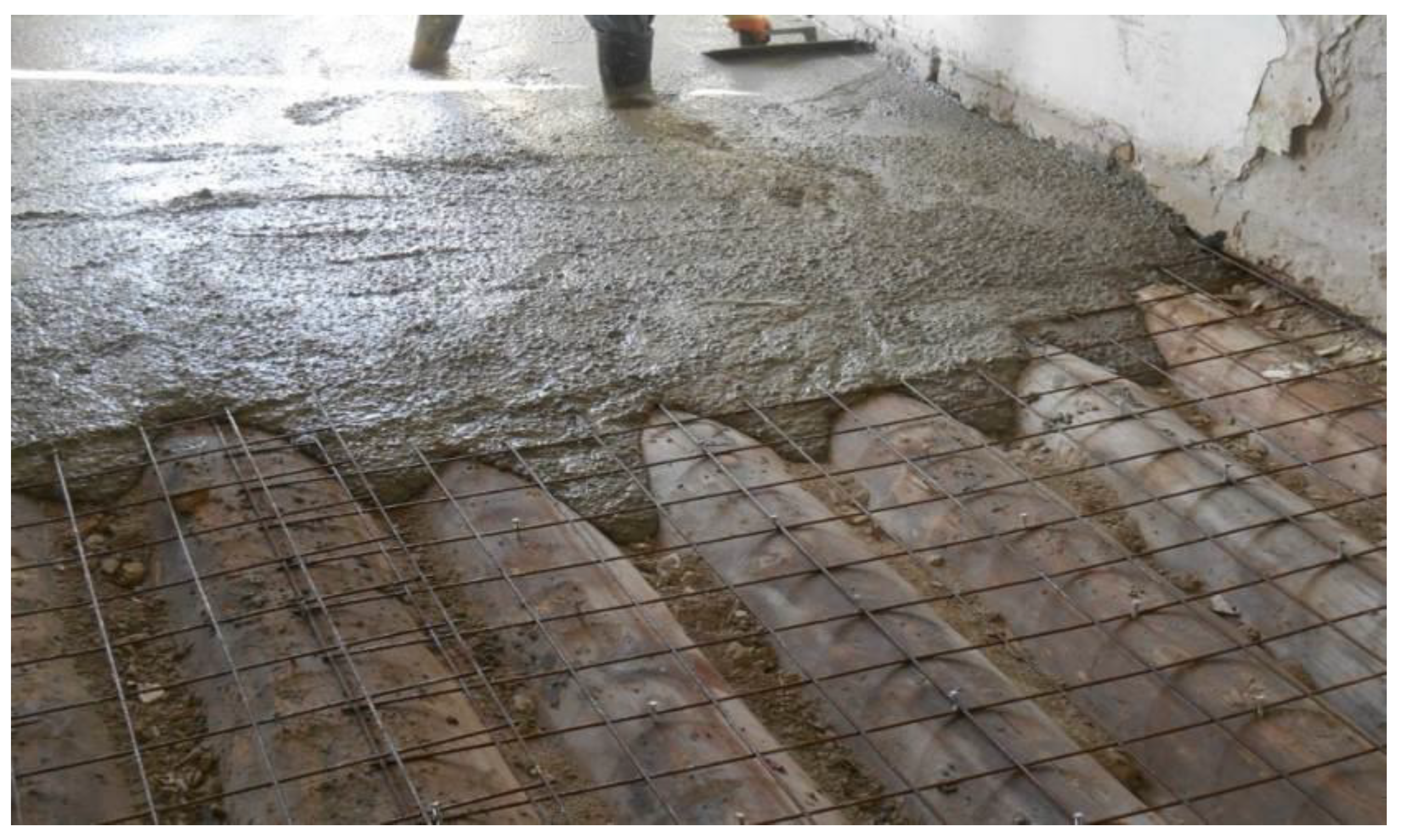
Figure 2.
Cross section of a composite beam of timber-concrete type (Ceccotti, 2006).
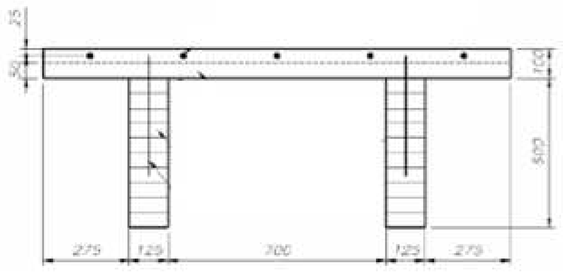
Figure 4.
Composite beam of timber-concrete type with notches and screws.
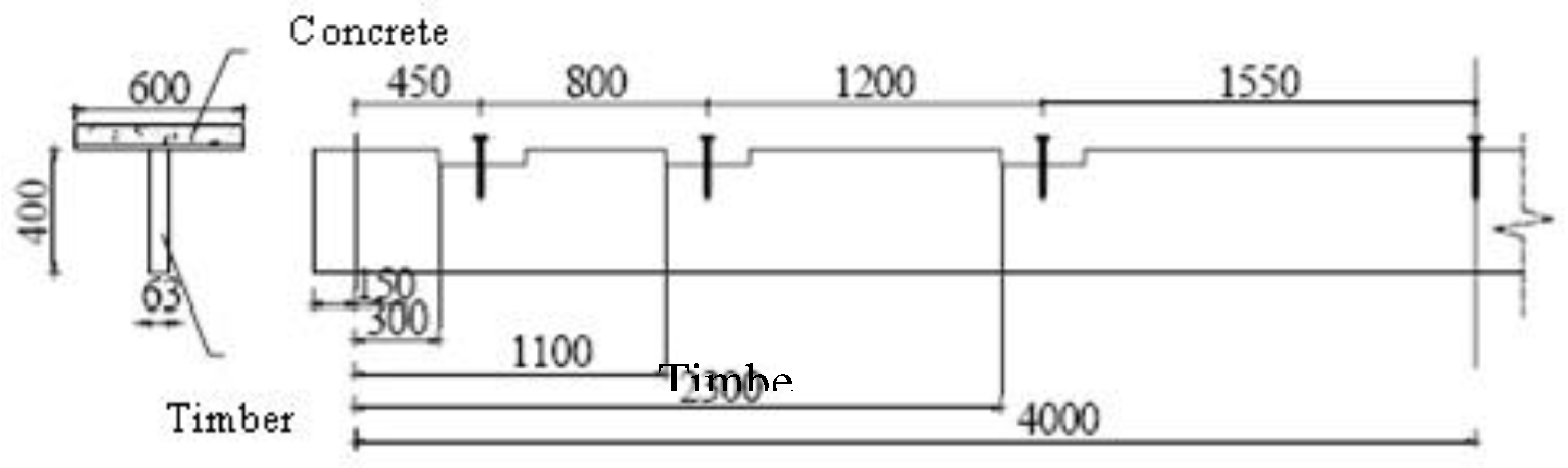
Figure 5.
(a) System of coupling of A-series beams; (b) Screws positioned at 150mm distance.
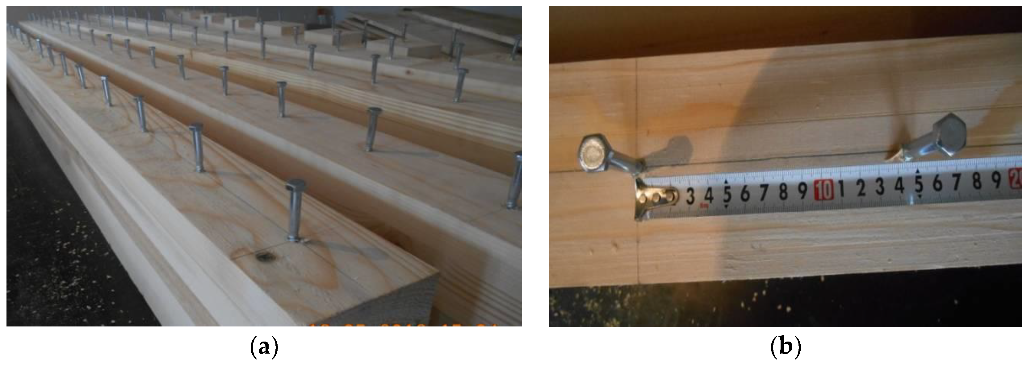
Figure 6.
(a) System of coupling of B-series beams; (b) Screw + notch reinforced by a screw.
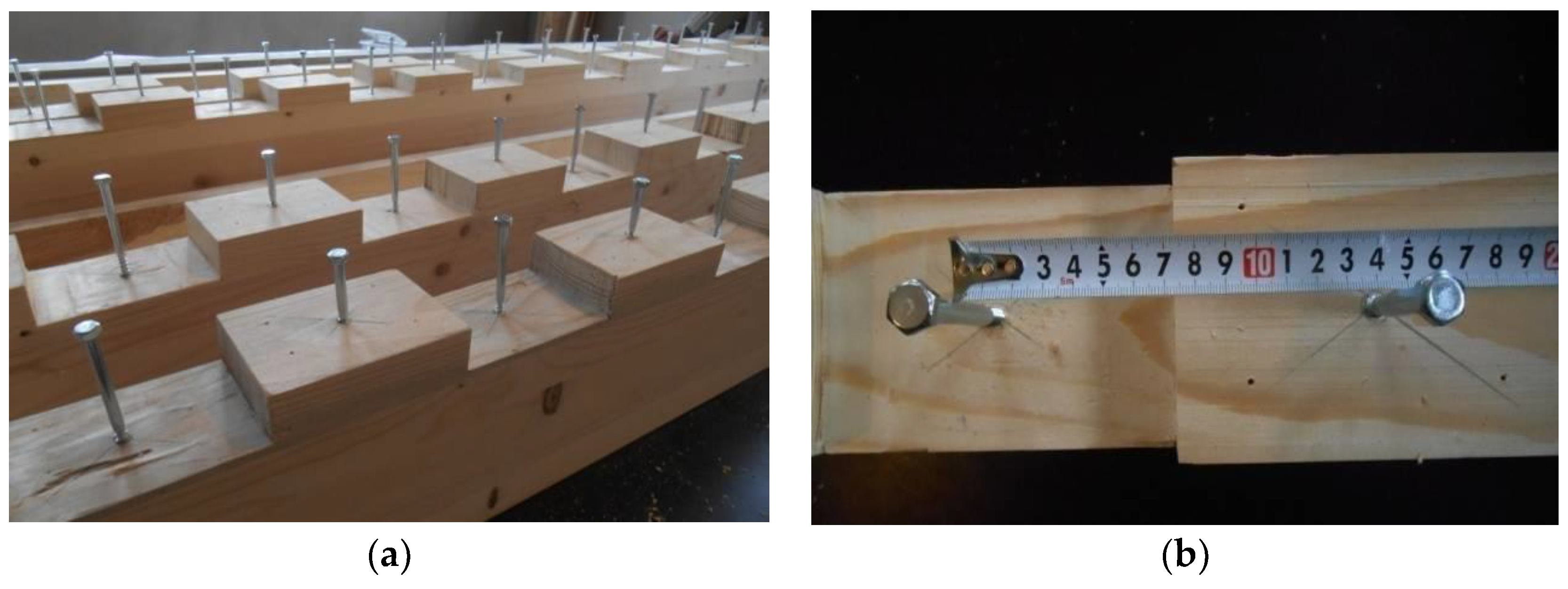
Figure 7.
(a) Moisture protection of samples; (b) Platform for creating formwork of composite timber-concrete beams, series A and B.
Figure 7.
(a) Moisture protection of samples; (b) Platform for creating formwork of composite timber-concrete beams, series A and B.
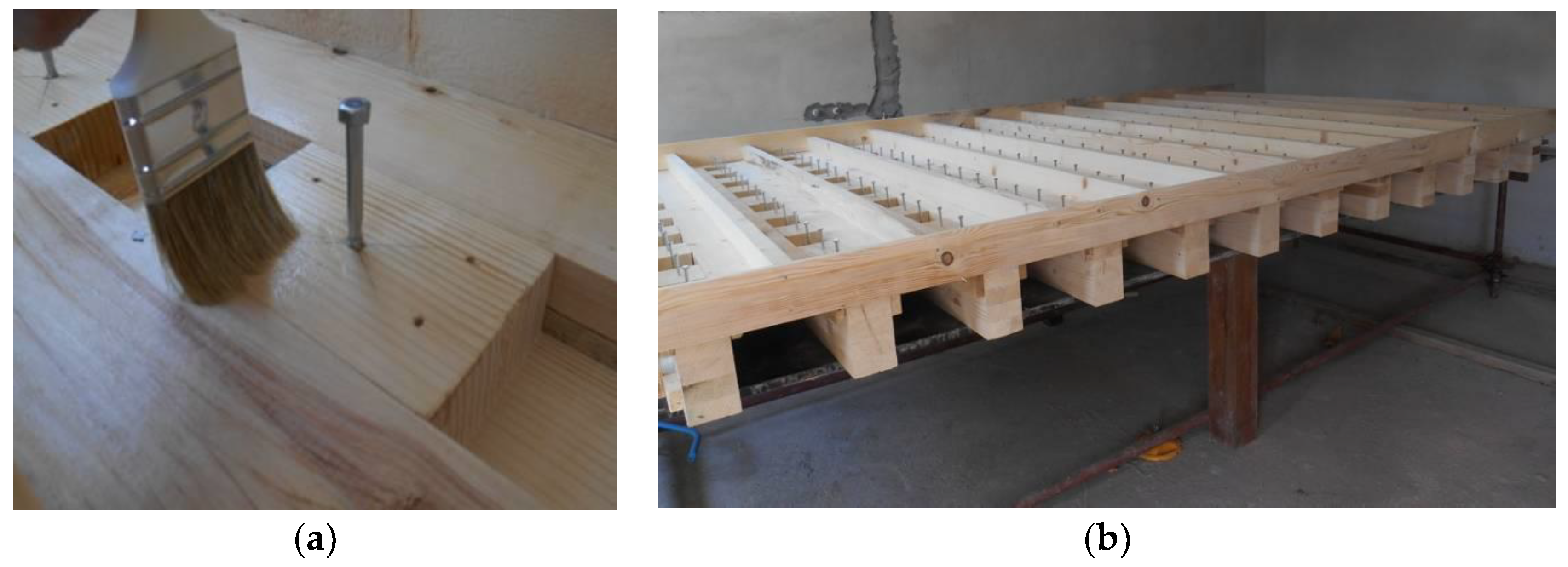
Figure 8.
Formwork of composite timber-concrete beams before casting concrete.
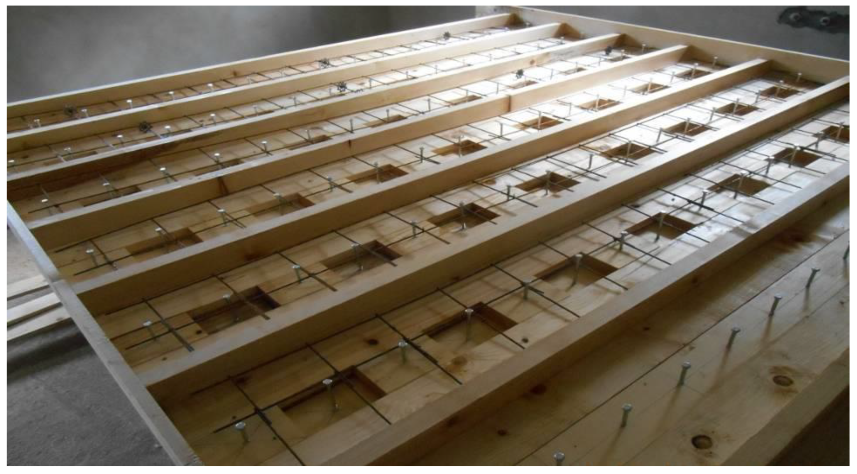
Figure 9.
(a) Pervibrator usage; (b) Distanced steel mesh; (c) Concrete application.
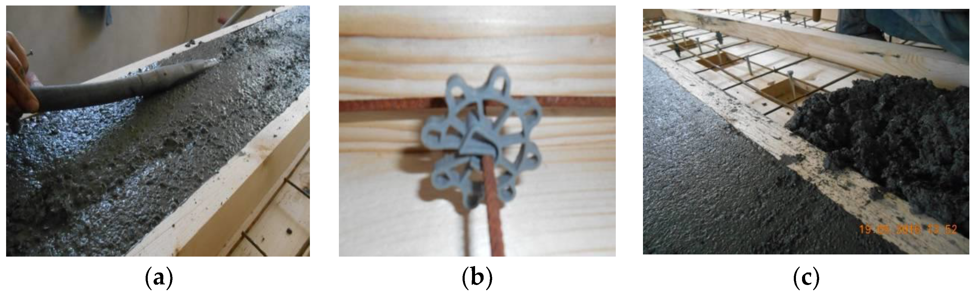
Figure 10.
(a) Geometric characteristics of composite beams A-series; b) Geometric characteristics of composite beams B-series B type and the positioning of fasteners and notches.
Figure 10.
(a) Geometric characteristics of composite beams A-series; b) Geometric characteristics of composite beams B-series B type and the positioning of fasteners and notches.
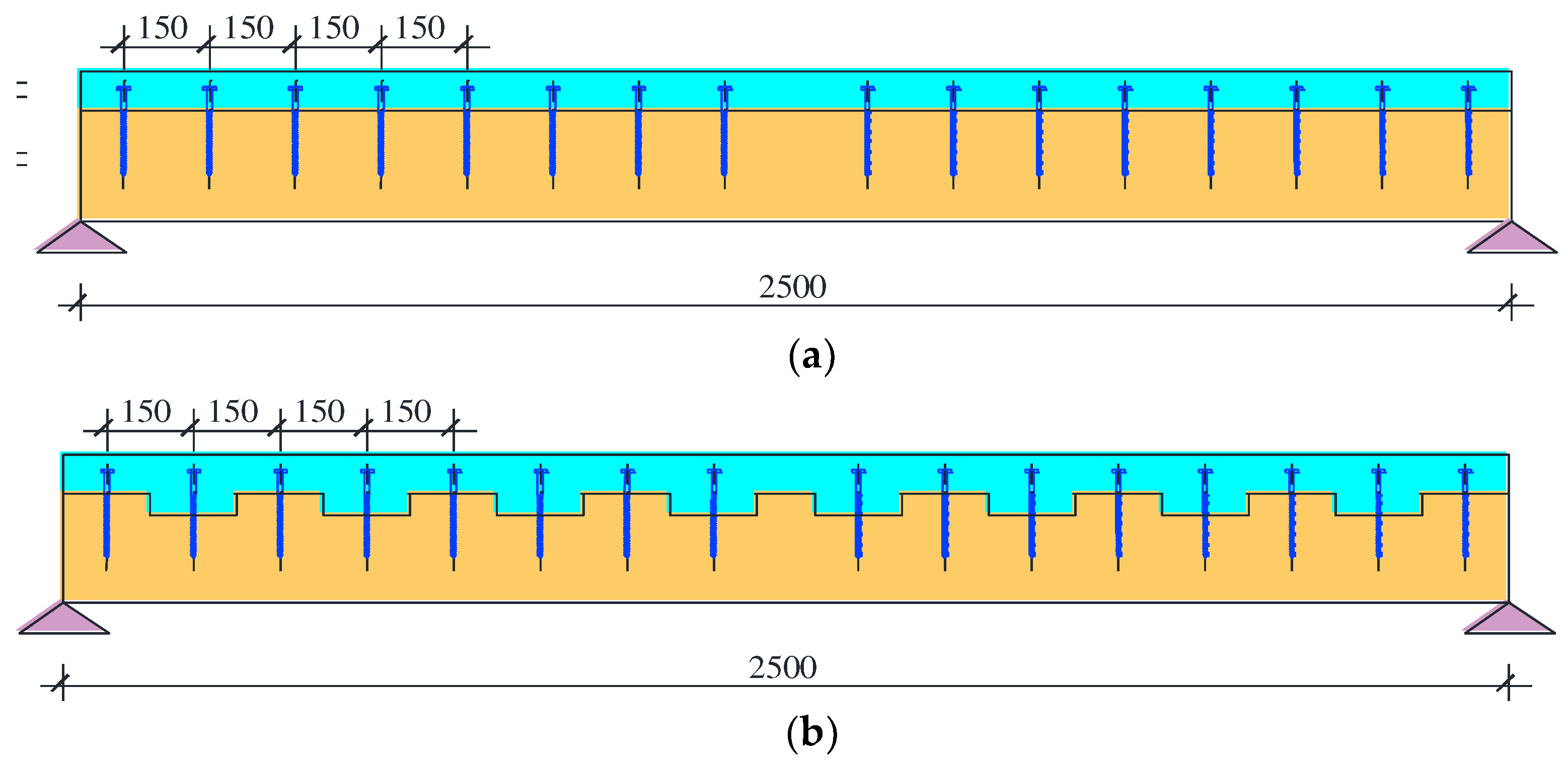
Figure 11.
Eksperiment setup of composite beams B-series.
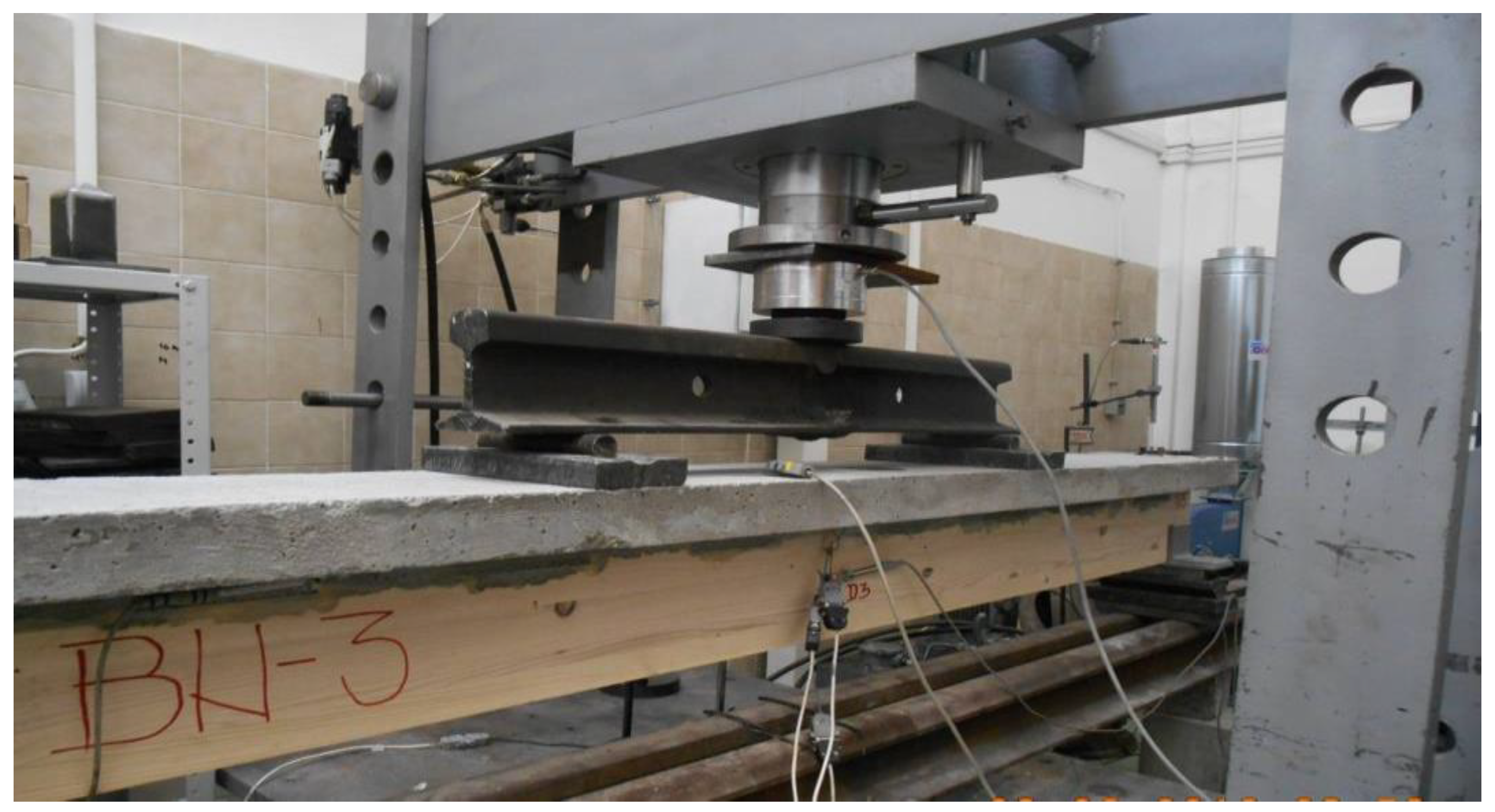
Figure 12.
(a) Position of rosettes and strain gauages in the zone of support; (b) Position of strain gauages in the middle beam zone in the upper timber fibre and lower concrete fibre.
Figure 12.
(a) Position of rosettes and strain gauages in the zone of support; (b) Position of strain gauages in the middle beam zone in the upper timber fibre and lower concrete fibre.
Figure 13.
(a) Dilatometer position in the support zone; (b) Dilatometer pos. in the middle beam zone.
Figure 13.
(a) Dilatometer position in the support zone; (b) Dilatometer pos. in the middle beam zone.
Figure 14.
Model of a composite beam of BF type. Loading disposition, the location of measuring points.
Figure 14.
Model of a composite beam of BF type. Loading disposition, the location of measuring points.
Figure 15.
Model of composite beam of the B-series, BN type, loading dispositions, measuring points position.
Figure 15.
Model of composite beam of the B-series, BN type, loading dispositions, measuring points position.
Figure 16.
Comparative presentation of the relationships of F-u of all tested beams.
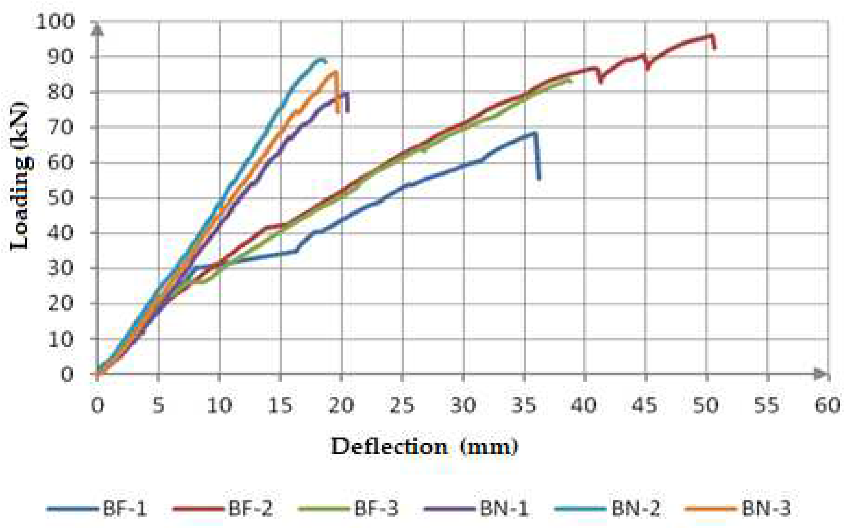
Figure 17.
Comparative presentation of deflection values at the fracture point of all tested beams.
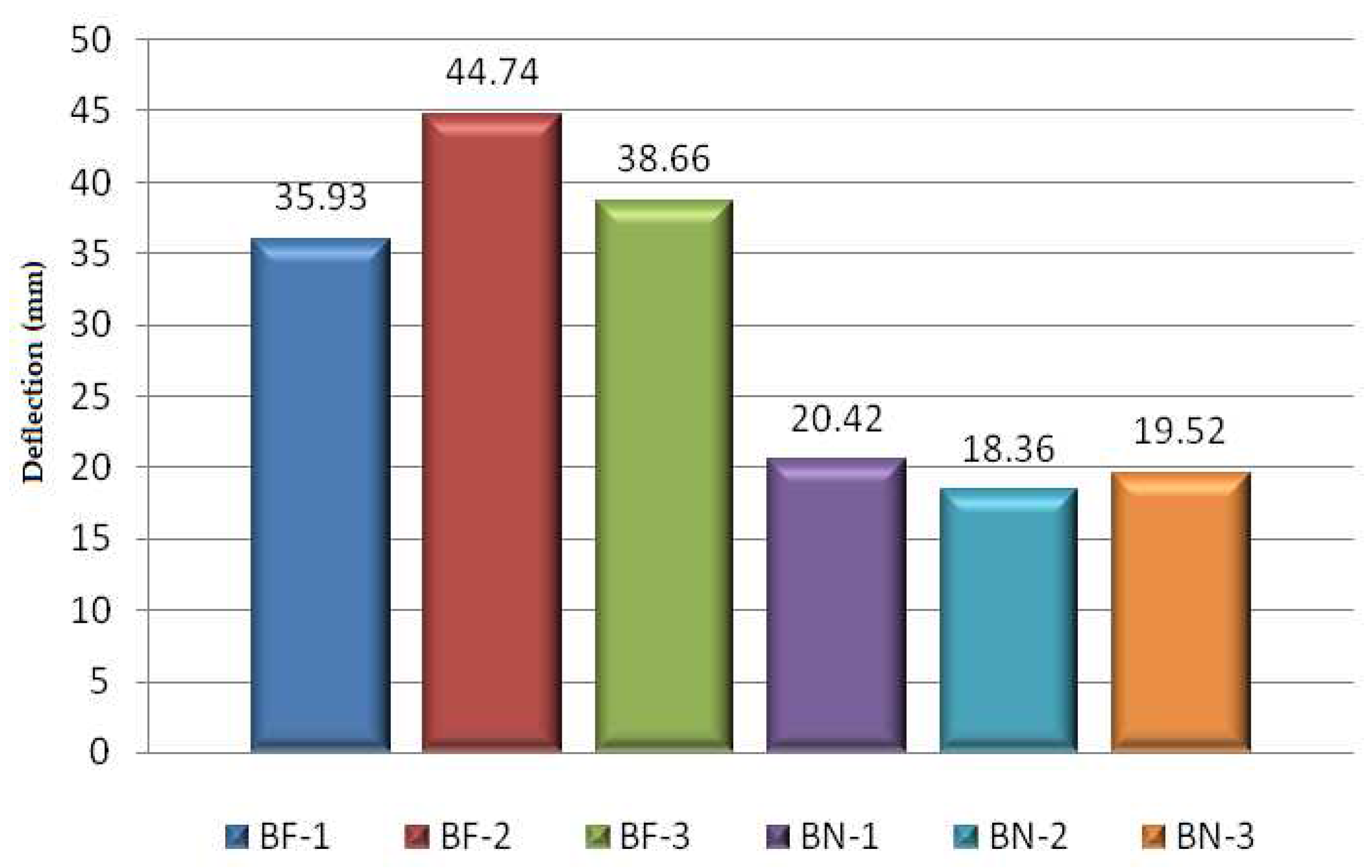
Figure 18.
Comparative presentation of loading values at the fracture point of all tested beams.
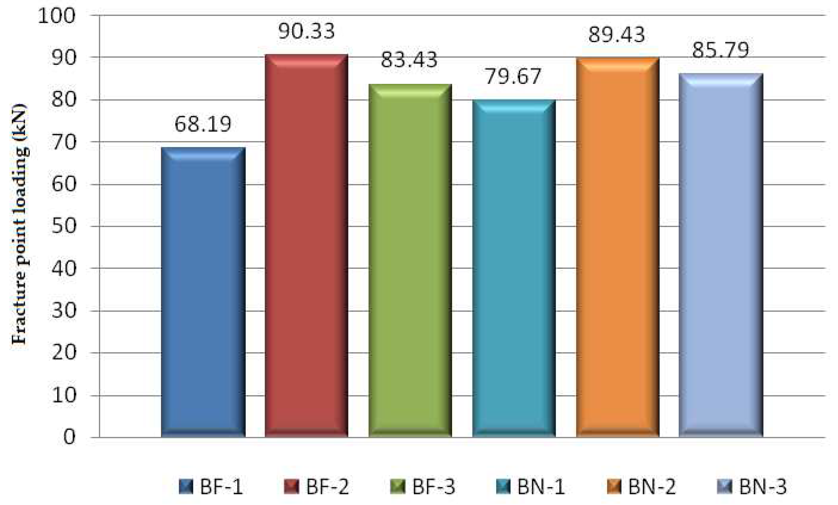
Figure 19.
Comparative presentation of calculated values of bending stiffness (EI) at the fracture point of all tested beams.Figure 19. gives a comparative presentation of the calculated values of bending stiffness at the moment of fracture of all tested beams marked as BF-1…BN-3
Figure 19.
Comparative presentation of calculated values of bending stiffness (EI) at the fracture point of all tested beams.Figure 19. gives a comparative presentation of the calculated values of bending stiffness at the moment of fracture of all tested beams marked as BF-1…BN-3
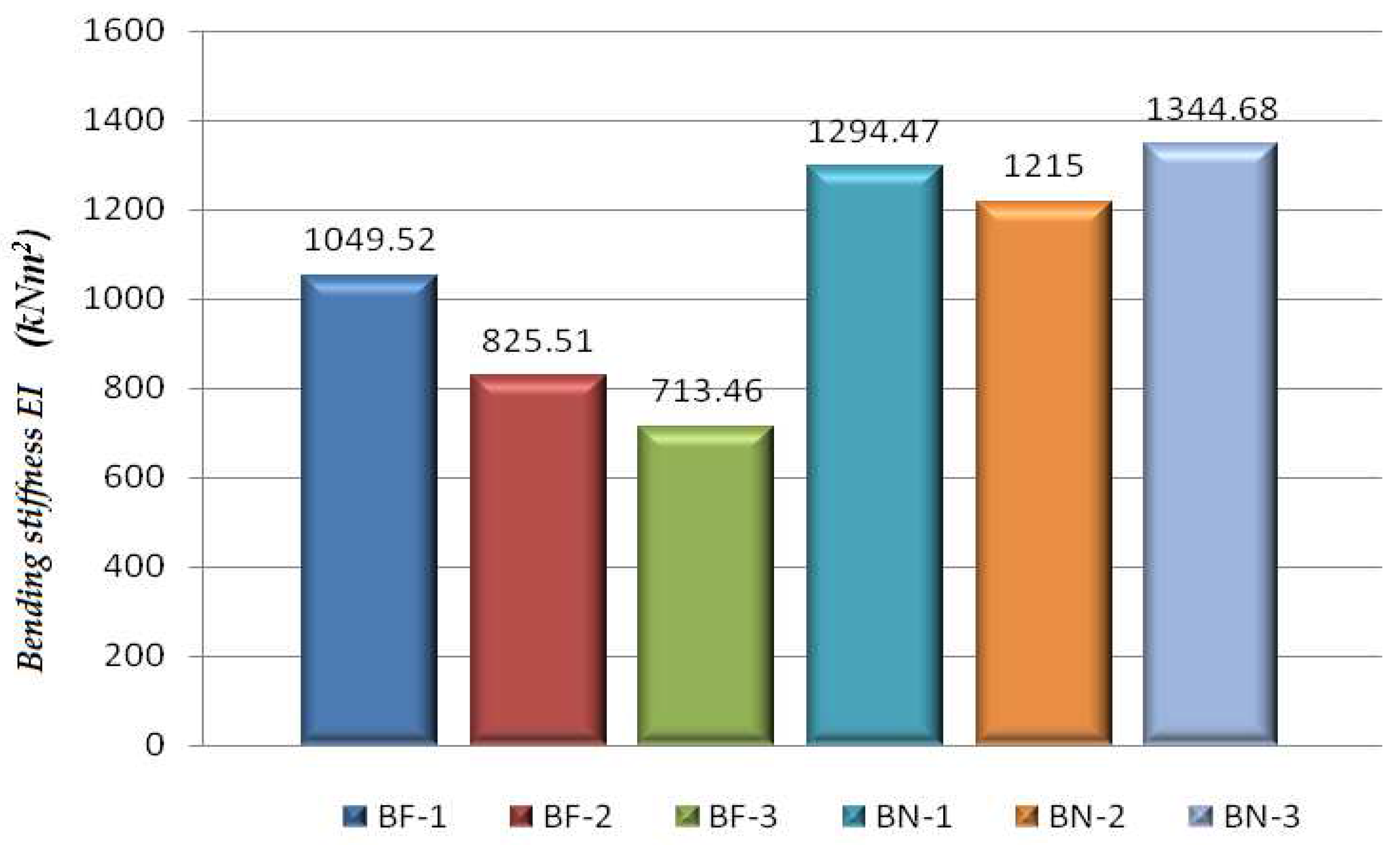
Figure 20.
Comparative presentation of F- τ relation of the tested beams.
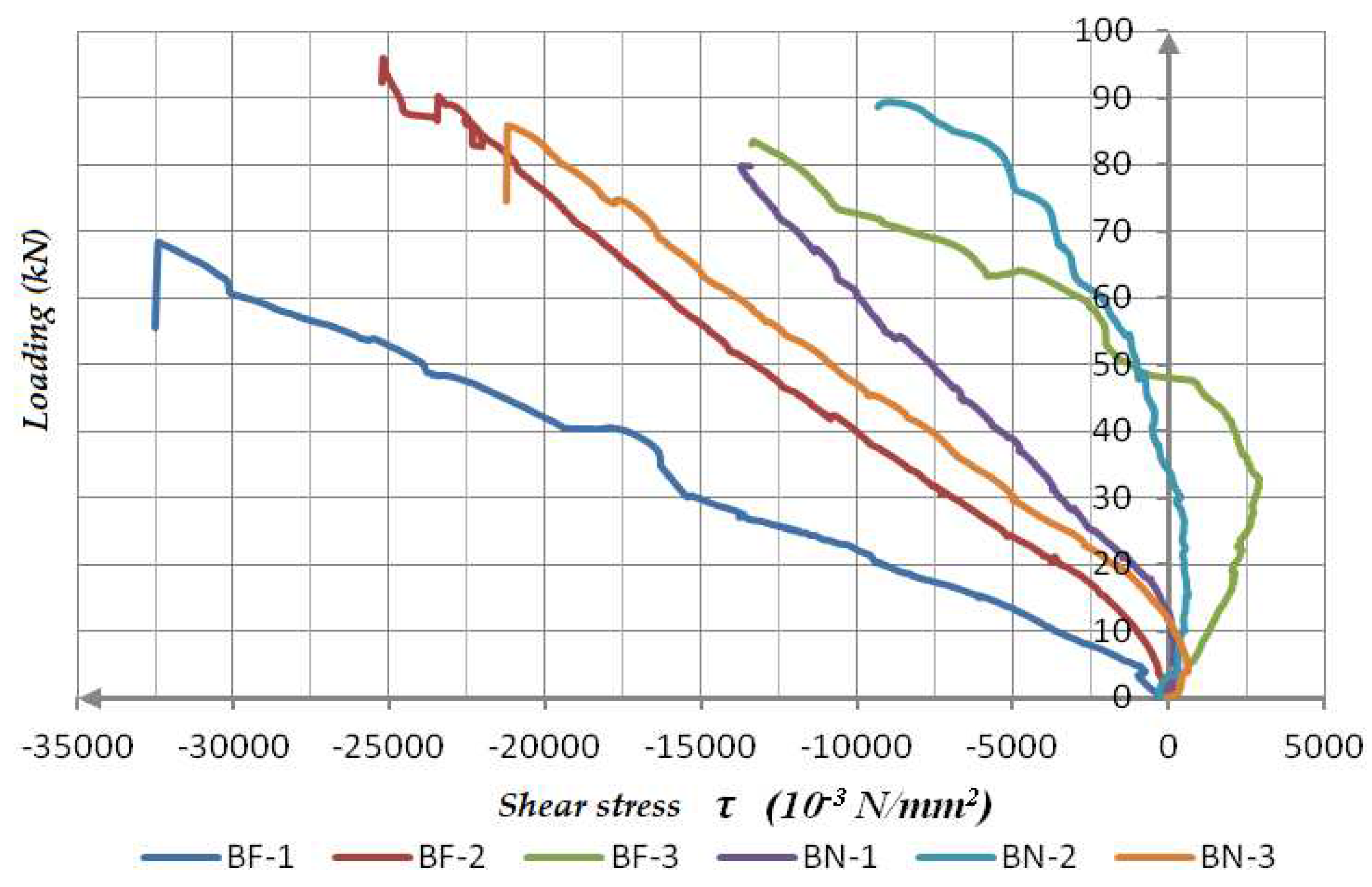
Figure 21.
Comparative presentation of measured dilatations of BF-1 and BN-1 beams.
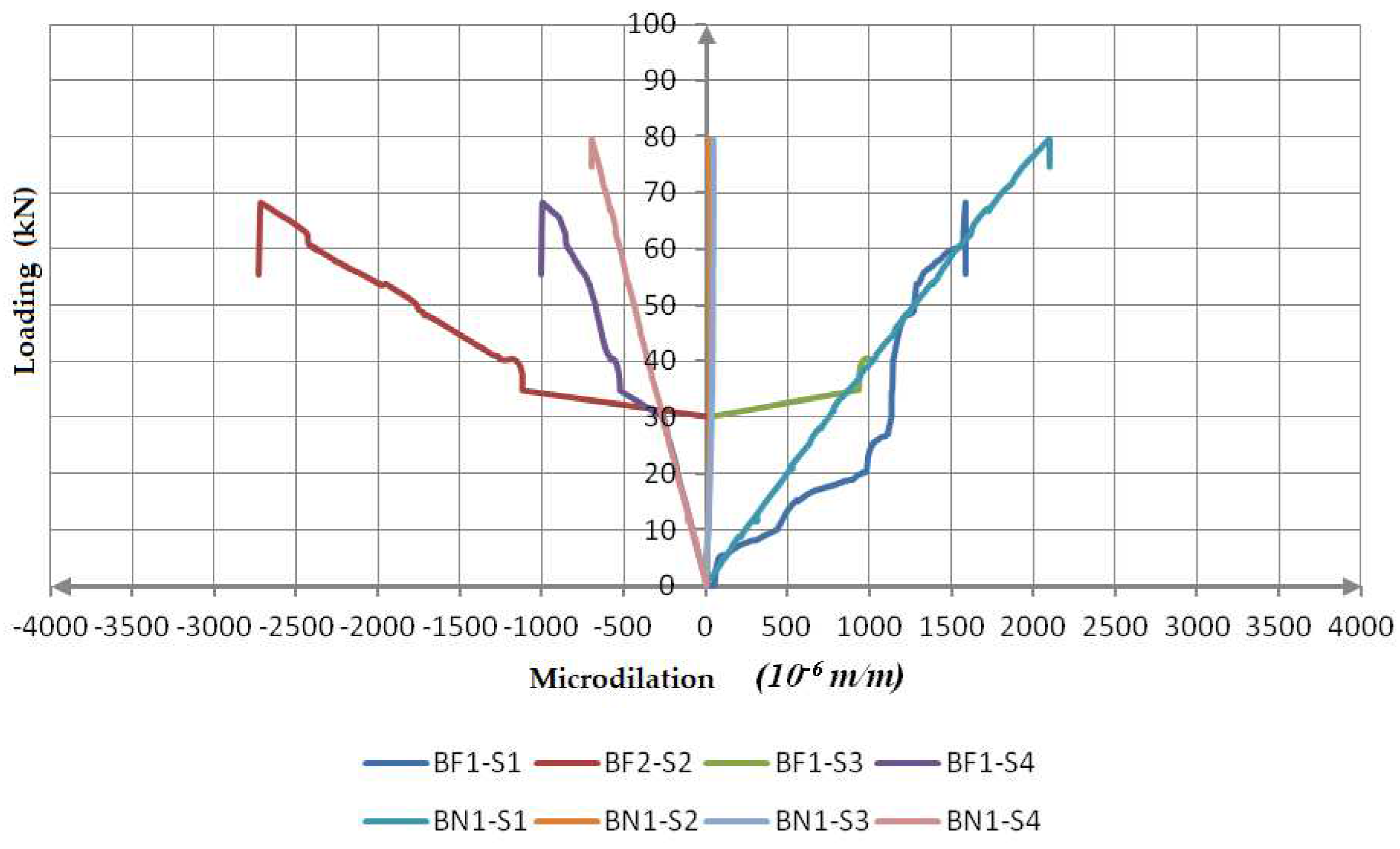
Figure 22.
Fracture of BF-1 beam, cracks development in concrete and timber parts of a composite beam.
Figure 22.
Fracture of BF-1 beam, cracks development in concrete and timber parts of a composite beam.
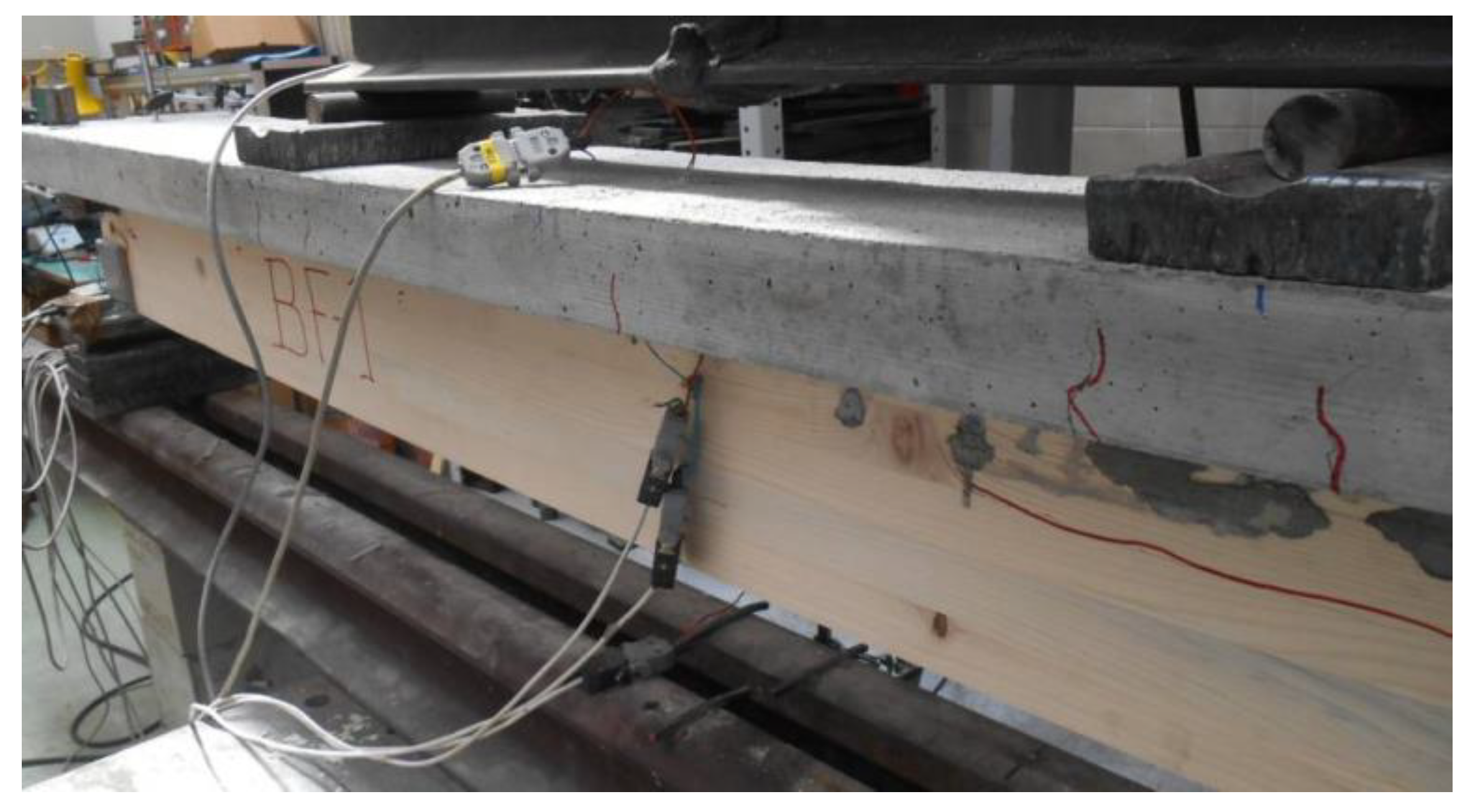
Figure 23.
Fracture of BF-2 beam, cracks development in concrete and timber parts of a composite beam.
Figure 23.
Fracture of BF-2 beam, cracks development in concrete and timber parts of a composite beam.
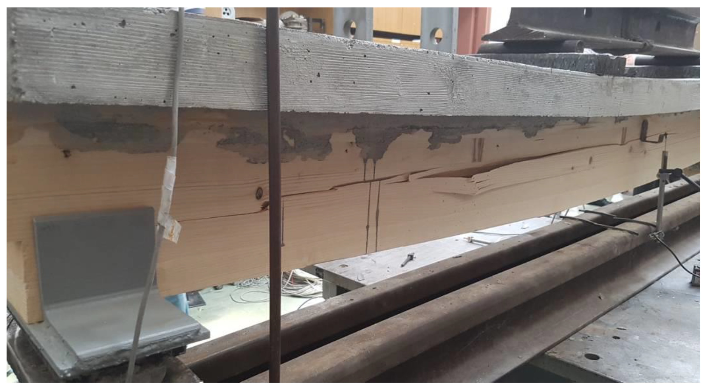
Figure 25.
(a) Fracture of the timber part of the support notch of BN-3 beam; (b) Crack development in concrete and timber fracture in the middle third of the span.
Figure 25.
(a) Fracture of the timber part of the support notch of BN-3 beam; (b) Crack development in concrete and timber fracture in the middle third of the span.
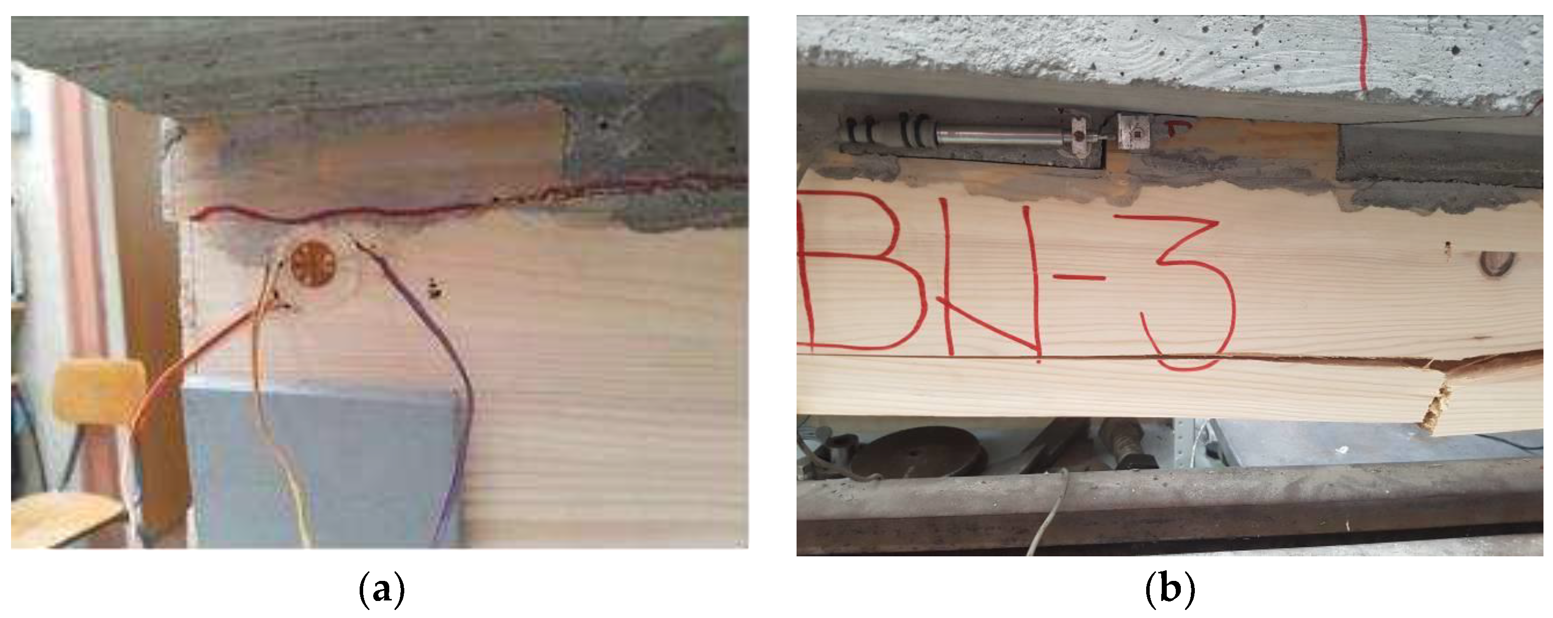
Figure 26.
Fracture of BN-1 beam, cracks development in concrete and timber.
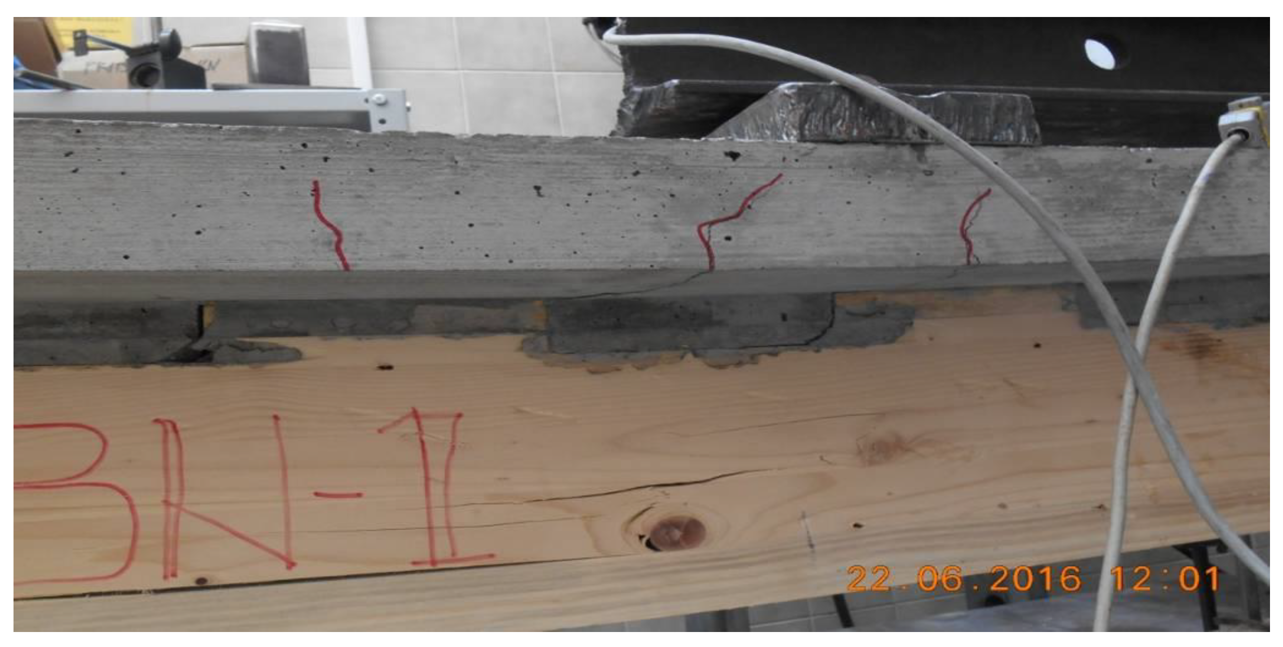
Figure 27.
Fracture of BN-2 beam, cracks development in concrete and timber.
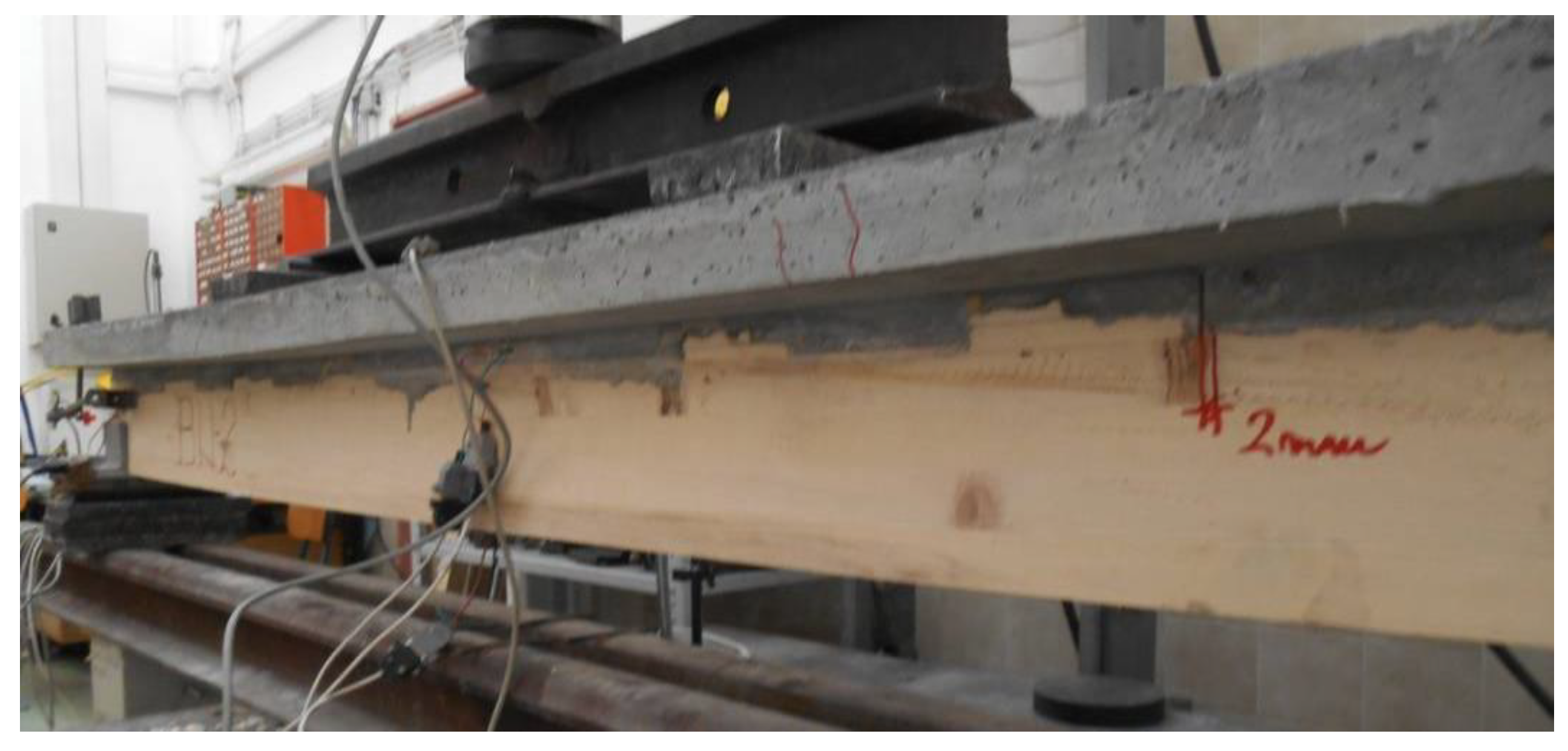
Figure 28.
Fracture of BN-3 beam, cracks development in concrete and timber.
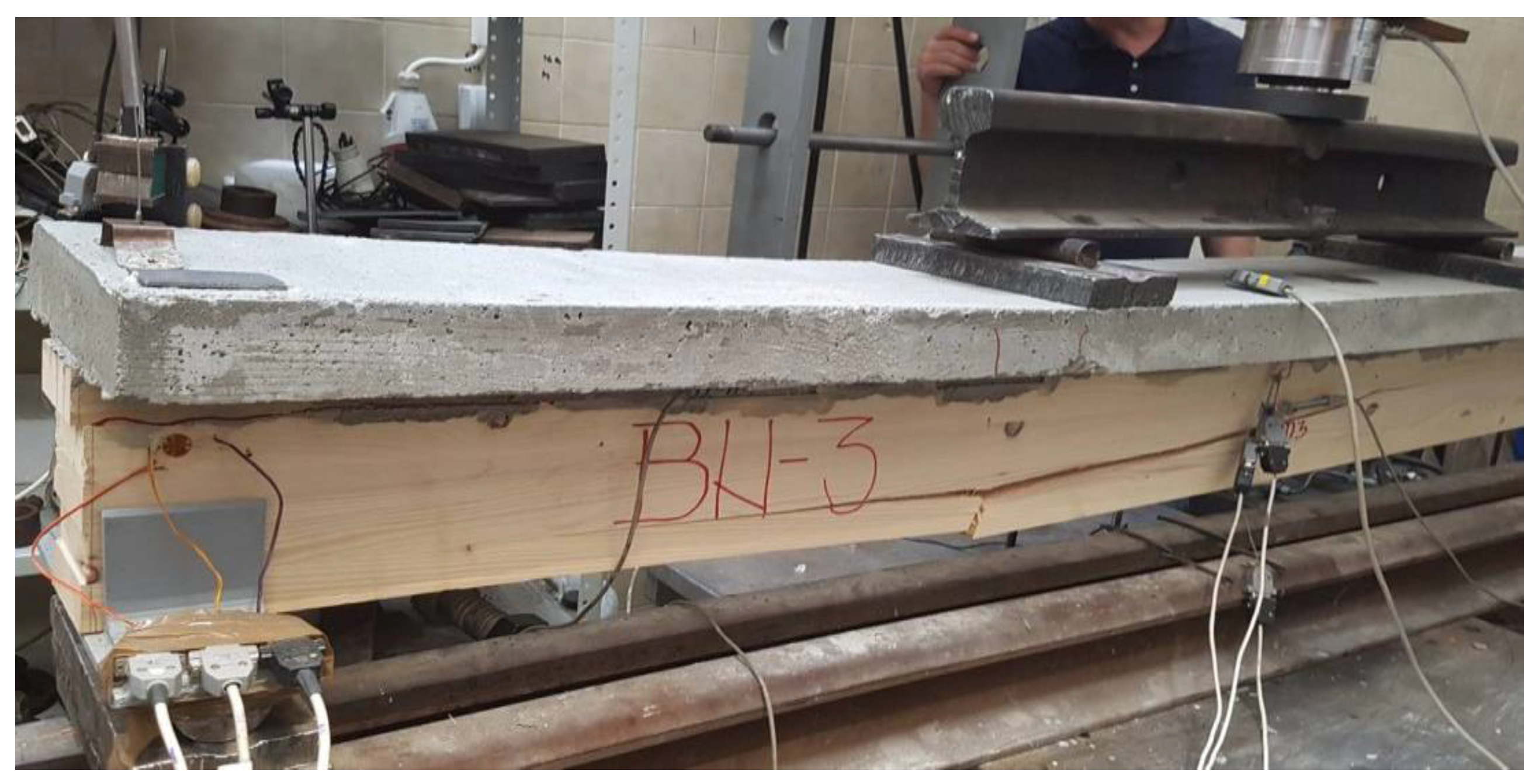

Table 1.
Location and description of measuring points for BF-i beams.
| Beams BF-1, BF-2, BF-3 | ||
|---|---|---|
| Measuring point | Description of measuring point | Measurement quantity |
| S1 | Timber lower (the middle of a beam span) | Dilatation |
| S2 | Timber upper (the middle of a beam span) | Dilatation |
| S3 | Concrete lower (the middle of a beam span) | Dilatation |
| S4 | Concrete upper (the middle of a beam span) | Dilatation |
| S0 | Left support | Dilatation |
| S120 | Left support | Dilatation |
| S -120 | Left support | Dilatation |
| U1 | Deflection in the middle of a span | Displacement |
| U2 | Vertical displacement of a left support | Displacement |
| U3 | Vertical displacement of a right support | Displacement |
| U5h | Horizontal displacement in timber-concrete interlayer-right support |
Displacement |
| U5h- D3 | The middle of the cross-sectional height of the timber part (BF 2-base 100mm) | Dilatation |
| DIN | Dinamometer | Force |
Table 2.
Positioning and description of measuring points for BN-i beams.
| Beams BN-1, BN-2, BN-3 | ||
|---|---|---|
| Measuring point | Description of measuring point | Measurement quantity |
| S1 | Timber lower (the middle of a beam span) | Dilatation |
| S2 | Timber upper (the middle of a beam span) | Dilatation |
| S3 | Concrete lower (the middle of a beam span) | Dilatation |
| S4 | Concrete upper (the middle of a beam span) | Dilatation |
| So | Left support | Dilatation |
| S120 | Left support | Dilatation |
| S-120 | Left support | Dilatation |
| U1 | Deflection in the middle of a span | Displacement |
| U2 | Vertical displacement of a left support | Displacement |
| U3 | Vertical displacement of a right support | Displacement |
| U4h | Horizontal displacement in timber-concrete interlayer-left support |
Displacement |
| U5h | Horizontal displacement in timber-concrete interlayer-right support |
Displacement |
| U4h- D2 | Horizontal displacement in timber-concrete interlayer-left support—(2. notch from the left of zhe BN3) |
Displacement |
| U5h- D3 | Sredina visine preseka drvenog dela(BN 3-baza 25mm) | Dilatation |
| DIN | Dinamometer | Force |
Table 3.
Results of the experimental testing of the A and B-series of composite beams.
| Sample | Fmax [kN] |
Mmax [kNm] |
Tmax [kN] |
U1max [mm] |
U4h [mm] |
U5h-D3 [mm] |
EI [kNm2] |
|---|---|---|---|---|---|---|---|
| BF-1 | 68,19 | 28,41 | 85,23 | 35,93 | 4,27 | 0,01 | 1049,52 |
| BF-2 | 90,33 | 37,63 | 112,91 | 44,74 | 4,095 | 0,05 | 825,51 |
| BF-3 | 83,43 | 34,76 | 104,28 | 38,66 | 4,095 | 0,002 | 713,46 |
| BN-1 | 79,67 | 33,19 | 99,58 | 20,42 | 0,75 | 0,018 | 1294,47 |
| BN-2 | 89,43 | 37,26 | 111,79 | 18,36 | 0,76 | 0,020 | 1215,94 |
| BN-3 | 85,79 | 35,74 | 107,23 | 19,52 | 0,63 | 0,023 | 1344,68 |
| Mean values, BF-i | 80,65 | 33,60 | 100,81 | 39,78 | 4,15 | 0,0207 | 862,83 |
| Mean values, BN-i | 84,96 | 35,40 | 106,20 | 19,43 | 0,713 | 0,0203 | 1285,03 |
| Statistical analysis of series results BF-i | |||||||
| Stan. deviation | 11,33 | 4,72 | 14,16 | 4,51 | 0,10 | 0,0257 | 141,11 |
| Characterist. values | 42,45 | 17,69 | 53,05 | 24,57 | 3,81 | -0,066 | 285,89 |
| Coeff.var. (%) | 14,0 | 14,0 | 14,0 | 11,3 | 2,4 | 1,244 | 19,8 |
| Statistical analysis of series results BN-i | |||||||
| Stan. deviation | 4,93 | 2,06 | 6,17 | 1,03 | 0,072 | 0,0025 | 64,89 |
| Characterist. values | 68,33 | 28,46 | 85,40 | 15,95 | 0,469 | 0,0118 | 1066,25 |
| Coeff. var. (%) | 5,8 | 5,8 | 5,8 | 5,3 | 10,1 | 12,4 | 5,0 |
Disclaimer/Publisher’s Note: The statements, opinions and data contained in all publications are solely those of the individual author(s) and contributor(s) and not of MDPI and/or the editor(s). MDPI and/or the editor(s) disclaim responsibility for any injury to people or property resulting from any ideas, methods, instructions or products referred to in the content. |
© 2023 by the authors. Licensee MDPI, Basel, Switzerland. This article is an open access article distributed under the terms and conditions of the Creative Commons Attribution (CC BY) license (https://creativecommons.org/licenses/by/4.0/).
Copyright: This open access article is published under a Creative Commons CC BY 4.0 license, which permit the free download, distribution, and reuse, provided that the author and preprint are cited in any reuse.


