
Submitted:
26 July 2024
Posted:
30 July 2024
You are already at the latest version
Abstract
This study addresses the enhancement of material efficiency and reduction of brittleness in timber-to-concrete adhesive connections for beam-type timber and timber-concrete composite panels. The research explores the potential benefits of adding longitudinal timber ribs to Cross-Laminated Timber (CLT) beam-type panels. Three groups of flexure-tested specimens were analysed: (1) timber panels (1400 mm × 400 mm) with two 100 mm thick CLT panels and two 60 mm thick CLT panels reinforced with 150x80 mm timber ribs; (2) eight specimens (600 mm × 100 mm × 150 mm) with CLT members (600 mm × 100 mm × 100 mm) connected to a 50 mm concrete layer using granite chips and Sikadur-31 (AB) epoxy adhesive; (3) six CLT panels (1400 mm × 400 mm × 50 mm) bonded to a 50 mm concrete layer, with two panels containing polypropylene microfibers and two panels incorporating polyethene dowels for mechanical connection. Specimens were subjected to three-point bending tests and analysed using the transformed section method, γ-method, and finite element method with ANSYS 2023R2 software. Results indicated a 53% increase in load-carrying capacity for ribbed CLT panels with no additional material consumption, a 24.8%-41.1% increase for CLT panels strengthened with a concrete layer, and improved ductility and prevention of disintegration in timber-concrete composites with polypropylene microfibers.
Keywords:
load-carrying capacity
; timber-concrete adhesive connection
; ductility enhancement
; transformed section method
; γ-method
; three-point bending
; finite element analysis
; maximum vertical displacements
; stone chip method
; timber-concrete composite
1. Introduction
The construction industry significantly contributes to carbon dioxide emissions, relying predominantly on non-renewable energy sources. It accounts for 40% of global energy consumption and 33% of greenhouse gas emissions. Addressing this issue necessitates thorough carbon emissions analysis and increased use of renewable, sustainable structural materials [1,2,3,4]. Life cycle analyses of buildings reveal that 20-50% of carbon emissions occur during the erection phase [5]. As an environmentally friendly building material, timber aligns with government strategies for sustainable development and climate change mitigation. It is a practical alternative to traditional materials due to its high specific strength, low carbon emissions, renewability, and aesthetic appeal [6,7,8,9]. Enhancing the efficiency and load-bearing capacity of timber structures is a current and pressing concern [10].
Historically, timber was the predominant construction material until it was largely replaced by concrete and steel over the last two centuries. However, the past century has seen timber's resurgence as a structural material with the advent of new wood products like Glued Laminated Timber (GLT), Cross-Laminated Timber (CLT), and Laminated Veneer Lumber (LVL) [1,11,12]. European and North American markets have seen a rapidly growing popularity and demand for CLT (cross-laminated timber) boards [13,14]. This is also evidenced by companies traditionally producing components and solutions for reinforced concrete structures, such as Peikko Group Corporation and Hilti Corporation, which are increasingly focusing on CLT and other development of innovative connection components and solutions for CLT. CLT solution for buildings for load-bearing structures is convenient as the material is easy to handle, easy and quick to assemble, with relatively low self-weight (compared to traditional precast concrete and gives a more aesthetic architectural appearance to the interior. While in Northern European countries such as Sweden and Norway, CLT is already quite widely used for both multi-storey residential and public buildings, in Latvia it is not yet as widely used. Increasing as the popularity and demand for CLT material increases so does the ambition for its application. To increase the load-bearing capacity of CLT panels, ribbed CLT panels are appearing in practice, and the calculation and production are offered by the Finnish company Stora Enso Oyj. CLT panels supplied by the longitudinal glued laminated timber (GLT) ribs are characterised by increased stiffness and load-carrying capacity in comparison with the plain CLT panels. So, adding the longitudinal timber ribs (Figure 1) can be considered as a possible way to increase the load-carrying capacity of the CLT panels.
As the use of CLT and other timber structural systems in roofs and floors increases, so does the need to enhance their load-carrying capacity. Combining timber with materials that have superior mechanical properties, such as concrete, can improve the load-carrying capacity of timber structures [15,16,17,18]. Timber-concrete composites (TCC) represent one such solution. When the concrete layer's thickness exceeds one-third of the composite member's depth, the principal steel reinforcement is added if the concrete's bottom part is tensioned. However, TCC members with fully compressed concrete layers are of particular interest as they rationally utilise concrete's compressive strength without needing principal reinforcement. Traditional steel reinforcement increases concrete layer thickness and CO2 emissions, presenting additional costs and environmental impacts. Dispersed synthetic reinforcement fibres can enhance concrete ductility and maintain structural integrity upon collapse without significantly affecting concrete strength [19].
This study evaluates the potential to increase the load-carrying capacity of beam-type timber and TCC panels by adding GLT ribs. It assesses the effectiveness of structural materials, the behaviour of timber and TCC panels, the influence of synthetic reinforcement on TCC panels, and methods to reduce the brittleness of adhesive timber-to-concrete connections, particularly using the stone chip bonding method [20,21] and mechanical fasteners [22]. The principal aim is to identify ways to enhance the load-bearing capacity and ductility of these composite structures.
2. Materials and Methods
2.1. General Approach
Investigations in this study are oriented in two main directions. The first direction involves evaluating the potential to increase the load-carrying capacity of beam-type timber and timber-concrete composite panels by adding GLT ribs. The effectiveness of structural material usage is a key metric, enabling comparisons between CLT beam-type panels and analogous panels with glued laminated timber longitudinal ribs. The effectiveness (K1) is determined as the ratio of load-carrying capacity to the volume of timber in beam-type panels with a span of 1300 mm under three-point bending, measured in kN/dm³.
Three groups of laboratory specimens, detailed in sub-chapter 2.3, were prepared to verify the accuracy of calculations using the simplified design method described in sub-chapter 2.2. This method was used to determine load-carrying capacities and evaluate the behaviour of beam-type panels. The first group includes CLT panels and CLT panels with glued laminated timber ribs, necessary for investigating the improved effectiveness of structural materials in ribbed beam-type panels.
The second direction of this investigation focuses on reducing the brittleness of adhesive timber-to-concrete connections by adding polypropylene microfibers. The second and third groups of specimens were designed to evaluate this possibility.
Finite element models (FEM) were developed for all three groups of laboratory specimens using ANSYS 2023R2 software, as described in sub-chapter 2.4.
2.2. Design Method for Timber-Concrete Composite Structural Members
A simplified design method based on the transformed section method and the γ-method outlined in Annex B of EN1995-1-1 for mechanically jointed beams was considered for behaviour analysis of the beam-type timber-concrete composite panels [23,24,25,26]. Timber panels were analysed by the γ-method.
Determination of the geometric parameters of the section transformed to the timber of CLT layers with the grains, oriented parallel to the longitudinal axis of the member, was carried out at the first stage of the design process. Widths of all the layers, excluding the mentioned ones, should be multiplied by the reduction factor equal to the relation of moduli of elasticity of the considered layer to the modulus of elasticity of timber of the CLT layers parallel to grains direction. An example of the transformed section, obtained for the TCC beams-type panel, considered in the current study, is shown in Figure 2.
The effective bending stiffness of the transformed section should be determined by the equation (1):
where – mean value of modulus of elasticity of separate material layer, MPa; – moment of inertia of the separate layer relative to its own main axis, mm4; – reduction factor, which takes into account compliance of the bonds; – area of cross-section of the separate layer, mm2; – distance from the neutral axis of the whole cross-section to the neutral axis of separate layer, mm.
Reduction factor is equal to 1 in the case of adhesive timber-to-concrete connection. An approach described in Annex B of EN1995-1-1 should be used for the determination of the values of reduction factor in the case of mechanical fasteners being used for timber-to-concrete connections.
Maximum normal stresses, acting at the edge fibre of the transformed section, should be determined by the equation (2):
where – design value of bending moment, kNm; – the height of the separate layer, mm.
Maximum shear stresses should be gotten by the equation (3):
where – design value of shear force, kN; – the width of the separate layer, where shear stresses are calculated, mm; – effective statical moment of the transformed section, which can be determined by the equation (4):
The instantaneous value of the maximum vertical displacements should be determined by equation (5) for the case of three-point bending.
The effective shear stiffness of the transformed section (GA)ef should be calculated by the equation (6):
where Gi, bi and ti – shear modulus and geometric parameters of the considered layer,
k – factor taking into account the influence of the layers' shear, which should be determined by the equation (7).
where z is the distance from the neutral layer to the considered once; E – modulus of elasticity of the considered layer.
2.3. Laboratory Experiment
A laboratorian experiment was carried out to validate the results obtained by the simplified design method and by the finite element modelling (FEM). Three groups of laboratorian specimens were prepared.
The first group of laboratorian specimens include four specimens divided into two sub-groups with two specimens in each. This group was prepared to treat the possibility of increasing the load-carrying capacity of the CLT panels by adding the glued laminated longitudinal timber ribs. The first sub-group is presented by the two CLT panels with dimensions 1400 mm × 400 mm × 100 mm. The panels consist of five timber board layers with thicknesses of 20 mm each (Figure 3).
The second sub-group is presented by the two CLT panels with dimensions 1400 mm × 400 mm × 60 mm, strengthened by the two glued laminated timber ribs with dimensions 150 mm × 80 mm. The longitudinal ribs were joined with the CLT panel by two steel teeth tapes SHARP501200 with dimensions 1200 mm × 50 mm × 0.75 mm and eight steel screws TBS8140 (Figure 4).
The second group consists of the eight laboratory specimens, which are divided into three sub-groups: A, B and C (Figure 5). All the sub-groups presented by the TCC specimens consist of the five-layer CLT specimens with dimensions 600 mm × 100 mm × 100 mm joined by the adhesive connection or mechanical fasteners with the concrete layer. All the boards in CLT members for all three groups of specimens are made of softwood with the C24 strength class. The concrete layer with a thickness of 50 mm was presented by the SacretBAM self-levelling mass, which by its mechanical properties is close to the concrete with the strength class C20/25. The SacretBAM was used for the concrete layers in all the TCC specimens, considered in the current study. The first sub-group includes three specimens A1, A2, and A3 and is characterised by the compliant timber-to-concrete joint realised by the steel screws TBS8140, placed in three couples (Figure 5a). Two specimens of the second sub-group are signed as B1 and B2. These specimens are characterised by the adhesive timber-to-concrete connections realised by the stone chips method with the granite chips with sizes within the limits from 8 to 16 mm (Figure 5b). The granite chips were joined with the surface of CLT by the Sikadur-31 (AB) epoxy glue for the second and third groups of the laboratory specimens. Three specimens of the last sub-group differed from the specimens of the second ones by the presence of the three polyethene dowels in the specimens C1, C2 and C3 (Figure 5c).
Specimens A2, A3, B2, C2 and C3 differ by adding the polypropylene micro fibres MAPEI PP-FIBER M6 to the concrete component to decrease the brittleness of the timber-to-concrete connections. Adding the polypropylene microfibres together with the polyethene dowels also should avoid the disintegration of the TCC specimens during its failure, which was observed in the course of the previous laboratory experiments.
Designations of the second group specimens so as specimens placed in the moulds in the process of concrete hardening are shown in Figure 6a) and b), correspondingly.
The third group of the laboratory specimens include six specimens and is divided into three sub-groups with two specimens in each group. All six specimens are TCC beam-type panels including the CLT component with dimensions 1400 mm × 400 mm × 100 mm and the concrete layer with thickness in 50 mm. All six specimens are characterised by the epoxy timber-to-concrete connections provided by the stone chips method with the just mentioned Sikadur-31 (AB) epoxy glue and granite chips with sizes within the limits from 8 to 16 mm.
The designation of the specimens in the sub-groups is shown in Figure 7. The first sub-group signed as ASD is characterised by adding the polypropylene micro fibres MAPEI PP-FIBER M6 to the concrete component and by the presence of the polyethylene dowels (Figure 7a). The second sub-group, signed as AS, is characterized by adding polypropylene microfibers, but no dowels were added (Figure 7b). The third sub-group, signed as BS, is characterized by the absence of polypropylene microfibers and polyethene dowels (Figure 7c).
The first and third groups of specimens have a total length of 1400 mm and a width of 400 mm. The parameters are joined with the possibilities of the testing device (CONTROL model 50 - C1400/*), which enables testing by the scheme of three-point bending specimens with a maximum span of 1300 mm. The second group of specimens have a length and width equal to 600 and 100 mm, correspondingly. The parameters are also joined with a testing device (FORM+TEST UPB 86/200), which enables testing by the scheme of three-point bending specimens with a maximum length of 600 mm and span of 500 mm (Figure 8). The specimens were supported at the steel pipes with square cross-sections and dimensions 100 mm × 100 mm. It enables to avoid the local deformations on the support zone of the specimens during its loading.
All the groups of laboratory specimens were loaded three times till the design value of their load-carrying capacities and then loaded till the collapse by the scheme of three-point bending. Loading of the first and third groups of laboratory specimens is shown in Figure 8a), but the second group in Figure 8b). The load-carrying capacities of all the specimen groups were evaluated by the simplified design method based on the transformed section method and the γ-method. Results of the laboratory specimens testing are presented in Chapter 3 “Results and Discussions”.
2.4. FE Method
The finite elements models were developed to verify the results obtained by the simplified design method. The sub-groups of specimens with adhesive timber-to-concrete connection were modelled only due to this reason. The FEM models also can be useful in the case, if the numerical experiment should be carried out to expand just obtained results.
The software ANSYS 2023R2 was used for the development of the FEM models for all three groups of laboratory specimens. The BEAM 188 element type was used to model timber panels and ribs, while the SHELL element type was utilized for modelling the concrete layer in TCC members of the second and third groups of the laboratorian specimens. Timber members and concrete layers were with the strength classes C24 and C20/25, correspondingly. Connections between all the layers of the FEM models were modelled as rigid ones. The FEM models with the diagram of the vertical displacements of the first group of laboratory specimens are shown in Figure 9 under the different loads, applied in the middle of the span as a concentrated force.
The FEM models with the diagram of the vertical displacements of the second (sub-group B) and third group (sub-group BS) specimens’ group are shown in Figure 10 under the action of the concentrated force applied in the middle of the span also.
3. Results and Discussions
All three groups of laboratory specimens were investigated by the simplified design method, explained before in the sub-chapter 2.2, by the laboratorian experiment and by the FEM modelling. Design schemes for three groups of laboratorian specimens are shown in Figure 11.
The first group of laboratorian specimens was loaded till the design load-carrying capacity three times, to provide the involvement of the specimens in the work and then was loaded till the collapse to determine its real load-carrying capacity. The loading was provided with the steps in 5 kN. The load-carrying capacity of the first group specimens was equal to 36.4 kN and 63.9 kN for the first and second sub-groups, respectively. The dependence of the maximum vertical displacements on the vertical load, applied as a concentrated force in the middle of the span, for the first sub-group of the first group of the specimens is shown in Figure 12. The dependences were obtained by the laboratory experiment, by the FEM method and by the simplified design method with and without taking into account the shear force influence on the vertical displacements of the panels.
The dependences shown in Figure 12 enable us to evaluate the influence of the shear force on the values of the maximum vertical displacements, obtained by the analytical calculation. The actual values of load-carrying capacities of specimens 1 and 2 of the 1st sub-group of the 1st group of the specimens were equal to 66 kN and 54 kN, respectively. It is 57.8% and 38.9% higher, than the design value determined by the simplified design method. The dependence of the maximum vertical displacements on the vertical load, applied as a concentrated force in the middle of the span, for the 2nd sub-group of the 1st group of the specimens, supplied by the glued laminated timber ribs, is shown in Figure 13.
The actual values of load-carrying capacities of specimens 3 and 4 of the second sub-group of the first group of the specimens were equal to 100 kN and 107 kN, respectively. It is 44.1% and 50.4% higher, than the design value determined by the simplified design method. All the specimens of the first group are characterized by equal material consumption. It can be stated, that due to the glued laminated timber ribs adding design value, the load-carrying capacity increased by 75.5%. The actual increase of the load-carrying capacity reached 72.5%.
The effectiveness of structural materials using K1 kN/dm3, evaluated as a relation of the load-carrying capacity of the specimens to its materials volume, was equal to 0.650 for the first sub-group (specimens 1 and 2, CLT with thickness in 100 mm) and 0.951 for the second sub-group (specimens 3 and 4, CLT with thickness in 60 mm and two longitudinal ribs with dimensions 150 mm × 80 mm). The growth of the effectiveness of structural materials used by the increase of the cross-section depths for the CLT components and glued laminated timber ribs for the second sub-group specimens was evaluated by the simplified design method.
It was stated, that the growth of the depth of the glued laminated timber ribs from 150 mm to 282 mm enables to increase in the effectiveness of structural materials use K1 from 0.951 to 2.879. Increasing the depth of the CLT component enables to increase in the efficiency of structural materials using K1 from 0.951 to 1.379 (Figure 14).
An evaluation of the possibility of increasing the load-carrying capacity of beam-type timber panels by adding glued laminated timber ribs was carried out. It was stated, that the adding of the glued laminated timber ribs with dimensions 150 mm × 80 mm to the CLT panel with a thickness of 60 mm enables to increase in its load-carrying capacity in comparison with the equivalent of the material consumption CLT panel with a thickness of 100 mm, by 72.5%. Effectiveness of the structural materials use K1 growing from 0.650 to 0.951 in the case.
The second group of the specimens was necessary to check the failure mode of the timber-to-concrete connections in TCC specimens in the case of mechanical fasteners use and in the case of adhesive timber-to-concrete connections realised by the stone chips method with and without adding the polypropylene micro fibres to the concrete component. All three sub-groups of the second group of the specimens were loaded three times till their design load-carrying capacities were determined by the simplified design method. The load-carrying capacity of the specimens B1, B2, C1, C2 and C3 was equal to 18.2 kN.
The failure modes of the specimens of all three sub-groups of the second group are shown in Figure 15.
It can be concluded, that adding the polypropylene microfibers to the concrete component enables to avoid the disintegrations of the specimens, observed during the previous investigations [19,27,28]. The load-carrying capacities of all eight specimens of the second group of specimens changed within the limits from 26.8 kN (specimen B2) to 43 kN, observed for specimen C1. So, based on the results of the second group specimen testing, it can be concluded, that adding the polypropylene microfibers has a positive influence on the behaviour of the TCC structural members. The polypropylene microfibres MAPEI PP-FIBER M6 have a modulus of elasticity of 3700 N/mm2, which is less than the modulus of elasticity of the self-levelling mass SacretBAM, equal to 30000 N/mm2. It enables to decrease in the modulus of elasticity of the cement composite and to decrease in the brittleness of the adhesive timber-to-concrete connection.
The third group of laboratorian specimens was prepared and tested to decrease the brittleness of the adhesive timber-to-concrete connection by adding polypropylene microfibers and polyethene dowels. The polyethene dowels and poly-propylene micro fibres were not taken into account in the determination of the load-carrying capacity of specimens. The load-carrying capacity of the third group of laboratorian specimens was evaluated as 60.9 kN, and during the laboratorian tests, the specimens were three times loaded to 60 kN, before loaded till the collapse. The dependence of the maximum vertical displacements on the vertical load applied as a concentrated force in the middle of the span for the third group of laboratory specimens is shown in Figure 16.
The collapse of the third group specimens shows that adding microfibres to the concrete surface layer changes its behaviour under the failure load, the beam-type panels do not collapse brittle and in some specimens, the concrete layer did not disintegrate at all, but rather delaminate from the CLT section. Specimen BS1 appears to have been damaged during the shrinkage of the concrete layer, locally separated from the CLT section and cracks have already developed at very low loads. For this reason, it was decided that BS1 should be removed from the overall results graph in Figure 16.
The actual load-carrying capacities observed during the experiment for all sub-groups of the third group specimens were higher than that evaluated by the simplified design method. The mean actual load-carrying capacities of sub-groups ASD, As and BS were equal to 77 kN, 91 kN and 86 kN, which is 26.43%, 49.43% and 41.22% bigger, than that evaluated by the simplified design method. It was stated that adding the concrete layer to the CLT panel increases the load-carrying capacity by 41% compared to the plain CLT panel.
A significant difference between the modes of failure of the specimens of sub-groups AS and BS was observed (Figure 17). The mode of failure for the sub-group BS is characterised by the collapse of the CLT and concrete components. The disintegration of the specimens, caused by the delamination of the concrete layer due to the collapse of the adhesive timber-to-concrete connection was also observed.
For sub-group AS collapse of the concrete component, so the collapse of adhesive timber-to-concrete connection were not observed. The collapse of the specimens occurs by its CLT component. The failure mode of the sub-group ASD did not differ from the same of the sub-group AS. So, the influence of the polyethene dowels on the behaviour of the timber-concrete adhesive connection should be investigated separately.
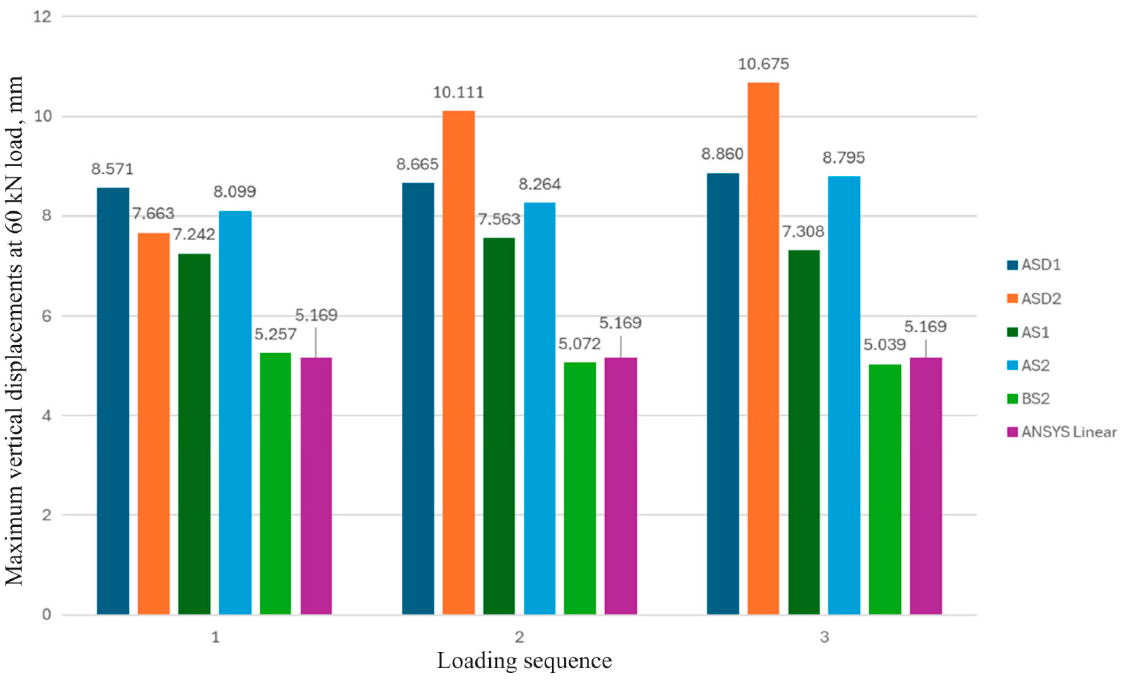
The behaviour of the third group of laboratory specimens is generalised in Figure 18, as the maximum vertical displacements obtained at the concentrated force in 60 kN applied in the middle of the span for three loadings. Results obtained by the FEM models are also indicated in the figure.
It can be concluded, that adding of the polypropylene microfibres increases the maximum vertical displacements of the specimens, causing a decrease in the modulus of elasticity of the concrete layer. The developed FEM model enables us to predict with precision 2.57% of the maximum vertical displacements of the specimens without adding the polypropylene microfibres.
So, two main objectives of the current study were obtained. The possibility to increase the load-carrying capacity of beam-type timber and timber-concrete composite panels by adding of GLT ribs was stated. The effectiveness of the structural materials used is growing in this case. The possibility of decreasing the brittleness of the adhesive timber-to-concrete connection by adding polypropylene microfibres is also stated. However, the determination of the optimum volume fraction and mechanical properties of the fibres can be considered as a task for future investigations.
4. Conclusions
The possibility to increase the load-carrying capacity of beam-type timber and timber-concrete composite panels by adding of GLT ribs was stated. It was stated, that the CLT panel with a span of 1300 mm and thickness of 60 mm, supplied by the two GLT ribs with the dimensions 150 mm × 80 mm, possess a higher 72.5% load-carrying capacity in comparison with the equivalent by the materials consumption CLT panel with thickness in 100 mm. The effectiveness of structural materials used was evaluated as a relation of the load-carrying capacity of the specimens to its materials volume, increasing from 0.650 to 0.951 kN/dm3 with adding the GLT ribs, correspondingly.
It was stated, that the addition of a concrete layer with a thickness of 50 mm and mechanical properties close to C25/30 strength class concrete results in a significant increasing the load-carrying capacity of the CLT beams-type panels with dimensions 1400 mm × 400 mm × 100 mm, by 40.1%.
The possibility of decreasing the brittleness of the adhesive timber-to-concrete connection by the adding of the polypropylene microfibers was stated. It was shown, that the addition of microfibres MAPEI PP-FIBER M6 to the concrete surface layer changes its behaviour under the failure load, the beam-type panels did not collapse brittle and in some specimens, the concrete layer did not disintegrate at all, but rather delaminate from the CLT section. It can be concluded, that the adding of the polypropylene microfibers increases the maximum vertical displacements of the specimens, causing a decrease in the modulus of elasticity of the concrete layer. The developed FEM model enables us to predict with the precision of 2.57% the maximum vertical displacements of the specimens without adding the polypropylene microfibres.
Author Contributions
Conceptualisation, E.B. and D.S.; methodology, E.B., D.S., and P.A.; software, P.A., E.B.; investigation, E.B., D.S., G.S. and A.P.; data curation, A.R., D.S. and P.A.; writing—original draft preparation, D.S. and R.O.; writing—review and editing, D.S. and A.P.; visualisation, E.B.; project administration, D.S. and E.B. All authors have read and agreed to the published version of the manuscript.
Funding
This research was supported by the “ZM-2024/9 Behaviour analyses of different types of timber–concrete beams type panels”.
Data Availability Statement
The data that support the findings of this study are available from the first author [E.B.] upon request.
Acknowledgements
The authors gratefully acknowledge the support of SIA "SKONTO PREFAB", ZAZA TIMBER Production SIA, ConPro SIA, and SIA "Rotho Blaas Latvia" for providing CLT and GLULAM specimens, connecting materials, and transportation.
Conflicts of Interest
The authors declare no conflicts of interest.
References
- Liu, T.; Chen, L.; Yang, M.; Sandanayake, M.; Miao, P.; Shi, Y.; Yap, P.-S. Sustainability Considerations of Green Buildings: A Detailed Overview on Current Advancements and Future Considerations. Sustainability 2022, 14, 14393. [Google Scholar] [CrossRef]
- Basterra, L.-A.; Baño, V.; López, G.; Cabrera, G.; Vallelado-Cordobés, P. Identification and Trend Analysis of Multistorey Timber Buildings in the SUDOE Region. Buildings 2023, 13, 1501. [Google Scholar] [CrossRef]
- Kiviste, M.; Musakka, S.; Ruus, A.; Vinha, J. A Review of Non-Residential Building Renovation and Improvement of Energy Efficiency: Office Buildings in Finland, Sweden, Norway, Denmark, and Germany. Energies 2023, 16, 4220. [Google Scholar] [CrossRef]
- Sizirici, B.; Fseha, Y.; Cho, C.-S.; Yildiz, I.; Byon, Y.-J. A Review of Carbon Footprint Reduction in Construction Industry, from Design to Operation. Materials (Basel) 2021, 14, 6094. [Google Scholar] [CrossRef] [PubMed]
- Chen, L.; Huang, L.; Hua, J.; Chen, Z.; Wei, L.; Osman, A.I.; Fawzy, S.; Rooney, D.W.; Dong, L.; Yap, P.-S. Green Construction for Low-Carbon Cities: A Review. Environ Chem Lett 2023, 21, 1627–1657. [Google Scholar] [CrossRef]
- Bazli, M.; Heitzmann, M.; Ashrafi, H. Long-Span Timber Flooring Systems: A Systematic Review from Structural Performance and Design Considerations to Constructability and Sustainability Aspects. Journal of Building Engineering 2022, 48, 103981. [Google Scholar] [CrossRef]
- Kremer, P.; Symmons, M. Mass Timber Construction as an Alternative to Concrete and Steel in the Australia Building Industry: A PESTEL Evaluation of the Potential. International Wood Products Journal 2015, 6, 2042645315Y.000. [Google Scholar] [CrossRef]
- Ramage, M.H.; Burridge, H.; Busse-Wicher, M.; Fereday, G.; Reynolds, T.; Shah, D.U.; Wu, G.; Yu, L.; Fleming, P.; Densley-Tingley, D.; et al. The Wood from the Trees: The Use of Timber in Construction. Renewable and Sustainable Energy Reviews 2017, 68, 333–359. [Google Scholar] [CrossRef]
- Dukarska, D.; Mirski, R. Wood-Based Materials in Building. Materials 2023, 16, 2987. [Google Scholar] [CrossRef]
- Korolkov, D.; Gravit, M.; Aleksandrovskiy, M. Estimation of the Residual Resource of Wooden Structures by Changing Geometric Parameters of the Cross-Section. E3S Web of Conferences 2021, 244, 04010. [Google Scholar] [CrossRef]
- Premrov, M.; Žegarac Leskovar, V. Innovative Structural Systems for Timber Buildings: A Comprehensive Re-view of Contemporary Solutions. Buildings 2023, 13, 1820. [Google Scholar] [CrossRef]
- Estévez-Cimadevila, J.; Martín-Gutiérrez, E.; Suárez-Riestra, F.; Otero-Chans, D.; Vázquez-Rodríguez, J.A. Timber-Concrete Composite Structural Flooring System. Journal of Building Engineering 2022, 49, 104078. [Google Scholar] [CrossRef]
- Cvetković, R.; Ranković, S.; Mišulić, T.K.; Kukaras, D. Experimental Analysis of Mechanical Behavior of Timber-Concrete Composite Beams with Different Connecting Systems. Buildings 2024, 14, 79. [Google Scholar] [CrossRef]
- Vybranets, Y. , and Deineka, V. Comparative analysis of calculation methods of CLT structures. Theory and Building Practice 2024, 6, 40–48. [Google Scholar] [CrossRef]
- Rogainis, A.; Serdjuks, D.; Buka-Vaivade, K.; Akishin, P.; Sahmenko, G.; Briuka, E.; Lapkovskis, V. Verification of a Simplified Design Method for Timber–Concrete Composite Structures with Metal Web Timber Joists. Appl. Sci. 2024, 14, 1457. [Google Scholar] [CrossRef]
- Deam, B.L.; Fragiacomo, M.; Buchanan, A.H. Connections for Composite Concrete Slab and LVL Flooring Systems. Mater Struct 2008, 41, 495–507. [Google Scholar] [CrossRef]
- Andaque, H.; Sadeghi, K. Comparison Between Timber Concrete Composite Slab and Solid Slab for Residential Buildings. International Journal of Innovative Science and Research Technology 2023, 8, 612–623. [Google Scholar] [CrossRef]
- Winandy, J.E.; Morrell, J.J. Improving the Utility, Performance, and Durability of Wood- and Bio-Based Composites. Annals of Forest Science 2017, 74, 1–11. [Google Scholar] [CrossRef]
- Buka-Vaivade, K.; Serdjuks, D.; Zvirina, D.; Pakrastins, L. Experimental Analysis of Timber-concrete Composite Behaviour with Synthetic Fibres. Journal of Physics: Conference Series 2023, 2423, 012014. [Google Scholar] [CrossRef]
- Buka-Vaivade, K.; Serdjuks, D.; Pakrastins, L. Cost Factor Analysis for Timber–Concrete Composite with a Lightweight Plywood Rib Floor Panel. Buildings 2022, 12, 761. [Google Scholar] [CrossRef]
- Buka-Vaivade, K.; Serdjuks, D. Behavior of Timber-Concrete Composite with Defects in Adhesive Connection. In Proceedings of the Procedia Structural Integrity; Elsevier B.V.: Madeira, Portugal, 2022, 37, 563–569. [Google Scholar] [CrossRef]
- Vasiljevs, R.; Serdjuks, D.; Buka-Vaivade, K.; Podkoritovs, A.; Vatin, N. Load-carrying capacity of timber-concrete composite panels. Magazine of Civil Engineering. 2020, 93, 60–70. [Google Scholar] [CrossRef]
- EN 1995-1-1 :2004+A 1 - Eurocode 5: Design of Timber Structures - Part 1-1: General - Common Rules and Rules for Buildings 2008.
- Bajzecerová, V. Bending Stiffness of CLT-Concrete Composite Members - Comparison of Simplified Calculation Methods. Procedia Engineering 2017, 190, pp–15. [Google Scholar] [CrossRef]
- Dias, A.; Skinner, J.; Crews, K.; Tannert, T. Timber-Concrete-Composites Increasing the Use of Timber in Construction. Eur. J. Wood Prod. 2016, 74, 443–451. [Google Scholar] [CrossRef]
- Briuka, E. Analysis of Structural Materials Effectiveness Increase of Timber and Timber-concrete Beam-type Panels. M.S. thesis, RTU: Riga, 2024.
- Abdul-Razzak, A. and Mohammed Ali, A. Modelling and numerical simulation of high strength fibre reinforced concrete corbels Applied Mathematical Modelling 2011, 35, 2901–2915. [Google Scholar] [CrossRef]
- Bhargava, P. , Sharma, U. and Kaushik, S. Compressive stress-strain behavior of small scale steel fibre reinforced high strength concrete cylinders Journal of Advanced Concrete Technology 2006, 1, 109–121. [Google Scholar] [CrossRef]
Figure 1.
CLT beam-type panel with glued laminated timber longitudinal ribs.
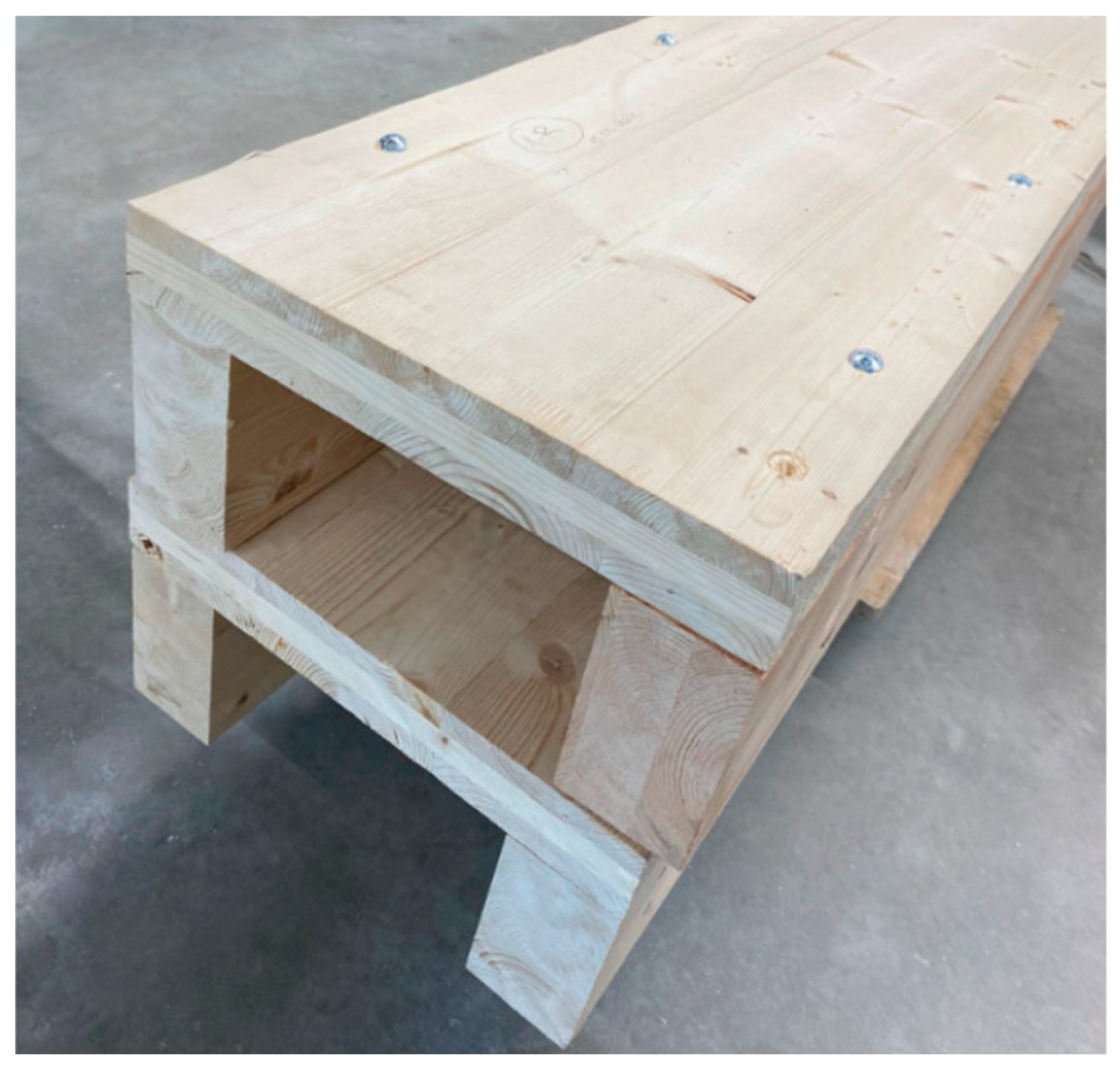
Figure 2.
Transformed to the timber of CLT layers with the grains, oriented parallel to the longitudinal axis of the member section of the TCC beam-type panel.
Figure 2.
Transformed to the timber of CLT layers with the grains, oriented parallel to the longitudinal axis of the member section of the TCC beam-type panel.
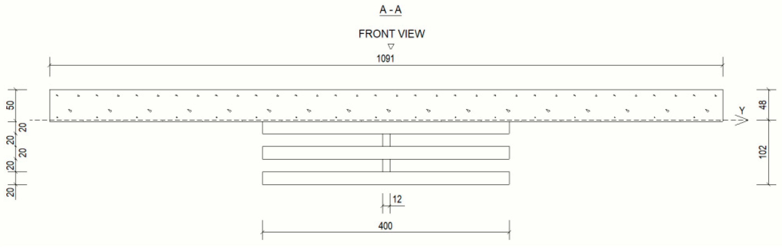
Figure 3.
The first sub-group of the laboratory specimens – CLT panels with dimensions 1400 mm × 400 mm × 100 mm.
Figure 3.
The first sub-group of the laboratory specimens – CLT panels with dimensions 1400 mm × 400 mm × 100 mm.
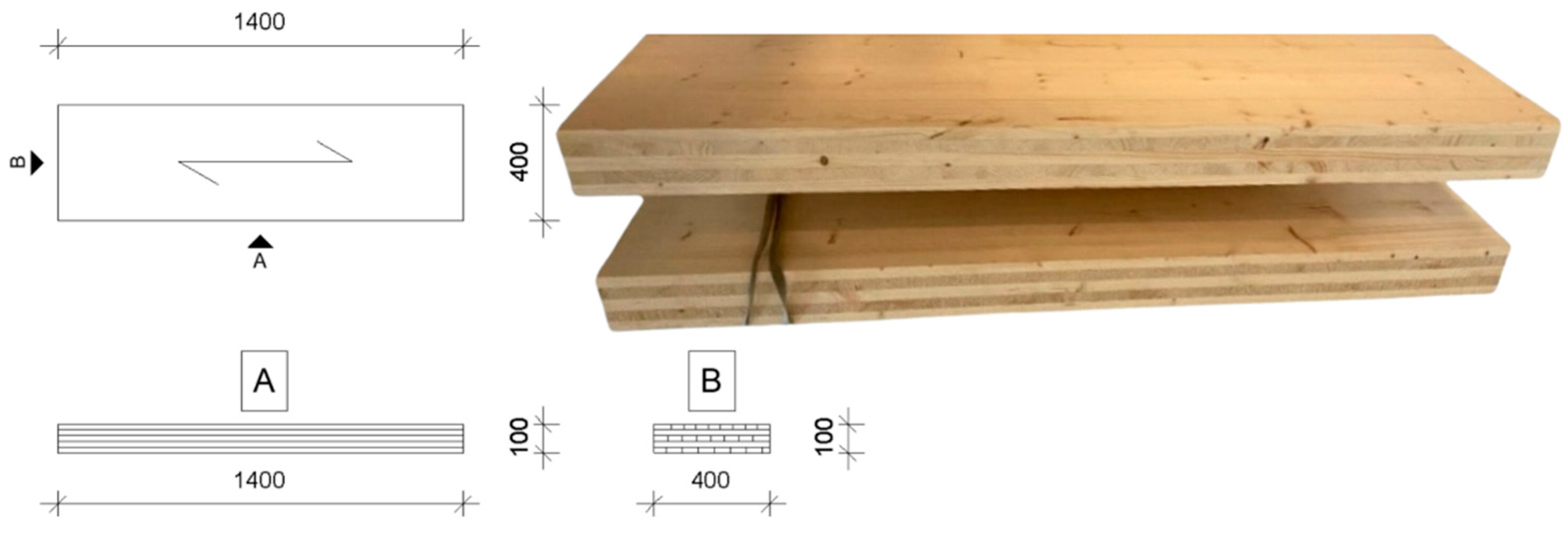
Figure 4.
The second sub-group is presented by the two CLT panels with dimensions 1400 mm × 400 mm × 60 mm, strengthened by the two glued laminated timber ribs with dimensions 150 mm × 80 mm.
Figure 4.
The second sub-group is presented by the two CLT panels with dimensions 1400 mm × 400 mm × 60 mm, strengthened by the two glued laminated timber ribs with dimensions 150 mm × 80 mm.
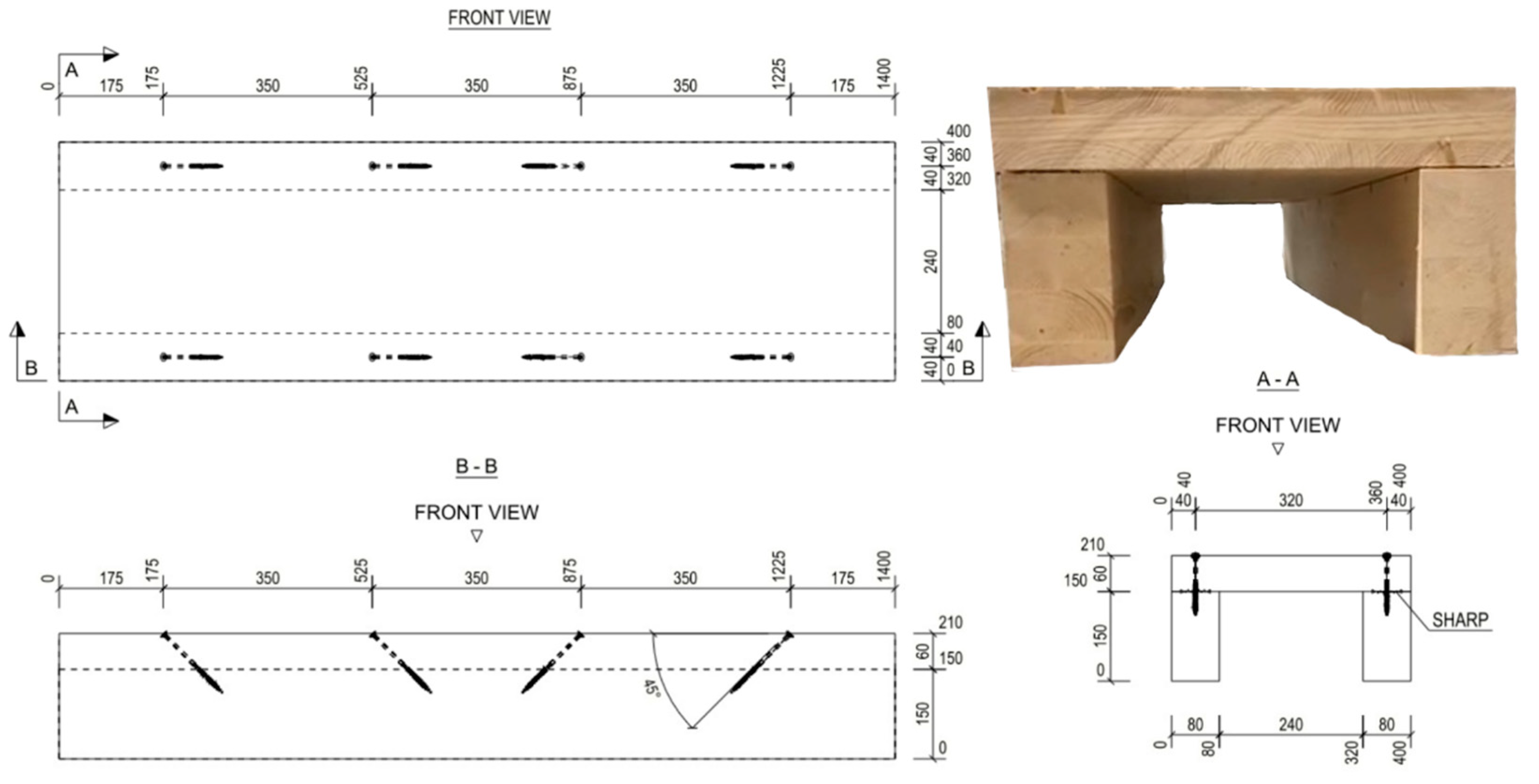
Figure 5.
The second group of laboratory specimens: a) specimen of sub-group A; b) specimen of sub-group B; c) specimen of sub-group C.
Figure 5.
The second group of laboratory specimens: a) specimen of sub-group A; b) specimen of sub-group B; c) specimen of sub-group C.
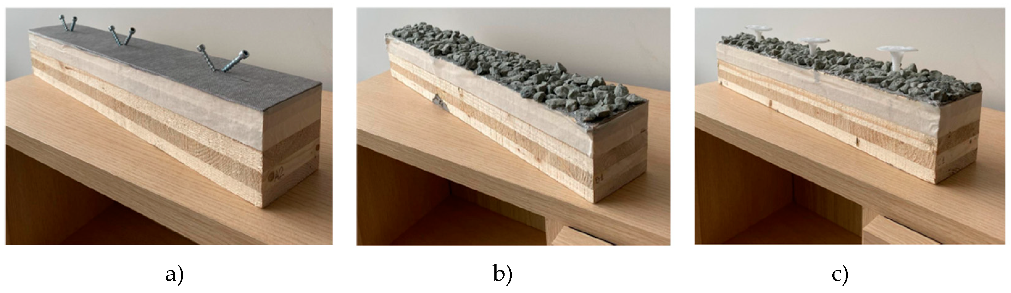
Figure 6.
The second group of laboratory specimens: a) designations of specimens in the sub-groups; b) specimens placed in the moulds in the process of concrete hardening.
Figure 6.
The second group of laboratory specimens: a) designations of specimens in the sub-groups; b) specimens placed in the moulds in the process of concrete hardening.
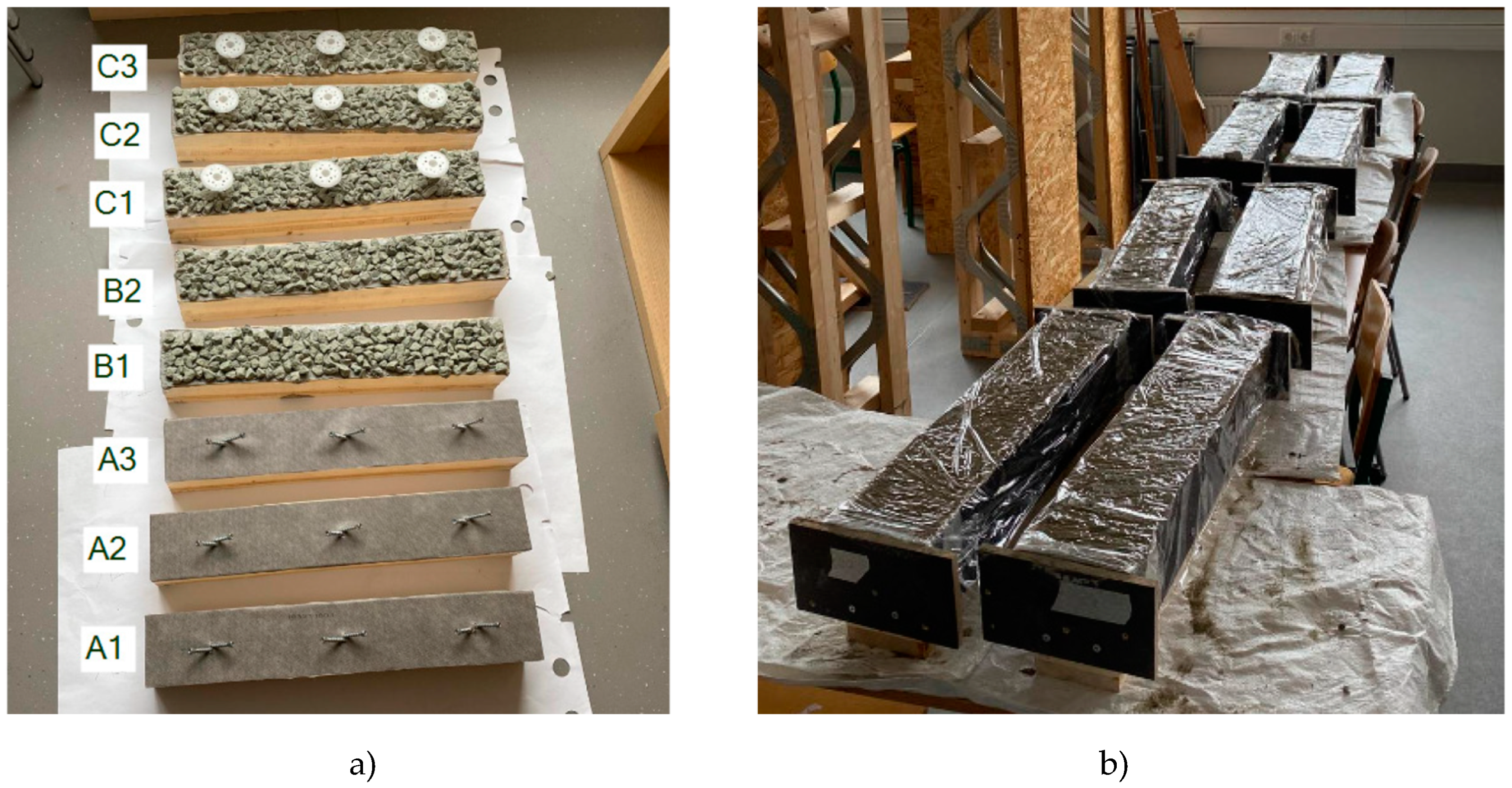
Figure 7.
The third group of laboratory specimens: a) the first sub-group signed as ASD; b) the second sub-group, signed as AS; c) the third sub-group, signed as BS.
Figure 7.
The third group of laboratory specimens: a) the first sub-group signed as ASD; b) the second sub-group, signed as AS; c) the third sub-group, signed as BS.
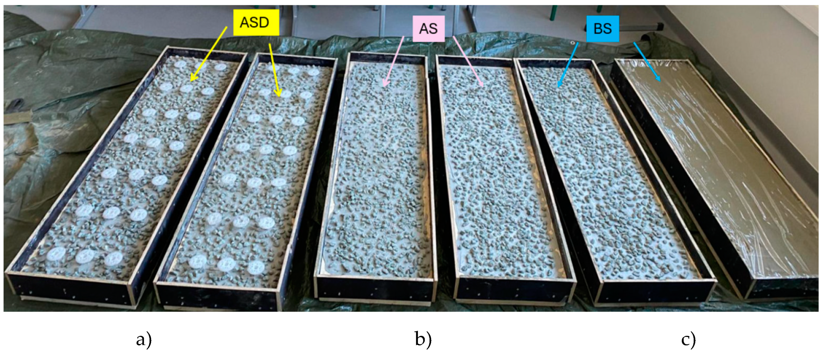
Figure 8.
Testing devices: a) for the first and third groups of laboratory specimens; b) for the second group of laboratory specimens.
Figure 8.
Testing devices: a) for the first and third groups of laboratory specimens; b) for the second group of laboratory specimens.
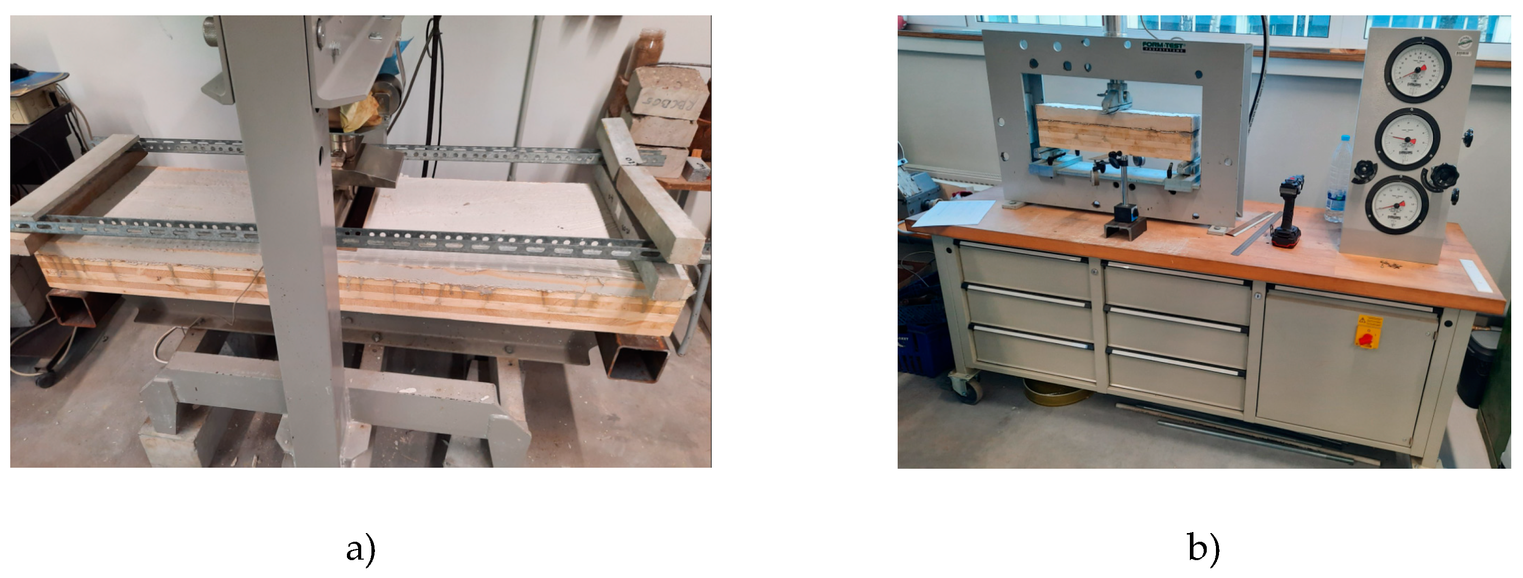
Figure 9.
FEM models of the first group of laboratory specimens: a) FEM of the first sub-group specimens under the action of concentrated force in 30 kN; b) FEM of the first sub-group specimens under the action of concentrated force in 50 kN.
Figure 9.
FEM models of the first group of laboratory specimens: a) FEM of the first sub-group specimens under the action of concentrated force in 30 kN; b) FEM of the first sub-group specimens under the action of concentrated force in 50 kN.
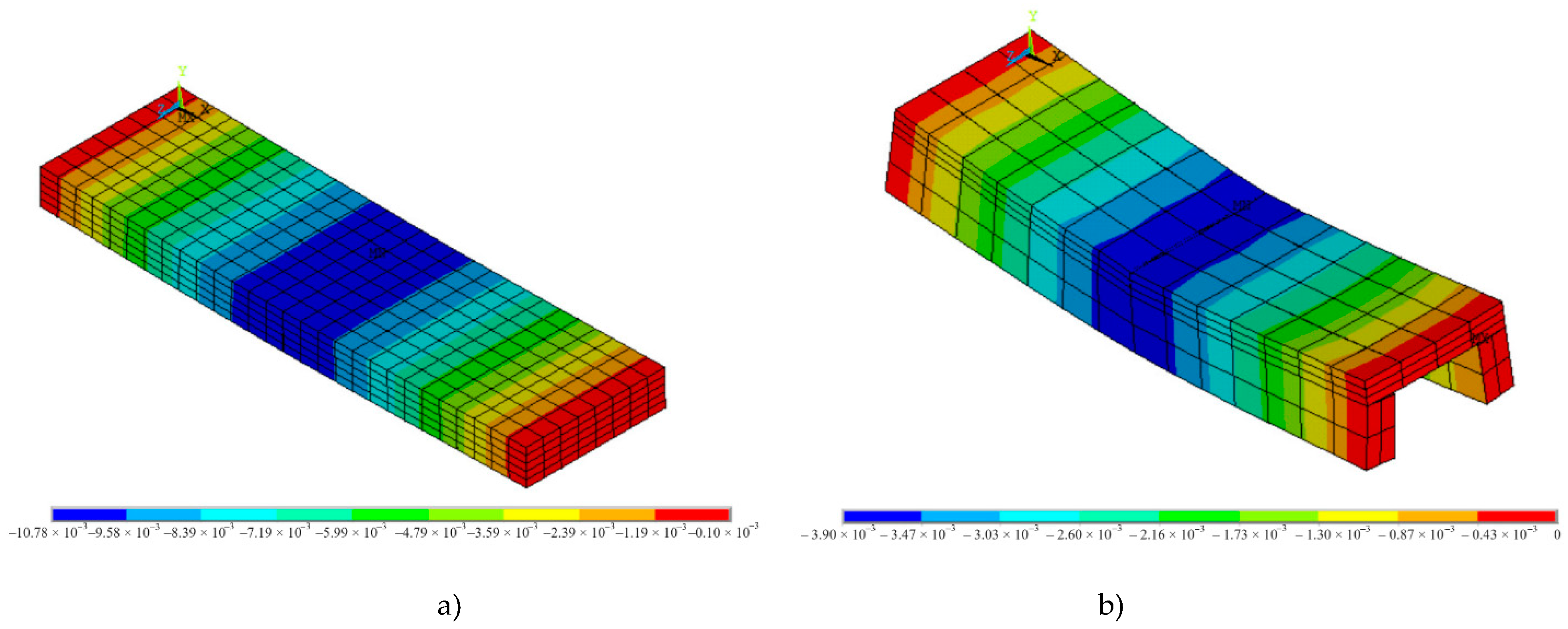
Figure 10.
FEM models of the second and third groups of laboratory specimens: a) FEM of the second (sub-group B) group of specimens under the action of concentrated force in 10 kN; b) FEM of the third (sub-group BS) group of laboratory specimens under the action of concentrated force in 60 kN.
Figure 10.
FEM models of the second and third groups of laboratory specimens: a) FEM of the second (sub-group B) group of specimens under the action of concentrated force in 10 kN; b) FEM of the third (sub-group BS) group of laboratory specimens under the action of concentrated force in 60 kN.
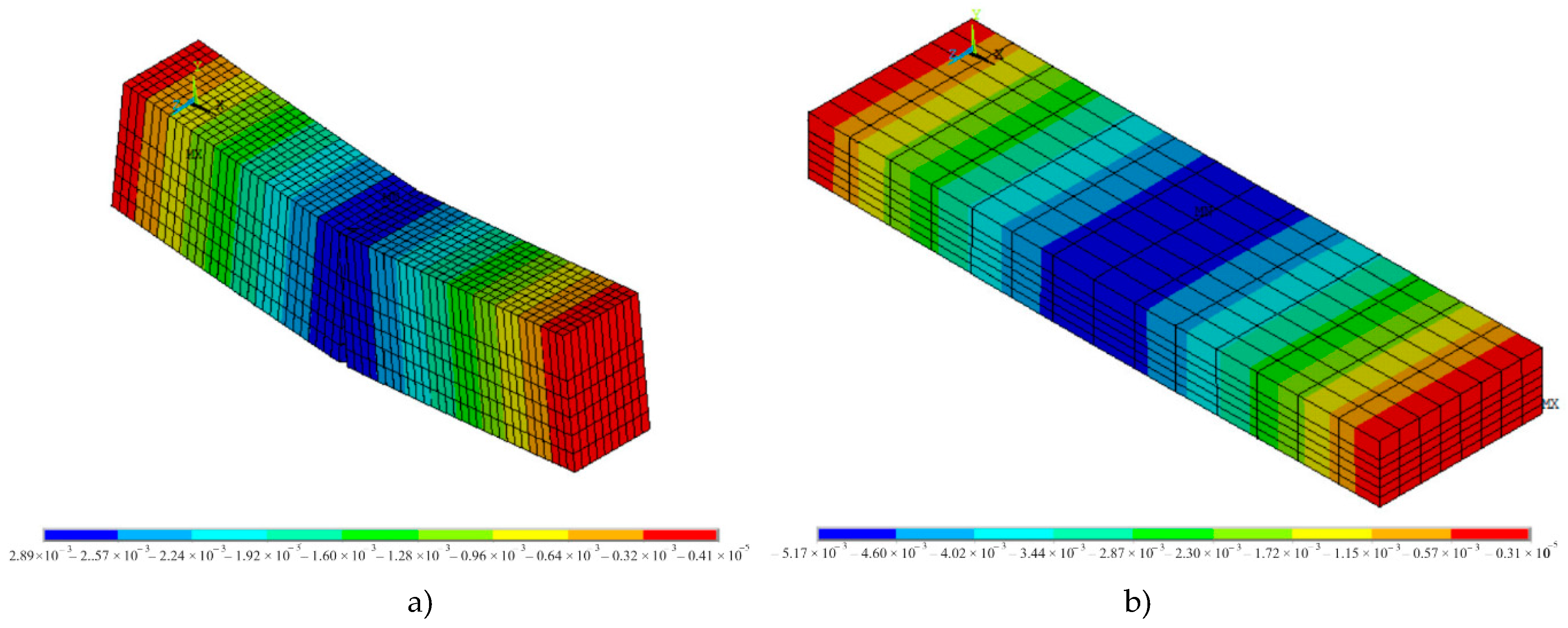
Figure 11.
Design schemes of laboratory specimens: a) the first and the third groups; b) the second group.
Figure 11.
Design schemes of laboratory specimens: a) the first and the third groups; b) the second group.
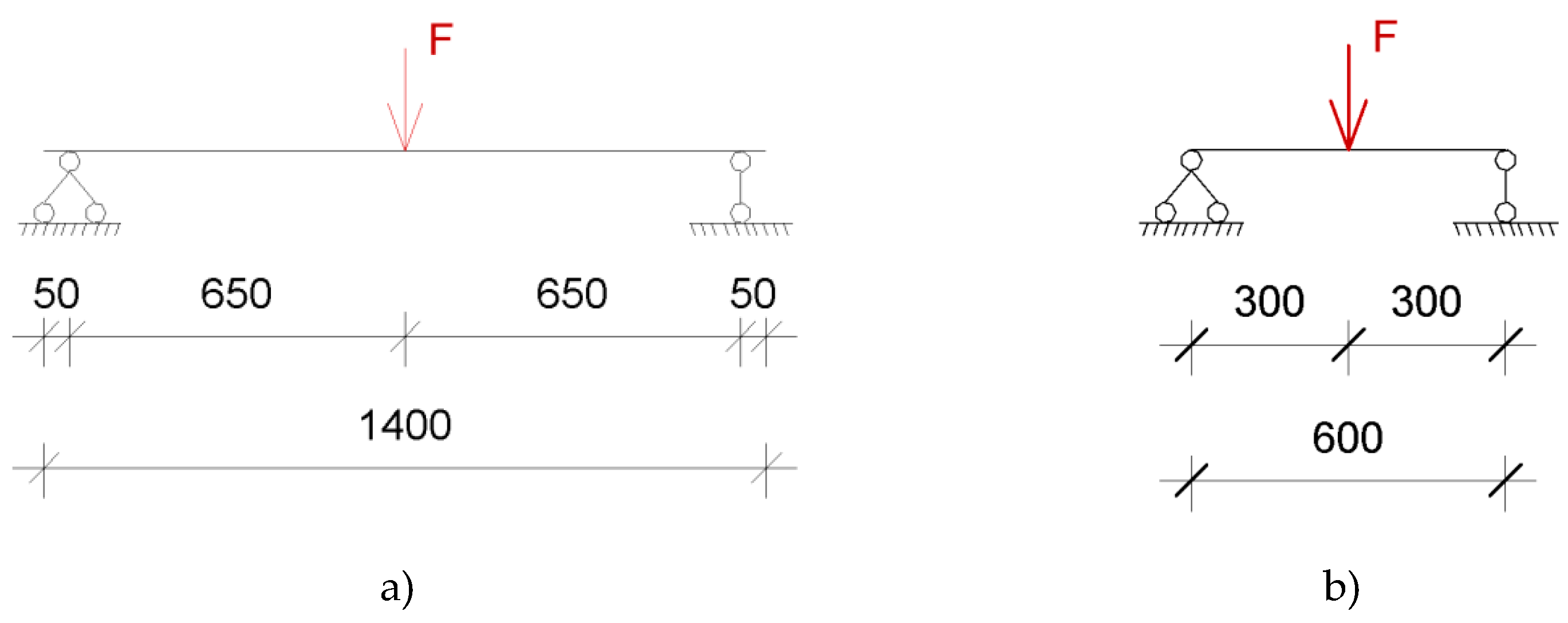
Figure 12.
Dependence of the maximum vertical displacements on the vertical load, applied as a concentrated force in the middle of the span, for the first sub-group of the first group specimens, where 1st and 2nd specimen_exp – obtained by the laboratory experiment, FEM – by the FEM method, SMD and SMD_shear – by the simplified design method without and with taking into account the shear force influence on the vertical displacements of the panels.
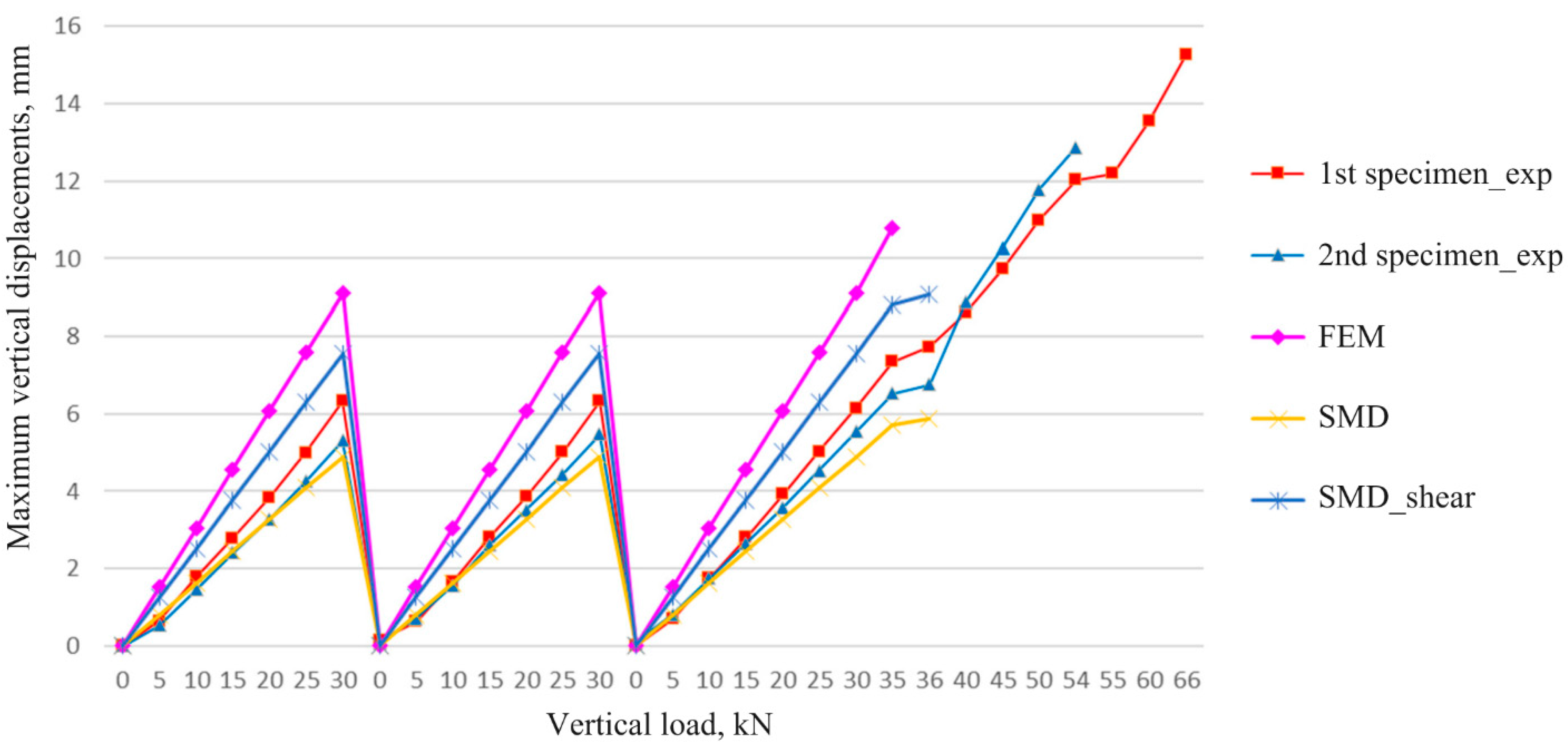
Figure 13.
Dependence of the maximum vertical displacements on the vertical load, applied as a concentrated force in the middle of the span, for the 2nd sub-group of the 1st group of the specimens, where 3rd and 4th specimen_exp – obtained by the laboratory experiment, FEM – by the FEM method, SMD and SMD_shear – by the simplified design method without and with taking into account the shear force influence on the vertical displacements of the panels.
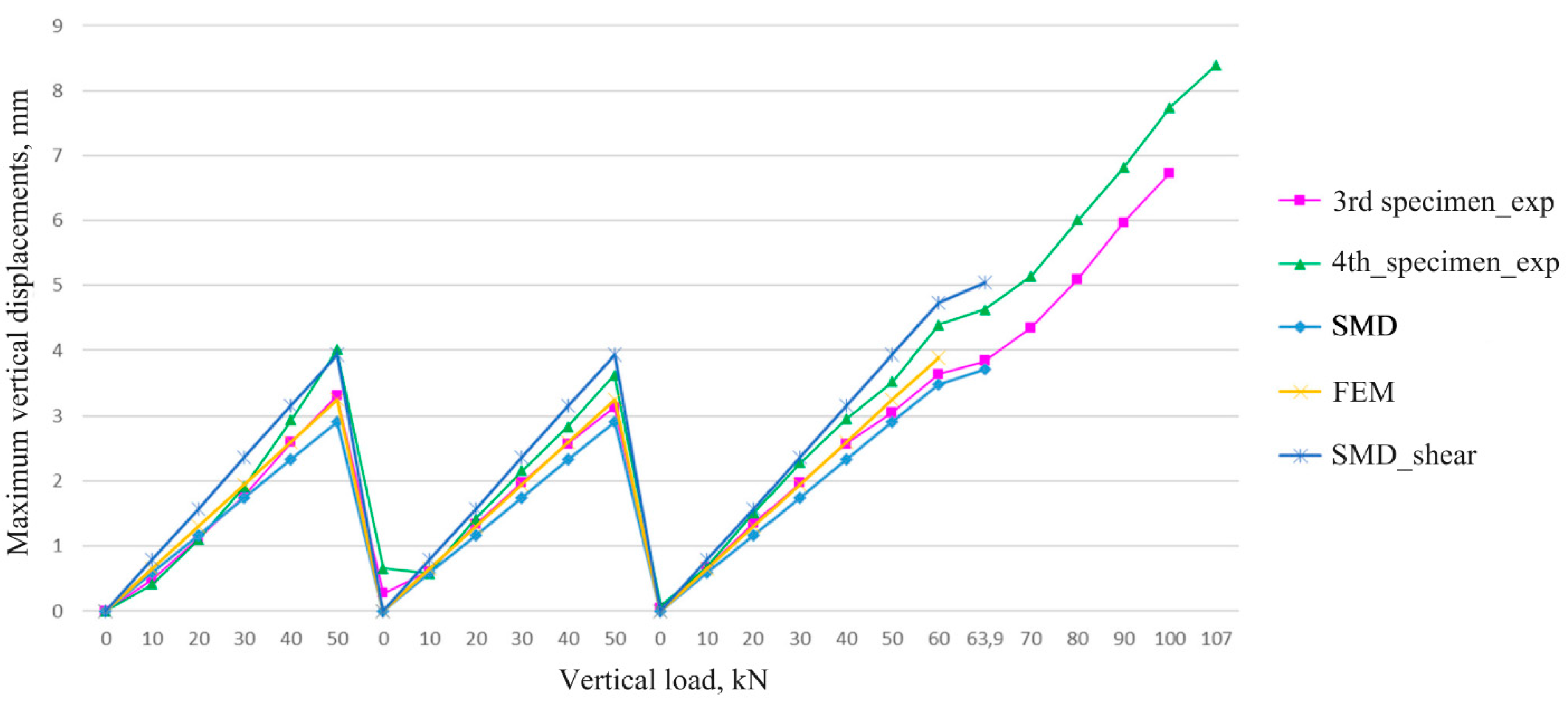
Figure 14.
Dependence of the effectiveness of structural materials use K1 on the geometric parameters of the specimens: a) on the depth of the glued laminated timber ribs; b) on the depth of the CLT component.
Figure 14.
Dependence of the effectiveness of structural materials use K1 on the geometric parameters of the specimens: a) on the depth of the glued laminated timber ribs; b) on the depth of the CLT component.
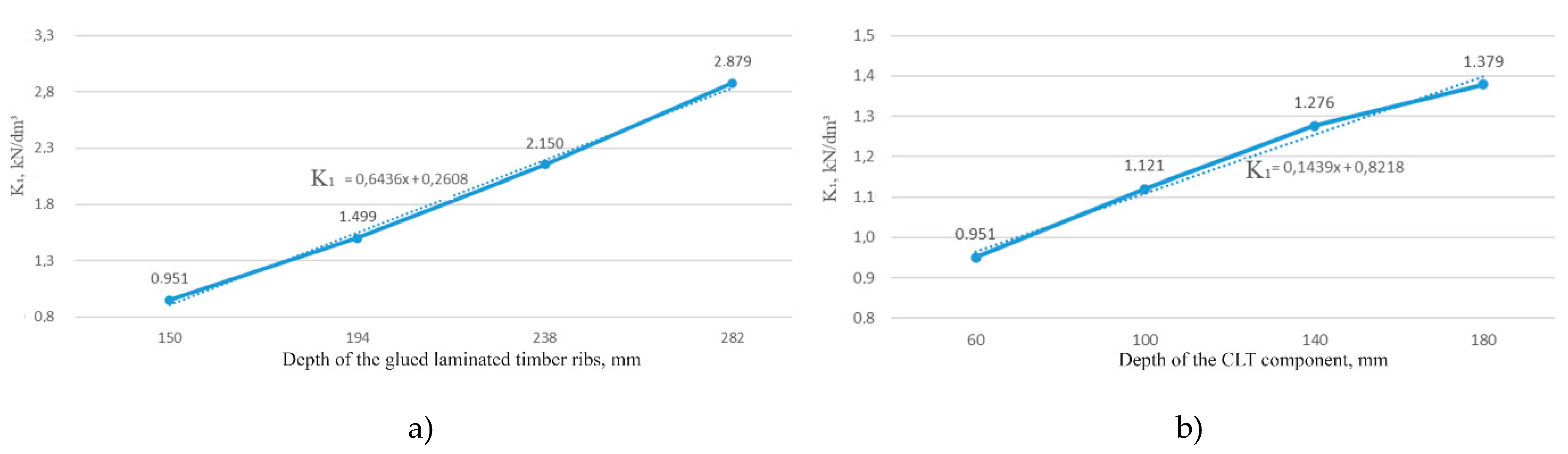
Figure 15.
The failure modes of the specimens of all three sub-groups of the second group: a) first sub-group (specimen A3); b) second sub-group (specimen B1); c) third sub-group (specimen C2).
Figure 15.
The failure modes of the specimens of all three sub-groups of the second group: a) first sub-group (specimen A3); b) second sub-group (specimen B1); c) third sub-group (specimen C2).
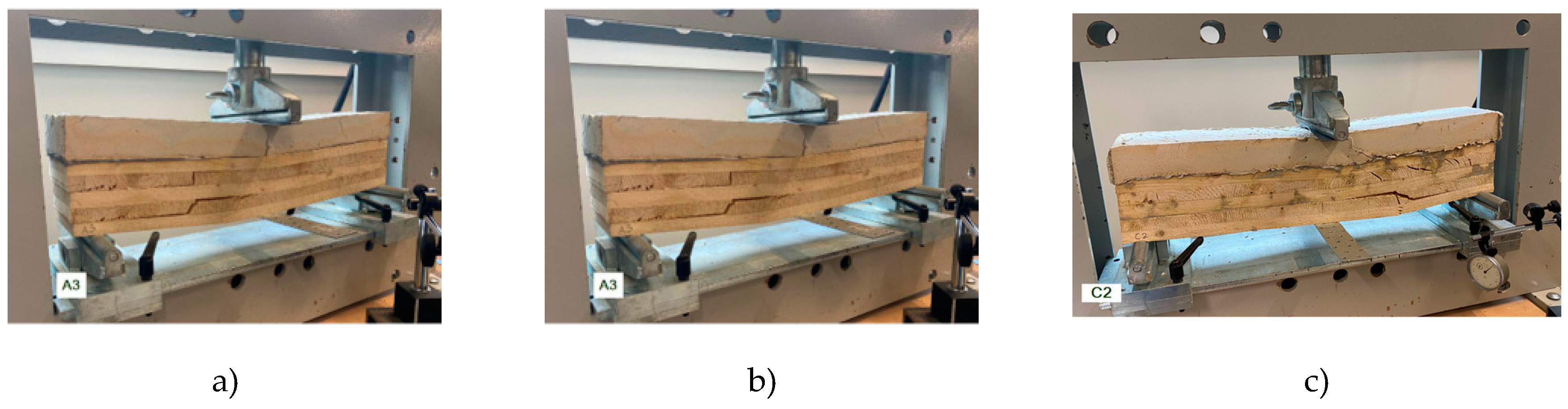
Figure 16.
The dependence of the maximum vertical displacements on the vertical load applied as a concentrated force in the middle of the span for the third group of laboratory specimens.
Figure 16.
The dependence of the maximum vertical displacements on the vertical load applied as a concentrated force in the middle of the span for the third group of laboratory specimens.
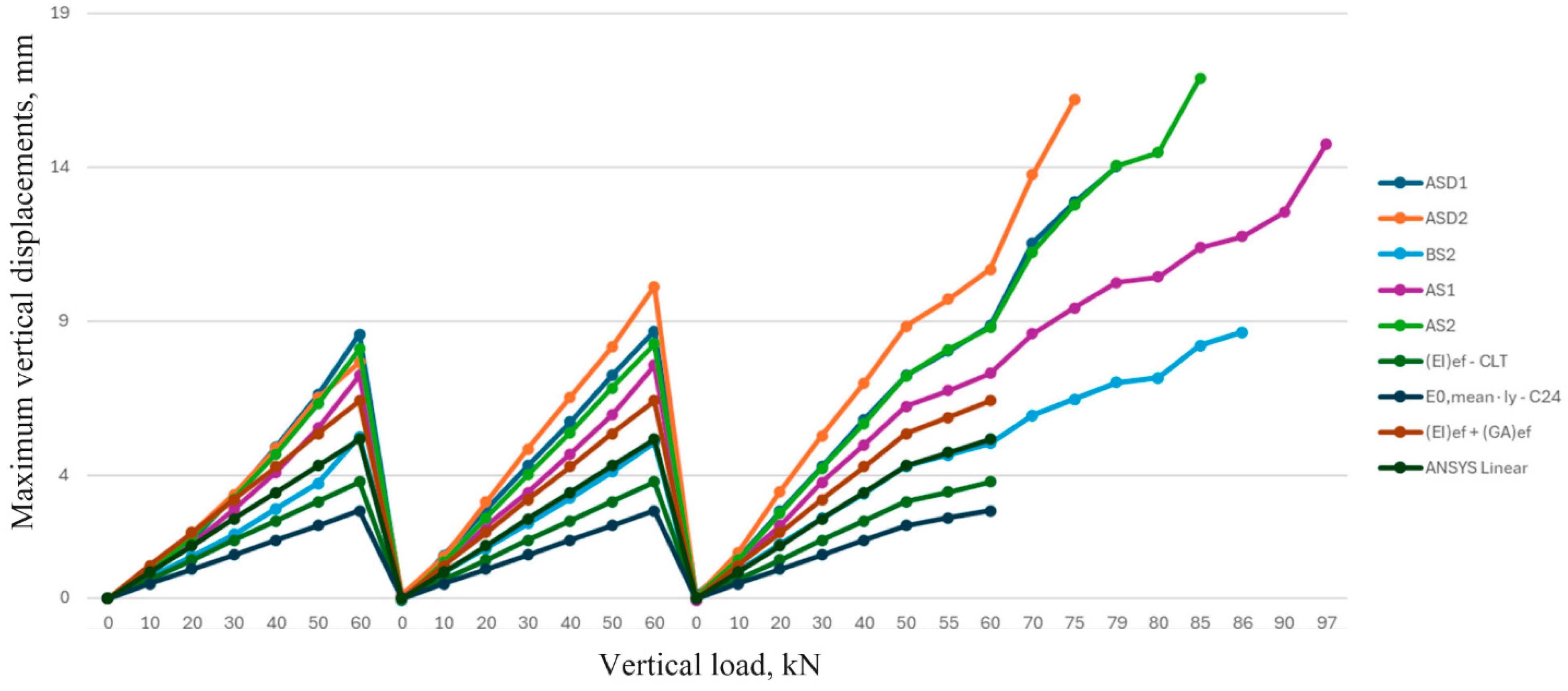
Figure 17.
The failure mode of the third group specimens: a) sub-group BS; b) sub-group AS.
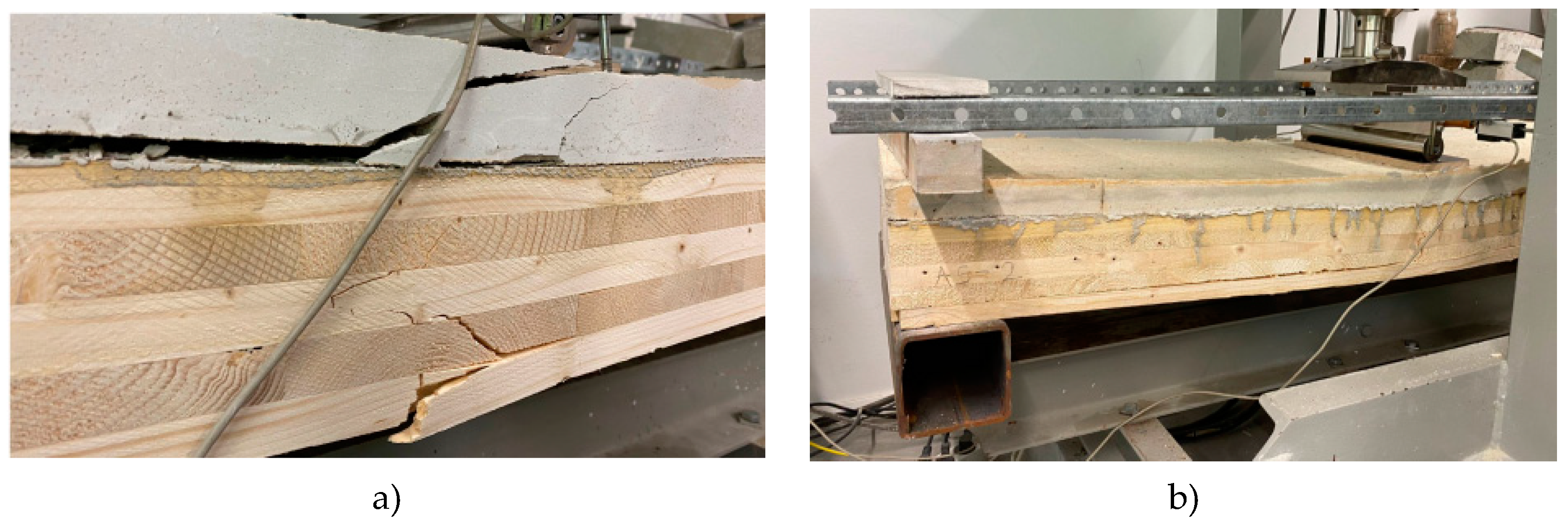
Figure 18.
Maximum vertical displacements obtained for the third group of laboratory specimens at the concentrated force in 60 kN applied in the middle of the span.
Figure 18.
Maximum vertical displacements obtained for the third group of laboratory specimens at the concentrated force in 60 kN applied in the middle of the span.
Disclaimer/Publisher’s Note: The statements, opinions and data contained in all publications are solely those of the individual author(s) and contributor(s) and not of MDPI and/or the editor(s). MDPI and/or the editor(s) disclaim responsibility for any injury to people or property resulting from any ideas, methods, instructions or products referred to in the content. |
© 2024 by the authors. Licensee MDPI, Basel, Switzerland. This article is an open access article distributed under the terms and conditions of the Creative Commons Attribution (CC BY) license (https://creativecommons.org/licenses/by/4.0/).
Copyright: This open access article is published under a Creative Commons CC BY 4.0 license, which permit the free download, distribution, and reuse, provided that the author and preprint are cited in any reuse.


