
Submitted:
24 October 2023
Posted:
25 October 2023
You are already at the latest version
Abstract
Keywords: keyword 1; keyword 2; keyword 3 (List three to ten pertinent keywords specific to the article yet reasonably common within the subject discipline.)
Keywords:
Cement
; Geothermal
; Drying shrinkage
; Fibers
; Rubber
; Additives
; Temperature cycles
; Radial cracks
; Leakage
; Microannulus
1. Introduction
In order to meet the targets set in the Paris agreement, fossil fuels need to be replaced with other sources of energy. Consequently, the supply of energy in the future is anticipated to come from a mix of various renewable sources including geothermal energy. This particular energy source could provide significant amounts of both electrical and thermal energy, up to respectively 3% and 5% of the global demand in 2050 [1]. However, geothermal wells must be durable and sustainable to reduce the financial risks and thus making investment in geo-energy more attractive.
Geothermal pipes are susceptible to corrosion (rust). Produced water from geothermal wells has high temperature, high salinity, and contains chemicals (some naturally occurring and others are added to prevent corrosion). If corrosion weakens or generates a hole in the pipes, salt water can leak into the freshwater aquifers that provide drinking water. Such well integrity issues are costly to repair and jeopardize the economics of the geothermal projects. The current technology for sealing is the placement of well cement into the annulus between casing and formation to provide mechanical stability and structural support as well as zonal isolation. A common case of leakage arise due to failure of the cement interfaces in the well, either the cement/casing interface, or the cement/formation interface possibly followed by corrosion of the steel pipes. Consequently, attention need to be paid to the behavior of cement under challenging geothermal conditions such as (high) temperature variations. These conditions subject casing and cement sheaths to thermal and stress shocks as well as chemically aggressive environments. Thermal cycling due to a pause and resumption of activity in geothermal wells will cause casing, cement, and formation to repeatedly expand and contract accordingly to their distinct thermal expansion coefficients introducing stresses on and between the wellbore components. As a result, failures such as debonding, shear and radial cracking of the annular cement sheath can occur [2,3]. Both the amplitude and the frequency of the temperature cycles can initiate damage of the cement seal and cyclic loading can lead to fatigue growth of defects/failures within the system, compromising zonal isolation and may result in casing corrosion and deterioration of well integrity. The cycles may be of short (daily) or long (seasonal) frequencies. Even for intermediate and low-temperature wells, common Ordinary Portland Cement (OPC) based formulations may develop problems with strong temperature variations (4, 5].
Consequently, a cement recipe generating a material resistant to thermal cycles is required for a robust long-term performance of a geothermal installation. Such a resistance can be achieved by the introduction of flexible cements which are more able to withstand the stresses generated by fluctuations in downhole pressure and temperature. An introduction of micro-fibers such as wollastonite [6] or other fibrous materials [7] results in an increase in flexural strength and a promotion of pore discontinuity/permeability reduction in cement. Furthermore, fiber reinforcement increases the resistance to cracking induced by thermal effects or shrinkage by arresting the crack growth and by transferring stresses across a crack [3]. A review by Doğan and Demir [8] discusses all aspects of fiber reinforced concrete with a comparison of concrete properties such as shrinkage and crack formation, compression, splitting tensile and flexural strength, toughness and elastic modulus. As a result, it was shown that the addition of (polymer) fibers increases cement durability [3].
Improved cement ductility can also be achieved by introducing tire rubber particles into cement-based materials [9]. Tire rubber particles have the potential to enhance the toughness of cement by interfering with crack propagation processes through dissipation of stresses. The ductile deformation of the rubber particles leads to the stabilization of defects and the prevention of brittle cracking [10].
Additionally, polymer latex is widely used in civil engineering applications for improvement of service performance of concrete and mortar [11]. The use of a ductile polymer as a modifier seems to be a promising strategy in improving microstructure and enhancing the durability of cement mortar and concrete [12]. Styrene butadiene rubber (SBR) latex has been widely used in fresh mortar and concrete, [13]. In the case of mortars modified by latex rubbers, Justnes and Øye [14] showed that the latex forms a continuous network if the polymer content exceeds 10 wt%. This polymer network explains the improvement of the tensile and/or flexural strength. Song et al. used a combination of latex powder and rubber to modify oil well cement recipes [15]. This combination has shown a significant improvement in flexural strength, impact strength, and ductility of the cement as well as in decreasing fluid loss of the slurry. A mixture of 3 wt.% latex powder and 2 wt.% rubber results in the formation of a three-dimensional, flexible network structure which improves the elasticity and toughness of cement stone.
The aim of this study is to identify reasons for failure (mechanisms) of casing cement formulations as used in geo-thermal wells for medium and low temperature geo-thermal systems. In addition, we have designed new cement formulations for resistance to thermal cycling and drying shrinkage by incorporation of rubber particles, latex and fibers and mixtures thereof as well as by adding silica fume and pozzolan. The new formulations are tested under cyclic thermal loading conditions as well as under different drying conditions (relative humidity, RH). Finally, the influence of the curing conditions (ambient as well as well conditions) on the cement properties has been investigated.
2. Materials and Methods
Cement Formulations
Various formulations were made by mixing different ingredients including rubber particles, silica fume, latex, pozzolan, and polymer fibers. All the recipes tested included class G cement (Dyckerhoff Well Cement) as the base material. The additives tested in this work are:
- Crumb rubber powder from waste tire rubber (WTR) with a granule size less than 0.5 mm obtained from Kargo Recycling Nederweert, The Netherlands,
- Basoblock™ LD 105, a styrene-butadiene latex from BASF,
- Paragas® , a modified polyethylenimine (water soluble polymer) from BASF,
- Pozzolan from Heidelberg Cement (50% clinker, 25% slag en 25% pozzolan),
- Polypropylene (PP) and polyacrylonitrile (PAN) fibres 3 mm length, 35 and 12 micron diameter from Shandong Dachuan New Materials Co.,Ltd, China.
An overview of the samples prepared is given in Table 1.
The formulations in Table 1 were dry blended. Cement slurries were prepared by adding 44 % bwoc of water using a stirrer at 3000 rpm. The slurry was poured into the mold after 3 min of stirring.
Sample Preparation
Down-scaled annular samples were designed to represent downhole cement sheaths in geothermal wells. The samples were used for thermal cycling tests. The samples were created by placing steel pipes with an inner diameter of 40 mm and a wall thickness of 2 mm, in in polypropylene (PP) molds with an inner diameter of 60 mm. The length of the samples was 100 mm. The gap between the steel pipe and the PP mold was initially filled with seawater or freshwater. The cement slurry was then poured in the gap replacing seawater (Figure 1A). Subsequently, the mold was closed and allowed to cure under ambient conditions for 7 days before the mold was removed (Figure 1C).
Additionally, core samples for testing of drying shrinkage of cores ware prepared by pouring the formulations prepared as described above in cylindrical PP molds with an inner diameter of 30 mm and a height of 65 mm. After curing for 7 days under ambient conditions the samples were demolded and aged under various relative humidity conditions for 1 month.
Thermal Cycling Tests
For thermal testing, the samples (still in plastic molds) were placed in 1 L autoclaves and cured for 7 days at 100 °C and 100 bar pressure (Figure 1B). The molds were inserted in seawater with the water level below the top of the PP mold to supply moisture during curing and to avoid leaching of cement components. Thermal cycling tests were performed by applying moderate thermal cycles (100 °C → 18 °C → 100 °C) with a heating speed of 5 K/min and cooling speed (quenching using ice-water) of 20 K/min. Each sample was exposed to 10 thermal cycles, as described. The impact of confining stress on cement was investigated in these experiments.
After the thermal cycling, the samples were inspected for damage (cracks), by optical and acoustic scanning microscopy (SAM), using a Sonix Echo with a 30 MHz acoustic lens in reflection mode. Selected core samples were also analyzed by CT-scanning (Phillips) as well as by scanning electron microscopy (SEM).
Drying Shrinkage Tests
Selected samples (after 7 days of curing) were exposed to different constant relative humidity (RH) environments in closed boxes to study the effect of drying shrinkage. RH values were controlled by having saturated salt solutions inside of the closed boxes (see Figure 2, Table 2). The samples stored under conditions of constant RH were inspected daily for damage and the width of appearing cracks was measured using a Keyence digital microscope VHX 600. Furthermore, the hardness of the cement formulations was measured using a micro indenter Fischerscope H100C.
3. Results
Thermal Cycling Tests
Only a limited number of samples listed in Table 1 were exposed to thermal cycling at 100 C and 100 bar pressure (TestCEM B, TestCEM si35, TestCEM si40, TestCEM R20, TestCEM PAN and TestCEM PP). All the tested samples showed no sign of damage after 10 cycles between 100 and 18 °C. The curing pressure and temperature and the displaced fluid (freshwater versus saltwater) did not change the results. Figure 3 shows an image of cement samples after the cycling test. Visually, the cement that has displaced saltwater in the annulus looked different but optical microscopy indicated no damage in the samples. The results show that in low-enthalpy geothermal wells, temperature cycles alone do not necessarily damage class G cement. However, in the tests performed, the stress conditions in cement are not completely the same as present in downhole conditions. Therefore, it does not rule out the impact of thermal stresses on cement.
Drying Shrinkage Tests
Samples aged/stored in air eventually developed tensile cracks as shown in Figure 4a. These cracks appeared after approximately two weeks of storage under ambient conditions (55 % RH, 23 °C). An investigation by scanning acoustic microscopy indicated the extension of the cracks through the whole thickness/length of the cement sheath (Figure 4b). The tensile crack coincided with (partial) debonding of the cement sheath from the steel pipe as detected by SAM (Figure 4c). Debonding is seen on the left side as a micro-annulus filled with air which causes the bright contrast. The de-bonded cement sheath and the steel pipe could be easily separated from the cement sheath pipe (Figure 5).
This indicates that cement integrity is perhaps more sensitive to drying than temperature cycles alone. Drying in cement causes partial depletion of pore fluids which in turn induces capillary stress in the sample. This leads to drying shrinkage which can cause cracks; an effect known and intensively studied for concrete [17,18,19,20,21]. Consequently, cured samples were exposed to different RH levels (Table 2) to investigate the resistance of each formulation to drying shrinkage, as an overall measure of ductility and tendency for brittle cracking. All formulations were exposed to RH levels between 22.7 and 84 %. The appearance of crack(s), mostly radial, was recorded over time and the width of the crack opening was measured using the digital microscope, at least three different positions of the crack and at least 6 measurements per positions were performed (Figure 6).
It was found that the developed crack width (opening) depends on the RH value; storage at conditions with lower RH results in the development of larger crack width. Figure 7 shows the dependency of the crack opening on the RH of the storage for four formulations. TestCEM B sample (neat class G) shows an initial crack at 84% RH with an aperture of approximately 90 microns. As humidity decreases, the size of the aperture increases to 350 microns at 43% RH. The aperture remains constant as RH decreases below 43%. The TestCEM Si35 sample shows an initial crack at 75% RH with an estimated aperture of 60 micron. The size of the crack increases at lower RH levels to 350 microns. TestCEM R10 sample shows initial cracking at 75% humidity starting at 170 microns. The TestCEM R20 (20% rubber particles) show the most resistance to cracking, where the first crack appears at a humidity of 53%.
Figure 8 shows the time it takes for the crack to appear at different humidity levels. TestCEM B sample shows cracking after 10 days at 83% humidity. However, the TestCEM R10 takes 20 days to show the first crack at 75% humidity. These results indicate that the samples including rubber take longer to develop cracks at higher RH values. At RH below 40%, both samples show cracks at the same time frame.
A precise measurement of the crack width is somewhat difficult in case of very large openings since such samples show also partially delamination/debonding of the cement sheath with the steel pipe and needs therefore additional care in the measurements. Also, such samples show a (partial) closure of the cracks if stored (again) under higher RH environment after crack formation.
Samples TestCEM PP, TestCEM PAN, TestCEM PAN-R10 and TestCEM PAN BB only show small, non-continuous cracks (15-30 m, see Figure 9) even at RH less than 43%.
The sample TestCEM PAN-BB showed an interesting morphology, presented in Figure 10. In this sample, the latex forms a film and facilitates the embedding and dispersion of the PAN fibers. The dispersed fibers act as reinforcing elements and the latex film enhances the toughness/flexibility of the cement. This can explain the minor cracking caused by drying shrinkage.
The TestCEM PAN sample cured under ambient conditions only showed small, not continuous crack openings even at the lowest tested RH (33%). However, curing under well conditions (100 °C and 100 bar), caused complete thermal degradation of the PAN fibers due to hydrolysis. Consequently, PAN fiber reinforced cement is not suitable for application in geothermal wells. In contrast, the PP fiber reinforced sample (TestCEM PP) was able to withstand the well condition curing and thermal cycling. The storage of the sample under reduced RH (33%) did not result in the development of any damage after a storage period of two months. Also, a further reduction of the PP fiber content to 0.45 % bwoc showed the same result, no damage development after curing under pressure/temperature and temperature cycling and 1 month storage at 33 % RH.
To validate the development of cracks due to drying shrinkage, also core samples of different formulations (TestCEM B, TestCEM si35, TestCEM si40, TestCEM R10, TestCEM R20 and TestCEM PAN, TestCEM PP, TestCEM R-BB, TestCEM PAN-R and TestCEM PAN-BB) were prepared. (Figure 11).
Core samples also developed cracks after drying due to shrinkage. However due to the geometry of these samples compared to annular sheath samples, these cracks were not as wide as the cracks observed at the cement sheaths. Again, the same trend could be observed as for the cement sheath samples, unmodified class G and silica modified samples showed the widest crack openings (45 microns, Figure 12a), and ductile formulations such as 20 % rubber particle modified samples as well as 20 % latex modified samples (12 microns crack opening, Figure 12b) showed only minor cracking or no cracking (Table 3).
Mechanical testing (3-point bending)showed that the incorporation of PP fibres result in a somewhat lower stiffness, however this is not the case if the amount of fibres is reduced from 1.5% to 0.45 or 0.15 % bwoc.
CT scans confirmed the crack presence as well as an extension of the opening through the class G sample. In comparison, the samples that included rubber particles do not show cracks in the CT scan images (Figure 13).
The development of hardness (a measure of Young’s modulus) was determined by micro-indentation for samples stored at different RH (Figure 14). These measurements were again carried out only of a number of representative formulations covering ductile cement and cement with increased hardness.
All samples in Figure 14 showed low modulus values while being stored under conditions with RH below 80%. A drastic increase could be seen when stored under wet conditions. This is possibly due to the desaturation of the water-filled pores at low RH. The fluid in the pore space contributes to the (undrained) stiffness of the porous medium. At low RH values, pore water can evaporate which leads to a partially saturated pore space. This effect can reduce the stiffness of the porous medium.
Scanning electron microscopy shows different microstructure for TestCEM B samples cured either under ambient conditions and or under high temperature/pressure (well) conditions (Figure 15). Both samples indicate the presence of a relatively large amount of ferrite, the class G cement is C3A-poor.
According to Figure 15, both samples display the development of fibrous structures of calcium carbonate and calcium silicate hydrate (C-S-H). However, the area (amount) of solidified C-S-H gel phase is much larger in case of the sample cured at ambient conditions.
To investigate the contact between formation and cement, we designed a sample similar to a down-scaled well configuration, by drilling three holes in a sandstone block. Steel cylinders simulating the casing were cemented in the drilled holes as shows in Figure 16. The steel cylinders were embedded using the TestCEM PP, TestCEM R10 and TestCEM R-BB formulations.
After curing for 7 days at simulated well conditions (100 °C and 100 bar) and 10 thermal cycles, the sample was retrieved and inspected. All three formulations showed no visible damage/cracking. The sample was then placed under RH of 75%. No damage was observed under those humidity conditions.. However, during storage under RH of 50 %, in all three cases small areas of rust developed at the interface between the cement formulation and the casing indicating cement casing debonding/voids (Figure 17). However, such debonding was not observed for any of the three samples, CT scans did not show any evidence of deboning within the resolution limit ( ca 100 microns).
The formulation TestCEM R10 indicates accumulation of rubber particles at the rock/cement interface (Figure 17 middle). This may have a positive effect on the structural integrity of the system under thermal cycling conditions by providing a flexible interface at the cement-formation contact.
4. Discussion
Thermal cycling in intermediate and low-temperature geothermal wells will cause formation, cement, and casing to expend and contract frequently following the specific thermal expansions coefficients. This results in stresses, depending on the mechanical interaction/contact of the different components and possibly failure such as debonding, radial and shear cracking of the annular cement sheath.
However, as reported before [4,5] and seen in the present experiments, low temperature cycling by itself does not damage cement. However, the stress induced by temperature cycles is the likely cause of failure in class G cement. A high stiffness formation allows for higher stress levels to be imposed on the cement sheath leading to a higher probability of failure. It was also seen that the degradation of cement integrity during thermal cycling originates from initial defects in the cement sheath [4,5]. Those initial defects can grow together and form a continuous leak path through the cement resulting in loss of zonal isolation.
In cases where an external source of water is not present, cement hydration can cause drying under in-situ conditions. This can occur when cement is placed against highly impermeable rocks such as caprock shales or salt formations. This may lead to short term reduction in relative humidity of the cement sheath. The results in this work shows that at low relative humidity, class G cement is prone to cracking. However, some of the formulations tested in this work (TestCEM PP, TestCEM PAN, TestCEM PAN-R10 and TestCEM PAN BB) showed significant resilience in withstanding dry conditions
For concrete, shrinkage under temperature refers mainly to maturation, drying and thermal deformations respectively [22]. Maturation shrinkage occurs during cement paste hydration, whereas thermal shrinkage is due to temperature decrease, e.g. after the hydration heat peak is reached. Drying is dimension-dependent, with greater shrinkage close to the surface than in the core due to the moisture gradient between the two and may also extend over a longer time depending on the structure scale. The greatest changes related to maturation shrinkage occur within the first two weeks [19].
Concrete shrinkage under drying wetting cycles is already known for some time and described in several studies [19,23]. Shrinkage and creep are key factors for the performance and properties of cement as they can lead to large strains inside the material and therefore influencing the integrity of a of a construction and consequently its level of safety in an application. Water saturation, which is affected by the ambient relative humidity, has a major influence on shrinkage and creep. The drying of concrete leads to greater strains, whereas rewetting induces swelling. The drying may induce micro-cracks inside cement and also changes in mechanical properties as well as in permeability and diffusivity. Creep effects and deformations under cyclic humidity conditions are reversible as long as the drying periods are not too long, and the remaining humidity is not too low [20].
Concerning cement casing interfaces, any significant change in the RH of the environment during the cement preparation, curing, and testing process significantly affects the size of the gap at the cement/casing interface in test samples. The gap size between the cement and the casing is inversely proportional to the change in the RH of the environment [21].
This behavior has been observed in the experiments in this work; depending on the RH of the storage, damage by radial cracking occurred and developed over time. Here, ductile formulations containing latex, rubber particles and a combination thereof performed somewhat better while developing the crack later in time. However, the developed crack width was the same for all formulations, whether ductile or harder by adding pozzolan or silica fume (ca 400 μm). The only exception were fibre reinforced formulations, where the crack width was limited (ca 60 m) and the cracks which developed were non-continuous and isolated.
A synergistic effect of latex powder and rubber on the properties of oil well cement-based composites has already earlier been described by Song et al. [15]. In this combination a synergism between latex powder and rubber leading to the formation of a three-dimensional network structure and a flexible structure which subsequently improved the elasticity and toughness of cement stone has been found. The improved elastic matrix had a buffering effect on external impact when the cement was subjected to an external load. This effect was however not observable in the experiments described in this study. A synergistic effect has not been noticed or was not large enough to cause a substantial improvement of the drying shrinkage resistance of the tested formulations. An improvement compared to class G cement was noticed while adding both components, however, the formulations still developed cracks although with smaller dimensions/openings.
The addition of fibres instead showed the intended effect. The tolerance to drying shrinkage was greatly improved as already reported earlier [3]. The presence of fibres in the cement slurry provided a significant delayed cracking and restricted the crack dimensions of the radial cracks due to fibres bridging them as well as a huge reduction on the inner micro-annulus compared to specimens without fibres thereby reducing potential leak paths. The crack-bridging effect and the distribution of the fibres in the cement matrix have been studied on fractured sample surfaces (Figure 18). The distribution of the fibres is homogenously throughout the sample resulting in a hairy fracture surface, no evidence for still remaining fiber bundles has been found. Neutron radiography could confirm this, the fibers are just on the resolution limit of the instrument are difficult to see, however bundles as supplied in the range of up to 1 micron diameter could not be detected.
Crack-bridging prevents the cement from catastrophic failure and complete disintegration as it has been also observed during compression testing of core samples (Figure 19).
The addition of microfibres to mortars has shown a decrease in drying shrinkage of 35 % and 65 % with an addition of 1 % Pan fibres and of 0.1% PAN micro-fibres, respectively [23,24]. Drying shrinkage has a direct relation with the amount of free water and the porosity of cementitious materials. This response occurs after an evaporation of the free water stored in the capillary pores due to a low environmental relative humidity. PAN (micro) fibres delayed the evaporation of the free and absorbed water, favoring the hydration of cement. Consequently, the use of PAN (micro) fibres increased the mechanical strength (compressive and flexural) and considerably decreased drying shrinkage of the mortar. The same was observed for adding PP fibres, the shrinkage contraction rate of concrete has significantly reduced after adding PP fibres [25].
This could be confirmed in this study while applying very low RH environments to the samples after high temperature/high pressure curing and thermal cycling. The use of already a very small amount of PP fibres is sufficient to show high tolerance to drying shrinkage in low humidity conditions.
The interfacial transition zone (ITZ) isa region which develops when cement hardens in contact with a solid wall as described by Torsæter et al. [26]. This zone is described as a weak region between cement and formation, and cement and casing. It is formed due to difficulties to pack grains as densely in the near wall region as they are packed in the bulk cement and thereby creating a higher porosity and may be a crucial factor in controlling leakage via micro-annuli.
Samples with a convex interface between cement and steel (cement surrounding a steel hollow cylinder) displayed radial fractures oriented normal to the interface whereas samples with a concave interface (cement plug inside a rock hollow cylinder) displayed more irregular discontinuities (fractures) running within the ITZ, along the interface. The width of the ITZ increases as cement ages.
This behavior could be observed on the plug sample of class G cement (Figure 13). Especially on those samples cracks with irregular pattern developed in time, starting from the ITZ as seen on the CT scans, even the presence (end dimension ca. 2 mm) of the ITZ was in the CT-scans visible (Figure 13). Cracks did not appear in samples with fibrous additives.
Summary
Thermal cycling on cement for intermediate and low-temperature geothermal wells has been simulated in laboratory experiments for cementing formulation for zonal insulation and sealing of geothermal wells. All samples, whether cured for 7 days under temperature/pressure conditions of the envisaged application or under ambient conditions either by replacing fresh water or brine in the PP mold did not show any sign of failure after performing 10 cycles of thermal treatment (100 °C → 18 °C → 100 °C). However another possible failure mechanism is drying shrinkage due to dry environment areas in rock formations. Such circumstances lead to tensile stresses due to drying stresses resulting the appearances of radial cracks. Hard and ductile formulations were tested and did not survive drying conditions without failure. Fiber reinforcement, especially using short PP fibers proved to represent a way of mitigating the possible failure of sheath cement in geothermal wells.
Author Contributions
Conceptualization, methodology, investigation and writing – original draft preparation H.F.; writing—review and editing, A. M. All authors have read and agreed to the published version of the manuscript.
Funding
This research was funded by Geothermica project “Sustainable Geothermal Well Cements for Challenging Thermo-Mechanical Conditions (TEST-CEM)”, number 2003184001. The project has been subsidized through the Cofund GEOTHERMICA by DoE (the USA), RVO NL (the Netherlands), and the Research Council of Norway. Contributions from our partners Equinor (Norway), EBN (The Netherlands), Imerys (France), and CURISTEC (France) are greatly acknowledged. We would to thank Vincent Soustelle (TNO), Anisa Corina (TNO), Tatiana Pyatina (BNL), and Marcel Naumann (Equinor) for the fruitful scientific and technical discussion and Haili Long-Sanouiller (Equinor) for performing the CT scan on the TestCEM formulation-casing sample embedded in sandstone.
References
- IRENA - International Renewable Energy Agency, https://www.irena.org/News/articles/2023/May/Boosting-the-Global-Geothermal-Market-Requires-Increased-Awareness-and-Greater-Collaboration.
- Kuanhai, D., Yue, Y., Yi, H., Zhonghui, L., Yuanhua, L., Experimental study on the integrity of casing-cement sheath in shale gas wells under pressure and temperature cycle loading, (2020) Journal of Petroleum Science and Engineering, 195, art. no. 107548. [CrossRef]
- Alberdi-Pagola, P. and Fischer, G. 2023. Quantification of Shrinkage-Induced Cracking in Oilwell Cement Sheaths, SPE Drill & Compl 1–17, SPE-214685-PA. [CrossRef]
- Vralstad T., Skorpa R., Opedal N., De Andrade J., Effect of thermal cycling on cement sheath integrity: Realistic ex-perimental tests and simulation of resulting leakages, (2015) SPE-178467-MS. [CrossRef]
- De Andrade, J., Sangesland, S., Todorovic, J., Vrålstad, T., Cement sheath integrity during thermal cycling: A novel approach for experimental tests of cement systems, (2015) SPE-173871-MS.
- N. M.P. Low, J.J. Beaudoin, Flexural strength and microstructure of cement binders reinforced with wollastonite mi-cro-fibres, Cement and Concrete Research, 23, (1993) 905-916.
- M. L. Berndt, A. J. Philippacopoulos, Incorporation of fibers in geothermal well cements, Geothermics, 31, (2002) 643-656.
- Doğan, C. & Demir, İ. (2021). Polymer fibers and effects on the properties of concrete . Gümüşhane Üniversitesi Fen Bilimleri Dergisi , 11 , 438-451. [CrossRef]
- Eldin N.N., Senouci A.B., Rubber-tire particles as concrete aggregate, (1993) Journal of Materials in Civil Engineering, 5, 478 – 496.
- Segre, N., Ostertag, C., Monteiro, P.J.M., Effect of tire rubber particles on crack propagation in cement paste, (2006) Materials Research, 9, 311-320. [CrossRef]
- AC1 Committee 548.1R-2008, Guide for the Use of Polymers in Concrete, American Concrete Institute.
- Y. Ohama, Principle of latex modification and some typical properties of latex modified mortars and concretes, ACI Mater. J. 84 (12) (1987) 511–518.
- S. Pascal, A. Alliche, P. Pilvin, Mechanical behavior of polymer modified mortars, Mater. Sci. Eng. 380 (1–2) (2004) 1–8.
- H. Justnes, B.A. Øye, The microstructure of polymer cement mortars, Nordic Concr. Res. 9 (1990) 69-80.
- Song, J., Xu, M., Liu, W., Wang, X., Wu, Y., Synergistic Effect of Latex Powder and Rubber on the Properties of Oil Well Cement-Based Composites, (2018) Advances in Materials Science and Engineering, (2018) art. no. 4843816. [CrossRef]
- Kuanhai, D., Yue, Y., Yi, H., Zhonghui, L., Yuanhua, L., Experimental study on the integrity of casing-cement sheath in shale gas wells under pressure and temperature cycle loading, (2020) Journal of Petroleum Science and Engineering, 195, art. no. 107548. [CrossRef]
- Greenspan, Lewis. "Humidity fixed points of binary saturated aqueous solutions." Journal of research of the National Bureau of Standards. Section A, Physics and chemistry 81.1 (1977): 89.
- Song, Y., Wu, Q., Agostini, F., Skoczylas, F., Bourbon, X., Concrete shrinkage and creep under drying/wetting cycles, (2021) Cement and Concrete Research, 140, art. no. 106308. [CrossRef]
- Yang, Xinxiang , Kuru, Ergun , Gingras, Murray , Iremonger, Simon , Chase, Preston , and Zichao Lin. "Characterization of the Microstructure of the Cement/Casing Interface Using ESEM and Micro-CT Scan Techniques." SPE J. 26 (2021): 1131–1143. [CrossRef]
- K. Kovler, S. Zhutovsky, Overview and future trends of shrinkage research, Mater. Struct. 39 (9) (2006) 827–847. [CrossRef]
- Brue, F.N.G., Davy, C.A., Burlion, N., Skoczylas, F., Bourbon, X., Five year drying of high-performance concretes: Effect of temperature and cement-type on shrinkage, (2017) Cement and Concrete Research, 99, 70-85. [CrossRef]
- Cagnon, H., Vidal, T., Sellier, A., Bourbon, X., Camps, G., Drying creep in cyclic humidity conditions, (2015) Cement and Concrete Research, 76, pp. 91-97. [CrossRef]
- Fan, S.-J., Mechanical and durability performance of polyacrylonitrile fiber reinforced concrete, (2015) Materials Re-search, 18 (6), pp. 1298-1303. [CrossRef]
- Chinchillas-Chinchillas, M.J., Orozco-Carmona, V.M., Gaxiola, A., Alvarado-Beltrán, C.G., Pellegrini-Cervantes, M.J., Baldenebro-López, F.J., Castro-Beltrán, A., Evaluation of the mechanical properties, durability and drying shrinkage of the mortar reinforced with polyacrylonitrile microfibers, (2019) Construction and Building Materials, 210, pp. 32-39. [CrossRef]
- Sun, Z., Xu, Q., Microscopic, physical and mechanical analysis of polypropylene fiber reinforced concrete, (2009) Materials Science and Engineering A, 527 (1-2), pp. 198-204. [CrossRef]
- Torsæter, M., Todorovic, J., Lavrov, A., Structure and debonding at cement-steel and cement-rock interfaces: Effect of geometry and materials, (2015) Construction and Building Materials, 96, 164-171. [CrossRef]
Figure 1.
A) sample preparation with steel pipe in the PP mold, B) Sample placed in autoclave, C) de-molded sample after 7 days of curing.
Figure 1.
A) sample preparation with steel pipe in the PP mold, B) Sample placed in autoclave, C) de-molded sample after 7 days of curing.
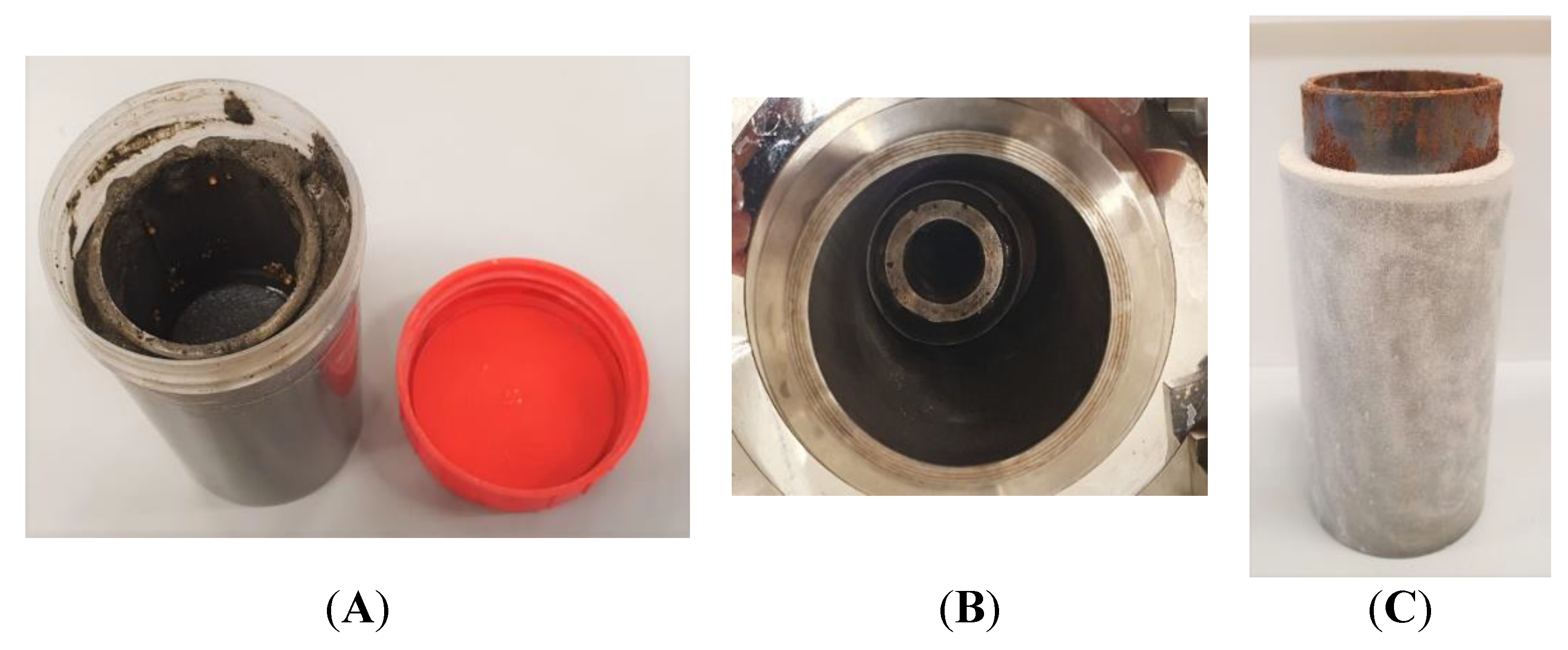
Figure 2.
A) close boxes for storage of samples under defined and controlled RH, B) samples inside of the box showing saturated salt solution for defining a controlled RH.
Figure 2.
A) close boxes for storage of samples under defined and controlled RH, B) samples inside of the box showing saturated salt solution for defining a controlled RH.
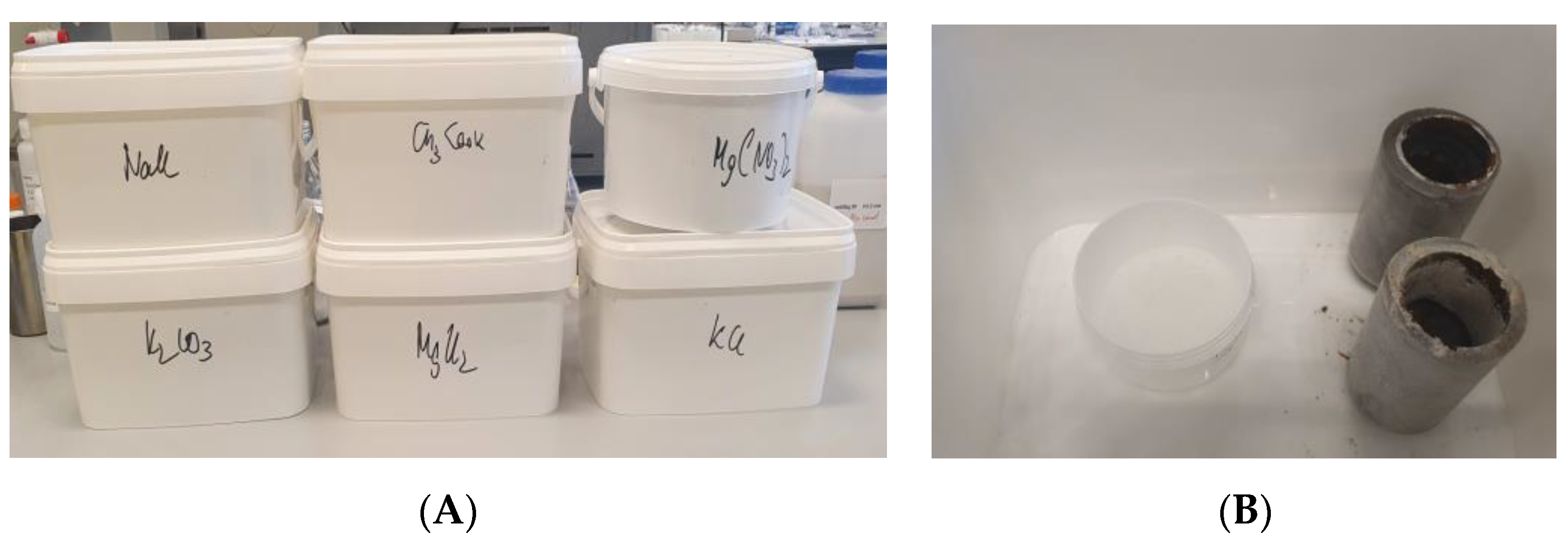
Figure 3.
Samples after 10 cycles of temperature cycling as retrieved from the autoclaves.
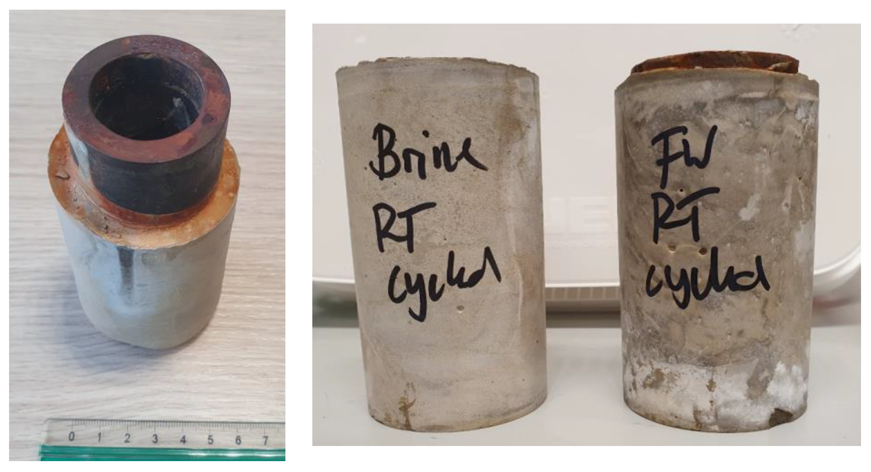
Figure 4.
A) Sample TestCEM B after thermal cycling and ageing in air showing radial cracking, B) acoustic scan beneath the outer surface of the cracked sample TestCEM B and C) acoustic scan of the same sample at the cement- steel interface showing partial debonding and the formation of a micro-annulus.
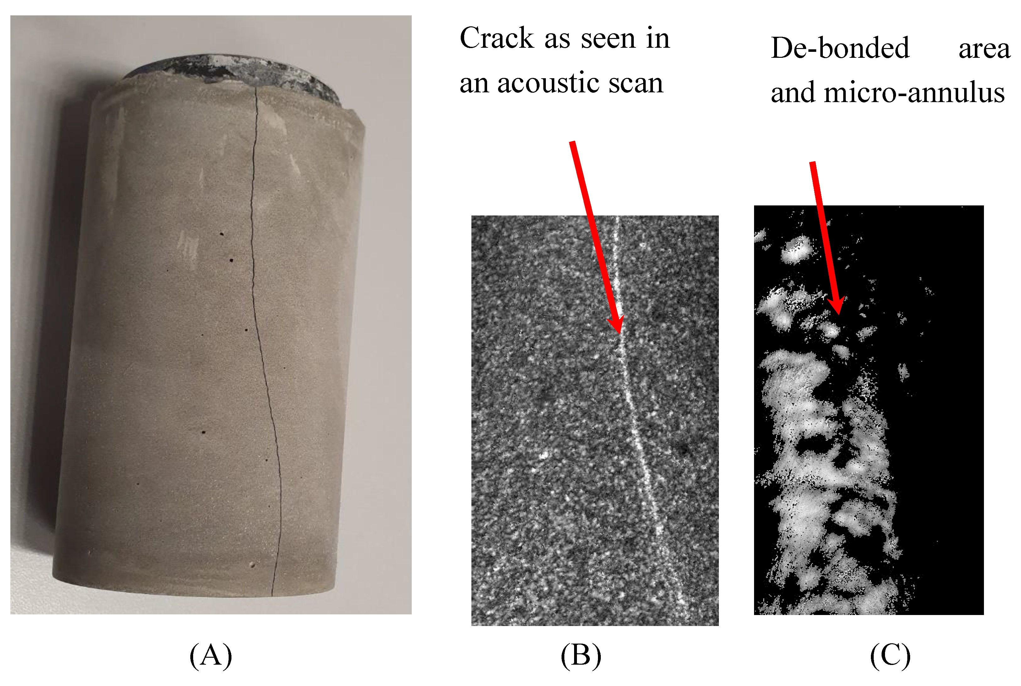
Figure 5.
A) TestCEM B sample after thermal cycling and ageing in air after total debonding of the cement-steel interface showing complete separation of cement and steel pipes without destruction of the cement part.
Figure 5.
A) TestCEM B sample after thermal cycling and ageing in air after total debonding of the cement-steel interface showing complete separation of cement and steel pipes without destruction of the cement part.
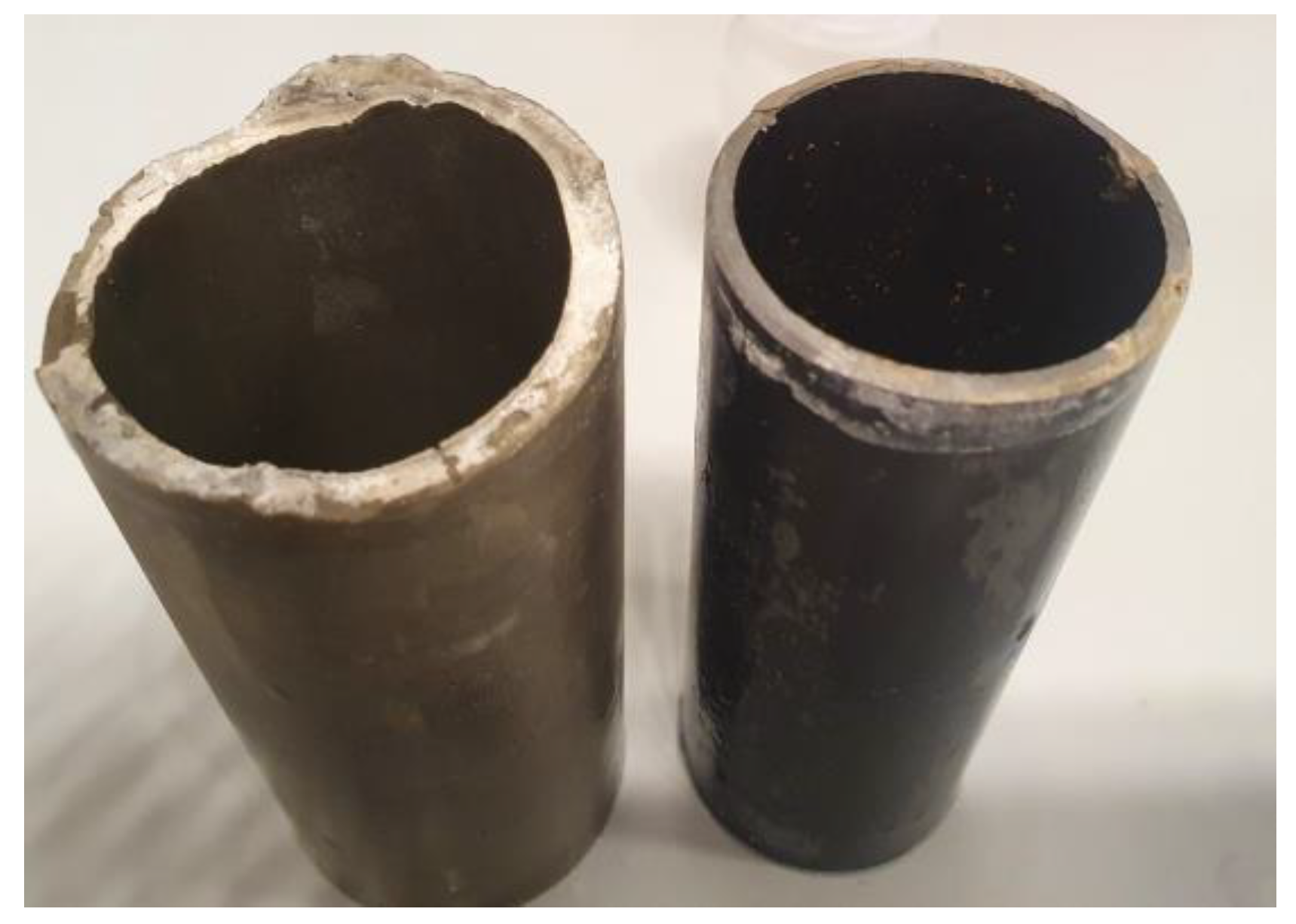
Figure 6.
Crack openings of the samples TestCEM B (A) and TestCEM si35 (B) after storage under 43 % RH.
Figure 6.
Crack openings of the samples TestCEM B (A) and TestCEM si35 (B) after storage under 43 % RH.
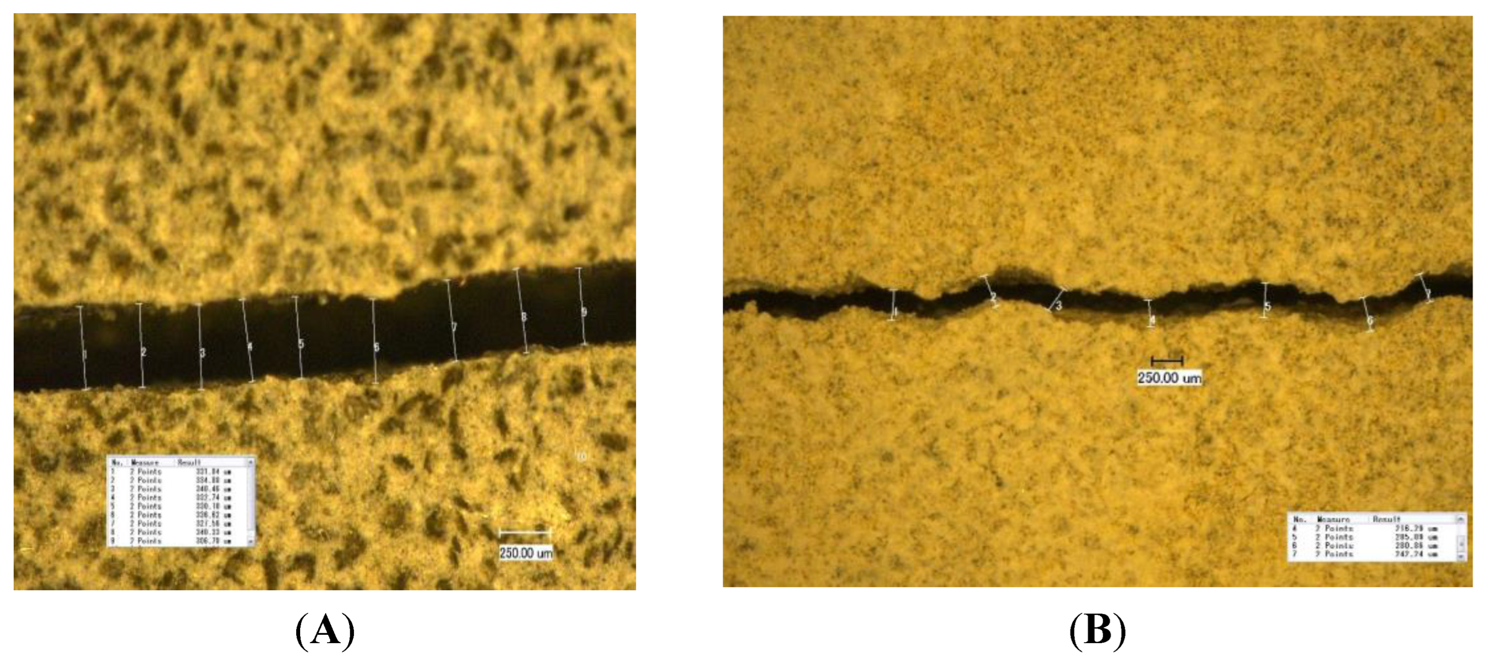
Figure 7.
Crack opening (width) in dependency on storage RH.
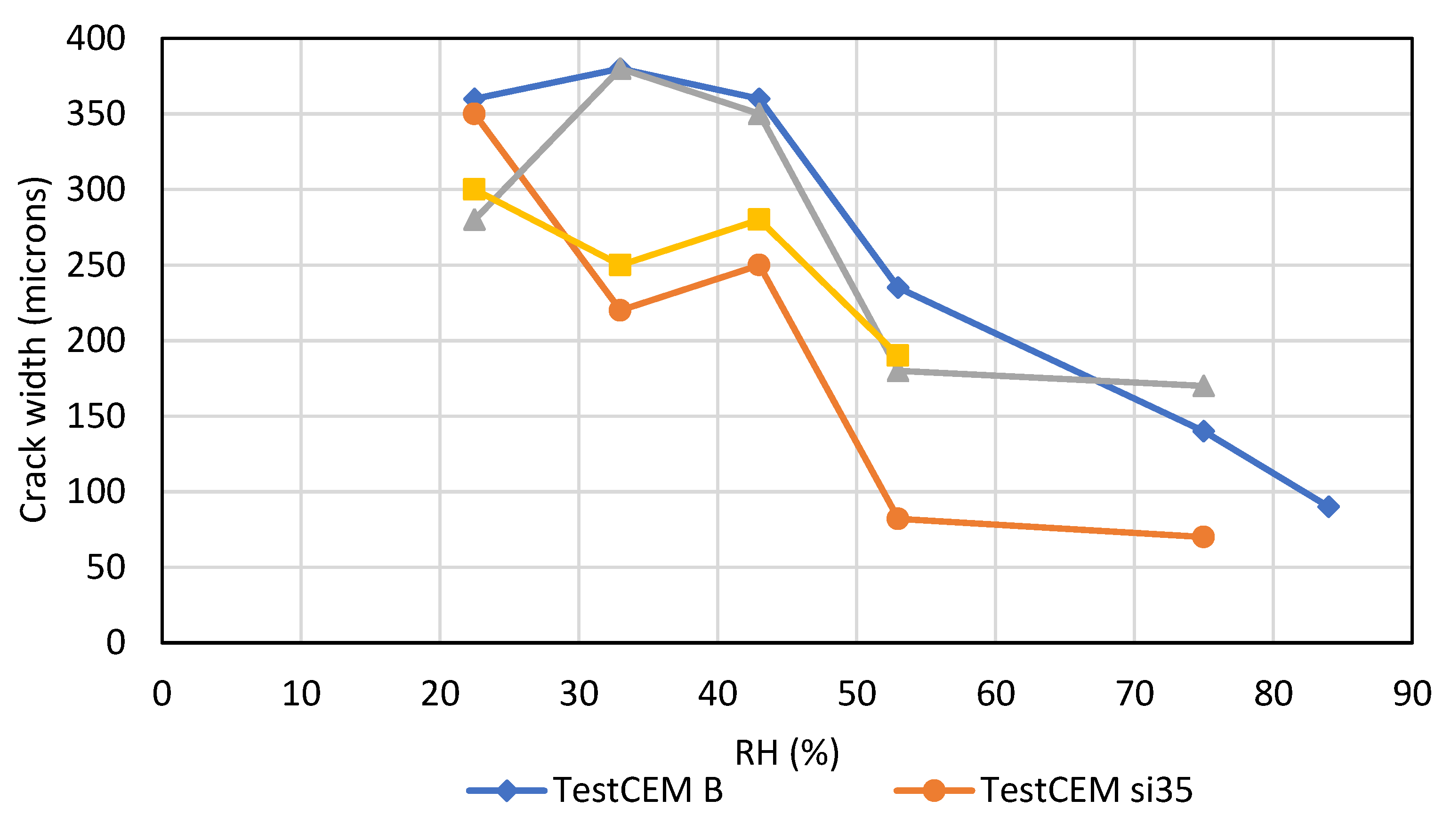
Figure 8.
Crack opening (width) time to crack appearance in dependency on storage RH.
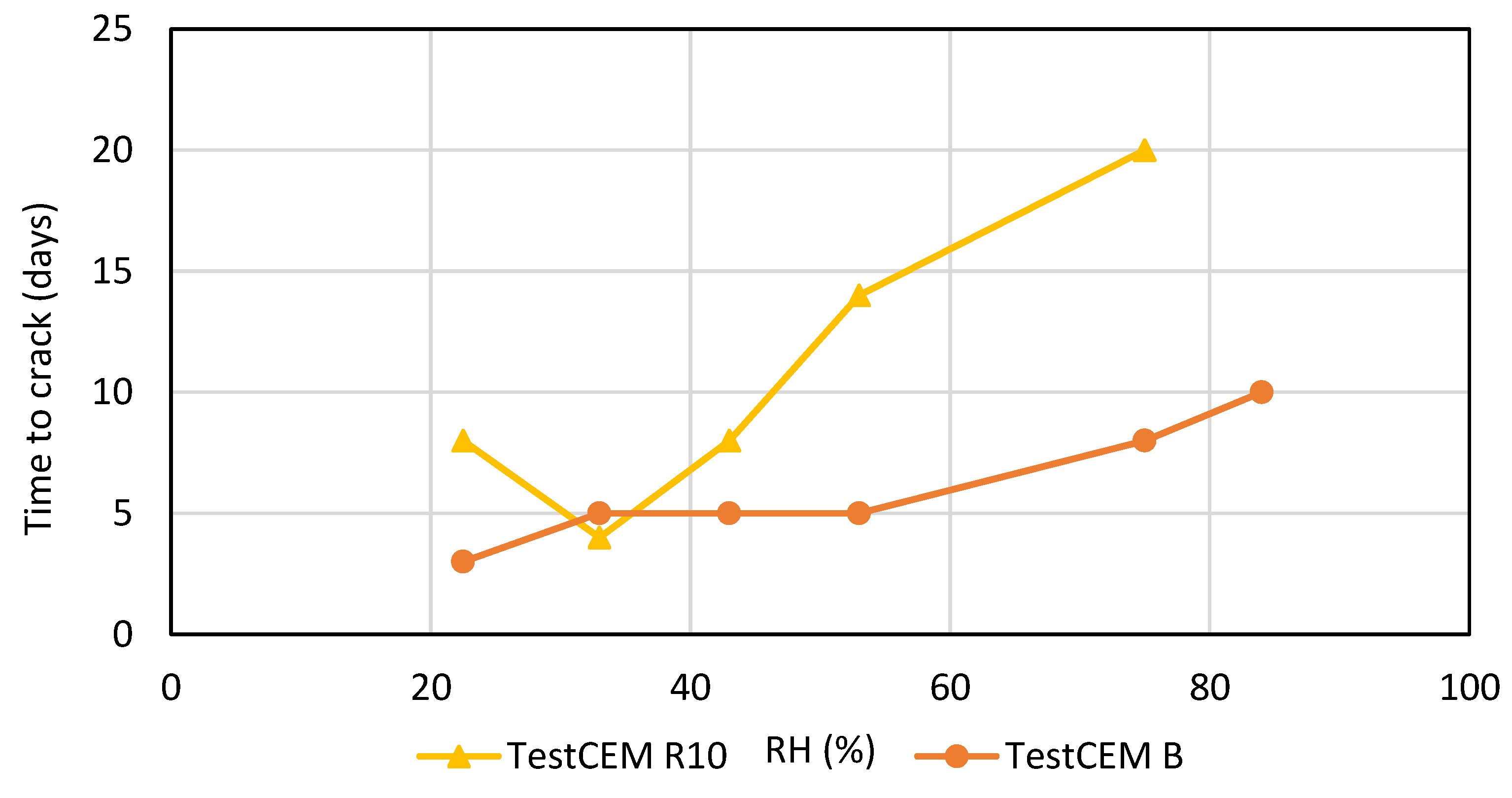
Figure 9.
Crack openings of the samples TestCEM PP (A) and TestCEM PAN-R10 (B) after storage under 43 % RH.
Figure 9.
Crack openings of the samples TestCEM PP (A) and TestCEM PAN-R10 (B) after storage under 43 % RH.
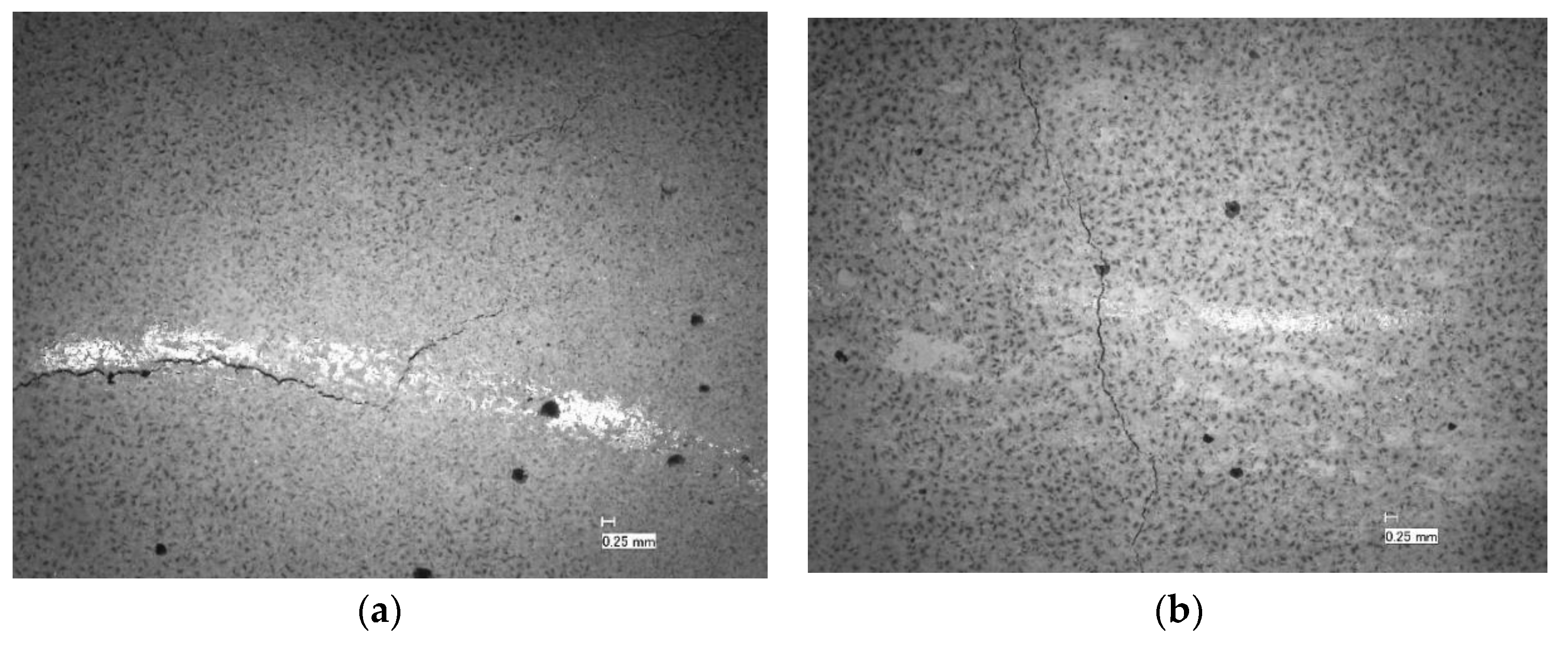
Figure 10.
Microscopic pictures of the morphology of the sample TestCEM PAN-BB showing the fine distributed PAN fibers embedded in the polymer latex film. Examples of the embedded fibres can be seen in the red circled areas.
Figure 10.
Microscopic pictures of the morphology of the sample TestCEM PAN-BB showing the fine distributed PAN fibers embedded in the polymer latex film. Examples of the embedded fibres can be seen in the red circled areas.
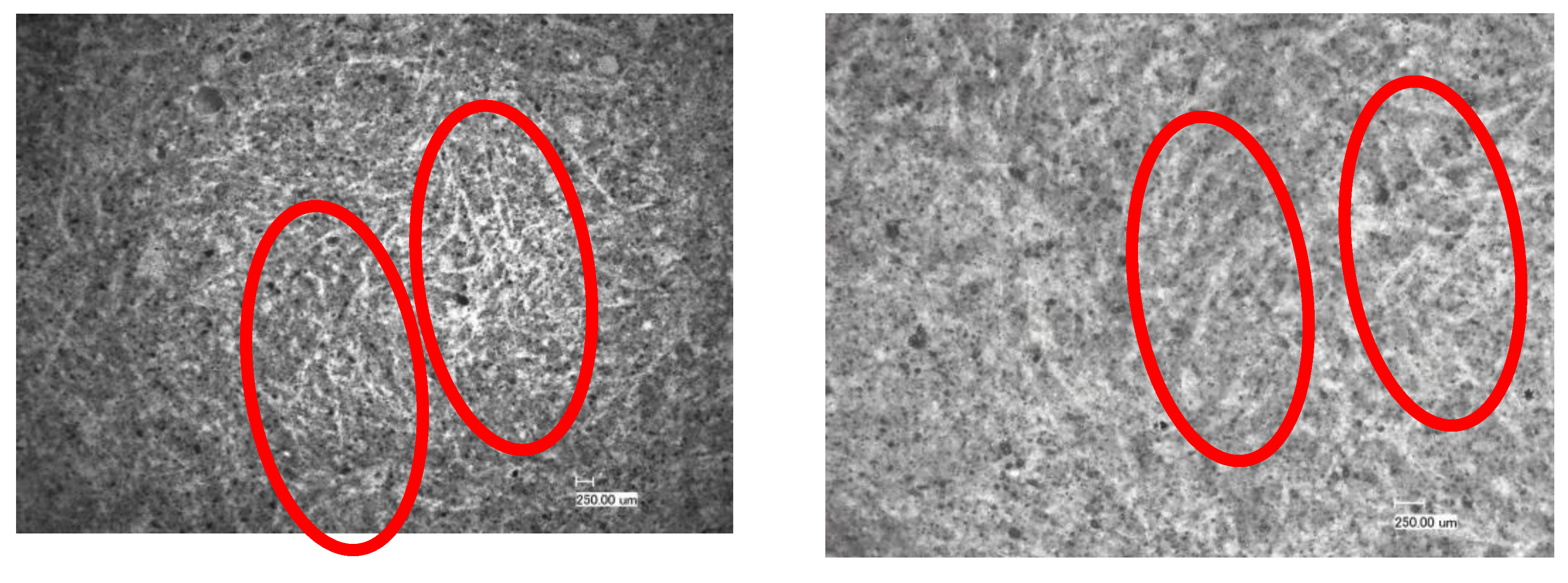
Figure 11.
Core samples of different cement formulations for validation of crack development under drying shrinkage.
Figure 11.
Core samples of different cement formulations for validation of crack development under drying shrinkage.
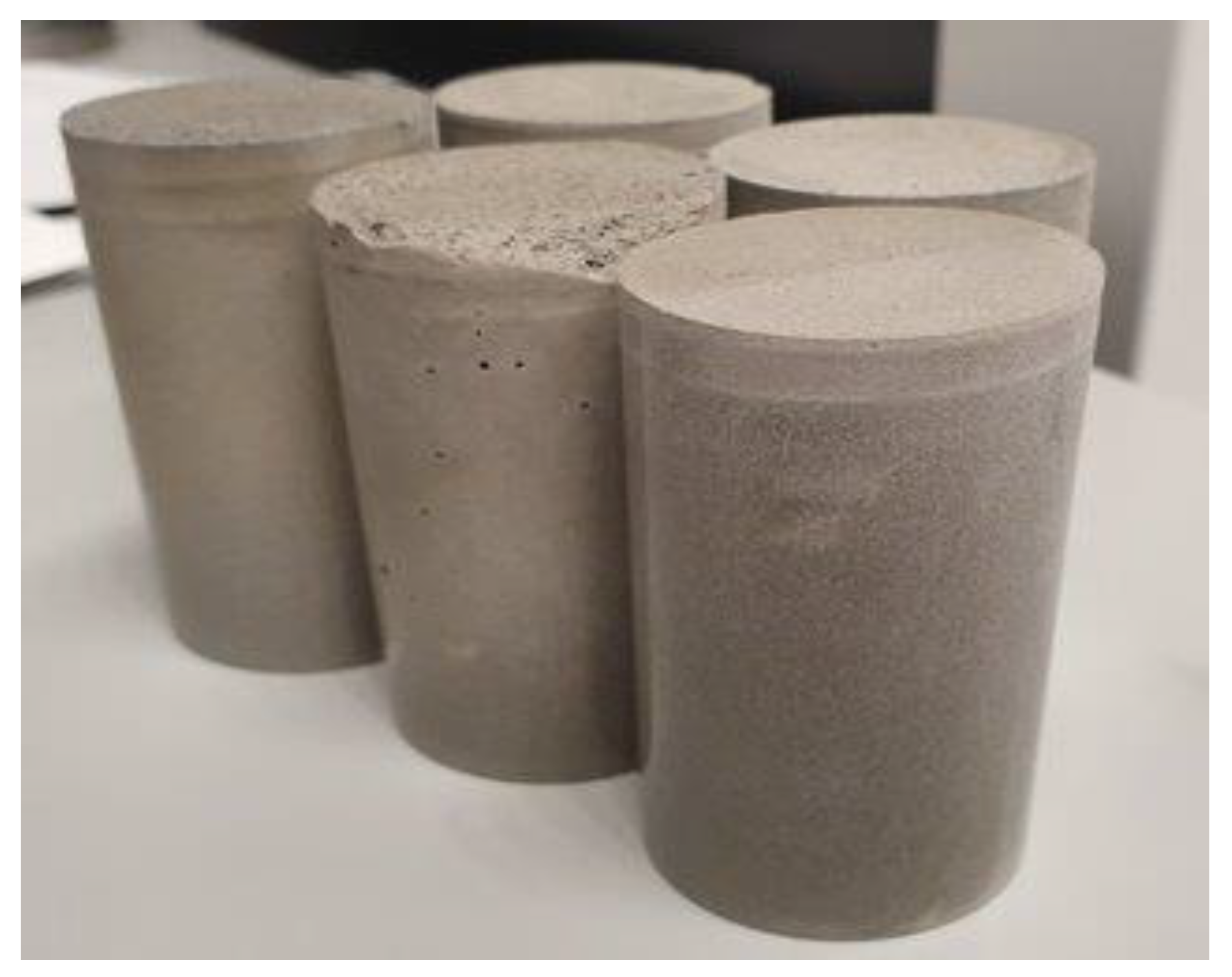
Figure 12.
Microscopic pictures of the cracks as developed in core samples of TestCEM B and TestCEM PG.
Figure 12.
Microscopic pictures of the cracks as developed in core samples of TestCEM B and TestCEM PG.
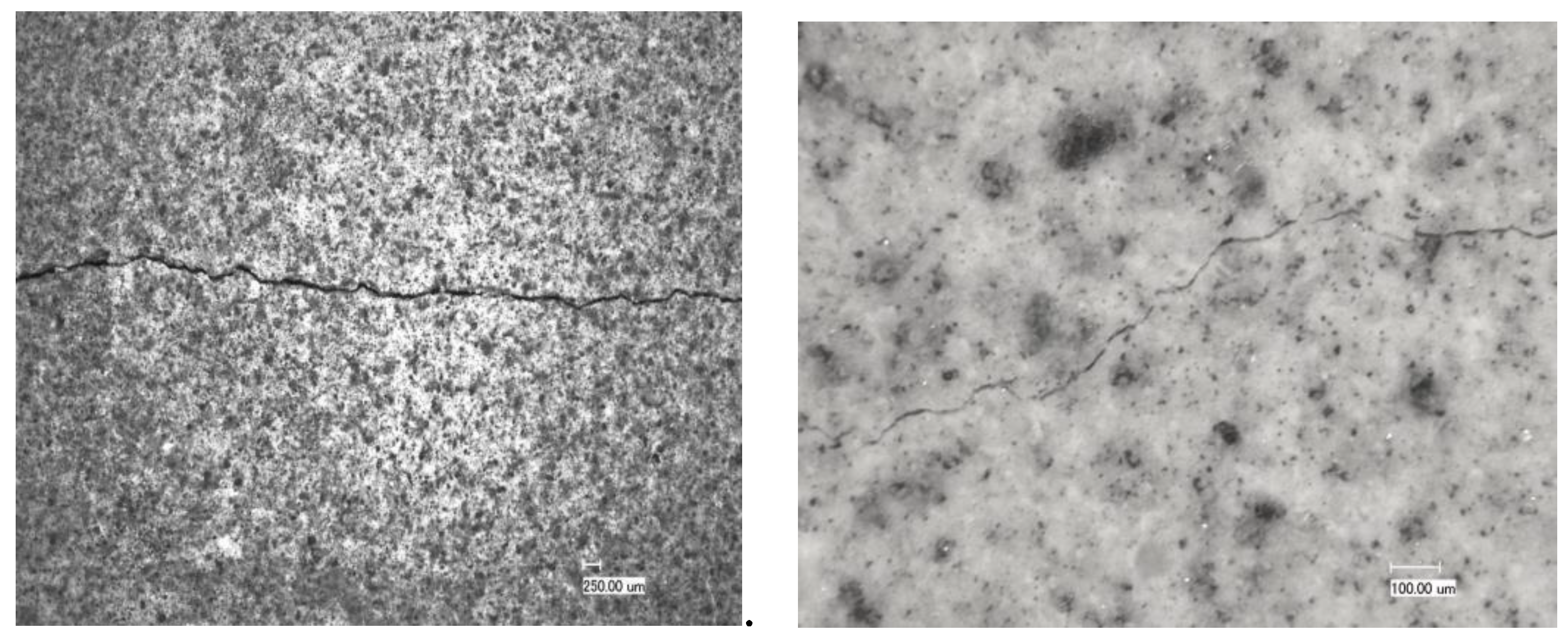
Figure 13.
CT scans of core samples of TestCEM B and TestCEM R20. Test CEM B clearly developed cracks throughout the whole sample. The TestCEM B sample shows also the presence of an interfacial transition zone (ITZ), a region of lower density which develops when cement hardens in contact with a solid wall. This ITZ is only less pronounced present in the TestCEM R20 sample.
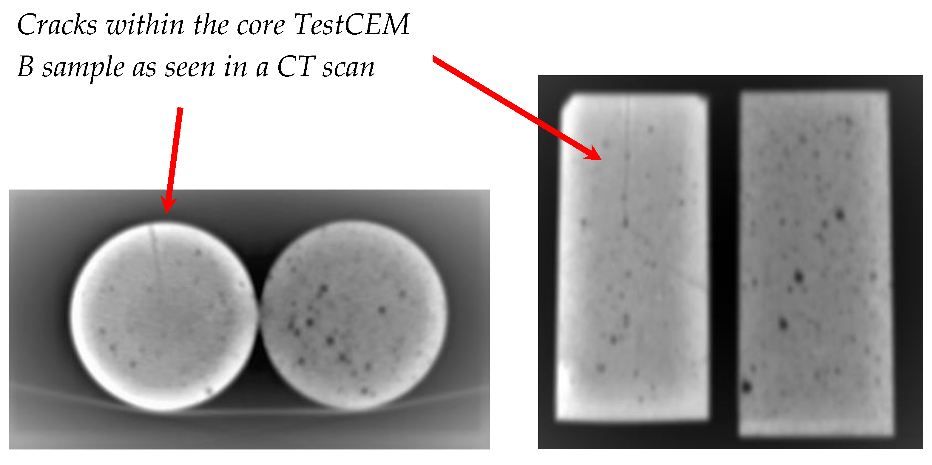
Figure 14.
Development of modulus as measured using micro indentation hardness of TestCEM samples in dependency of storage RH conditions.
Figure 14.
Development of modulus as measured using micro indentation hardness of TestCEM samples in dependency of storage RH conditions.
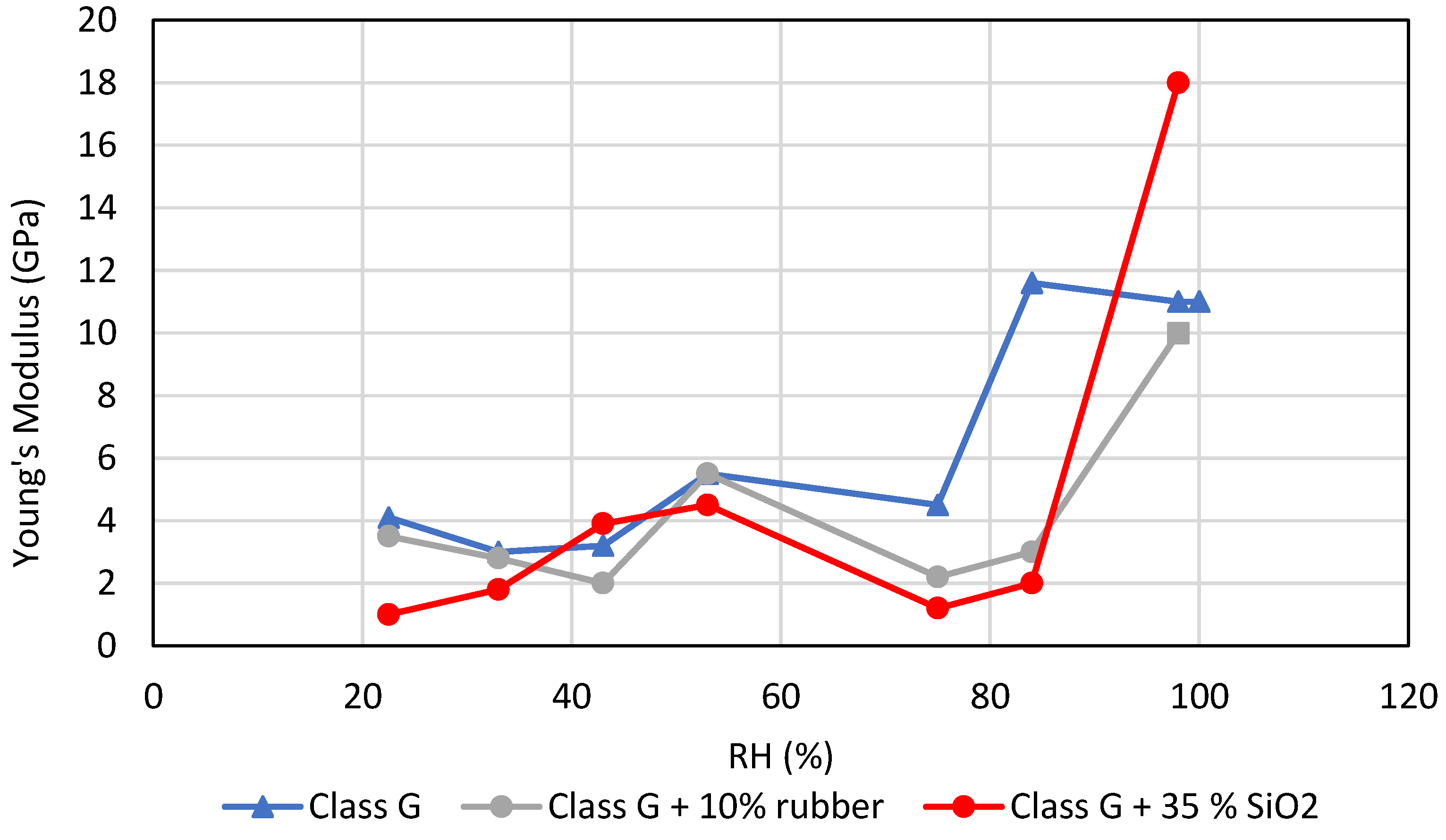
Figure 15.
SEM pictures of TestCEM B samples, A) cured under ambient conditions, B) cured under simulated well conditions (100 °C and 100 bar).
Figure 15.
SEM pictures of TestCEM B samples, A) cured under ambient conditions, B) cured under simulated well conditions (100 °C and 100 bar).
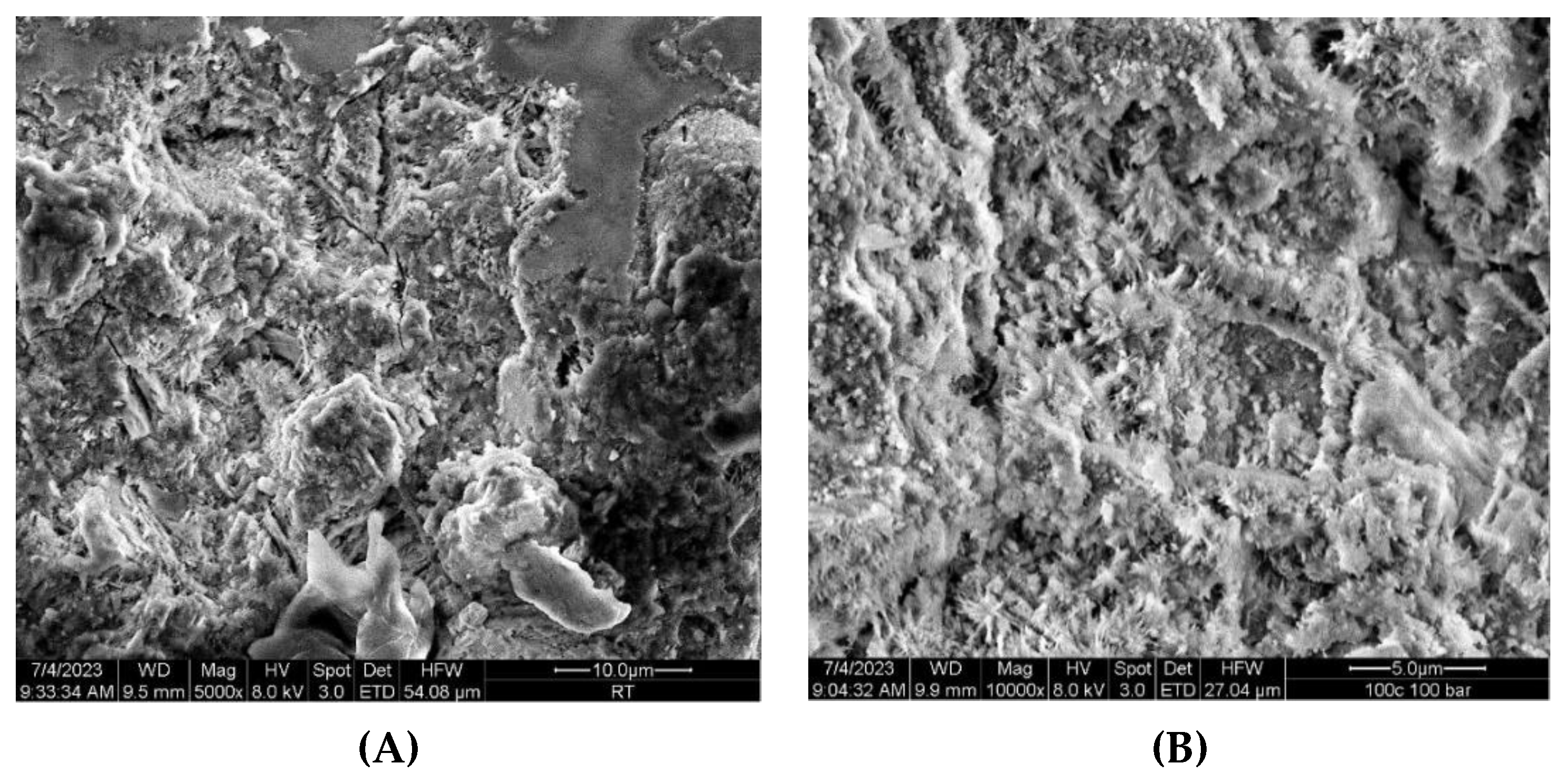
Figure 16.
Sandstone sample with steel casings embedded using TestCEM PP, TestCEM R10 and TestCEM R-BB formulations for curing and testing under simulated well conditions and thermal cycling.
Figure 16.
Sandstone sample with steel casings embedded using TestCEM PP, TestCEM R10 and TestCEM R-BB formulations for curing and testing under simulated well conditions and thermal cycling.
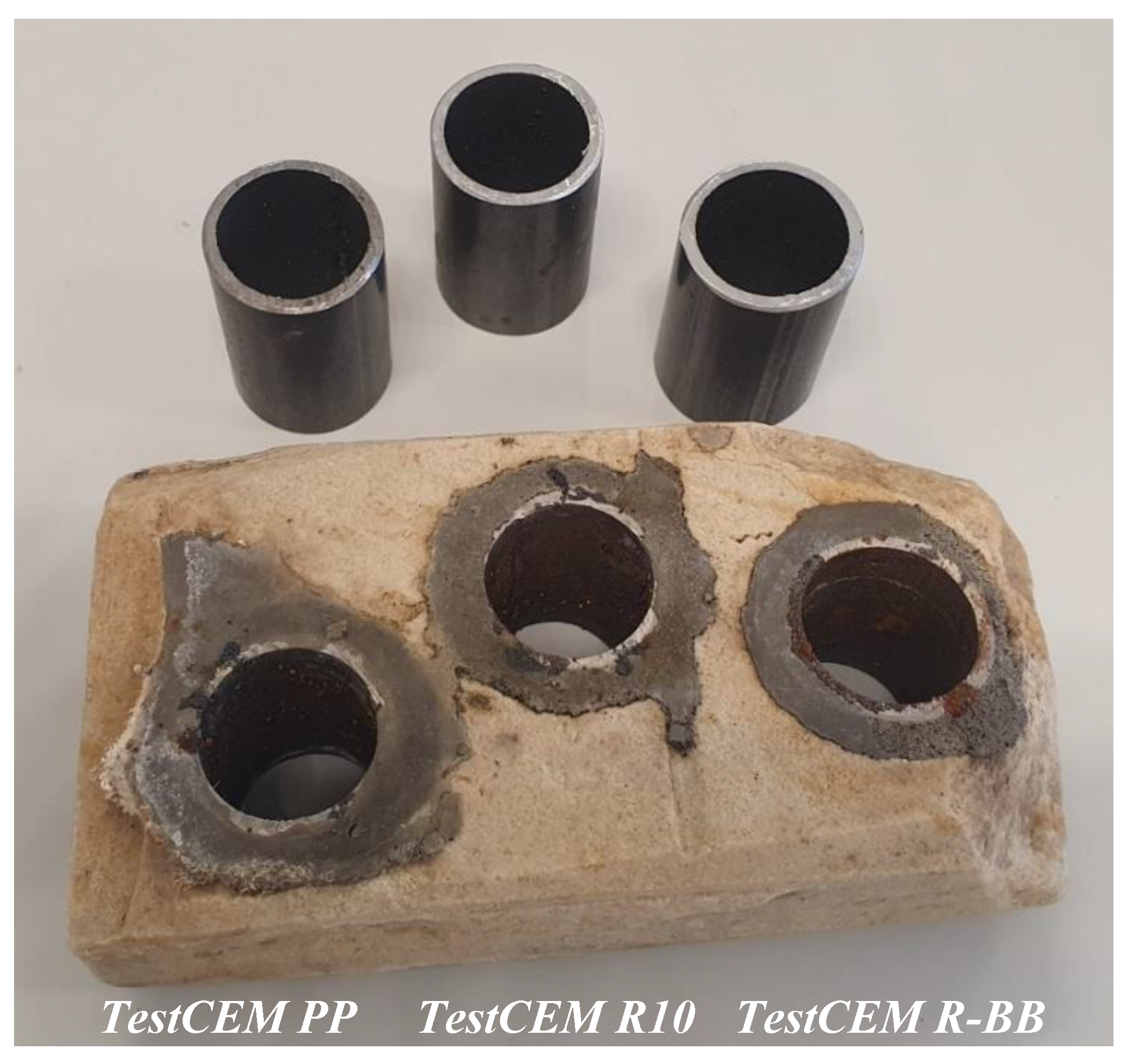
Figure 17.
Pictures of the TestCEM formulation-casing sample embedded in sandstone A) after curing and thermal cycling and B) after storage under RH of 50 %. All three samples show rust water droplets at the interface between steel casing and cement formulation indicating cement casing debonding.
Figure 17.
Pictures of the TestCEM formulation-casing sample embedded in sandstone A) after curing and thermal cycling and B) after storage under RH of 50 %. All three samples show rust water droplets at the interface between steel casing and cement formulation indicating cement casing debonding.
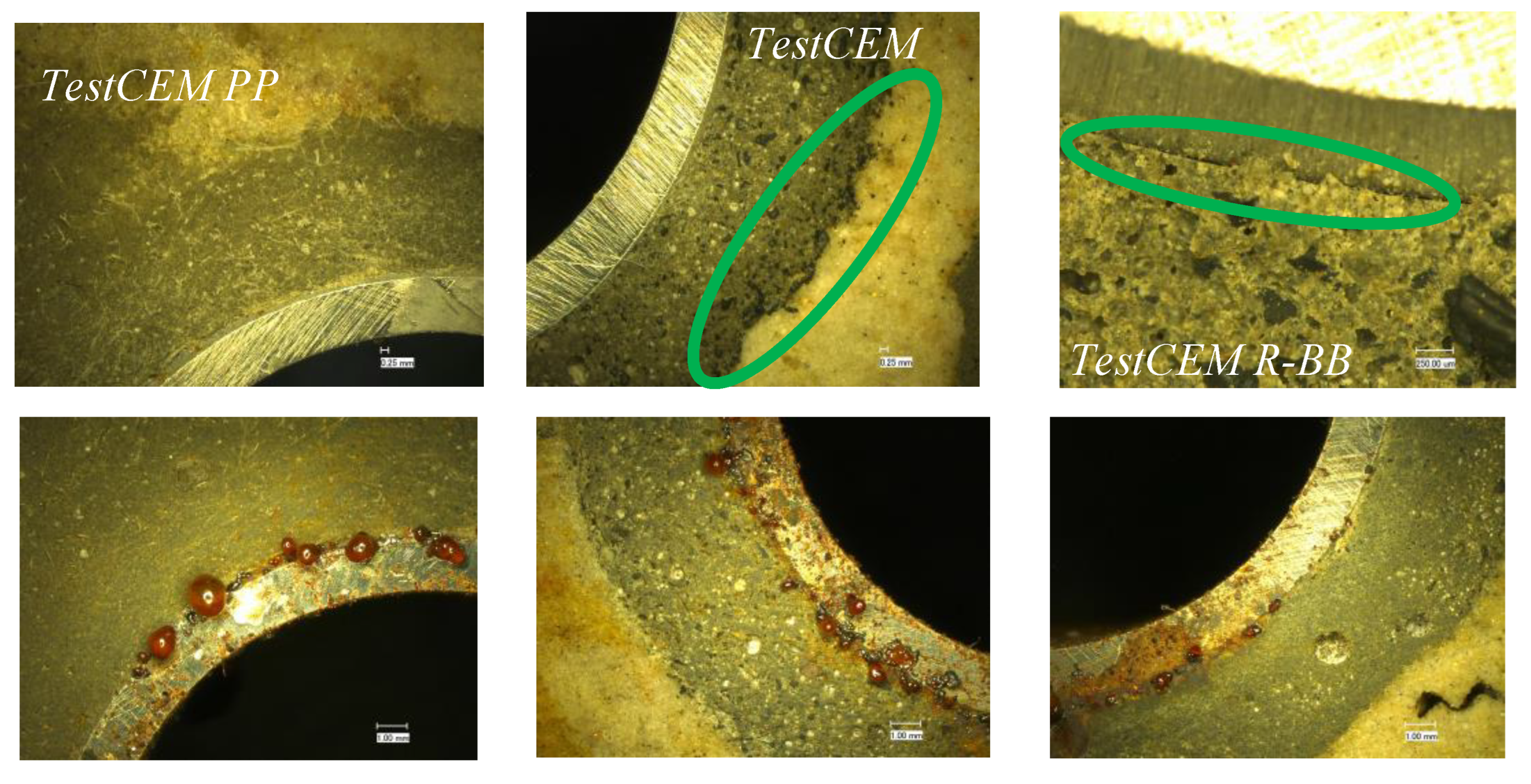
Figure 18.
Crack-bridging effect and fracture surface of a TestCEM formulation-core sample containing only 0.15% bwoc PP fibres after 3-point bending leading to fracture. Clearly, the fibres act like intended bridging the crack. The distribution of the fibres is very homogeneous ensuring the envisaged affect with a very small amount of fibres added.
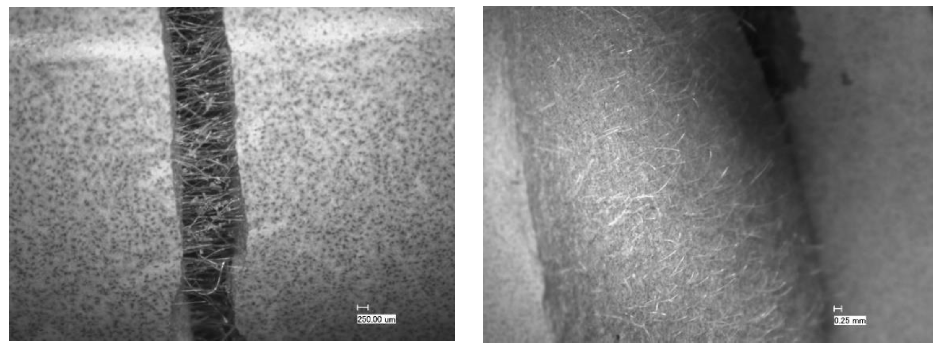
Figure 19.
Top and side view of the TestCEM PP core sample after compression strength testing. Again, the crack-bridging effect is very clear observable preventing the sample from complete disintegration and spalling.
Figure 19.
Top and side view of the TestCEM PP core sample after compression strength testing. Again, the crack-bridging effect is very clear observable preventing the sample from complete disintegration and spalling.
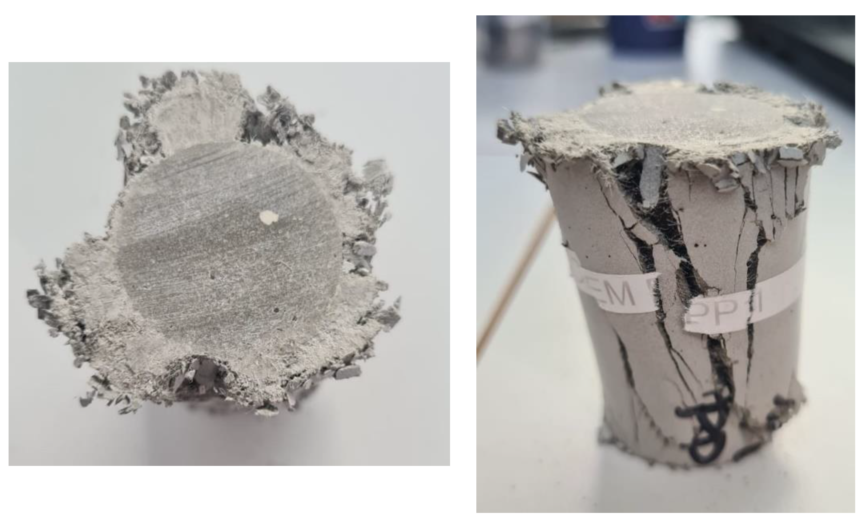

Table 1.
Overview of the prepared and tested samples (BWOC).
| Sample | Composition |
|---|---|
| TestCEM B | class G |
| TestCEM R10 | class G + 10 % rubber particles |
| TestCEM R20 | class G + 20 % rubber particle |
| TestCEM si35 | class G + 35 % silica fume |
| TestCEM si40 | class G + 40 % silica fume |
| TestCEM BB | class G + 10 % Basoblock |
| TestCEM PG | class G + 20 % Paragas |
| TestCEM PP | class G + 1.5 % PP fibers |
| TestCEM PAN | class G + 1.5 % PAN fibers |
| TestCEM Poz | 50 % class G + 25 % slag + 25 % pozzolan |
| TestCEM PAN-BB | class G + 1 % PAN fibers + 10 % Basoblock |
| TestCEM PAN-R10 | Class G + 1 % PAN fibers +10 % rubber particles |
| TestCEM R-BB | class G + 10 % rubber particles + 10 % Basoblock |
Table 2.
Salts used for preparation of saturated solutions with defined RH environment [16].
Table 2.
Salts used for preparation of saturated solutions with defined RH environment [16].
| Saturated Salt Solution | RH (%) |
|---|---|
| CH3COOK | 22.5 |
| MgCl2 | 33 |
| K2CO3 | 43 |
| Mg(NO3)2 | 53 |
| NaCl | 75 |
| KCl | 84 |
Table 3.
Crack openings developed in core samples.
| Sample | Crack Width Opening (μm) |
|---|---|
| TestCEM B | 45 |
| TestCEM si35 | 44 |
| TestCEM R10 | 35 |
| TestCEM R20 | - |
| TestCEM PG | 12 |
| TestCEM PP | - |
| TestCEM PAN | - |
| TestCEM PAN-BB | - |
| TestCEM PAN-R10 | - |
Disclaimer/Publisher’s Note: The statements, opinions and data contained in all publications are solely those of the individual author(s) and contributor(s) and not of MDPI and/or the editor(s). MDPI and/or the editor(s) disclaim responsibility for any injury to people or property resulting from any ideas, methods, instructions or products referred to in the content. |
© 2024 by the authors. Licensee MDPI, Basel, Switzerland. This article is an open access article distributed under the terms and conditions of the Creative Commons Attribution (CC BY) license (https://creativecommons.org/licenses/by/4.0/).
Copyright: This open access article is published under a Creative Commons CC BY 4.0 license, which permit the free download, distribution, and reuse, provided that the author and preprint are cited in any reuse.


