
Submitted:
19 October 2023
Posted:
19 October 2023
You are already at the latest version
Abstract
The magnetoelectric effect (ME) is an important strain mediated phenomenon in a ferromagnetic-piezoelectric composite for a variety of sensors and signal processing devices. A bias magnetic field, in general, is essential to realize a strong ME coupling in most composites. Magnetic phases with (i) high magnetostriction for strong piezomagnetic coupling and (ii) large anisotropy field that acts as a built-in bias field are preferred so that miniature, ME composite-based devices can operate without the need for an external magnetic field. We are able to realise such a magnetic phase with a composite of (i) barium hexaferrite (BaM) with high magnetocrystalline anisotropy field and (ii) nickel ferrite (NFO) with high magnetostriction. The BNx composites, with (1-x) wt.% of BaM and x wt.% NFO, for x = 0-100, were prepared. X-ray diffraction analysis shows that the composites did not contain any impurity phases. Scanning electron microscopy images revealed that with an increase in NFO content, hexagonal BaM grains become prominent, leading to a large anisotropy field. The NFO rich composites with x ≥60 show a large magnetostriction value of around -23 ppm, comparable to pure NFO. The anisotropy field HA of the composites, determined from ferromagnetic resonance (FMR) measurements, increased with increasing NFO content and reached a maximum of 12.39 kOe for x= 75. This large in-plane HA acted as a built-in field for strong ME effects under zero external bias in a bilayer with PZT. The BN composite was cut into rectangular platelets and bonded with PZT to form the bilayers. ME voltage coefficient (MEVC) measurements at low frequencies and at mechanical resonance showed strong coupling at zero bias for samples with x ≥33. The highest zero-bias MEVC of ~22 mV/cm Oe was obtained for BN75-PZT bilayers wherein BN75 also has the highest HA. Bilayer of BN41-PZT showed a amximum MEVC ~800 mV/cm Oe at electromechanical resonance at 68.4 kHz. The use of hexaferrite-spinel ferrite composite to achieve strong zero-bias ME coupling in bilayers with PZT is significant for applications related to energy harvesting, sensors, and high frequency devices.
Keywords:
Magnetoelectric
; ferrite
; ferroelectric
; magnetic anisotropy
1. Introduction
Multiferroic materials exhibit more than one ferroic order, such as ferromagnetism, ferroelectricity, and ferroelasticity [1]. They have recently attracted significant attention due to their potential for applications in spintronics, magnetoelectrics, nonvolatile memories, sensors, and electrically tunable magnetic microwave devices [2,3]. A ferromagnetic-ferroelectric composite is a multiferroic that shows a variation of its ferroelectric order parameters when subjected to an external magnetic field, direct magnetoelectric (ME) effect, or changes in magnetic parameters in an applied electric field, converse ME effect. [4]. In ME materials, the induced electric polarization P is related to the applied external magnetic field H by P = αH, where α is a second order ME-susceptibility tensor. Another parameter of importance is the ME voltage coefficient (MEVC) αE=δE/δH, which is related to α by α=ε0εrαE, where εr is the relative permittivity of the material. According models for the ME effects in single-phase materials, the upper bound α is limited to the relation α ≤ (με)1/2, where μ and ε are the permeability and permittivity of the material, respectively [5]. One of the known single-phase multiferroic with a large α at room temperature is BiFeO3 [6]. In composite ME materials, the α can be ehnaced by exploiting the strain mediated interactions between the two phases [4].
To obtain the maximum ME voltage coefficient (αE) in a ferromagnetic-ferroelectric composite an optimized magnitude of the DC magnetic bias field H is needed. A maximum in the αE occurs when the piezomagnetic coefficient q=dλ/dH (where λ is the magnetostriction) of ferro/ferrimagnetic component of the composite is also maximum. Hence a bias magnetic field, in general, is essential to achieve strong ME response. The need for a bias field, however, could be eliminated with a self-bias in the ferromagnetic. There are several avenues to accomplish the self-bias condition such as a large magneto-crystalline anisotropy field or the use of a functionally graded ferromagnet [7,8,9]. Other avenues include the use of compositionally graded ferromagnetic phase [10]. There are several experimental findings [11,12,13] and theoretical models [11,12,13] on graded ME composites. In laminated composites changing the mechanical resonance modes through electrical connectivity evoke the zero bias coupling when the bending strain activates a built-in bias [9]. Thin films that rely on magnetic field dependence of resonant frequency and angular dependence of exchange bias field [14,15] can also show zero-bias ME effect. It is also shown that a homogeneous magnetostrictive phase can also produce zero bias ME effect [16]. Cofired layered composites consisting of textured Pb(Mg1/3Nb2/3)O3-PbTiO3 and Cu and Zn doped NiFe2O4 show a giant zero-bias ME coefficient ~1000 mV/cm Oe [17] wherein built in stress induces zero-bias effect.
Here we discuss a novel approach for a self-biased ME composite with the use of a ferromagnetic layer consisting of both M-type barium ferrite hexagonal ferrite, BaO 6Fe2O3 (BaM), with uniaxial anisotropy on the order of ~ 17.4 kOe, and nickel ferrite NiFe2O4 with high magnetostriction and piezomagnetic coefficient q [18]. Composites of BaM-NFO with (1-x) wt.% of BaM and x wt.% of NFO, (BNx), were prepared by sintering powders of both ferrites. X-ray diffraction revealed the presence of both BaM and NFO and the absence of impurity phases. Scanning electron microscopy images showed crystallites of both ferrites. Magnetostriction λ measurements for BNx indicated values increased with increasing x and for x > 65 reached values comparable that of pure NFO. High frequency measurements were carried out to determine the anisotropy field HA from dependence of the ferromagnetic resonance (FMR) frequency fr on static magnetic field H. The in-plane HA values in BNx were found to well above the value of 500 Oe for pure NFO. Platelets of sintered BNx were bonded to PZT to form bilayers for ME voltage coefficient (MEVC) measurements that showed a significant zero-field ME effects. Details on results of the studies are provided in the following sections.
2. Experiment
Micrometer sized polycrystalline powders of NFO and BaM were synthesized separately using conventional ceramic processing techniques. High purity NiO, BaCO3, and Fe2O3 were mixed and ballmilled for 8 h. The powders were dried and pre-sintered at 900 ºC for 6 h. The pre-sintered powders were ballmilled again and then sintered at 1200 ºC for 6 h. Composites of (1-x) wt.% BaM- x wt% NFO (BNx) (x=5, 9, 13, 33, 38, 41, 44, 47, 60, 75, 85 and 95) were prepared by mixing the ferrite powders. A binder, 2% PVA, was added to the powder and pressed into disks (dia~18 mm and thickness ~2 mm) by applying uniaxial pressure of 250 MPa. The disks of BNx were finally sintered at 1250 ºC for 6 h.
The crystal structure of the composites was characterized by a powder X-ray diffractometer (Miniflex, Rigaku) at room temperature. Morphological features of the samples were studied with an SEM (JSM-6510/GS, JEOL). Magnetostriction of the composite materials were investigated using a strain gage and a strain indicator/recorder (P3, Micro-Measurements). Magnetization at room temperature as a function of H was measured with a Faraday susceptibility balance. Ferromagnetic resonance (FMR) measurements were done with the sample placed on a coplanar waveguide and with the magnetic field H parallel to the sample plane. A vector network analyzer (Agilent) was used to record profiles of the scattering matrix S21 vs frequency f for a series of H. Measurements of ME coupling strengths were done on bilayer of BNx and vendor supplied PZT that was bonded with a thin layer of epoxy. The ME voltage coefficient (MEVC) measurements were done by subjecting the bilayer to an ac magnetic field Hac and a bias field H. Both H- and f-dependence of the MEVC were measured for both the magnetic fields parallel each other and either parallel or perpendicular to the sample plane.
3. Results
Representative powder X-ray diffraction (XRD) patterns of the BNx samples are shown in Figure 1. XRD patterns other BNx compositions are shown in the Figure S-1 in the Supplement. The XRD patterns show diffraction peaks from NFO and BaM. With increasing x-values, the NFO lines become stronger and BaM lines get weaker as expected. A small amount of an impurity phase, identified as antiferromagnetic Ba5Fe2O8, is present only in BN41, BN44 and BN75 [19]. Usually, Ba5Fe2O8 type impurities (5BaO+Fe2O3) occur during the sintering of BaO and Fe2O3 based ferrites, especially in BaFe12O19 [19]. However, since Ba5Fe2O8 is AFM, the overall ME character of the BNx-PZT bilayers is expected to be unaffected.
Representative SEM images for BNx (x=5, 33, 60 and 95) are shown in Figure 2. The gradual increase in the grain size in the BN composites with increasing x (also in Supplementary Figure S2) may indicate that NFO aids in the growth of hexagonal BaM grains for x≥9. Large grains are absent in BN5, but a closer examination of the surface morphology shows hexagonal-like features with grain size <2 μm. With increasing NFO content grains with size larger than 5 μm are present. For x > 41, the number of large grains reduces again. For the highest content of NFO (BN95) we observe similar grain distribution as pure NFO (Supplementary Figure S2). BN5 also shows a similar grain distribution as pure BaM. Barium ferrite itself tends to form hexagonal grains [20] and with a tweak in the synthesis process the particle shape can be made perfect spherical [21]. In our case the processing has a large impact on the grain growth on these composites. The stabilization of the typical hexagonal BaM grains amongst NFO particles is worth noting.
Since the magnetostriction λ is one of the key parameters that determine the strength ME interaction, we measured its value for the BNx composites. The measurements were done with a strain gage and a strain indicator and for H applied parallel to the sample plane. Data on the magnetostriction λ11 measured parallel to H for the composites are shown in Figure 3. The samples exhibit negative values for λ11. The results are in accordance with the nature of magnetostrictive response of BaM and NFO [22,23]. With increase in the NFO content λ11 increases and tends to show similar behaviour as pure NFO (shown in the inset of Figure 3). The highest value of λ11 ~ -23 ppm was measured for BN60 and we got similar values for x≥60. Our measurements on pure BaM showed λ11=-1 ppm at 2.7 kOe. Hence it is clear that NFO phase is the major contributor towards the net magnetostriction of BN composites.
A key objective in this work is to achieve large enough HA values in BNx to realize a strong zero-bias ME effects in a composite with PZT. Ferromagnetic resonance studies were carried out on the composites to determine HA. Ferrite platelets, rectangular in shape, were placed in an S-shaped coplanar waveguide and excited with microwave power from a VNA. Profiles of the scattering matrix S21 as a function of frequency f were recorded. Figure 4 shows such profiles for a series of in-plane static magnetic field H along the sample length. For x values < 10, a single resonance mode was seen in the 50 GHz range (See Supplementary Figure S3). With increasing NFO content two resonance modes were seen as in Figure 4, one in the frequency range 3-20 GHz and another in the range 40-60 GHz. As discussed next, the resonance mode at the low frequency region in Figure 4 is due to FMR in NFO whereas the higher frequency resonance is a magneto-dielectric mode in the composite [24].
The H-dependence of the low- and high frequency mode frequencies fr are shown in Figure 5 (and in Supplementary Figure S4). Data on fr vs H for the low-frequency mode is shown in Figure 5(a) for BN33 and BN60, with fr increasing from 7.5 GHz at H= 1 kOe to 16 GHz for H=3.5 kOe for BN60 which amounts to an increase in fr with H at the rate 3.4 GHz/kOe. A similar rapid increase in fr with H is seen in Figure 5(a) for BN33. From the rate of change in fr with H one may associate this mode with FMR in NFO. Data in Figure 5(b) on fr vs H for the high frequency mode are for BN33 and BN60. This mode shows a linear variation in fr with H with a rate of increase ~1.3 GHz/kOe. This slow variation in fr with H is indicative of a magneto-dielectric mode in the composite platelet. This mode is not of importance for the current study and is considered for further analysis [24].
In order to estimate the built-in magnetic anisotropy field HA in the composites, we first analysed the fr vs H data for FMR as shown in Figure 6 to determine the effective magnetization 4πMeff= 4πMs + HA, where 4πMs is the saturation magnetization. The Kittel equation for the FMR mode frequency is given by,
where, γ is the gyromagnetic ratio, H is the in-plane external magnetic field along the x-direction, Nx, Ny and Nz are the demagnetization factors along the length, width and thickness of the platelet, respectively. The demagnetizing factors were calculated for the platelets used for FMR and the data as in Figure 6 was fitted to Eq. (1) to determine 4πMeff. Estimated values of the gyromagnetic ratio γ and 4πMeff and measured 4πMs are given in Table 1. The values of γ range from 3.17 GHz/kOe for x = 33 to 2.98 GHz/kOe for x = 0.75 that are well within the range 3.20 GHz/kOe for pure NFO to 2.69 GHz/kOe for polycrystalline BaM [25,26]. The cause of low γ value for x = 75 needs to be investigated. Values of the anisotropy HA estimated from FMR data are also given in Table 1 for BNx composites with x = 33 – 95. The anisotropy field HA is negative for x = 33 and 38, indicative of out-of-plane anisotropy for the polycrystalline composites. It is positive for higher x-values, increases from ~ 1 kOe for x=41 to ~ 12.39 kOe for x=75. Further increase in x results in a decrease in HA. One may therefore infer from these HA -values that a majority of BaM crystallites in x = 33 and 38 have out-of-plane orientation leading to a rather small perpendicular anisotropy for the sample. With increasing value of NFO content in x > 41, the higher concentration of NFO appears to promote the growth of BaM crystallites with in-plane orientation for the c-axis and a net in-plane anisotropy field that reaches a maximum value for x = 75. Several reported efforts in the past on FMR in polycrystalline BaM mainly dealt with textured BaM thin and thick films and showed, depending on the degree of texture, out-of-plane HA -values in the range 4.5 to 15 kOe [27,28]. In this work, however, the composites show in-plane anisotropy field except for x = 33 and 38.
The strength of ME coupling was measured in bilayers of the composites and vendor supplied PZT (PZT850, American Piezo Ceramics, USA). Ferrite platelets of approximate lateral dimensions 5 mm × 10 mm and thickness t = 0.3 – 0.5 mm were bonded to PZT with 20 μm thick layer of a fast-dry epoxy. The ME voltage coefficient (MEVC) was measured for two different orientations of the applied magnetic fields: (i) α31 for the DC filed H and ac field h both parallel to each other and along the length of the sample and (ii) α33 for the magnetic fields applied perpendicular to the sample plane. The MEVC is given by α = V3/(h t), where V3 is the strain induced ac voltage measured across PZT. The ME coefficients were measured at low frequencies as well as at mechanical resonances in the bilayers.
Figure 7 (and Figure S5 in the supplement) shows the H dependence of α31 for ac field h at 100 Hz. The MEVC is directly proportional to the piezomagnetic coupling q = dλ/dH.
The value of α31 increases with increase in H to a maximum. The maximum value of MEVC for BN5 is rather small due to low q-value for this BaM rich composite. With further increase in the NFO content in the composites, α31 increases to a maximum value of ~ 152 mV/cm Oe for BN95. Upon further increase in H, α31 in general decreases to a minimum for composites with x > 5. Bias field H dependence of α31 in Figure 7 essentially tracks the variation in q with H, reaches a maximum at the maximum in the slope of λ11 vs H, and drops to near zero when α31 vs H (Figure 3) shows saturation. Other significant features in the results from Figure 7 are as follows. (i) When H is decreased from ~ 3 kOe back to zero a hysteresis in α31 vs H is evident for all the BNx-PZT bilayers. (ii) Upon reversing the field H, a 180 deg phase shift (indicated by negative values for α31) is observed in the ME voltage except for x=5. (iii) The bilayers show a finite remnant value for α31 at zero-bias and, as discussed later, is attributed to the built-in bias in BNx provided by the anisotropy field HA.
Figure 8 shows results of MEVC measurements for the magnetic fields applied perpendicular to the bilayers of BNx-PZT (also shown in the supplement, Figure S5). The variation in MEVC has similar hysteresis and remnance as for the in-plane magnetic fields.
However, the following features in α33 vs H differ from the dependence of MEVC for in-plane magnetic fields. (i) Overall MEVC values are smaller in Figure 8 since demagnetization factors reduce both the dc and ac magnetic fields. (ii) the decrease in MEVC for H > 1.5 kOe is relatively small compared to α31 vs H. (iii) Data in Figure 8 for BN95-PZT bilayers shows a reversal in the sign of for H > 0.75 kOe for both positive and negative H.
The strength of ME coupling in the bilayers was also characterized by measuring the frequency f dependence of the MEVC at mechanical resonance modes. Prior to these measurements we obtained the electromechanical resonance (EMR) frequencies (fr) for the composites by measuring the frequency dependence of the impedance with an LCR meter. Mode frequencies could not be obtained for BNx for x≤19, but we were able to determine the frequency of longitudinal resonance modes for higher x-values. MEVC α31vs f under a bias field H =100 – 200 Oe for the bilayers are shown in Figure 9. One observes an increase in α31 with increasing f and a sharp peak in its value at fr ~ 66 – 73 kHz. We were able to identify fr with the longitudinal EMR mode from the known composite dimensions. For x=33 the figure shows a fine structure with a double peak in the α31vs f profile with values of 147 mV/cm Oe at 72.9 kHz and 132 mV/cm Oe at 73.2 kHz. Bilayers of BNx-PZT with x>33 have a single peak in the profiles and BN41-PZT shows the highest value of α31=797 mVcm-1Oe-1 at 68.4 kHz. One observes a significant enhancement in the ME coefficients at fr compared to values at 100 Hz (Figure 7), and for example, by a factor 36 for x=41. We discuss the results of these ME measurements in the following section.
4. Discussions
It is evident from the results of this study that (i) it is possible to synthesize composites of spinel and M-type hexagonal ferrites free of ferromagnetic impurity phases, (ii) the composites, depending on the amount of BaM, have a moderately high uniaxial anisotropy that switches from uniaxial in BaM-rich compositions to planar anisotropy as NFO content is increased, and (iii) the magnetostriction is quiet small for BaM rich composites, but increases significantly with increasing NFO content although the piezomagnetic coefficient q is rather small in all of the composites due to slow increase in λ with H compared to pure NFO.
It is clear from the results of ME measurements in Figure 7, Figure 8 and Figure 9 that the bilayers of BNx and PZT show MEVC that are much higher than reported values for M-type hexaferrite-PZT bilayers [29], but smaller than for NFO-PZT [30]. Under optimum value of H, the highest MEVC are α31 = 152 mV/cm Oe and α33 = 90 mV/cm Oe, both for BN95-PZT. These values, however, are relatively small due to the weak piezomagnetic coupling strengths in BNx compared to nickel ferrite or nickel zinc ferrite based layered composites with PZT [30,31].
A key and primary objective of this work was to synthesize a ferromagnetic oxide with a moderately large HA and high magnetostriction and piezomagnetic coupling for use with PZT to achieve ME coupling in the absence of an external bias magnetic field. It is worth noting that this goal was indeed accomplished. Bilayers of BNx-PZT used in this study do show a zero-bias MEVC (Figure S6 in the supplement). Bilayer of BN75-PZT shows the highest α31=22 mV/cm Oe at zero bias and BN85-PZT bilayer shows highest α33=9 mV/cm Oe at zero bias. Strategies employed in the past to realize zero-bias ME effects included the use of an external stimuli or a ferromagnetic layer graded either in magnetization or in composition, etc [7,8,9,10,11,12,13,14,15,16,17]. The use of an easy to synthesize composite of a spinel ferrite and hexaferrite in this work for zero-bias ME effect makes this method more viable than others. There are reports wherein composites consisting of NFO and PZT show large ME coefficient of 460 mV/cm Oe for bilayers and 1500 mV/cm Oe for multilayers [32]. The MEVC at resonance in these systems was as high as 1 V/cm Oe [33]. Modified NFO and PZT multilayers even showed a higher ME coefficient [34]. But there is hardly any evidence for ME coupling zero-bias effect in these composites [29,30,31,32,33,34,35].
Due to very low magnetostriction BaM is not suitable for strong direct ME coupling, but the very high uniaxial anisotropic field in the system is utilized in this work. Even though BaM grains in our BNx composites are expected to be completely randomized leading to a net zero the anisotropic field, the increase in the NFO content in BNx seems to promote the growth BaM grains with in-plane c-axis and a net in-plane anisotropy field.
Finally, we compare the zero-bias MEVC values with results reported in the past. Use of a nickel zinc ferrite graded either in magnetization or composition in a bilayer with PZT resulted in a zero-bias MEVC of 37 mV/cm Oe. Electric field induced bending vibration mode generated zero-bias ME effect in lead free system show a MEVC ~30 mV/cm-Oe [9]. Low field hysteresis based zero-bias effect also showed a value of ~60 mV/cm- Oe- [16]. In our work we have obtained zero-bias ME coefficient ~22 mV/cm-Oe- for BN75-PZT bilayer which is comparable to the earlier report [10]. The zero-bias ME response in our study could be improved with the use of composites of NFO and M-type strontium ferrite (SrM) or Al substituted SrM or BaM with higher λ than pure BaM. Aluminum substituted BaM or SrM may be good choices as they also have anisotropic fields as high as ~33kG [35].
5. Conclusion
In this work we have successfully synthesized a novel ferrimagnetic composite consisting of (i) nickel ferrite with high magnetostriction and (ii) M-type barium hexaferrite with very high magneto-crystalline anisotropy field. The aim was to use such a high-q and high-HA composite to achieve strong ME coupling in the absence of a bias magnetic field in a bilayer with PZT. BNx composites with x = 5-95 wt.% had high q for NFO rich compositions and in-plane HA as high as 12 kOe for x=75. ME voltage coefficient measurements at low frequencies and at resonance modes showed moderately strong ME coupling at zero bias for samples with NFO content ≥33 wt.%. The highest zero bias MEVC of 21.82 mVcm-1Oe-1 was obtained for BN75-PZT bilayers wherein BN75 also possesses the highest anisotropy. BN41-PZT shows MEVC ~800 mVcm-1Oe-1 at electromechanical resonance at 68.4 kHz. The BNx-PZT composites have the potential for use in energy harvesting and sensor technologies.
Supplementary Materials
The following supporting information can be downloaded at the website of this paper posted on Preprints.org. Figure S-1: X-ray diffraction patterns of BNx composites. All composites bear the signatures of NFO and BaM. We have plotted the stick patterns for NFO (PDF No. 00-003-0875) and BaM (PDF No. 00-007-0276) in the bottom pane to visualise the one-to-one correspondence of the Braggs’ positions of each phase to the respective NFO and BaM lines. Figure S-2: SEM images of BNx (x=5, 9, 13, 33, 38, 41, 44, 47, 60, 75, 85 and 95). Hexagonal BaM grains develop with increasing grain size as the NFO content increases. After BN41 the BaM grains deteriorate in size. SEM images of pure BaM and NFO are also shown at the bottom. Figure S-3: S21 vs f profiles showing FMR and magneto-dielectric modes in BNx composites at selected bias magnetic fields. Figure S-4: (a) Ferromagnetic resonance frequency vs H and (b) magneto-dielectric mode frequency vs H in BNx composites. Figure S-5: MEVC dependence on the bias field H for BNx-PZT bilayers. Figure S6. MEVC at Zero bias and maximum ME coefficient for BNx-PZT bilayers for in-plane magnetic fields (left) and out-of-plane magnetic fields (right).
Author Contributions
All authors contributed to this work. Sample synthesis: S.S., S. A., R. B., Data curation: S.S., S. A., and R. B., and G.S; formal analysis: S.S., M.P., funding acquisition: M.P., G.S and M.R.P, project administration: M.P., M.J., G.S., and M.R.P., original draft preparation: S.S., and G.S. All authors have read and agreed to the published version of the manuscript.
Funding
The research at Oakland University was supported by grants from the National Science Foundation (NSF) (ECCS-1923732, ECCS-EAGER-2236879, DMR-1808892) and the Air Force Office of Scientific Research (AFOSR) Award No. FA9550-20-1-0114. The research at the Taras Shevchenko National University of Kyiv was supported by the Ministry of Education and Science of Ukraine, Project No. 0122U001908. Efforts at the University of Connecticut were supported by the NSF (ECCS-EAGER-2236879). The research at AFRL was partially supported by the AFOSR Award No. FA9550-23RXCOR001.
Data Availability Statement
Data are available from the corresponding author upon reasonable request.
Conflicts of Interest
The authors declare no conflict of interest.
References
- Vopson, M.M. Fundamentals of Multiferroic Materials and Their Possible Applications. Crit. Rev. Solid State Mater. Sci. 2015, 40, 223–250. [Google Scholar] [CrossRef]
- Fiebig, M.; Lottermoser, T.; Meier, D.; Trassin, M. The evolution of multiferroics. Nat. Rev. Mater. 2016, 1, 16046. [Google Scholar]
- Spaldin, N.A.; Ramesh, R. Advances in magnetoelectric multiferroics. Nat. Mater. 2019, 18, 203–212. [Google Scholar] [CrossRef] [PubMed]
- Nan, C.-W.; Bichurin, M.I.; Dong, S.; Viehland, D.; Srinivasan, G. J. Appl. Phys. 2008, 103, 031101. [CrossRef]
- Eerenstein, W.; Mathur, N.D.; Scott, J.F. Multiferroic and magnetoelectric materials. Nature 2006, 442, 759–765. [Google Scholar] [CrossRef] [PubMed]
- Caicedo, J.M.; Zapata, J.A.; Gómez, M.E.; Prieto, P. Magnetoelectric coefficient in BiFeO3 compounds. J. Appl. Phys. 2008, 103, 07E306. [Google Scholar] [CrossRef]
- Zhou, Y.; Maurya, D.; Yan, Y.; Srinivasan, G.; Quandt, E.; Priya, S. Self-Biased Magnetoelectric Composites: An Overview and Future Perspectives. Energy Harvest. Syst. 2016, 3, 1–42. [Google Scholar] [CrossRef]
- Liu, S.; Liao, S.; Wei, K.; Deng, L.; Zhao, L.; Zou, H. Self-biased magnetoelectric composite for energy harvesting. Battery Energy, 2023, 2, 20230005. [Google Scholar] [CrossRef]
- Yang, S.C.; Cho, K.-H.; Park, C.-S.; Priya, S. Self-biased converse magnetoelectric effect. Appl. Phys. Lett. 2011, 99, 202904. [Google Scholar] [CrossRef]
- Mandal, S.K.; Sreenivasulu, G.; Petrov, V.M.; Srinivasan, G. Flexural deformation in a compositionally stepped ferrite and magnetoelectric effects in a composite with piezoelectrics. Appl. Phys. Lett. 2010, 96, 9916. [Google Scholar] [CrossRef]
- Mandal, S.K.; Sreenivasulu, G.; Petrov, V.M.; Srinivasan, G. Magnetization-graded multiferroic composite and magnetoelectric effects at zero bias. Phys. Rev. B 2011, 84, 014432. [Google Scholar] [CrossRef]
- Sreenivasulu, G.; Mandal, S.K.; Bandekar, S.; Petrov, V.M.; Srinivasan, G. Low-Frequency and Resonance Magnetoelectric Effects in Piezoelectric and Functionally Stepped Ferromagnetic Layered Composites. Phys. Rev. B 2011, 84, 144426. [Google Scholar] [CrossRef]
- Laletin, U.; Sreenivasulu, G.; Petrov, V.M.; Garg, T.; Kulkarni, A.R.; Venkataramani, N.; Srinivasan, G. Hysteresis and remanence in magnetoelectric effects in functionally graded magnetostrictive-piezoelectric layered composites. Phys. Rev. B 2012, 85, 104404. [Google Scholar] [CrossRef]
- Lage, E.; Kirchhof, C.; Hrkac, V.; Kienle, L.; Jahns, R.; Knöchel, R.; Quandt, E.; Meyners, D. Exchange biasing of magnetoelectric composites. Nature Mater. 2012, 11, 523. [Google Scholar] [CrossRef] [PubMed]
- Borisov, P.; Hochstrat, A.; Chen, X.; Kleemann, W.; Binek, C. Magnetoelectric switching of exchange bias. Phys. Rev. Lett. 2005, 94, 117203. [Google Scholar] [CrossRef]
- Zhou, Y.; Yang, S.C.; Apo, D.J.; Maurya, D.; Priya, S. ; Tunable self-biased magnetoelectric response in homogenous laminates, Appl. Phys. Lett. 2012, 101, 232905. [Google Scholar]
- Yan, Y.; Zhou, Y.; Priya, S. Giant Self-Biased Magnetoelectric Coupling in Co-fired Textured Layered Composites. Appl. Phys. Lett. 2013, 102, 052907. [Google Scholar] [CrossRef]
- Aubert, A.; Loyau, V.; Mazaleyrat, F.; LoBu, M. Investigation of Piezomagnetism in Nickel Ferrite. IEEE Trans. Magn. 2021, 57, 2501105. [Google Scholar] [CrossRef]
- Topal, U. Factors influencing the remanent properties of hard magnetic barium ferrites: Impurity phases and grain sizes. J. Magn.Magn. Mater. 2008, 320, 331–335. [Google Scholar] [CrossRef]
- Dudziak, S.; Ryżyńska, Z.; Bielan, Z.; Ryl, J.; Klimczuk, T.; Zielińska-Jurek, A. Pseudo-superparamagnetic behaviour of barium hexaferrite particles. RSC Adv. 2020, 10, 18784. [Google Scholar] [CrossRef] [PubMed]
- An, G.-H.; Hwang, T.-Y.; Kim, J.; Kim, J.B.; Kang, N.; Jeon, K.-W.; Kang, M.; Cho, Y.-H. Novel method for low temperature sintering of barium hexaferrite with magnetic easy-axis alignment. J. Euro. Ceram. Soc. 2014, 34, 1227–1233. [Google Scholar] [CrossRef]
- Satish, M.; Shashanka, H.M.; Saha, S.; Anantharamaiah, P.N.; Ramana, C.V. Enhanced magnetostriction of Co–Ni-ferrite composites derived from hard (CoFe2O4) and soft (NiFe2O4) magnetostrictive phases. Ceram. International 2023, 49, 22566–22575. [Google Scholar]
- Licei, F.; Rinaldi, S. Magnetostriction of some hexagonal ferrites. J. Appl. Phys. 1981, 52, 2442–2443. [Google Scholar]
- Popov, M.A.; Zavislyak, I.V.; Srinivasan, G. Sub-THz dielectric resonance in single crystal yttrium iron garnet and magnetic field tuning of the modes. J. Appl. Phys. 2011, 110, 024112. [Google Scholar] [CrossRef]
- Landolt-Bornstein; Numerical data and functional relationships in science and technology, Group III, Crystal and Solid State Physics, vol 4(b), Magnetic and Other Properties of Oxides, eds. K.-H. Hellwege and A. M. Springer, Springer-Verlag, New York, 1970.
- Naiden, E.P.; Zhuravlev, V.A.; Minin, R.V.; Itin, V.I.; Korovin, E.Y. Static and dynamic magnetic properties of nanosized barium hexaferrite powders prepared by the sol-gel combustion method. Russ. Phys. Journal, 2015, 58, 125. [Google Scholar] [CrossRef]
- Nie, Y.; Harward, I.; Balin, K.; Beaubien, A.; Celinski, Z. Preparation and characterization of barium hexagonal ferrite thin films on a Pt template. J. Appl. Phys. 2010, 107, 073903. [Google Scholar] [CrossRef]
- Wu, M. M-type barium hexagonal ferrite films. Rijeka: InTech, 2012.
- Mathe, V.L.; Srinivasan, G.; Balbashov, A.M. Magnetoelectric effects in bilayers of lead zirconate titanate and single crystal hexaferrites. Appl. Phys. Lett. 2008, 92, 122505. [Google Scholar] [CrossRef]
- Zhai, J.; Cai, N.; Shi, Z.; Lin, Y.; Nan, C.-W. ; Coupled magnetodielectric properties of laminated PbZr0.53Ti0.47O3/NiFe2O4 ceramics. J. Appl. Phys. 2004, 95, 5685–5690. [Google Scholar]
- Hong-Xia, C.; Qian, S.; Jia-yang, Y.; Yu, F.; Huang, S. Transverse Magnetoelectric effect in nickel zinc ferriteLead zirconate titanate layered composites. Adv. Mater. Res. 2015, 1061–1062, 184–188. [Google Scholar]
- Srinivasan, G.; Rasmussen, E.T.; Gallegos, J.; Srinivasan, R.; Bokhan, Yu.I.; Laletin, V. M. Magnetoelectric bilayer and multilayer structures of magnetostrictive and piezoelectric oxides. Phys. Rev B 2001, 64, 214408. [Google Scholar] [CrossRef]
- Bichurin, M.I.; Filippov, D.A.; Petrov, V.M.; Laletsin, V.M.; Paddubnaya, N.; Srinivasan, G. Resonance magnetoelectric effects in layered magnetostrictive-piezoelectric composites Phys. Rev. B 2003, 68, 132408. [Google Scholar] [CrossRef]
- Cótica, L.F.; Betal, S.; Morrow, C.T.; Priya, S.; Guo, R.; Bhalla, A.S. Thermal effects in magnetoelectric properties of NiFe2O4/Pb(Zr0.52Ti0.48)O3/NiFe2O4 tri-layered composite. Integrated Ferroelectrics 2016, 176, 203–209. [Google Scholar] [CrossRef]
- Ustinov, A.B.; Tatarenko, A.S.; Srinivasan, G.; Balbashov, A.M. Al substituted Ba-hexaferrite single-crystal films for millimeter-wave devices. J. Appl. Phys. 2009, 105, 023908. [Google Scholar] [CrossRef]
Figure 1.
Representative X-ray diffraction data for BNx composites. All the composites bear the signatures of NFO and BaM. The stick patterns for NFO and BaM are shown in the bottom pane to visualise the one-to-one correspondence of the Braggs positions of each phase to the respective NFO and BaM lines. BN75 contains small amount of an impurity phase, Ba5Fe2O8, and is denoted by *.
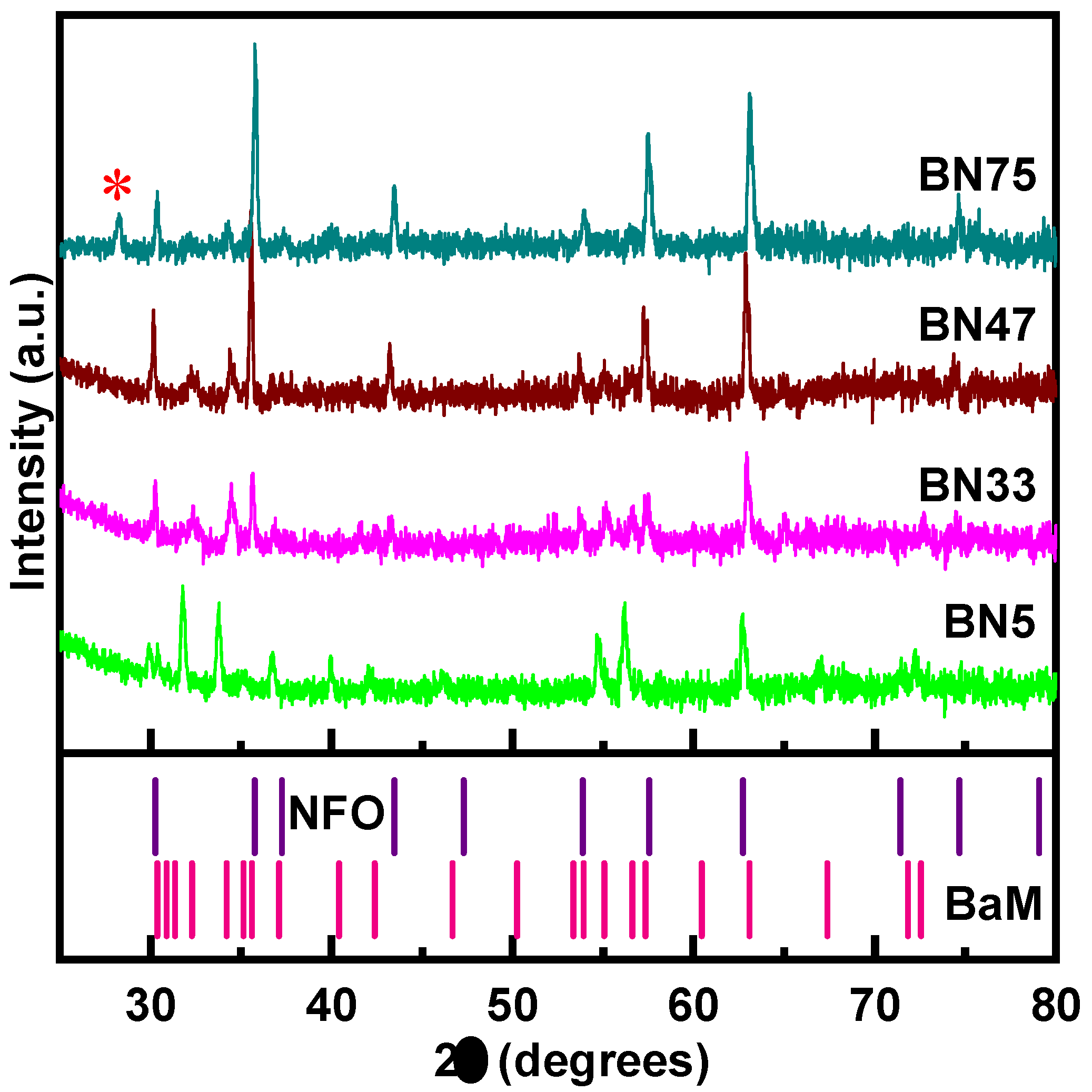
Figure 2.
SEM images for BN5, BN33, BN60 and BN95. There are no notable features in the image for BN5. Well defined hexagonal grains corresponding to the BaM phase is seen in BN33 and BN60. BN95 does not show any hexagonal grain.
Figure 2.
SEM images for BN5, BN33, BN60 and BN95. There are no notable features in the image for BN5. Well defined hexagonal grains corresponding to the BaM phase is seen in BN33 and BN60. BN95 does not show any hexagonal grain.
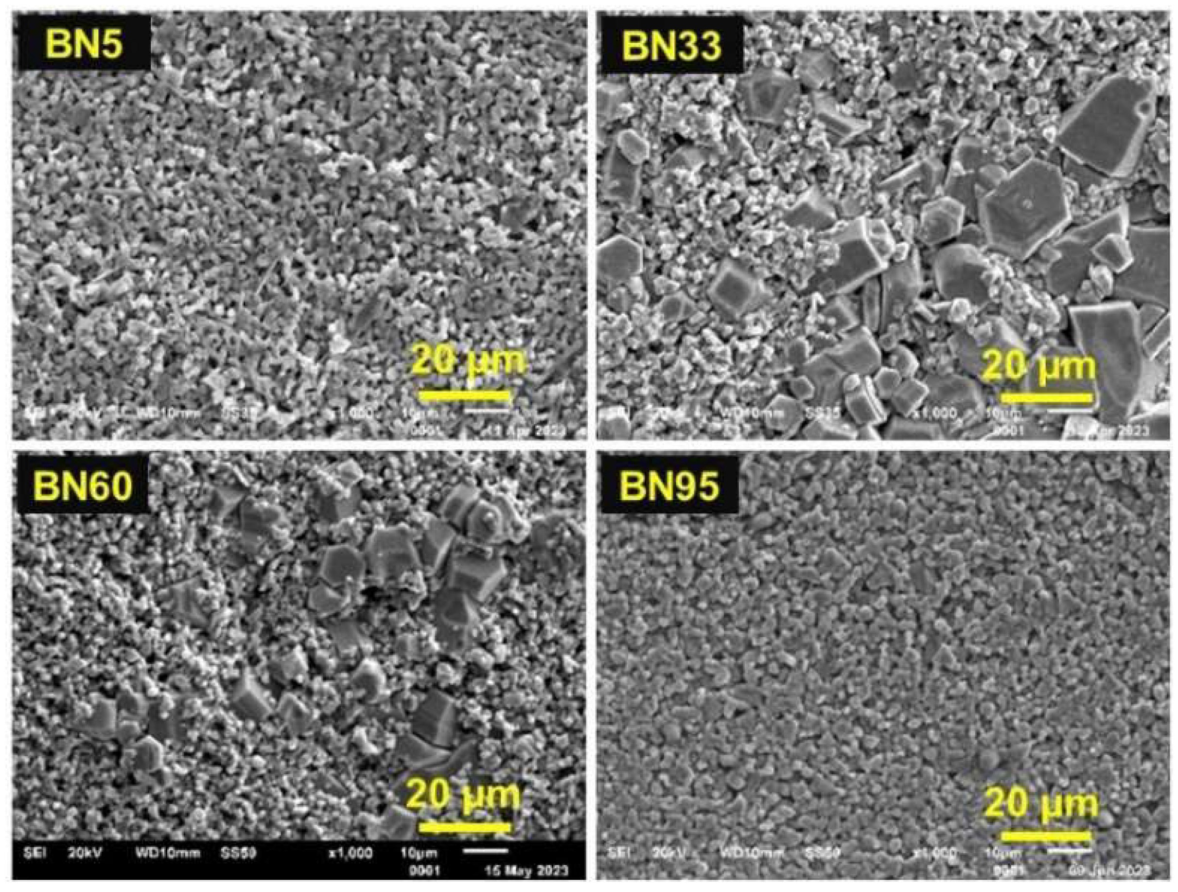
Figure 3.
Magnetostriction (λ11) data measured parallel to the in-plane H for BNx composites. The magnetic field was applied parallel to the length of the sample. λ11 for pure NFO is plotted in the inset.
Figure 3.
Magnetostriction (λ11) data measured parallel to the in-plane H for BNx composites. The magnetic field was applied parallel to the length of the sample. λ11 for pure NFO is plotted in the inset.
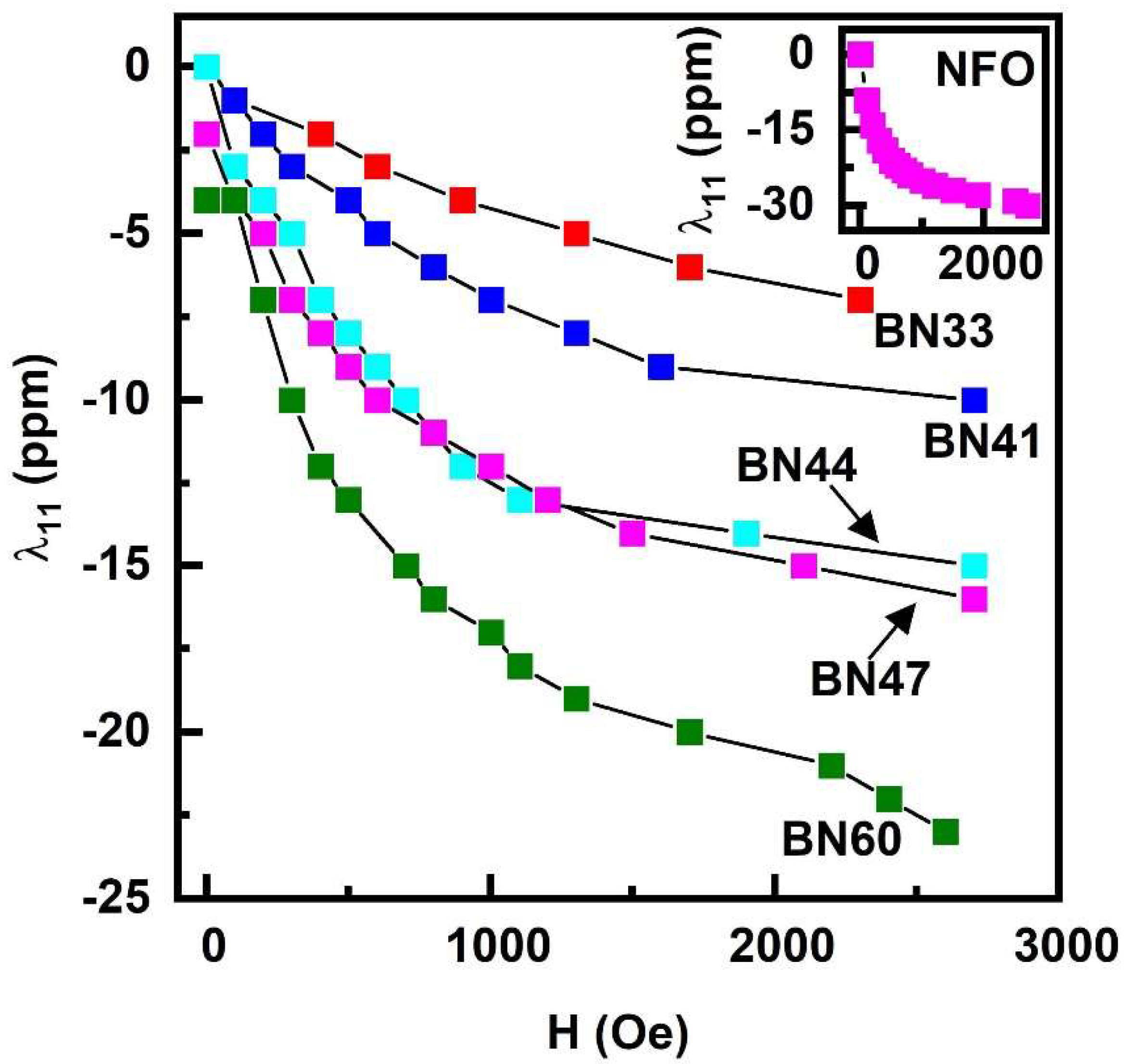
Figure 4.
Profiles of S21 vs f showing resonances in BN33, BN47, and BN60 composites for in-plane static magnetic fields. The absorption in the 5-20 GHz is due to ferromagnetic resonance in NFO. The resonance in the 40-50 GHz region is a magneto-dielectric mode in the composites.
Figure 4.
Profiles of S21 vs f showing resonances in BN33, BN47, and BN60 composites for in-plane static magnetic fields. The absorption in the 5-20 GHz is due to ferromagnetic resonance in NFO. The resonance in the 40-50 GHz region is a magneto-dielectric mode in the composites.
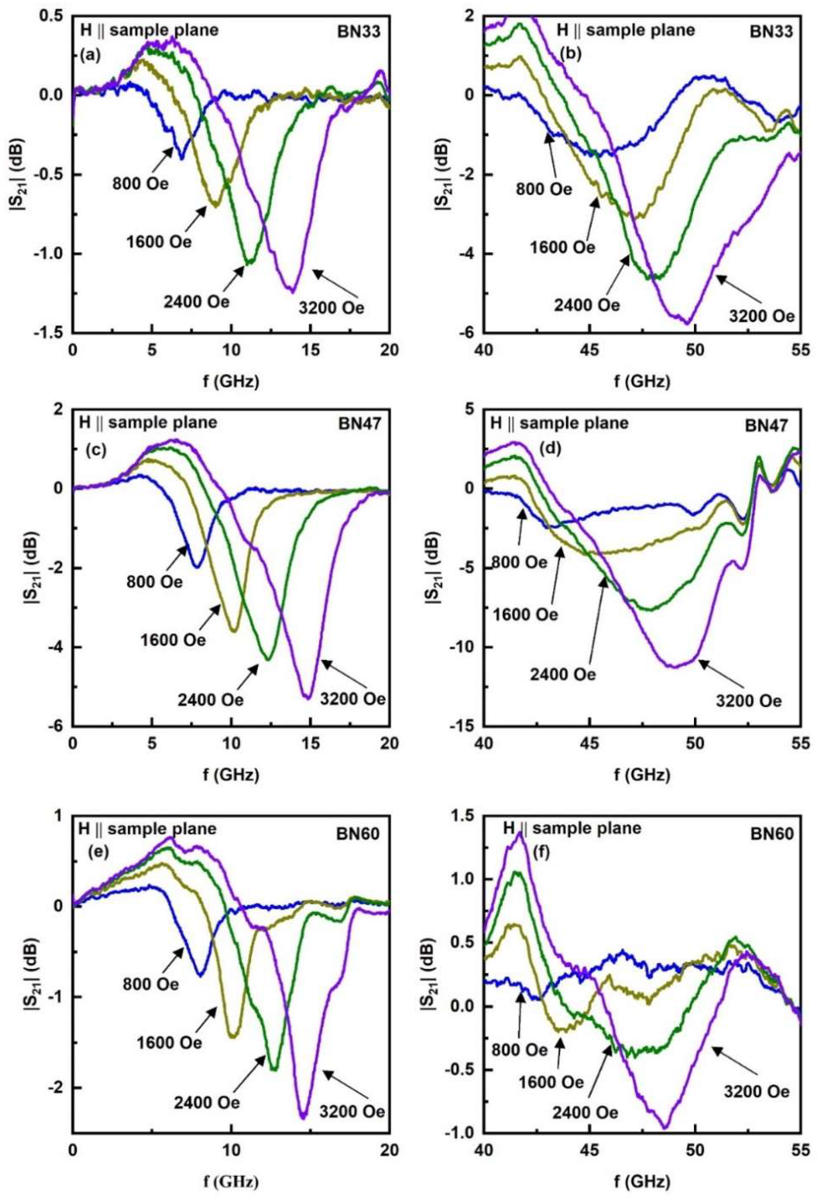
Figure 5.
Ferromagnetic resonance frequency fr as a function of H for (a) FMR observed in the low frequency region in Figure 4 and (b) magneto-dielectric mode frequency vs H for BNx composites.
Figure 5.
Ferromagnetic resonance frequency fr as a function of H for (a) FMR observed in the low frequency region in Figure 4 and (b) magneto-dielectric mode frequency vs H for BNx composites.
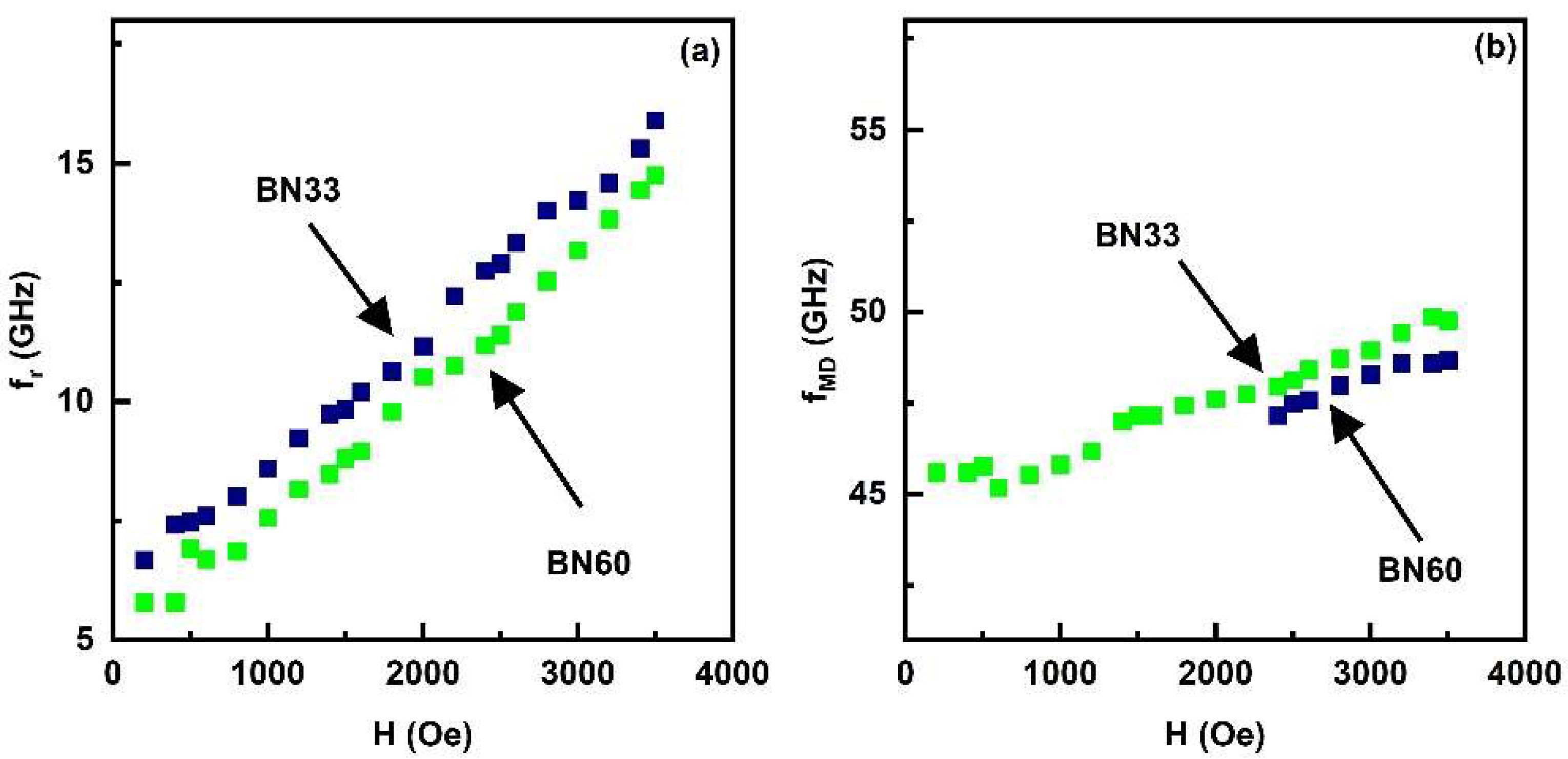
Figure 6.
Fitting of the FMR data on fr vs H to Eq. (1).
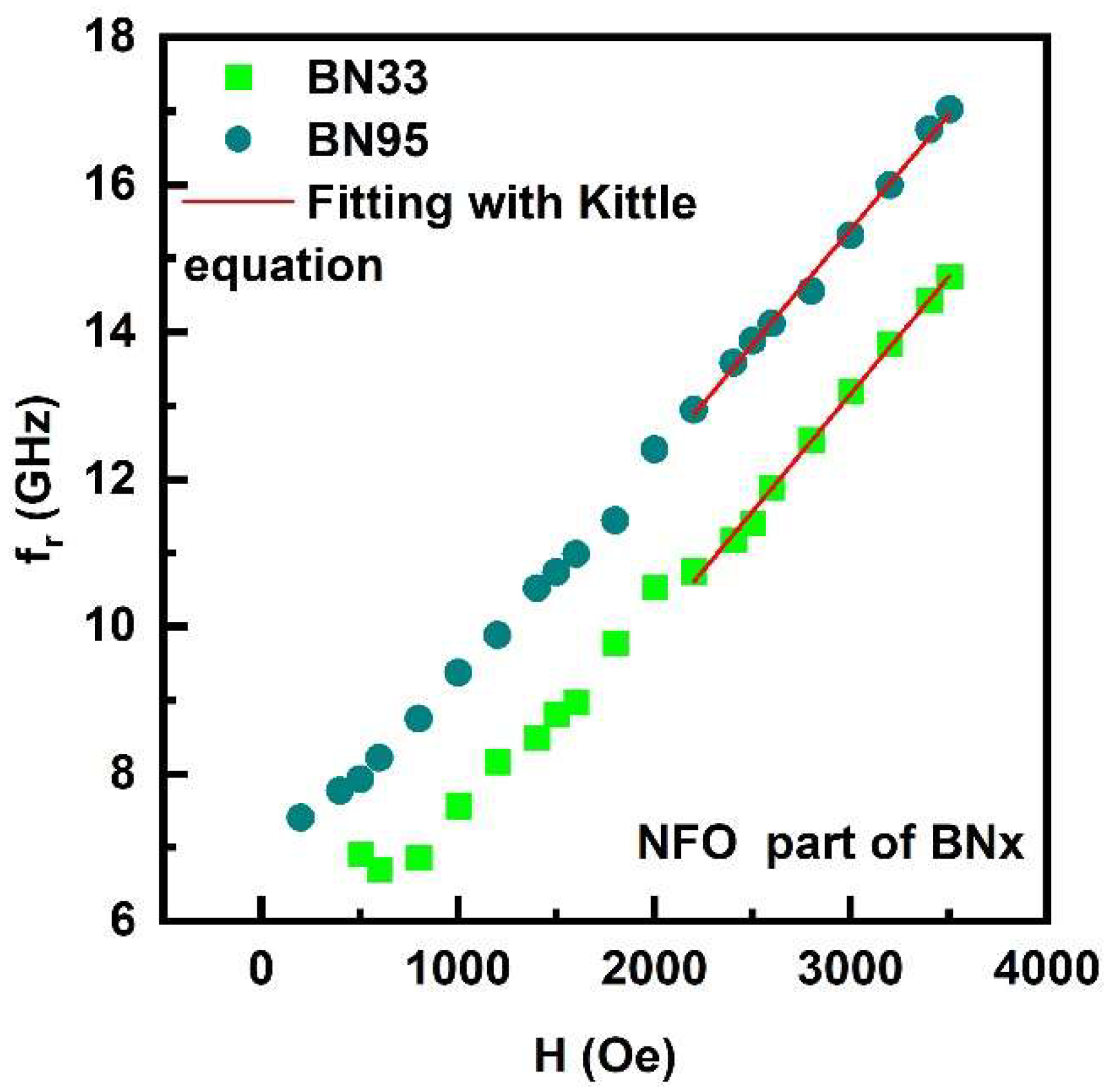
Figure 7.
Variation of the ME voltage coefficient MEVC α31 with the magnetic field H for both ac field h and DC magnetic field H applied parallel to the ferrite-PZT bilayer for (a) BN5-PZT, (b) BN33-PZT, (c) BN75-PZT and (d) BN95-PZT.
Figure 7.
Variation of the ME voltage coefficient MEVC α31 with the magnetic field H for both ac field h and DC magnetic field H applied parallel to the ferrite-PZT bilayer for (a) BN5-PZT, (b) BN33-PZT, (c) BN75-PZT and (d) BN95-PZT.
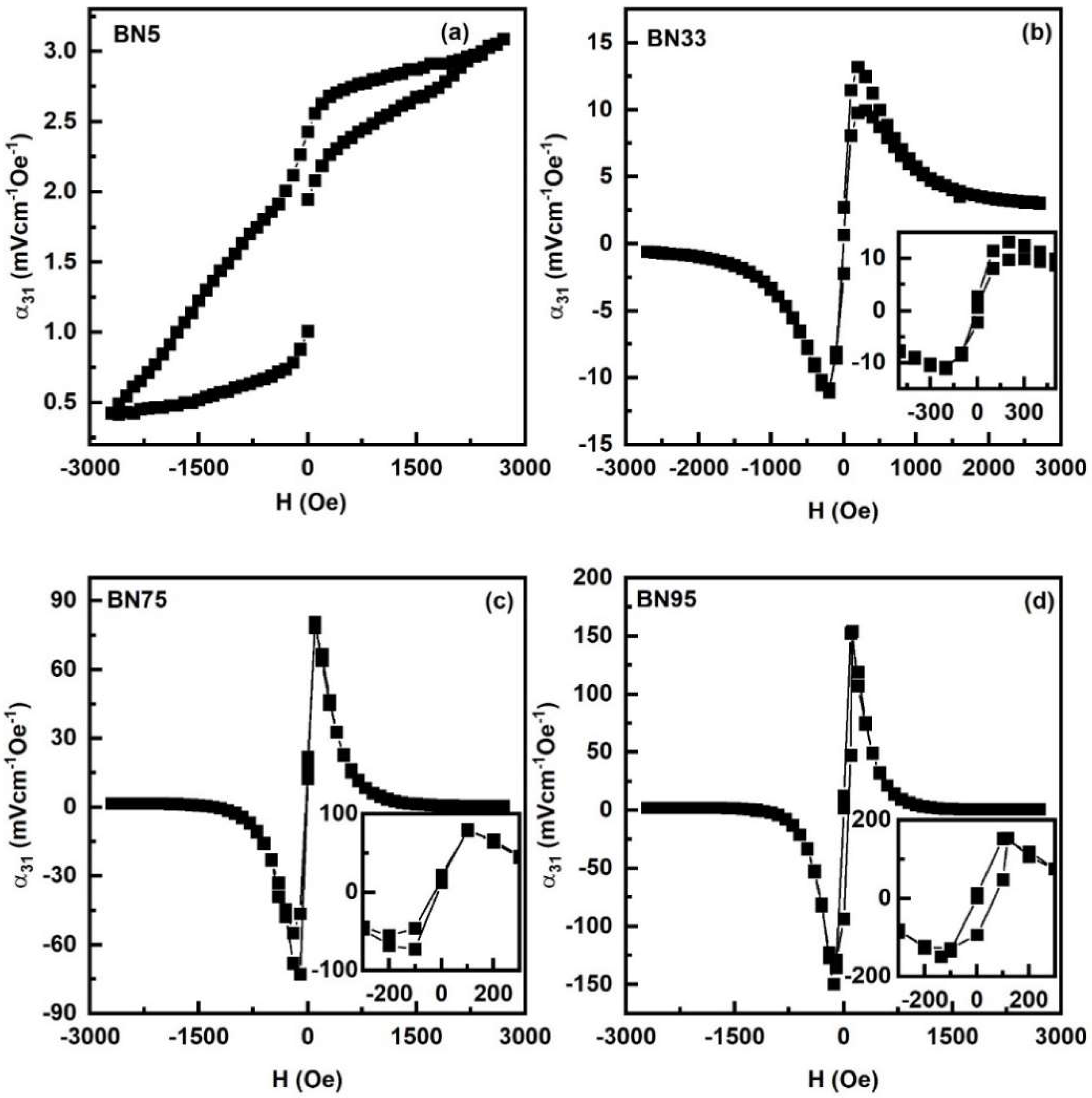
Figure 8.
Similar MEVC α33 vs H data as in Figure 7 for H and h applied perpendicular to the sample plane for bilayers of (a) BN5-PZT, (b) BN33-PZT, (c) BN75-PZT and (d) BN95-PZT.
Figure 8.
Similar MEVC α33 vs H data as in Figure 7 for H and h applied perpendicular to the sample plane for bilayers of (a) BN5-PZT, (b) BN33-PZT, (c) BN75-PZT and (d) BN95-PZT.
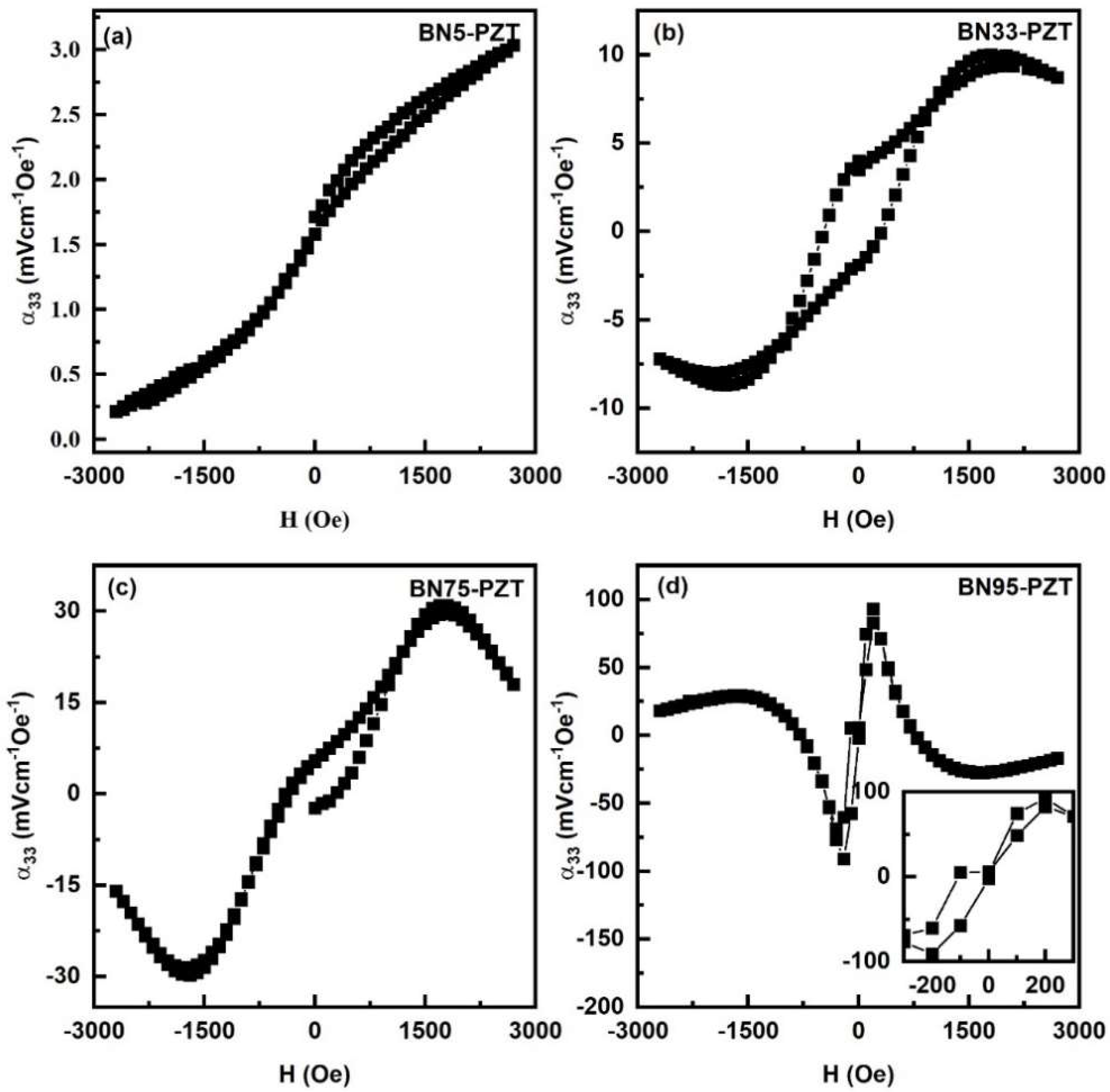
Figure 9.
Frequency dependence of ME coefficient α31 for bilayer of BNx-PZT. The peak values of MEVC occur at longitudinal mechanical resonance frequency in the samples.
Figure 9.
Frequency dependence of ME coefficient α31 for bilayer of BNx-PZT. The peak values of MEVC occur at longitudinal mechanical resonance frequency in the samples.
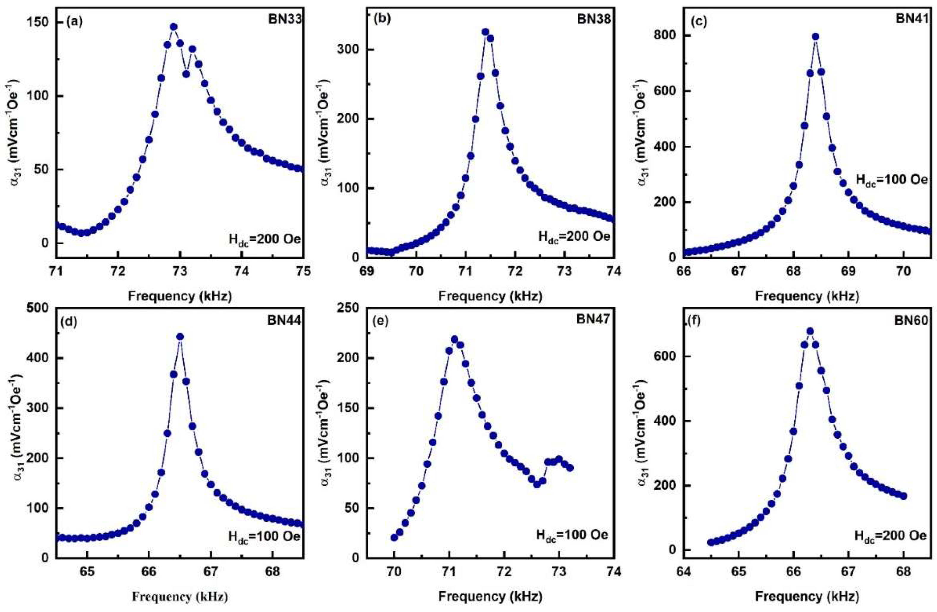

Table 1.
Gyromagnetic ration γ, effective saturation magnetization 4πMeff, and magnetic anisotropy field HA for the BaM-NFO composites estimated from ferromagnetic resonance.
Table 1.
Gyromagnetic ration γ, effective saturation magnetization 4πMeff, and magnetic anisotropy field HA for the BaM-NFO composites estimated from ferromagnetic resonance.
| Sample | Fitting parameters | Measured saturation magnetization, 4πMs (kG) | HA (kOe) | |
| γ (GHz/kOe) | 4πMeff (kG) | |||
| BN33 | 3.17 | 3.53 | 4.15 | -0.62 |
| BN38 | 3.26 | 3.46 | 4.41 | -0.95 |
| BN41 | 3.03 | 4.80 | 3.76 | 1.04 |
| BN44 | 2.96 | 5.30 | 3.38 | 1.92 |
| BN47 | 2.98 | 5.51 | 3.54 | 1.97 |
| BN60 | 2.61 | 10.07 | 3.37 | 6.70 |
| BN75 | 2.25 | 15.74 | 3.35 | 12.39 |
| BN85 | 2.98 | 7.49 | 3.96 | 3.53 |
| BN95 | 2.96 | 7.25 | 3.78 | 3.47 |
Disclaimer/Publisher’s Note: The statements, opinions and data contained in all publications are solely those of the individual author(s) and contributor(s) and not of MDPI and/or the editor(s). MDPI and/or the editor(s) disclaim responsibility for any injury to people or property resulting from any ideas, methods, instructions or products referred to in the content. |
© 2023 by the authors. Licensee MDPI, Basel, Switzerland. This article is an open access article distributed under the terms and conditions of the Creative Commons Attribution (CC BY) license (http://creativecommons.org/licenses/by/4.0/).
Copyright: This open access article is published under a Creative Commons CC BY 4.0 license, which permit the free download, distribution, and reuse, provided that the author and preprint are cited in any reuse.


