
Submitted:
16 October 2023
Posted:
17 October 2023
You are already at the latest version
Abstract
The majority of current methods for measuring the angular deflection of a laser beam enable measurement only in one selected plane. However, there are tasks in which measurements of laser beam deflections in 3D are required. In this paper, we present a way of enabling two-axial measurements of the deflection of a beam based on a single-axis sensor. The key idea is to direct a laser beam alternately into one of two arms of a measurement system. In the first arm, the beam is transmitted directly to the angular sensor, while in the second, the beam is directed to the sensor via a special optical element that rotates the plane of the beam deflection; in other words, this element changes the deflection in the horizontal plane into a deflection in the vertical plane, and vice versa. To alternate the path of the beam, a variable phase retarder and a polarising beamsplitter are used. The proposed technique is experimentally verified, and the results confirm its effectiveness.
Keywords:
angular microdeflections
; interferometric sensor
; two-axial measurement
; optical beam deflection sensing (OBDS)
; variable phase retarder
1. Introduction
There are various methods of measuring the angular deflection of a laser beam, including approaches based on position (triangulation) [1,2,3], autocollimation [4], the critical angle effect [5,6,7,8,9,10,11,12] and interference [13,14,15,16,17,18,19]. Some of these methods, such as the interference-based methods described in [17,18,19], enable only single-axis measurement, where the sensors are sensitive only to laser beam deflections in one selected plane. This type of deflection can be also presented as a rotation of the laser beam around a selected axis.
To describe how single-axis sensors respond to angular deflections of the laser beam in any other direction, the angular deflection of the beam needs to be expressed as a combination of two orthogonal components, i.e., angular deflections in two perpendicular planes, for example vertical and horizontal. A single-axis sensor measures only one of these components: the deflection in the sensitivity plane of the sensor. The second component is not measured, and in some cases this decreases the accuracy of the sensor.
To solve this problem, a pair of single-axis beam deflection sensors can be used. In the most basic setup, the second sensor is rotated by 90° relative to the first sensor, so they are taking measurements in two perpendicular planes. This solution was applied in [20] to simultaneously measure the two rotational errors of a coordinate measuring machine. The idea presented in the present study involves the application of an optical element which rotates the plane of the beam deflection. When the beam passes through this element, its deflection in the horizontal plane is changed to a deflection in the vertical plane, whereas its deflection in the vertical plane is changed to a deflection in the horizontal plane. In this approach, both sensors may have the same orientation. An example of the application of this idea is described in [21].
In the present paper, an optical setup for two-axial measurements of the angular deflections of a laser beam is presented. Only one single-axis beam deflection sensor is used, and the beam is alternatively directed to the two arms of the optical setup. The first arm of the optical setup contains only a non-polarising beamsplitter and a polariser; the direction of the beam deflection in this arm remains the same as on entry to the setup. The second arm of the setup includes an optical element that rotates the beam deflection. The beams from both arms are passed to the same single-axis sensor. By alternating the path of the beam, alternating measurements of the beam deflections can be made in two perpendicular planes. In the proposed setup, a variable phase retarder is used to alternate the path of the beam.
In this paper, we also present some results of beam deflection measurements. These results provide proof that two-axial measurements are possible using only one single-axis sensor. In future, if the proposed solution is widely adopted, it could reduce the number of sensors needed in laboratories or industry, thus creating the possibility of reducing equipment costs.
2. Materials and Methods
2.1. Optical Element for the Rotation of Laser Beam Deflections
The solution proposed in this paper is based on a special optical prism which rotates laser beam deflections, and this needs to be described before the solution itself is presented. This optical element consists of two right-angled prisms that are rotated by 90° in relation to each other and cemented together by an adjoining wall, as shown in Figure 1.
The dashed red line shows the nominal path of the beam, i.e., the path of the beam when it has not been deflected in any direction. If the global coordinate system XYZ is oriented as shown in the figure, the beam enters the optical element in the X-direction and leaves it in the −Y-direction. To describe the deflections of the beam, we introduce the local coordinate systems XiYiZi and XoYoZo, where the indices i and o represent the local coordinate systems of the input and output beams, respectively. Axes Xi and Xo are positioned along direction of the nominal path of the beam: if the nominal path of the beam is horizontal, then axes Zi and Zo are vertical and point upwards (parallel to the Z-axis of the global coordinate system).
The first case is illustrated in Figure 1 by the solid blue line. The deflection angle φ represents an angle of rotation around the Zi-axis. The deflection angle φ shown in the figure is counterclockwise, looking from above the XiYi plane, and we assume that it has a positive value. After passing through the optical element and undergoing two reflections inside it, the output beam is deflected in the vertical plane. In the local coordinate systems, a rotation around the Zi-axis changes to a rotation around the Yo-axis of the same value but with the opposite sign (clockwise looking from above the XoZo plane). The angle of rotation of the output beam around the Yo axis has a value of −φ (the absolute value is the same, but the sign is negative). Hence, in the global coordinate system, a rotation around the Z-axis is changed to a rotation around the X-axis with the same absolute value but with the opposite sign.
The second case is illustrated in Figure 1 by the solid red line. The deflection angle ϑ is an angle of rotation around the Yi-axis. In this case, the deflection angle of the beam before entering the optical element has a negative value (clockwise looking from above the XiZi plane). The direction of the beam deflection was chosen for better visibility of the beam path, as the output beam is deflected in the horizontal plane. In the local coordinate systems, a rotation around the Yi-axis changes to a rotation around the Zo-axis with the same value and the same sign. An angle of rotation of the output beam around the Zo axis has a negative value of ϑ. Hence, in the global coordinate system, a rotation around the Y-axis changes to a rotation around the Z-axis with the same absolute value and with the same sign.
In the above analysis, we have assumed that input beam is inclined at exactly 45° with respect to the reflecting surface.
In view of the usage of the proposed optical element, it is important that the absolute value of the rotation of the output laser beam around the Yo-axis (|φL|) is equal to the absolute value of the rotation of the input laser beam around the Zi-axis (|φE|). The accuracy of this conversion was determined in [22], and the error in the conversion ΔEC (the difference between the −φL and φE values) can be approximated by Equation 1:
where RY is the rotation of the optical element around the Y-axis relative to its nominal position in degrees, and ϑE is the rotation of the entering laser beam around the Aϴ1 axis.
ΔEC ≈ 0.018 * RY * ϑE,
There are other factors influencing the accuracy of this measurement, for example the rotation of the optical element around the Z-axis RZ; however, these are less important, as their influence is smaller.
Since any significant rotation of the optical element around the Y-axis can be a major source of error in the measurement of laser beam deflection, it was decided that in the experimental setup, the optical element should have an angular adjustment in the XZ plane.
2.2. Method of Two-Axial Measurement with One Single-Axis Sensor
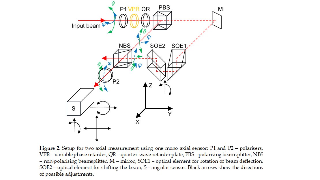
A schematic diagram of the proposed method of two-axial measurement with one single-axis sensor is shown in Figure 2.
The laser beam for which the deflections are measured is depicted as a solid red line. Its deflection in the vertical plane is designated as ϑ, while its deflection in the horizontal plane is designated as φ. Depending on the controlling signal sent to the variable phase retarder VPR, the beam that passes through polariser P1, the variable phase retarder VPR and the quarter-wave plate QR has a vertical or a horizontal polarisation (a more detailed description of the subsystem for altering the beam polarisation will be given in Section 2.3). If the polarisation is vertical, the beam is fully reflected by the polarising beamsplitter PBS. The path of the reflected beam is shown by the short-dashed red line. In this case, the beam enters the non-polarising beamsplitter NBS, and the transmitted part of the beam passes through the polariser P2, where it finally enters the angular sensor S. The sensor measures the vertical component (ϑ) of the initial beam deflection. Polariser P2 is necessary because the use of sensor S requires that the beam is polarised at an angle of 45°. A more detailed description of the sensor is given in Section 2.4.
If the polarisation of the beam entering the polarising beamsplitter PBS is horizontal, the beam is fully transmitted. Its path in Figure 2 is shown by the long-dashed red line. It is reflected by the mirror M and enters optical element SOE1, which rotates the deflection of the beam through 90°. After passing through this element, the vertical component of the beam deflection ϑ is replaced by the horizontal component of the initial beam deflection φ. After this rotation, the beam is raised by optical element SOE2 and enters the non-polarising beamsplitter BS. The reflected part of the beam passes through polariser P2 and enters sensor S. Since the vertical deflection of the beam is now equal to the horizontal deflection of the initial beam (φ), the sensor measuring only in the vertical plane now measures the horizontal deflection of the initial beam.
Although the optical element SOE1 changes the sign of the horizontal component of the initial beam deflection, the mirror M also changes this sign, meaning that the overall sign is not changed.
2.3. Subsystem for Altering the Beam Polarisation
The principle of operation for the subsystem altering the beam polarisation is shown in Figure 3.
The beam passes through polariser P1, which ensures that the beam entering the variable phase retarder VPR has a linear polarisation at an angle of 45° (shown by the green arrows in Figure 3). The variable phase retarder is applied to change the polarisation of the beam to right-hand circular (shown in the figure as a blue circle with arrows) or left-hand circular (shown in the figure as a red circle with arrows). The direction of circular polarisation depends on the amplitude of the signal controlling the variable phase retarder. The circularly polarised beam then passes through the quarter-wave plate retarder QR, which is fixed at an angle of 45°. This plate changes the right-hand circular polarisation to vertical polarisation (shown by blue arrows in the figure), and changes the left-hand circular polarisation into horizontal polarisation (shown by red arrows in the figure).
For the experimental setup described below in Section 2.5, exact values of the amplitude of the signal controlling the variable phase retarder were set in such a way to obtain maximum of light intensity alternately in the first or in the second arm of the set-up (shown in Figure 2).
2.4. Single-Axis Sensor for Laser Beam Deflection
The method proposed in this paper can be applied with (almost) any mono-axial sensor for the angular deflection (or microdeflection) of a laser beam. However, it was developed for use with the sensor described in [17,18,20,21], and the results presented here were obtained using a sensor of this type. This was an interference-based sensor, and its main principle of operation is shown in Figure 4.
The main subsystem of the applied sensor is an optical system consisting of a polarising beamsplitter PB, corner cube reflector CCR and right-angle prism P90. The beam entering this optical system must have a linear polarisation at an angle of 45°. Half of the beam passes through the polarising beamsplitter, while the other half is reflected to the corner cube reflector. After undergoing reflection in the prism and the corner cube reflector, both halves of the beam are returned to the beamsplitter. The half of the beam from the prism passes through the beamsplitter, while the half of the beam from the corner cube reflector is reflected. As a result, if the initial beam is propagating in the horizontal direction, both parts of the input beam leave the optical system in the same direction. This case is shown in Figure 4 by the dashed red line. However, if the input beam is deflected in the vertical direction (for example, downwards) by an angle ε, the half of the beam reflected by the prism (shown as a continuous red line) leaves the optical system still propagating downwards, while the half of the beam reflected by the corner cube reflector (shown as a continuous blue line) leaves the system parallel to the initial beam, i.e., upwards. In this case, the angle between the two beams leaving the optical system is 2ε. A similar situation arises if the initial beam is deflected upwards. It is important to note that the projections of the beams leaving the optical system onto the horizontal plane are always parallel (overlap).
If two coherent beams with plane wavefronts, the same polarisation and a deflection by a small angle 2ε overlap, they interfere, and the interference pattern consists of fringes with a constant (period) δ given by Equation 2 [17]:
where λ is the wavelength of the beams. For the case of the sensor described above, the beams leaving the optical system in Figure 4 have perpendicular polarisations. To enable interference between them, an additional polariser set to 45° is used (which is not shown in the figure). Behind this polariser, a photodetector system is placed. This system enables the fringe constant δ to be determined, which then allows for the angle ε to be calculated.
δ = λ / [2sin(ε)] ≈ λ / 2ε,
Various photodetector systems can be used; for example, in [19] the application of a CCD camera is described. In the sensor used to verify the proposed method of two-axial measurements, the same photodetector system (eight photodiodes in a row) was applied with the main settings reported in [20]. Each photodiode is 200 µm wide. If the value of the signal from the first photodiode is labelled as I1, the value of the signal from the second photodiode as I2, and so on, then the function F related to the fringe constant is given by Equation 3 [17]:
F = (I7 - I5 - I4 + I2) / [1.85(I4 + I5) - I3 - I6].
The values of this function are normalised to the range [−1, 1]. The value of the angle α can then be calculated according to Equation 4 (the function F after normalisation is labelled as Fn) [17]:
α = 25.1287 Fn^7 + 0.648825 Fn^6 − 18.1042 Fn^5 − 0.951463 Fn^4
+ 16.6809 Fn^3 + 0.206846 Fn^2 + 63.9919 Fn.
+ 16.6809 Fn^3 + 0.206846 Fn^2 + 63.9919 Fn.
The value of the angle α changes by the same amount as the angle ε, but also contains an initial angle ε0 that is related to the centre of the measurement range. In this configuration, the sensor does not enable absolute measurements, and these require the configuration with the CCD camera.
Figure 2 shows the four adjustment axes of the sensor position and orientation. Linear adjustments should be made so that the spot of the laser beam is located at the centre of the photodetector system. The adjustment around the Z-axis should be done so that the optical path lengths for the beams reflected by the prism and the corner cube reflector are equal. The adjustment around the Y-axis should be made so that the measured angle values are within the measurement range. The precision of these adjustments influences the accuracy of the sensor.
2.5. Setup Used for Experimental Verification of the Proposed Method
To verify the effectiveness of the proposed method, the setup presented in Figure 5 was assembled. The labels are consistent with those of Figure 2, and the setup included polarisers P1 and P2, variable phase retarder VPR, quarter-wave plate QR, polarising beamsplitter PBS, non-polarising beamsplitter PS, fixed mirror M, optical elements SOE1 and SOE2, and the sensor. This part of the larger setup was assembled as shown in Figure 2. For the variable phase retarder, an ARCoptix Variable Phase Retarder was used.
The source of the light was an He-Ne laser containing a beam expander and collimator. The collimator was required because the interfering beams in the sensor need to have approximately plane wavefronts. To deflect the laser beam through the set angles (ϑ in the vertical plane and φ in the horizontal plane), a mirror on a two-axial, rotational piezotranslator was used. In the horizontal plane, a factor equal to square root of two was applied, as the controlling mirror was rotated through an angle of 45°.
Due to the characteristics of the piezotranslator, the amplification in both the vertical and horizontal planes varied [22], while the voltage values (before applying the factor of the square root of two) were set the same for both axes. For this reason, the set values of ϑ and φ were different: ϑ nominally ranged from zero to 17.95 µrad, while φ nominally ranged from zero to 15.11 µrad. These small ranges for the set values in the experiments were selected since measurements of similar angles were performed in [20].
A total of five experiments were performed. In Experiment 1, only the value of ϑ was measured. The variable phase retarder was set so that the beam was reflected by the polarising beamsplitter directly to the sensor, and there was no change in the amplitude of the signal controlling the variable phase retarder. This experiment was carried out to test the performance of the sensor itself. Although earlier tests of this type of sensor had been done, this experiment was necessary because the accuracy of the sensor depends on the precision of its adjustment.
In Experiments 2 and 3, both angles were measured. They were changed simultaneously from zero to 17.95 µrad for ϑ and from zero to 15.11 µrad for φ, which was done incrementally with constant steps (where the step was constant for a given direction, but different for each direction). After each step, a measurement was made in both directions. There were 19 steps and 20 measurements for each angle (as the first measurements were made for angles of zero).
In Experiment 4, both angles were measured, but only ϑ was changed, whereas in Experiment 5 both angles were measured while only φ was changed.
3. Results
The results of Experiment 1 are shown in Figure 6.
In this experiment, the maximum absolute error in the measurement of ϑ was 1.24 µrad. It may be more significant that the R2 value for a linear fit (calculated using Statgraphics software) was 99.9274%. The linear characteristic of a measurement system is important, because even if there were some systematic error, for example caused by an error in the determination of the piezotranslator amplification, the proportional response of the measurement system verifies the performance of the method.
The results of Experiment 2 are presented in Figure 7, while those for Experiment 3 are shown in Figure 8. Since Experiments 2 and 3 were similar, these results will be described together.
In Experiment 2, the maximum absolute error in the measurement of ϑ was 0.59 µrad, while the absolute error in the ϑ measurement was 1.81 µrad. The R2 values for the linear fits were 99.9277% for ϑ and 99.7965% for φ. In Experiment 3, the maximum absolute error in the measurement of ϑ was 1.45 µrad, while that for ϑ was 1.39 µrad. The R2 values for the linear fits were 99.9316% for ϑ and 99.7383% for φ. None of the errors in Experiments 2 and 3 exceeded 2 µrad.
Experiment 4 was performed to test whether the value of φ influenced the measurement of ϑ. The results of this experiment are presented in Figure 9, while a comparison of the ϑ values obtained from Experiments 2, 3, and 4 is shown in Figure 10.
In Experiment 4, the maximum absolute error in the measurement of ϑ was 0.62 µrad, while the R2 value for a linear fit was 99.8529%. The maximum absolute error in the measurement of φ was 0.84 µrad. The maximum difference between the corresponding values of ϑ obtained from Experiments 2, 3, and 4 was 1.62 µrad, a value similar to those obtained in the single experiments.
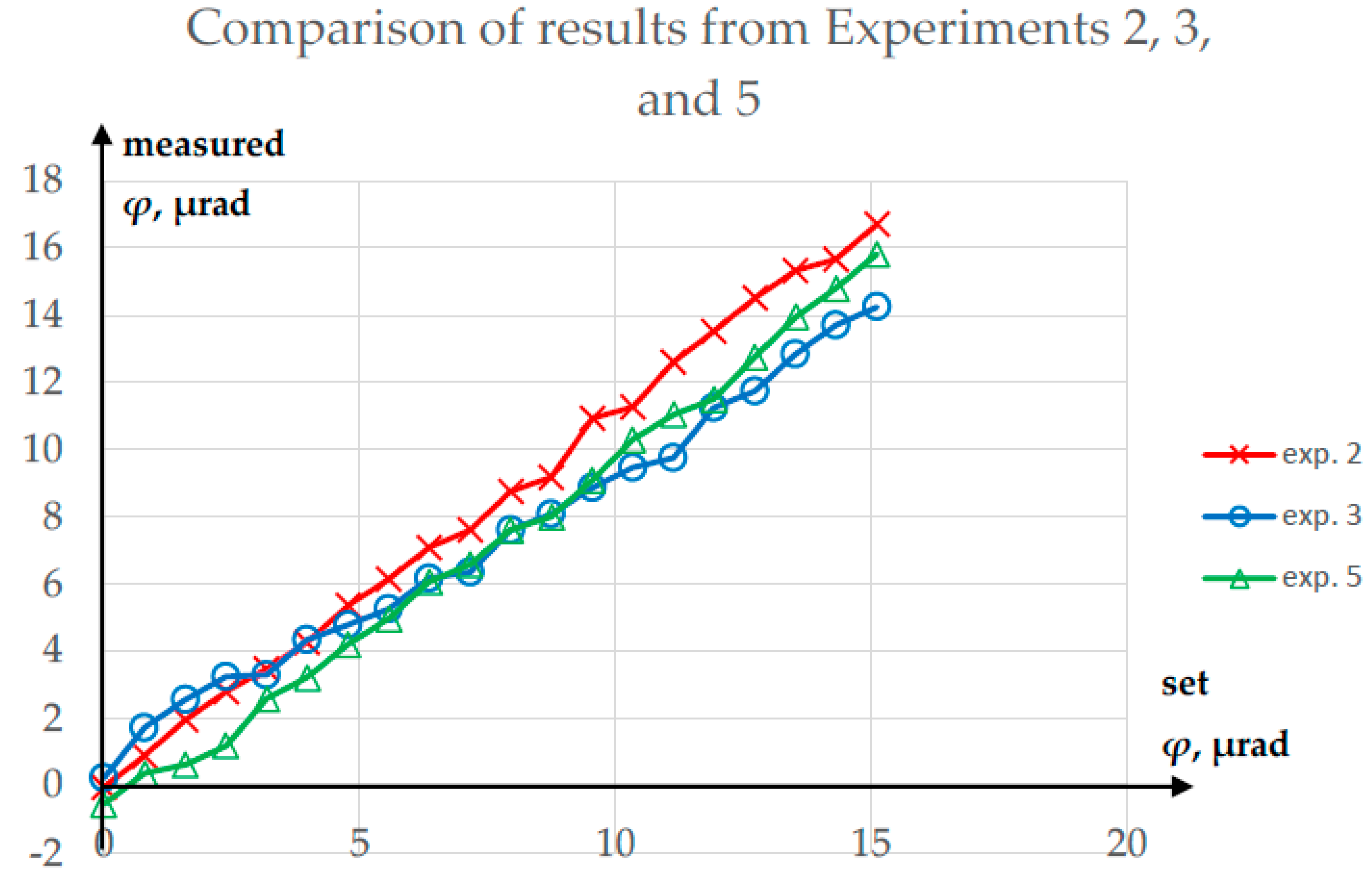
Experiment 5 was performed to test whether the value of ϑ influenced the measurement of φ. The results of this experiment are presented in Figure 11, while a comparison of the φ values obtained from Experiments 2, 3, and 5 is shown in Figure 12.
In Experiment 5, the maximum absolute error in the measurement of φ was 1.22 µrad, while the R2 value for a linear fit was 99.6856%. The maximum absolute error in the measurement of ϑ was 3.15 µrad. However, one measurement of ϑ was clearly an outlier; after elimination of this data point, the maximum absolute error in ϑ decreased to 1.27 µrad.
The maximum difference between corresponding φ values obtained from Experiments 2, 3, and 5 was 2.85 µrad. However, the graph in Figure 12 shows that the source of this relatively large maximum difference lay not in the influence of ϑ, but in the repeatability of the measurement itself. When the corresponding φ values obtained from Experiments 2 and 3 were averaged, the maximum difference relative to the results from Experiment 5 decreased to 1.84 µrad.
Since after elimination of the outlier, the error in the measurement did not exceed ±2 µrad in either direction (vertical or horizontal), these results prove that the proposed method is effective.
4. Discussion
The proposed method of two-axial measurement of a laser beam angular (micro) deflection was successfully verified experimentally. The use of only one single-axis sensor rather than two such sensors could decrease the cost of measurement equipment and make the required adjustments easier and quicker.
The range of set values in the experiments was selected to allow the proposed method to be used for testing the rotational errors of coordinate measuring machines [20]. The obtained measurement errors provide evidence that this type of application is possible. The accuracy of a two-axial system with only a single sensor appears to be no worse than the accuracy of the two-sensor system presented in [20].
The proposed method can be applied using other sensors of the angular deflection of a laser beam and in other fields of science or engineering. It is possible that in the case of higher measurement ranges, the influence of the deflection in the perpendicular direction on the measurement of deflection will become important; if so, the simple formula in Equation 1 can be used for a numerical correction.
In conclusion, it is possible to measure laser beam angular deflections in two perpendicular directions by applying only one mono-axial sensor. The solution involves alternately directing the laser beam to the sensor through two arms of the measurement system, where only one of them contains an optical element to rotate the deflection.
5. Patents
The method described in this paper is patented in Poland. The patent number is PL 241303 and the patent title is ‘Method for measuring angular deviations of a laser beam and the optical system for measuring angular micro-deviations of a laser beam’.
Author Contributions
Conceptualization, M. Dobosz and M. Jankowski; methodology, M. Dobosz; software, J. Mruk; validation, J. Mruk; formal analysis, M. Jankowski and J. Mruk.; investigation, J. Mruk; resources, M. Dobosz and M. Jankowski; data curation, J. Mruk and M. Jankowski; writing—original draft preparation, M. Jankowski; writing—review and editing, M. Dobosz; visualization, M. Jankowski; supervision, M. Dobosz; project administration, M. Dobosz; funding acquisition, M. Dobosz. All authors have read and agreed to the published version of the manuscript.
Funding
This work was sponsored by statutory funds.
Institutional Review Board Statement
Not applicable.
Informed Consent Statement
Not applicable.
Data Availability Statement
Publicly available datasets were analyzed in this study. This data can be found here.
Acknowledgments
The authors would like to thank Olga Iwasińska-Kowalska for help in the researches.
Conflicts of Interest
The authors declare no conflict of interest.
References
- Putman, C.A.J.; De Grooth, B.G.; Van Hulst, N.F.; Greve, J. A Detailed Analysis of the Optical Beam Deflection Technique for Use in Atomic Force Microscopy. J. Appl. Phys. 1992, 72, 6–12. [Google Scholar] [CrossRef]
- Meyer, G.; Amer, N.M. Optical-beam-deflection Atomic Force Microscopy: The NaCl (001) Surface. Appl. Phys. Lett. 1990, 56, 2100–2101. [Google Scholar] [CrossRef]
- Levesque, M.; Mailloux, A.; Morin, M.; Galarneau, P.; Champagne, Y.; Plomteux, O.; Tiedtke, M. Laser Pointing Stability Measurements. In Proceedings of the Third International Workshop on Laser Beam and Optics Characterization; Morin, M., Giesen, A., Eds.; SPIE, 1996; Vol. 2870; pp. 216–224. [Google Scholar]
- ISO 11670:2003 — Lasers and Laser-Related Equipment — Test Methods for Laser Beam Parameters — Beam Positional Stability 2003.
- Huang, P.S.; Kiyono, S.; Kamada, O. Angle Measurement Based on the Internal-Reflection Effect: A New Method. Appl. Opt. 1992, 31, 6047–6055. [Google Scholar] [CrossRef] [PubMed]
- Huang, P.S.; Ni, J. Angle Measurement Based on the Internal-Reflection Effect Using Elongated Critical-Angle Prisms. Appl. Opt. 1996, 35, 2239–2241. [Google Scholar] [CrossRef] [PubMed]
- Zhang, S.; Kiyono, S.; Uda, Y. Nanoradian Angle Sensor and in Situ Self-Calibration. Appl. Opt. 1998, 37, 4154–4159. [Google Scholar] [CrossRef] [PubMed]
- Villatoro, J.; García-Valenzuela, A. Measuring Optical Power Transmission near the Critical Angle for Sensing Beam Deflection. Appl. Opt. 1998, 37, 6648–6653. [Google Scholar] [CrossRef] [PubMed]
- Gray, J.; Thomas, P.; Zhu, X.D. Laser Pointing Stability Measured by an Oblique-Incidence Optical Transmittance Difference Technique. Rev. Sci. Instrum. 2001, 72, 3714–3717. [Google Scholar] [CrossRef]
- García-Valenzuela, A.; Diaz-Uribe, R. Detection Limits of an Internal-Reflection Sensor for the Optical Beam Deflection Method. Appl. Opt. 1997, 36, 4456–4462. [Google Scholar] [CrossRef] [PubMed]
- Zhang, A.; Huang, P.S. Total Internal Reflection for Precision Small-Angle Measurement. Appl. Opt. 2001, 40, 1617–1622. [Google Scholar] [CrossRef] [PubMed]
- García-Valenzuela, A.; Sandoval-Romero, G.E.; Sánchez-Pérez, C. High-Resolution Optical Angle Sensors: Approaching the Diffraction Limit to the Sensitivity. Appl. Opt. 2004, 43, 4311–4321. [Google Scholar] [CrossRef]
- Garcia-Valenzuela, A.; Pena-Gomar, M.; Villatoro, J. Sensitivity Analysis of Angle-Sensitive Detectors Based on a Film Resonator. Opt. Eng. 2003, 42, 1084–1092. [Google Scholar] [CrossRef]
- Garcia-Valenzuela, A.; Diaz-Uribe, R. Approach to Improve the Angle Sensitivity and Resolution of the Optical Beam Deflection Method Using a Passive Interferometer and a Ronchi Grating. Opt. Eng. 1997, 36, 1770–1778. [Google Scholar] [CrossRef]
- Kwee, P.; Seifert, F.; Willke, B.; Danzmann, K. Laser Beam Quality and Pointing Measurement with an Optical Resonator. Rev. Sci. Instrum. 2007, 78, 73103. [Google Scholar] [CrossRef] [PubMed]
- Morrison, E.; Meers, B.J.; Robertson, D.I.; Ward, H. Automatic Alignment of Optical Interferometers. Appl. Opt. 1994, 33, 5041–5049. [Google Scholar] [CrossRef] [PubMed]
- Dobosz, M. Interference Sensor for Ultra-Precision Measurement of Laser Beam Angular Deflection. Rev. Sci. Instrum. 2018, 89, 115003. [Google Scholar] [CrossRef] [PubMed]
- Dobosz, M.; Iwasinska-Kowalska, O. Interference Method for Ultra-Precision Measurement and Compensation of Laser Beam Angular Deflection. Appl. Opt. 2014, 53, 111–122. [Google Scholar] [CrossRef] [PubMed]
- Dobosz, M.; Jankowski, M. Interferometric, Absolute Sensor of Angular Micro-Displacement. Precis. Eng. 2021, 72, 250–258. [Google Scholar] [CrossRef]
- Dobosz, M.; Jankowski, M.; Mruk, J. Application of Interference Sensor of Angular Micro-Displacement in Measurements of Machine Rotational Errors. Precis. Eng. 2019, 60, 12–20. [Google Scholar] [CrossRef]
- Tyszka, K.; Dobosz, M. Laser Beam Angular Stabilization System Based on a Compact Interferometer and a Precise Double-Wedge Deflector. Rev. Sci. Instrum. 2018, 89, 85121. [Google Scholar] [CrossRef] [PubMed]
- Nadolski, A. Badanie Wpływu Ustawienia Układu Zmieniającego Kierunek Odchyleń Wiązki Lasera Na Działanie Czujnika Mikroodchyleń Wiązki 2021.
Figure 1.
Proposed optical element that rotates the deflection of a laser beam. The green arrows show the directions of rotation with a positive sign.
Figure 1.
Proposed optical element that rotates the deflection of a laser beam. The green arrows show the directions of rotation with a positive sign.
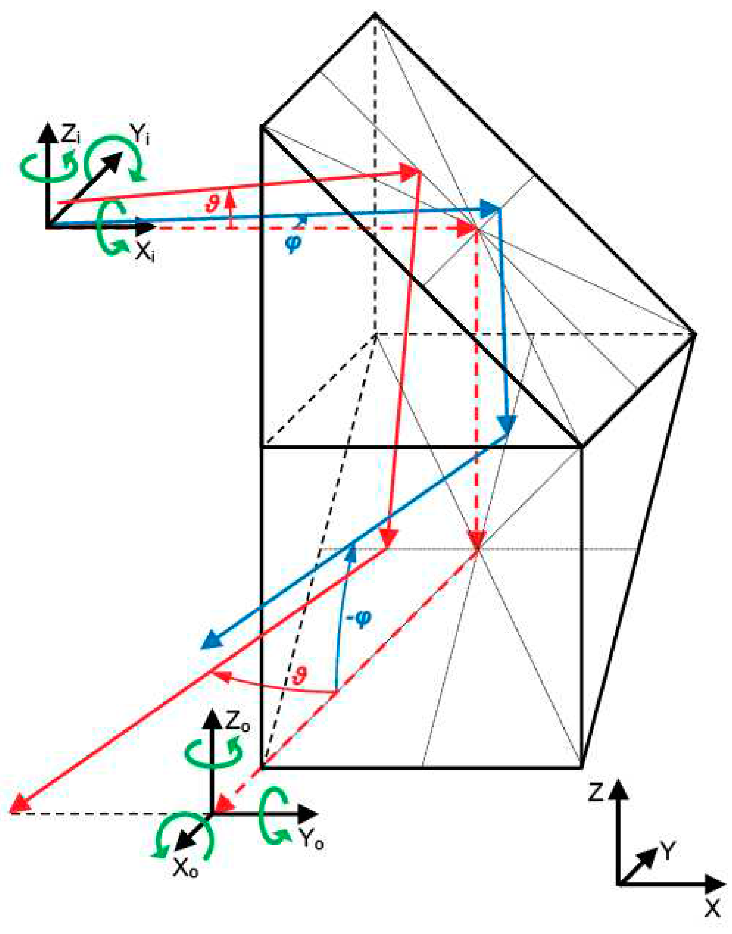
Figure 2.
Setup for two-axial measurement using one mono-axial sensor: P1 and P2 – polarisers, VPR – variable phase retarder, QR – quarter-wave retarder plate, PBS – polarising beamsplitter, NBS – non-polarising beamsplitter, M – mirror, SOE1 – optical element for rotation of beam deflection, SOE2 – optical element for shifting the beam, S – angular sensor. Black arrows show the directions of possible adjustments.
Figure 2.
Setup for two-axial measurement using one mono-axial sensor: P1 and P2 – polarisers, VPR – variable phase retarder, QR – quarter-wave retarder plate, PBS – polarising beamsplitter, NBS – non-polarising beamsplitter, M – mirror, SOE1 – optical element for rotation of beam deflection, SOE2 – optical element for shifting the beam, S – angular sensor. Black arrows show the directions of possible adjustments.
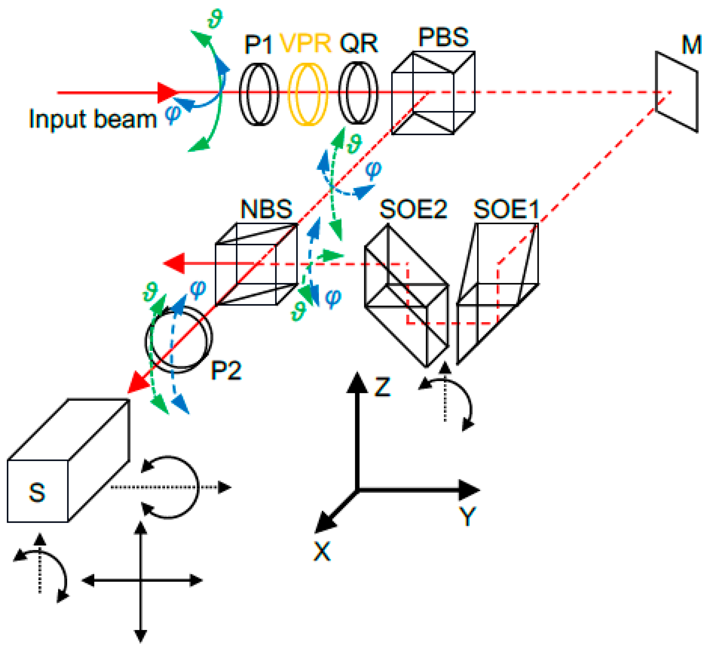
Figure 3.
Principle of operation for the subsystem altering the beam polarisation: P1 – polariser, VPR – variable phase retarder, QR – quarter-wave retarder plate.
Figure 3.
Principle of operation for the subsystem altering the beam polarisation: P1 – polariser, VPR – variable phase retarder, QR – quarter-wave retarder plate.
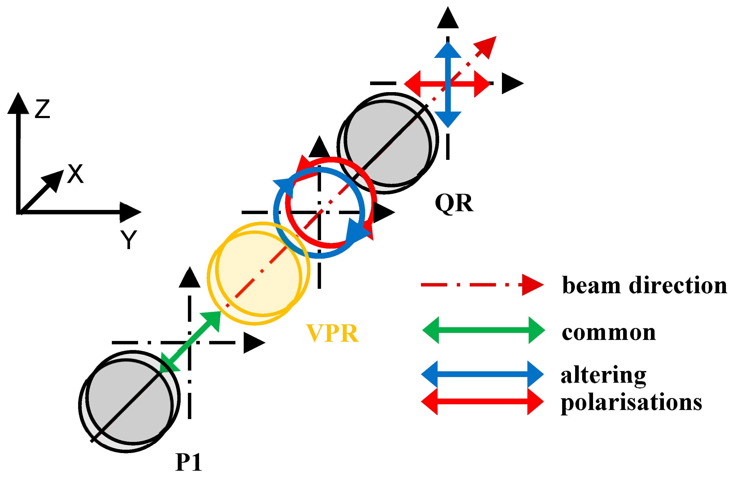
Figure 4.
Main principle of operation of the sensor: PB – polarising beamsplitter, CCR – corner cube reflector, P90 – right-angle prism.
Figure 4.
Main principle of operation of the sensor: PB – polarising beamsplitter, CCR – corner cube reflector, P90 – right-angle prism.
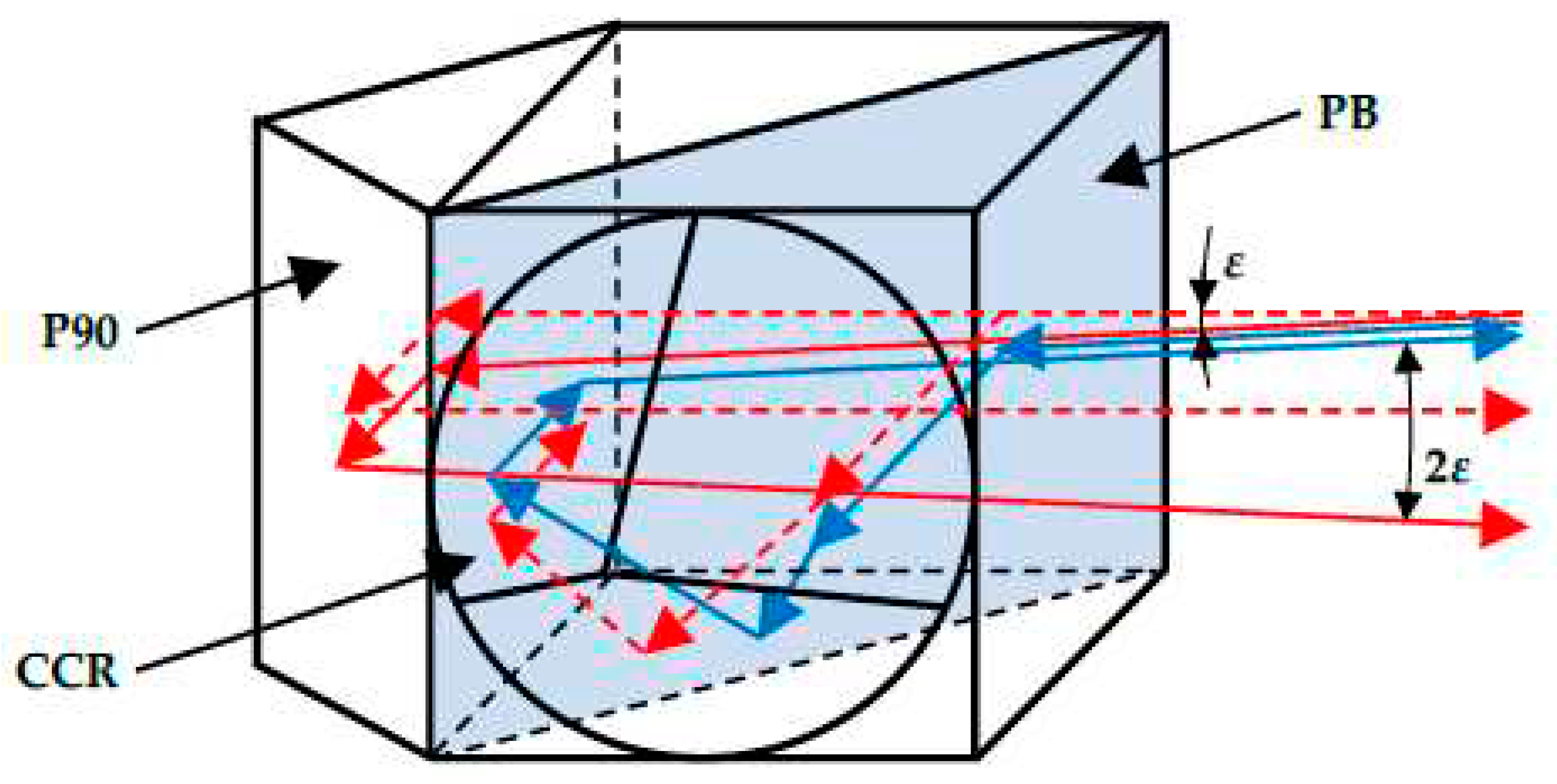
Figure 5.
Setup used for experimental verification of the proposed method: P1 and P2 – polarisers, VPR – variable phase retarder, QR – quarter-wave retarder plate, PBS – polarising beamsplitter, NBS – non-polarising beamsplitter, M – fixed mirror, SOE1 – optical element for rotation of beam deflection, SOE2 – optical element for raising the beam, MM – mirror on piezotranslator controlling the beam.
Figure 5.
Setup used for experimental verification of the proposed method: P1 and P2 – polarisers, VPR – variable phase retarder, QR – quarter-wave retarder plate, PBS – polarising beamsplitter, NBS – non-polarising beamsplitter, M – fixed mirror, SOE1 – optical element for rotation of beam deflection, SOE2 – optical element for raising the beam, MM – mirror on piezotranslator controlling the beam.
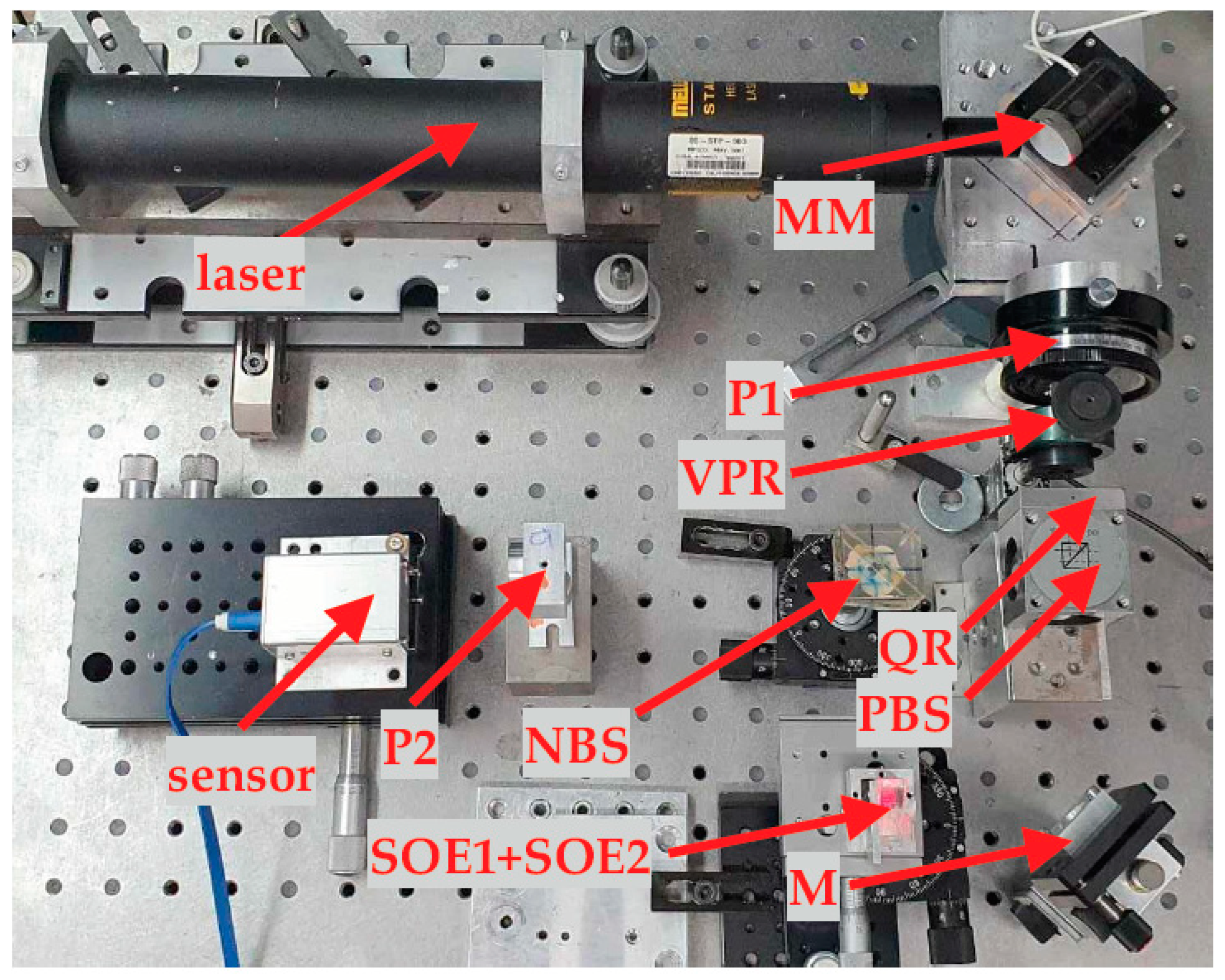
Figure 6.
Results of Experiment 1.
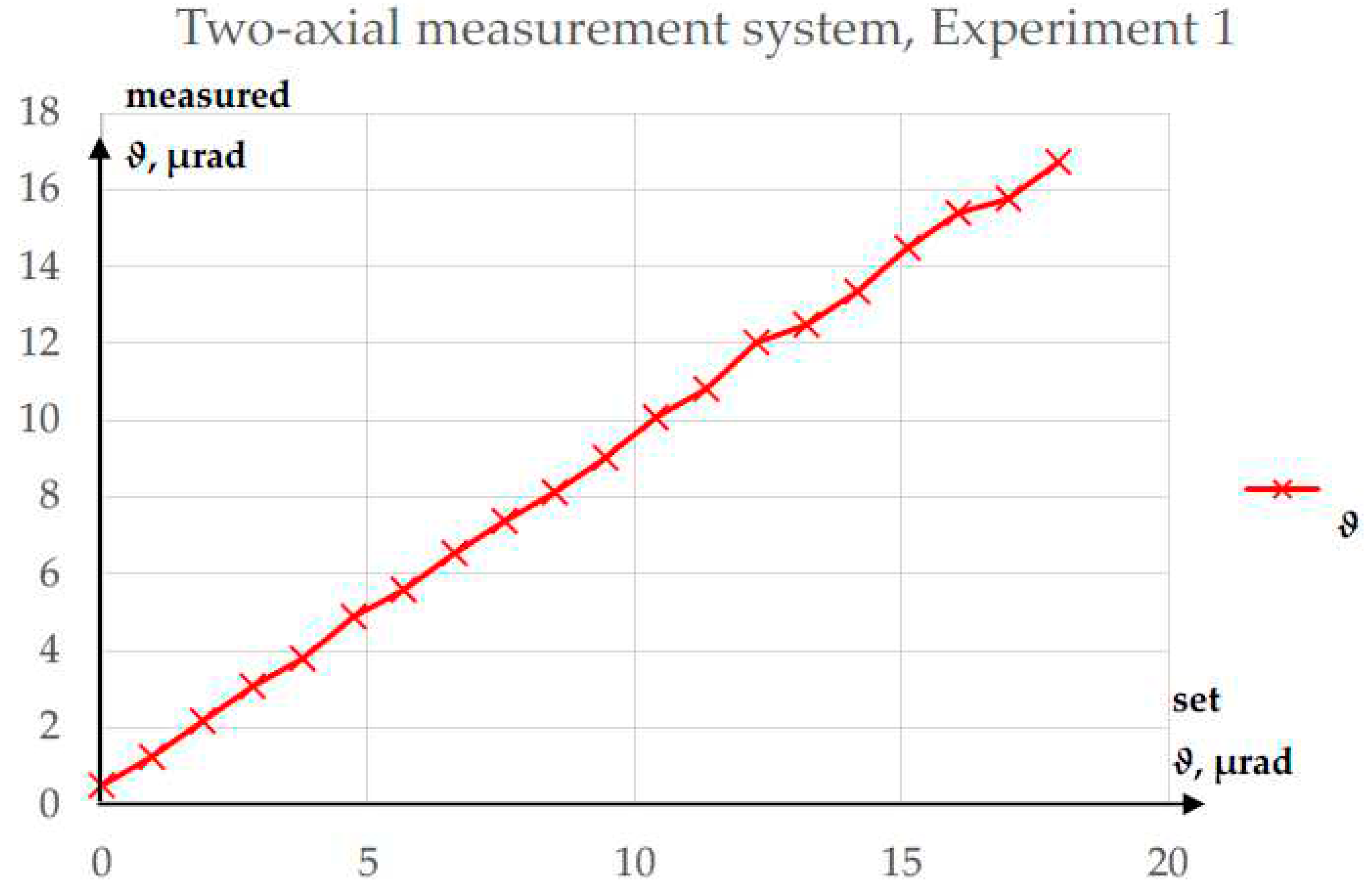
Figure 7.
Results of Experiment 2.
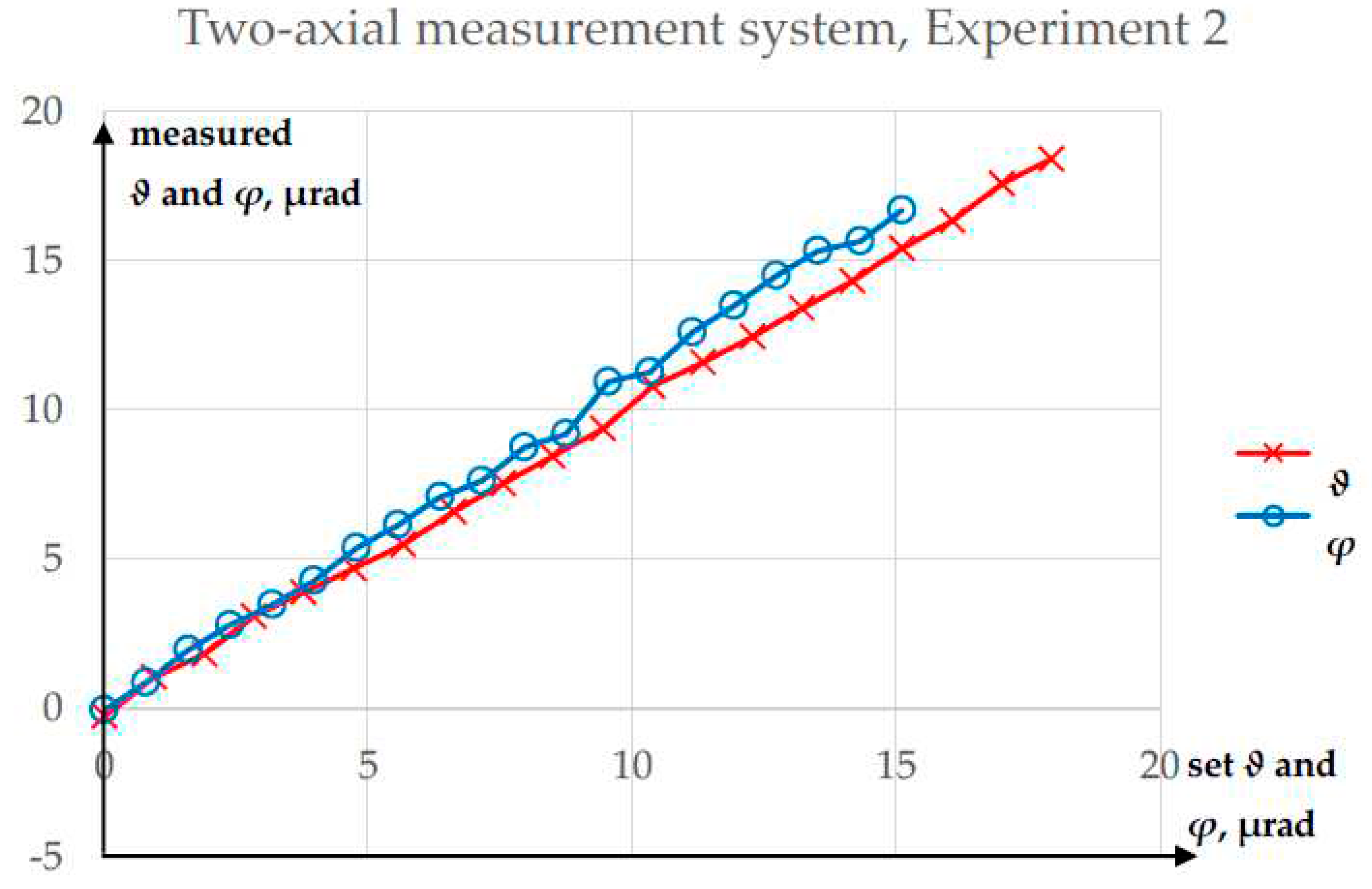
Figure 8.
Results of Experiment 3.
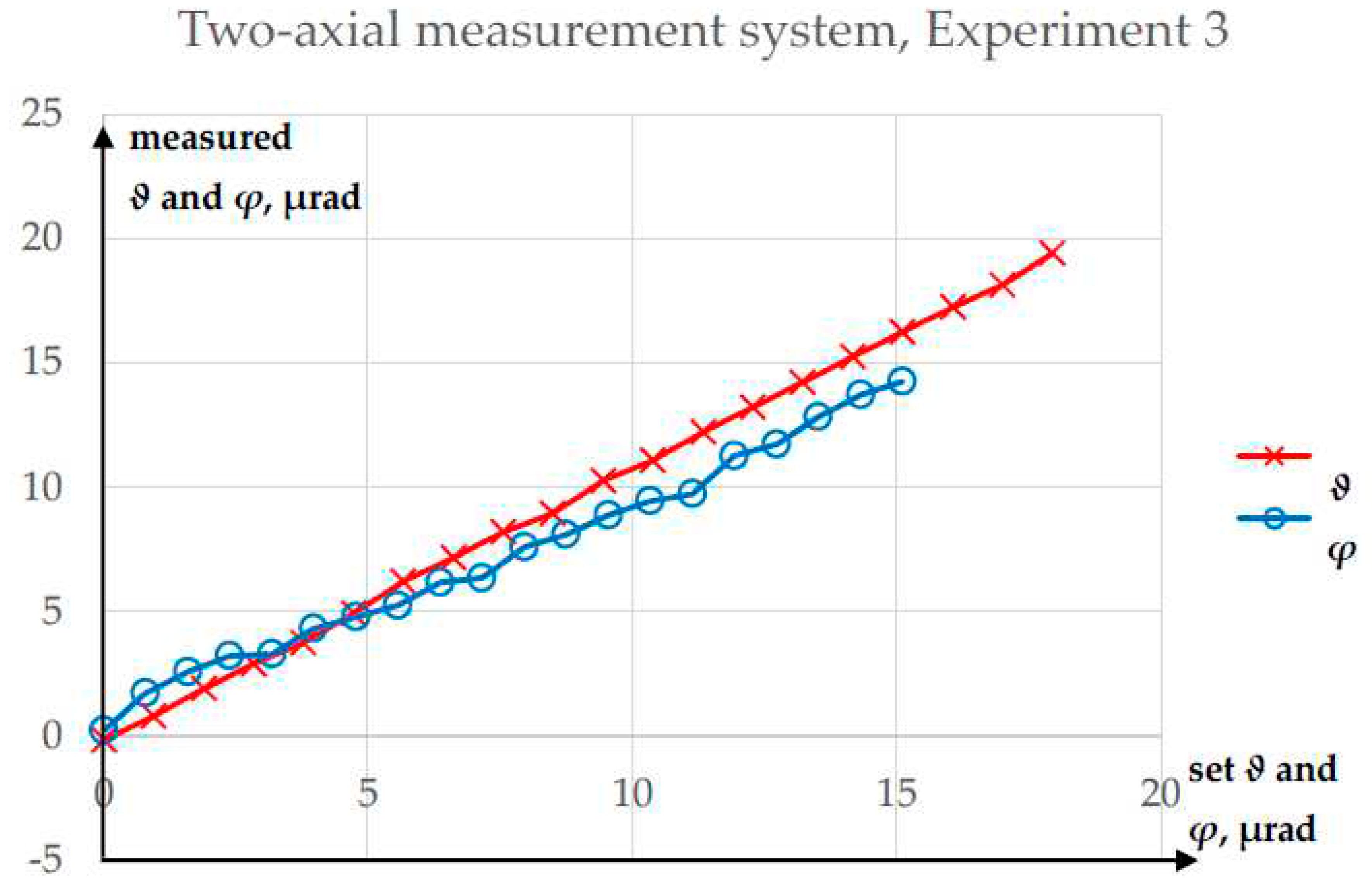
Figure 9.
Results of Experiment 4.

Figure 10.
Comparison of results from Experiments 2, 3, and 4.
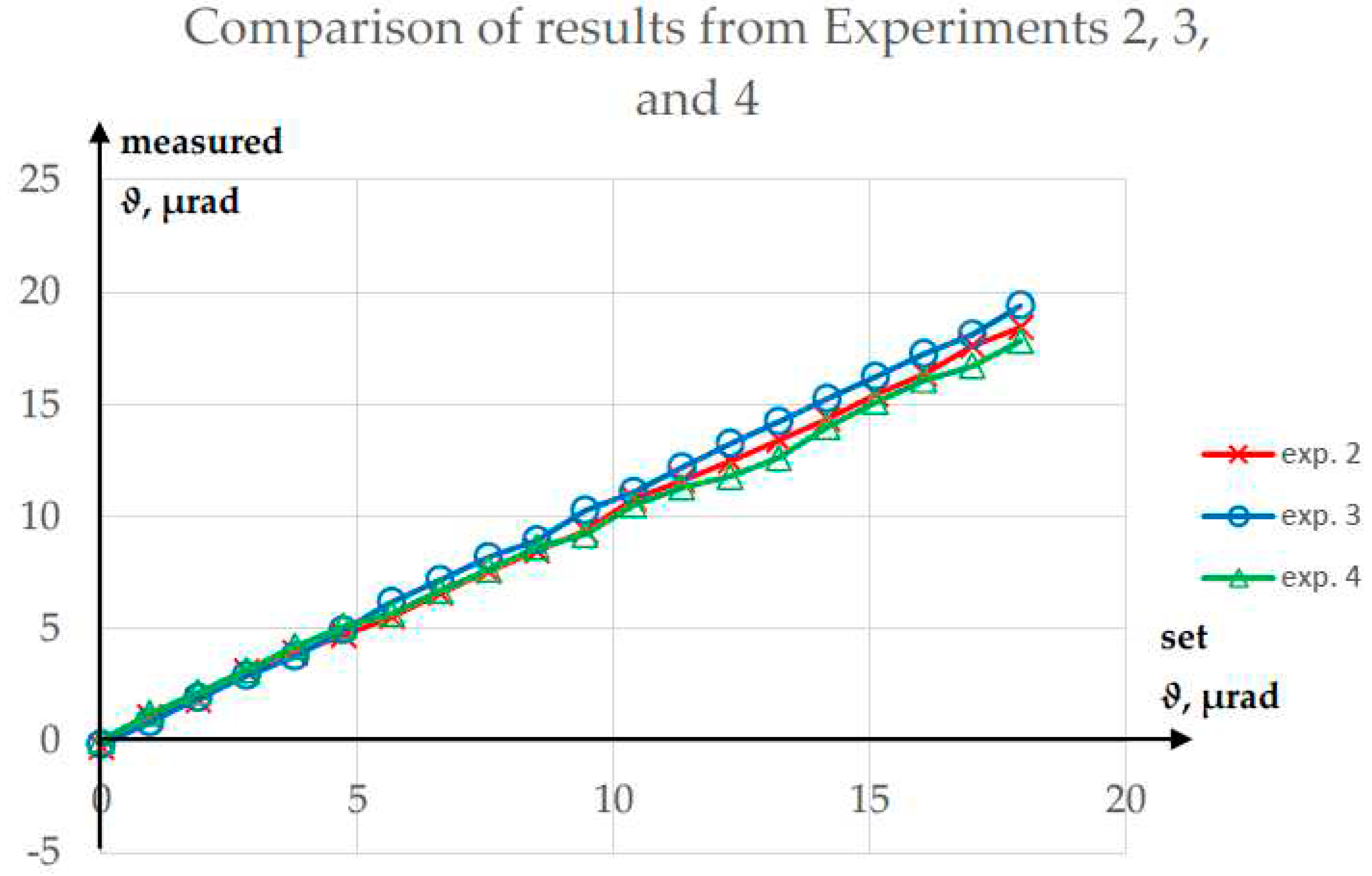
Figure 11.
Results of Experiment 5.
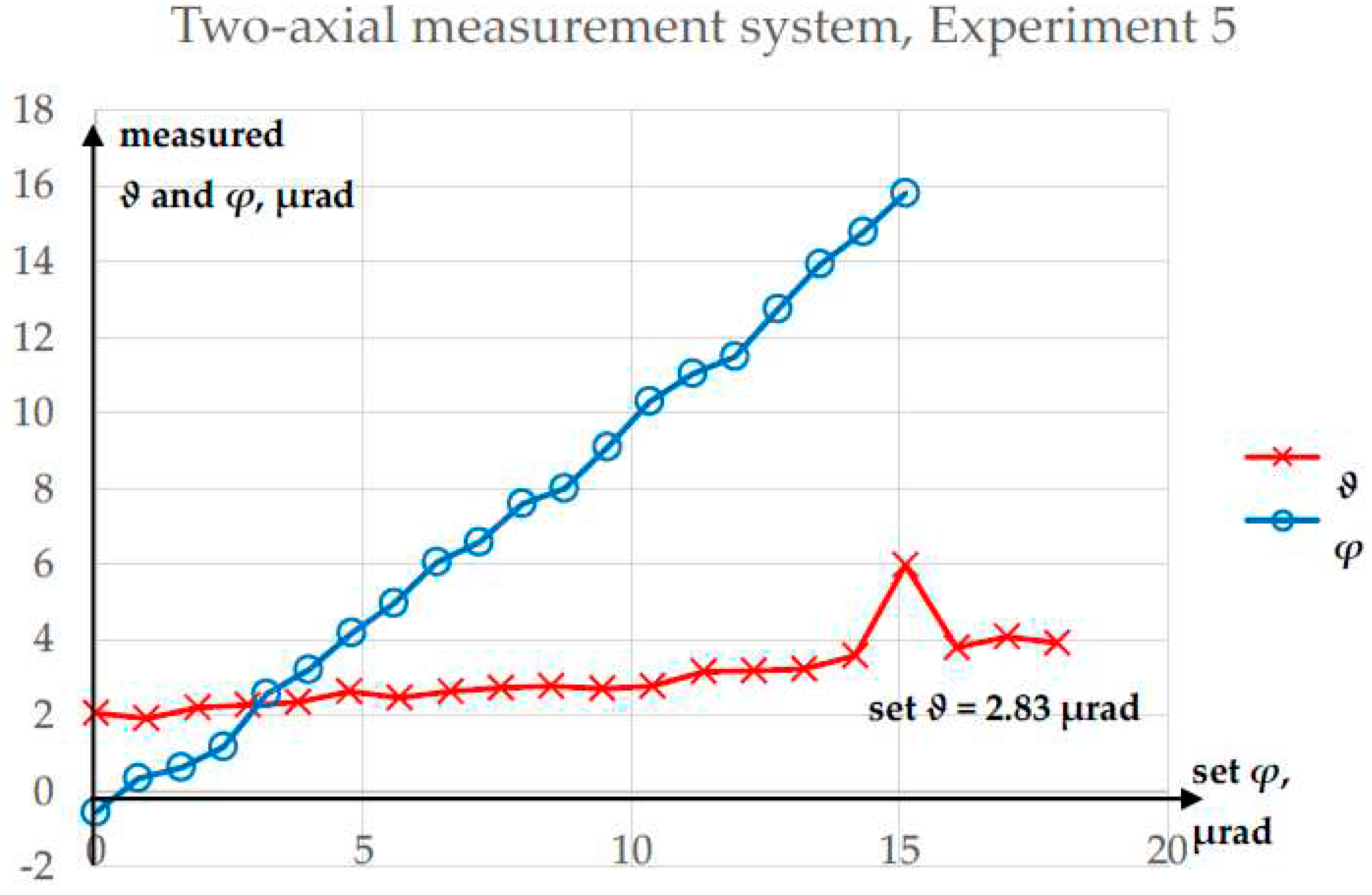
Figure 12.
Comparison of results from Experiments 2, 3, and 5.
Disclaimer/Publisher’s Note: The statements, opinions and data contained in all publications are solely those of the individual author(s) and contributor(s) and not of MDPI and/or the editor(s). MDPI and/or the editor(s) disclaim responsibility for any injury to people or property resulting from any ideas, methods, instructions or products referred to in the. |
© 2023 by the authors. Licensee MDPI, Basel, Switzerland. This article is an open access article distributed under the terms and conditions of the Creative Commons Attribution (CC BY) license (http://creativecommons.org/licenses/by/4.0/).
Copyright: This open access article is published under a Creative Commons CC BY 4.0 license, which permit the free download, distribution, and reuse, provided that the author and preprint are cited in any reuse.


