
Submitted:
10 October 2023
Posted:
11 October 2023
You are already at the latest version
Abstract
The demand for high-energy-density batteries necessitates novel anode materials. Transition metal oxides (TMOs) show promise due to their high capacity, sustainability, and cost-effectiveness. However, TMO-based anodes face challenges related to expansion and conductivity. This study presents a two-step dilution crystallization method to fabricate porous ZnO nanoflowers at a moderate temperature. In-situ integration with carbon nanotube dispersants enhances conductivity and reduces agglomeration. The resulting composite anode exhibits impressive initial discharge capacity (2314.2 mAh g-1) and cycling stability (580.5 mAh g-1 over 50 cycles). This study provides a facile approach for next-generation anode materials.
Keywords:
ZnO anodes
; nanoflowers
; CNT dispersants
; electrical conduction network
; lithium-ion batteries
1. Introduction
Extensive efforts have been devoted to advancing lithium-ion batteries (LIBs) due to their superior energy density, prolonged cyclic lifespan, and eco-friendliness [1-3]. However, the demand for LIBs with higher energy density in practical applications necessitates exploring alternative anode materials [4, 5]. Transition-metal-oxide (TMO)-based anodes, such as ZnO, have gained attention due to their high theoretical capacity and low costs. Despite its advantages, bulk ZnO faces challenges of sluggish kinetics and poor cycling stability which primarily due to volumetric expansion during lithiation and delithiation processes [6-8].
To address these limitations, researchers have explored strategies including morphology control and nanostructure design. Nanoscale structural design plays a pivotal role in achieving optimal anode performance by mitigating volume expansion and shortening the electron transfer path [9-11]. Increasing the surface area and pore density of anode materials promotes enhanced contact between the electrolyte and anode, facilitating the formation of a stable solid electrolyte interface (SEI) and improving electrochemical properties [12-14]. Additionally, integrating carbon-based materials like carbon nanotubes (CNTs) with ZnO anodes has been shown to enhance electrochemical performance by forming an electron conductive network and providing a cushion against volume expansion [15].
However, the synthesis of ZnO nanostructures has relied on complex methods, and the preparation of composite anodes poses challenges for commercialization. In this study, we present a facile two-step dilution crystallization method for synthesizing hierarchical ZnO nanoflowers (ZONFs) at a low temperature. The ZONFs are combined with CNT dispersants to in-situ form the ZONF-CNT composite, offering a simplified approach compared to conventional methods. The flower-like morphology enhances the contact area between the anode and electrolyte, promoting a stable SEI and favorable cyclic performance. The inclusion of CNTs dispersants prevents aggregation and improves cyclic stability. Moreover, the presence of CNTs establishes an electrically conductive network, enhancing the charge transfer. Overall, the ZONF-CNT composite demonstrates exceptional electrochemical performance, making it highly desirable for efficient energy storage devices.
The introduction should briefly place the study in a broad context and highlight why it is important. It should define the purpose of the work and its significance. The current state of the research field should be carefully reviewed and key publications cited. Please highlight controversial and diverging hypotheses when necessary. Finally, briefly mention the main aim of the work and highlight the principal conclusions. As far as possible, please keep the introduction comprehensible to scientists outside your particular field of research. References should be numbered in order of appearance and indicated by a numeral or numerals in square brackets—e.g., [1] or [2,3], or [4,5,6]. See the end of the document for further details on references.
2. Materials and Methods
2.1. Material preparation
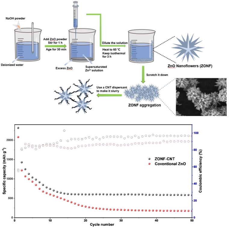
The schematic representation of the synthesis process for ZnO nanoflowers (ZONFs) and the preparation of the ZONF-CNT composite slurry is illustrated in Figure 1(a). All chemicals used in the experiment are of analytical grade, and the deionized water employed has a resistivity over 18.5 MΩ cm-1. Initially, a solution of 4 mol L-1 was prepared by dissolving 35.2 g of NaOH in 215 mL of deionized water. Subsequently, 6 g of ZnO was gradually added to the solution while stirring for approximately 1 hour, resulting in a homogeneous and partially transparent Zn2+ supersaturated solution. The beaker containing the solution was then placed on a flat platform and allowed to age for 30 minutes. Afterward, each 100 mL of the supersaturated solution was mixed with 900 mL of deionized water to obtain a diluted solution. The diluted solution was then heated at 60 ℃ for 3 hours. During this process, a white precipitate formed and settled at the bottom of the beaker, which was later collected by scraping it off using a scraper. The precipitate was separated from the solution by filtration, washed multiple times with deionized water, and subsequently dried in a vacuum oven at 160 ℃ for 8 hours to prevent the formation of zinc oxide hydrate. Finally, ZONFs were mixed with carbon black, and polyvinylidene fluoride, and a commercial CNT dispersant to form slurry.
2.2. Material characterization
To evaluate the crystalline structure, morphology, and composition of ZONFs, several characterization tools were employed, including X-ray diffractometry (XRD, Rigaku RINT 2400) with Cu Kɑ radiation, Raman spectroscopy (HORIBA Jobin Yvon, Tokyo, Japan), scanning electron microscopy (SEM, JSM 6490LV), and transmission electron microscopy (TEM, JEM-2100&Aztec Energy TEM SP X-MaxN 80T).
2.3. Electrochemical measurement
The electrochemical measurements were conducted using CR2016 type coin cells, with ZONF-CNT (or conventional ZnO) anodes serving as the working anode, and Li metal foils utilized as the counter anode and reference anode. All half cells were assembled within an argon-filled glove box to maintain a controlled environment, with water and oxygen contents both below 0.01 ppm. The synthesis of ZONF-CNT anodes involved the following steps: Slurries were prepared by stirring a mixture of 2.8 g active material powders, 0.8 g carbon black and 0.4 g polyvinylidene fluoride (PVDF) in a 4 mL commercial CNT dispersant (95 wt% N-Methylpyrrolidone (NMP), ~4.5 wt% CNT, and 0.5 wt% dispersant) for 12 hours. The resulting slurry was then meticulously casted directly onto the rough surface of a copper foil (9 µm thick) using a coating machine, followed by drying at 80 ℃ for 15 minutes. Subsequently, the foils were dried in a vacuum at 120 ℃ for 12 hours. The working anodes were then punched out from the dried casting foil. For the conventional ZnO anodes, the same process was followed, except that commercial ZnO powder was used as the active material, and pure NMP was employed as the solvent instead of the CNT dispersant. Other components of each half cell included a Celgard 2400 separator and a 1 M LiPF6 electrolyte with a 1:1:1 volume ratio of ethylene carbonate (EC), diethyl carbonate (DEC), and dimethyl carbonate (DMC). The areal loading mass for ZnO anodes and ZONF-CNT anodes is 3.2 mg cm-2.
The constant current charge/discharge tests were carried out using a LANBTS-BT2018R battery test system (Wuhan, China), with the cut-off potential window ranging from 0.05 to 2.5 V vs. Li+/Li. The current densities of galvanostatic tests were figured out based on areal loading mass and specific capacities of ZnO (1C=978 mAh g-1). The electrochemical workstation (Gamry Interface 1010E) was employed to determine the electrochemical impedance spectroscopy (EIS, 100 kHz–0.01Hz) and the cyclic voltammograms (CVs) at various scanning rates ranging from 0.01 to 1 mV s-1. The Li+ diffusion coefficient was figured out by using the chemical coefficient formula [16], which is based on the CV data.
3. Results
The crystal structure of the ZONFs was investigated by the powder XRD (Figure 1(b)). All the main peaks are well agreed with the Bragg’s reflections of the standard wurtzite ZnO structure (JCPDS Card No.36-1451) with lattice constants a = b = 3.24 Å and c = 5.21 Å 17. To further confirm the structure of the as-prepared sample, the Raman spectroscopy was conducted, as shown in Figure 1(c). The major peaks are mainly in the range from 250 to 500 cm-1 with a characteristic peak located at about 438 cm-1 that is ascribed to the E2 vibration of ZnO, verifying the hexagonal structure of as-prepared powders [18].
The morphology of the synthesized ZONFs was characterized using scanning electron microscopy (SEM). As shown in Figure 2(a), the SEM image reveals a uniform distribution of hierarchical ZnO nanoflowers. It is observed that the nanoflowers possess ample space between them, which serves two important functions: firstly, it can accommodate potential expansion of ZnO during the charging-discharging process, and secondly, it provides multiple pathways for the diffusion of Li ions. At higher magnifications (Figures 2(b) and 2(c)), it can be observed that each hierarchical flower structure is composed of numerous nano-spines, significantly increasing the contact area with the electrolyte and facilitating the formation of a stable solid SEI layer. The diameter distribution of the ZnO nanoflowers was analyzed and plotted as shown in Figure 2(d), indicating that the majority of the nanoflowers exhibit diameters in the range of 3-6 µm.
The elemental mapping analysis of the ZONFs was conducted using Energy-Dispersive X-ray Spectroscopy (EDS), and the results are presented in Figures 2(e)-2(g). As anticipated, the distribution of the Zn and O elements on the surface of the nanoflowers is found to be uniform, confirming the expected composition of ZnO. Additionally, a carbon signal is observed in the EDS maps, which originates from the conductive carbon resin used for sample fixation on the platform. Figure 2(h) displays a representative EDS spectrum of the ZONFs, revealing prominent peaks corresponding to Zn and O elements. The absence of any other significant peaks in the spectrum further supports the conclusion that the final product obtained is pure ZnO.
Transmission Electron Microscopy (TEM) was employed to gain insights into the detailed structure of the synthesized ZnO nanoflowers. Figure 2(i) presents the overall structure of a representative flower, with a diameter of approximately 3 µm. The hierarchical architecture exhibits numerous spines protruding from a central core. At higher magnification, two individual spines are clearly visible in Figure 2(j). The formation of these spines can be attributed to the influence of surface energy during the synthesis process of ZONFs. To further elucidate the crystal structure, High-Resolution TEM (HRTEM) imaging and corresponding Selected Area Electron Diffraction (SAED) patterns of the ZONFs are displayed in Figure 2(k) and 2(l), respectively. The lattice spacings observed in the HRTEM image, namely 0.26 nm and 0.25 nm corresponding to the (002) and (101) planes of ZnO wurtzite structure, respectively, indicate a polycrystalline nature of the as-prepared ZONFs, which is further confirmed by Figure 2(l). The presence of isotropic polycrystals is advantageous in terms of improved resilience during the charging-discharging process, as compared to single crystals [11]. Moreover, the flower-like morphology, in contrast to other nanostructures such as nanorods or nanosheets, offers a significantly larger contact area with the electrolyte, thereby facilitating the formation of a stable SEI and enhancing the reaction kinetics, ultimately reducing the polarization effect.
The electrochemical performance of the ZONF-CNT anode for LIBs was evaluated carefully with half-cells assembled with Li metal as counter anodes. From the previous report [19], the Li+ insertion and extraction in the anode can be generally demonstrated by the following equations:
2Li+ + ZnO +2e- = Li2O + Zn
Zn + xLi+ + xe- = LixZn
Cyclic Voltammetry (CV) measurements were conducted on the ZONF-CNT anode in the voltage range of 0.05-2.5 V (vs. Li+/Li) at a scan rate of 0.2 mV s-1. The CV profiles depicted in Figure 3(a) represent the electrochemical reactions during the charging and discharging processes in the cell. During the first cathodic scan of the ZONF-CNT, a distinct peak was observed at approximately 0.24 V, which subsequently shifted to a potential of 0.62 V in the subsequent cycles. This phenomenon primarily arises from the reduction of Zn2+ to Zn, the formation of LiZn, and the generation of a Solid Electrolyte Interface (SEI) layer, which may contribute to a partial loss in irreversible capacity 20. During the anodic scanning process, five characteristic peaks at 0.36, 0.54, 0.70, 1.67, and 2.58 V were identified. The first three peaks are attributed to the multi-step de-alloying process of lithium-zinc alloys, such as LiZn, LiZn2, Li2Zn3, and Li2Zn5, along with the decomposition of the SEI layer [21]. The sharp anodic peak observed at 1.67 V can be attributed to the inverse conversion of Zn and Li2O into ZnO [22], while the 2.58 V peak is likely associated with the slight oxidation of residual dispersant, which almost disappears in the subsequent cycles. In the subsequent scans, the CV curves exhibit a high degree of overlap, indicating the excellent reversibility of the ZONF-CNT anode.
The discharge/charge profiles of the ZONF-CNT anode and the conventional ZnO anode were evaluated in the potential range of 0.05-2.5 V (vs. Li/Li+) at a current density of 0.5C. Figures 3(b) and 3(c) illustrate the charge-discharge behaviors of the ZONF-CNT and conventional ZnO anodes during the initial three full cycles. In Figure 3(b), the ZONF-CNT anode exhibits a discharge capacity of 2314.2 mAh g-1 during the first cycle, with a corresponding coulombic efficiency (CE) of 56.7%. It should be noted that the initial discharge capacity is significantly higher than the initial charge capacity due to an unidentified activation process [23]. In the 2nd and 3rd cycles, the CE improves to 80.5% and 82.5%, respectively, indicating a reduced formation of the SEI film and LiZn alloy in subsequent electrochemical processes, thus demonstrating enhanced cyclic stability. Despite the considerable capacity loss observed in the first two cycles, the ZONF-CNT anode still maintains a substantial specific capacity of 1249.8 mAh g-1 in the 3rd cycle, surpassing the theoretical capacity (372 mAh g-1) of commercial graphite anodes. For comparison, the discharge/charge profiles of the conventional ZnO anode in the potential window of 0.05-2.5 V (vs. Li/Li+) were also investigated, as presented in Figure 3(c). The conventional ZnO anode exhibits a relatively lower discharge capacity of 1066.3 mAh g-1 in the 3rd cycle, although it demonstrates good CE in the initial three cycles.
The cycling performance of the ZONF-CNT anode and the conventional ZnO anode was assessed, as presented in Figure 3(e), in a potential range of 0.05 to 2.5 V at a current density of 0.5C. In the first cycle, the conventional ZnO anode exhibits a discharge capacity of 2079.9 mAh g-1, whereas the ZONF-CNT anode demonstrates a significantly higher discharge capacity of 2314.2 mAh g-1. These relatively high capacities in the first cycle can be attributed to the formation of Li-zinc alloy and subsequent conversion of ZnO to Zn [24]. Both the conventional ZnO and ZONF-CNT anodes exhibit notable reversible capacities at a high current density during the initial cycles. Moreover, the ZONF-CNT anode exhibits nearly twice the capacity of the conventional ZnO anode after 20 cycles. The superior rate and capacity performance of the ZONF-CNT anode can be attributed to the formation of a stable conductive network between the ZnO nanoflowers and the CNT, which effectively prevents the aggregation of active materials. Consequently, the discharge capacity of the ZONF-CNT anode stabilizes after 15 cycles, while the performance of the conventional ZnO anode continues to deteriorate until the 30th cycle. Significantly, the stable ZONF-CNT anode can be cycled for up to 50 cycles, maintaining a capacity of approximately 580.5 mAh g-1, which greatly exceeds the theoretical capacity of graphite.
To gain deeper insights into the mechanism of the ZONF-CNT and conventional ZnO anodes, potentiostatic electrochemical impedance spectroscopy (EIS) analysis was conducted. Figure 3(d) presents the Nyquist curves of the ZONF-CNT and conventional ZnO anodes after 15 cycles, covering a frequency range of 100 kHz to 10 MHz with an amplitude of 5 mV. As depicted in Figure 3(e), the diameter of the depressed semicircles in the high-frequency region corresponds to the charge transfer resistance, denoted as Rct [25]. Notably, the Rct value of the ZONF-CNT anode is significantly lower than that of the conventional ZnO anode. This can be attributed to the conductive nature of the CNTs enveloping each ZnO nanoflower, which provides multiple electron pathways for the charging and discharging processes. Furthermore, the EIS curve of the conventional ZnO anode exhibits a minor semicircle between the high and low-frequency regions, indicating the presence of an interface layer resistance that influences the rate performance. Consequently, owing to the hierarchical nano-flower structure and the incorporation of CNTs, the ZONF-CNT anode exhibits considerably lower resistance compared to the conventional ZnO anode. This hierarchical structure and CNT combination facilitate multi-pathways for Li-ion transport and electron conduction, respectively [26].
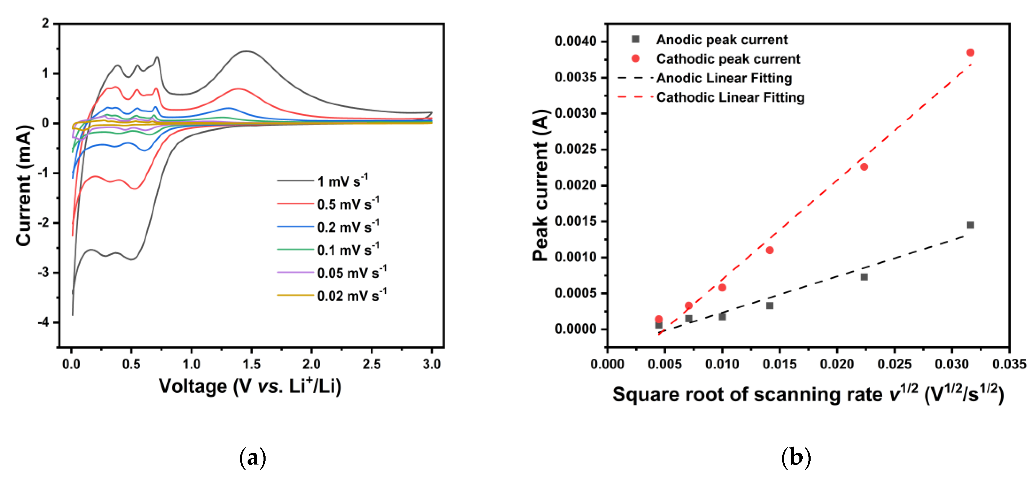
In general, four approaches are applied to figure out the Li+ diffusion coefficient, including EIS, CV, potentiostatic intermittent titration technique (PITT) and Galvanostatic intermittent titration technique (GITT). Because of its accuracy, herein the CV method was adapted and the results at different scanning rates are presented in Figure 4(a). The equation to calculate the Li+ diffusion coefficient is shown below [16]:
where Ip denotes the peak current (in Ampere), n is the charge-transfer number, A represents the surface area (in cm2) of the anode, DLi is the chemical diffusion coefficient for Li+, F is the Faraday constant, R is the gas constant, T is the absolute temperature, ΔCo factor shows the bulk concentration of Li-ion in the anode (i.e., 0.168 mol/cm3), and v denotes the scanning rate of CV. At room temperature, Eq. (3) can be simplified as follows:
IP = 0.4463nFA[nF/(RT)]1/2 ΔCo (DLi)1/2 v 1/2
IP = 2.69 x 10⁵ n1/2A ΔCo (DLi)1/2 v 1/2
Based on Eq. (4), the relationship between the peak current and the square root of the scanning rate can be figured out and is shown in Figure 4(b), where the slope of the linear fitting can be used to calculate DLi directly. The Li+ diffusion coefficient DLi is calculated to be in the range of 3.227 ⨯ 10-13 to 2.432 ⨯ 10-12 cm2 s -1, which is even higher than that of other excellent ZnO-based anodes like hybrid ZnO/Si/porous-carbon anode [27]. The faster Li+ diffusion is ascribed to the hierarchical and porous structure of as-prepared nanoflowers and the synergistic function of CNTs which can not only form an electron conductive network around active materials but also prevent them from aggregating and pulverizing. As a result, both low electron charge-transfer resistance Rct and high Li+ diffusion coefficient DLi have been realized, suggesting that the ZONF-CNT composite owns a superior advantage in charge transfer.
5. Conclusions
In conclusion, we have successfully developed a facile two-step dilution crystallization method to synthesize hierarchical and porous ZnO nanoflowers (ZONFs) at a low temperature of 60 ℃. These as-prepared ZONFs can be easily combined with a CNT dispersant to in-situ create a high-capacity ZONF-CNT composite anode. Remarkably, the resulting composite anode exhibits an impressive initial discharge capacity of 2314.2 mAh g-1 at a current density of 0.5C. Moreover, it demonstrates exceptional cycling stability over 50 cycles, maintaining a discharge capacity of 580.5 mAh g-1, surpassing the theoretical capacity of conventional graphite anodes. Additionally, the composite anode exhibits a high Li+ diffusion coefficient DLi, ranging from 3.227 ⨯ 10-13 to 2.432 ⨯ 10-12 cm2 s -1 cm2 s -1, surpassing that of other reported excellent ZnO-based anodes. The outstanding performance of the ZONF-CNT composite anode can be attributed to the unique hierarchical ZnO nano-flower structure and the functional role played by CNTs, including the formation of a conductive network and prevention of ZONF agglomeration. These findings demonstrate the significant potential of the synthesized ZnO composite as promising anode materials for lithium-ion batteries.
Author Contributions
Conceptualization, Gangqiang Peng; Methodology, Gangqiang Peng; Experiments, Gangqiang Peng; Data curation and Formal analysis, Gangqiang Peng; Writing, Fude Liu, Gangqiang Peng; Editing, Abdur Rauf and Guohong Wang; Assisting experiments, Qiangfeng Zheng; Review, Guohong Wang, Dawei Zheng, Ubaid Khan, Fude Liu and Abdul Rehman Akbar; Instruction for paper writing, Shan Feng. Funding acquisition, Fude Liu. All authors have read and agreed to the published version of the manuscript.
Funding
This research was funded by the Peacock Plan Research Fund [Project Code 000580] and Startup Fund for Distinguished Professorship [Project Code 0000021259]
Data Availability Statement
The data presented in this study are available on request from the corresponding author.
Acknowledgments
This work was supported by the Peacock Plan Research Fund [Project Code 000580] and Startup Fund for Distinguished Professorship [Project Code 0000021259]
Conflicts of Interest
The authors declare no conflict of interest.
References
- J. Xu, J. Ma, Q. Fan, S. Guo and S. Dou: Recent Progress in the Design of Advanced Cathode Materials and Battery Models for High-Performance Lithium-X (X = O(2) , S, Se, Te, I(2) , Br(2) ) Batteries. Adv. Mater. 2017, 29, 1606454. [CrossRef]
- X. Duan, J. Xu, Z. Wei, J. Ma, S. Guo, H. Liu and S. Dou: Atomically Thin Transition-Metal Dichalcogenides for Electrocatalysis and Energy Storage. Small Methods 2017, 1, 1700156. [CrossRef]
- L. Wang, Z. Yang, X. Chen, H. Qin and P. Yan: Formation of porous ZnO microspheres and its application as anode material with superior cycle stability in zinc-nickel secondary batteries. J. Power Sources 2018, 396, 615. [CrossRef]
- Q. Zhao, H. Xie, H. Ning, J. Liu, H. Zhang, L. Wang, X. Wang, Y. Zhu, S. Li and M. Wu: Intercalating petroleum asphalt into electrospun ZnO/Carbon nanofibers as enhanced free-standing anode for lithium-ion batteries. J. Alloys Compd. 2018, 737, 330. [CrossRef]
- H. liu, L. Shi, D. Li, J. Yu, H.-M. Zhang, S. Ullah, B. Yang, C. Li, C. Zhu and J. Xu: Rational design of hierarchical ZnO@Carbon nanoflower for high performance lithium ion battery anodes. J. Power Sources 2018, 387, 64. [CrossRef]
- Q. Zhao, H. Xie, H. Ning, J. Liu, H. Zhang, L. Wang, X. Wang, Y. Zhu, S. Li, M.J.J.o.A. Wu and Compounds: Intercalating petroleum asphalt into electrospun ZnO/Carbon nanofibers as enhanced free-standing anode for lithium-ion batteries. J. Alloys Compd. 2018, 737, 330. [CrossRef]
- Y. Zhao, G. Huang, Y. Li, R. Edy, P. Gao, H. Tang, Z. Bao and Y.J.J.o.M.C.A. Mei: Three-dimensional carbon/ZnO nanomembrane foam as an anode for lithium-ion battery with long-life and high areal capacity. J. Mater. Chem. 2018, 6, 7227. [CrossRef]
- H. Tan, H.-W. Cho and J.-J. Wu: Binder-free ZnO@ZnSnO3 quantum dots core-shell nanorod array anodes for lithium-ion batteries. J. Power Sources 2018, 388, 11. [CrossRef]
- L. Wang, K. Tang, M. Zhang and J. Xu: Facile Synthesis of Mn-Doped ZnO Porous Nanosheets as Anode Materials for Lithium Ion Batteries with a Better Cycle Durability. Nanoscale Res. Lett. 2015, 10, 983.
- H. Li, Z. Liu, S. Yang, Y. Zhao, Y. Feng, Z. Bakenov, C. Zhang and F. Yin: Facile Synthesis of ZnO Nanoparticles on Nitrogen-Doped Carbon Nanotubes as High-Performance Anode Material for Lithium-Ion Batteries. Materials 2017, 10, 1102. [CrossRef] [PubMed]
- D. Kim, S.H.R. Shin, Y. Kim, K. Crossley, Y. Kim, H. Han and J. Yoo: Hierarchical assembly of ZnO nanowire trunks decorated with ZnO nanosheets for lithium ion battery anodes. RSC Adv. 2020, 10, 13655. [CrossRef]
- J. Cui, F. Cheng, J. Lin, J. Yang, K. Jiang, Z. Wen and J.J.P.T. Sun: High surface area C/SiO2 composites from rice husks as a high-performance anode for lithium ion batteries. Powder Technol. 2017, 311, 1. [CrossRef]
- Y.D.S. Pambudi, R. Setiabudy, A.H. Yuwono, E. Kartini, J.K. Lee and C. Hudaya: Effects of annealing temperature on the electrochemical characteristics of ZnO microrods as anode materials of lithium-ion battery using chemical bath deposition. Ionics 2018, 25, 457.
- J. Yan, P. Xu, S. Chen, G. Wang, F. Zhang, W. Zhao, Z. Zhang, Z. Deng, M. Xu and J.J.E.A. Yun: Construction of highly ordered ZnO microrod@ SnO2 nanowire heterojunction hybrid with a test-tube brush-like structure for high performance lithium-ion batteries: experimental and theoretical study. Electrochim. Acta 2020, 330, 135312.
- D. Wang, J. Guo, C. Cui, J. Ma and A.J.M.R.B. Cao: Controllable synthesis of CNT@ ZnO composites with enhanced electrochemical properties for lithium-ion battery. Mater. Res. Bull. 2018, 101, 305. [CrossRef]
- W. Huang, J. Peng, J. Li, X. Hou, X. Zhang and Z.J.I. Fang: Diffusion coefficient analysis of aluminum electrolysis spent cathode as anode material for lithium-ion battery. Ionics 2022, 1.
- M. Nabil, I. Perez-Quintana, M. Acosta, J. Mendez-Gamboa, R.J.A.i.M.S. Castro-Rodriguez and Engineering: Morphological, Structural, and Optical Bandgap Characterization of Extracted ZnO Nanoparticles from Commercial Paste. Adv. Mater. Sci. Eng. 2021, 2021.
- M. Taufique, A. Haque, P. Karnati and K.J.J.o.E.M. Ghosh: ZnO–CuO nanocomposites with improved photocatalytic activity for environmental and energy applications. J. Electron. Mater. 2018, 47, 6731. [CrossRef]
- L. Wang, X. Gu, L. Zhao, B. Wang, C. Jia, J. Xu, Y. Zhao and J.J.E.A. Zhang: ZnO@ TiO2 heterostructure arrays/carbon cloth by charge redistribution enhances performance in flexible anode for Li ion batteries. Electrochim. Acta 2019, 295, 107. [CrossRef]
- L. Xiao, E. Li, J. Yi, W. Meng, S. Wang, B. Deng, J.J.J.o.A. Liu and Compounds: Enhancing the performance of nanostructured ZnO as an anode material for lithium-ion batteries by polydopamine-derived carbon coating and confined crystallization. J. Alloys Compd. 2018, 764, 545. [CrossRef]
- L. Shi, D. Li, J. Yu, H.-M. Zhang, S. Ullah, B. Yang, C. Li, C. Zhu and J.J.J.o.P.S. Xu: Rational design of hierarchical ZnO@ Carbon nanoflower for high performance lithium ion battery anodes. J. Power Sources 2018, 387, 64. [CrossRef]
- J. Song, H. Kim, W. Jae, T. Kim, C.M. Futalan and J.J.C. Kim: Porous ZnO/C microspheres prepared with maleopimaric acid as an anode material for lithium-ion batteries. Carbon 2020, 165, 55. [CrossRef]
- C. Kim, J.W. Kim, H. Kim, D.H. Kim, C. Choi, Y.S. Jung and J. Park: Graphene Oxide Assisted Synthesis of Self-assembled Zinc Oxide for Lithium-Ion Battery Anode. Chem. Mater. 2016, 28, 8498. [CrossRef]
- R. Guo, X. Huang, J. Wu, W. Zhong, Y. Lin and Y.J.C.I. Cao: ZnO/C nanocomposite microspheres with capsule structure for anode materials of lithium ion batteries. Ceram. Int. 2020, 46, 19966. [CrossRef]
- Y.-Q. Cao, S.-S. Wang, C. Liu, D. Wu and A.-D.J.S.r. Li: Atomic layer deposition of ZnO/TiO2 nanolaminates as ultra-long life anode material for lithium-ion batteries. Sci. Rep. 2019, 9, 1.
- Q. Han, X. Li, F. Wang, Z. Han, D. Geng, W. Zhang, Y. Li, Y. Deng, J. Zhang and S.J.J.o.E.C. Niu: Carbon fiber@ pore-ZnO composite as anode materials for structural lithium-ion batteries. J. Electroanal. Chem. 2019, 833, 39. [CrossRef]
- X. Sun, J. Gao, C. Wang, X. Gao, J. Liu, N. Gao, H. Li, Y. Wang and K. Yu: A hybrid ZnO/Si/porous-carbon anode for high performance lithium ion battery. Chem. Eng. J. 2020, 383, 123198. [CrossRef]
Figure 1.
(a) A schematic of the ZnO nanoflower synthesis and the formation of anode slurry. (b) XRD pattern and (c) Raman spectrum of the as-prepared ZONFs.
Figure 1.
(a) A schematic of the ZnO nanoflower synthesis and the formation of anode slurry. (b) XRD pattern and (c) Raman spectrum of the as-prepared ZONFs.
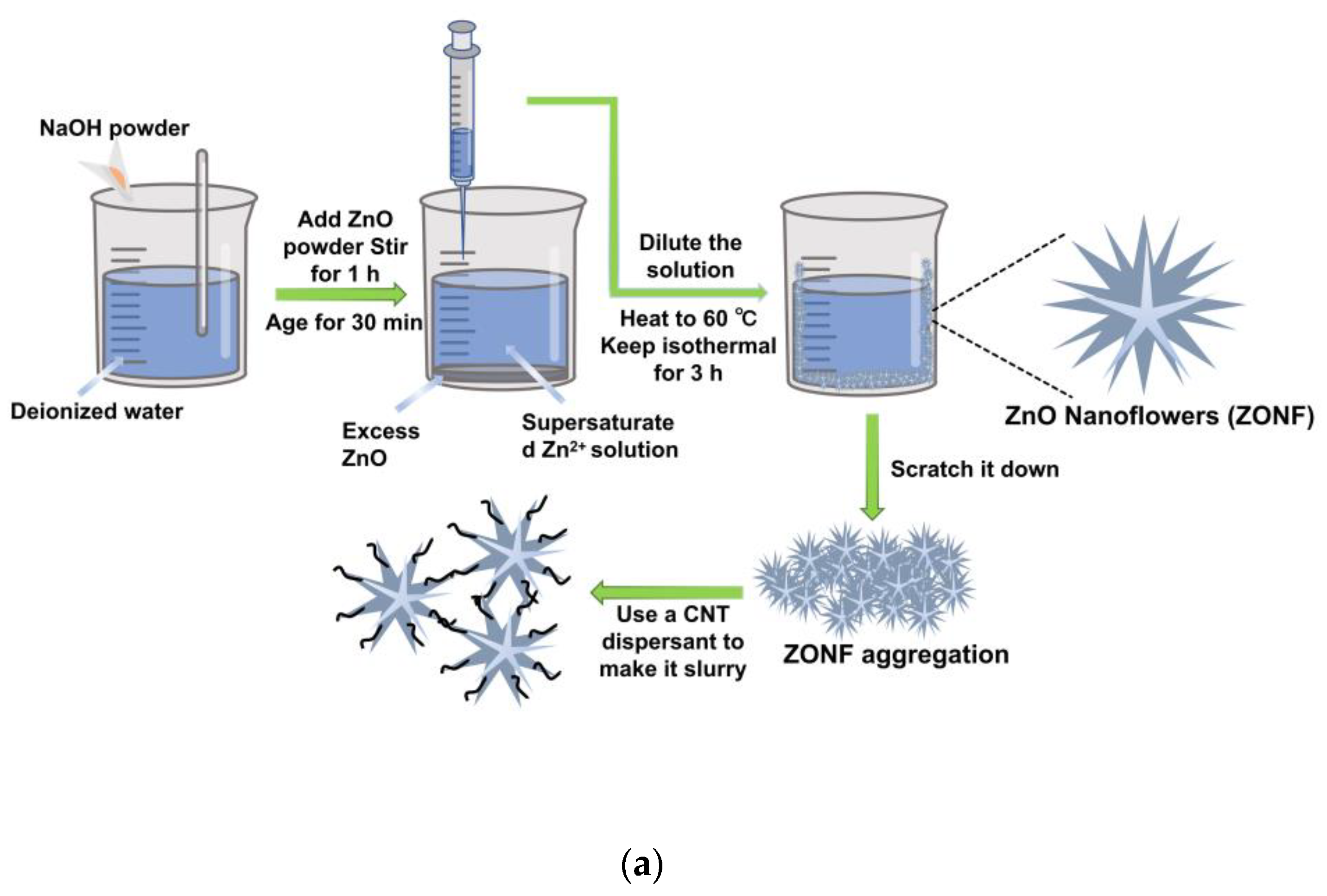
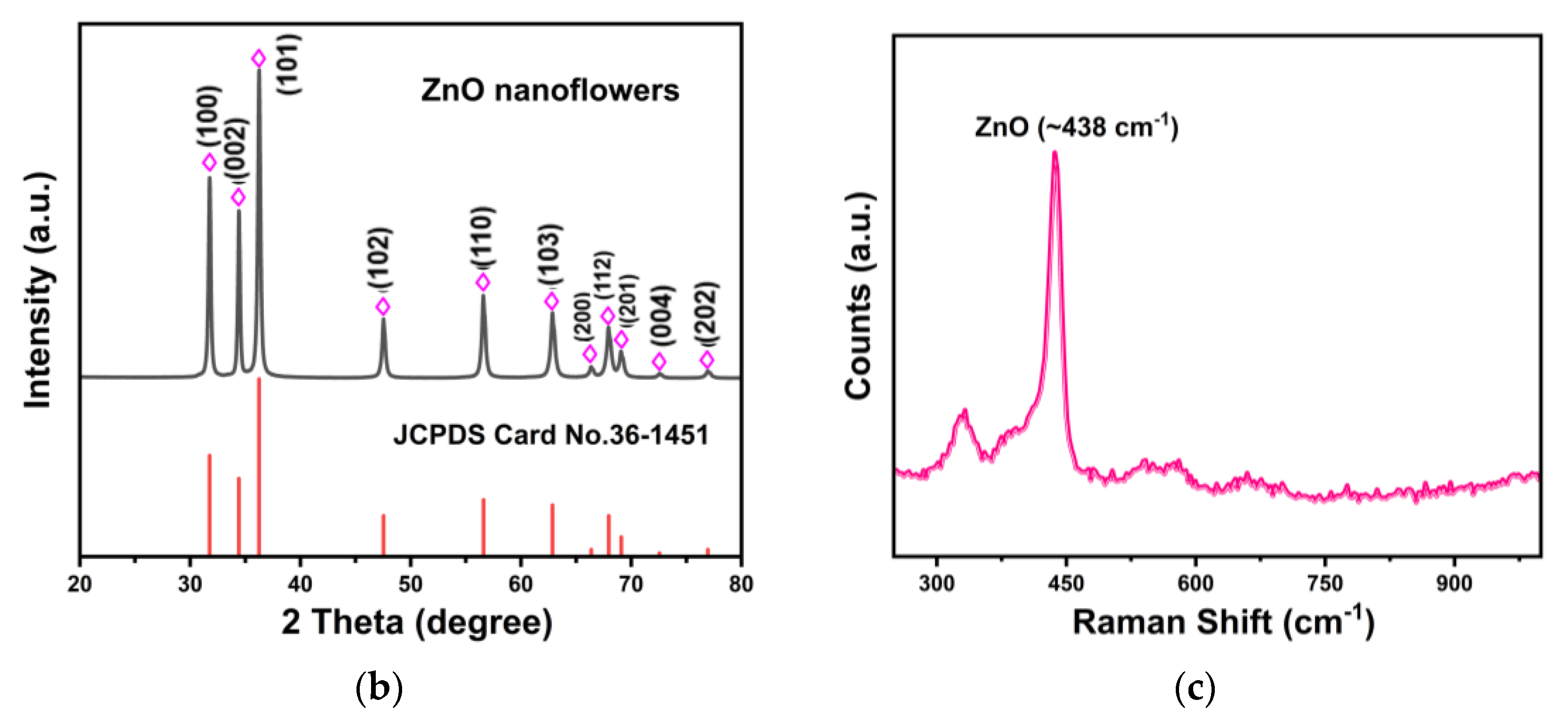
Figure 2.
(a-c) SEM micrographs of the ZONFs at low to high magnification, respectively, and (d) the histogram of the average diameter of ZONFs based on (a). (e-g) SEM elemental mapping images of the ZONFs, and (h) a typical EDS spectrum of the ZONFs. TEM images of the ZONFs at (i) low magnification and (j) high magnification, showing the structure of a whole flower and its spines, respectively. (k) HRTEM image and (l) SAED pattern acquired at the tip of a spine.
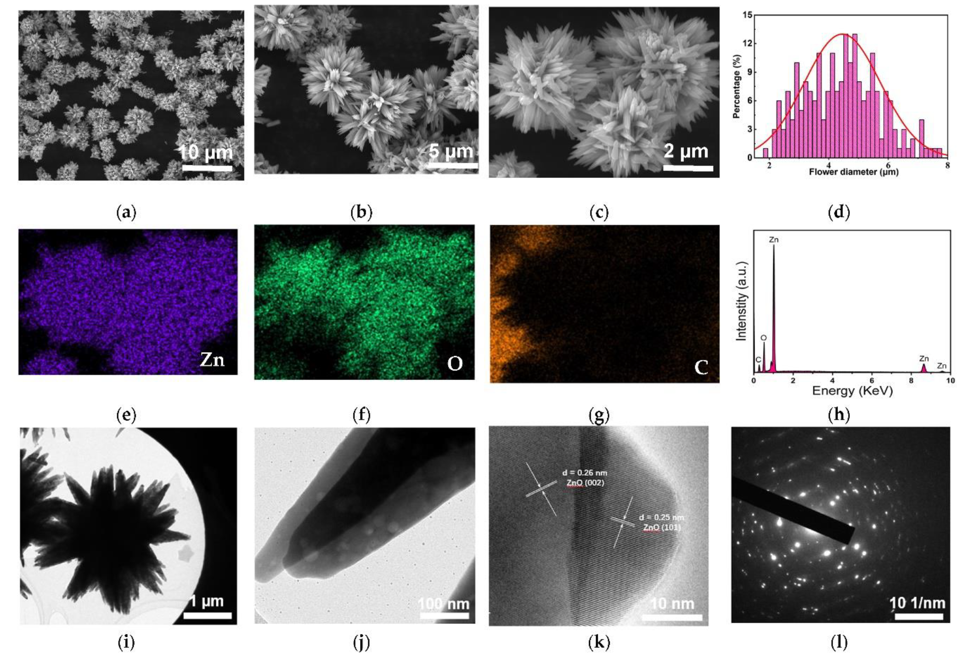
Figure 3.
(a) CV profiles of the ZONF-CNT anode at scan rates of 0.2 mV s-1. The first three charge-discharge curves of the cells with (b) the ZONF-CNT anode and (c) the conventional ZnO anode, respectively, at 0.5 C (1C = 978 mAh g-1). (d) EIS profiles of the ZONF-CNT anode and the conventional ZnO anode after 15 cycles. (e) Cycling performance and coulombic efficiency over 50 cycles for the ZONF-CNT anode and the conventional ZnO anode at a current density of 0.5C.
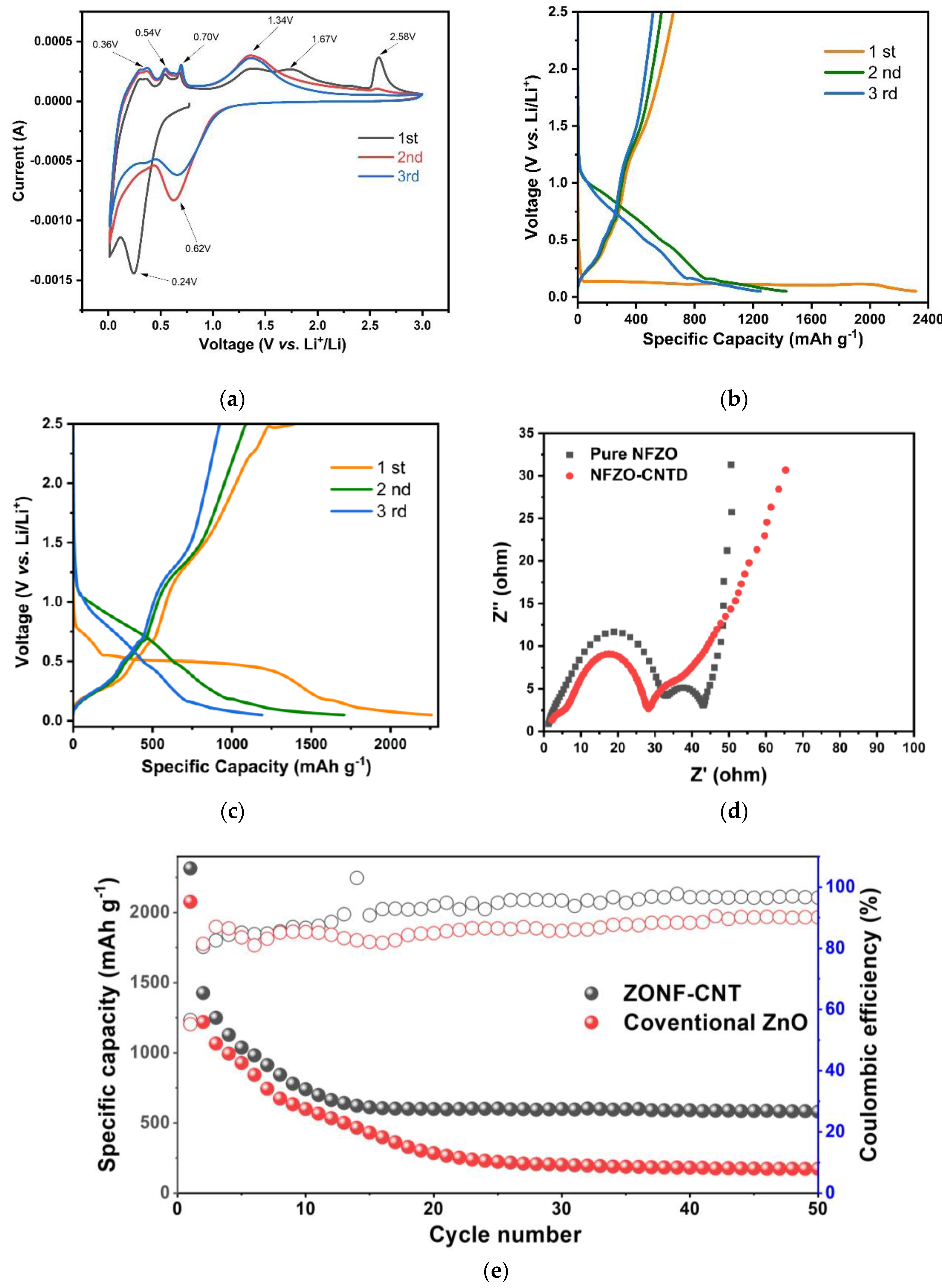
Figure 4.
(a) Cyclic voltammogram of the cells (after 5 cycles) with the ZONF-CNT anode at different rates of 1, 0.5, 0.2, 0.1, 0.05 and 0.02 mV s-1, respectively, and (b) relationship between the peak current and the square root of scanning rate; also included is the corresponding linear fittings.
Figure 4.
(a) Cyclic voltammogram of the cells (after 5 cycles) with the ZONF-CNT anode at different rates of 1, 0.5, 0.2, 0.1, 0.05 and 0.02 mV s-1, respectively, and (b) relationship between the peak current and the square root of scanning rate; also included is the corresponding linear fittings.
Disclaimer/Publisher’s Note: The statements, opinions and data contained in all publications are solely those of the individual author(s) and contributor(s) and not of MDPI and/or the editor(s). MDPI and/or the editor(s) disclaim responsibility for any injury to people or property resulting from any ideas, methods, instructions or products referred to in the content. |
© 2023 by the authors. Licensee MDPI, Basel, Switzerland. This article is an open access article distributed under the terms and conditions of the Creative Commons Attribution (CC BY) license (http://creativecommons.org/licenses/by/4.0/).
Copyright: This open access article is published under a Creative Commons CC BY 4.0 license, which permit the free download, distribution, and reuse, provided that the author and preprint are cited in any reuse.


