Submitted:
07 October 2023
Posted:
08 October 2023
You are already at the latest version
Abstract
This research endeavors to illuminate the path toward efficient and optimized propeller design by delving into the realm of aerodynamics. Propellers, as vital mechanical marvels, constitute the core of numerous propulsion systems, spanning from aircraft and marine vessels to wind turbines. The pursuit of enhanced propeller efficiency and performance holds paramount importance in industries where propulsion assumes a critical role, underscoring the indispensable need for a profound understanding of aerodynamics. Through meticulously crafted theoretical insights and their practical applications, this study embarks on a journey into the fascinating realm of propeller aerodynamics. While the paper primarily addresses the aerodynamic aspects of propeller design and optimization, it serves as a foundational guide for those seeking to comprehend the intricacies of propeller engineering.The research journey commences with an in-depth exploration of the fundamental principles governing propeller performance. It unveils the intricate dynamics of airflow surrounding propeller blades, shedding light on their proficiency in generating thrust, lift, and torque. The bedrock of the theoretical insights is a comprehensive analysis encompassing airfoil profiles, blade geometry, and the underlying principles of blade element theory. In navigating the ensuing pages, the study embarks on the task of demystifying the intricate methods and calculations that propel the design and optimization of propellers. Leveraging cutting-edge methodologies, the research systematically assesses the aerodynamic characteristics of propellers across various operational conditions. These invaluable insights empower the tailoring of propeller designs with precision, aligning them seamlessly with specific performance objectives. The aim is not only to impart a comprehensive understanding of propeller aerodynamics but also to provide actionable insights for engineers and researchers striving to enhance propeller efficiency. This research endeavor serves as a guiding light for both propeller enthusiasts and professionals alike. It not only enriches the broader discourse on propeller technology but also equips readers with the requisite knowledge and tools to embark on their own quests for optimized propeller design. As propulsion technologies continue their evolution, the steadfast principles elucidated herein will persist, guiding future innovations and advancements in the realm of propeller engineering. This paper serves as a profound resource, offering new researchers a comprehensive understanding of propellers and their intricate design processes.
Keywords:
propeller design
; aerodynamics
; propulsion
; performance
; airflow dynamics
; thrust
; lift
; torque
; airfoil
; geometry
; blade element theory
; optimization
; operational conditions
1. INTRODUCTION
The world of modern transportation and energy generation is powered by the ceaseless motion of propellers—remarkable rotating blades that quietly and efficiently propel us forward. Whether it's the swift ascent of a passenger aircraft, the graceful glide of a sailboat, or the graceful rotation of wind turbine blades harnessing the breeze, propellers are the unsung heroes of our dynamic world. In today's fast-paced technological era, the significance of aerodynamic design and optimization for these propellers cannot be overstated.
Propellers are instrumental in achieving a delicate balance between efficiency, sustainability, and safety in various industries. They are the essential components that cut through air and water, converting energy into motion while minimizing resistance and maximizing thrust. The quest for innovation in propeller design and optimization has gained momentum in response to the pressing challenges of our time. These challenges include the urgent need to reduce greenhouse gas emissions in aviation, the imperative for cleaner and more efficient maritime transportation, and the optimization of energy generation in wind farms. Propellers are at the forefront of addressing these challenges, and their efficient design and optimization are central to the solutions.
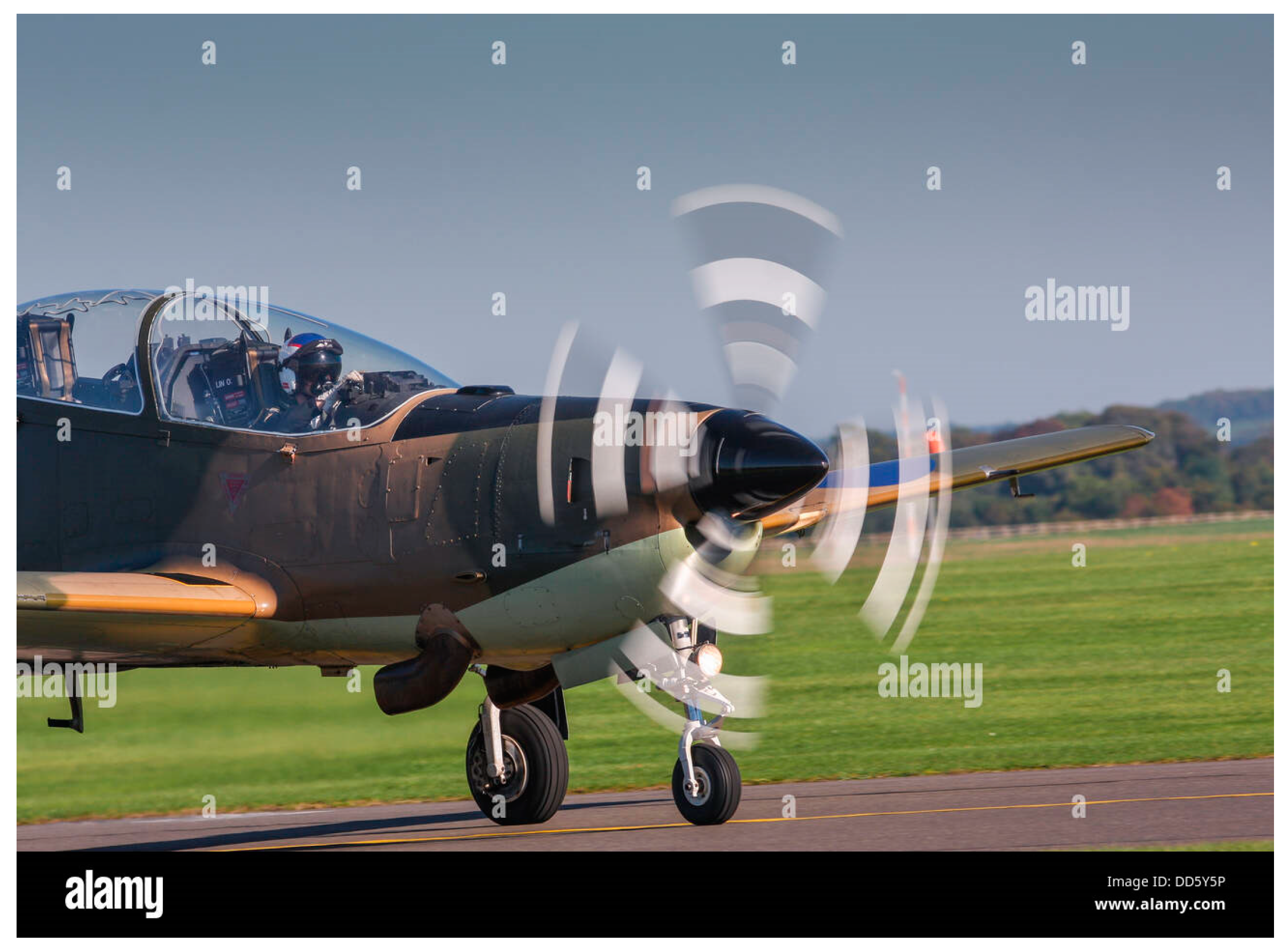
Figure 1.1.
Aircraft with propellers (Alamy, n.d.).
While propellers have been an integral part of transportation for well over a century, they are far from remaining static technology. Although propellers have a long history, the present era is marked by advancements in materials, computational capabilities, and aerodynamic insights. These advancements are driving a transformation in propeller technology, enabling them to evolve and meet the growing demands of industries striving for improved performance, reduced environmental impact, and enhanced safety. The process of propeller design and optimization encompasses numerous intricacies, from understanding fluid dynamics to optimizing blade shapes and profiles. Yet, despite its complexity, the field of propeller aerodynamics remains accessible and ripe for exploration. Understanding the entire propeller design process will provide readers with comprehensive knowledge of propeller optimization and design.
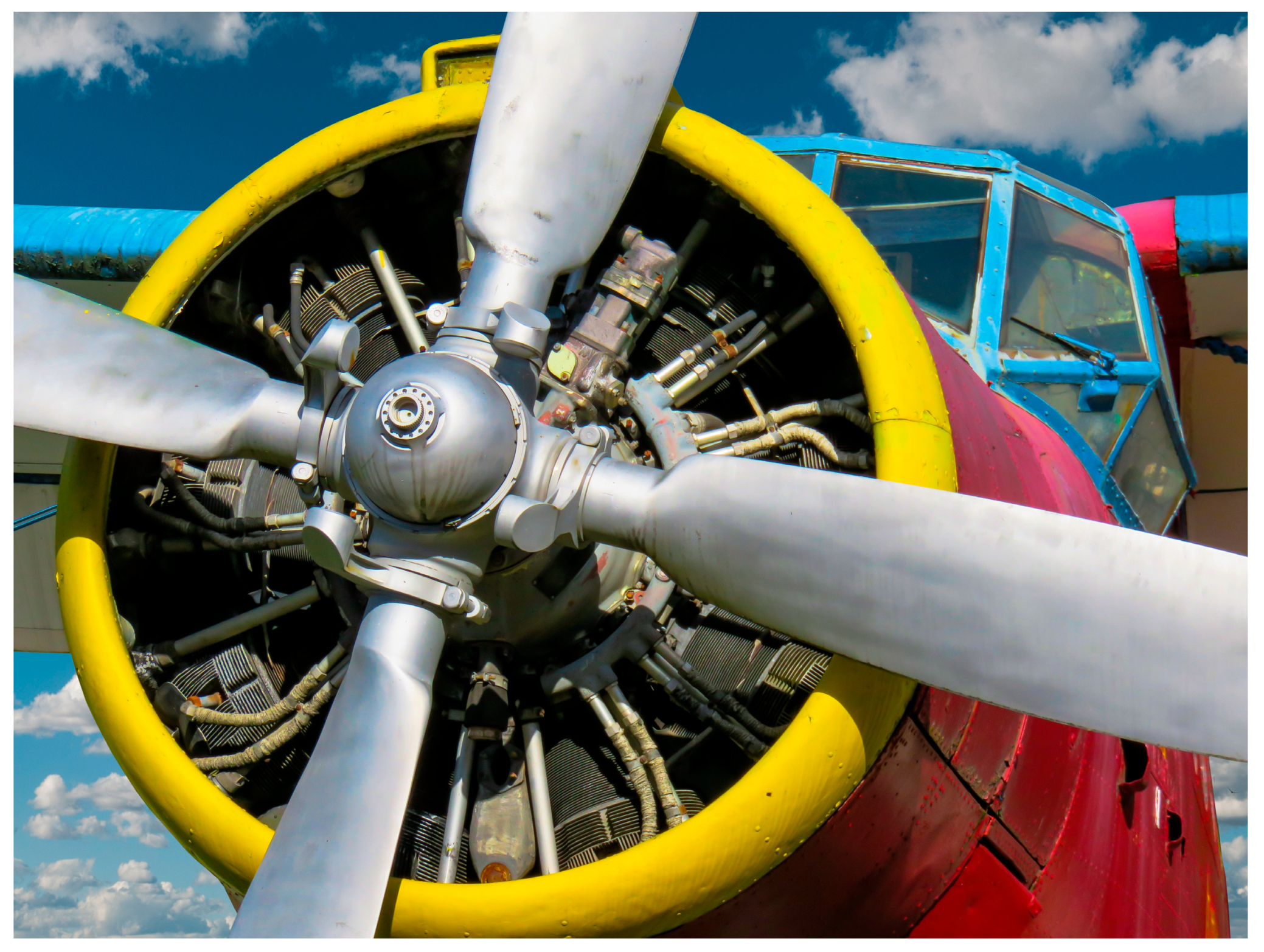
Figure 1.2.
Propellers attached to aircraft engines.(Pixabay, n.d.).
This paper embarks on a journey into the heart of propeller design and optimization with a primary focus on the intricacies of aerodynamics. We aim to unravel the intricate process of designing and optimizing propellers to meet the diverse requirements of their applications. This journey will take us through the essential theories, computational tools, and practical methodologies that drive propeller innovation. In the pages that follow, we will navigate the fascinating realm of propeller aerodynamics, demystifying the principles, methods, and calculations that drive the design and optimization of these vital mechanical marvels.
2. METHODOLOGY.
The role of the propeller is to transfer the rotational energy granted at the engine crankshaft into forwarding thrust and is used to propel the vehicle to which it is attached. Propellers are very efficient in generating thrust through a mass of air acceleration. Many aspects of the propeller design process are drawn from 'General Aviation Aircraft Design Textbook' by (Snorri Gudmundsson, 2014). However, this paper aims to provide a comprehensive explanation of propeller optimization and the aerodynamic design process. The goal is to equip readers with the knowledge needed to select a propeller that aligns with specific requirements.
The following process was taken in the design and optimization of the propeller.
- Stating the engine parameters
- Calculating the required diameter
- Propeller type
- Choosing an airfoil
- Aerodynamic Design
- Optimization
- Design on Qblade software.
- Induced velocity calculation
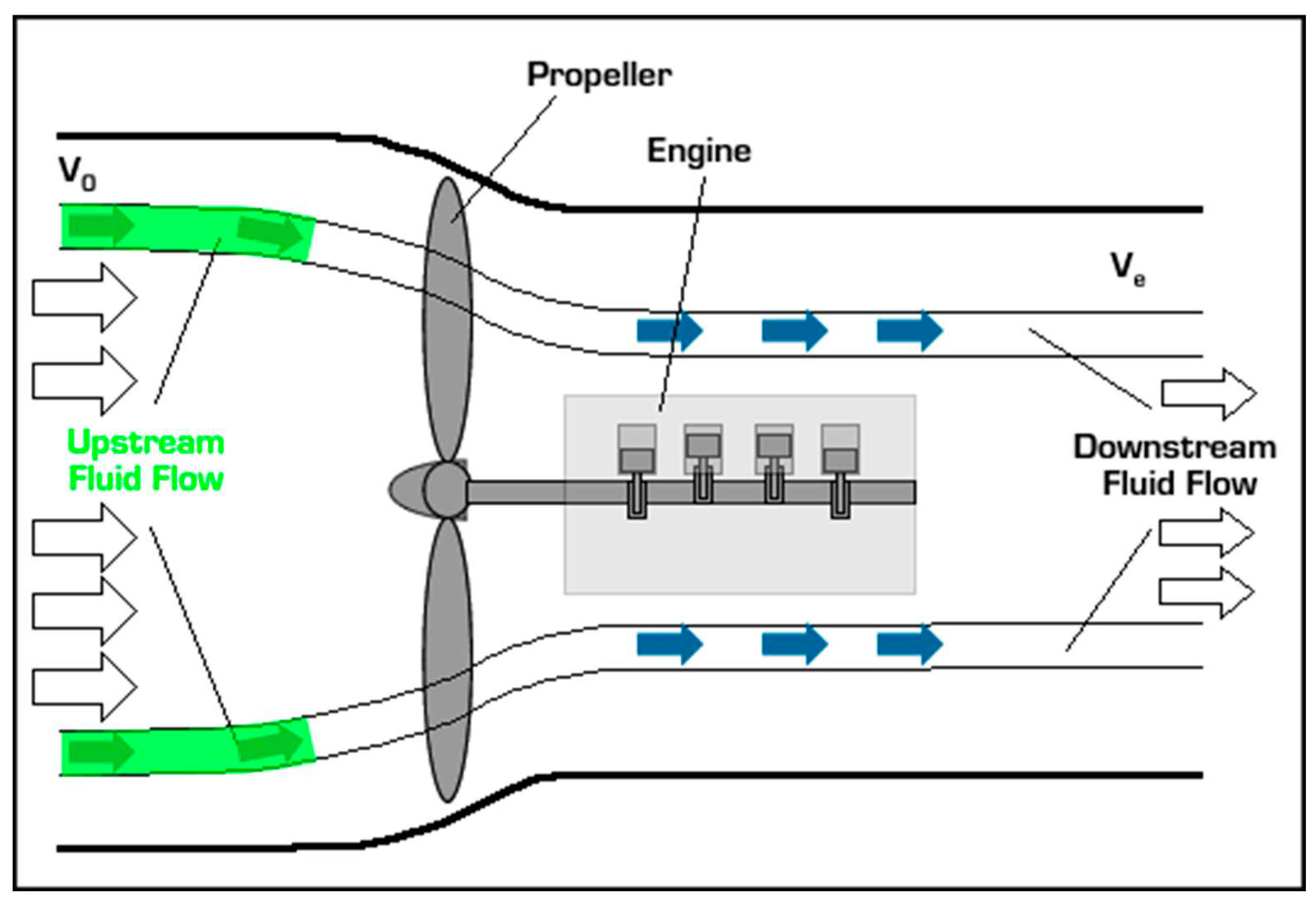
Figure 2.1.
Working principle of propeller in generating propulsive forces. (Smu.edu, n.d.).
STATING THE ENGINE PARAMETERS
The initial and crucial step in propeller design involves tailoring the propellers to match specific engine specifications. These specifications are primarily determined by three key factors: the engine's rotational speed (measured in RPM, revolutions per minute), its maximum power output capacity, and the torque it generates. Including and accurately stating these engine parameters is an integral aspect of both propeller design and optimization. By specifying the engine parameters, designers ensure not only compatibility but also overall efficiency, safety, and performance in the propulsion system. This approach not only enhances the effectiveness and durability of the propulsion system but also guarantees that it aligns with the precise requirements of the intended application. Below show the reasons for stating engine parameters
- -
- Compatibility: Engine parameters, such as power output, torque, and rotational speed, define the capabilities and limitations of the engine. To maximize propeller efficiency and performance, the propeller design must be compatible with these engine specifications. Mismatched parameters can lead to suboptimal performance and potential damage to both the engine and the propeller.
- -
- Thrust Requirements: Engine parameters help determine the thrust requirements for a particular application. By knowing the engine's power output and other relevant factors, designers can calculate the amount of thrust needed to achieve the desired performance, such as takeoff, cruising speed, or payload capacity.
- -
- Efficiency: Propeller efficiency is closely tied to engine parameters. A well-matched propeller can convert engine power into thrust with minimal losses, resulting in efficient propulsion. In contrast, an improperly matched propeller may waste energy and reduce overall efficiency.
- -
- Safety: Propeller design should consider safety factors, especially in aviation and marine applications. Engine parameters influence factors like blade strength, material selection, and structural integrity. Designing the propeller to operate within the specified engine parameters ensures safe and reliable operation.
- -
- Noise and Vibration: Engine parameters also affect noise and vibration levels. Properly matched propellers can help mitigate excessive noise and vibrations, contributing to a quieter and more comfortable operating environment.
- -
- Fuel Efficiency: Optimizing the propeller for engine parameters can enhance fuel efficiency. When the propeller operates efficiently within the engine's power band, it reduces fuel consumption, making it more environmentally friendly and cost-effective.
- -
- Longevity: A propeller that operates within the engine's specified parameters is less likely to experience excessive wear and tear. This can extend the lifespan of both the engine and the propeller, reducing maintenance costs and downtime.
In this paper, the engine parameters will be derived from the characteristics of the GX200 engine. The GX200 engine is widely employed for various domestic purposes. It is assumed that this engine has been optimized through the utilization of gear systems, resulting in the following parameters:
Maximum Torque of the engine = 13.431Nm
Maximum RPM = 3000rpm
Power = 6.5HP
The gear system optimizes the engine by increasing torque and simultaneously reducing RPM by 1.2.
Engine optimization involves a delicate trade-off among various parameters. Its objective is to strike a balance between reducing some parameters while increasing others to achieve optimal performance. The Gx200 engine, being a piston engine, delivers its maximal torque at a certain RPM, rather than at the maximum RPM. This is why engine optimization is crucial, as operating the engine at its maximum RPM might not provide sufficient torque to efficiently drive the propeller. Such an imbalance could lead to wear and tear or a reduction in propulsion system efficiency. In piston engines, the key principle is to reach the maximum torque without reaching the maximum RPM. As the RPM increases, there is a corresponding decrease in torque. Therefore, finding the right equilibrium between torque and RPM is utmost importance.
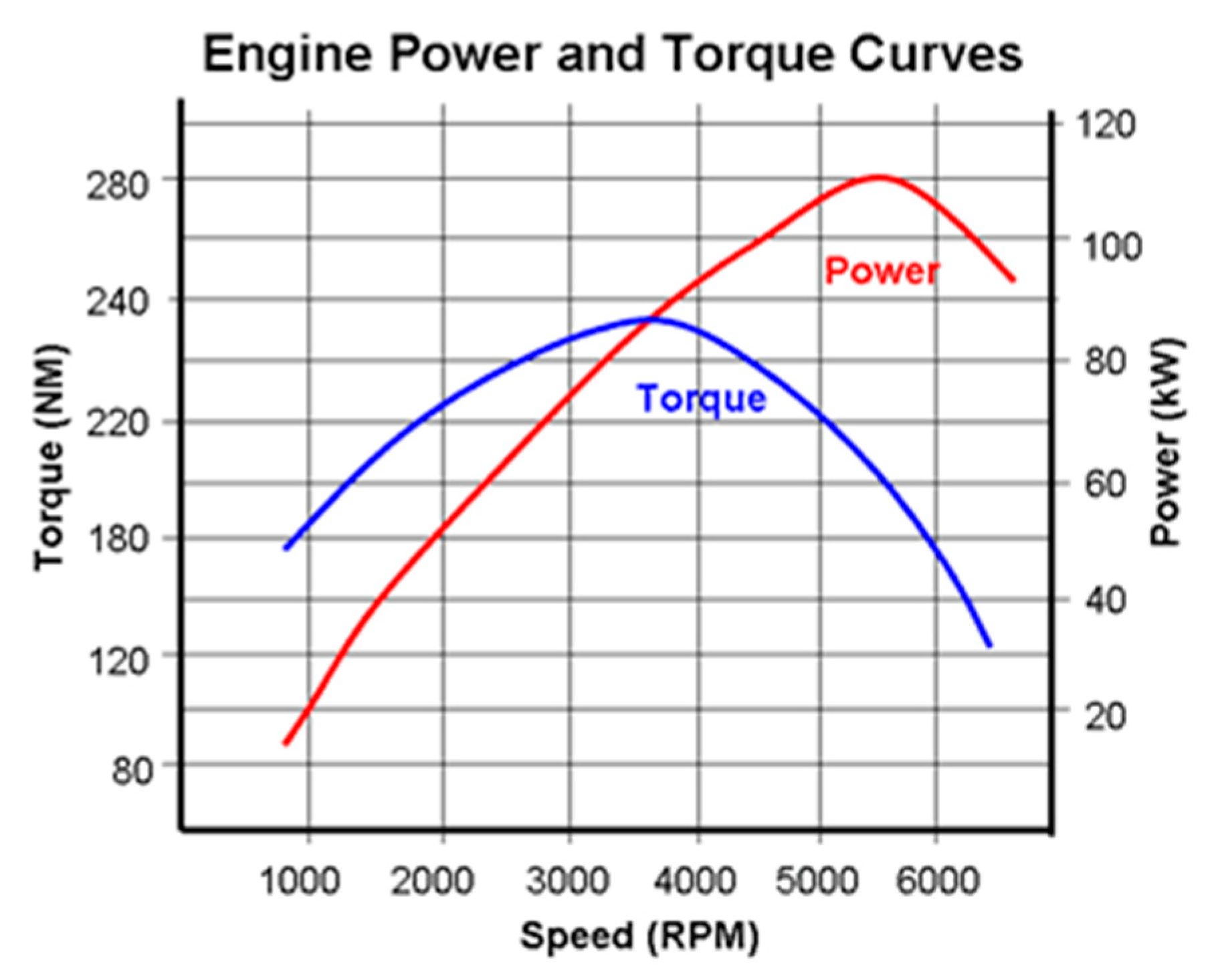
Figure 2.2.
A sample of Power, Torque and rpm relation. (Public, 2015).
CALCULATING THE REQUIRED DIAMETER
Propeller diameter refers to the distance across the circle that is traced by the tips of a propeller's blades as it rotates. In other words, it's the measurement from the tip of one blade, through the center of the propeller hub, to the tip of the opposing blade. Propeller diameter is calculated from the maximum power provided by the engine, the engine rpm, and the desired aircraft speed.
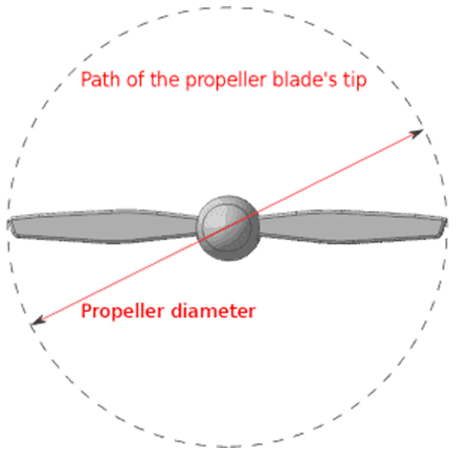
Figure 2.3.
Propeller diameter (DMS, n.d.).
It is derived from the formulae below.
Where BHP is the brake horsepower and can be calculated from engine horsepower
RPM = 3000
True airspeed = 30m/s = 58.3153knots
True airspeed is calculated in knots and represents the airspeed at which an aircraft can maintain consistent and efficient cruising flight. Essentially, it signifies the optimal speed that strikes a balance between fuel economy and travel time. This parameter is typically assumed during the design phase of a new aircraft. The assumption relies on finding aircraft with similar design attributes to the one being developed, making the selection of 'true airspeed' a relative process. The propeller diameter is determined in inches using the formula mentioned above and is later converted to the SI unit for ease of calculation. These equations provided are applicable to two-bladed propellers.
For three-bladed propellers, a different equation is employed, which involves interpolation between the equations used for two-bladed propellers.
- The provided formulas allow for various calculations depending on the number of propeller blades to be used. However, this paper will focus exclusively on the calculation for two-bladed propellers.
Two-bladed propellers are commonly used with smaller engines because of their lightweight design and higher efficiency. In contrast, three-bladed or multi-bladed propellers, while quieter and shorter, generate more power but also introduce higher drag. These are typically employed with larger engines that have sufficient torque to drive the propeller.
Speed of flying was assumed during the aircraft design calculation(Tim Kramer, 2020).
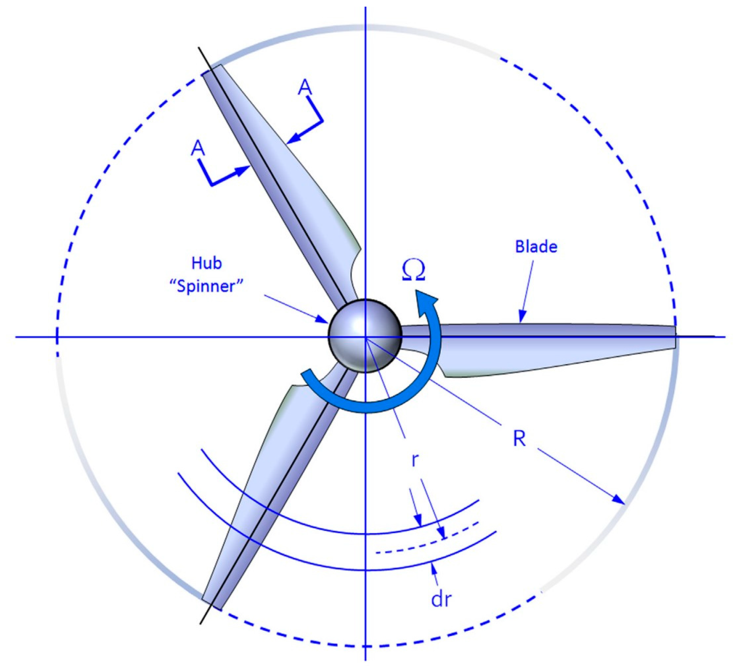
PROPELLER TYPE SELECTION
Figure 2.4.
Propeller Geometry (Snorri Gudmundsson, 2014).
- -
- Fixed-Pitch Propellers: These propellers have blades that are permanently fixed to the propeller hub at a specific pitch angle. They are simple and cost-effective but cannot be adjusted during flight.(Snorri Gudmundsson, 2014)
- -
- Variable-Pitch Propellers: Also known as controllable-pitch propellers, these can change the angle of their blades while the aircraft is in operation. This allows for optimizing performance at different speeds and altitudes.(Snorri Gudmundsson, 2014)
- -
- Constant-Speed Propellers: These are a type of variable-pitch propellers that automatically adjust their blade pitch to maintain a constant rotational speed, irrespective of flight conditions. They are often used in high-performance aircraft.(Snorri Gudmundsson, 2014)
- -
- Ground-Adjustable Propellers: These are typically used in smaller aircraft and can be manually adjusted on the ground to optimize performance for different conditions.(Snorri Gudmundsson, 2014)
- -
- Folding Propellers: Commonly used on sailplanes and some light aircraft, folding propellers can be retracted or folded to reduce drag when the engine is not in use.
- -
- Counter-Rotating Propellers: These are twin propellers mounted on the same engine, with one rotating clockwise and the other counterclockwise. They provide better efficiency and balance in multi-engine aircraft.
- -
- Ducted Fan Propellers: Often used in drones and some VTOL (Vertical Takeoff and Landing) aircraft, these propellers are enclosed within a duct or shroud for improved safety and efficiency.
- -
- Reversing propellers refer to a feature found on certain aircraft or vehicles where the propellers can change their angle of attack or direction of rotation to create reverse thrust. This capability allows the aircraft or vehicle to decelerate or even move backward on the ground or in the air by redirecting the thrust produced by the engines in the opposite direction. Reversing propellers are typically associated with controllable or constant-speed propellers. In aviation, they are commonly installed on aircraft such as turboprop airplanes. When these aircraft land, pilots can activate the reversing propellers, changing the angle of the blades to redirect airflow forward instead of backward. This generates powerful reverse thrust, aiding in the deceleration of the aircraft upon landing and providing greater control during taxiing on runways. In some cases, reversing propellers can also be used for short takeoffs and landings, as well as for maneuvering in tight spaces. The ability to reverse thrust is valuable for enhancing the safety and operational flexibility of aircraft and other vehicles using propellers for propulsion.(Snorri Gudmundsson, 2014)
In this paper, a tapered fixed propeller is utilized for the analysis, optimization, and design of propellers. This choice is motivated by the simplicity in both design and manufacturing, as well as the capacity to minimize drag and improve overall performance.
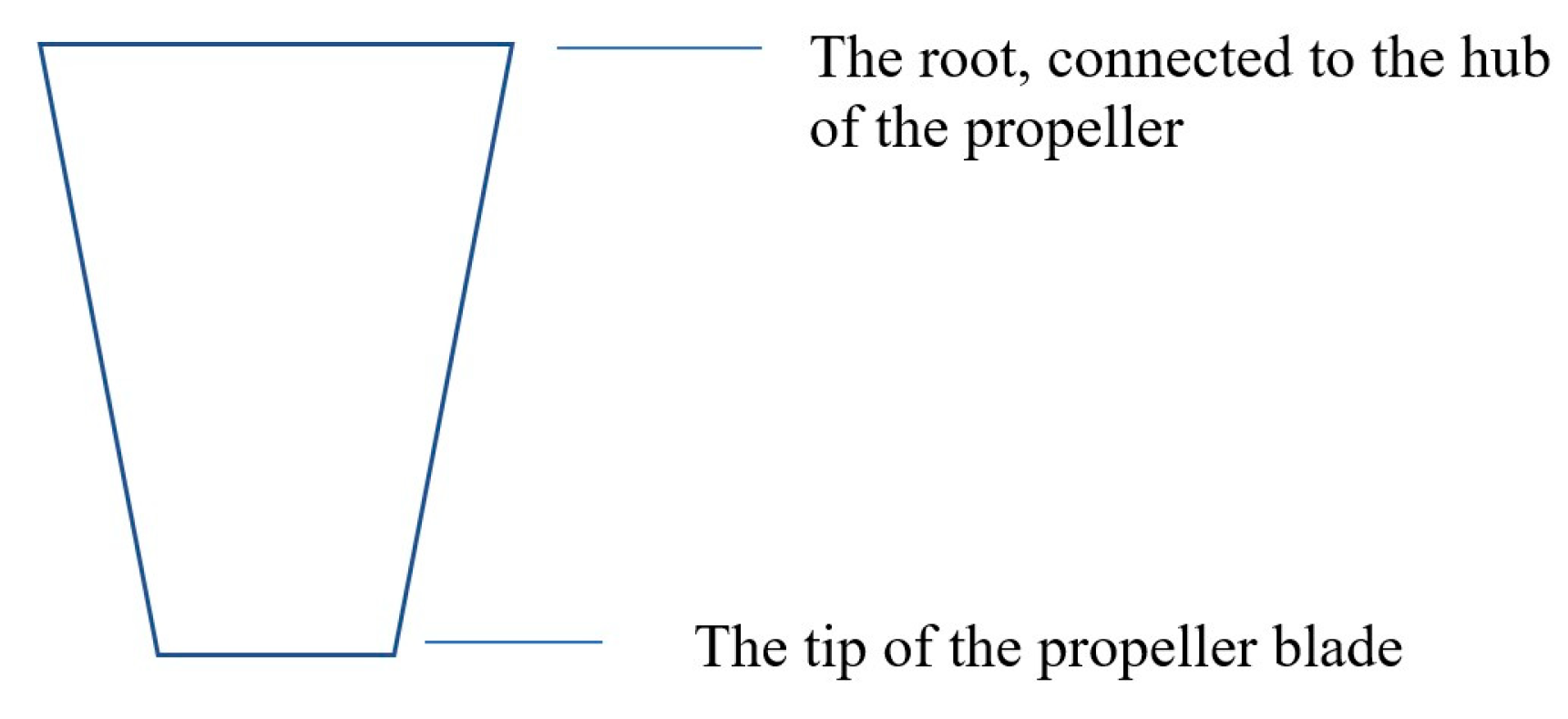
Figure 2.5.
Tapered Shape.
During my undergraduate research, I had the opportunity to observe a range of small propellers with distinct shapes in the departmental laboratory. The intriguing diversity of these shapes piqued my interest, prompting me to investigate their potential significance in propeller design. To gain deeper insights into this matter, I sought guidance from a knowledgeable senior student named Israel, who offered a valuable explanation of how propeller shape correlates with their functionality. Israel drew an analogy between propellers and wings, underscoring the pivotal role of shape in shaping their performance. He proceeded to elucidate the significance of various propeller shapes as follows:
- -
- Tapered: Tapered propeller blades exhibit a narrowing or tapering shape from the blade root (closest to the hub) to the blade tip (farthest from the hub). This design is renowned for its ability to reduce drag and enhance performance, particularly at higher speeds.
- -
- Rectangular: Propeller blades with a rectangular planform maintain a consistent width from root to tip, resulting in a straight leading edge. This design, characterized by its simplicity, is known to offer commendable overall performance.
- -
- Swept Back: Swept-back blades feature a backward angle towards the root of the blade. This configuration effectively minimizes drag and optimizes efficiency, rendering it well-suited for applications requiring high-speed performance.
- -
- Swept Forward: In contrast, swept-forward blades adopt a forward angle towards the root of the blade. This shape is also geared towards drag reduction and may find specialized applications where its advantages are pronounced.
- -
- Oval: Oval-shaped blades exhibit a rounded and elliptical planform. This configuration aims to strike a balance between performance and efficiency, making it versatile in various contexts.
- -
- Round: Blades with a round cross-sectional shape are less common and typically reserved for specialized applications.
The knowledge imparted by Israel shed light on the significance of propeller shape in achieving specific performance characteristics. While my undergraduate research did not directly delve into propeller shape, this insight ignited my curiosity and prompted further exploration into this fascinating field in the future. In the process of propeller selection, fixed-pitch propellers can be categorized into two primary types: climbing propellers and cruising propellers. Climbing propellers are meticulously designed to optimize aircraft performance, considering factors such as altitude and expected speed. Typically, these propellers are tailored for operations at sea-level altitudes.
Conversely, cruising propellers are specifically designed to enhance aircraft performance during cruising at higher altitudes. In this paper, the primary focus centers on the design of a propeller optimized for climbing characteristics, intending its operation at sea level with a speed of 30 m/s. While the primary emphasis remains on climbing propellers, relevant calculations for cruising propellers, up to a certain threshold, are provided, assuming a speed of 30 m/s and an altitude of 1000 ft. This additional information aims to offer valuable guidance to those tasked with designing propellers for cruising conditions.
It's essential to note that fixed-pitch propellers have their blade angles permanently fixed to the hub and cannot be adjusted unless a new propeller is custom-designed for a specific purpose.
Altitude was calculated for cruising propellers using the following equations.
Pressure at 1000ft (standard day)
where k is a constant value of 6.8 × 10⁻⁵
h is the altitude in ft
P is calculated in psf
Density is calculated in
is the reference density (sea level)
All values are converted into SI unit.
CHOOSING AN AIRFOIL
Airfoils
An airfoil, also referred to as an aerofoil, is a streamlined shape specifically designed to generate lift when subjected to the relative motion of air or another fluid. Airfoils are fundamental components of aircraft wings and various aerodynamic surfaces, characterized by their curved profile. They create differential air pressure between their upper and lower surfaces when exposed to airflow, resulting in an upward force known as lift. Airfoils play a crucial role in aviation and aerospace engineering, as their design and characteristics significantly influence an aircraft's aerodynamic performance, stability, and control.
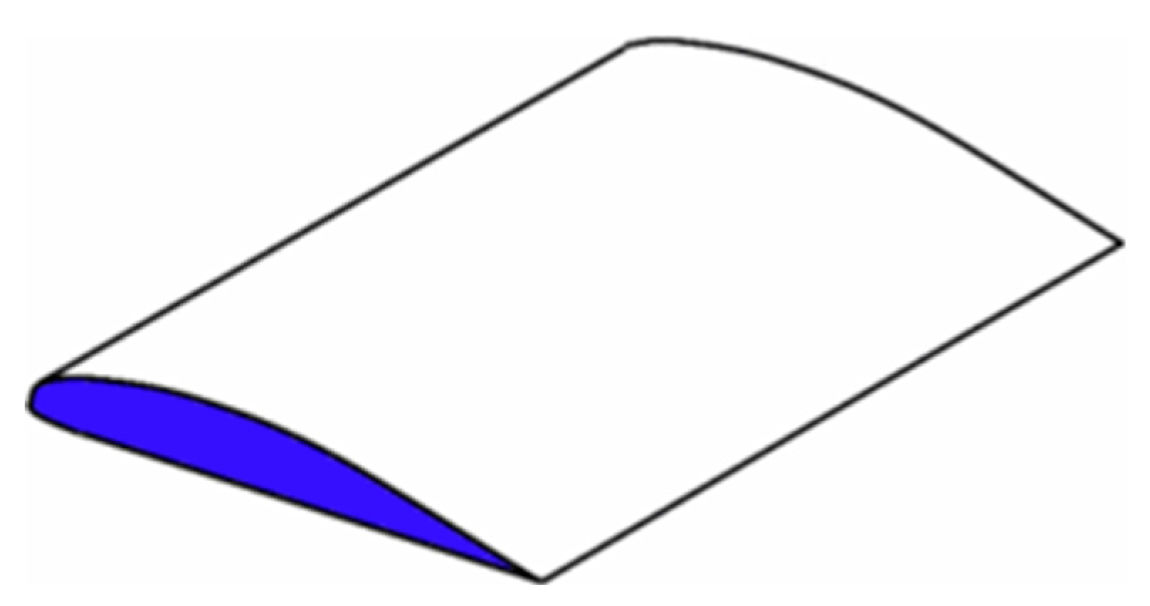
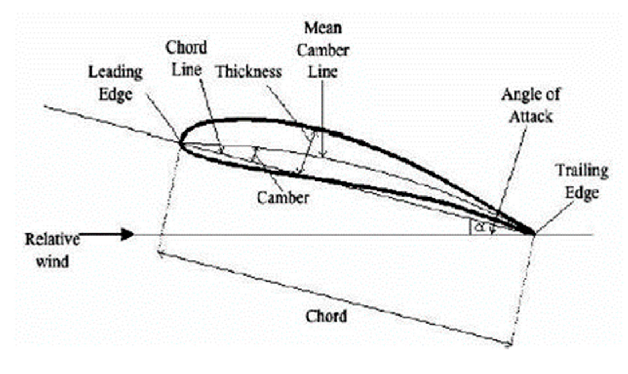
Figure 2.6.
Airfoil Wing(Class, n.d.).
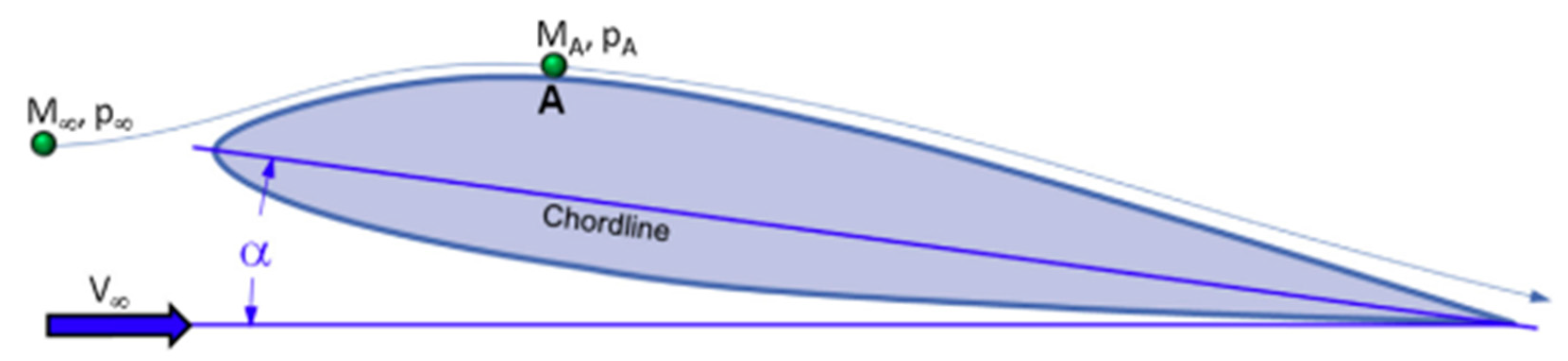
Figure 2.7.
Airfoil Geometry.(Kevadiya, n.d.).
The discovery of the airfoil has paved the way for innovative solutions in sustainable aviation. Airfoils are known for their efficient means of generating lift, but they continue to be designed for increased efficiency. Designers have developed thousands of different airfoil shapes for various applications, serving different aircraft and propellers. Some designers introduce new airfoil shapes into their designs, while others adapt existing ones. Additionally, some designers modify existing airfoils as a starting point to achieve desirable attributes. Such modifications often involve adjustments to the airfoil's geometry, such as thickness and camber, or optimization between two different airfoils by utilizing the attributes of one to compensate for the other. Typically, this process involves a trial-and-error approach until the desired characteristics are achieved.
According to(Snorri Gudmundsson, 2014) book, specifically in the chapter titled 'Anatomy of an Airfoil,' there are certain concepts that designers should consider when designing an airfoil. These concepts are listed below:
- Lift coefficient and Drag coefficient: The primary function of an airfoil is to generate lift efficiently while minimizing drag. Look for airfoils that provide the desired lift-to-drag ratio (L/D ratio) for your application. Higher L/D ratios indicate better lift generation with less drag.Figure 2.8. Airfoil in A Flow (Dr. SNORRI, 2014, page 281 ).
- 2.
- Thickness, Mean-line and Camber: The camber is defined as the maximum distance between the mean-line and the chord line. Camber strongly affects the downwash behind the airfoil and, thus, how much lift is generated. The rule-of-thumb is that the larger the camber, the greater the maximum lift of the airfoil and greater the thickness the greater the stall angle-of-attack and drag. Generally, the greater the camber the greater is the drag as well. Airfoils with camber may provide additional lift compared to symmetric airfoils. Thin airfoils tend to have lower drag but may be less structurally robust (Snorri Gudmundsson, 2014).
- 3.
- Leading edge radius: The leading-edge radius of an airfoil refers to the curvature or smoothness of its front edge. It impacts the airfoil's aerodynamic performance, including lift and drag characteristics. Smoother leading edges reduce drag but may generate slightly less lift, while sharper leading edges may lead to earlier stall behavior. The choice of leading-edge radius is application-specific and can influence manufacturing and design optimization. It's a critical parameter that designers tailor to meet specific performance goals and operational conditions.(Snorri Gudmundsson, 2014)
- 4.
- Square Trailing edge: A square trailing edge of an airfoil represents a flat, perpendicular termination at the back end of the airfoil. This design element contrasts with tapered or rounded trailing edges. A square trailing edge can simplify manufacturing processes and reduce costs but may also result in higher drag compared to other trailing edge shapes. The choice of a square trailing edge can affect an airfoil's lift and drag characteristics, making it an important parameter to consider when designing for specific applications. A square trailing edge is sometimes employed to decrease adverse pressure gradients on airfoils. This is important for NLF airfoils (which feature the maximum camber way back along the chord) to help stabilize the boundary layer on the aft part of the airfoil. This way, the formation of a separation bubble is prevented and, consequently, both lift and drag characteristics are improved. It is of importance how the TE is squared. A sharp trailing edge cannot just be made blunt, as this will not increase the thickness of the airfoil upstream. Rather, the TE must be deliberately thickened to improve adverse pressure gradient(Snorri Gudmundsson, 2014). Designers may opt for a square trailing edge when simplicity and cost-efficiency are essential, but they must be mindful of the potential trade-offs in aerodynamic performance.
- 5.
- Airfoil Naming and their description: The name of an airfoil provides information about its family or series, its chord length, its maximum thickness, and, in some cases, its camber line. This naming convention helps engineers and designers quickly understand the fundamental characteristics of an airfoil simply by examining its name. Airfoil names represent groups or families of airfoils that share similar characteristics and are often developed together (Snorri Gudmundsson, 2014). Examples of airfoil groups or families include the NACA series and the Clark Y airfoil.Figure 2.9. Interpretation of NACA Four-Digit Airfoil Designation (Snorri Gudmundsson, 2014).
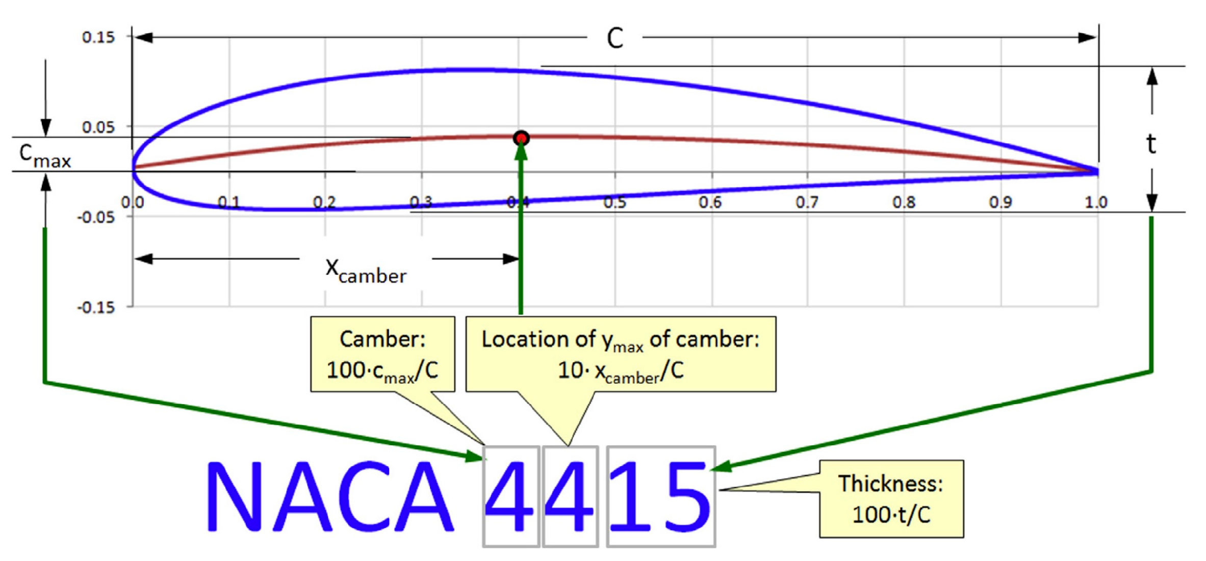
The four-digit airfoils find extensive application in general aviation (GA) aircraft, with notable usage in a range of Cessna aircraft models. Cambered airfoil variants are primarily employed for wing designs, while symmetric counterparts are preferred for horizontal tails (HT) and vertical tails (VT). Symmetric airfoils also have diverse applications, including helicopter rotor designs, antenna structures, and even on certain supersonic aircraft and missile fins.
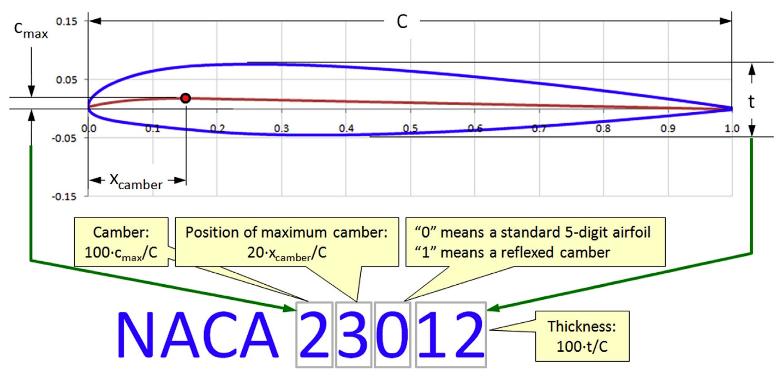
Figure 2.10.
Interpretation of NACA Five-Digit Airfoil Designation (Snorri Gudmundsson, 2014).
The NACA Five-Digit Series uses the same thickness forms as the Four-Digit Series but the mean camber line is defined differently and the naming convention is a bit more complex (Jacobs et al., 1933). The five-digit airfoils enjoy extensive utilization in general aviation (GA) aircraft, commuter planes, and business jets, primarily serving as wing components. A variety of aircraft models produced by Beechcraft, among others, employ five-digit airfoils. Several series of airfoils exist, especially the NACA airfoils. While this paper may not cover all of them in detail, the following sections discuss their respective advantages, disadvantages, and applications.
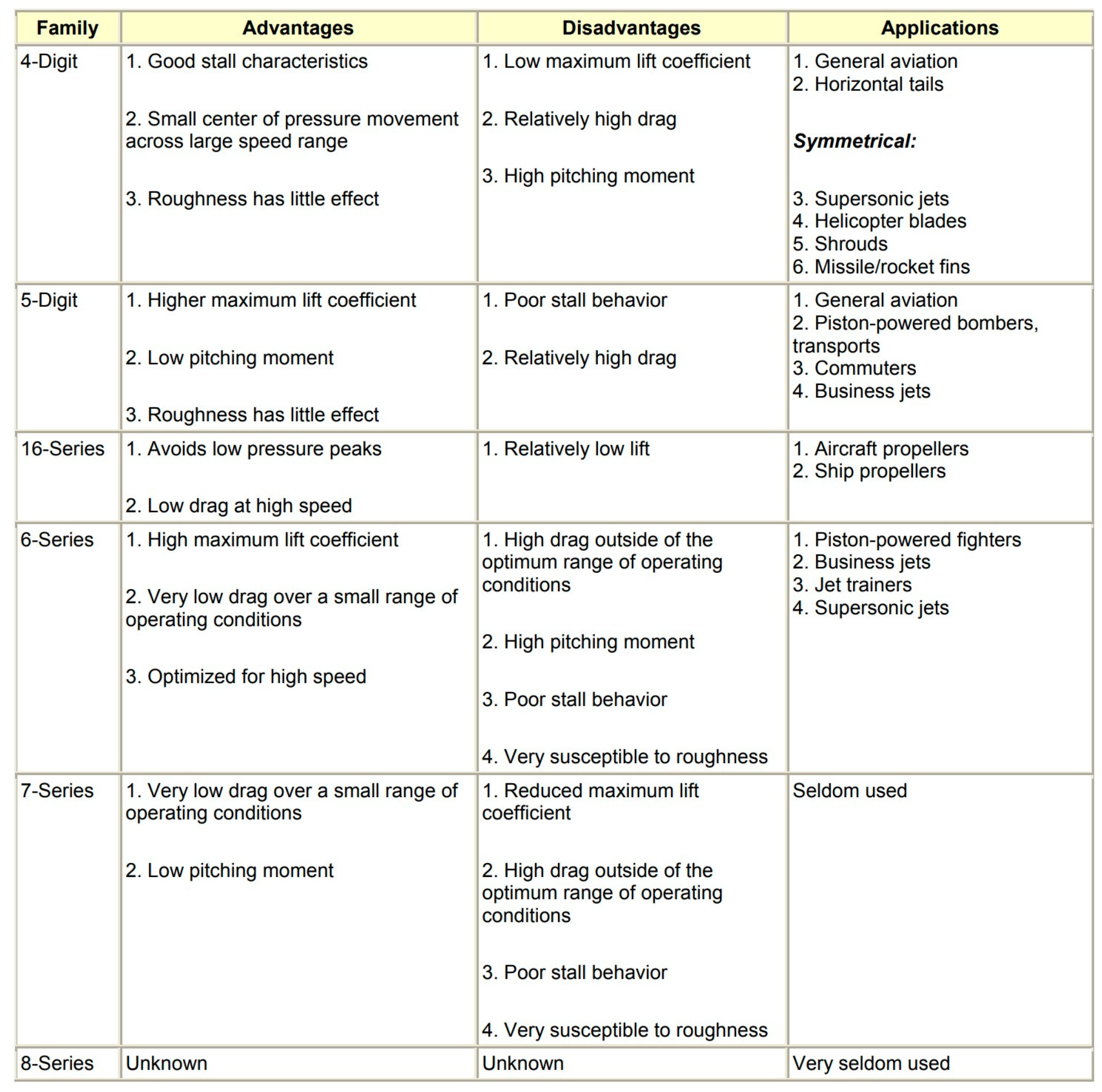
Figure 2.11.
Pros and Cons of NACA Airfoils (Jacobs et al., 1933).
These are the essential airfoil geometry terms that every designer must be familiar with.
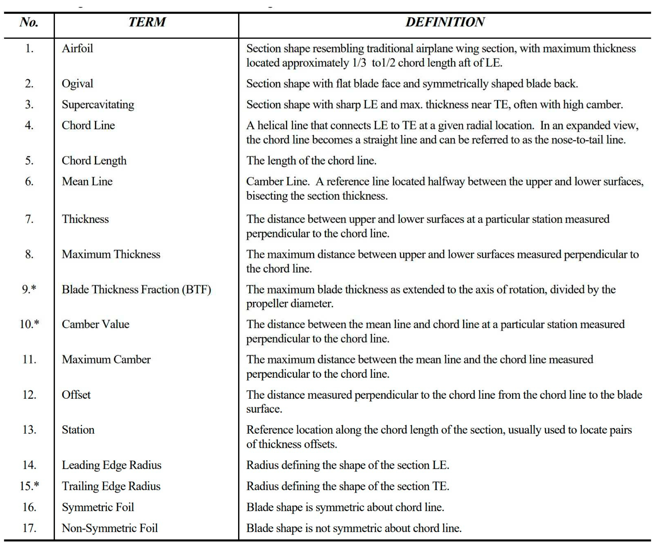
Figure 2.12.
Summarized Airfoil Geometry (Document, 2000).
This paper's primary focus is the adaptation of an existing airfoil for propeller design and optimization. The decision to adapt an existing airfoil stems from the substantial computational analysis required for the creation of a new one. While some analysis is presented within this paper, our attention centers on two specific existing airfoils. The selection of the appropriate airfoil for the propeller is contingent on various design parameters and specifications. These considerations encompass the aircraft's performance range, engine parameters, and the desired speed of operation. In the context of the GX200 engine used for aircraft propulsion in this paper, its relatively lower torque output restricts its ability to effectively swing larger propellers. As a result, the GX200 engine is most suitable for subsonic flight applications. Accordingly, the design parameters herein are tailored to accommodate subsonic flight characteristics. To illustrate the significance of torque, envision an engine capable of producing three to four times the torque of the GX200 engine. Such an engine would possess the capacity to rotate significantly larger propellers, thereby generating three to four times the propulsive force. In the realm of subsonic flight, the objective is the selection of an airfoil that can generate substantial lift with minimal drag. For this study, we have chosen to work with the Clark Y and E63 airfoils.
The Clark Y airfoil boasts a thickness of 11.7% and a straight bottom surface after the 30% chord point. This design feature contributes to its commendable efficiency in terms of lift-to-drag ratio. Conversely, the E63 airfoil possesses a thickness of 4.27% and a non-straight bottom surface, with trailing edges curving closer to the leading edge. This unique design imparts greater efficiency in lift generation while concurrently minimizing drag.
2.1. The Selection of Airfoils: Reasons for Choice and Consideration
The clark Y airfoils: The Clark Y airfoil holds a prominent place in aviation history as one of the most extensively used profiles, especially in aircraft designed prior to World War II. Its nomenclature pays homage to Colonel Virginius E. Clark (1886 - 1948), a prolific airfoil designer during the World War I era. The inception of the Clark Y airfoil dates back to 1922, and one of its distinctive characteristics is the flat lower surface, which extends from 30% chord to the trailing edge. This characteristic offers excellent stability in both lift generation and control, which are crucial parameters for aircraft across various flight conditions. Comprehensive aerodynamic data for the Clark Y airfoil can be found in a study by (Silverstein, 1935). This airfoil has graced the wings of several iconic aircraft, leaving an indelible mark in aviation history. Notable examples include Charles Lindbergh's historic transatlantic flight aboard the Ryan NYP Spirit of St. Louis in 1927, Amelia Earhart's journey across the Atlantic in the Lockheed Vega, and Wiley Post's circumnavigation of the globe aboard his beloved "Winnie Mae." The Clark Y airfoil finds mention in the University of Illinois at Urbana-Champaign (UIUC) airfoil database an impressive 493 times, attesting to its enduring legacy across 7,420 instances of various aircraft types.(Snorri Gudmundsson, 2014)
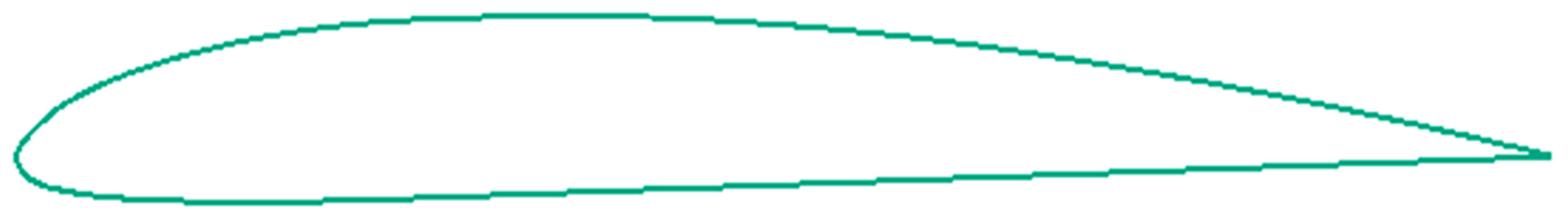
Figure 2.13.
Clark Y Airfoil.
E63 airfoil: The E63 airfoil is a low Reynolds number airfoil designed by Eppler. It has a maximum thickness of 4.3% at 22.8% chord and a maximum camber of 5.3% at 50.5% chord.. The airfoil is widely used in various applications, including small aircraft and unmanned aerial vehicles (UAVs) (bing, n.d.).

Figure 2.14.
E63 Airfoil.
AERODYNAMIC DESIGN
Propeller aerodynamic design is a complex and iterative process that demands expertise in aerodynamics, structural engineering, materials science, and computational modeling (Rizzi & Oppelstrup, 2021). This comprehensive and multidisciplinary approach takes into account various factors and considerations, including performance requirements, blade geometry, airfoil selection, blade loading distribution, and more. This paper focuses on aerodynamic design, modeling, and optimization. The propeller was designed using Blade Element Momentum Theory (BEMT), with the induced velocity part calculated using actuator disk theory. The choice of BEMT and actuator disk theory was driven by their simplicity, which enables faster iterations in the design process.
Blade Element Momentum Theory offers a detailed method for understanding aerodynamic performance. It divides the propeller blade into sections and estimates the thrust acting on each section. This theory treats each segment (element) as a two-dimensional airfoil, allowing the calculation of aerodynamic forces based on flow velocity. The resultant aerodynamic forces are aggregated to estimate the properties of each section of the propeller. These summed properties are then multiplied by the number of blades in the propeller. One of the primary advantages of Blade Element Momentum Theory lies in its capability to model the gradual transition of the airfoil's shape from thick near the hub to thinner towards the tip.
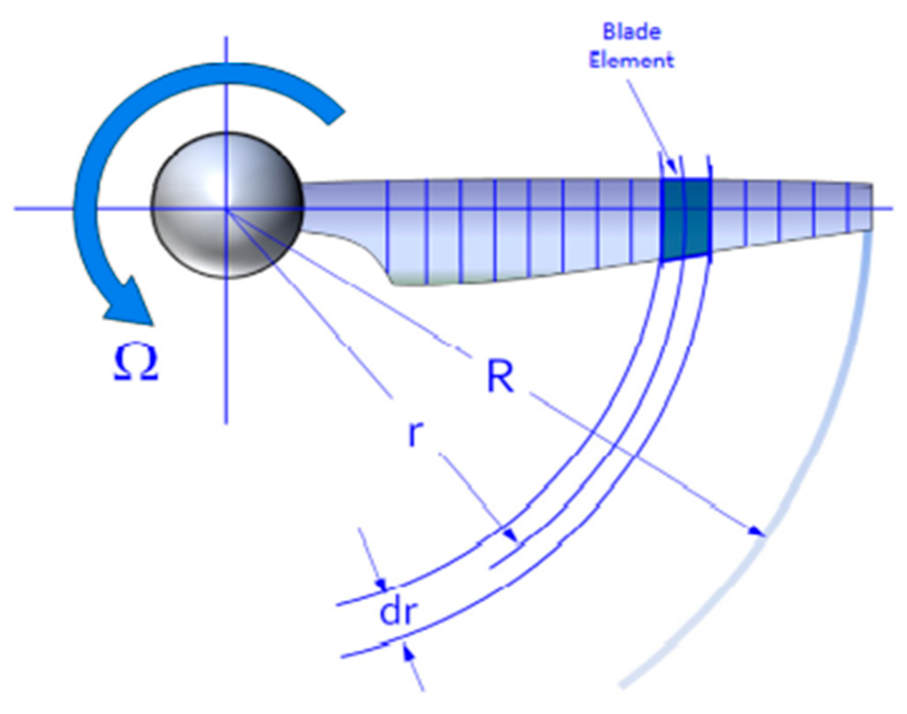
Figure 2.15.
Propeller blade sectioning using BEMT (Snorri Gudmundsson, 2014).
The calculation of blade element momentum theory was performed using Excel, considering various factors such as:
- The engine parameters: The Gx200 engine
Maximum Torque of the engine = 13.431Nm
Maximum RPM = 3000rpm
Power = 6.5HP
- 2.
- Number of propeller blade and the diameter:
No of propeller blade: 2
Diameter = 0.987298m
- 3.
- Propeller type selection: Fixed-Pitch tapered Propellers
Propeller operating condition: sea level and 1000ft.
Chosen airfoil: Clark Y and E63.
2.2. PROPELLER CALCULATION
2.5.1.1 Available Information
The excel calculation using blade element momentum theory is shown below:
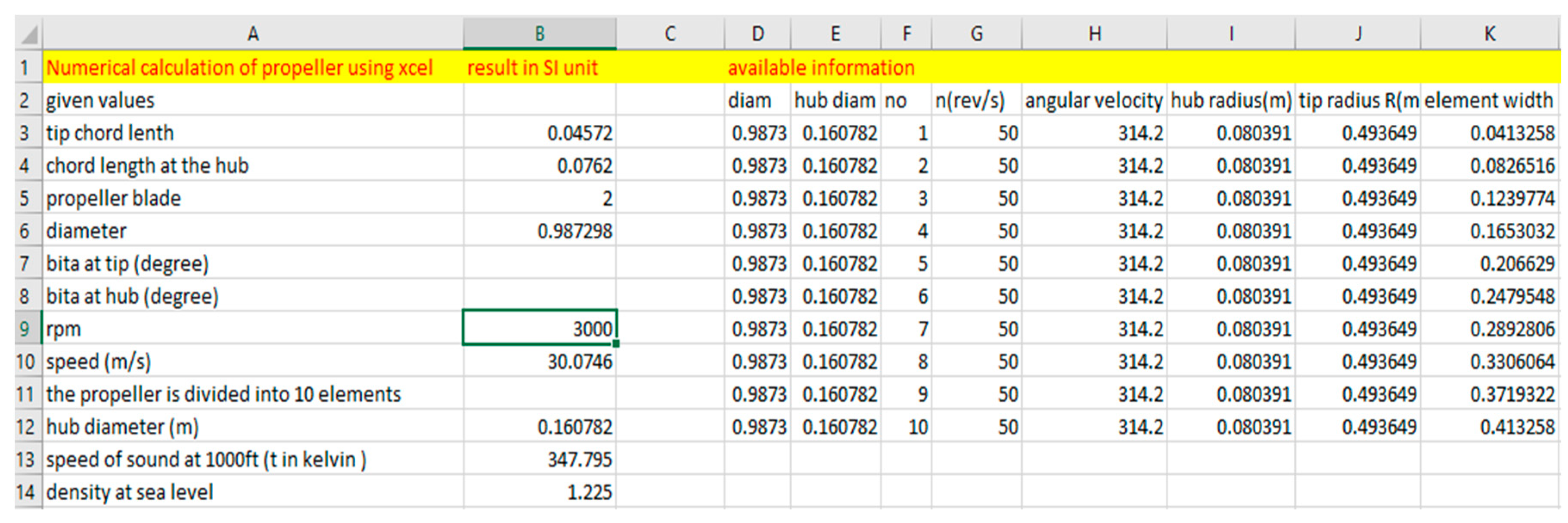
Figure 2.16.
Propeller Available Information.
What to take note:
- Hub Diameter: The diameter of the GX200 engine's shaft was measured, and a slight addition of a few meters was made to ensure a proper fit. The value used for the diameter is 0.160782. It's important to note that the propeller diameter already includes the hub, so the propeller diameter is the hub's diameter subtracted from the total propeller diameter. The selection of the hub diameter must be made with care, as it can significantly impact propeller efficiency. Opting for a smaller hub diameter can reduce hub drag, potentially improving overall efficiency. However, overly small hubs may compromise structural integrity. Hub adjustments may be necessary to address considerations such as thrust distribution, cavitation, tip effects, and aerodynamic efficiency.
Propeller diameter = Hub diameter + (propeller total diameter-hub diameter)
-
Chord Length at the Hub and Tip:** Estimating the chord length of a propeller can be a challenging task. Designers have various methods for determining this parameter. Some rely on experience, while others utilize prototyping and simulations to validate propeller performance. The chord length plays a critical role in the aerodynamic performance of the propeller, as it directly influences the propeller's overall area. Designers often adjust the chord length to achieve specific lift and drag outputs, a process considered a means of optimizing propeller performance. One common approach involves dividing the propeller diameter by 12.6 to determine the chord length at the hub and then multiplying the hub chord length by 2/3 to obtain the tip chord length. These initial values may then be further adjusted to achieve desirable characteristics. By manipulating the chord length along the blade, designers can manage lift distribution, reduce drag, and mitigate the risk of stall at the blade tips, ultimately improving overall propeller efficiency.For the optimization process in this study, a chord length of 0.0762 meters is selected for the hub, while a chord length of 0.04572 meters is chosen for the tip. These values adhere to the 12.6 rule mechanism. It's important to note that these values remain constant throughout the calculations, as no adjustments are made in this regard.
- Density: Certainly, here's the revised sentence: In this paper, density calculations are based on sea level conditions, with a particular focus on the climbing properties of the propeller. Additionally, we include calculations relevant to cruising propellers at an altitude of 1000 feet.
2.5.1.2 Parameters Calculation
The solution breaks the propeller into 10 element of equal width. The preliminaries are calculated as follows;
- Revolution (n): Propeller revolution refers to the number of complete rotations or turns that a propeller makes in a specified unit of time, typically measured in revolutions per minute (RPM). It indicates how fast the propeller is spinning. In this case it was converted to revolution per seconds using this formula. Denoted with n(rev/s)
- Angular velocity (Ω): Angular velocity is the rate at which the propeller blades rotate around their central axis. It is measured in radians per second and indicates how quickly the blades spin as they generate thrust or lift. In simpler terms, it tells how fast the propeller is turning. It is denoted with angular velocity
- Hub radius : The hub radius refers to the distance from the center of a propeller hub (the point where the blades are attached) to the outer edge of the hub. It is denoted with hub radius
- Tip radius (R): The tip radius of a propeller refers to the distance from the center of the propeller hub (where the blades attach) to the outermost point of one of its blades. In other words, it is the measurement from the center of the hub to the tip of a propeller blade. It is denoted with Tip radius
- Element width (element width): This involves dividing the propeller into small element along its along its span. The section element is 10 because the blade is sectioned into 10
2.5.1.3 Blade Geometry Calculation
Figure 2.17.
Blade Geometry.
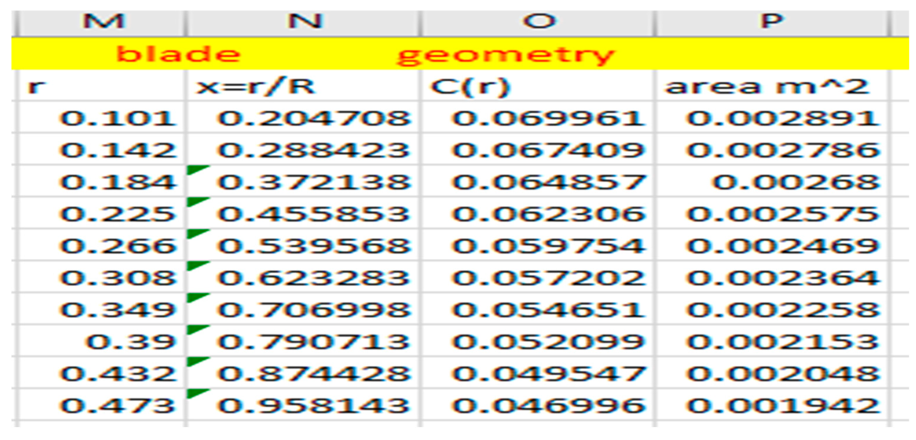
Keeping in mind that numerical subscripts refer to the row number, we get:
- 6.
- Radius (r) = propeller radius with increasement from the hub.
- 7.
- Radial roll calculation:
- 8.
- Fraction of the blade span: this is the propeller radius with increasement divided by the tip radius
- 9.
- Chord across the propeller: This deals with how the blade chord is linearly tapered across the blade span. For the propeller design, a value of 0.0762m is selected for the chord length at the hub and 0.04572m is selected for the tip which means the chord is linearly from 0.0762 at the root to 0.04572 at the tip. The parametric calculation is as follows:where A is constant, Co = Chord length at the hub and C(R) is the chord length at the tip.
Therefore,
Where
0.04572 = 0.0762 + A.R
The value of A can be substituted back in equation 1
-----final chord calculation
- 10.
- Area of the blade element: Area is the product of the chord across the propeller blade and the element widthΔA = c(r)Δr
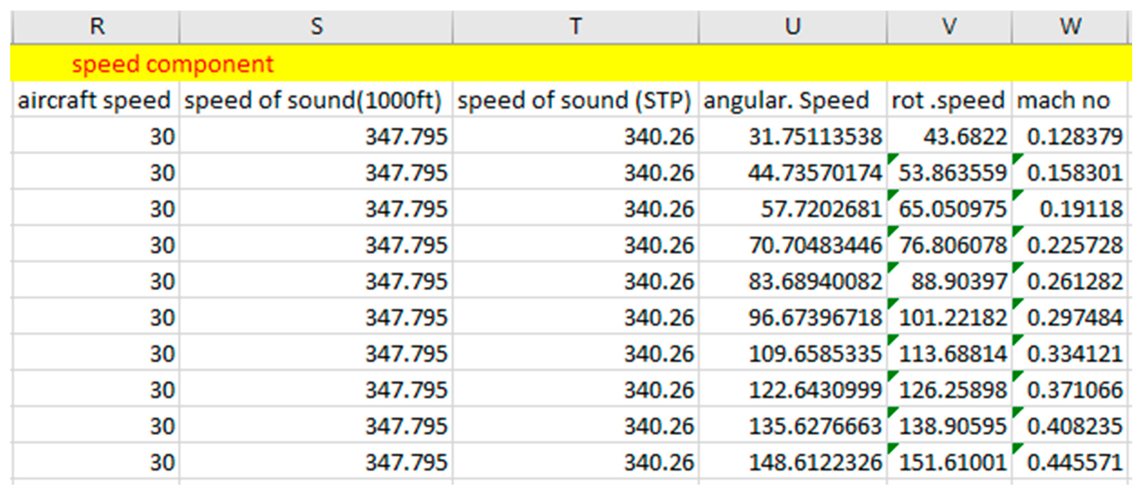
2.5.1.4 Airspeed Component
Figure 2.18.
Airspeed Component
- 11.
- Aircraft speed: this value is constant, it is the speed at which the aircraft is flying.
- 12.
- Angular speed: This is the product of (Ω.r). It quantifies how each section of the blade spin.
- 13.
- Blade rotational speed calculation: This is the rate at which each section of the propeller rotate
- 14.
- Mach number: Mach no is calculated for an altitude at 1000ft and sea level. The Mach number represents the speed of the sectioned propeller in relation to the speed of sound in the surrounding medium. In simple terms, it tells how fast an object is moving compared to the speed at which sound waves travel through the same medium.where a = Speed of sound = a =
OPTIMIZATION
The optimization process focused on two critical aspects: the propeller's angle of twist and the choice of airfoil type. Propellers are designed with a twist to enhance their performance and efficiency throughout their span. This twist in propeller blades is carefully designed to accommodate variations in airflow conditions encountered by different parts of the blade as it rotates. The objective is to ensure uniform thrust distribution and optimize blade loading in terms of torque and power output. The degree of propeller twisting can significantly impact the desired propeller performance and can be adjusted to meet specific requirements. Typically, the twisting ranges between 50-70 degrees at the blade roots and 10-20 degrees at the tips, values commonly used by many designers to achieve desirable results.
To assess the suitability of airfoils for the propeller, the Clark Y and E63 airfoils were analyzed using XFLR5 software. The analysis covered a range of angles of attack, from negative angles up to their stalling angles. This process was conducted meticulously, considering the working principles of XFLR5 software. To obtain accurate results, it's crucial for the XFLR5 analysis to converge. In cases where convergence does not occur within a certain number of steps, adjustments such as repaneling the airfoil or reducing the step size may be necessary to meet the convergence threshold.
2.3. FLOW ANGLES
Figure 2.19.
Definition Of Forces, Angles, And Velocity For The Propeller Blade(Snorri Gudmundsson, 2014).
Figure 2.19.
Definition Of Forces, Angles, And Velocity For The Propeller Blade(Snorri Gudmundsson, 2014).
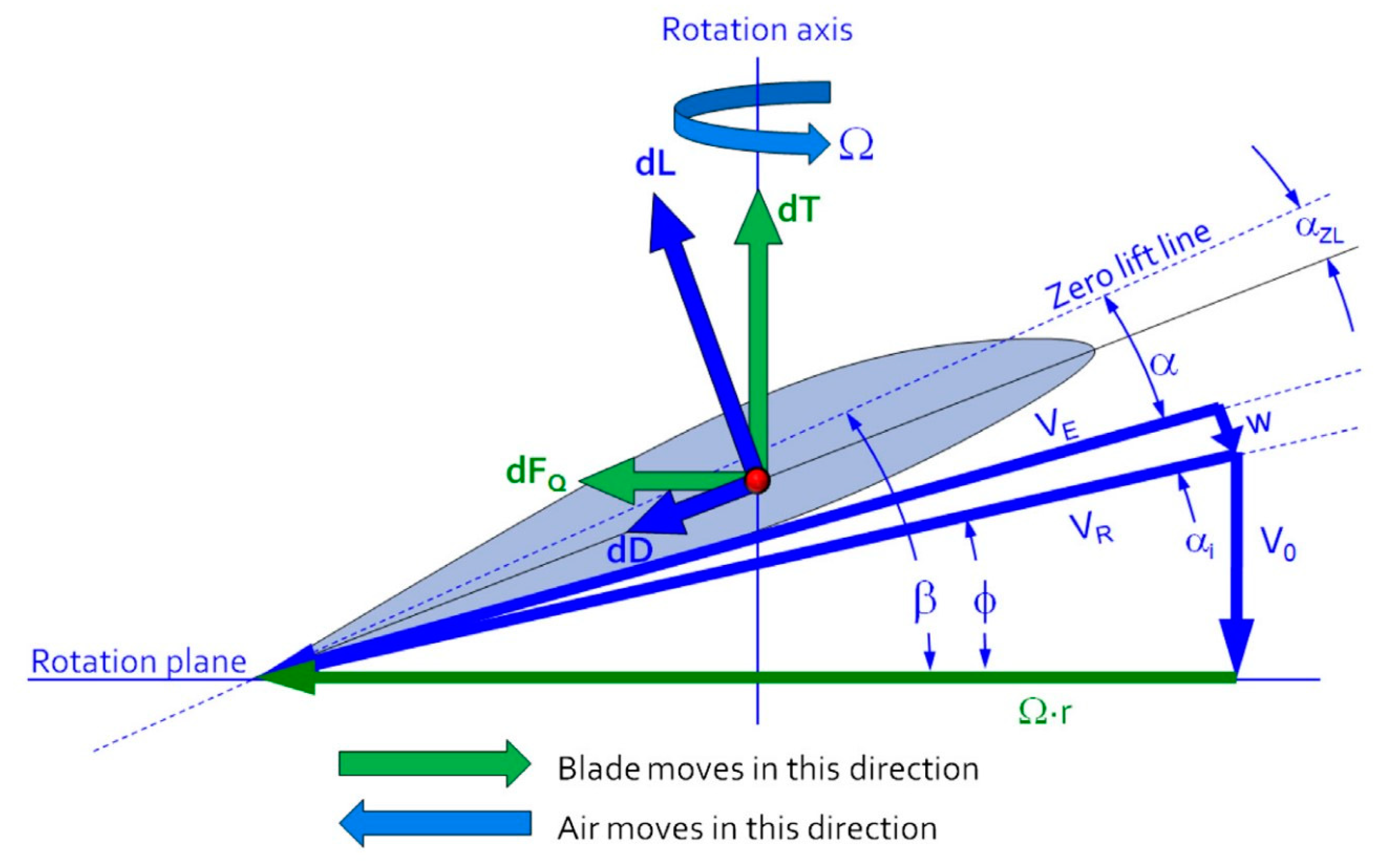
Figure 2.20.
Flow Angles Calculation.
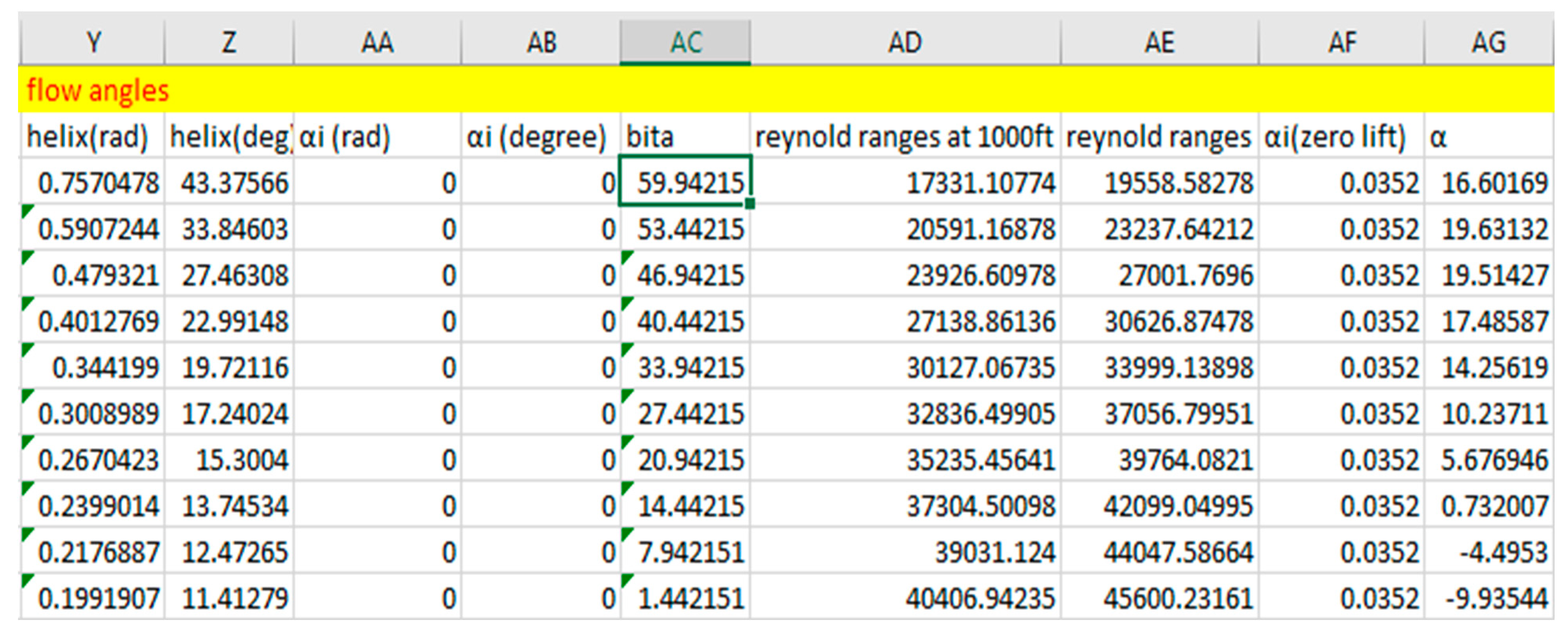
- 15.
- Helix angle (: The helix angle is the angle between the relative velocity vector and the chord line. It varies along the length of the blade and at different radial positions. The helix angle is crucial for calculating the effective angle of attack, which is used to determine the lift and drag forces generated by the propeller.
- 16.
- Induced flow angle (αi): refers to the angle at which air flows behind a propeller due to the motion and rotation of the propeller itself. In this paper, the induced velocity will be calculated using actuator disk theory. It's important to note that under the blade element momentum theory, the induced velocity is assumed to be zero. Consequently, if the induced velocity is indeed zero, then the induced angle is also zero.
- 17.
- Geometric pitch angle (bita): Geometric pitch angle is an important parameter as it determines how the blade "bites" into the air and influences the angle of attack (the angle between the local airflow and the chord line of the blade element). The geometric pitch angle varies along the span of the blade and is usually adjusted to optimize the propeller's performance for different flight conditions and operational requirements.
- 18.
- The geometric pitch angle involves adjusting the twist of the propeller at various angles to achieve a suitable and efficient blade loading distribution. This adjustment entails more twist at the root and less at the tip to generate uniform thrust across different sections of the propeller. Two methods were considered for achieving this twist.
The first method involved using the maximum lift coefficient (Cl) and drag coefficient (Cd) against the airfoil's angle of attack to determine the angle of attack at each section. However, this method was not applied due to limitations in changing the required propeller torque when approaching the maximum values of Cl and Cd. While this method could enable the airfoil to operate at its maximum efficiency at different sections, it could lead to challenges in adjusting the torque.
Instead, the second method was chosen, which involved twisting the propeller blades within the range of 50-70 degrees at the hub and 10-20 degrees at the tip. This range was selected as it aligns with the typical propeller twist variations used in practice. Furthermore, this method allows for the optimization of the propeller in accordance with the engine's performance characteristics. During the calculations, variations in thrust, torque, and power can be observed.
Both the Clark Y and E63 airfoil propellers are subjected to linear twisting, ranging from 45- 70 degrees at the hub and 10 -20 degrees at the tip, based on the available torque of the engine.
- 19.
- Angle of Attack (α):Where, αi(zero lift) is the zero lift angle of attack. It is obtained from the airfoil result on xflr5below. If the xflfr5 result doesn’t show the angle of attack at zero lift, then interpolation must be made between two angles that are closer to zero lift angle of attack. The only values provided above was just for the Clark Y airfoils only.AOA = bita − αi − ϕ- αi(zero lift)
- 20.
- Reynolds number: The Reynolds number is a dimensionless parameter commonly used in fluid dynamics and aerodynamics, including airfoil calculations. It plays a crucial role because it assists in determining the flow regime and predicting the behavior of airflow around an airfoil. This parameter aids in visualizing how an airfoil functions under specific altitudes or flow conditions. For this analysis, both the Clark Y and E63 airfoils were tested using XFLR5 software, with maximum flow conditions corresponding to Reynolds numbers of 46,000 at sea level and 41,000 at 1000 feet altitude.
2.4. AIRFOIL PROPERTIES CALCULATION
Figure 2.21.
Pressure Distribution On Xflr 5 For Clark Y And E63 Airfoil.
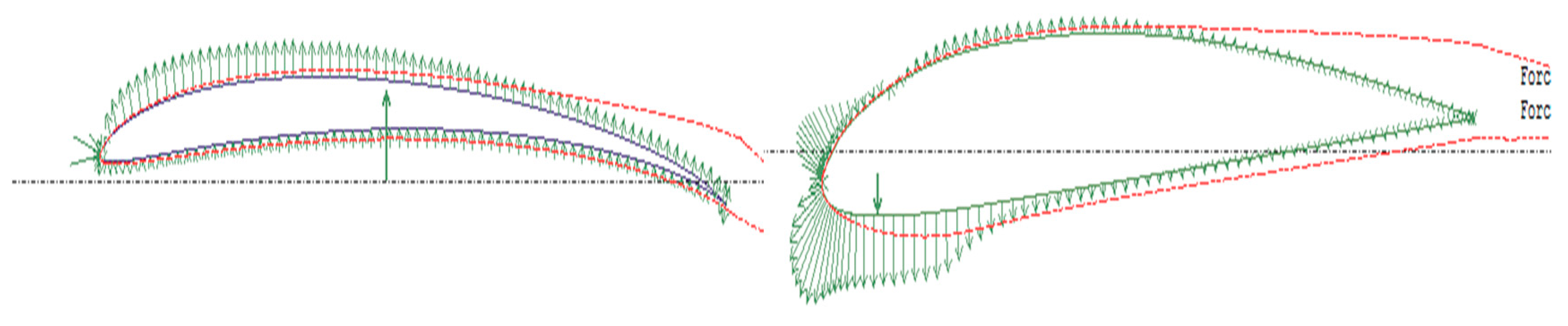
Figure 2.22.
Clark Y Airfoil.
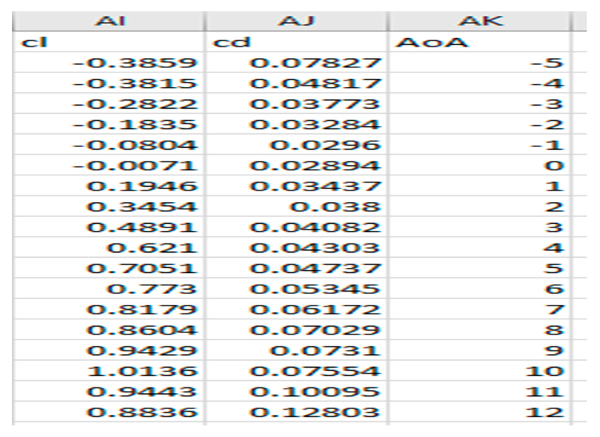
Figure 2.23.
E63 AIRFOIL.
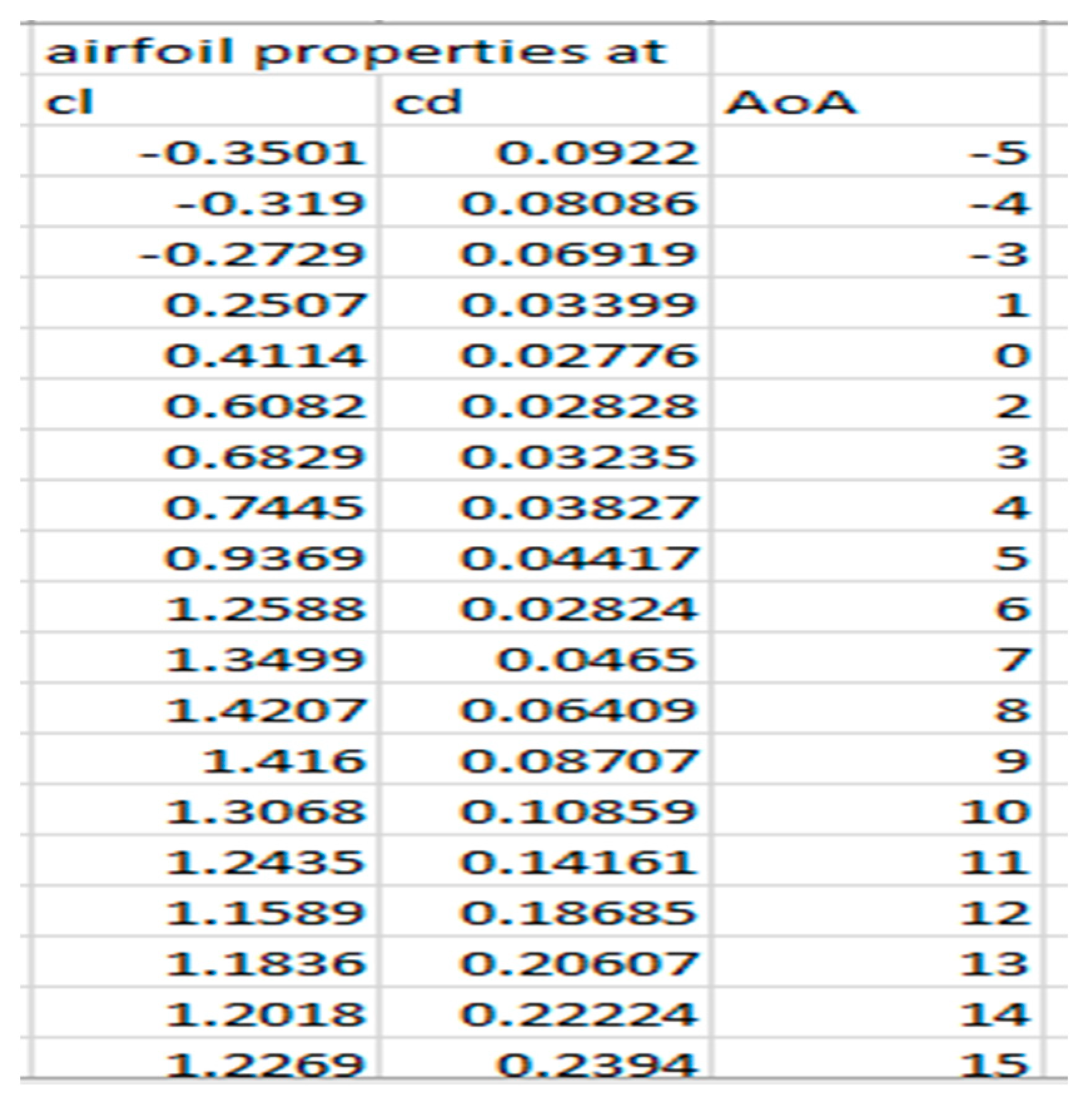
- 21.
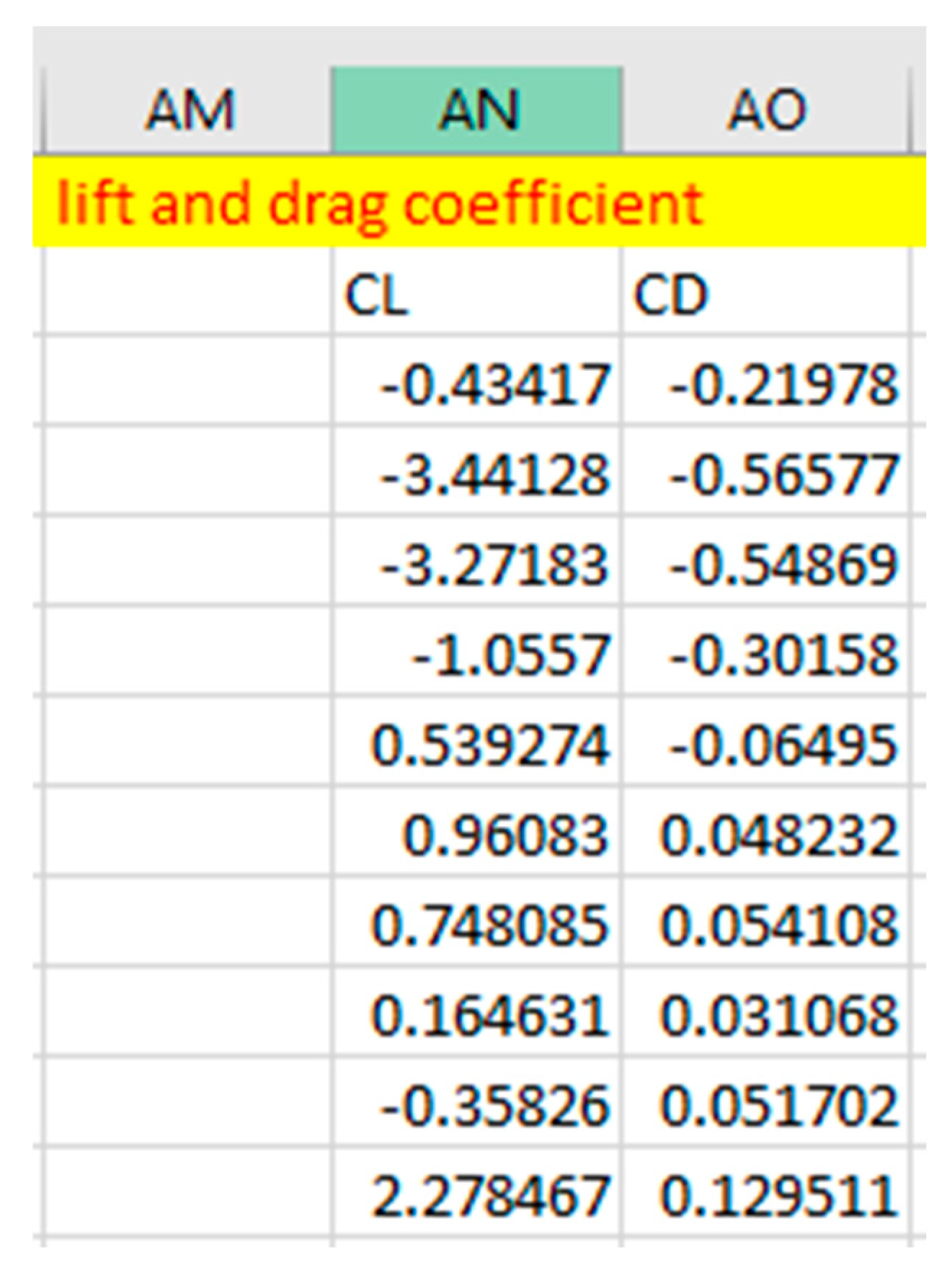
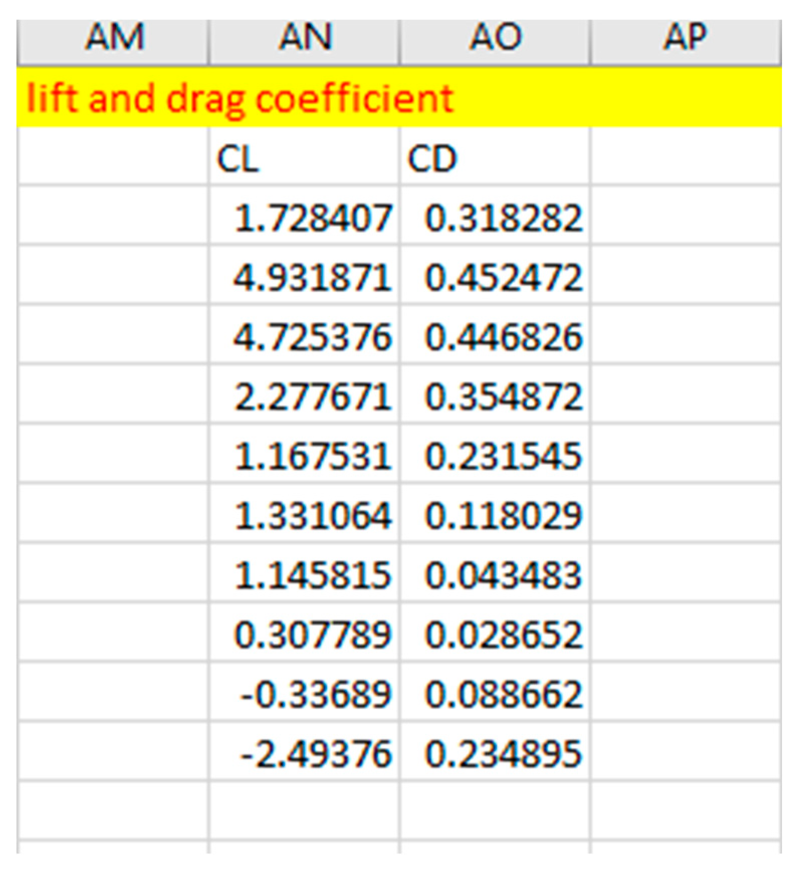
- Lift and Drag coefficient: Cl quantify the efficiency with which an airfoil generates lift, making it a crucial parameter in airfoil analysis and design. On the other hand, Cd quantifies the amount of drag produced by an airfoil during its movement through the air. Lower Cd values indicate reduced drag and higher aerodynamic efficiency. These values are determined through airfoil calculations. To obtain Cl and Cd values at various sections of the propeller blade, a polynomial fitting is performed using the results obtained from the lift and drag coefficients of the airfoils.
Figure 2.24.
Cl And CD For Clark Y Airfoil.
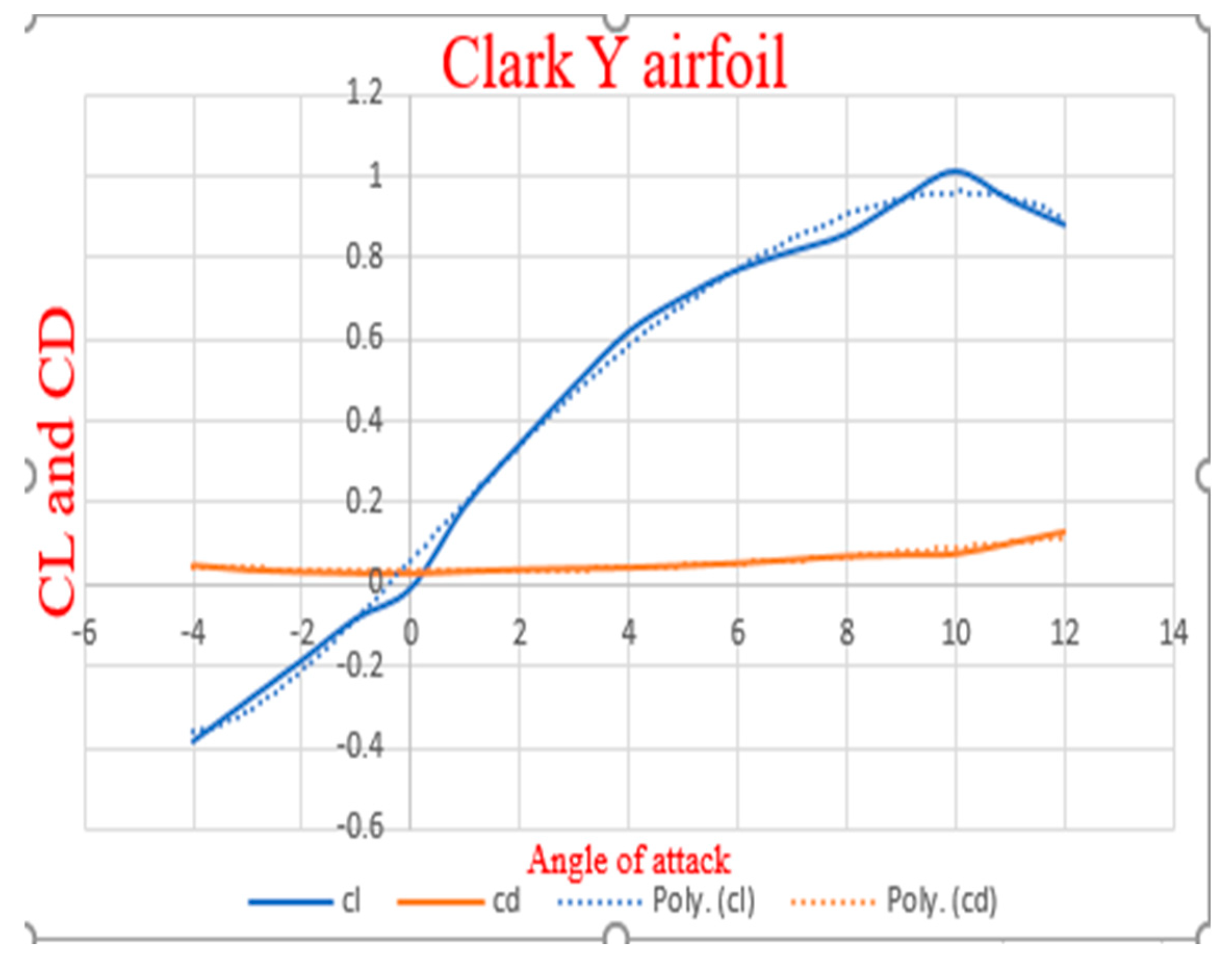
Figure 2.25.
Cl And CD For E63 Airfoil.
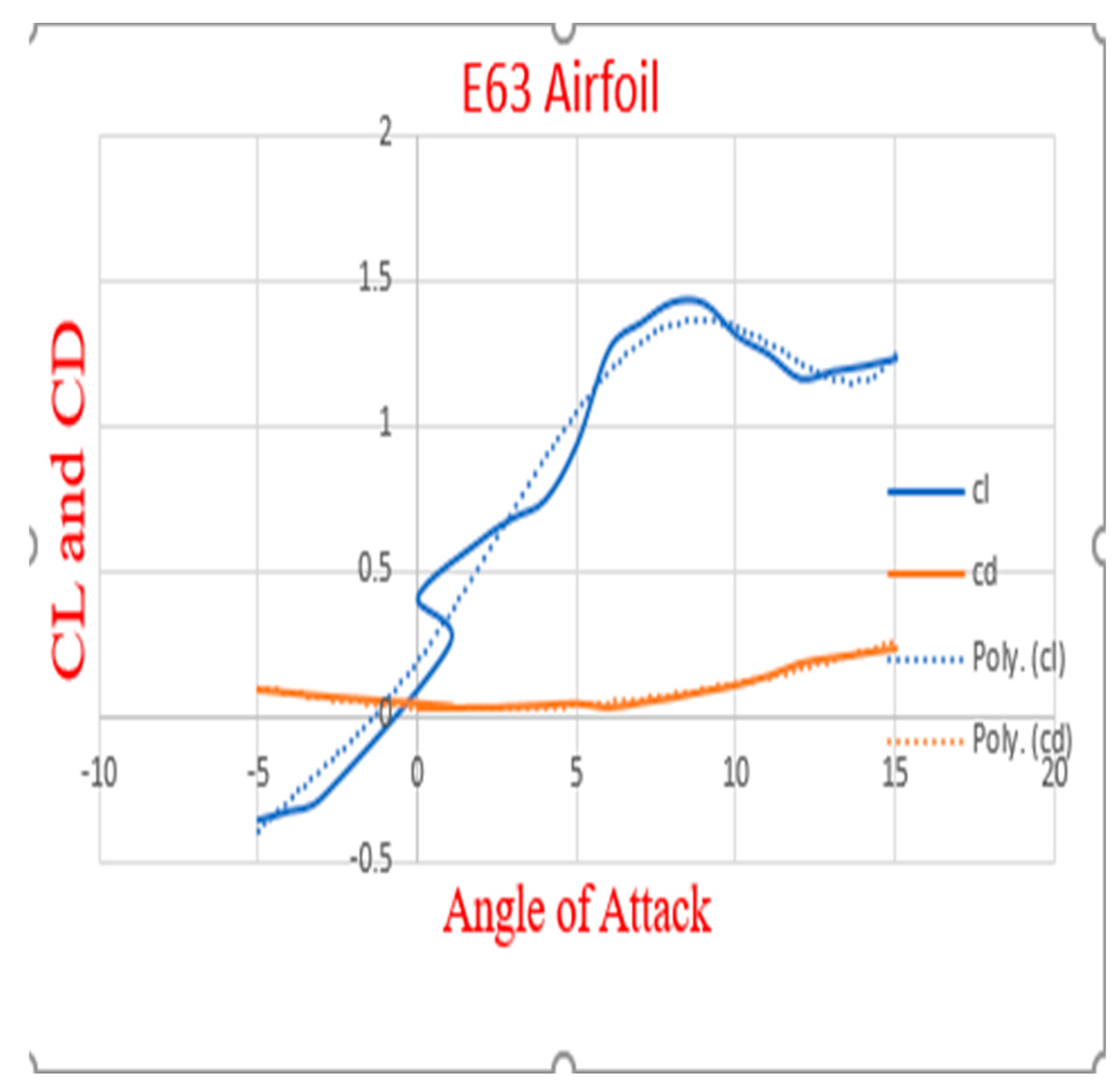
The polynomial fitting equation derived from the plotted graph above is used to derive the equations for the propeller's Cl and Cd as shown below."For Clark Y airfoil:
For E63 airfoil:
2.5. BLADE ELEMENT DIFFERENTIAL
Blade differential shows the aerodynamic performance of each section of the propeller blade. It shows how the lift, drag, power, torque and thrust varies along each section of the propeller blade.
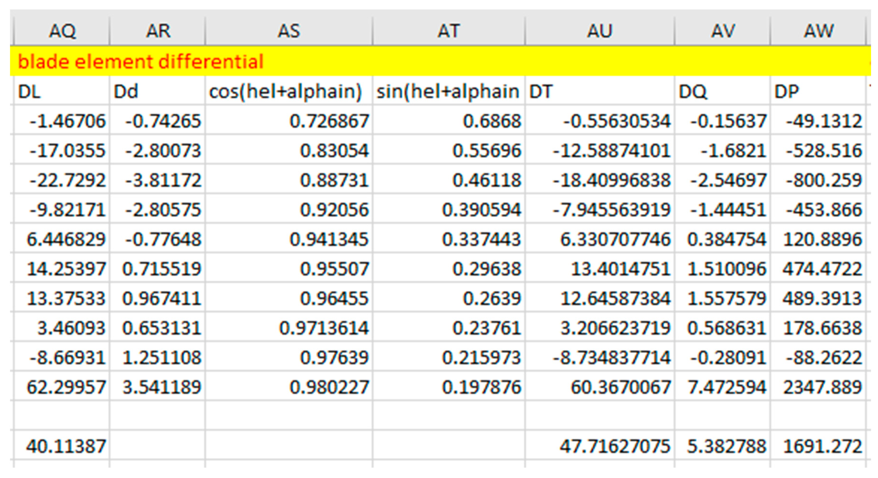
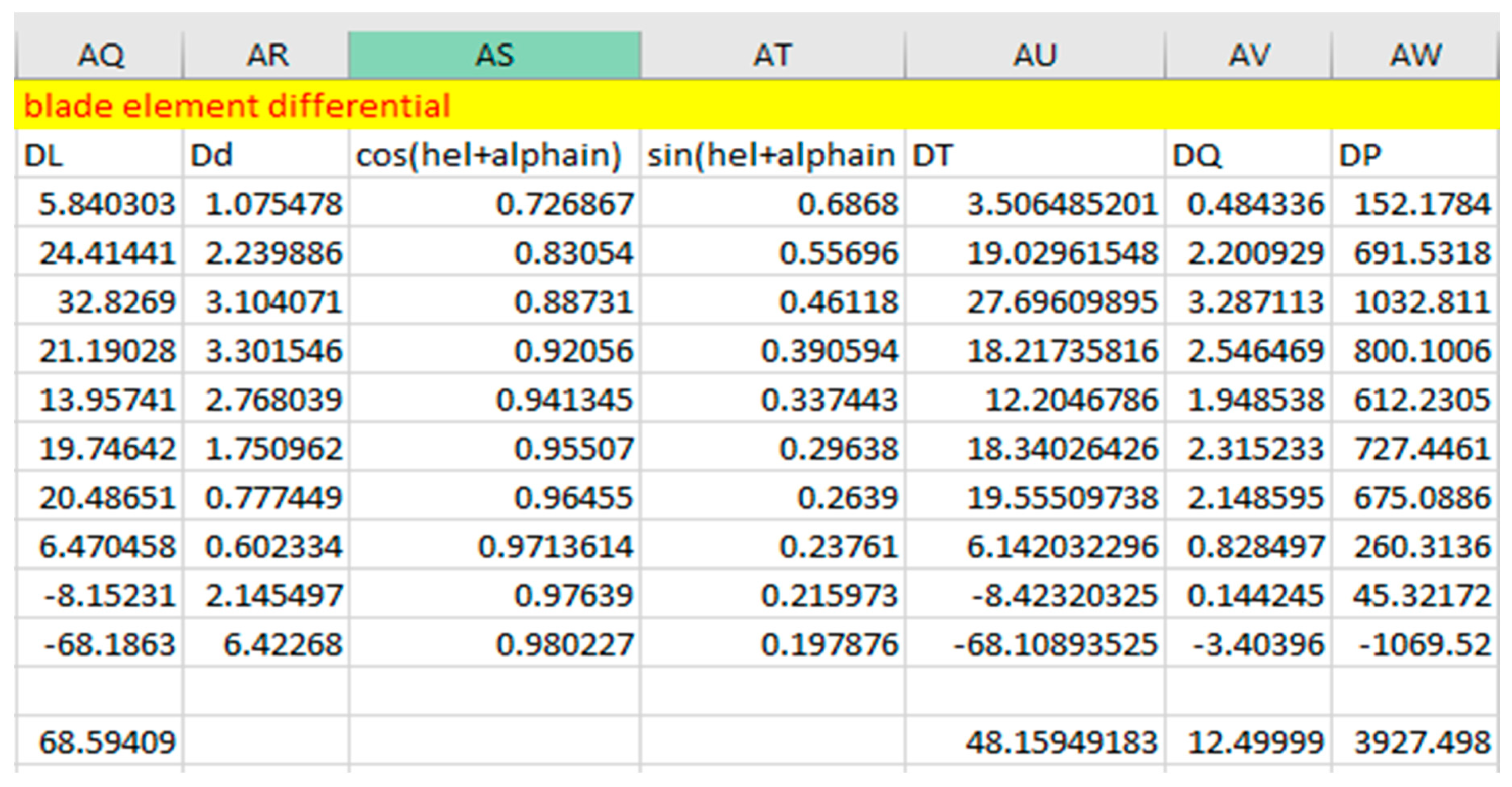
Figure 2.28.
Blade differential using Clark Y airfoil.
Figure 2.29.
Blade Differential Using E63 Airfoil.
Blade differential parameters ae gotten from the following equations:
- 22.
- Differential lift = dL =
- 23.
-
Differential Drag =dD =Where V is the propeller rotational speed.is the coefficient of lift and drag from the polynomial fitting equation.
- 24.
- Differential Thrust = dT = dLcos ( + dDsin( + )
- 25.
- Differential Torque = dQ = r[dLsin ( + dDcos ( + ]
- 26.
- Differential Power = dP =r[dLsin ( + dDcos ( + ]
2.6. PROPELLER DESIGN PERFORMANCE
This refers to the estimation and analysis of how a propeller will perform under various operating conditions, providing valuable insights into thrust, power, lift, drag, and propeller efficiency.
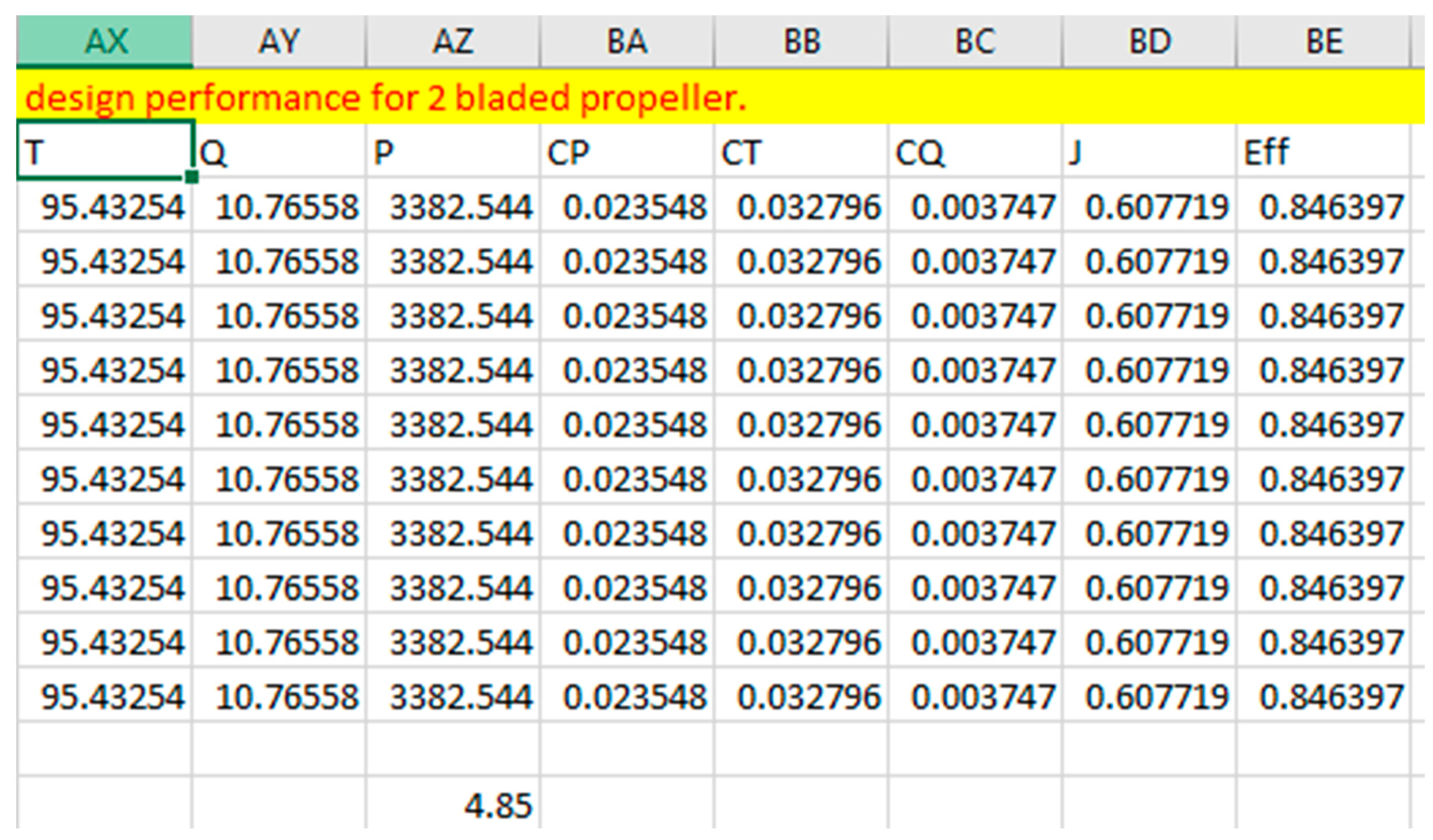
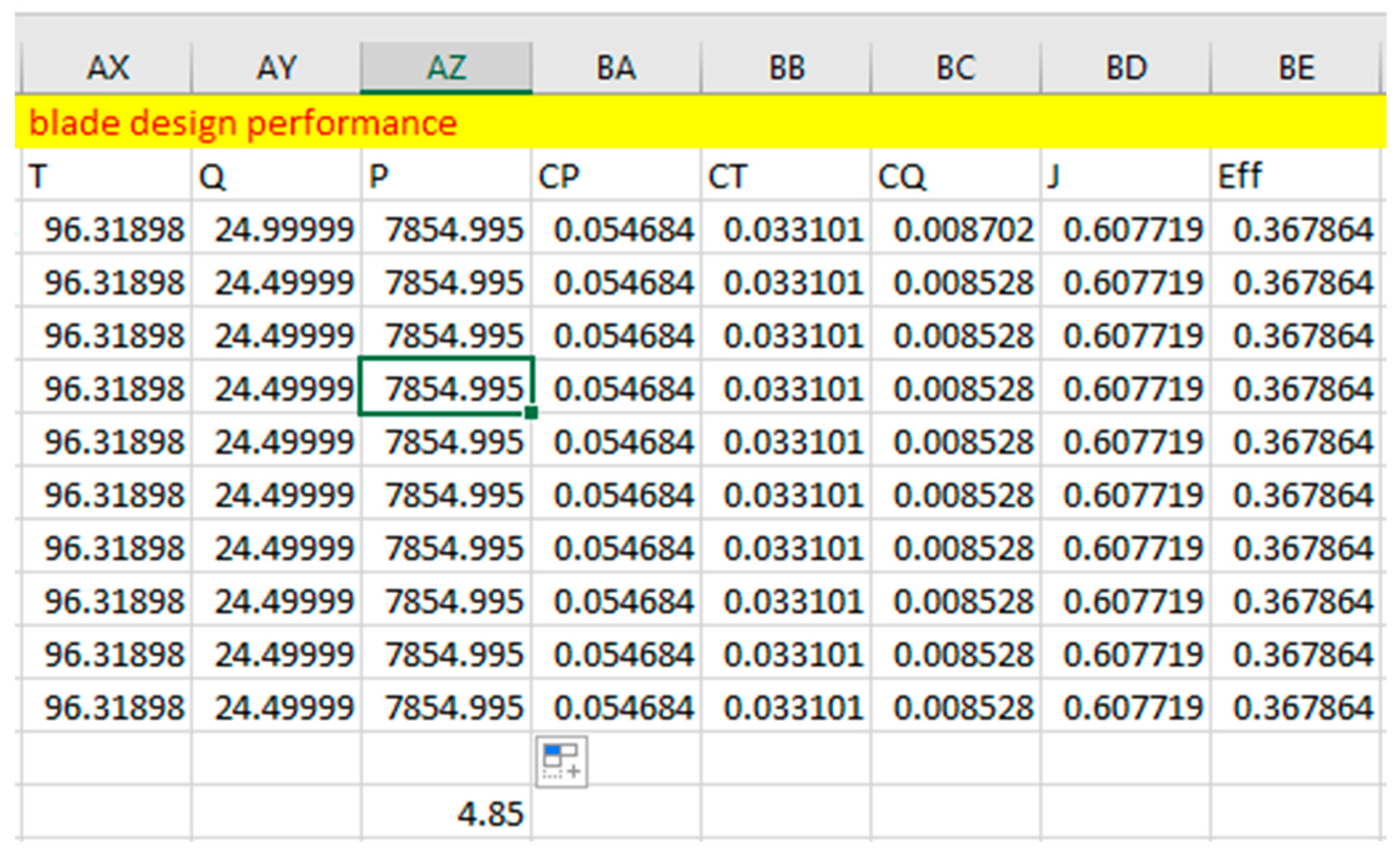
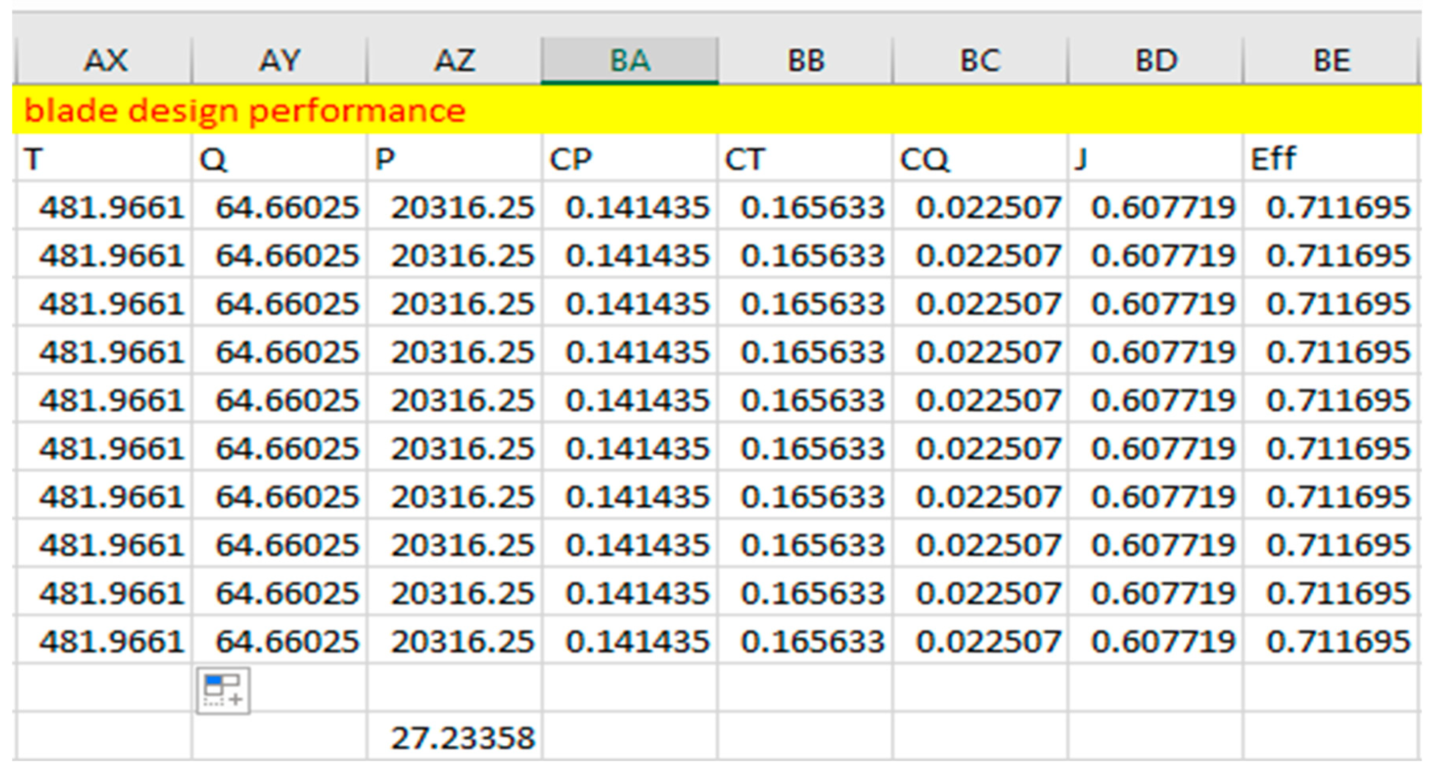
Figure 2.30.
Propeller Design Performance Using Clark Y Airfoil, Twisted At 65 Degrees At The Root And 10 Degrees At The Tip.
Figure 2.30.
Propeller Design Performance Using Clark Y Airfoil, Twisted At 65 Degrees At The Root And 10 Degrees At The Tip.
Figure 2.31.
Propeller Design Performance Using E63 Airfoil, Twisted At 65 Degrees At The Root And 10 Degrees At The Tip.
Figure 2.31.
Propeller Design Performance Using E63 Airfoil, Twisted At 65 Degrees At The Root And 10 Degrees At The Tip.
Figure 2.32.
Propeller Design Performance Using E63 Airfoil, Twisted At 70 Degrees At The Root And 10 Degrees At The Tip.
Figure 2.32.
Propeller Design Performance Using E63 Airfoil, Twisted At 70 Degrees At The Root And 10 Degrees At The Tip.
- 27.
- Thrust (T) = no of propeller blade x Sum of thrust differential (dT)
- 28.
- Torque (Q) = no of propeller blade x Sum of Torque differential (dT)
- 29.
- Power (P) = no of propeller blade x Sum of power differential (dT)
- 30.
- Power Coefficient = =
- 31.
- Thrust Coefficient = =
- 32.
- Torque Coefficient = =
- 33.
- Advance Ratio = J =
- 34.
-
Propeller Efficiency = = JWhere D is the propeller diameter
DESIGN ON QLADE SOFTWARE
QBlade is a specialized open-source software tool designed for the aerodynamic and structural analysis and design of wind turbine blades. While QBlade is primarily focused on wind turbine blades, it can also be used for propeller analysis and design in certain applications, such as small-scale wind turbines or other rotor systems. In this paper, the Qblade software is used to design the propeller, to visualize how the propeller looks like.
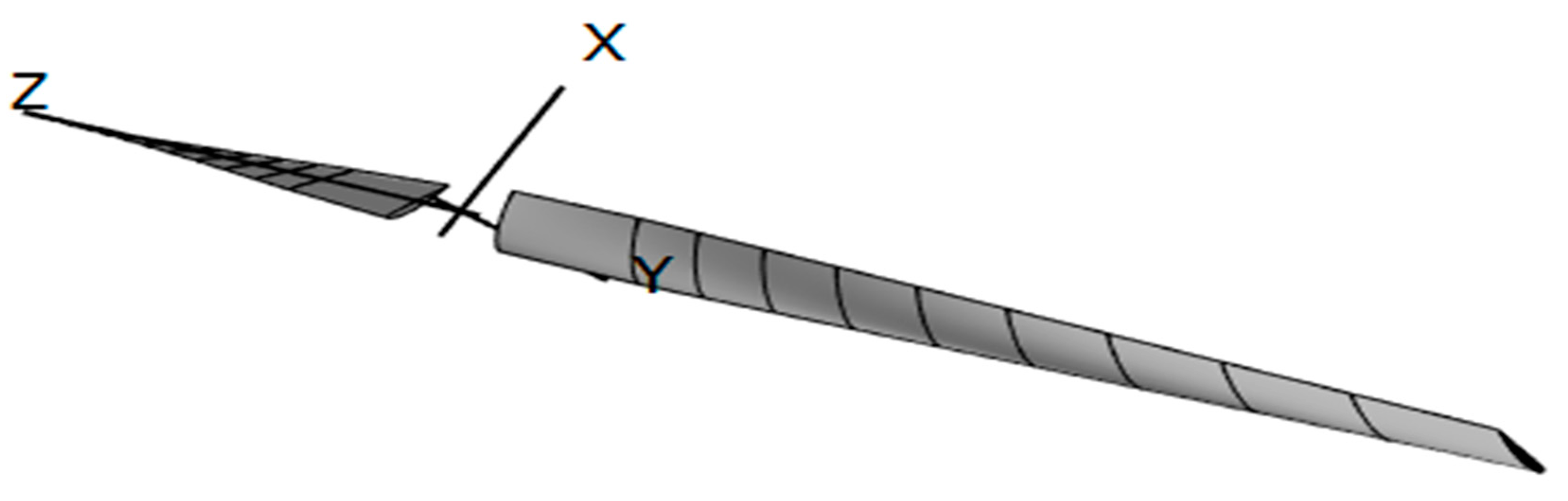
Figure 2.33.
Propeller design using Qblade.
INDUCED VELOCITY
Induced velocity is the velocity of air around the propeller blade. It refers to the change in velocity of the air or fluid caused by the action of the propeller blades. It is a critical factor in propeller design and analysis, affecting thrust, lift, drag, and overall aerodynamic performance. It can be visualized when calculating using actuator disk theory. Actuator Disk Theory considers air speed around the propeller blade over a hollow section. The induced velocity is not considered in this blade element momentum theory analyses which makes the value of thrust, torque, and power needed by the propeller increase to some specific number of values or decreases to some certain number of values. The Actuator Disk Theory was used to calculate the effect of induced velocity on the propeller blade
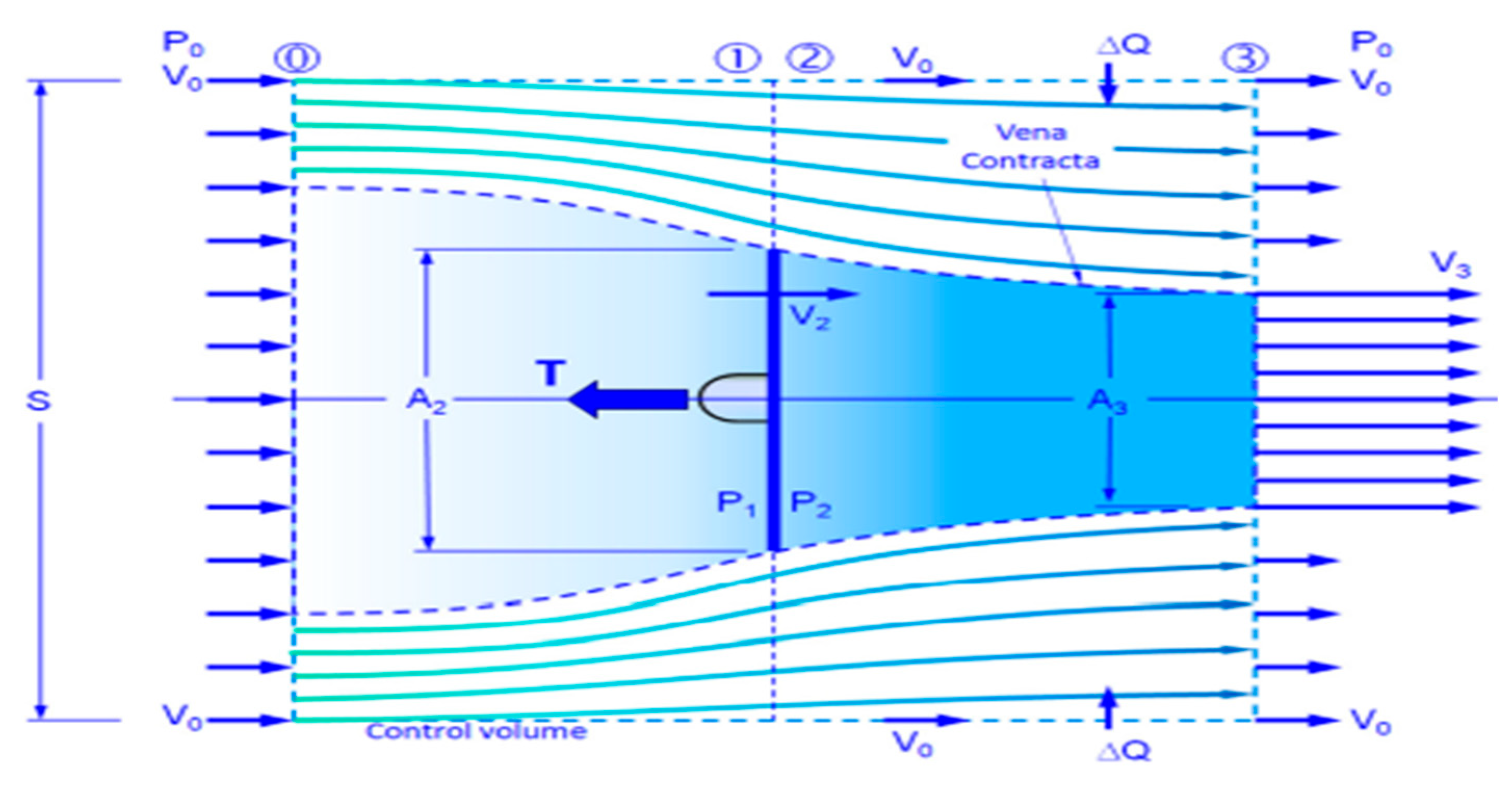
Figure 2.34.
Propeller Velocity Distribution.
The following equations are used in calculating the induced velocity of a propeller.
Effective resultant velocity:
Using Newton raphson iterative method for the calculation of induced velocity. The initial induced velocity is asumed to be 1m/s for the clculation. All formulas are inserted to excel for better calculation.
where = Number of propeller blade .
Since the result from the E63 airfoil is much than our engine parameters, the induced velocity is not calculated for E63 airfoil
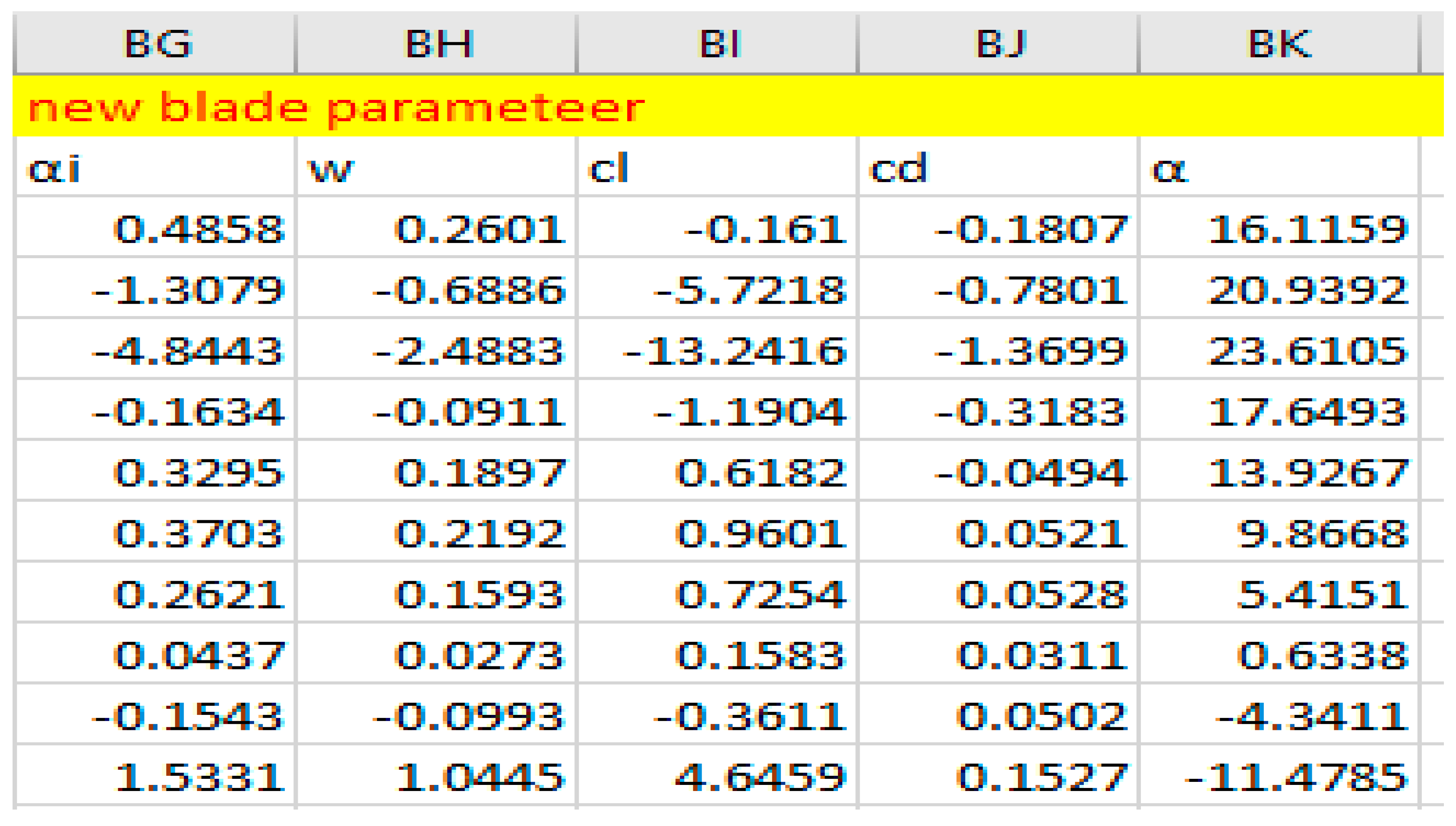
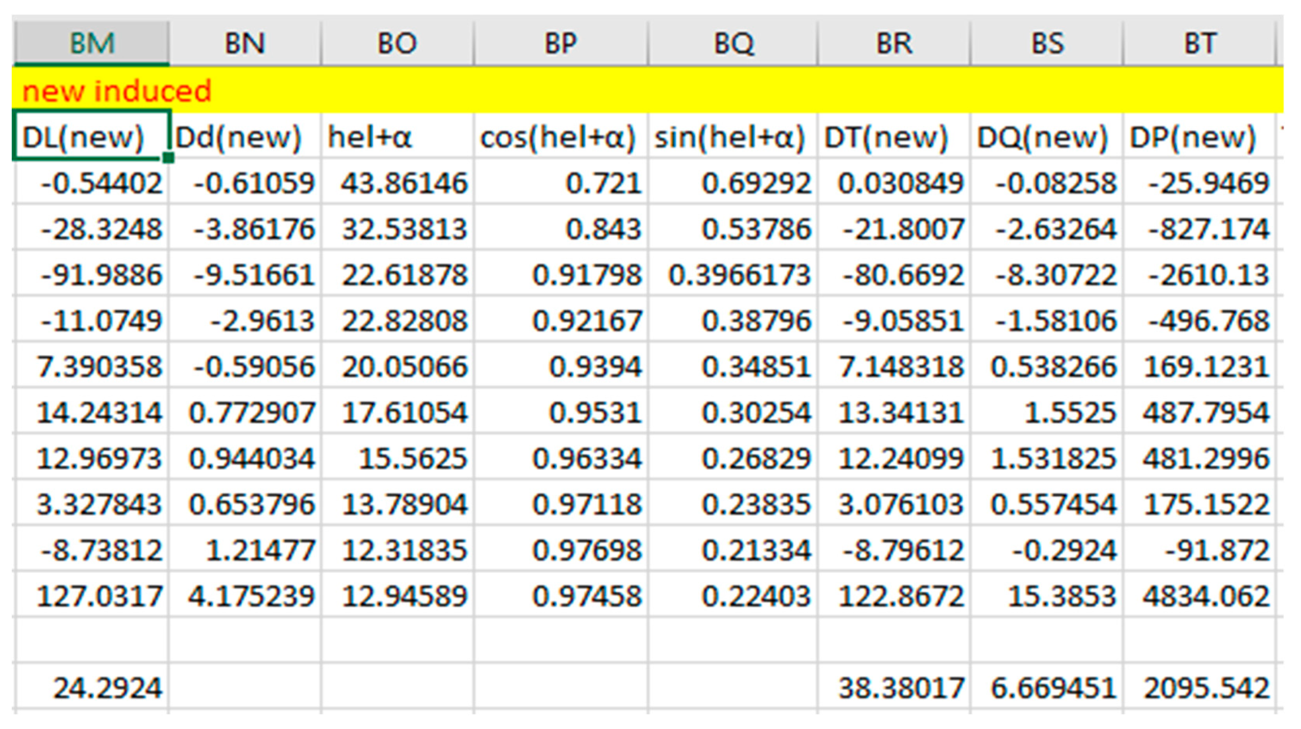
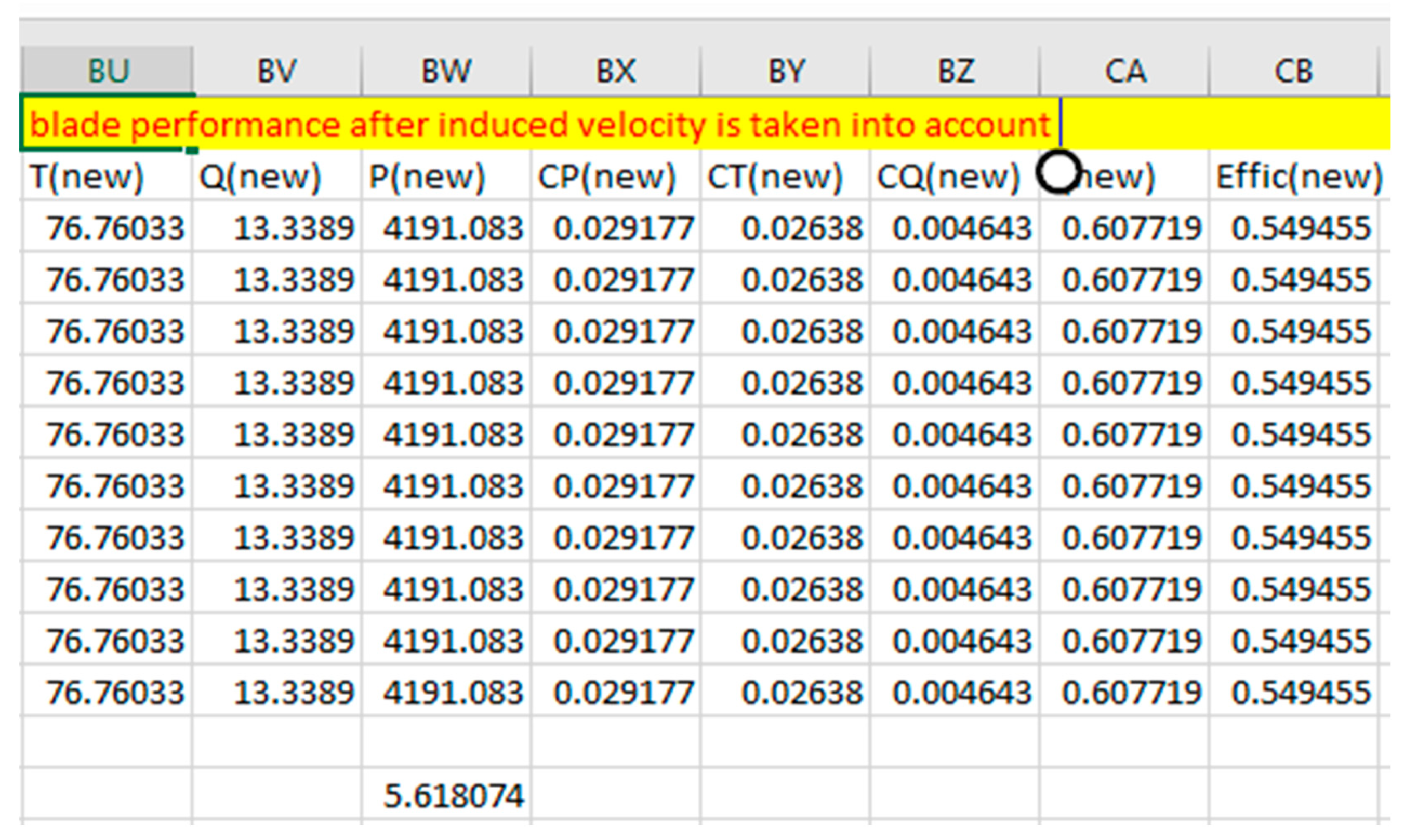
Figure 2.35.
New Blade Parameters Using Clark Y When Taking Induced Velocity Into Account.
Figure 2.36.
New Blade Differential Using Clark Y When Taking Induced Velocity Into Account.
Figure 2.37.
New Blade Performance Using Clark Y When Taking Induced Velocity Into Account.
3. RESULT
After conducting the following analysis, it becomes evident that numerous parameters influence the optimization and design of the propeller, especially the assumed design parameters. The process of designing a propeller to meet specific design criteria demands the expertise of individuals who have experience in design, optimization, and experimentation. Below, the result of the propeller analysis are shown.
3.1. AIRFOIL OPTIMIZATION RESULT
The coefficients of lift and drag, along with other airfoil parameters, were calculated for the Clark Y and E63 airfoils using XFLR5 software. Achieving convergence in the XFLR5 analysis is crucial for obtaining accurate results. This often requires adjusting the airfoil by repaneling it and reducing the step size. It's important to note that different airfoils, even when subjected to the same Reynolds number, may not converge simultaneously. In such cases, a certain threshold must be reevaluated or reduced if convergence is not achieved within a specific number of steps.
The results are presented below. Notably, in contrast to the Clark Y airfoil, which initially ranged from -5 to 15 degrees, the XFLR5 analysis converged within a range of -5 to 12.5 degrees. On the other hand, the E63 airfoil achieved convergence within a range of -5 to 11 degrees. The XFLR5 results for the Clark Y airfoil are displayed below.
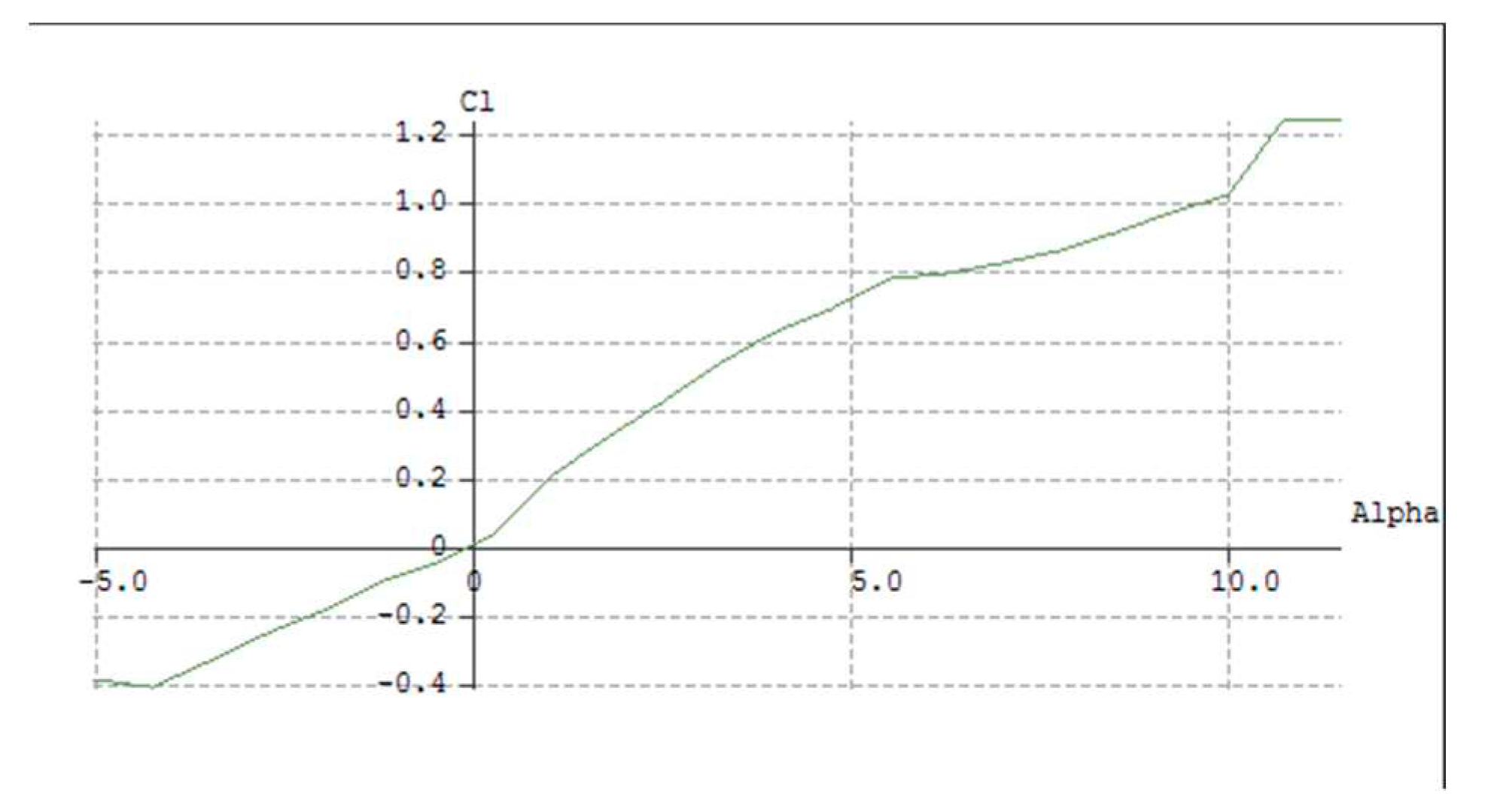
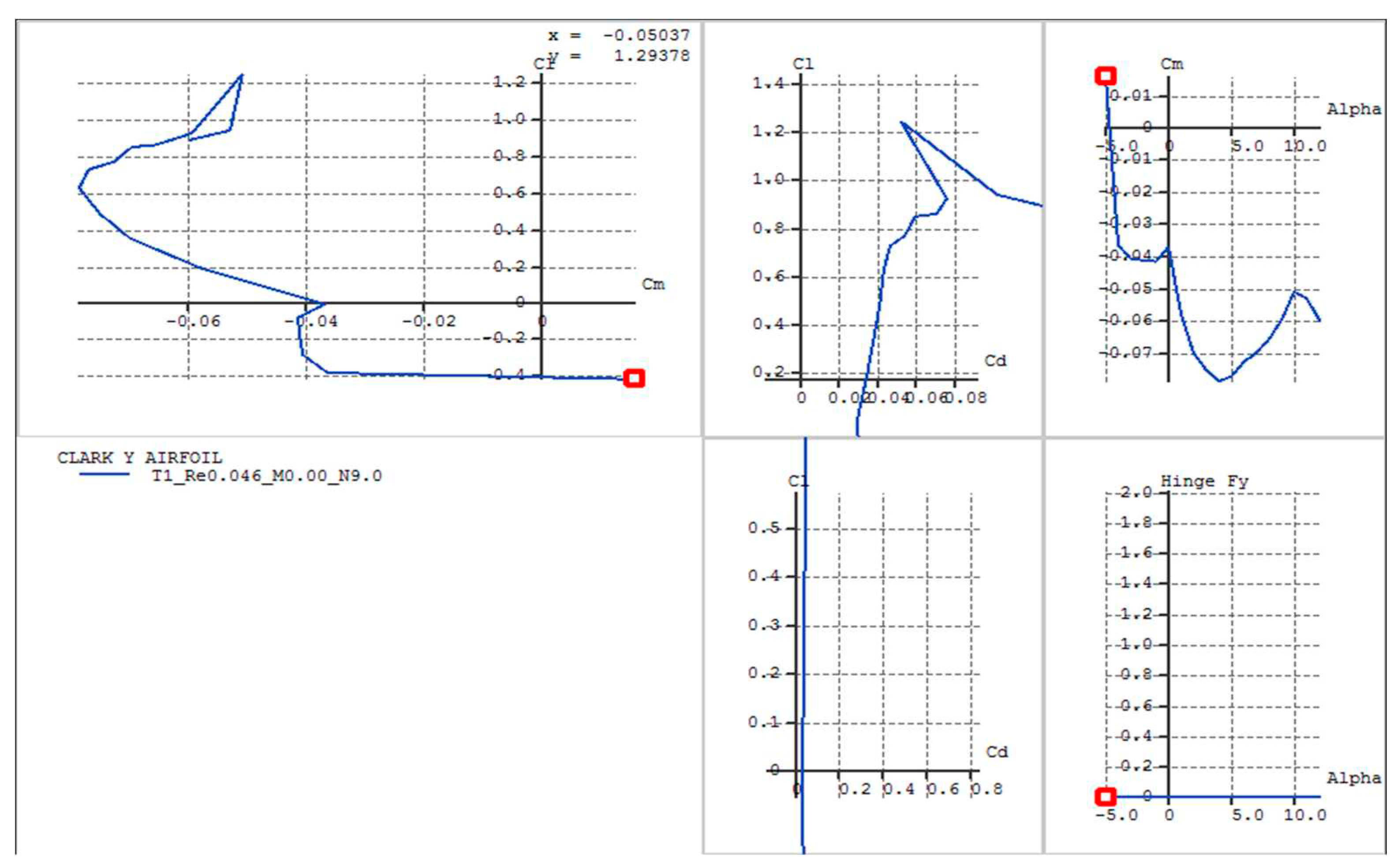
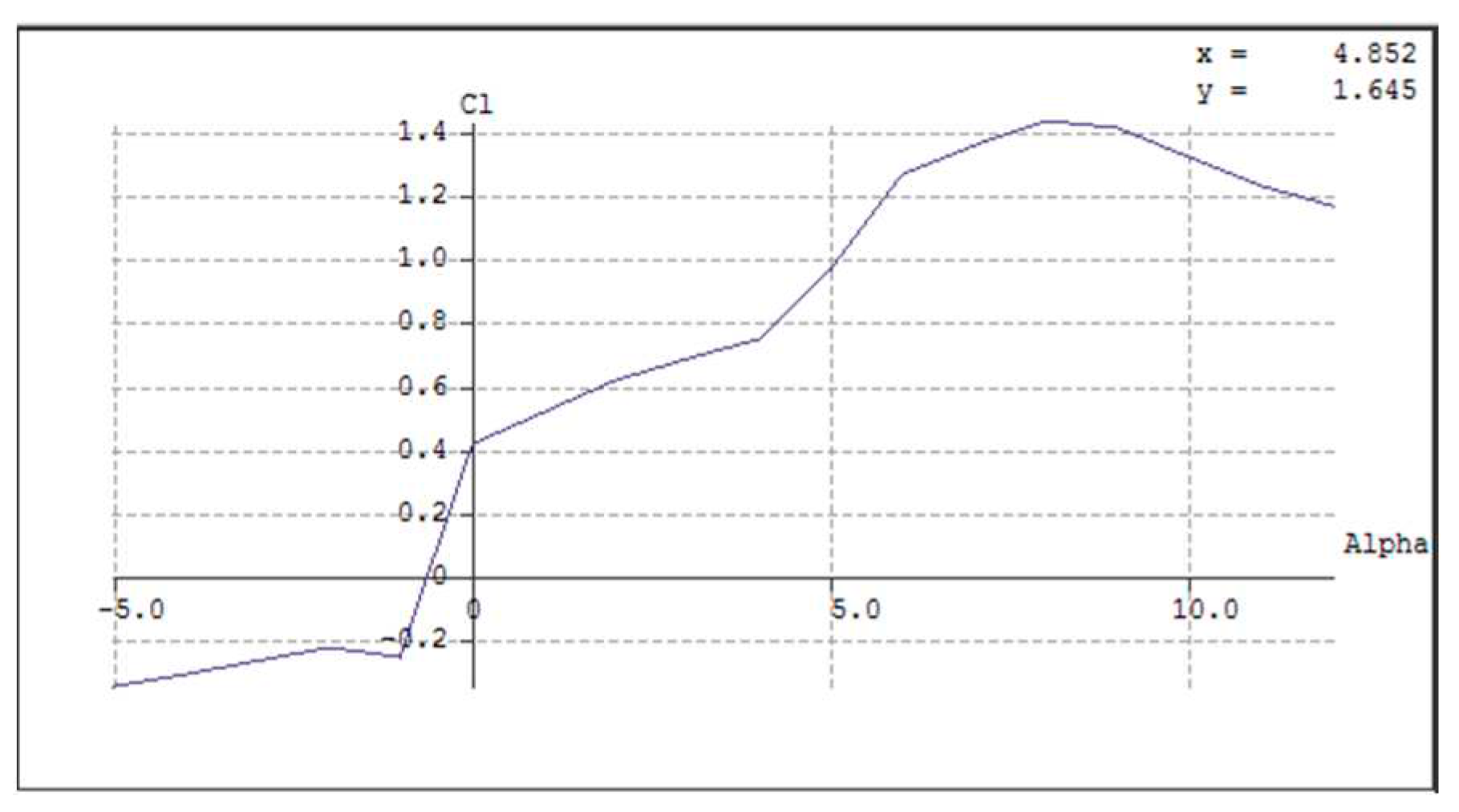
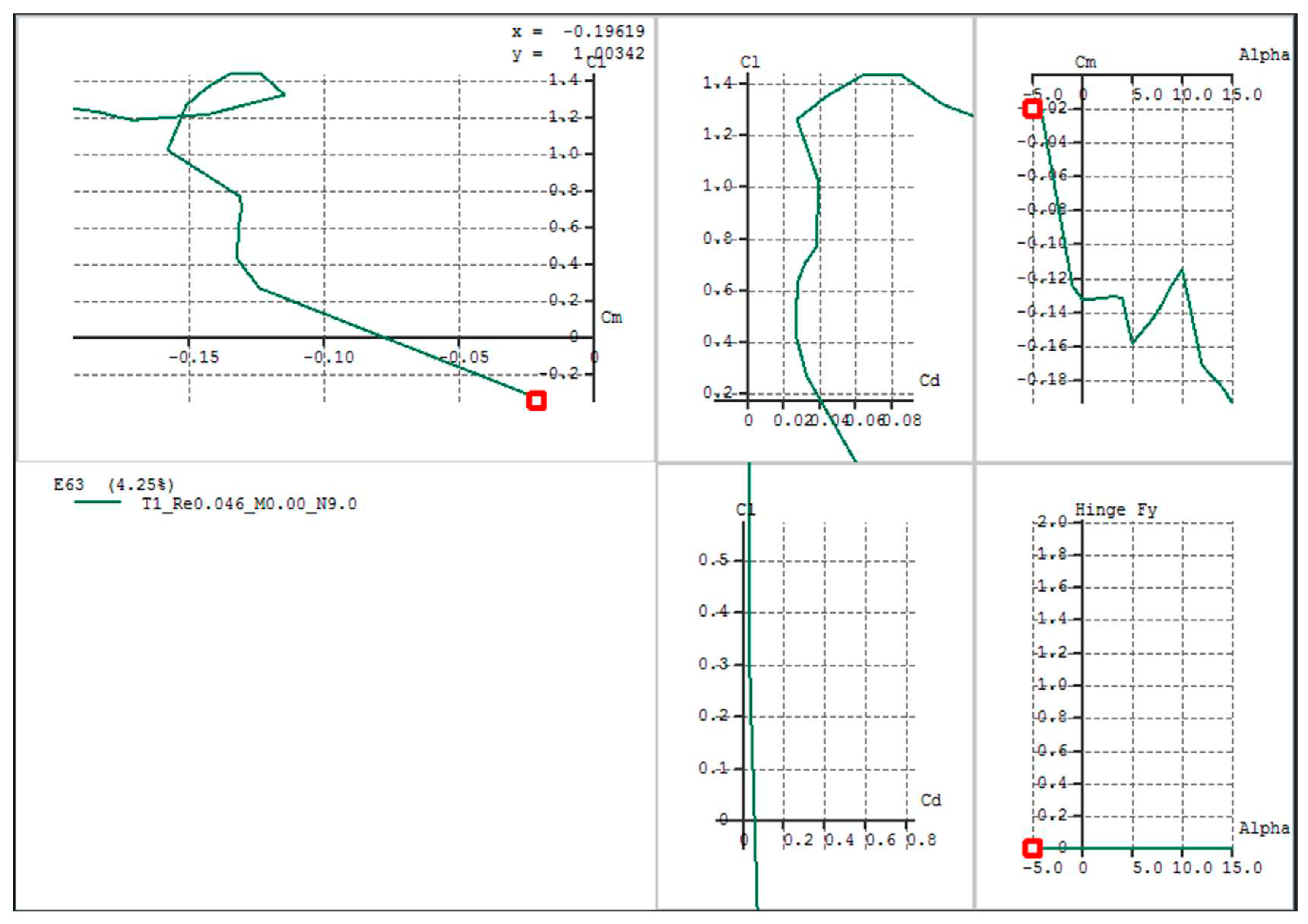
Figure 3.1.
Clark Y Airfoil Coefficient of Lift Vs Angle of Attack.
Figure 3.2.
Clark Y Polar Graphs.
Figure 3.3.
E63 Airfoil Coefficient of Lift Vs Angle of Attack.
Figure 3.4.
E63 Polar Graphs.
The E63 airfoil demonstrated higher efficiency compared to the Clark Y airfoil but required a greater amount of torque to operate efficiently. Due to its torque requirements, it may not be suitable for subsonic aircraft applications. In contrast, the Clark Y airfoil generated minimal torque but produced less thrust. To further analyze these airfoils, their properties were exported to Excel for data plotting. Polynomial fitting techniques were then applied to both airfoils to derive their respective polynomial equations. These polynomial equations are subsequently utilized to calculate the drag and lift coefficients at various sections along the propeller.
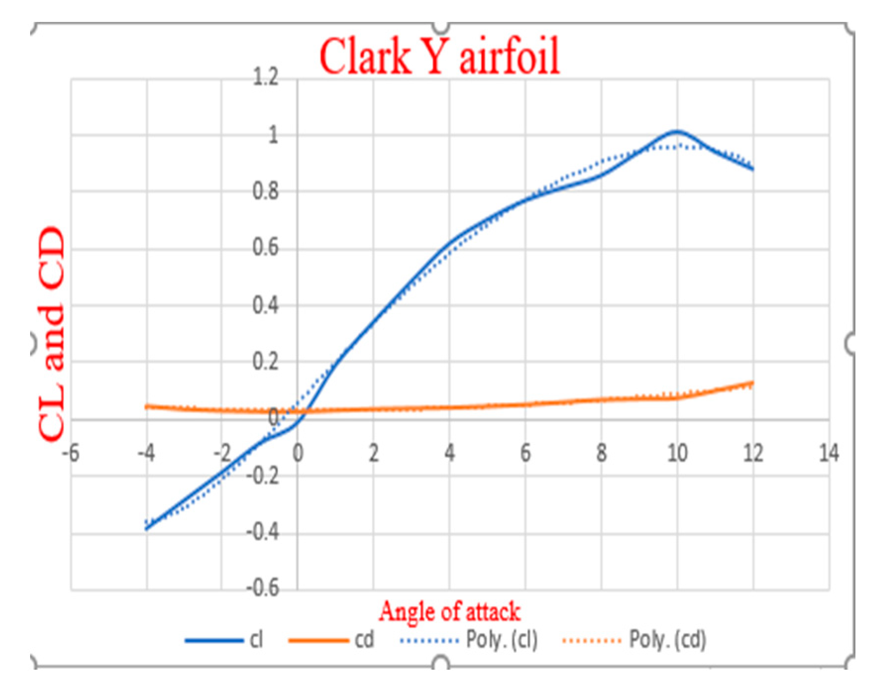
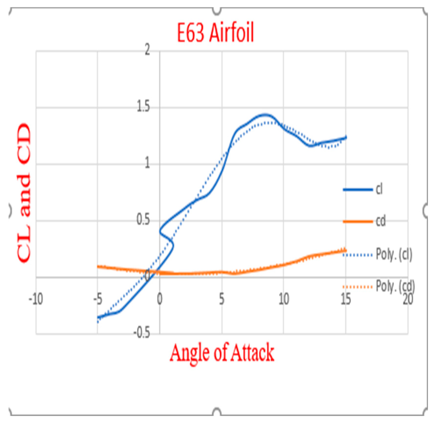
Figure 3.5.
Clark Y Coefficient Of Lift And Drag Result
Figure 3.6.
E63 Coefficient Of Lift And Drag Result.
3.2. PROPELLER TWISTING RESULT
The propeller using the Clark Y airfoil was twisted from 50 to 70 degrees at the root and 10 to 20 degrees at the tip. During this twisting process, various performance parameters were observed to visualize the effects of torque, thrust, lift, drag, and power at different twisting angles. The same principle was applied to the E63 airfoil. The Clark Y airfoil demonstrated increased efficiency when twisted to an angle of 65 degrees at the root and 10 degrees at the tip. In contrast, the E63 airfoil did not exhibit improved efficiency at these angles. The E63 airfoil achieved higher efficiency when twisted to an angle of 70 degrees at the root and 10 degrees at the tip. However, this increased efficiency came at the cost of higher torque, greater lift, increased power requirements, and higher drag, which might not align with the engine's efficiency. Twisting the E63 airfoil to less than 65 degrees at the hub resulted in a significant negative lift, reduced torque, and power, making it inefficient for generating forward thrust due to the negative lift and thrust. A similar effect was observed for the Clark Y airfoil, with negative lift occurring when the blade was twisted to less than 45 degrees at the hub.
In summary, it was observed that twisting the blade to a lesser angle at the hub led to a decrease in thrust to a negative value and required less torque and moderate power to rotate. In such cases, the torque required by the propeller might be significantly higher than the power needed, or vice versa. Achieving a balance between torque and power became challenging when twisting to less than 50 degrees at the hub and more than 20 degrees at the tip.
Considering these factors, the Clark Y airfoil was selected for the propeller design due to its lower torque requirements, sufficient thrust, and lower power demand compared to the E63 airfoil.
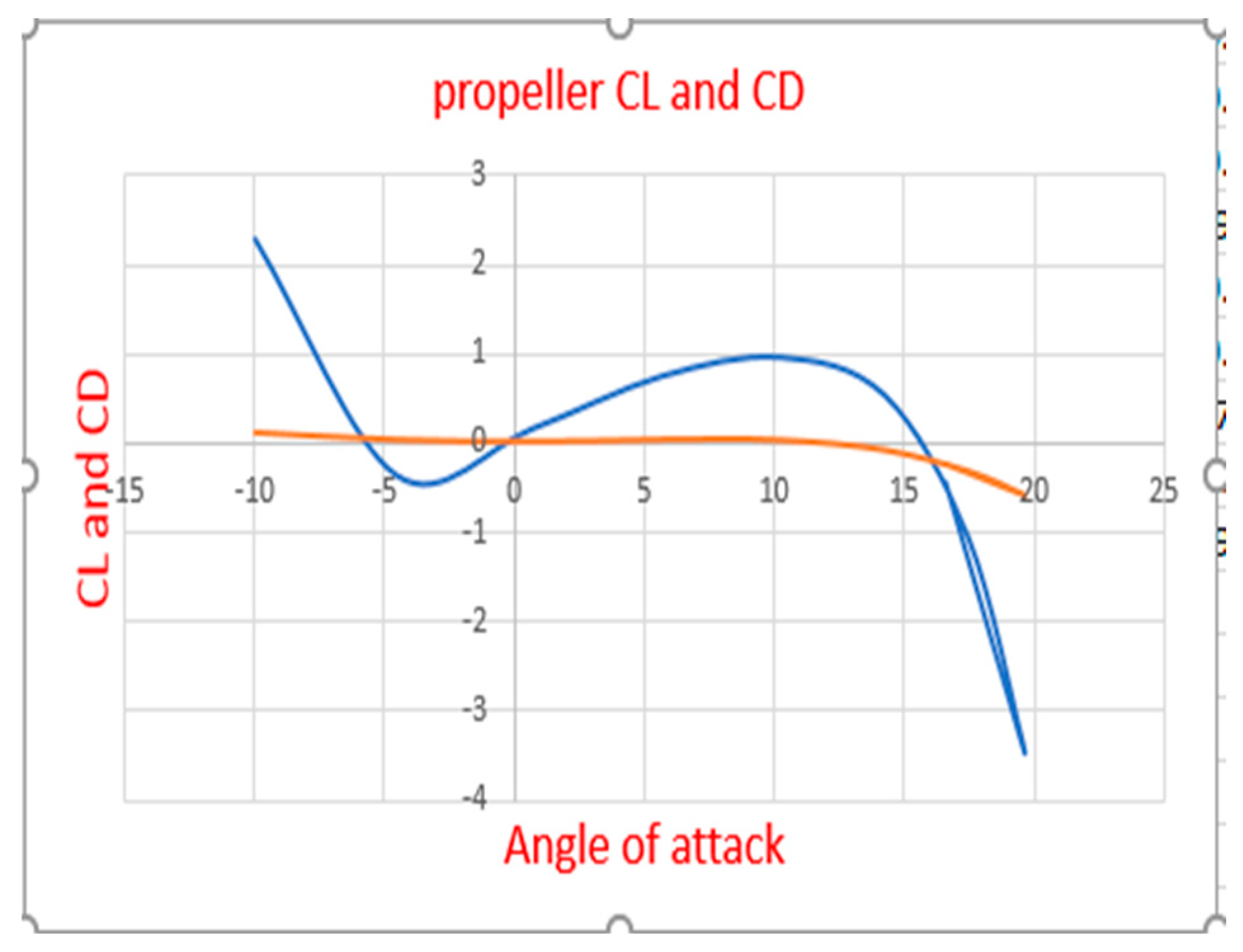
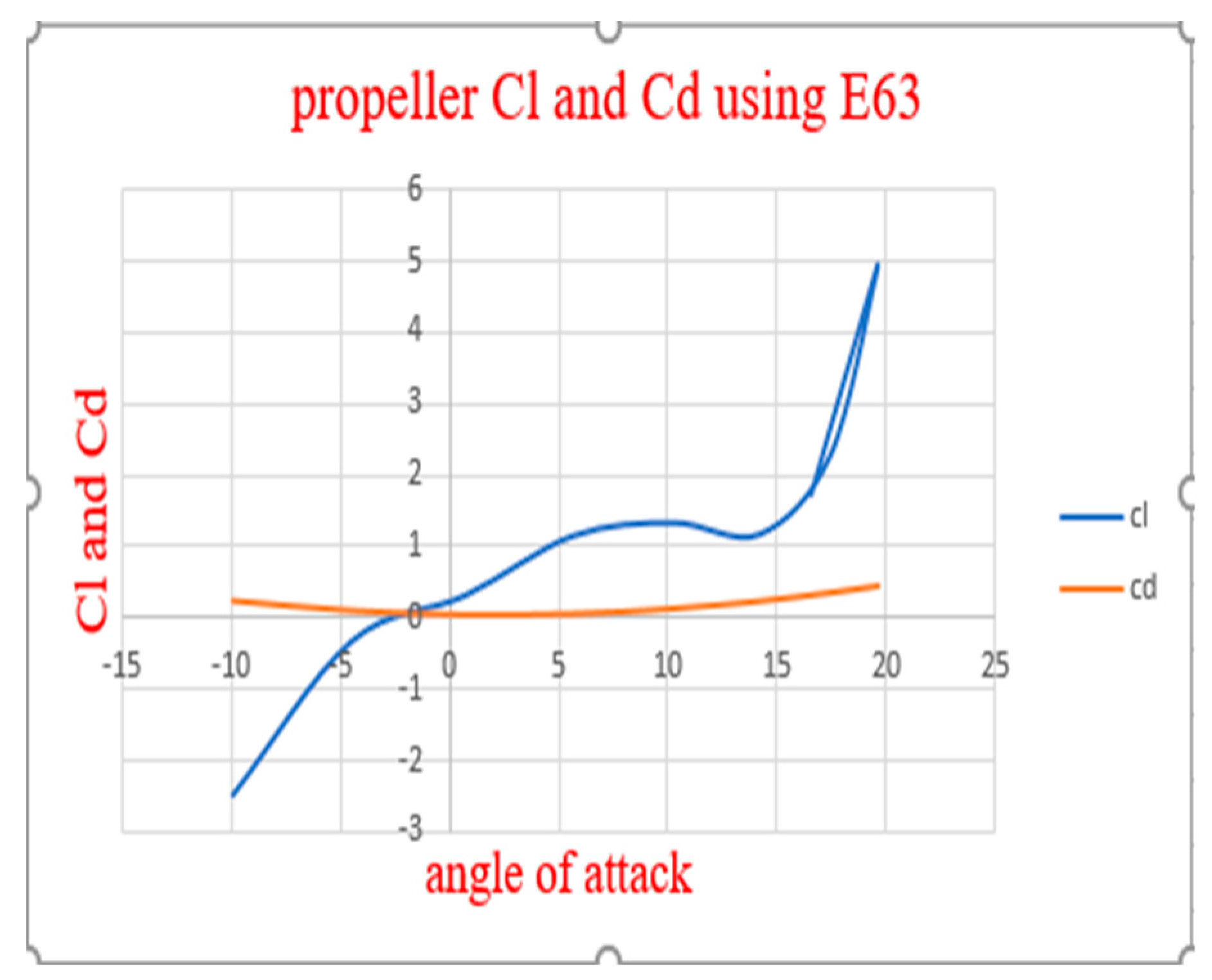
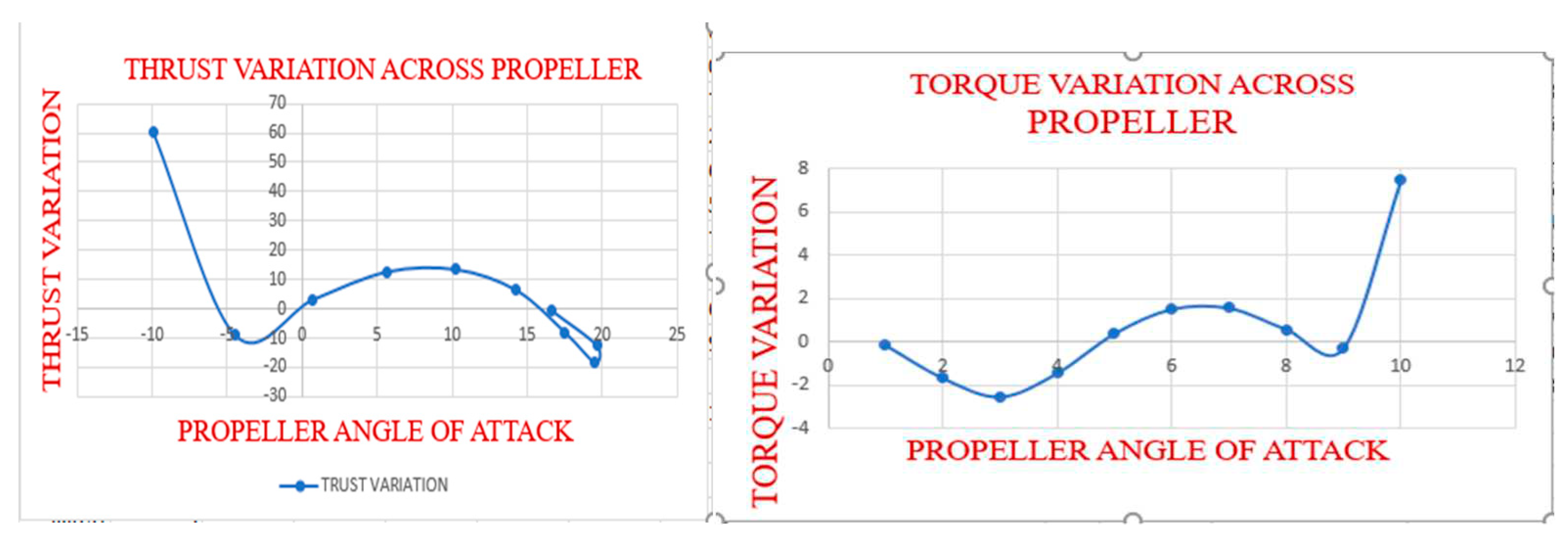
Figure 3.7.
Propeller Cl And Cd at Different Propeller Angles Of Attack Using Clark Y Airfoil.
Figure 3.8.
Propeller Cl And Cd At Different Propeller Angles Of Attack Using E63 Airfoil.
Figure 3.9.
Thrust And Torque Variation Across The Propeller Blade Using Clark Y Airfoil.
Since the values obtained for the E63 airfoil are higher and cannot be adjusted to be lower than the engine parameters, the graph showing thrust and torque variations for the E63 airfoil was omitted.
Induced Velocity Result
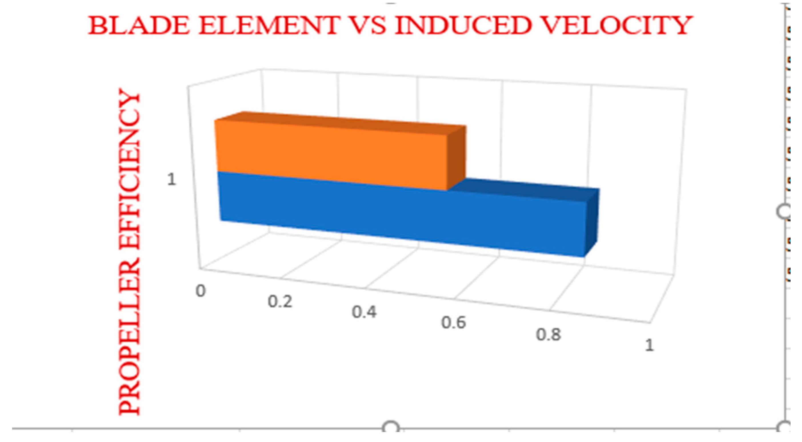
Figure 3.10.
Propeller Efficiency Using Clark Y (Induced Velocity Vs Without Induced).
The propeller efficiency reduced when the induced velocity is introduced from 0.846379 to 0.549455
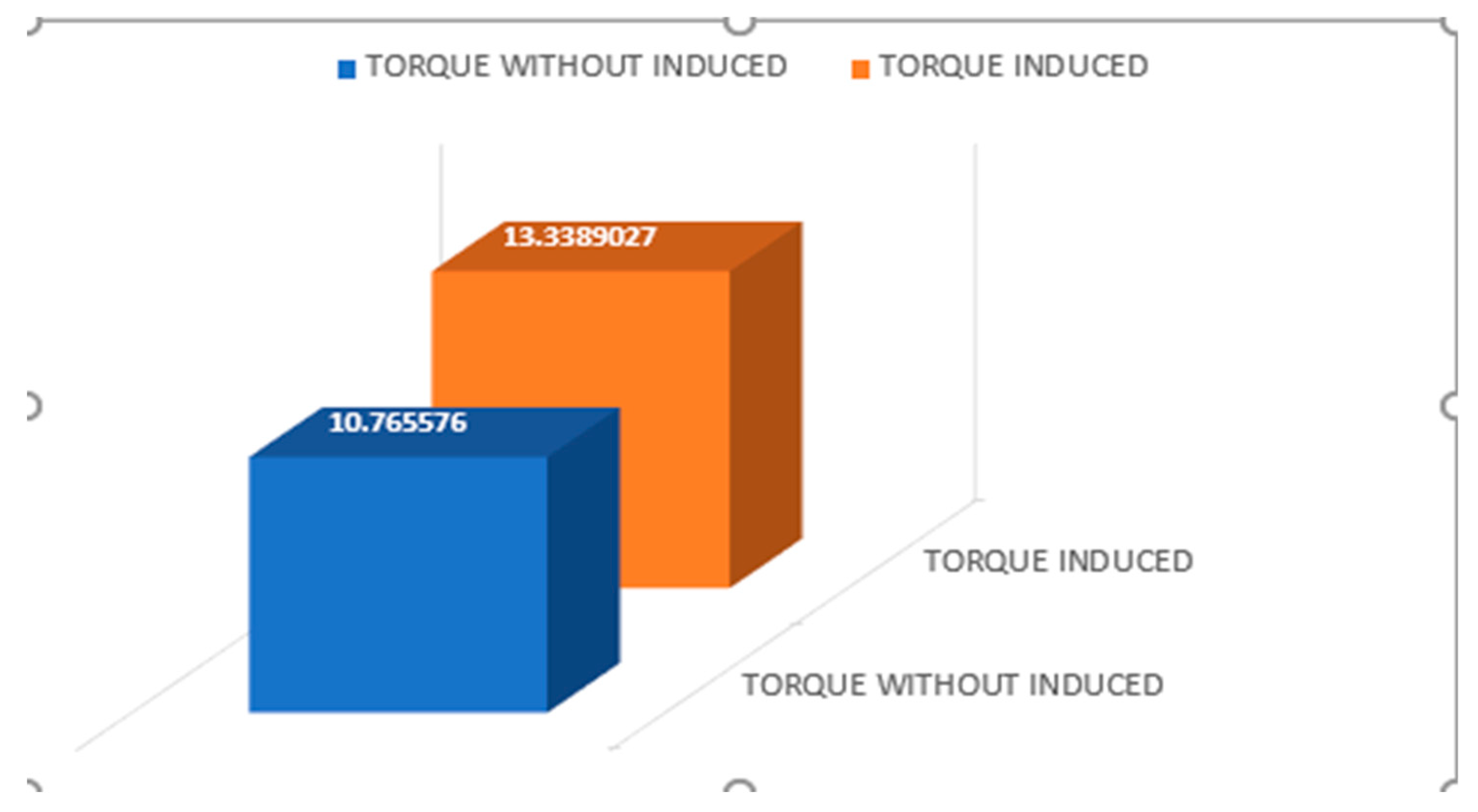
Figure 3.11.
Propeller Torque Using Clark Y (Induced Velocity Vs Without Induced)
The propeller torque increases from 10.765576 to 13.38
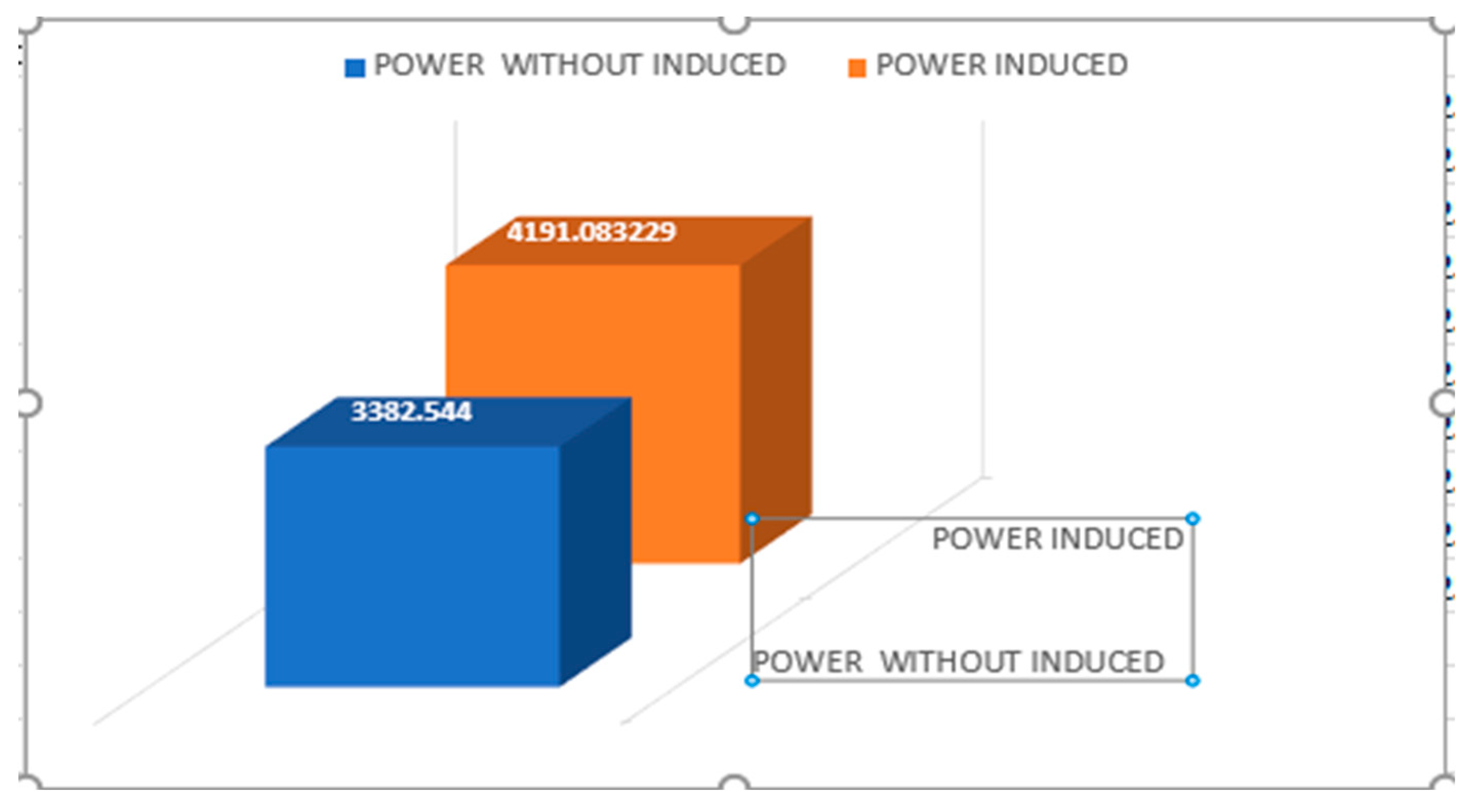
Figure 3.12.
Propeller Power Using Clark Y (Induced Velocity Vs Without Induced).
The propeller power increases from 3382.554Watt to 4191.08 watt
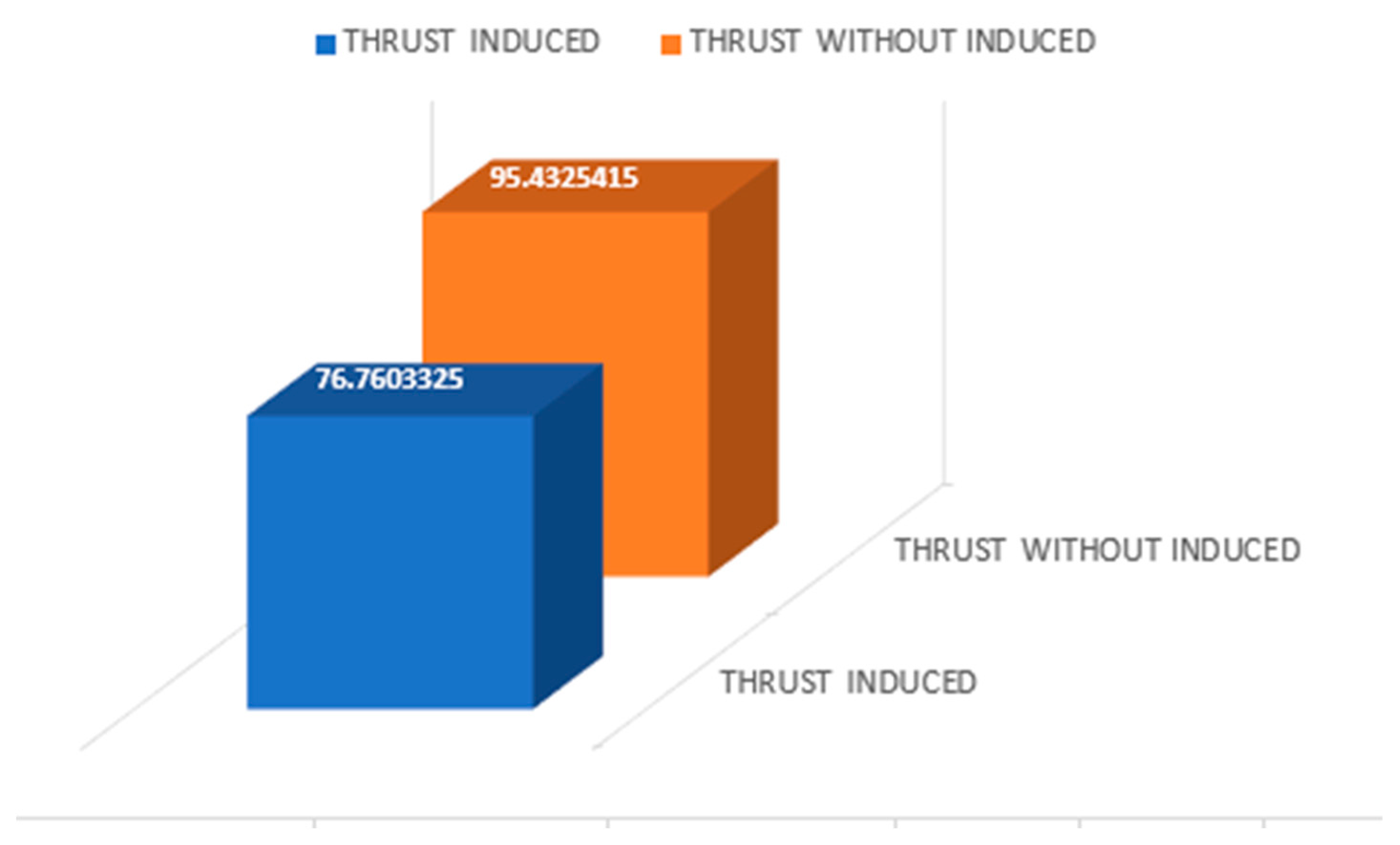
Figure 3.13.
Propeller Thrust Using Clark Y (Induced Velocity Vs Without Induced).
The propeller thrust reduces from 95.4325415 to76.7603325
A MATLAB code has been provided in the Appendix A for those interested in calculating the induced velocity of a propeller.
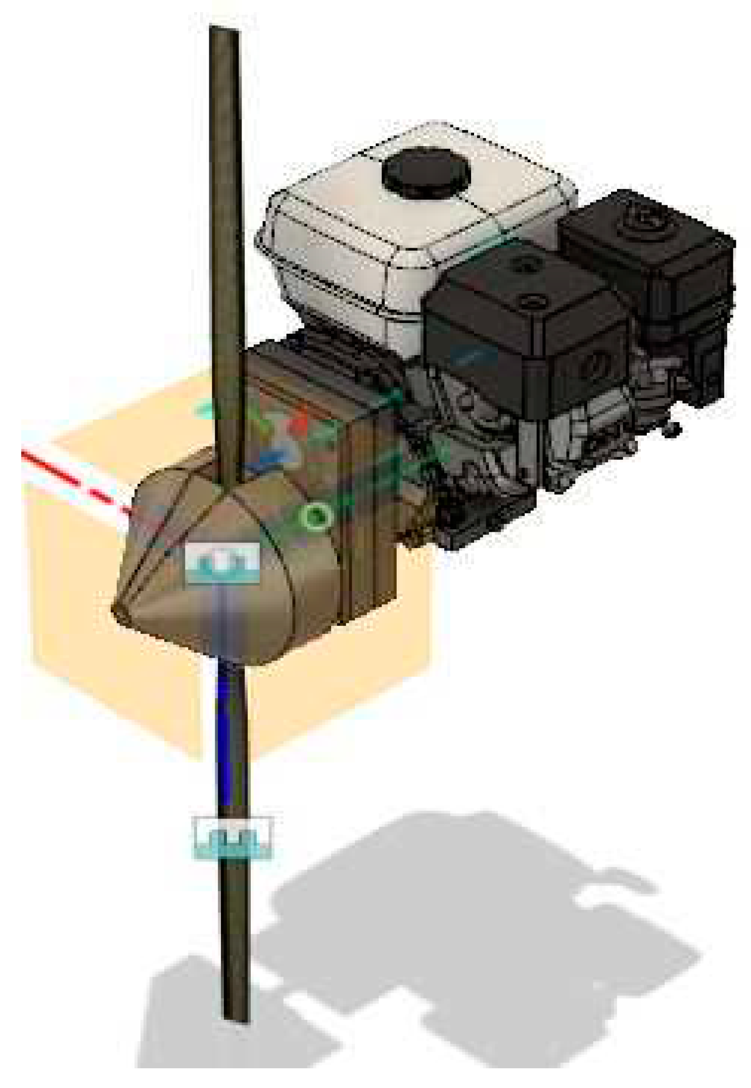
3.3. FULL ENGINE DESIGN
4. CONCLUSION
In this research, a comprehensive exploration of propeller aerodynamics was undertaken with the primary objective of shedding light on the path toward efficient and optimized propeller design. The study delved into the fundamental principles governing propeller performance, unveiling the intricate dynamics of airflow around propeller blades and their remarkable ability to generate thrust, lift, and torque. A comprehensive examination of airfoil profiles, blade geometry, and the core principles of blade element theory formed the foundation of this study. The paper elucidates the step-by-step process followed by designers when crafting an aircraft propeller, beginning with engine parameters and concluding with optimization and final design. The utilization of Blade Element Momentum Theory (BEMT) in this paper provides valuable insights for new designers, facilitating a deeper understanding of the underlying design principles. The knowledge acquired equips propeller designers to tailor their designs with precision, aligning them seamlessly with specific performance goals. It is worth noting that while Excel and QBlade were utilized for simulation in this paper, readers have the option to employ simulation software that suits their needs.
Although a wide array of concepts is covered, it is essential to acknowledge that some topics may not have been explored in extensive detail due to the chosen methods for design and optimization. In such instances, readers are encouraged to draw connections between their specific inquiries and the relevant formulas presented herein. This research endeavor serves as a guiding beacon, offering valuable insights to both propeller enthusiasts and experienced professionals. It not only enriches the understanding of propeller technology but also paves the way for future innovations in propeller engineering.
List of Parameters
| PARAMETERS | MEANING |
| L | Lift (Newton) |
| W | Weight (Newton) |
| T | Thrust (Newton) |
| D | Drag (Newton) |
| AR | Aspect Ratio (Dimensionless) |
| e | Oswald Factor (Dimensionless) |
| Induced Coefficient of Drag (Dimensionless) | |
| Induced Coefficient of Drag (Dimensionless) | |
| Coefficient of Lift (Dimensionless) | |
| Coefficient of Drag (Dimensionless) | |
| Polar Drag (Dimensionless) | |
| Thrust Required (Newton) | |
| Wing Area () | |
| Density ( | |
| (T/W) | Thrust To Weight Ratio (Dimensionless) |
| (W/S) | Wing Loading (Dimensionless) |
| R.O.C | Rate of Climb |
| rpm | Revolution Per Minute |
| Propeller Efficiency (Dimensionless) | |
| Dia | Diameter(m/inch) |
| BHP | Brake Horsepower (kw/Hp) |
| HP | Horsepower (Hp) |
| P | Pressure (psf/N) |
| h | Altitude (m) |
| Constant (6.8 ) | |
| Resultant Velocity (m/s) | |
| Induced Velocity(m/s) | |
| Power Coefficient (Dimensionless) | |
| Differential Induced Velocity (m/s) | |
| r | Blade Chord Length (m) |
| Torque Coefficient (Dimensionless) | |
| Thrust Coefficient (Dimensionless) | |
| J | Advance Ratio (Dimensionless) |
| Number Of Blades (Dimensionless) | |
| n | Revolutions Per Second rps |
| Geometric Pitch Diameter (m) | |
| Q | Propeller Torque (Dimensionless) |
| R | Blade Radius(m) |
| V | Velocity (m/s) |
| Propeller Rotational Speed (m/s) | |
| Rotation Rate (Degree) | |
| Angle Of Attack (Degree) | |
| Geometric Pitch Angle (Degree) | |
| Helix Angle (Dimensionless) | |
| Induced angle of attack |
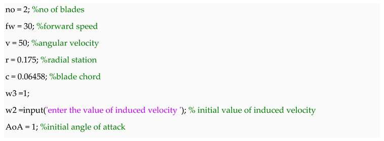
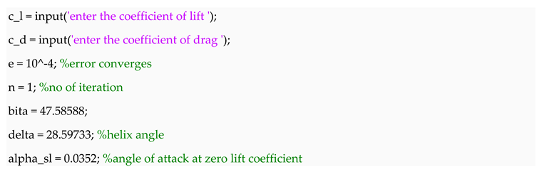
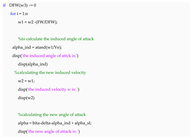
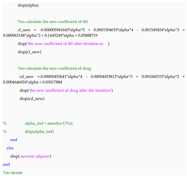
Appendix A. MATLAB Calculation of Induced Velocity
propeller given
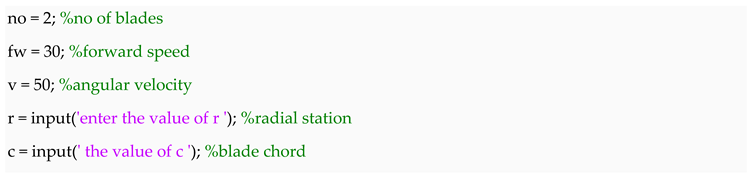
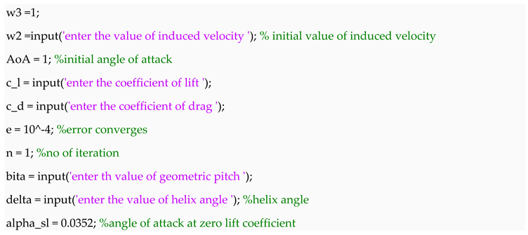
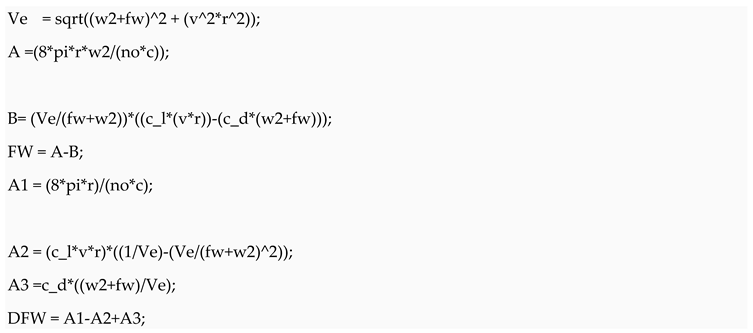
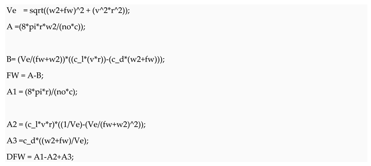
processing
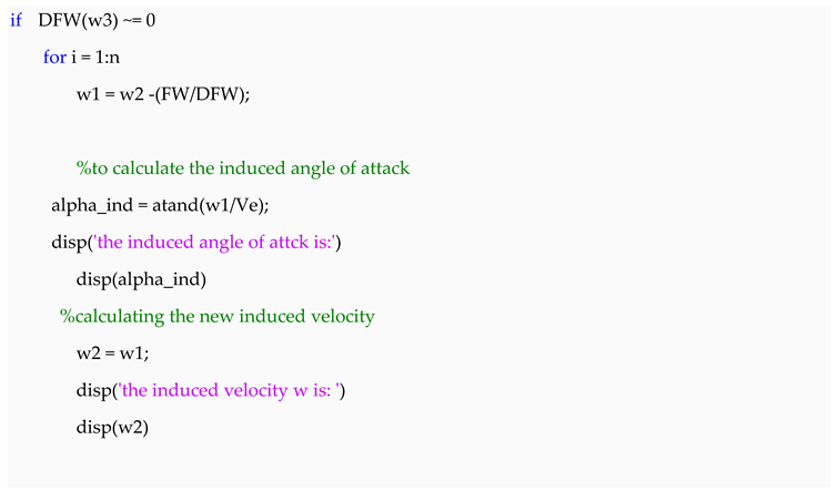
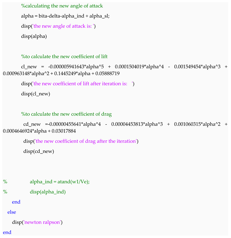
another matlab script file is written for newton Rapson equation of induced velocity, its should be noted that the radial, chord radial, geometric pitch and helix angle must be changed to the section of the blade working on.
propeller given
processing
References
- Alamy. (n.d.). Aeroplane with spinning propellor preparing for takeoff at airshow, England, United Kingdom. Retrieved September 27, 2023, from https://www.alamy.com/stock-photo-aeroplane-with-spinning-propellor-preparing-for-takeoff-at-airshow-59752722.html.
- bing. (n.d.). E63. Retrieved September 30, 2023, from https://sl.bing.net/kHqR4aqMBQy.
- Class, F. (n.d.). building an aerofoil wing.
- DMS. (n.d.). Propeller By the numbers. https://www.dmsonline.us/propellers-by-the-numbers/.
- Document, M. (2000). Propeller Geometry : Terms and Definitions Master Document. August, 1–18.
- Jacobs, E., Ward, K., & Pinkerton, R. (1933). The characteristics of 78 related airfoil sections from tests in the variable-density wind tunnel. National Advisory Committee for Aeronautics, 299–354. http://oai.dtic.mil/oai/oai?verb=getRecord&metadataPrefix=html&identifier=ADA801175.
- Kevadiya, M. (n.d.). diagram of airfoil geometry.
- Pixabay. (n.d.). gray airplane propeller. https://www.pexels.com/photo/gray-airplane-propeller-159430/.
- Public. (2015). Does Max Power RPM Equal Max FE? https://mechanics.stackexchange.com/questions/19712/does-max-power-rpm-equal-max-fexchange.
- Rizzi, A., & Oppelstrup, J. (2021). Introduction to Aircraft Aerodynamic Design. Aircraft Aerodynamic Design with Computational Software, 1–44. [CrossRef]
- Silverstein, A. (1935). Scale effect on Clark Y airfoil characteristics from NACA full-scale wind-tunnel tests. 502, 13. http://ntrs.nasa.gov/search.jsp?R=19930091575&hterms=airfoil+naca+0015+0015&qs=Ntx%3Dmode%2520matchallany%7Cmode%2520matchany%7Cmode%2520matchany%26Ntk%3DAll%7CAll%7CAll%26Ns%3DLoaded-Date%7C1%26N%3D0%26No%3D140%26Ntt%3Dnaca%25200015%7C0015%7Cairfoil.
- Smu.edu. (n.d.). Propellers. https://s2.smu.edu/propulsion/Pages/propeller.htm.
- Snorri Gudmundsson. (2014). General Aviation Aircraft Design : Applied Methods.
- Tim Kramer. (2020). DIFFERENCES BETWEEN 2,3, AND 4 BLADED PROPELLER.
Disclaimer/Publisher’s Note: The statements, opinions and data contained in all publications are solely those of the individual author(s) and contributor(s) and not of MDPI and/or the editor(s). MDPI and/or the editor(s) disclaim responsibility for any injury to people or property resulting from any ideas, methods, instructions or products referred to in the content. |
© 2023 by the authors. Licensee MDPI, Basel, Switzerland. This article is an open access article distributed under the terms and conditions of the Creative Commons Attribution (CC BY) license (http://creativecommons.org/licenses/by/4.0/).
Copyright: This open access article is published under a Creative Commons CC BY 4.0 license, which permit the free download, distribution, and reuse, provided that the author and preprint are cited in any reuse.


