
Submitted:
26 September 2023
Posted:
28 September 2023
You are already at the latest version
Abstract
Recently, Electric Two-Wheelers ETW are changing the face of the global automotive market. This study focused on selecting proper material and mechanical isolation gap to design a protective enclosure for the battery pack of ETW. The integration of the Failure, Modes, Mechanism and Effect Analysis (FMMEA) method is utilized to develop the interface matrix and the severity index of different components of the enclosure. By analyzing different forces from the road conditions, dynamics during turn, acceleration, and deceleration with the enclosure, it becomes a crucial load-bearing element. Employing Finite Element Modeling (FEM), structural strength using materials like AL6061, Q235, C22000, DC 01 and Teflon are assessed under varying static, dynamic and thermal conditions. Modal analysis is conducted to observe the excitation frequencies where the maximum deformation for the metal enclosure is observed beyond 500Hz. AL6061 material that can withstand the stresses and deformations that are under allowable stress limits with negligible deformation is most preferable material based on the results. Minimal of 2.5 mm gap to be provided in case of metal casing and 10mm in case of Teflon is proven.
Keywords:
Battery enclosure
; electric two-wheeler
; structural analysis
; material selection
; failure analysis.
1. Introduction
Electric vehicles (EVs) are the current alternative source of green transportation in the automobile industry. Limiting pollutants is a vital motivating factor for the transition to cleaner and more powerful alternatives from traditional internal combustion engines [1,2], also consumes less energy and has zero emission of tailpipe gases [3]. Additionally, EVs have more advantages in less running cost and maintenance costs over their counterparts. With this, there was a steady rise in the electric vehicle market, especially in Electric Two-wheelers (ETW) and partial growth in Electric Four-Wheelers (EFW). This is due to its vehicle cost, an average cost of an electric four-wheeler E4W with a power range of 74.4 kW to 43 kW is between 30,000 and 47,000 USD [4]. Whereas for ETW, the Prize start at USD 1000 having a range of 0.5 kW to 15 kW with a maximum speed of 45 to 90 Kmph. Based on the statistics there will be a drastic change in sales of E2W in Asian countries like India, Taiwan, Vietnam, Indonesia, etc., [5] Based on 2018 statistics 30 million units are sold and 250 million E2W in stock [6]. The lithium-ion battery is considered more advantageous over other batteries (e.g., lead-acid, NiMH, etc.) due to its compactable mass, resistance to self-discharge, compact design, power density, recycling capabilities [7] and lifespan [8,9] and better rage that revamps the EV market [10]. Despite the advantages of the Lithium-ion combination, safeguarding the battery pack is highly recommended, due to its catastrophic failure conditions. As Lithium-ion batteries are renowned for their advantages as discussed, however the potential of failure can disrupt their functionality. Extensive research [11] highlights various abuses that lead to thermal runaways. It is observed that Mechanical stresses and penetration of the forces that deform the casing as shown in Figure 1, lead to electrolyte leakage of individual cells, causing thermal runaway. The structure of the modules and the other components highly relies on the battery pack enclosure that protects the vital components inside the pack, ensuring reliable operation and safeguarding against mechanical abuse. Hence, the battery enclosure has to ensure the stress isolation from the vehicle that can lead to pack failure. In this work, to enhance the safety of the modules, different materials are studied for structural stability.
The novelty of this study is to conduct static, thermal, transient, and dynamic analysis on the swappable battery pack with an enclosure using different materials based on the literature survey in the next section using ANSYS Workbench. A material that can withstand high levels of stress and less deformation is finally proposed. Design Failure Modes, Mechanism and Effects Analysis (DFMMEA) is utilised in this work, which is the most important tool that prevents failure through detailed analysis [12]. The detailed approach is explained by Ganesan, S., et al., 2005 [13]. Two key tools are explored with DFMMEA that provide the structures approach for understanding the system boundaries, interaction, and causes of failure. Predicting the failure of a lithium-ion cell is challenging: external thermal loads, mechanical abuse, etc., have an immediate effect on thermal runaway [14].
1.1. Failure, Modes, Mechanisms and Effects Analysis (FMMEA)
Design Failure Modes, Mechanisms and Effects Analysis (DFMMEA) is utilised in this work[12]. The detailed approach is explained by Ganesan, S., et al., 2005 [13]. Two key tools are explored that provide the structural approach to understanding the system boundaries, interaction, and failure. Below are the tools utilised to analyse the interaction and associated failure through boundary diagram and interaction matrix.
- Boundary diagram: It is a visual representation that defines the interface between different components within the battery enclosure. The interconnected elements are displayed in Figure 2. This boundary diagram helps to identify the inputs, outputs and interaction of the structural chassis and environment, ensuring the potential failure modes.
- Interface matrix: This is also known as the input-output matrix, providing clear highlights through the boundary diagram. It systematically maps the failure at their interfaces and evaluates to assess how failures in one part of the system propagate to another. Table 1 presents different interaction matrices of the battery pack concerning the battery enclosure.
2. Literature Review
Material selection plays a prominent role in battery structural stability. Two vital considerations of battery enclosure design are to achieve less weight and better structural stability [15]. A literature review is divided into two sections. In the first section the importance of static and dynamic analysis for the material of the enclosure is reviewed In the second section different materials used for the analysis are reviewed pointing to the objectives of the work. Based on the review the authors discussed that fabricating battery cases using aluminium or alloys of aluminium is preferable for better weight compositions of the battery pack. Studies were conducted to optimise the enclosure model through structural analyses using renewed software like Ansys workbench to improve the safety of electric vehicles. Yang, N., 2019, did a static and dynamics analysis using FEA and optimising the design [16], Wang, G et al., 2021, explored the failure modes of the battery with different axial, compression, and impact loads [17]. Furthermore, the position of the battery pack is an important consideration in vehicle design [18]. The authors suggest that placing the battery pack at the vehicle's centre near the Center of Gravity (CG) can reduce the vulnerability during impact loads [19]. The force transfer rate while accelerating, decelerating and taking a turn will prominently depend on the battery's position within the vehicle. The static and dynamic analysis provides the structural stability of the system and also gives the failure modes that are helpful in optimised model and material selection. Polymers-based materials were studied to minimise casing weight and design which are commercially used. Maguire et al., 2017, designed a battery system casing using High-Density Polyethylene (HDPE) material as a substitute for the metal casing to reduce the weight [20]. Although it achieved reduced weight compared with steel casing, it became more sensitive to fire exposure, when the casing was tested without using an aluminum sheet, used as shielding material for the casing. Alternative fabrication processes such as additive manufacturing can help design intricate shapes with required properties in addition to mass reduction. Reinforced aluminum material was used and analysed from the existing guidelines [21]. Choi et al., 2013, developed a battery case made with fibrous composite material because of its price effectivity and weight reduction [22]. The carbon content in these polymer materials added strength to the design. However, during the simulation, the stresses on the design were exceeded, regarding the design as a failure.
Aluminium-based materials were used after steel and other metal alloys in modelling the casing as the design should be less deformed and light in weight [23]. A method of changing the material of battery casing parts from mild steel sheet to aluminium alloy steel sheet is proposed, and the selection of the right material using the material parameters was investigated [24]. Air-cooled arrangement type of battery pack casing is designed for the enclosure using the aluminium base plate, polycarbonates, FR4 inner walls, and aluminium sheets for the lid. The casing met all the requirements as it could secure the modules during sudden accelerations or decelerations from crash scenarios [25]. Zhang, Y. et al., 2020, designed an enclosure using materials of steel, aluminium, copper, and carbon nanotubes of specific grades to compare the maximum equivalent stresses and resonance frequency under bumps, turning, braking, and stationary conditions [26]. Wang, Chen, and Zhao, 2016, also conducted this study using steel structures under vertical impact, turning, acceleration, and braking conditions [15]. Yang, N. et al., 2019, used a steel-material enclosure to analyse the battery casing under the combinations of braking, turning, static loading, and modal analysis, the bottom cover and sidewalls were focused on the design development and achieved their expected static performances [16]. Yang et al., 2019, analysed the static and vibration aspects of an enclosure for an EV, tests performed in the static study were road bumping, emergency braking, and sharp turning [16]. Naresh et al., 2020, applied the air-cooling method of cooling arrangement for the battery casing of the electric vehicle that has a large surface area and good thermal conductivity, results showed that Aluminum alloy (Al 6061) material was a good choice for designing casing components as it showed good thermal response among the tested materials simulated in their work [27]. Wang, J. et al., 2016, explained the importance of modal analysis for a battery box [15]. Shui, L., et al., 2018, performed optimisation techniques for an aluminium alloy battery pack enclosure, which was chosen for its lightweight and structural strength. When loads are inserted, the impact load produced is the amount of static charge extracted from the battery pack [28]. Hartmann, et al., 2013, explained the importance of natural frequencies of the battery cover and vehicle frequency [29]. Zhu et al., 2020 tested the behaviour of battery modules using aluminium as cooling plates and steel coverings as a part of mechanical and crashworthiness studies [30] Moreover, to identify the safety features of the ETW it is important to understand the mechanical features that can resist the deformation and vibration loads while in operation [17]. A gap lies in understanding which material will be appropriate to minimise the mechanical abuse on the cells. The literature survey highlighted the significant role of material selection like AL6061, Q235, DC01, C22000, and Teflon in ensuring the structural stability of battery pack enclosures. The objective of achieving reduced weight while maintaining structural stability was emphasised. Static and dynamic analysis using validated software like Ansys was identified as a valuable tool for optimising the enclosure design and enhancing ETW safety.
3. Methodology
The review emphasises the importance of analysing mechanical features to withstand deformation and vibration loads to identify hazards [26]. Based on the findings, this research aims to conduct static, modal and dynamic analysis using ANSYS Workbench, select suitable stability, explore failure modes due to mechanical abuse, and identify features to resist deformation under different materials. The three phases of mechanical failure are illustrated in Figure 3. In the subsequent sections of this paper, we will discuss how a battery pack is developed through failure isolation and different boundary considerations to conduct analysis with different materials. Provided results help the material optimisation based on the stress and displacement nephogram under different conditions [16].
3.1. Forces on the Enclosure
The primary function of the methodology is to identify forces in the battery compartment. The failure rate of the pack always depends on the mechanical behaviour of the enclosure that can withstand the forces [23], It is crucial to analyse the forces acting upon it and the forces exerted during different operations of the vehicle. It is also crucial that the battery pack enclosure must be light in weight and robust in design, so that can withstand the impact loads during collision and while operating [18,24]. The specific challenges are to withstand the forces and protect the individual cells inside the pack. Different boundary conditions, commercial models, standards, failure mitigation, etc., are considered while designing the pack. The developed battery pack must be scalable, cost-effective and fulfil the customer needs with utmost safety [26,31,32]. DFMMEA method in section 2, is used to break down the failure criteria of individual components in the pack and their associated severity.
3.1.1. Isolation of Forces on the Enclosure
The major structural difference between the IC engine to ETW is replacing the fuel tank, engine, transmission system and exhaust system of the convection IC two-wheeler with an electric motor and battery component without affecting the vehicle's performance. In a conventional vehicle, the engine is fitted inside the chassis cage, the rear swing arm is pivoted to provide suspension movement, and the associated mechanism protects the components from different forces [33]. Different types of frame models are used based on different varying parameters like the cost of the vehicle, uniformity of weight distribution, power, torque factors and other complexities. Apart from design and other complexities vehicle frames will absorb the shocks developed from the road profile, protecting the vital components inside the cage [34]. Based on the consideration of similar forces exerted on the engine a double cradle chassis frame is considered in this work. While designing a pack the forces to be isolated during operation are self-weight, acceleration, deceleration, taking a turn and impulse reaction due to a crash. To conduct the Finite Element Analysis (FEA), the forces considered are:
- Self-weight of the pack fixed within the vehicle frame, forming the rigid support. For example, in this work, we considered two 8P10S configurations having 160 cells based on the single cell configuration of 18650 each cell is 0.045kg, which comes to 7.2 Kg uniform weight acting on the base plate of the enclosure.
- Bump forces generated from the improper road profile to the contact point of the tire. The generated forces are damped by mono-shock suspension at the rear and a telescopic suspension system at the front. A partial number of vibrations are transferred from the suspension to the chassis in turn to the battery enclosure.
- Forces while taking turns exert centrifugal lateral forces on the side walls of the pack which is due to the centrifugal movement of the ETW. This inertial load pushes the right portion of the pack to the left and vice versa.
- Deceleration and acceleration force due to sudden braking or acceleration generates longitudinal weight transfer, pushing the components in the battery in the forward or backwards direction, forcing the battery pack towards the restraining bars. Ploy carbon materials (HL6157) [35] sheets for restraining bars in this work have good fracture toughness and can absorb deformation load. These restraining bars hold the modules secure during downward forces.
- Impulse force or crushing force developed due to a sudden crash exerts an enormous number of forces transferring to the module of the pack and to the individual cells which can result in premature failure. The exerted load on the pack is unpredictable and can lose mechanical stability, resulting in thermal runaway [36,37].
Based on the discussion the crash force during an accident is critical and severe compared to other forces. Accordingly, crash configurations are derived from the ISO13232, in which most modes of crash observed are (a) Front impacting the front or side of a passenger car, (b) Front impacting the front or side of a truck, and (c) Impacting ground are the most pervasive two-wheeler collision scenarios. With respect to that in Figure 4 frontal area and side impact are considered as the most General Area of Damage (GAD) in an accident, which is considered for boundary conditions to apply force in analysis.
3.2. Mechanical Failure Mitigation
Failure of the battery can be due to mechanical or structural failure, physical, mechanical, chemical, short circuit, power fade, material degradation and thermal abuse that leads to explosion [38]. A reliable battery pack model avoids thermal runaway, vibration isolation and crashworthiness safety to individual cells and even modular levels [39]. Utilising the best material to improve safety and reduce the material cost without compromising on the performance and stability of the battery pack is prominent [11]. Improper internal fittings in the battery enclosure, coupled with vehicular chassis vibration, can lead to pack failure. While designing the battery enclosure and pack one must adhere to the battery standards [40] outlined in Table 2. The structural design must incorporate fixtures capable of effectively isolating vibration, ensuring the integrity of the battery which was followed in this work while designing the pack.
Battery packing and module assembly is the challenging part which holds the entire battery intact and must withstand high internal forces as discussed in the previous sections. To have more indite into the design we have developed an experimental model of the battery pack with 320 welding points using the spot welding technique with nickel stripe which is a commonly used method as shown in Figure 5 [41,42].
Cells are horizontally packed in 10P8S configuration, this configuration allows to generate output power of 3 kW and 27 Nm of torque [43]. The generated output can run a Brushless Direct Current (BLDC) motor with a capacity of 3 kW, corresponding to 72 V, 19.2 Ah. A maximum range of 100 to 120 kmph is estimated, detailed specification is listed in Table 3.
4. Design Overview
Based on the criteria and standards an overview is presented in this section while developing the model for analysis. The primary function of the battery pack design, it must comply with the standards as mentioned in Table 1, its most significant function is to hold the modules securely when subjected to different types of forces while operating a vehicle. More specifically, the pack is positioned in the vehicle as a swappable mode, which makes it possible to remove or replace the battery in 10 seconds. A rectangular battery pack is considered to have good packing efficiency and volumetric efficiency. Roland Uerlich et. al. 2019, in their experimental study comparing the space occupancy and volumetric efficiency on rectangular, hexagonal, and trapezoidal geometric module rectangular structure of the pack has 100% volumetric efficiency and 81.79% of space occupancy with 675 cells [36], for which rectangular modules are selected for the analysis. The enclosure must also compile with a high level of packing efficiency and carry all the necessary electronics intact within the structural body.
4.1. Packing and Volumetirc Efficiency
Battery pack consists of different modules connected to the Battery Management System (BMS). Packing efficiency, volumetric efficiency and spacing rate between the batteries, rectangular compact enclosure model is developed by reducing the space rate as shown in the Figure 5 and Figure 6. Volumetric Efficiency (Ve) is calculated using.
For identifying the space occupancy rate of the pack, and for having good axial strength and flexibility Lithium-ion 18650 cylindrical batteries are considered for pack design. Space Occupancy Rate (SOR) was calculated using Equation (2), associated values are in Table 4.
Based on the study by Bai, Q., 2023 it is suggested that the thickness between the adjacent cells is to be maintained at 2 cm and the adjacent modules with 10 mm thickness [42]. Due to the provided spaces as per the literature, the achieved volumetric efficiency is 63% and 37% occupancy rate. The developed CAD model battery pack is shown in the Figure 6.
5. Material Selection
In the literature survey, various materials have been identified and considered for enclosure material to conduct static and dynamic analysis in ANSYS. The five most prominently used materials were considered as enclosure materials. For thermal and vibration insulation polyurethane impact resistance materials are used as vibration insulators and polycarbonate sheets between the modules that are effective between -35°C to 75°C. Material data for each component is presented in Table 5, encompassing relevant mechanical properties.
6. Static Analysis
Static analysis helps to understand the enclosure's ability to withstand mechanical stresses, while dynamic analysis assesses the response to varying loads. Under static conditions, the self-weight of the battery pack is acting on the base plate. For analytical calculation, the maximum moment under uniform conditions where ‘f’ is the force acting on the base plate per unit length [43].
With this the maximum stress developed in the material where ‘w’ width of the bottom plate and ‘h’ is thickness of the plate maximum deflection is calculated as
The result of the thickness calculation is shown in Figure 7. Similarly, the maximum deflection range of each material is calculated using Equation (4). Based on the analytical calculations the optimal thickness of the casing is maintained to 3 mm and 4 mm, considering 20 g force loading conditions used for designing and analysing the casing.
7. Dynamic, Thermal and Modal analysis
7.1. Dynamic boundary conditions
Modal analysis plays a pivotal role in ensuring the durability and reliability of battery packs. By revealing vibrational behaviour and resonance tendencies, it empowers engineers to design and optimise structures that can withstand real-world dynamic conditions. Modal analysis is conducted for different materials to explore the possibilities of resonance that can prevent failure and enhance the overall performance and longevity of the battery. To replicate the practical scenarios, the base plate of the casing is constrained, facilitating the accurate representation of the vibrational response and guiding the refinement of the vibrational isolation. The effective mass-to-weight ratio, an integral part of the Participation Factor PF, quantifies mode frequencies. Higher ratios signify modes with more impact on the system.
Extending the analysis, a transient study was conducted on the enclosure by dropping a 42 kg solid block from a height of 10 m. The same materials based on the literature were applied to explore the effects of impact dynamics. Additionally, this analysis will emulate how the enclosure responds to sudden impacts. Various deformation patterns and stress distributions unveil how the material interacts with kinetic energy. Applied boundary conditions were acceleration due to gravity is applied on the drop box and the base plate of the enclosure is constrained to have a direct impact load on the upper case of the enclosure.
Considering the vehicle turning with a radius (R) and velocity (V), lateral loads were applied on the enclosure sidewalls by constraining the base plate. The 2 g load of centrifugal force (CF) was calculated as 140 N, 500 N and 1000 N. The relation between CF and CA is utilised to calculate the mentioned forces. These dynamic parameters were computed to assess the enclosure response while taking the turn subjected to lateral loads.
7.2. Thermal boundary conditions
To assess the thermal capabilities of the battery pack enclosure material, a steady-state thermal analysis was conducted in ANSYS Workbench Fluent. The analysis considered the extreme temperature conditions of 450 C. With these ambient conditions, the temperature rise inside the enclosure can reach more and the importance of material is studied in this work. Based on the HPPC test data of the EC model of the lithium-ion battery, a temperature of 40-42°C is observed at a 2 C discharge rate. At these conditions, the maximum temperature observed at the cell's core was 40°C for analysis of the battery pack temperature in the same. Temperature boundary conditions of the enclosure are divided into vertical and horizontal surfaces for which the convective heat transfer coefficient (h) is calculated from the Church-Chill-Chu correlation in Equation (5).
8. Results and Discussions
Based on the developed CAD model, the comprehensive analysis provides crucial insight into the weight variation plotted in Figure 9 with different thicknesses and materials. The graph presents that AL6061 is the only lightweight material close to Teflon, which is commonly used, that can maintain the weight ratio and structural stability.
8.1. Structural analysis
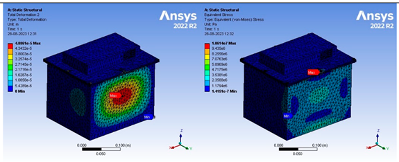
Under 140 N load (2 g loading conditions), all selected materials conform to be under the allowable range except for Teflon, maximum stress, and deformations deformation of 0.3 mm and 1mm is observed under the maximum stress value of 2.5 MPa and 1.8 MPa at 500 N and 1000 N forces, in turn transferring the forces through the polyurethane insulators to the battery pack that can lead to mechanical abuse — the associated contours of maximum stresses and maximum deformation Table 6.
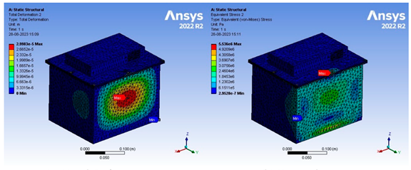
A comprehensive static analysis was conducted on the battery enclosure, holding significant importance in mitigating the abuse of the battery pack as presented in Table 1 based on the FMMEA approach. Performed static analysis involving self-weight, turning force of 140 N, 500 N and 1000 N applied on the side walls with different materials provided valuable insight. The stress contours for 140 N force of 3 mm thickness are presented in Table 7. The remaining forces are plotted in the graph in Figure 10, offering critical information regarding the material structural integrity. This data confirms the sustainability of the AL6061 and has satisfactory mechanical performance, ensuring the required strength to withstand static conditions. Furthermore, this analysis establishes a rationale for subsequent dynamic and thermal investigation, enhancing the overall assessment process.
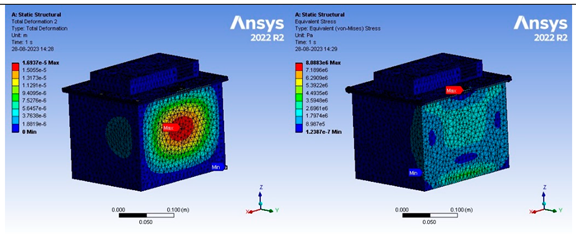
Under 500 N and 1000 N force while taking the turn as mentioned earlier on the enclosure side walls, selected materials demonstrated developed maximum stresses are within the allowable limits, ensuring a Factor of Safety more than 5. At 4 mm thickness range, the consistent stress patterns are observed in comparison to 4 mm with 3 mm thickness as illustrated in Figure 10 and Figure 11. Highlights the inadequacy that maximum developed stress is 4 Mpa at 500 N force and 8.5 Mpa at 1000 N force, where as its yield stress is 20.68 Mpa, reaching almost 40% to the designed stress which can fail at higher impact loads.
The deformation graph reveals significant insights, as for all materials, maximum deformations under 140 N, 500 N, and 1000 N forces remains within the acceptable thresholds. However, Teflon exabits deviations, with deformations reaching 4 mm and 8 mm for 4 mm thickness under these load conditions. This holds particular significance considering 4.5 mm gap between the pack and the casing for thermal and vibration isolation. AL6061 emerges as a best-chosen material considering weight, stress and deformation performance align well within the desired range for enclosure materials. Further investigation relating to the vibrational capabilities and thermal analysis is done for understanding the material behavior.
8.2. Modal Analysis
Behaviour of metal enclsoure material are done as teflon is proved to be improper for battery enclosure based on the static and dynamic analysis. Resonance assement indicates the selected material falls within non-resonating zone: 0–7 Hz for the suspension system and unsprang mass, 7–20 Hz for the vehicle powertrain, and 20–40 Hz for the chassis. Material suitability is prefered by resonance occuring more than 500 Hz for the first three modes as displayed in Table 8, confirming the robustness and safety of the pack.
8.3. Thermal Analysis
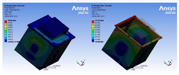
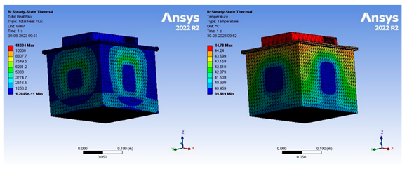
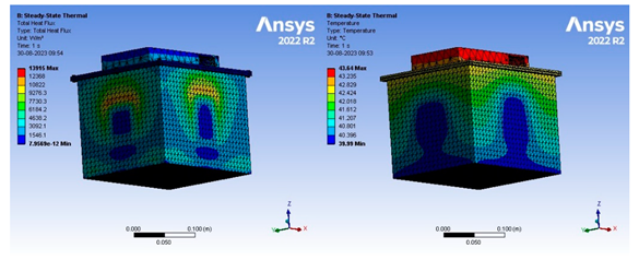
With the provided positive outcomes through static and dynamic analysis of different materials. Thermal analysis focused on assessing the materials ability to withstand high temperature, that is critical for battery pack. Thermal behaviour of different materials is presented in the Table 9. The results affirmed AI6061 thermal stability [27], reinforcing its suitability as the preferred material, ensuring safety, and enhancing the performance in varying temperature environment. As AI6061 is the good conductor of heat thermal insulated materials like ceramics or polymers may be employed for enhanced thermal management. In this analysis polyethylene insulators are utilized as shown in the Figure 9, that exabits good thermal insulating properties, reducing the heat transfer from the enclosure. Additionally, this material can effectively absorb and dissipates the vibration, preventing excessive mechanical stresses on the modules.
8.4. Transient Analysis
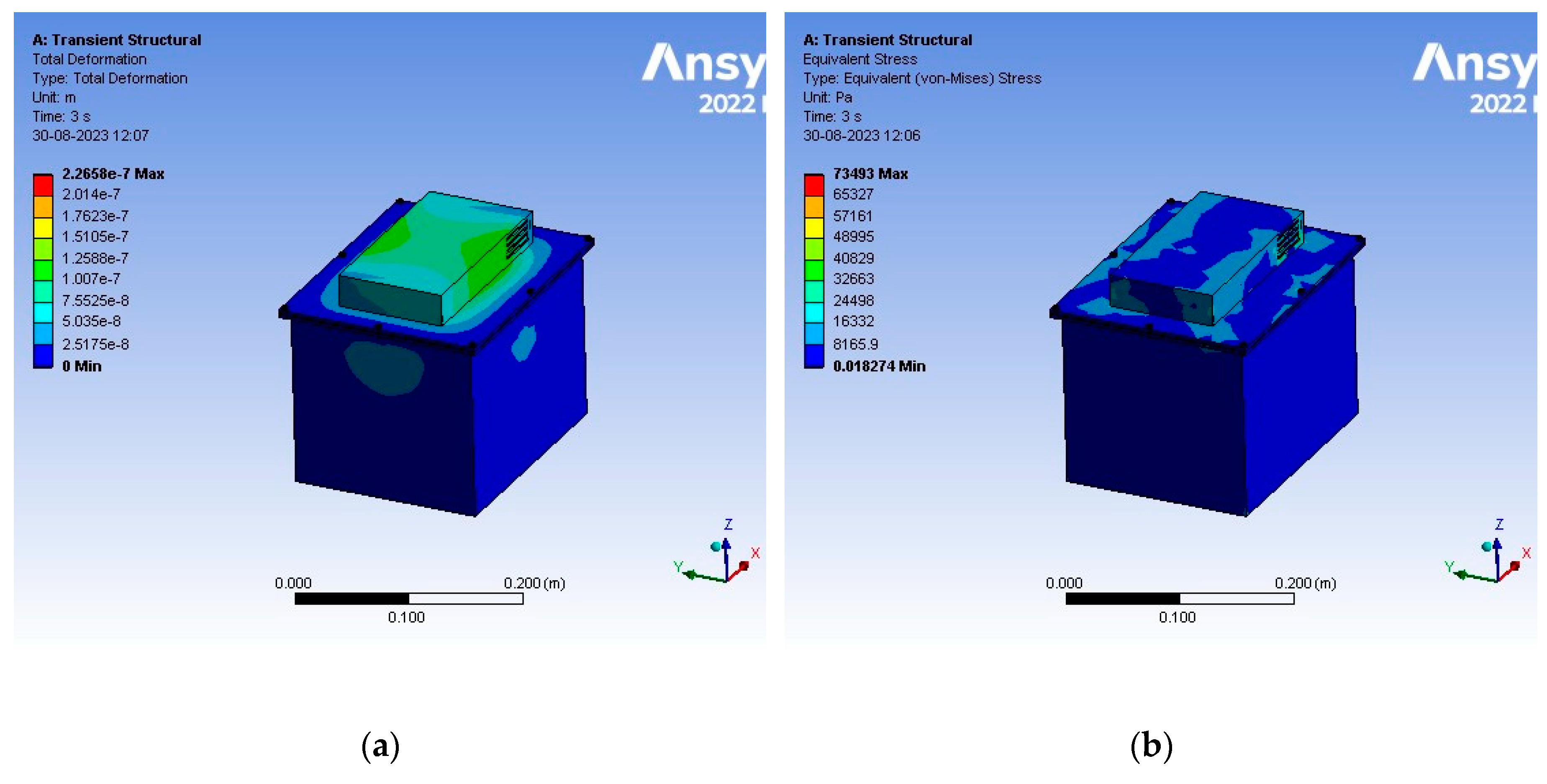
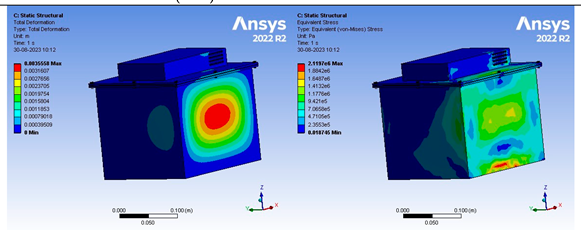
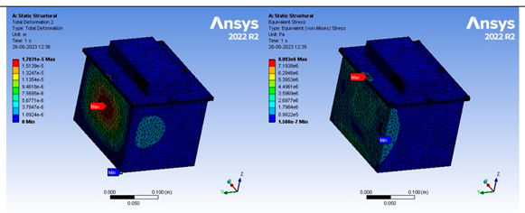
Through the dynamic, static and thermal analysis, AL6061 emerges to be prefereable material. Minimal variances in defromation and stresses, are within the thershold zone. As per the electric vehicle concern weight is the important factor AL6061 is ideal due to its weight advantages and less thermal transfer to the pack. To investigate further, transient analysis subjected to AL6061 is performed with 42 kg weight from 10 m height, which is 4 times the weight of the battery pack. Countors of maximum stresses and deformation are illustrated in the Figure 11, confirms the strucutral integrity of the upper case under impact conditions.
Figure 11.
(a) Maximum deformation of 6061 under drop test; (b) Maximum Stress of 6061 under drop test.
Figure 11.
(a) Maximum deformation of 6061 under drop test; (b) Maximum Stress of 6061 under drop test.
9. Conclusion
In the rapidly evolving landscape of EV’s, the selection of appropriate materials for enclosure has emerged as a vital consideration. Based on the studied DFMMEA model in order to improve the safety and performance. The comprehensive analysis presented in literature survey signifies there is a need to determine the structural integrity under static and dynamic conditions using different materials are made.
The exploration of failure parameters and safety considerations highlights the critical role that the enclosure ensures the overall reliability of the ETW. DFMMEA methodology is utilized to elucidate the complex interrelation matrix of forces and mechanical factors that guided in design and development of battery enclosure. The significance of force isolation and mechanical failure mitigation strategies cannot be overstated and the importance of enclosure design is identified, as they provide the foundation upon which the entire pack is built on.
By integrating insights from the literature review, this study has explored into various materials that have been utilized, encompassing a range of mechanical, thermal, and structural attributes. Among these, AL6061 has emerged as a compelling choice due to its notable balance between weight and structural performance. Despite exhibiting slightly higher deformation as presented in Table 7, Figure 10 and Figure 11 than other materials that is within the designated factor of safety, assuring its relability under operational conditions.
Crucially, AL6061 exabits good thermal and vibrational capabilities compared to alternative materials. For an instance as the battery pack temperature reaches to 40oC with the ambient temperature of 45°C, the inherent thermal properties of AL6061 facilitate steady state temperature of 43°C. This thermal advantages not only ensures the optimal battery performance but also contributes to overall efficiency and longevity. In contrast, materials such as Teflon, which is commonly used for enclosure, demonstrates limitations in terms structural stability, dynamic stability, and thermal capabilities. If a metal casing is used a gap of 2-2.5 mm has to be provided for clearance, whereas in case of Teflon (PTFC) 10 mm gap is to be provided to safeguard the pack and mitigate the failures. Further investigation is required to identify the precise location of the battery pack within the chassis and identifying different locations based on the crash analysis, addressing potential challenges related to structural and thermal management.
Author Contributions
Conceptualization, methodology, writing—original draft preparation, . R,K,C., P.R.P., P.R.K., D.T., J.T. and T.S.; resources, R,K,C., P.R.P., P.R.K., T.S., J.T. and D.T.; language editing T.S., D.T.; supervision R.K.C. P.R.K. and J.T.; formal analysis, R.K.C., P.R.P., P.R.K., D.T., T.S. and J.T.; writing—review and editing, R.K.C., P.R.K., P.R.P. and J.T.; visualization P.R.P., P.R.K., D.T. and T.S. All authors have read and agreed to the published version of the manuscript.
Funding
This research received no external funding.
Data Availability Statement
Data available on request.
Conflicts of Interest
The authors declare that they have no known competing financial interest or personal relationships that could have appeared to influence the work reported in this paper.
References
- Q. Dai, J. C. Kelly, L. Gaines, and M. Wang, “Life cycle analysis of lithium-ion batteries for automotive applications,” Batteries, vol. 5, no. 2, 2019. [CrossRef]
- V. Ruiz, A. Pfrang, A. Kriston, N. Omar, P. Van den Bossche, and L. Boon-Brett, “A review of international abuse testing standards and regulations for lithium ion batteries in electric and hybrid electric vehicles,” Renewable and Sustainable Energy Reviews, vol. 81. 2018. [CrossRef]
- M. V. Faria, P. C. Baptista, and T. L. Farias, “Electric vehicle parking in European and American context: Economic, energy and environmental analysis,” Transp Res Part A Policy Pract, vol. 64, 2014. [CrossRef]
- S. Z. Rajper and J. Albrecht, “Prospects of electric vehicles in the developing countries: A literature review,” Sustainability (Switzerland), vol. 12, no. 5, 2020. [CrossRef]
- R. T. Doucette and M. D. McCulloch, “Modeling the CO2 emissions from battery electric vehicles given the power generation mixes of different countries,” Energy Policy, vol. 39, no. 2, 2011. [CrossRef]
- M. Weiss, P. Dekker, A. Moro, H. Scholz, and M. K. Patel, “On the electrification of road transportation - A review of the environmental, economic, and social performance of electric two-wheelers,” Transp Res D Transp Environ, vol. 41, 2015. [CrossRef]
- Velázquez-Martínez, J. Valio, A. Santasalo-Aarnio, M. Reuter, and R. Serna-Guerrero, “A critical review of lithium-ion battery recycling processes from a circular economy perspective,” Batteries, vol. 5, no. 4. 2019. [CrossRef]
- J. P. Aditya and M. Ferdowsi, “Comparison of NiMH and Li-ion batteries in automotive applications,” in 2008 IEEE Vehicle Power and Propulsion Conference, VPPC 2008, 2008. [CrossRef]
- A. Brogi et al., “Survey High-Performance Modelling and Simulation for Selected Results of the COST Action IC1406 cHiPSet,” Future Generation Computer Systems, vol. 29, no. 1, 2018.
- H. Löbberding et al., “From cell to battery system in BEVs: Analysis of system packing efficiency and cell types,” World Electric Vehicle Journal, vol. 11, no. 4, 2020. [CrossRef]
- Kaliaperumal, M., Dharanendrakumar, M. S., Prasanna, S., Abhishek, K. V., Chidambaram, R. K., Adams, S.,... & Reddy, M. V. (2021). Cause and mitigation of lithium-ion battery failure—A review. Materials, 14(19), 5676.C. Carlson, G. Sarakakis, D. J. Groebel, and A. Mettas, “Best practices for effective reliability program plans,” in Proceedings - Annual Reliability and Maintainability Symposium, 2010. [CrossRef]
- S. Ganesan, V. Eveloy, D. Das, and M. Pecht, “Identification and utilization of failure mechanisms to enhance FMEA and FMECA,” in Proceedings of the IEEE workshop on accelerated stress testing & reliability (ASTR), Austin, Texas, 2005.
- M. Held and R. Brönnimann, “Safe cell, safe battery? Battery fire investigation using FMEA, FTA and practical experiments,” Microelectronics Reliability, vol. 64, 2016. [CrossRef]
- L. Wang, X. K. Chen, and Q. H. Zhao, “Muti-objective topology optimization of an electric vehicle’s traction battery enclosure,” in Energy Procedia, 2016. [CrossRef]
- N. Yang, R. Fang, H. Li, and H. Xie, “Dynamic and static analysis of the battery box structure of an electric vehicle,” in IOP Conference Series: Materials Science and Engineering, 2019. [CrossRef]
- G. Wang, S. Zhang, M. Li, J. Wu, B. Wang, and H. Song, “Deformation and failure properties of high-ni lithium-ion battery under axial loads,” Materials, vol. 14, no. 24, 2021. [CrossRef]
- S. Arora, W. Shen, and A. Kapoor, “Review of mechanical design and strategic placement technique of a robust battery pack for electric vehicles,” Renewable and Sustainable Energy Reviews, vol. 60. 2016. [CrossRef]
- S. Arora, A. Kapoor, and W. Shen, “Application of robust design methodology to battery packs for electric vehicles: Identification of critical technical requirements for modular architecture,” Batteries, vol. 4, no. 3, 2018. [CrossRef]
- P. Maguire, H. Baek, S. Liptak, O. Lomax, R. Palma, and Y. Zhang, “Thermoplastic Enclosure for a High Voltage Battery System,” in SAE Technical Papers, 2017. [CrossRef]
- S. K. Pal, S. Singh, H. Singh, M. L. Le Phung, S. Yooyen, and S. Sleesongsom, “Intelligent design optimization of battery pack enclosure for electric vehicle by considering cold-spraying as an additive manufacturing technology,” Energy Storage, vol. 2, no. 3, 2020. [CrossRef]
- C. H. Choi, J. M. Cho, Y. Kil, and Y. Yoon, “Development of polymer composite battery pack case for an electric vehicle,” in SAE Technical Papers, 2013. [CrossRef]
- N. Bao and R. Zhao, “Design optimization of battery holder for electric vehicle,” in 2018 6th International Conference on Mechanical, Automotive and Materials Engineering, CMAME 2018, 2018. [CrossRef]
- Q.-S. Chen, H. Zhao, L.-X. Kong, and K.-W. Chen, “Research on Battery Box Lightweight Based on Material Replacement,” 2017. [CrossRef]
- H. Merrow, “Design and analysis of a battery pack enclosure for Formula SAE,” Massachusetts institute of Technology, Massachusetts, 2017.
- Y. Zhang et al., “Multi-objective optimization of lithium-ion battery pack casing for electric vehicles: Key role of materials design and their influence,” Int J Energy Res, vol. 44, no. 12, 2020. [CrossRef]
- G. Naresh, T. Praveen Kumar, B. Aadhithyan, S. Utkarsh, and J. V. Nithin, “Transient thermal analysis of passive air-cooled battery-pack for various casing material,” in IOP Conference Series: Materials Science and Engineering, 2020. [CrossRef]
- L. Shui, F. Chen, A. Garg, X. Peng, N. Bao, and J. Zhang, “Design optimization of battery pack enclosure for electric vehicle,” Structural and Multidisciplinary Optimization, vol. 58, no. 1, 2018. [CrossRef]
- M. Hartmann, M. Roschitz, and Z. Khalil, “Enhanced battery pack for electric vehicle: Noise reduction and increased stiffness,” in Materials Science Forum, 2013. [CrossRef]
- F. Zhu, X. Du, J. Lei, L. Audisio, and D. Sypeck, “Experimental study on the crushing behaviour of lithium-ion battery modules,” International Journal of Crashworthiness, vol. 26, no. 6, 2021. [CrossRef]
- R. Shankavaram, J. R. Neelam, P. Schiffbaenker, G. Rekhi, N. Flagmeier, and K. Siyal, “Modular and Swappable 48V Battery Systems for Emerging Markets,” in SAE Technical Papers, 2019. [CrossRef]
- Kulkarni, A. Kapoor, and S. Arora, “Battery Packaging and System Design for an Electric Vehicle,” in SAE Technical Papers, 2015. [CrossRef]
- T. Kondaiah and D.Pavan Kumar, “Shape And Material Optimization Of A Two Wheeler Front Suspension Frame For Pipe Type And Rectangular Cross Sections,” International Journal of Emerging Trends in Engineering Research, vol. 4, no. 6, 2016.
- S. Rege, C. Khatri, M. Nandedkar, and N. Wagh, “Design and analysis of frame for electric motorcycle,” Int J Innov Res Sci Eng Technol, vol. 6, no. 10, 2017.
- S. Zhang, B. Wang, X. Meng, and Y. Chen, “Mechanical Properties and Fracture Microstructure of Polycarbonate under High Strain Rate Tension,” Materials, vol. 16, no. 9, 2023. [CrossRef]
- R. Uerlich, K. Ambikakumari Sanalkumar, T. Bokelmann, and T. Vietor, “Finite element analysis considering packaging efficiency of innovative battery pack designs,” International Journal of Crashworthiness, vol. 25, no. 6, 2020. [CrossRef]
- S. Arora and A. Kapoor, “Mechanical Design and Packaging of Battery Packs for Electric Vehicles,” in Green Energy and Technology, 2018. [CrossRef]
- J. M. Hu, D. Barker, A. Dasgupta, and A. Arora, “Role of failure-mechanism identification in accelerated testing,” Journal of the IES, vol. 36, no. 4, 1993. [CrossRef]
- P. Puthan, N. Lubbe, J. Shaikh, B. Sui, and J. Davidsson, “Defining crash configurations for Powered Two-Wheelers: Comparing ISO 13232 to recent in-depth crash data from Germany, India and China,” Accid Anal Prev, vol. 151, 2021. [CrossRef]
- H. A. Gabbar, A. M. Othman, and M. R. Abdussami, “Review of Battery Management Systems (BMS) Development and Industrial Standards,” Technologies, vol. 9, no. 2. 2021. [CrossRef]
- S. Liu, X. Liu, R. Dou, W. Zhou, Z. Wen, and L. Liu, “Experimental and simulation study on thermal characteristics of 18,650 lithium–iron–phosphate battery with and without spot–welding tabs,” Appl Therm Eng, vol. 166, 2020. [CrossRef]
- X. Wu, “Crashworthiness analysis and optimization of fourier varying section tubes,” Int J Non Linear Mech, vol. 92, 2017. [CrossRef]
- E. Maiser, “Battery packaging - Technology review,” in AIP Conference Proceedings, 2014. [CrossRef]
- T. M. Bandhauer, S. Garimella, and T. F. Fuller, “A Critical Review of Thermal Issues in Lithium-Ion Batteries,” J Electrochem Soc, vol. 158, no. 3, 2011. [CrossRef]
Figure 1.
Lithium-ion pack enclosure (a) Enclosure withstanding the forces; (b) Penetration of forces due to weak structural stability.
Figure 1.
Lithium-ion pack enclosure (a) Enclosure withstanding the forces; (b) Penetration of forces due to weak structural stability.
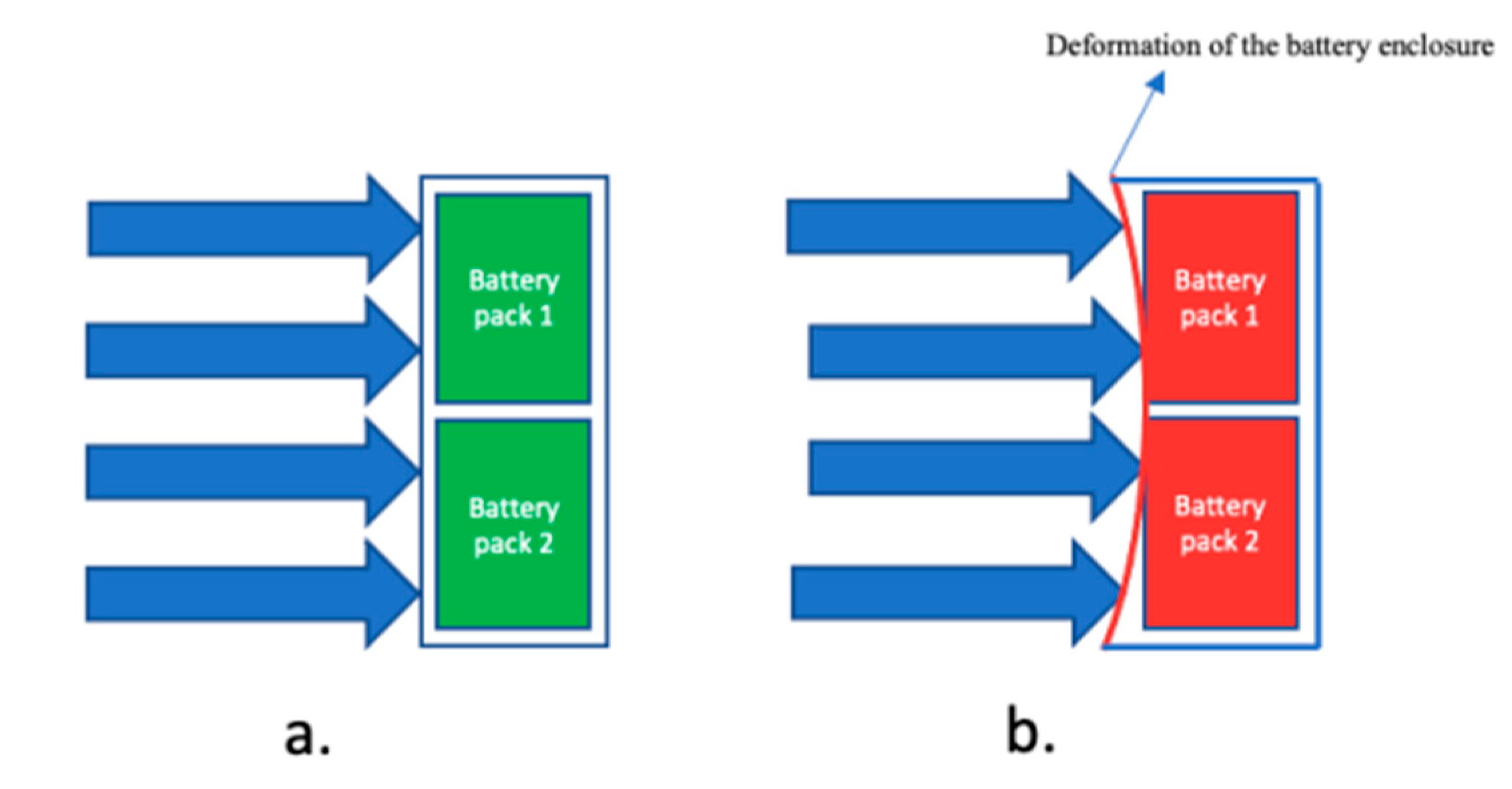
Figure 2.
Interface Boundary Diagram using the DFMMEA Method.
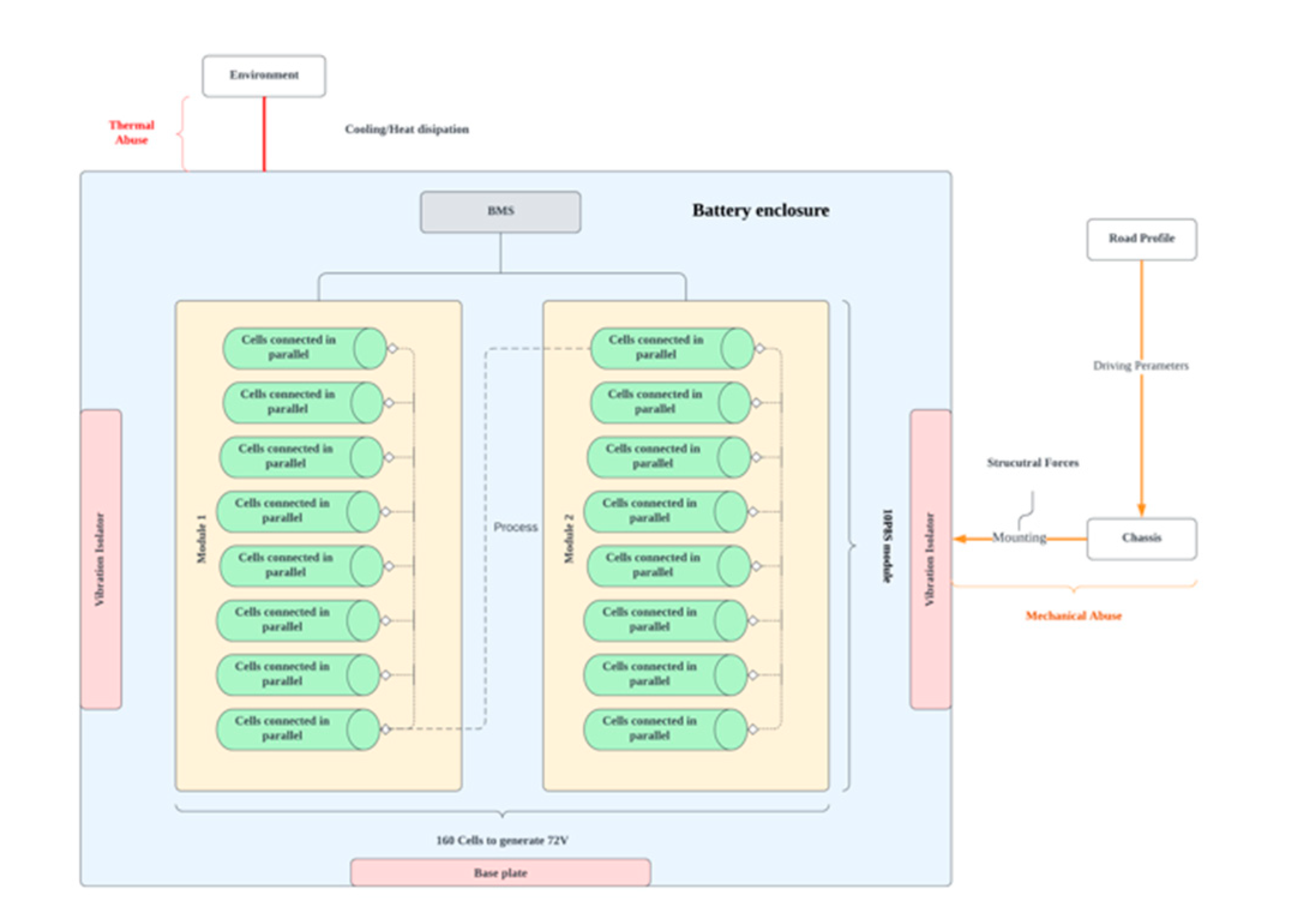
Figure 3.
Three-phase process of battery pack failure due to improper battery enclosure.
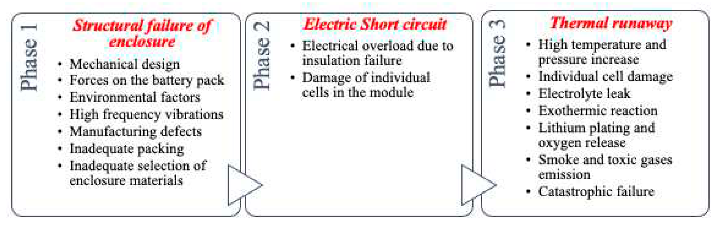
Figure 4.
ISO13232 crash configuration cross-plot, percentage of General Area of Damage (GAD) [38.]
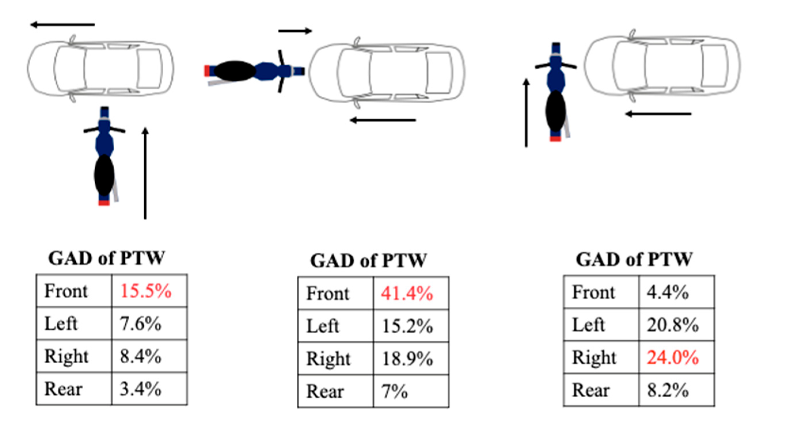
Figure 5.
Experimental model for dimensional accuracy
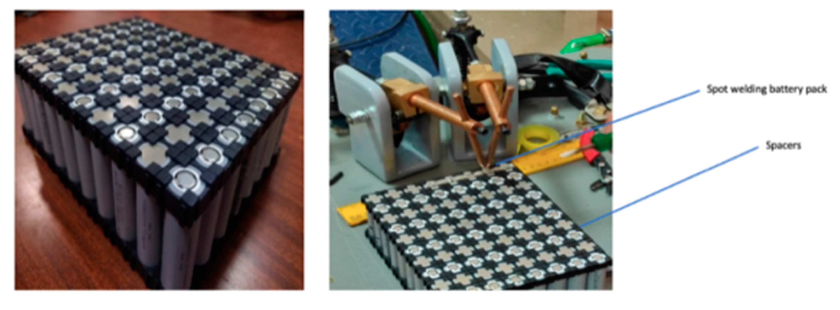
Figure 6.
Developed CAD model of 10P8S dual module horizontal battery pack.
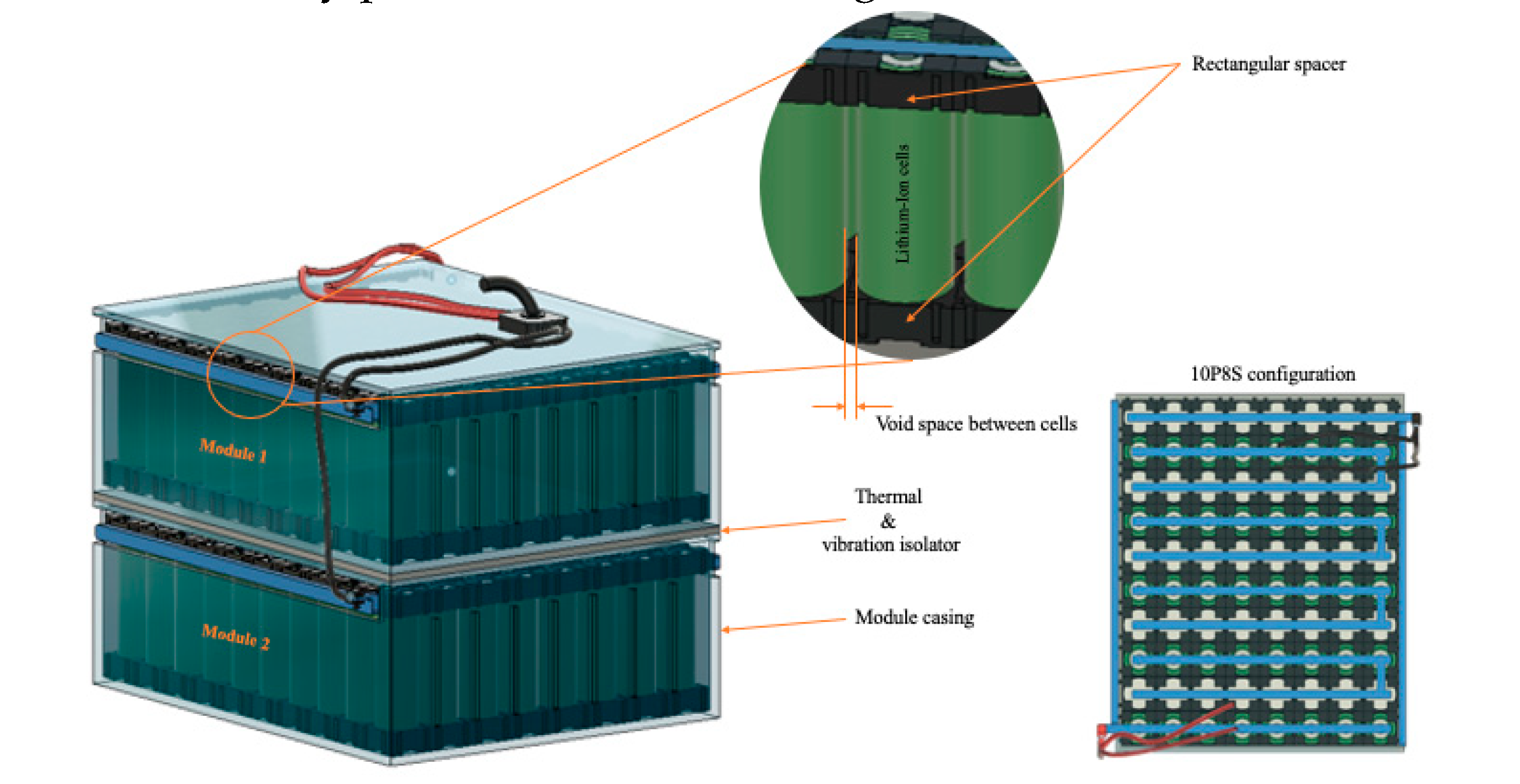
Figure 6.
Maximum Stress vs Thickness, required thickness of the material base plate with FOS 2.
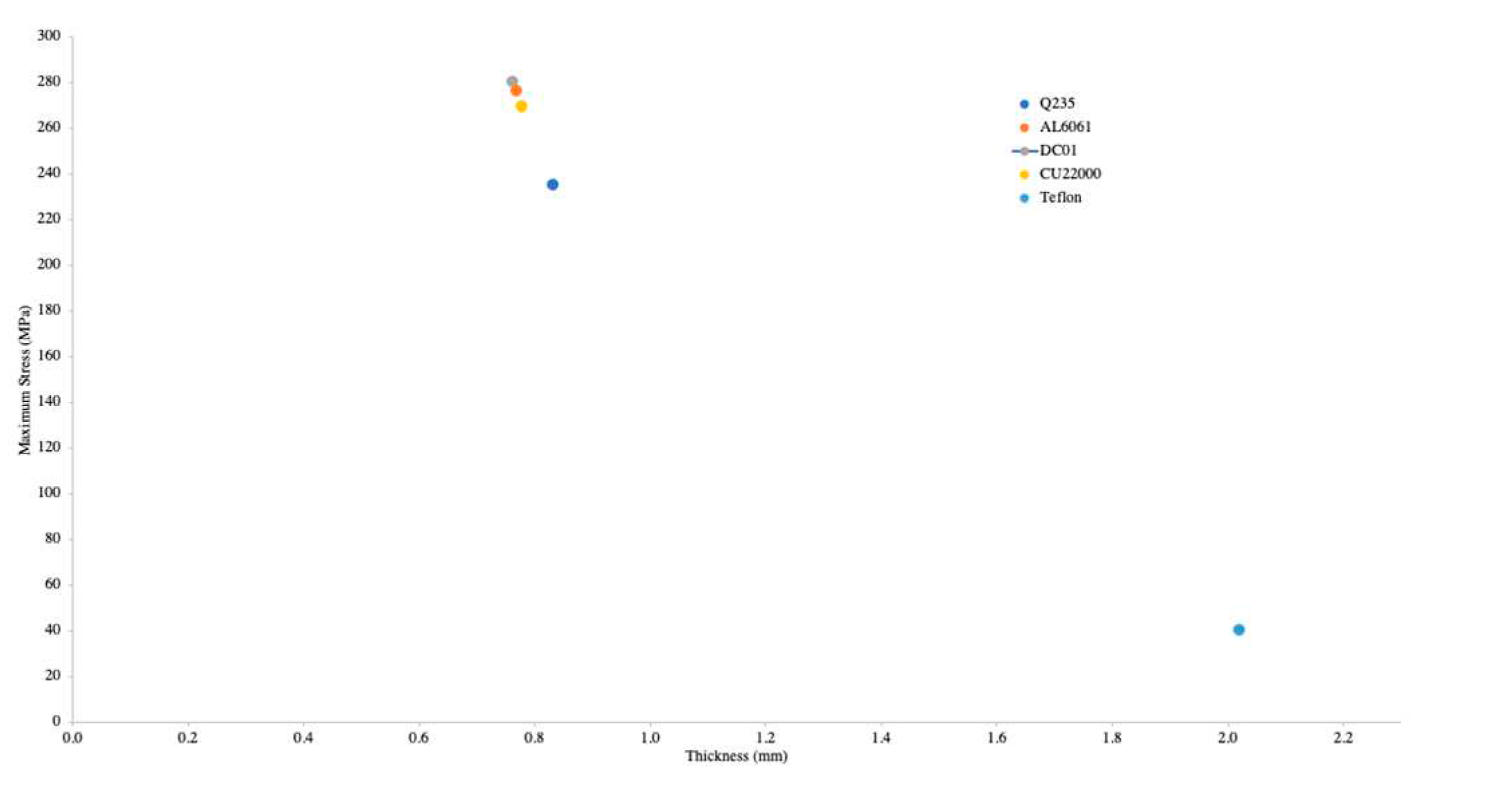
Figure 8.
Illustration of 3D CAD model of battery enclosure for ETW
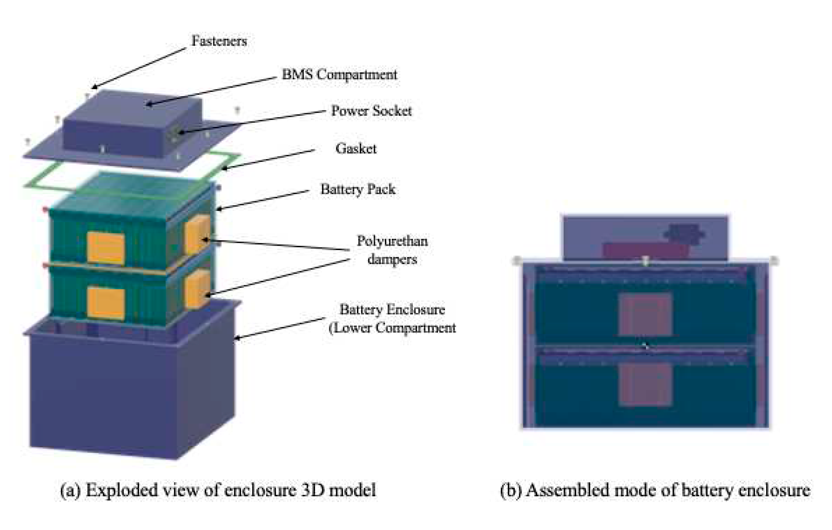
Figure 9.
Weight compositions of different materials with 3 mm and 4 mm thickness.
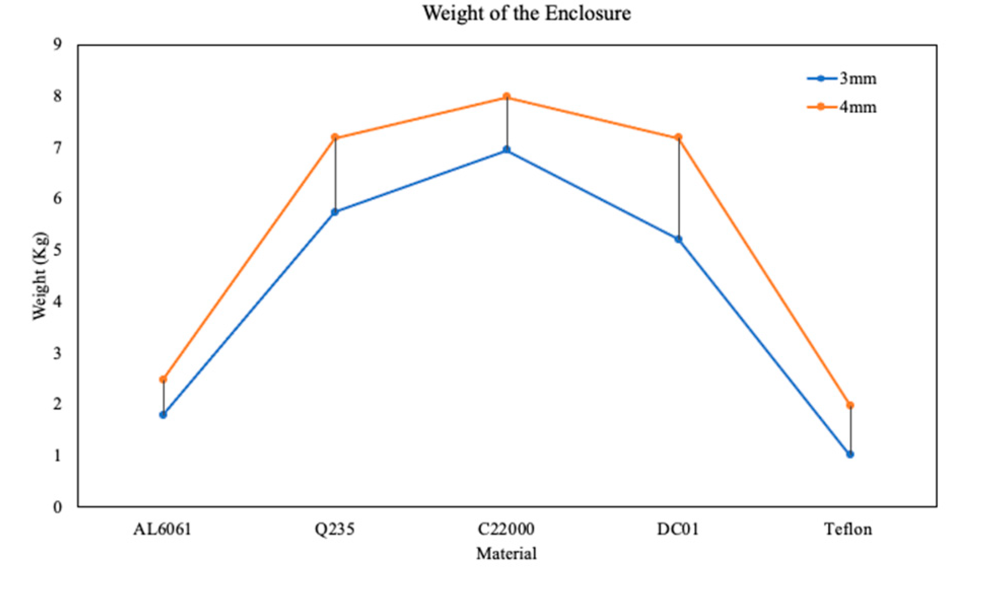
Figure 10.
(a) Maximum equivalent stress of different materials at 500 N side force; (b) Maximum equivalent stress of different materials at 1000 N side force.
Figure 10.
(a) Maximum equivalent stress of different materials at 500 N side force; (b) Maximum equivalent stress of different materials at 1000 N side force.
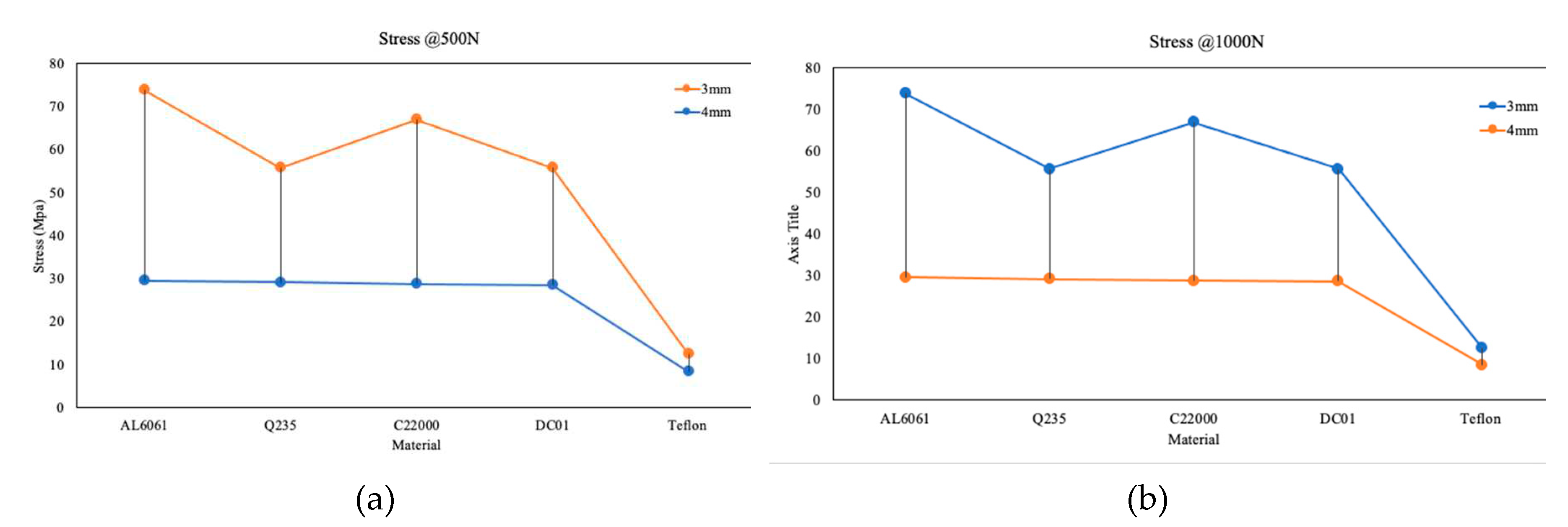
Figure 11.
(a)Maximum deformation of different materials at 500 N side force; (b) Deformation of different materials at 1000 N side force.
Figure 11.
(a)Maximum deformation of different materials at 500 N side force; (b) Deformation of different materials at 1000 N side force.
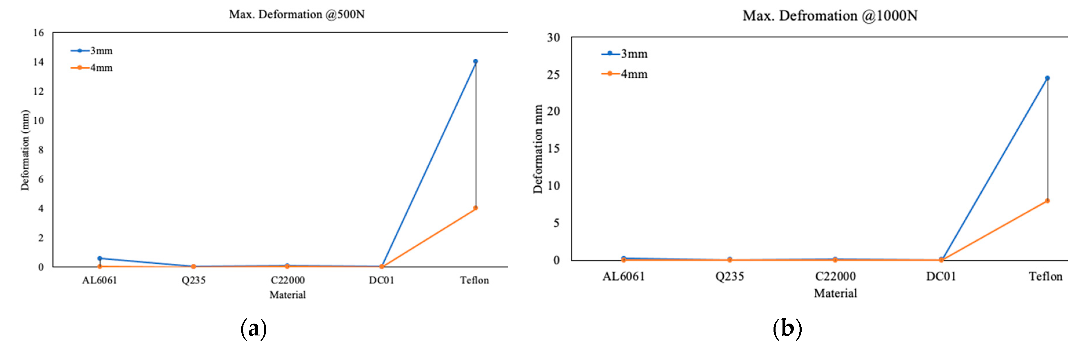

Table 1.
Structural Interface Matrix (SIM) of battery pack enclosure.
| Description | Interface Type |
Function | Measure | Failure type | Severity index |
|---|---|---|---|---|---|
| UC-Gasket | Touch | Seal to prevent moisture | Crush | Ingress of moisture or contaminants | M |
| UC-LC | Touch | Allow the assembly to lock with 6mm bolts and prevent loss of contact | Holding tight | Mechanical instability and separation of casing | H |
| LC-Vibration Isolators | Touch | Isolates the stress and deformation from the external force | Crush | Degradation of Isolators over time | L |
| Module-Thermal Isolators | Touch | Isolates the thermal and electrical conductivity | Crush | Uneven thermal dissipation from one module to another | H |
| Chassis-Battery casing | Touch | Distribution of mechanical loads and forces while vehicle operation | Structural integrity | Potential damage to the battery due vibrations and forces | H |
| Battery Casing-Environment | Heat convection | Transfer of ambient temperature to the battery module | Heat energy | Corrosion, Heat dissipation failure | H |
* H-High; M-Moderate; L-Low; UC-Upper casing; LC-Lower casing.
| Standard | Description |
|---|---|
| SAEJ240 | Life test for automotive storage batteries |
| SAEJ1766 | Practice for EV hybrid vehicle battery systems crash integrity testing |
| SAEJ1797 | Packaging of Electric Vehicle Battery Modules |
| SAEJ1798 | Recommended Practice for Performance Rating of Electric Vehicle Battery Modules |
| SAEJ2185 | Life test for heavy-duty Storage batteries |
| SAEJ2289 | Electric-Drive Battery Pack System: Functional Guidelines |
| SAEJ2344 | Technical Guidelines for Electric Vehicle Safety |
| SAEJ2380 | Vibration Testing of Electric Vehicle Batteries |
| SAEJ2464 | Electric Vehicle Battery Abuse Testing |
| SAE2929 | Electric and Hybrid Vehicle Propulsion Battery System Safety Standard |
Table 3.
Battery and Vehicle Specification of ETW
| Description | Specifications |
|---|---|
| Motor | BLDC, 3 kW, 27 Nm |
| Estimated Range | 120-140 km |
| Cell configuration | 8P10S |
| Maximum Speed | 100 kmph |
| Battery type | Lithium-ion cylindrical cell (18650), 3.7 V |
| Pack power, capacity | 72 V, 1.4 kWh, 19.2 Ah |
Table 4.
Volumetric Efficiency and occupancy rate of 160 cells.
| Description | Value |
|---|---|
| Number of cells per module (18650) | 80 |
| The volume of single battery cell | 16 cm3 |
| Weight of the battery pack (2 modules) | 7.2 kg |
| The volume of 80 cells in the pack | 1280 cm3 |
| The measured volume of a single module | 2240 cm3 |
| Volumetric Efficiency (For single module) |
63% |
| Volumetric Efficiency of the battery pack (Two modules) |
66% |
| Space Occupancy rate | 34% |
Table 5.
Selected Material Properties of Battery Enclosure
| Component | Material | δ |
ρ kg/m3 |
MPa |
MPa |
|---|---|---|---|---|---|
| Enclosure | Q235 | 7850 | 0.28 | 326.3 | 422 |
| Al 6061 | 2713 | 0.33 | 126.3 | 222.4 | |
| DC 01 | 7850 | 0.3 | 171.5 | 307.4 | |
| C22000 | 8800 | 0.31 | 76.49 | 275.5 | |
| Teflon | 2170 | 0.35 | 20.68 | 26.72 | |
| Mechanical or Thermal Isolators |
Polyurethane |
31.94 | 0.39 | 0.0041 | 0.144 |
Table 6.
Structural analysis of base plate under 2 g loading conditions.
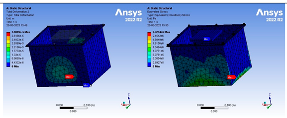 | |
| (a) Total Deformation (b) Equivalent stress Static analysis of enclosure with 3 mm thickness using AL6061 | |
| Maximum equivalent stress | 2.423 MPa |
| Maximum deformation | 0.0398 mm |
 | |
| (a) Total Deformation (b) Equivalent stress Static analysis of enclosure with 3 mm thickness using Q235 | |
| Maximum equivalent stress | 2.46 Mpa |
| Maximum deformation | 0.0136 mm |
 | |
| (a) Total Deformation (b) Equivalent stress Static analysis of enclosure with 3 mm thickness using DC01 | |
| Maximum equivalent stress | 2.46 Mpa |
| Maximum deformation | 0.0136 mm |
 | |
| (a) Total Deformation (b) Equivalent stress Static analysis of enclosure with 3 mm thickness using C22000 | |
| Maximum equivalent stress | 2.408 Mpa |
| Maximum deformation | 0.02411 mm |
Table 6.
Structural behaviour of different enclosure materials while taking the turn under 140 N force.
Table 6.
Structural behaviour of different enclosure materials while taking the turn under 140 N force.
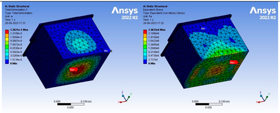
 | |
| (a) Total Deformation (b) Equivalent stress Static analysis of enclosure with 3 mm thickness using AL6061 | |
| Weight of the battery enclosure | 1.79 kg |
| Maximum equivalent strain (m/m) | 8.389⋅10-5 |
| Maximum equivalent stress | 10.61 Mpa |
| Maximum deformation | 0.048 mm |
 | |
| (a) Total Deformation (b) Equivalent stress Static analysis of enclosure with 3 mm thickness using C22000 | |
| Weight of the battery pack | 6.45 kg |
| Maximum equivalent strain | 5.0517⋅10-5 |
| Maximum equivalent stress | 5.53 Mpa |
| Maximum deformation | 0.029 mm |
 | |
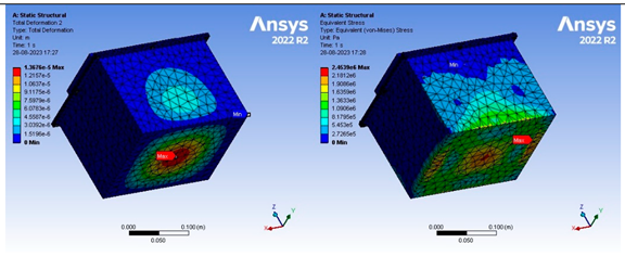
| (a) Total Deformation (b) Equivalent stress Static analysis of enclosure with 3mm thickness using Q235 | |
| Weight of the battery pack (kg) | 4.027(L)+1.715(U) |
| Maximum equivalent strain | 2.6621⋅10-5 m/m |
| Maximum equivalent stress (Mpa) | 8.088 |
| Maximum deformation (mm) | 0.23 |
 | |
| (a) Total Deformation (b) Equivalent stress Static analysis of enclosure with 3 mm thickness using Teflon | |
| Weight of the battery pack (kg) | 0.685 L+0.325 U |
| Maximum equivalent strain | 0.0051 |
| Maximum equivalent stress (Mpa) | 2.11 |
| Maximum deformation (mm) | 3.5 |
 | |
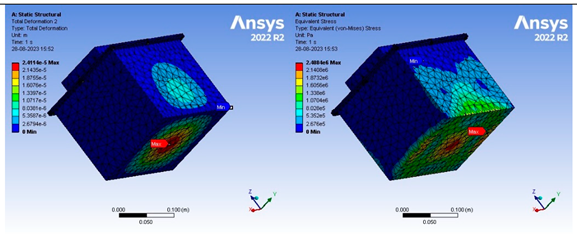
| (a) Total Deformation (b) Equivalent stress Static analysis of enclosure with 3mm thickness using DC01 | |
| Weight of the battery pack (kg) | 3.84L+1.37U |
| Maximum equivalent strain | 2.68e-5 |
| Maximum equivalent stress (Mpa) | 8.093 |
| Maximum deformation (mm) | 0.017 |
Table 8.
Structural behavior of different enclosure materials while taking the turn under 140 N force.
Table 8.
Structural behavior of different enclosure materials while taking the turn under 140 N force.
| Material | Description | Details |
|---|---|---|
| AL6061 | Mode 1 | 589.25 Hz |
| Mode 2 | 598.25 Hz | |
| Mode 3 | 591.34 Hz | |
| Ratio of Effective to Total mass | 0.234 x-direction |
|
| Q235 | Mode 1 | 829.38 Hz |
| Mode 2 | 837.97 Hz | |
| Mode 3 | 942.8 Hz | |
| Ratio of Effective to Total mass | 0.2331 x-direction |
|
| C22000 | Mode 1 | 589.66 Hz |
| Mode 2 | 596.28 Hz | |
| Mode 3 | 670.57 Hz | |
| Ratio of Effective to Total mass | 0.2382 x-direction |
|
| DC01 | Mode 1 | 829.01 Hz |
| Mode 2 | 837.63 Hz | |
| Mode 3 | 942.47 Hz | |
| Ratio of Effective to Total mass | 0.2332 x-direction |
Table 9.
Structural behavior of different enclosure materials while taking the turn under 140 N force
Table 9.
Structural behavior of different enclosure materials while taking the turn under 140 N force
 | |
| (a) Heat Flux (b) Temperature profile Steady state thermal analysis of AL6061 material casing | |
| Heat Flux | 16566 W/m2 |
| Maximum Temperature | 43.763°C |
 | |
| (a) Heat Flux (b) Temperature profile Steady state thermal analysis of Q235 material casing | |
| Heat Flux (W/m2) | 11324 W/m2 |
| Maximum Temperature | 44.78°C |
 | |
| (a) Heat Flux (b) Temperature profile Steady state thermal analysis of C22000 material casing | |
| Heat Flux | 13915 W/m2 |
| Maximum Temperature | 43.64°C |
 | |
| (a) Heat Flux (b) Temperature profile Steady state thermal analysis of DC01 material casing | |
| Heat Flux | 14208 W/m2 |
| Maximum Temperature | 44.726°C |
 | |
| (a) Heat Flux (b) Temperature profile Steady state thermal analysis of Teflon material casing | |
| Heat Flux | 3344 W/m2 |
| Maximum Temperature | 47.03°C |
Disclaimer/Publisher’s Note: The statements, opinions and data contained in all publications are solely those of the individual author(s) and contributor(s) and not of MDPI and/or the editor(s). MDPI and/or the editor(s) disclaim responsibility for any injury to people or property resulting from any ideas, methods, instructions or products referred to in the content. |
© 2023 by the authors. Licensee MDPI, Basel, Switzerland. This article is an open access article distributed under the terms and conditions of the Creative Commons Attribution (CC BY) license (http://creativecommons.org/licenses/by/4.0/).
Copyright: This open access article is published under a Creative Commons CC BY 4.0 license, which permit the free download, distribution, and reuse, provided that the author and preprint are cited in any reuse.


