Submitted:
25 August 2023
Posted:
29 August 2023
You are already at the latest version
Abstract
The degradation of Proton-exchange membrane fuel cell (PEMFC) gasket materials is crucial in electric vehicles as it can cause hazardous hydrogen fuel leaks, which are usually due to high temperatures, pressures, and hydrogen fuel exposure. Degradation of gasket materials in PEMFC presents a critical concern for electric vehicle safety due to potential hydrogen fuel leaks. This study utilizes finite element analysis (FEA) to assess the suitability of gasket materials for PEMFC applications, focusing on aging and tensile conditions. The dual degradation framework, incorporating contact pressure and von Mises stress, is employed to evaluate Liquid Silicon Rubber (LSR) and Ethylene Propylene Diene Monomer (EPDM) materials. Under aging techniques, the Yeoh model exhibits the least Mean Absolute Percentage Error (MAPE) and computational cost of 0.27 seconds, while the Ogden model records the highest computational cost of 0.89 seconds. In evaluating MAE, Root Mean Square Error (RMSE), and R-squared metrics, LSR and EPDM materials demonstrate respective averages of 0.25%, 0.275%, 0.945%, and 0.815%, 0.685%, 0.77%. Tensile testing (Uniaxial) reveals RMSE and MAE values of 0.30%, 0.40%, and 0.50%, 0.40%, respectively. FEA proves instrumental in identifying suitable gasket materials for PEMFC applications. LSR emerges as the superior choice, demonstrating enhanced FEA modelling performance under aging and tensile conditions. These findings contribute valuable insights to the design and development of improved gasket materials, bolstering the safety and reliability of electric vehicles.
Keywords:
contact pressure
; finite element analysis
; gasket material
; hyperelastic models
; PEMFC
; polynomial regression
; strain functions
; von Mises stress
1. Introduction
Proton-exchange membrane fuel cells (PEMFCs) are a type of hydrogen fuel cell that produces only water vapour as a byproduct. However, hydrogen fuel cells face several challenges, including the high cost of materials and the need for a reliable and efficient method of storing and generating hydrogen. Their applications range from transportation to stationary power generation to portable devices [1]. Research in PEMFCs and hydrogen fuel cells has focused on improving their performance, durability, and cost-effectiveness [2]. It involves developing new fuel cell materials and improving the design of fuel cell stacks. Furthermore, researchers are investigating more efficient and cost-effective ways to produce hydrogen, such as using renewable energy sources [3]. Fuel cells typically consist of three main components: an anode, a cathode, and an electrolyte membrane. Electrons flow through the cathode (negative electrode of the cell), and oxygen is reduced to form water. The anode is the positive electrode, where hydrogen ions are oxidized to form protons and electrons. The membrane electrolyte acts as a barrier between the cathode and anode, allowing ions to pass through while preventing electrons from flowing in the wrong direction. Together, these components generate electricity through the chemical reaction of hydrogen and oxygen [4]. The assembled PEMFC can be seen in Figure 1.
The gasket material used in hydrogen fuel cells is crucial in guaranteeing safe and effective operation. To stop the leaking of hydrogen gas and other fluids, it is in charge of sealing the various components of the fuel cell. Elastomers, polymers, and ceramics—materials that can tolerate high temperatures and pressures in fuel cells—are commonly used to create the gasket. The gasket must also withstand the corrosive effects of hydrogen and other chemicals in the fuel cell environment. The durability and functionality of the fuel cell system depend on the gasket’s installation and maintenance procedures. Silicone rubber, ethylene propylene diene monomer (EPDM), and polytetrafluoroethylene (PTFE) are typical gasket materials for fuel cell stacks [5]. These gasket materials/sealants are ideal for applications involving hydrogen fuel cells due to their outstanding chemical and physical characteristics. Fluoroelastomers and PTFE are known for their chemical and high-temperature resistance, and EPDM and silicon rubber are recognized for their flexibility and durability [6].
Most accelerated aging methods for hydrogen fuel cells involve exposing them to high temperatures, high humidity, and sulfuric acid. It enables manufacturers and researchers to test the fuel cells’ toughness and lifetime before using them in practical applications by simulating the harsh circumstances that the cells could encounter during routine operation. To replicate the sulfur impurities that could be present in the hydrogen fuel utilized in the cells, sulfuric acid is added to the testing environment. The test results can assist researchers in identifying and resolving any design or component problems that might contribute to the fuel cells’ rapid degradation [7,8,9]. The performance and toughness of the bipolar plates of a hydrogen fuel cell are assessed under contact pressure. To simulate the operational circumstances of the fuel cell, a specific force is applied to the contact region between the bipolar plate and the membrane electrode assembly (MEA) during the test. A mechanical press or load cell applies pressure to the material before and after the trial, and the fuel cell’s electrical output is monitored. The test findings can be used to assess the bipolar plate material’s quality, the MEA’s dependability, and the fuel cell’s overall performance [9,10,11].
To maintain its seal, the material must also resist deterioration and brittleness over time. The performance of these materials in a hydrogen fuel cell environment can be assessed using tensile testing, which can also help identify the optimum material for a particular application [12,13,14,15,16]. The outcomes of the tests can also be used to compare various gasket materials and choose the best choice for the system. It is crucial to consider the possibility of degradation owing to the challenging operating conditions of the fuel cell when selecting a gasket material for a hydrogen fuel cell. High pressures and temperatures are encountered while operating hydrogen fuel cells, as well as severe chemicals and gases. Choosing a gasket material that can resist these circumstances without deteriorating over time is crucial. PEMFCs have shown great promise as clean and efficient energy conversion devices for various applications. The performance and durability of PEMFCs depend on the integrity of their components, with gasket materials being critical for maintaining the fuel cell’s sealing efficiency. LSR and EPDM are popular for PEMFC gaskets due to their excellent chemical resistance, elasticity, and compatibility with the fuel cell environment [17,18]. The contributions of this study are highlighted below:
- The study addresses the research gap by providing a comprehensive and direct comparison between two widely used gasket materials, LSR and EPDM, specifically in PEMFC applications.
- The study generates experimental data for LSR and EPDM gasket materials under varying contact pressures representative of real-world PEMFC operating conditions. This experimental data is essential for validating the subsequent Finite Element Analysis (FEA) models and enhancing the accuracy and reliability of the study’s findings.
- By employing advanced Finite Element Analysis using the Marc software, the study extracts strain functions for both LSR and EPDM gaskets. This approach is significant as it enables researchers to understand how each material responds to different contact pressures, providing valuable information on their mechanical behaviour and deformation characteristics.
- The study’s focus is on evaluating the contact pressure distribution and Von Mises stress distribution for LSR and EPDM gaskets. These analyses shed light on each material’s sealing efficiency and mechanical stability under varying loading conditions, directly addressing the research gap concerning the structural integrity and long-term reliability of PEMFC gasket materials.
- The study aims to assess the accuracy of various hyperelastic models, such as Ogden, Gent, Mooney-Rivlin, Yeoh, Neo-Hookean, and Arruda-Boyce, in representing the mechanical behaviour of LSR and EPDM gasket materials. By evaluating these models and their predictions against experimental and FEA data, this research will provide valuable insights into the most appropriate hyperelastic model for accurately simulating the behaviour of gaskets in PEMFC applications.
2. Motivation, Literature Review, and Related Works
Despite their prevalent use, a comprehensive comparative study between LSR and EPDM as PEMFC gasket materials is lacking in the current literature. This research addresses this knowledge gap and provides valuable insights into materials’ mechanical behaviour and performance under realistic operating conditions. The study will extract strain functions by employing experimental data and advanced FEA to understand how each material responds to different contact pressures, ensuring accurate predictions of their behaviour during fuel cell operation. A paper investigates the degradation of silicone rubber, EPDM and a developed EPDM 2 compound as gasket materials in PEMFCs. The study compares the changes in properties and structure of a silicone rubber gasket caused by actual fuel cell use and accelerated aging in acidic solutions. The results show that acid hydrolysis is the primary mechanism of silicone rubber degradation and that TFA solution has a more aggressive effect on silicone rubber than sulphuric acid and Nafion solutions. EPDM 2 compound showed good performance with a low compression set value, making it a potential replacement for silicone rubber in PEMFCs [19]. A study investigates the degradation of silicone rubber gaskets used in PEMFCs. The researchers found that the gaskets’ hardness increases and weight decreases with increasing temperature cycles, leading to cracks on the surface and changes in surface chemistry due to de-crosslinking and chain scission. The results highlight the importance of proper gasket materials in maintaining the electrochemical performance of PEMFCs over their long-term operation [20]. A study examined how silicone rubbers of varying hardnesses degraded in various water solutions at 80 C. As a result of extended exposure to acidic aqueous solutions, silicone rubbers decomposed more severely, according to the results. The study also found that weight loss measurements alone may not accurately characterize degradation and that strong acids led to significant cracking and void formation [21]. For optimal performance, the elastomeric gasket materials for PEM fuel cells are exposed to harsh environments and must have physical and chemical stability. A paper investigates the chemical degradation of five materials in a simulated fuel cell solution using DMA, analyzing storage, loss modulus, and tan to determine glass transition temperature and other properties over 63 weeks [22]. A study examines the stress-strain distribution of the sealing system in single-cell and multi-cell constructions at various operating temperatures using the steel-strip PEMFC model. Temperature and other parameters impact the sealing performance and mechanical behaviour of PEMFCs, as shown by the analysis of the impacts of compression ratio, fluid pressure, dislocation, and dimension on these two aspects [23]. A paper investigates using multilayered EPDM seal materials in PEM fuel cells for sustained long-term operation. The study finds that multilayered vulcanizates have higher hardness, better sealing capacity, and dimensional stability than blended materials, with nearly the same gas permeability. Aging tests show that while mechanical properties decline with time, multilayered vulcanizates perform better than blended ones [24]. A paper analyzes the impact of rubber material selection on the sealing performance of compression packers in multi-stage fractured horizontal wells. Constitutive experiments were conducted, and finite element models were established to study the influence of rubber materials and casing thickness on sealing performance under various setting pressures. The results show that the sealing performance decreases as the set pressure increases, and the B75 material was found to have the best sealing performance. This research provides essential information for designing compression packers and has significant implications for successfully implementing horizontal well multi-stage fracturing [25]. A paper investigates the chemical degradation of five elastomeric gasket materials in a simulated and aggressive accelerated fuel cell solution for up to 63 weeks. Using optical microscopy, weight loss monitoring, atomic absorption spectrometer analysis, and ATR-FTIR spectroscopy, the study reveals that CR and LSR are not as stable as the other three materials, and FSR appears to be the most stable [26]. A paper examines the change in properties and structure of silicone rubber gaskets used in a fuel cell stack. The study compares the effects of actual fuel cell use on accelerated aging under elevated temperatures and acidic conditions. Results show that acid hydrolysis is the leading cause of degradation and that accelerated aging tests accurately reflect the conditions of a fuel cell environment [27]. The long-term chemical and mechanical stability of gaskets in PEM fuel cells is critical. A study investigated using silicone rubber specimens subjected to different compression loads and simulated environments. The weight change, morphological changes, and surface chemistry were studied using optical microscopy, ATR-FTIR, and XPS. The results showed significant changes in surface morphology, surface chemistry, and mechanical properties due to exposure to the simulated environments and compression loads over time. The acid concentration and compression load significantly impacted the silicone rubber material’s degradation [28,29]. A study uses hyperelastic models to evaluate the sealing effect of a flat rubber ring (FRR) in a roller bit. The Yeoh–revised model, based on single-axis compression stress, predicts Mises stress more accurately than the Yeoh model. The study demonstrates that the Yeoh–revised model better predicts the FRR’s sealing effect and Mises stress distribution, aiding in FRR structure optimization for improved longevity in roller bits. The model achieves the highest R2 value of 0.9771, effectively addressing FRR’s soft property and contributing to more precise stress calculations [30]. A study investigates the dynamic friction process of rubber seals in pneumatic servo systems, considering the influence of geometric errors. Rubber seals’ friction force and contact area were studied using a self-made friction test platform. A numerical model using finite element simulation revealed the impact of machining errors (roundness and straightness) on friction characteristics. Synergy effects of roundness and straightness in rubber seal friction behaviour were explored, contributing to the accurate prediction of cylinder dynamic mechanical properties [31]. This study investigates the influence of rubber hardness on tissue paper embossing, considering different configurations of rubber plates with varying hardness. Mechanical properties, softness, and bulk of the tissue products were evaluated. A Finite Element Model replicating experimental results supports the use of rubber rolls with low hardness internally and high hardness externally. Optimizing rubber roll hardness and configuration in embossing operations can enhance the critical properties of tissue paper products, providing valuable insights for the industry [32]. A study presents a comparative analysis of 16 hyperelastic models for neoprene gaskets under uniaxial tensile loading. The selection of an appropriate model is essential for accurately predicting gasket behaviour when limited experimental data is available. The research provides insights into the most suitable hyperelastic constitutive model, ensuring both accuracy and safety margin for neoprene gasket applications, mitigating the risks associated with leakages and enhancing overall safety in industrial and domestic appliances [33]
3. Theoretical Backgrounds
PEMFC gasket material is crucial in fuel cell technology and serves as a seal between the different layers of the fuel cell stack, allowing the flow of hydrogen and oxygen while preventing leaks. The theoretical background of PEMFC gasket material revolves around its ability to withstand high temperatures, provide excellent chemical stability and high electrical conductivity, and exhibit high compression resilience. Additionally, it should have low gas permeability to maintain a high level of performance. The choice of material depends on various factors, including fuel cell operating conditions, compatibility with the other components, and cost [34,35,36,37,38].
3.1. Overview of Gasket Material Selection
Gasket materials are critical in sealing, insulation, and vibration reduction in various automotive, aerospace, and industrial equipment applications. Selecting suitable gasket material depends on several factors, such as temperature, pressure, fluid compatibility, and chemical resistance. The most common gasket materials include EPDM, FKM, LSR, and VMQ. EPDM is a synthetic rubber known for its excellent weather, ozone, and aging resistance. It is suitable for various applications and can handle temperatures from -60°C to 150°C. EPDM is also compatible with water, steam, and various automotive fluids. EPDM gaskets are widely used in automotive applications such as radiator hoses, coolant systems, and washer systems [39,40,41,42,43]. LSR is a silicone rubber produced in liquid form and cured to form a solid rubber. LSR offers excellent weather and aging resistance, a low compression set, and high tear resistance. It can handle temperatures from -60°C to 200°C and is suitable for applications requiring high-temperature stability, chemical resistance, and low toxicity [44,45,46,47,48,49,50,51]. FKM (Fluoroelastomer) is a synthetic rubber known for its excellent chemical and heat resistance. It can handle temperatures up to 200°C and is suitable for aggressive chemical environments. FKM gaskets are widely used in fuel systems, chemical processing, and automotive engine seals. VMQ (Viton-A) is a fluoroelastomer known for its excellent chemical and heat resistance. It can handle temperatures up to 204°C and is suitable for aggressive chemical environments. VMQ gaskets are widely used in fuel systems, chemical processing, and automotive engine seals [52,53,54,55,56]. Selecting the suitable gasket material depends on the specific application requirements such as temperature, pressure, fluid compatibility, and chemical resistance. EPDM, FKM, LSR, and VMQ are some of the most common gasket materials and offer unique benefits and limitations. A comprehensive material selection process that considers each material’s specific application requirements and the benefits and regulations is necessary to ensure optimal performance.
3.2. Overview of Hyper-elastic Constitutive Models
Hyperelastic constitutive models mathematically represent the stress-strain relationship of rubber-like materials. These models are crucial in designing and analysing many technical applications because they forecast how rubber-like materials behave under various loading circumstances. Ogden, Yeoh, Mooney Rivlin, Neo Hookean, Arruda Boyce, and Gent are some of the most used hyperelastic constitutive models [57]. A well-known hyperelastic constitutive model designed to simulate the mechanical behaviour of rubbery materials is Ogden’s (1984) model. The right Cauchy-Green deformation tensor’s first and second invariants are assumed to be functions of the material’s strain energy density in this model. The Yeoh (1993) model is a more intricate hyperelastic constitutive model created to represent rubber-like materials’ nonlinear and anisotropic behaviour. The first and second invariants of the right Cauchy-Green deformation tensor and the first invariant of the deviatoric tensor are assumed to be functions of the strain energy density of the material in this model. A two-parameter hyperelastic constitutive model called the Mooney Rivlin (1940) model was created to simulate the mechanical behaviour of rubber-like materials. The right Cauchy-Green deformation tensor’s first and second invariants are assumed to be a function of the material’s strain energy density in this model [58,59]. A one-parameter hyperelastic constitutive model called the Neo Hookean (1949) model was created to simulate the mechanical behaviour of rubber-like materials. The deviatoric component of the right Cauchy-Green deformation tensor is assumed to be proportional to the strain energy density of the material in this model. An eight-parameter hyperelastic constitutive model called the Arruda Boyce (1993) model was created to simulate the mechanical behaviour of rubber-like materials. The first and second invariants of the right Cauchy-Green deformation tensor and the first invariant of the deviatoric tensor are assumed to be functions of the strain energy density of the material in this model. A three-parameter hyperelastic constitutive model called the Gent (1995) model was created to represent the mechanical behaviour of rubber-like materials accurately. The first and second invariants of the right Cauchy-Green deformation tensor and the first invariant of the deviatoric tensor, [60], are assumed to be functions of the strain energy density of the material in this model. These hyperelastic constitutive models offer different levels of complexity and precision to represent the mechanical behaviour of rubber-like materials. The engineering application’s unique needs and the accuracy in predicting how the rubber-like material will behave will determine the best model [61,62,63,64,65].
4. Proposed Gasket Material FEA Model
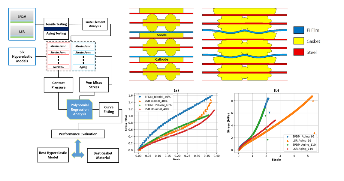
Selecting the suitable gasket material is crucial in ensuring the reliable and efficient performance of a Proton Exchange Membrane Fuel Cell (PEMFC). Following these steps, you can create a PEMFC gasket material selection framework to help you select the best gasket material for your specific fuel cell application. During FEA simulations, contact pressure and von Mises stress are calculated based on the component’s material properties, loads, and geometric characteristics. The results of these simulations can be used to make informed design decisions and improve the performance and reliability of the component. Figure 2 explains the breakdown process for the gasket materials and decision-making paradigm.
4.1. Experimental Testing for the Gasket Materials
Biaxial and uniaxial testing determine the mechanical properties of materials, such as strength, stiffness, and ductility. The primary difference between the two tests is the direction of the applied force. Uniaxial testing involves applying a single force to the tested material in one direction. In contrast, biaxial testing uses two forces in different directions simultaneously. The testing result can reveal necessary information about the material’s behaviour and properties. Generally, uniaxial testing provides a more superficial, straightforward analysis of a material’s behaviour under tension or compression. When conducting an experimental study to choose the best material, it is essential to consider the application’s specific requirements. For example, if the material is subjected to complex loads in multiple directions, biaxial testing may provide more accurate information about its behaviour in real-world applications. Conversely, uniaxial testing may be sufficient if the material is only subjected to unidirectional forces. On one hand, Figure 3a shows the experimental procedure capturing the uniaxial and biaxial testing. The testing was conducted using the LLOYD material testing equipment produced by AMETEK Sensors, Test and Calibration (STC). On the other hand, Figure 3b represents the aging experimental procedure using the sulphuric solution immersed for 3000 hours, equivalent to 125 days.
Interestingly for the aging procedure, the gasket material was cut into appropriate sizes and shaped suitable for testing and ensured that the samples were free from defects or contamination. A sulfuric acid solution was prepared with a concentration relevant to the operational conditions of the PEMFC. The solution matched the typical sulfuric acid concentration in the fuel cell environment. This concentration is usually in the range of 30% to 85% sulfuric acid by weight. The aging chamber or exposure apparatus was set up where the gasket material samples would contact the sulfuric acid solution. The aging temperature and the duration for which the samples will be exposed to the sulfuric acid were determined. The temperature and aging time were pegged to 95C to 110C to represent the expected operating conditions of the PEMFC. The gasket material samples were immersed in the sulfuric acid solution within the aging chamber. It was ensured that the gasket samples were fully submerged and not exposed to air during aging. The aging conditions were carefully monitored to maintain the desired temperature and acid concentration. Based on the aging time, the gasket samples were removed periodically from the chamber at predefined intervals to assess changes in the material properties over time.
Figure 4 shows the cross-section of the gasket material comprising of the anode, cathode, the pi film and the steel with their labels showing respectively as assembled in the figure. Ultimately, the best material choice will depend on various factors, including the specific properties required for the application, the cost and availability of different materials, and the results of any experimental testing. In this study, we have carried out the experimental tensile using both the biaxial and uniaxial techniques to have a comprehensive paradigm for selecting the best gasket material. It can be seen from Figure 5a it consist of four plot under the tensile condition, namely EPDM Biaxial (blue colour), LSR Biaxial (orange colour), EPDM Uniaxial (green colour) and LSR Uniaxial (red colour), respectively. Interestingly, another set of gasket samples was exposed to compression testing at varying temperatures, and the resulting data is plotted and shown in Figure 5b.
4.2. Gasket Material FEA Modelling Characterization
Modelling and characterization of gasket materials can be done using contact pressure and Von Mises stress. The utilization of the MARC program involves a structured sequence of steps to conduct FEA modelling. This process encompasses several crucial stages, including defining element types, establishing geometric properties, inputting material property values, configuring contact interactions, specifying boundary conditions, setting up load cases, and configuring job parameters. Upon completing these steps, the analysis generates insightful results that are pivotal for understanding the behaviour of rubber components. The primary focus is on critical parameters such as von Mises stress, contact pressure, and deformation. These parameters play a pivotal role in assessing the structural integrity and performance of the components under scrutiny. Contour bands are employed to comprehend the distribution of these numerical values across the analyzed model. These bands offer a visual representation of the parameter variation, allowing for the identification of peak values in distinct regions like the anode gasket, cathode gasket, and plate. The evaluation of contact pressure is particularly noteworthy, which is treated as a vector quantity. The analysis allows for generating load characteristic graphs. These graphs further aid in comprehending load-bearing trends and stress variations under different conditions. This study details a comprehensive methodology for employing the MARC program in FEA modelling. By systematically following the outlined steps, valuable insights into the mechanical behaviour of the gasket components are gained, highlighting critical parameters such as von Mises stress, contact pressure, and deformation. The utilization of contour bands and load characteristic graphs enhance the clarity and depth of the analysis, facilitating a robust understanding of component performance. Following the illustration of the FEA individual process comprising of contact pressure and Von Mises stress as shown in Figure 6, the resulting modelling parameters for each hyperelastic model are summarized in Table 1 and Table 2 for the EPDM and LSR gasket material respectively. The two gasket materials under study, namely EPDM and LSR, were subjected to both contact pressure and von Mises stress. In contrast, the respective material parameters were recorded for each of the hyperelastic models, namely: Mooney Rivlin(3), Yeoh(3), Ogden(6), Neo Hookean(1), Arruda Boyce(2), and Gent(2) with their respective number of parameters in the bracket.
4.3. FEA Modelling Visualization
Contact pressure heatmap visualization depicts the distribution of forces exerted between contacting surfaces within a simulated structure. MARC software achieves this by assigning colours to different pressure levels. The warmer red and orange denote higher pressures in the resulting heatmap, while cooler colours like blue and green represent lower pressures. This visualization aids in identifying regions of concentrated force transmission, potential stress concentrations, and contact separation or sliding areas. The von Mises stress heatmap portrays the distribution of equivalent stress levels, combining different types of stresses to assess a material’s potential for yielding or failure. By employing colour gradients, this visualization method offers insight into stress concentrations, critical areas of deformation, and potential failure points. Warmer colours signify higher stress levels, while cooler ones represent lower ones.
The resulting visualization following the FEA modelling was designed to capture the contact pressure (left) with its varying contact pressure (MPa) and displacement and Von Mises stress(right) with its varying internal deformation (MPa) and displacement (mm). With precedence to the original hyper mesh, Figure A1, Figure A2 and Figure A3 show the modelling visualization for the EPDM gasket material. In contrast, Figure 7, Figure 8 and Figure 9 show the modelling visualization for the LSR gasket material under tensile conditions (Uniaxial and Biaxial). Under the aging conditions with varying temperature and working conditions, the Figure A4, Figure A5 and Figure A6 showing the FEA visualization for the EPDM material under aging conditions while Figure 10, Figure 11 and Figure 12 shows the FEA visualization for the LSR material under aging conditions. In summary, the FEA modelling visualization notably shows high contact pressure heatmap mostly under uniaxial tensile testing compared to the biaxial tensile testing conditions. Also, there were significant concentrations looking at the Mooney Rivlin and Ogden models for both the contact pressure and Von Mises stress as shown in Figure A1 and Figure A2 respectively under the EPDM materials. However, in the LSR materials, there was more concentration for Mooney Rivlin, Yeoh and Ogden, as shown in Figure 7 and Figure 8. Interestingly, under the aging condition, it can be noted from the FEA visualization that under EPDM material, the Mooney Rivlin and Ogden Model had a substantial concentration for both the 95 degrees and 110 degrees analysis for the PEMFC. The Figure A4 and Figure A5 give better representation for the analysis. However, under the LSR material for the aging condition, there was little or no concentration at both temperature ranges and also at each of the six hyperelastic models. This further prompt the need to access the resulting modelling data from the FEA for further assessment in other to aid the PEMFC gasket material selection framework between EPDM and LSR, respectively.
4.4. FEA Modelling Output and Curve Fitting Assessment
From Figure 13, the corresponding output from the finite element analysis under aging conditions for the LSR and EPDM materials is shown. The respective hyperelastic models, namely Mooney Rivlin, Ogden, Yeoh, Neo Hookean, Arruda Boyce and Gent, are used for modelling the gasket materials (LSR and EPDM) at varying temperatures and working hours (3000).
The resulting plot in Figure 13 shows an almost similar trend for their respective output. The assessment of the contact pressure of a material typically involves measuring the pressure distribution between two contacting surfaces. It is often done using pressure-sensitive films or sensors, which can be placed between the surfaces to be measured. Contact pressure assessment is essential in many applications where two materials are in contact, such as manufacturing processes, collaborative design, and biomechanical analysis. The contact pressure between two materials can affect the wear and deformation of the materials and can also impact the overall system’s performance.
The FEA modelling output from the MARC program provides insights into the behaviour of materials during a uniaxial testing process. Through computational simulations, FEA predicted how the gasket material responds to applied forces, helping to understand its mechanical properties. The output includes stress and strain distributions across the specimen, indicating high-stress concentration or deformation regions. Additionally, FEA yields information on load-displacement curves, enabling the characterization of material elasticity, yield point, and ultimate strength. It also reveals critical points such as fracture initiation and propagation. The simulation aids in identifying potential failure modes and validating experimental results. By offering a comprehensive view of the material’s response to uniaxial loading, FEA modelling enhances our comprehension of material behaviour and assists in designing reliable structures across various industries. Figure 14 shows the visualization of the von Mises stress output at 40% displacement for the FEA modelling.
4.5. Proposed Non-Linear Regression Analysis
Polynomial and exponential regression are standard techniques for curve fitting in machine learning and data analysis. While both methods aim to model a relationship between a dependent variable and one or more independent variables, they differ in terms of the model’s functional form. Polynomial regression is a type of regression analysis in which the relationship between the dependent variable and one or more independent variables is modelled as an nth-degree polynomial. The polynomial function can be expressed as:
where y is the dependent variable, x is the independent variable, and a0, a1, a2, ... are the coefficients that need to be estimated. Polynomial regression can capture complex nonlinear relationships between the variables and can fit a curve to the data with high accuracy. However, higher-degree polynomials can lead to overfitting, which can reduce the model’s generalization ability. Exponential regression, on the other hand, models the relationship between the dependent variable and one or more independent variables as an exponential function. The exponential function can be expressed as:
where y is the dependent variable, x is the independent variable, and a and b are the coefficients that need to be estimated.
The choice of polynomial regression for this study is borne out of the nature of the data and research question at hand. The latter (exponential regression) is also a great technique for modelling and the curve-fitting process. It is essential to evaluate the performance of the models using appropriate metrics and to interpret the results. The Figure 15 serves as the curve fitting assessment for the data output from the aging conditions with 3000 working hours and varying temperature ranges of 95 degrees and 110 degrees, which falls in line with the working temperature of a typical PEMFC system (60 - 120 degrees). The outputs of the hyperelastic models—contact pressure and Von Mises stress data—should ideally be equal to the real modelling data; however, because of the underlying assumptions of each model, miscalculations are unavoidable. A relationship (linear, quadratic, and/or polynomial) between the model outputs and the contact pressure and Von Mises data allows for evaluating the respective models’ curve similarity with the real contact pressure and Von Mises data. Figure 16 and Figure 17 shows the curve fitting assessment plot using a combination of polynomial and linear regression for the EPDM and LSR materials, respectively, under the tensile condition (Uniaxial). We decided to proceed only with the uniaxial dataset because there were not enough meaningful concentrations across selected hyperelastic models for the two materials (EPDM and LSR), hence the need to proceed mainly with the uniaxial dataset.
5. Non-Linear Regression Performance Metrics
Regression metrics are used to evaluate the performance of a regression model, which predicts a continuous numerical output variable based on one or more input variables. Some standard regression metrics and their mathematical expressions are:
Mean Squared Error (MSE) measures the average squared difference between the predicted and actual values. It is given by:
where n is the number of samples, is the actual value, and is the predicted value.
Root Mean Squared Error (RMSE): This is the square root of the MSE and provides the average error in the same units as the output variable. It is given by:
The average absolute difference between the predicted and real values is measured by mean absolute error (MAE). It is given by:
R-Squared (): This measures the proportion of variance in the output variable that the model explains. It ranges from 0 to 1, with higher values indicating a better fit. It is given by:
where is the mean of the output variable.
Mean Absolute Percentage Error (MAPE) measures the average percentage difference between the predicted and actual values. It is given by:
where is the actual value.
These metrics help evaluate a regression model’s performance and select the best model for a particular problem.
Figure 18 shows the regression assessment plot considering the aging conditions deployed to the PEMFC gasket material (EPDM and LSR). On the left is a plot showing the performance of the six hyperelastic models for the EPDM and LSR gasket materials candidate using the MAPE metrics. The least model average of the six hyperelastic models is the Gent with 0.23% modelling error, with the Ogden model with the highest MAPE of 1.49%. Considering other metrics(R2, RMSE and MAE) to select the best material considering the aging conditions of varying temperatures of 95 and 110 degrees. It can be noted from the bar plot that the LSR at 95 degrees had the highest value of R2, with the least being the EPDM at 110 degrees giving superiority to the LSR material over the EPDM. The root means square error (RMSE) showed the LSR material better than the EPDM material with the average least value of 0.3% and 0.5%, respectively. Likewise, the mean absolute error (MAE) showed the LSR gasket material with the least average value of 0.25% compared to the average value of EPDM gasket material at 0.75%. Overall, the LSR gasket material had better performance compared to the EPDM under aging conditions.
Subsequently, we tried to check the performance metrics of the EPDM and LSR material, considering uniaxial tensile conditions. Figure 19 and Figure 20 give insight into the regression metrics analysis under uniaxial tensile conditions for the PEMFC gasket materials. The LSR MAPE metrics show the anode superiority over the cathode area of the gasket. Subsequently, the Yeoh model had the least MAPE result at both the cathode and anode area, with the Gent showing the highest percentage of modelling error. The EPDM MAPE metrics similarly took the same route with the result of the anode on the lower compared to the cathode higher percentage error. The LSR material had the least RMSE value of 0.30% compared to the EPDM material with an RMSE value of 0.50%. However, under the MAE assessment, both PEMFC gasket materials under consideration had the same average value of 0.40%, considering the tensile conditions. It should be noted that from the above analysis, the EPDM can also be regarded as a suitable material for gasket application in PEMFC, even though the LSR gasket material had a slight edge in performance. Overall, the LSR gasket material is a suitable gasket material in terms of the decision framework analysis considering both the aging and tensile conditions, which is enough paradigm in choosing the right material.
6. Conclusions
In conclusion, this research paper examined the influence of contact pressure and von Mises stress on PEMFC gasket materials (EPDM and LSR) using finite element analysis to aid decision-making and select the best material. Experimental tensile testing, aging testing and FEA modelling using hyperelastic models were carried out to analyze the materials’ contact pressure and von Mises stress. An exploratory data analysis was conducted on the resulting data, and a non-linear regression analysis was performed to create a decision framework for the PEMFC gasket material selection. This study showed that EPDM and LSR have suitable mechanical properties for PEMFC gasket applications. However, the FEA analysis revealed that LSR is more resistant to von Mises stress than EPDM, making it the better choice for higher-pressure applications. The exploratory data analysis showed a correlation between the hyperelastic models and the von Mises stress, with the Mooney Rivlin and Yeoh models exhibiting the highest correlation coefficients. The non-linear regression analysis resulted in a decision framework for selecting the appropriate material based on the required contact pressure and von Misses stress. The study compared the performance of LSR and EPDM gasket materials under aging conditions using RMSE and MAE assessments. The results showed that the LSR gasket material outperformed the EPDM material in both RMSE and MAE assessments. The LSR material had the lowest RMSE value of 0.30%, indicating a lower prediction percentage error compared to the EPDM material, which had an RMSE value of 0.50%. Additionally, the LSR gasket material had a significantly lower average MAE value of 0.25% compared to the EPDM material, with an average MAE value of 0.75%. Likewise, under the tensile testing procedure, the modelling and curve fitting result through the MAPE, RMSE and MAE showed that Yeoh model is a suitable hyperelastic model for better prediction using the von Misses stress and the LSR had the least error at both the anode and cathode area respectively. Similarly, the aging modelling and curve fitting result put the Yeoh model above the other hyperelastic models with the least average percentage error and at a computational cost of 0.27 seconds. These findings suggest that LSR could be a better material for PEMFC gaskets under aging conditions and could potentially improve the performance and durability of fuel cells. The decision framework created in this study can aid in selecting the most appropriate gasket material for specific applications, enhancing the safety and reliability of fuel cells in electric vehicles. Further research could investigate the long-term effects of using LSR gasket materials in fuel cells to validate these results.
Author Contributions
Conceptualization, S.H.P. and A.B.K.; methodology, S.H.P., A.B.K.; software, S.H.P., W.J.Z, A.B.K. and J.-W.H.; validation, S.H.P. and A.B.K.; formal analysis, S.H.P. and A.B.K.; investigation, S.H.P. and A.B.K.; data curation, S.H.P. and W.J.Z; writing—original draft preparation, S.H.P. and A.B.K.; writing—review and editing, A.B.K.; visualization, S.H.P., W.J.Z and A.B.K.; resources and supervision, J.-W.H.; project administration, J.-W.H.; funding acquisition, J.-W.H. All authors have read and agreed to the published version of the manuscript.
Funding
This work was supported by the Technology Innovation Program (or Industrial Strategic Technology Development Program-Material Parts Technology Development) (k-g012000998304, Development of Silicone-Based Elastomer with Excellent Acid Resistance and Application Technology for Fuel Cell Stack Gasket) funded by the Ministry of Trade, Industry and Energy (Motie, Korea)
Institutional Review Board Statement
Not applicable.
Informed Consent Statement
Not applicable.
Data Availability Statement
The data presented in this study are available on request from the corresponding author. The data are not publicly available due to laboratory regulations.
Conflicts of Interest
The authors declare no conflict of interest.
Abbreviations
The following abbreviations are used in this manuscript:
| ATIR-FTIR | Attenuated Total Reflectance Fourier Transform Infrared Spectroscopy |
| CR | Cluoropene Rubber |
| EPDM | Ethylene Propylene Diene Monomer |
| FEA | Finite Element Analysis |
| FEP | Fluorinated Ethylene Propylene |
| LSR | Liquid Silicon Rubber |
| MAE | Mean Absolute Error |
| MAPE | Mean Absolute Percentage Error |
| MEA | Membrane Electrode Assembly |
| MSE | Mean Square Error |
| NBR | Nitrite Butadiene Rubber |
| PEMFC | Proton-exchange membrane fuel cell |
| PFSA | Perfluoro Sulfonic Acid |
| PTFE | Polytetrafluoroethylene |
| R2 | R-Squared |
| RMSE | Root Mean Square Error |
| VMQ | Silicone Rubber Vinyl Methyl Silicone |
| XPS | X-ray Photoelectron Spectroscopy |
Appendix A
Figure A1.
Contact Pressure and Von Mises Stress modelling visualization considering Mooney Rivlin and Yeoh Parameters under tensile conditions for PEMFC EPDM gasket material.
Figure A1.
Contact Pressure and Von Mises Stress modelling visualization considering Mooney Rivlin and Yeoh Parameters under tensile conditions for PEMFC EPDM gasket material.
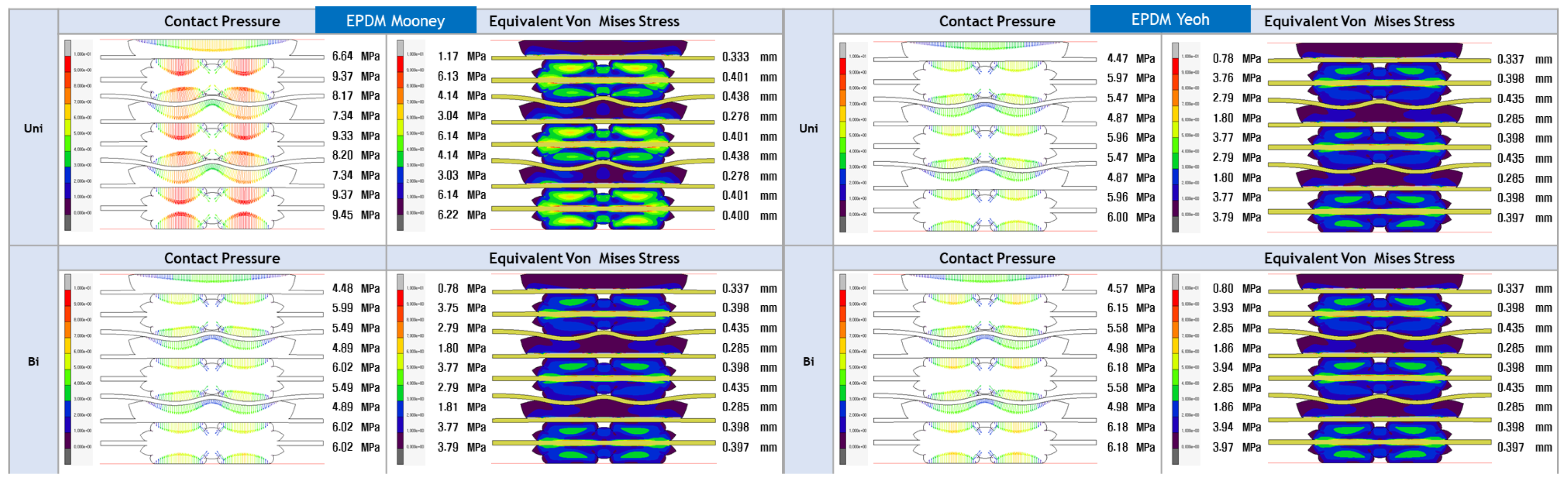
Figure A2.
Contact Pressure and Von Mises Stress modelling visualization considering Ogden and Arruda Boyce Parameters under tensile conditions for PEMFC EPDM gasket material.
Figure A2.
Contact Pressure and Von Mises Stress modelling visualization considering Ogden and Arruda Boyce Parameters under tensile conditions for PEMFC EPDM gasket material.
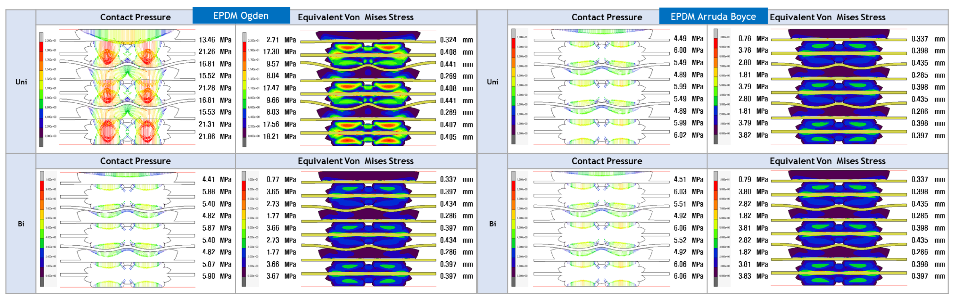
Figure A3.
Contact Pressure and Von Mises Stress modelling visualization considering Gent and Neo Hookean Parameters under tensile conditions for PEMFC EPDM gasket material.
Figure A3.
Contact Pressure and Von Mises Stress modelling visualization considering Gent and Neo Hookean Parameters under tensile conditions for PEMFC EPDM gasket material.
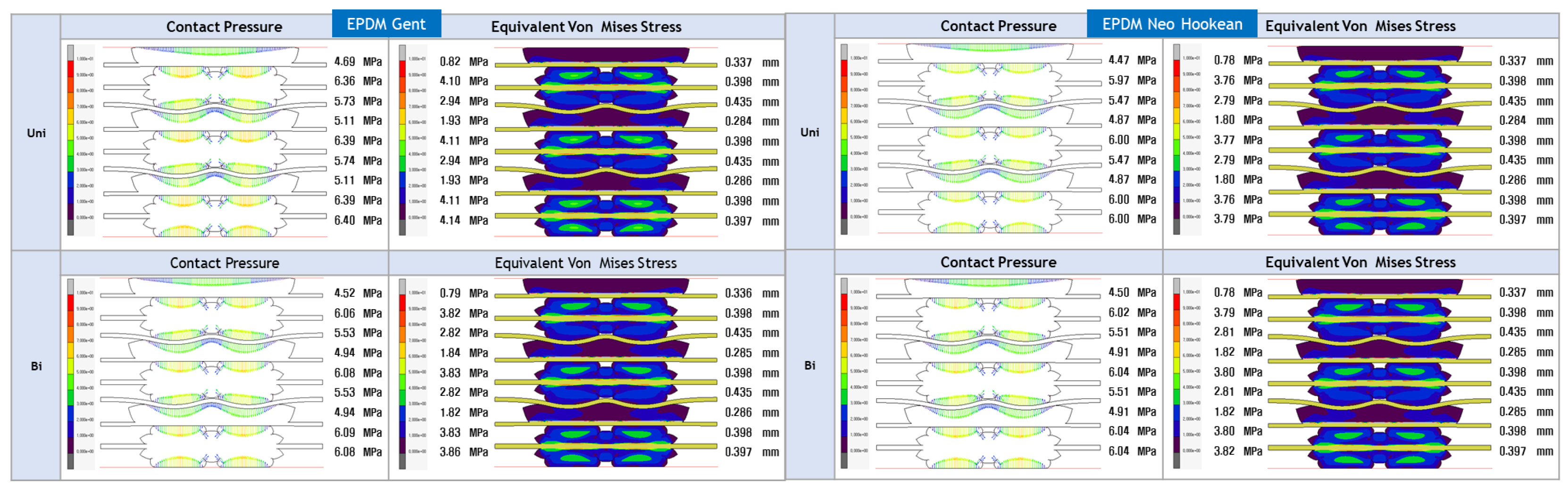
Figure A4.
Contact Pressure and Von Mises Stress modelling visualization considering Mooney and Yeoh Parameters under aging conditions for PEMFC EPDM material.
Figure A4.
Contact Pressure and Von Mises Stress modelling visualization considering Mooney and Yeoh Parameters under aging conditions for PEMFC EPDM material.
Figure A5.
Contact Pressure and Von Mises Stress modelling visualization considering Ogden and Arruda Boyce Parameters under aging conditions for PEMFC EPDM materials.
Figure A5.
Contact Pressure and Von Mises Stress modelling visualization considering Ogden and Arruda Boyce Parameters under aging conditions for PEMFC EPDM materials.
Figure A6.
Contact Pressure and Von Mises Stress modelling visualization considering Gent and Neo Hookean Parameters under aging conditions for PEMFC EPDM materials.
Figure A6.
Contact Pressure and Von Mises Stress modelling visualization considering Gent and Neo Hookean Parameters under aging conditions for PEMFC EPDM materials.
References
- Manoharan, Y.; Hosseini, S.E.; Butler, B.; Alzhahrani, H.; Senior, B.T.F.; Ashuri, T.; Krohn, J. Hydrogen Fuel Cell Vehicles; Current Status and Future Prospect. Appl. Sci. 2019, 9, 2296. [CrossRef]
- John M. T.; Peter P. E.; Peter J. D.; Gari P. O.; Decarbonising energy: The developing international activity in hydrogen technologies and fuel cells, Journal of Energy Chemistry, Volume 51, 2020. [CrossRef]
- Asif J.; Sikander R.; Tanveer I.; Hafiza Aroosa A. K.; Haris M. K.; Babar Azeem, M.Z. Mustafa, Abdulkader S. H.; Current status and future perspectives of proton exchange membranes for hydrogen fuel cells, Chemosphere, Volume 303, Part 3, 2022, 135204, ISSN 0045-6535. [CrossRef]
- Pourrahmani, H.; Siavashi, M.; Yavarinasab, A.; Matian, M.; Chitgar, N.; Wang, L.; Van herle, J. A Review on the Long-Term Performance of Proton Exchange Membrane Fuel Cells: From Degradation Modeling to the Effects of Bipolar Plates, Sealings, and Contaminants. Energies 2022, 15, 5081. [CrossRef]
- Olabi, A.G.; Wilberforce, T.; Alanazi, A.; Vichare, P.; Sayed, E.T.; Maghrabie, H.M.; Elsaid, K.; Abdelkareem, M.A. Novel Trends in Proton Exchange Membrane Fuel Cells. Energies 2022, 15, 4949. [CrossRef]
- Vikas K.; Poornesh K.; Koorata, U. S.; Pranav P.; Soney C. G. Review on physical and chemical properties of low and high-temperature polymer electrolyte membrane fuel cell (PEFC) sealants, Polymer Degradation and Stability, Volume 205, 2022, 110151, ISSN 0141-3910. [CrossRef]
- Yiqing W.; Tahrizi A.; Yilin W.; Ying C.; Eric D. W.; Mark H. E.; Kenneth G. R.; Yong W.; Feng G.; Unmesh M.; Rohil D.; Dylan T.; Hongmei A.; Yuhui Z.;, Krishna K. A comparative study between real-world and laboratory accelerated aging of Cu/SSZ-13 SCR catalysts, Applied Catalysis B: Environmental, Volume 318, 2022, 121807, ISSN 0926-3373. [CrossRef]
- Mohamed, O.A.; Al Khattab, R. Fresh Properties and Sulfuric Acid Resistance of Sustainable Mortar Using Alkali-Activated GGBS/Fly Ash Binder. Polymers 2022, 14, 591. [CrossRef]
- Winter, L.; Lampke, T. Influence of Hydrothermal Sealing on the High Cycle Fatigue Behavior of the Anodized 6082 Aluminum Alloy. Coatings 2022, 12, 1070. [CrossRef]
- Yang, D.; Tan, Y.; Li, B.; Ming, P.; Xiao, Q.; Zhang, C. A Review of the Transition Region of Membrane Electrode Assembly of Proton Exchange Membrane Fuel Cells: Design, Degradation, and Mitigation. Membranes 2022, 12, 306. [CrossRef]
- Ke S.; Yimin W.; Yuhang D.; Hongjie X.; Philip M.; Tobias S.; Katharina B.; Christopher E.; Hannes W. W.; Jens S.; Juergen F.; Kai Z.; Florian W.; Matthias T.; Matthias S.; Albert A. Assembly techniques for proton exchange membrane fuel cell stack: A literature review, Renewable and Sustainable Energy Reviews, Volume 153, 2022, 111777, ISSN 1364-0321. [CrossRef]
- Kim, J. H., Lee, Y. K., and Kim, D. H. Mechanical properties of gasket elastomers for sealing applications. Journal of Applied Polymer Science, 2016, 133(42), 43873. [CrossRef]
- Kurniawan, A., and Shim, Y. Tensile behaviour of silicone rubber gaskets under different temperature conditions. Journal of Applied Polymer Science, 2017, 134(44), 44635. [CrossRef]
- Kang, J., Lee, C., and Kim, J. Tensile and compression properties of soft rubber gaskets used in automotive applications. Polymer Testing, 2015, 42, 42-47. [CrossRef]
- Wang, X., and Li, X. Influence of filler type on the mechanical properties of nitrile rubber gaskets for sealing applications. Journal of Applied Polymer Science, 2017, 134(22), 45217. [CrossRef]
- Chen, J., Yang, J., and Li, Y. Tensile properties and stress relaxation behaviour of silicone rubber gaskets for automotive applications. Polymer Testing, 2015, 47, 90-95. [CrossRef]
- Cheon, K.-M.; Akpudo, U.E.; Kareem, A.B.; Nwabufo, O.C.; Jeon, H.-R.; Hur, J.-W. An FEA-Assisted Decision-Making Framework for PEMFC Gasket Material Selection. Energies 2022, 15, 2580. [CrossRef]
- Olayinka A.; Emblom W.J. Surface roughness of AISI 1010 and AISI 304 of PEMFC bipolar plates with microscale hydroformed capillary channels. Proceedings of the Institution of Mechanical Engineers, Part B: Journal of Engineering Manufacture. 2022; 236(10):1332-1340. [CrossRef]
- Pehlivan-Davis, Sebnem: Polymer Electrolyte Membrane (PEM) fuel cell seals durability. Loughborough University. 2016, Thesis. https://hdl.handle.net/2134/21749.
- Wu, F.; Chen, B.; Yan, Y.; Chen, Y.; Pan, M. Degradation of Silicone Rubbers as Sealing Materials for Proton Exchange Membrane Fuel Cells under Temperature Cycling. Polymers 2018, 10, 522. [CrossRef]
- Jun Feng, Qinglian Zhang, Zhengkai Tu, Wenmao Tu, Zhongmin Wan, Mu Pan, Haining Zhang, Degradation of silicone rubbers with different hardness in various aqueous solutions, Polymer Degradation and Stability, Volume 109, 2014. [CrossRef]
- Lin, C. W., Chien, C. H., Tan, J., Chao, Y. J., and Van Zee, J. W. Dynamic mechanical characteristics of five elastomeric gasket materials aged in a simulated and accelerated PEM fuel cell environment. international journal of hydrogen energy, 2011, 36(11), 6756-6767. [CrossRef]
- Jie Zhang, Yang Hu, Sealing performance and mechanical behaviour of PEMFCs sealing system based on thermodynamic coupling, International Journal of Hydrogen Energy, Volume 45, Issue 43, 2020, Pages 23480-23489. [CrossRef]
- Shen, L., Xia, L., Han, T., Wu, H., and Guo, S. Improvement of hardness and compression set properties of EPDM seals with alternating multilayered structure for PEM fuel cells. International Journal of Hydrogen Energy, 2016, 41(48), 23164-23172. [CrossRef]
- Hu, G., Zhang, P., Wang, G., Zhang, M., and Li, M. The influence of rubber material on sealing performance of packing element in compression packer. Journal of Natural Gas Science and Engineering, 2017, 38, 120-138. [CrossRef]
- Lin, C. W., Chien, C. H., Tan, J., Chao, Y. J., and Van Zee, J. W. Chemical degradation of five elastomeric seal materials in a simulated and accelerated PEM fuel cell environment. Journal of Power Sources, 2011, 196(4), 1955-1966. [CrossRef]
- Pehlivan-Davis, S., Clarke, J., and Armour, S. Comparison of accelerated aging of silicone rubber gasket material with aging in a fuel cell environment. Journal of applied polymer science, 2013, 129(3), 1446-1454. [CrossRef]
- Wang, Z., Tan, J., Wang, Y., Liu, Z., and Feng, Q. Chemical and mechanical degradation of silicone rubber under two compression loads in simulated proton-exchange membrane fuel-cell environments. Journal of Applied Polymer Science, 2019, 136(33), 47855. [CrossRef]
- Chang, H., Wan, Z., Chen, X., Wan, J., Luo, L., Zhang, H., and Tu, Z. (2016). Temperature and humidity effect on aging of silicone rubbers as sealing materials for proton exchange membrane fuel cell applications. Applied Thermal Engineering, 2016, 104, 472-478. [CrossRef]
- Zhou, W.; Wang, C.; Fan, P.; Kuang, Y.; Dong, Z. The Sealing Effect Improvement Prediction of Flat Rubber Ring in Roller Bit Based on Yeoh-Revised Model. Materials 2022, 15, 5529. [CrossRef]
- Lin, A.; Wu, J.; Li, H.; Li, Z.; Su, B.; Wang, Y. Effect of Geometric Error on Friction Behavior of Cylinder Seals. Polymers 2021, 13, 3438. [CrossRef]
- Vieira, J.C.; Mendes, A.d.O.; Ribeiro, M.L.; Vieira, A.C.; Carta, A.M.; Fiadeiro, P.T.; Costa, A.P. FEM Analysis Validation of Rubber Hardness Impact on Mechanical and Softness Properties of Embossed Industrial Base Tissue Papers. Polymers 2022, 14, 2485. [CrossRef]
- Latif R. F. and Shafi Khan N. "Comparative Analysis of Various Hyperelastic Models for Neoprene Gasket at Ranging Strains," 2019 16th International Bhurban Conference on Applied Sciences and Technology (IBCAST), Islamabad, Pakistan, 2019, pp. 179-188. [CrossRef]
- Kim, Y. K., Kim, Y. H., and Kim, J. Y. Development of silicone-based gasket material for PEMFCs. Journal of Power Sources, 2018 284, 289-298. [CrossRef]
- Hu, Y., Zhang, Y., Wang, J., and Liu, Q. A review on proton exchange membrane fuel cell (PEMFC) gasket materials. Journal of Power Sources, 2016, 308, 101-119. [CrossRef]
- Haque, M. E., and Danquah, M. K. A review on the design, selection and optimization of gasket materials for proton exchange membrane fuel cell (PEMFC). Renewable and Sustainable Energy Reviews, 2015, 47, 766-776. [CrossRef]
- Rau, N., and Spiess, W. Fluorinated Ethylene Propylene (FEP) gaskets for proton exchange membrane fuel cells (PEMFCs): An overview. Journal of Applied Polymer Science, 2016, 133(14), 43189. [CrossRef]
- Lee, H. J., and Kim, J. Y. Performance comparison of silicone and fluoropolymer gaskets for proton exchange membrane fuel cells (PEMFCs). Journal of Power Sources, 2018, 389, 157-166. [CrossRef]
- Baker, J. M., and Kim, Y. Dynamic mechanical analysis of an EPDM rubber. Journal of Applied Polymer Science, 2013, 130(1), 378-384. [CrossRef]
- Dubey, N. C., and Bose, S. K. Studies on the thermal and mechanical properties of EPDM and its composites. Polymer Composites, 2015, 36(3), 631-637. [CrossRef]
- Zhang, X., Chen, J., and Han, X. Preparation and properties of EPDM/organic silica hybrid nanocomposites. Journal of Applied Polymer Science, 2015, 132(43), 42076. [CrossRef]
- Hiltunen, M., Nurminen, J., and Ahola, S. Effect of filler type and content on the properties of EPDM rubber compounds. Rubber Chemistry and Technology, 2015, 88(3), 564-576. [CrossRef]
- Chen, J., Zhang, Y., and Han, X. Synthesis and properties of EPDM/organoclay nanocomposites. Journal of Applied Polymer Science, 2013, 128(6), 4117-4123. [CrossRef]
- Fang, Y., Xu, L., and Du, Y. Recent advances in liquid silicone rubber (LSR) materials and applications. Journal of Applied Polymer Science, 2020, 137(3), 48180. [CrossRef]
- Kim, J. H., Lee, H. J., and Kim, K. H. Preparation and mechanical properties of liquid silicone rubber/silicone rubber composite materials. Journal of Applied Polymer Science, 2019, 136(22), 47758. [CrossRef]
- Chiu, H. W., and Li, J. H. Application of liquid silicone rubber (LSR) materials in medical and healthcare products. Polymers, 2020, 12(6), 1019. [CrossRef]
- Li, L., Li, Q., Li, H., and Qiu, Q. A review of liquid silicone rubber (LSR) material and its processing technologies. Polymers, 2019, 11(12), 2288. [CrossRef]
- Sun, X., Li, C., Li, S., and Zhang, X. Properties and applications of liquid silicone rubber (LSR) in 3D printing. Polymers, 2020, 12(10), 1866. [CrossRef]
- Chen, X., and Lin, T. The research progress of liquid silicone rubber (LSR) materials in the field of soft-touch consumer electronics. Journal of Applied Polymer Science, 2019, 136(24), 48005. [CrossRef]
- Zhang, Y., Sun, Y., and Liu, Y. Study on the thermal stability and mechanical properties of liquid silicone rubber (LSR) under high-temperature conditions. Journal of Applied Polymer Science, 2019, 136(12), 46936. [CrossRef]
- Liu, X., Wang, L., and Lu, J. The research progress of liquid silicone rubber (LSR) materials in the field of aerospace. Journal of Applied Polymer Science, 2019, 136(18), 46580. [CrossRef]
- Kang, S. K., Kim, Y. J., and Jeong, J. S. Characterization of FKM and VQM elastomers used in various sealing applications. Journal of Applied Polymer Science, 2019, 136(33), 46699. [CrossRef]
- Lee, J. Y., and Lee, Y. J. Performance comparison of FKM and VQM elastomers in high-temperature sealing applications. Journal of Polymer Engineering, 2017, 37(9), 831–839. [CrossRef]
- Kim, H. J., and Lee, S. H. Evaluation of mechanical and dynamic mechanical properties of FKM and VQM elastomers. Journal of Elastomers and Plastics, 2015, 47(3), 165–173. [CrossRef]
- Zhang, J., Liu, Y., and Chen, X. FKM and VQM elastomers as dynamic seal materials: A review. Journal of Polymer Engineering, 2019, 39(12), 901–913. [CrossRef]
- Oh, J. H., and Kim, J. H. Chemical and thermal stability of FKM and VQM elastomers in high-temperature applications. Journal of Polymer Science and Technology, 2017, 27(2), 145–152. [CrossRef]
- Murea, C.M. Updated Lagrangian for Compressible Hyperelastic Material with Frictionless Contact. Appl. Mech. 2022, 3, 533-543. [CrossRef]
- Ogden, R., Saccomandi, G. & Sgura, I. Fitting hyperelastic models to experimental data. Computational Mechanics 34, 484–502 2004. [CrossRef]
- Kim, B., Lee, S.B., Lee, J. et al. A comparison among Neo-Hookean model, Mooney-Rivlin model, and Ogden model for chloroprene rubber. Int. J. Precis. Eng. Manuf. 13, 759–764 2012. [CrossRef]
- Khaniki, H.B., Ghayesh, M.H., Chin, R. et al. A review on the nonlinear dynamics of hyperelastic structures. Nonlinear Dyn 110, 2022, 963–994. [CrossRef]
- Li, H., Li, J., and Niu, S. A viscoelastic constitutive model for gasket materials under dynamic loading. Journal of Applied Mechanics and Technical Physics, 2019, 60(6), 763-771. [CrossRef]
- Wang, X., Su, J., and Hu, X. A constitutive model for gasket material based on the logarithmic strain rate. Journal of Applied Mechanics and Technical Physics, 2017, 58(2), 244-252. [CrossRef]
- Chen, X., and Liu, Y. Constitutive models for gasket materials considering the nonlinear behaviour of fibre-reinforced rubber composites. International Journal of Non-Linear Mechanics, 2015, 77, 16-25. [CrossRef]
- Zhang, Y., and Jiang, H. A new hyperelastic constitutive model for gasket materials under large deformation. Journal of Mechanics, 2017, 33(6), 797-807. [CrossRef]
- Li, J., Li, H., and Niu, S. An improved constitutive model for gasket materials considering the nonlinear behaviour of rubber composites. International Journal of Mechanics and Materials in Design, 2018 14(1), 53-65. [CrossRef]
- Singla, M.K.; Nijhawan, and P. Oberoi; A.S. Hydrogen fuel and fuel cell technology for cleaner future: a review. Environ Sci Pollut Res 28, 2021, 15607–15626. [CrossRef]
Figure 1.
A breakdown of the PEMFC compartment.
Figure 2.
PEMFC Gasket Material Framework.
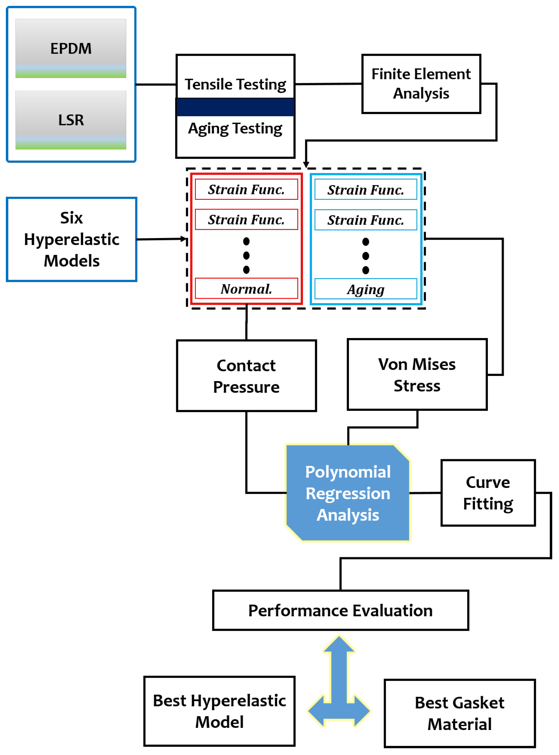
Figure 3.
PEMFC Gasket Experiment (a) Tensile Testing (b) Aging Testing.
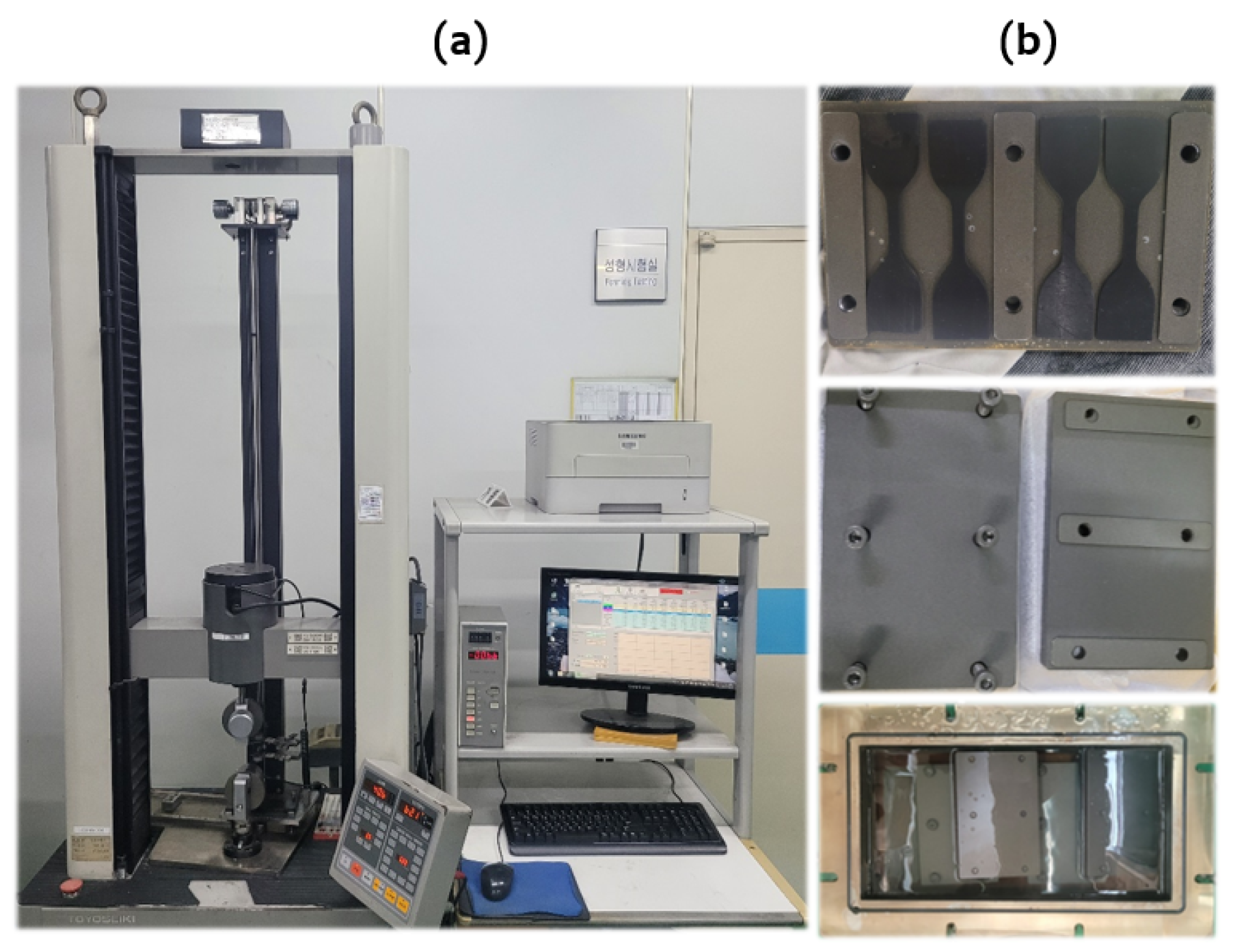
Figure 4.
A cross-section/schematic of the experimental procedure under gasket tensile testing.
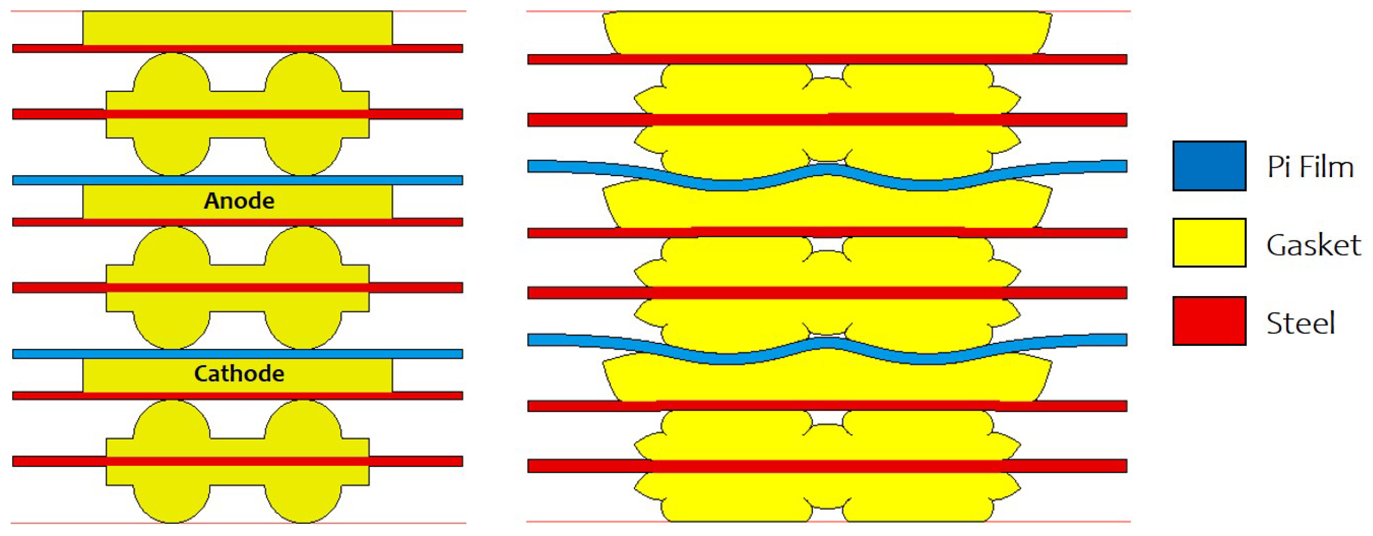
Figure 5.
(a) Stress-Strain curve under biaxial and uniaxial tensile testing at 40% displacement. (b) Stress-Strain curve under aging technique.
Figure 5.
(a) Stress-Strain curve under biaxial and uniaxial tensile testing at 40% displacement. (b) Stress-Strain curve under aging technique.
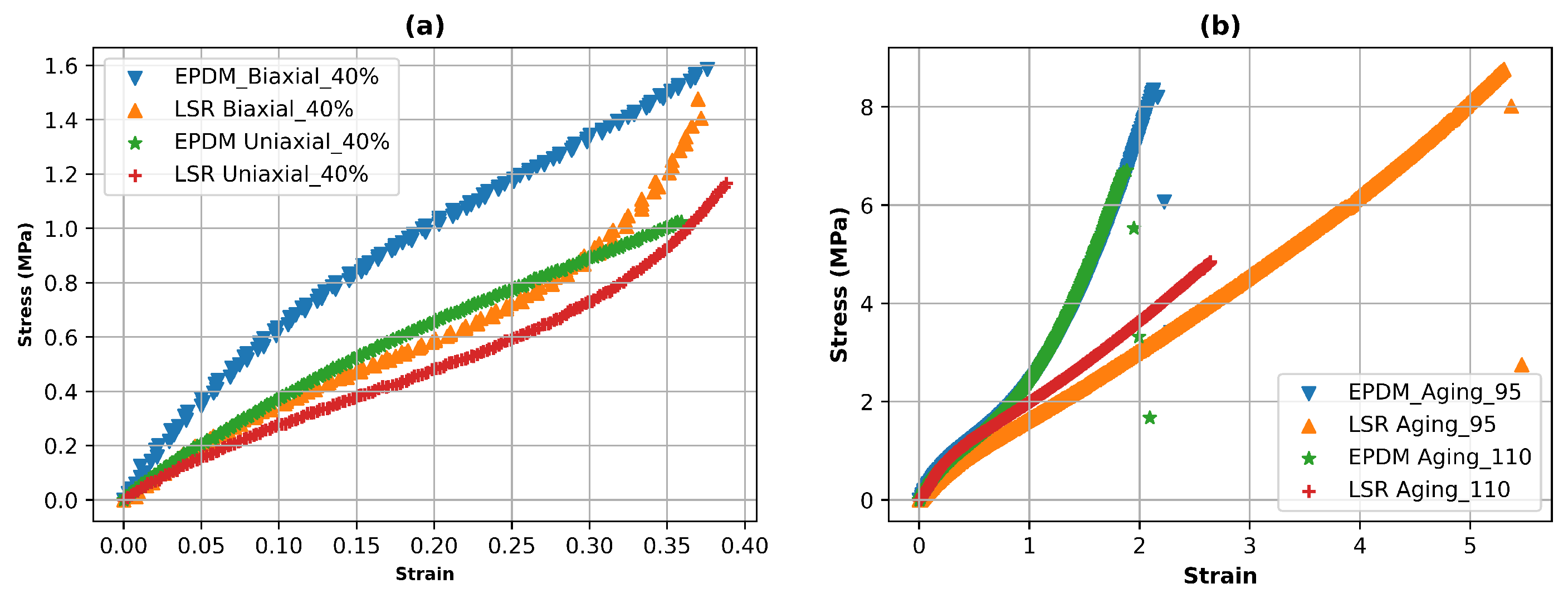
Figure 6.
The FEA process description (a) importing the CAD file in Hypermesh, and exporting the mesh after specifying the drag in Hypermesh, (b) importing the mesh files into MARC, and Setting Geometry & Mesh Model-entity types for models, (c) specifying the boundary conditions, and selecting strain energy function, (d) The curve of the graph is fitted through experimental data, and Turning the interpretation around to check the interpretation results.
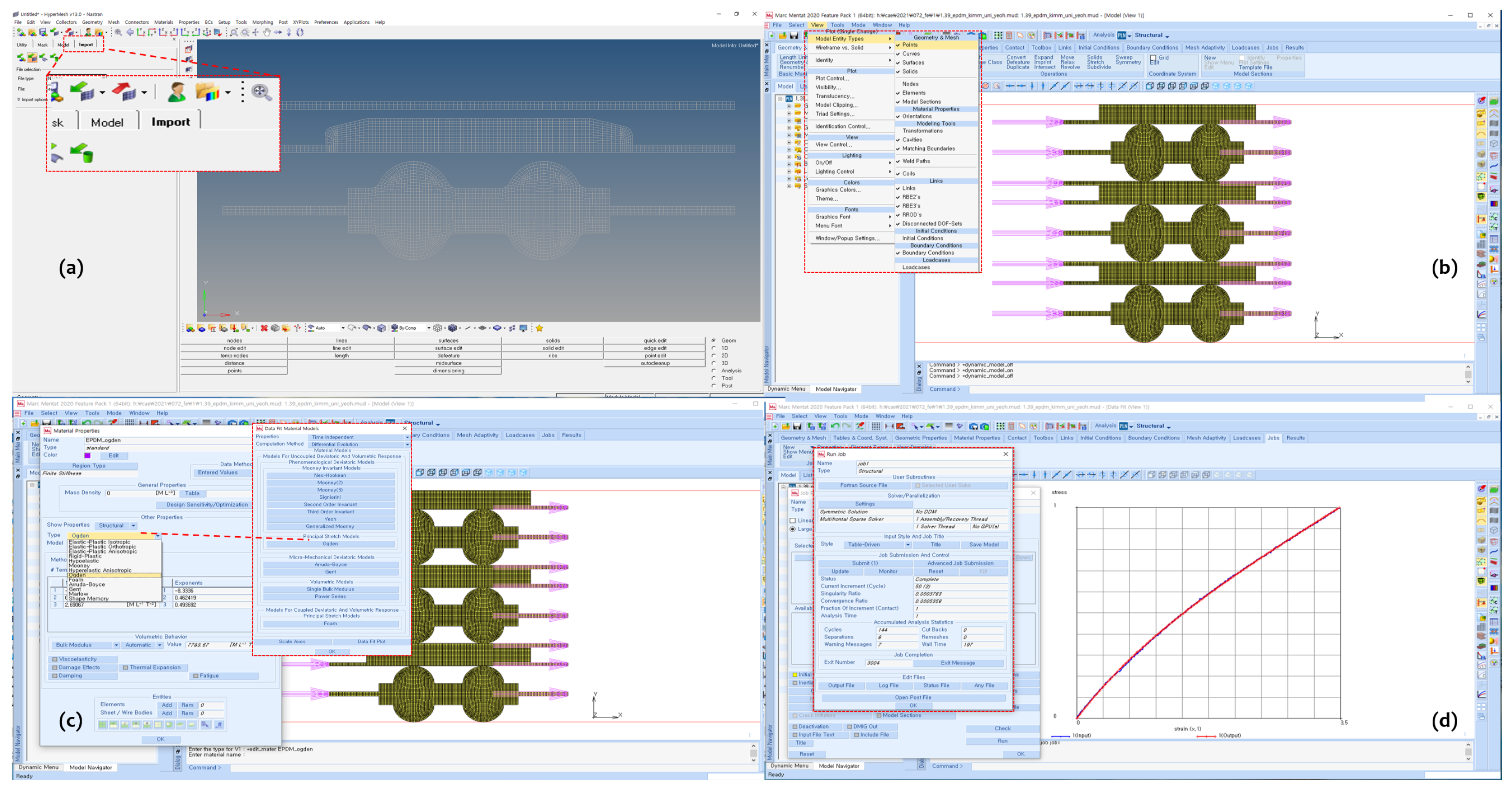
Figure 7.
Contact Pressure and Von Mises Stress modelling visualization considering Mooney Rivlin and Yeoh Parameters under tensile conditions for PEMFC LSR gasket material.
Figure 7.
Contact Pressure and Von Mises Stress modelling visualization considering Mooney Rivlin and Yeoh Parameters under tensile conditions for PEMFC LSR gasket material.
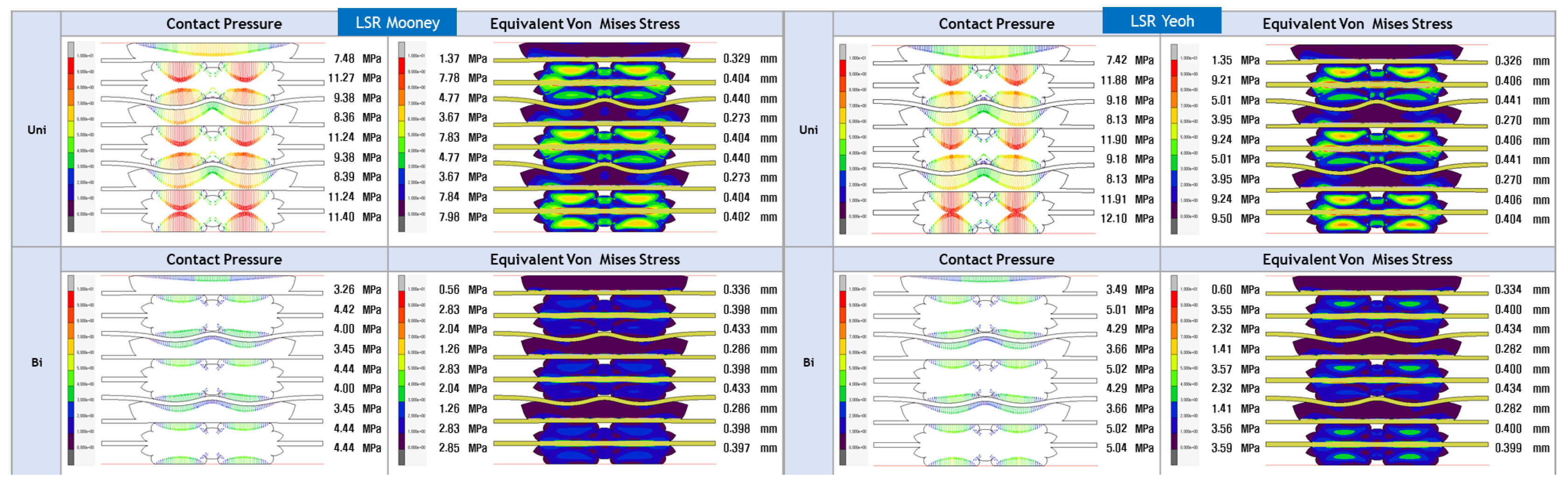
Figure 8.
Contact Pressure and Von Mises Stress modelling visualization considering Ogden and Arruda Boyce Parameters under tensile conditions for PEMFC LSR gasket material.
Figure 8.
Contact Pressure and Von Mises Stress modelling visualization considering Ogden and Arruda Boyce Parameters under tensile conditions for PEMFC LSR gasket material.
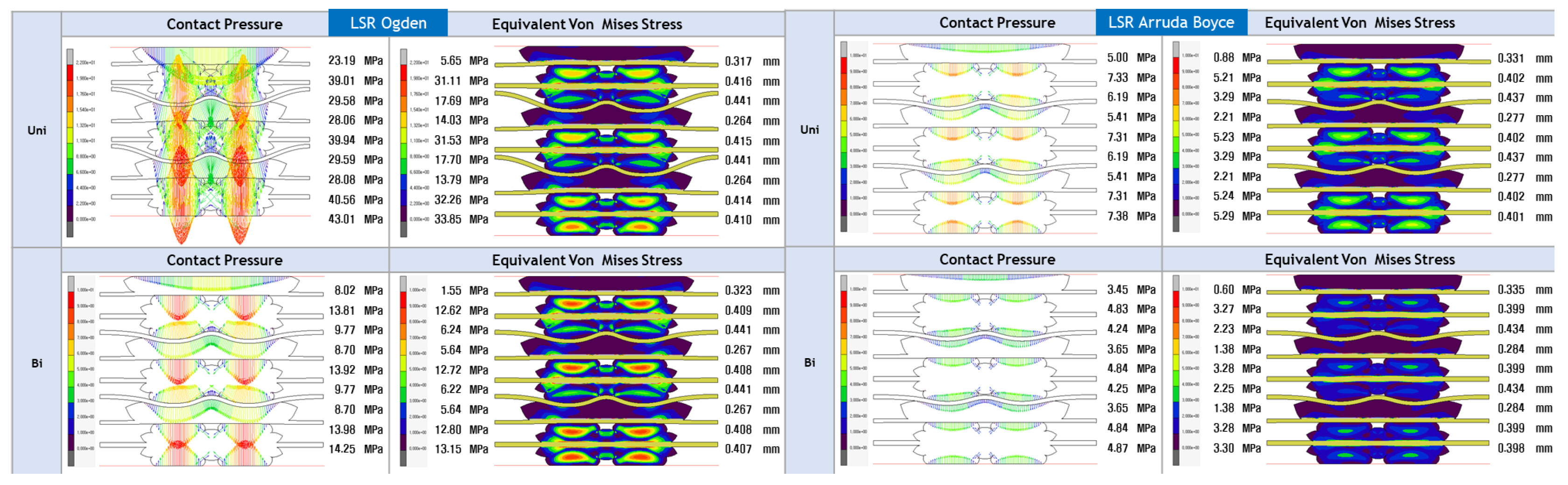
Figure 9.
Contact Pressure and Von Mises Stress modelling visualization considering Gent and Neo Hookean Parameters under tensile conditions for PEMFC LSR gasket material.
Figure 9.
Contact Pressure and Von Mises Stress modelling visualization considering Gent and Neo Hookean Parameters under tensile conditions for PEMFC LSR gasket material.
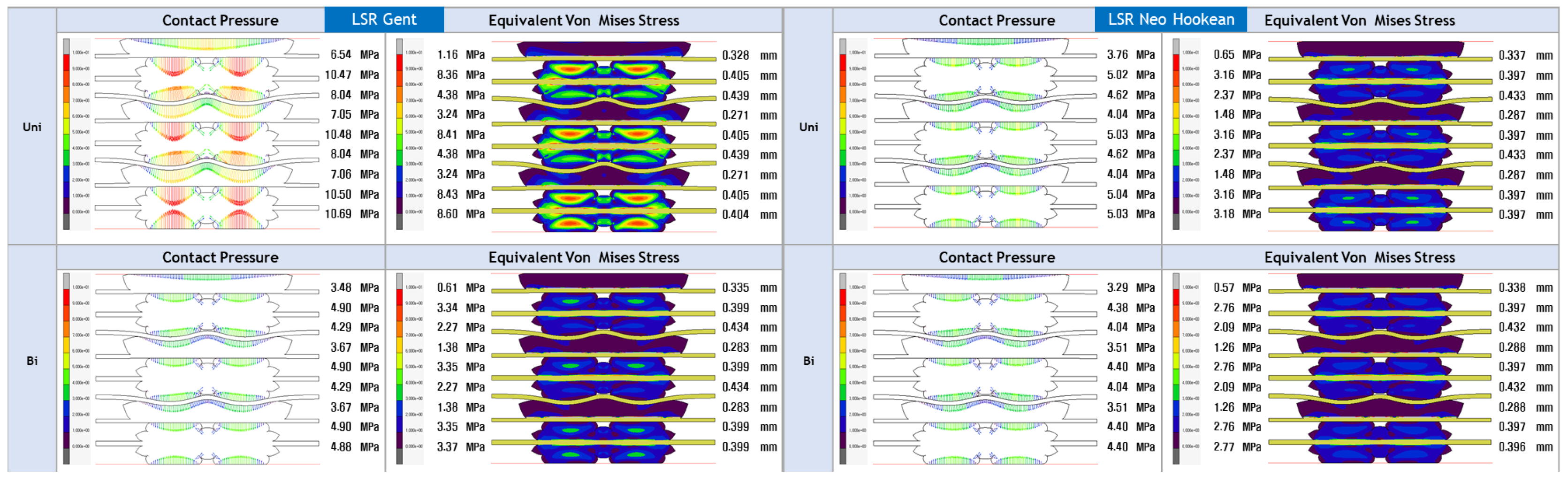
Figure 10.
Contact Pressure and Von Mises Stress modelling visualization considering Mooney and Yeoh parameters under aging conditions for PEMFC LSR gasket materials.
Figure 10.
Contact Pressure and Von Mises Stress modelling visualization considering Mooney and Yeoh parameters under aging conditions for PEMFC LSR gasket materials.
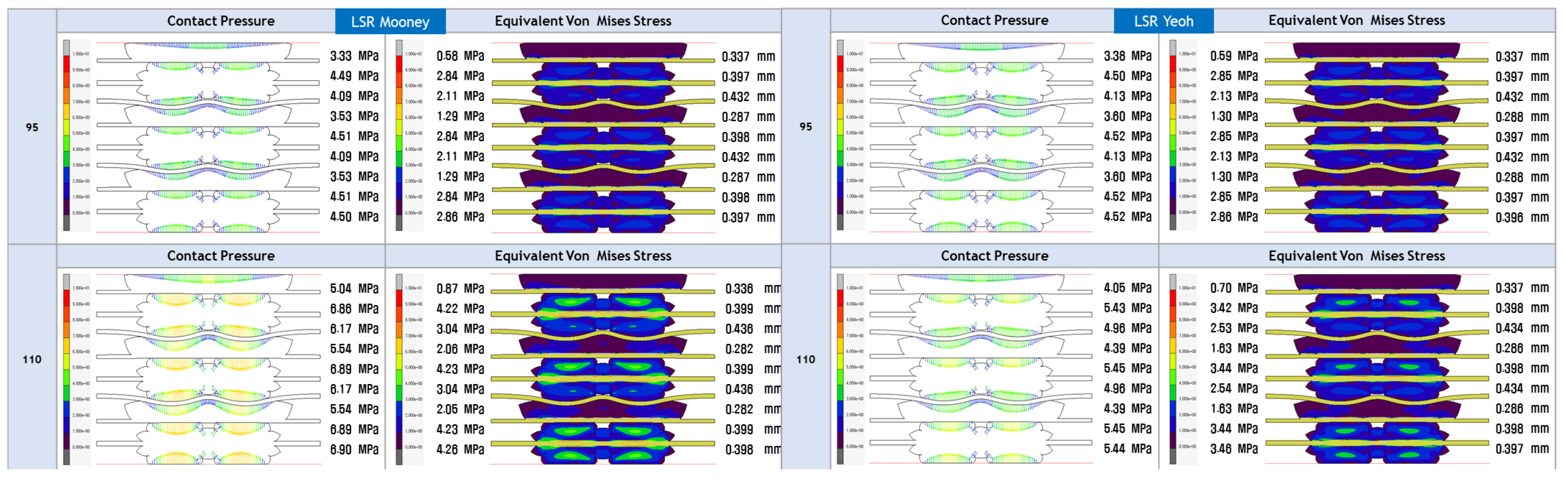
Figure 11.
Contact Pressure and Von Mises Stress modelling visualization considering for Ogden and Arruda Boyce Parameters under aging conditions PEMFC LSR gasket materials.
Figure 11.
Contact Pressure and Von Mises Stress modelling visualization considering for Ogden and Arruda Boyce Parameters under aging conditions PEMFC LSR gasket materials.
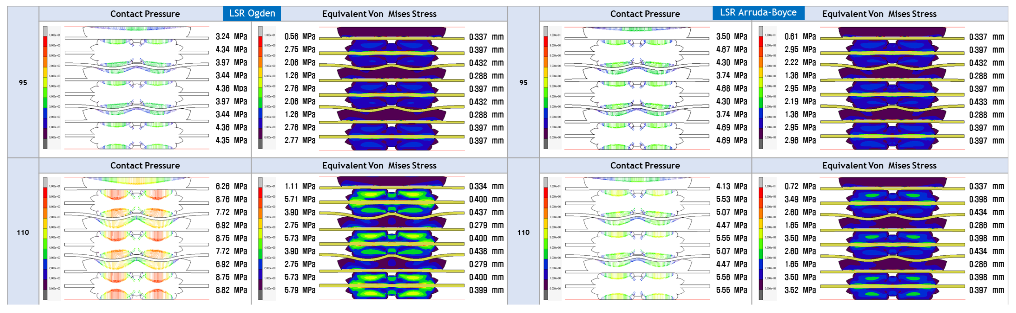
Figure 12.
Contact Pressure and Von Mises Stress modelling visualization considering Gent and Neo Hookean Parameters under aging conditions for PEMFC LSR gasket materials.
Figure 12.
Contact Pressure and Von Mises Stress modelling visualization considering Gent and Neo Hookean Parameters under aging conditions for PEMFC LSR gasket materials.
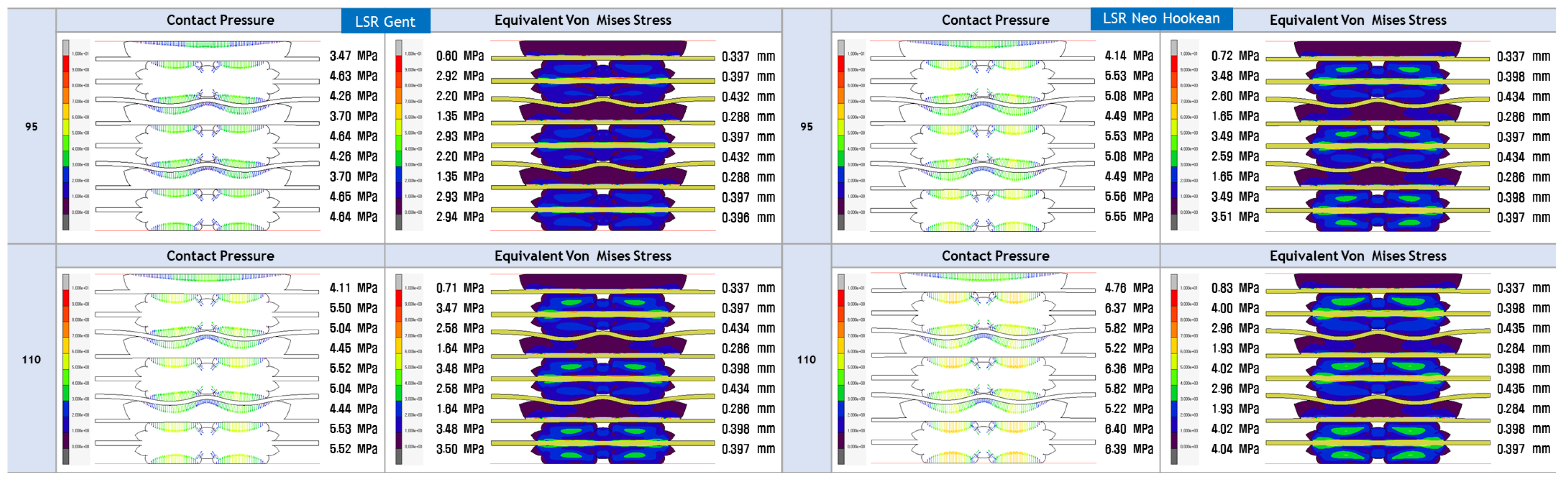
Figure 13.
Contact Pressure output data from FEA modelling considering the multi-hyperelastic models for EPDM and LSR gasket materials.
Figure 13.
Contact Pressure output data from FEA modelling considering the multi-hyperelastic models for EPDM and LSR gasket materials.
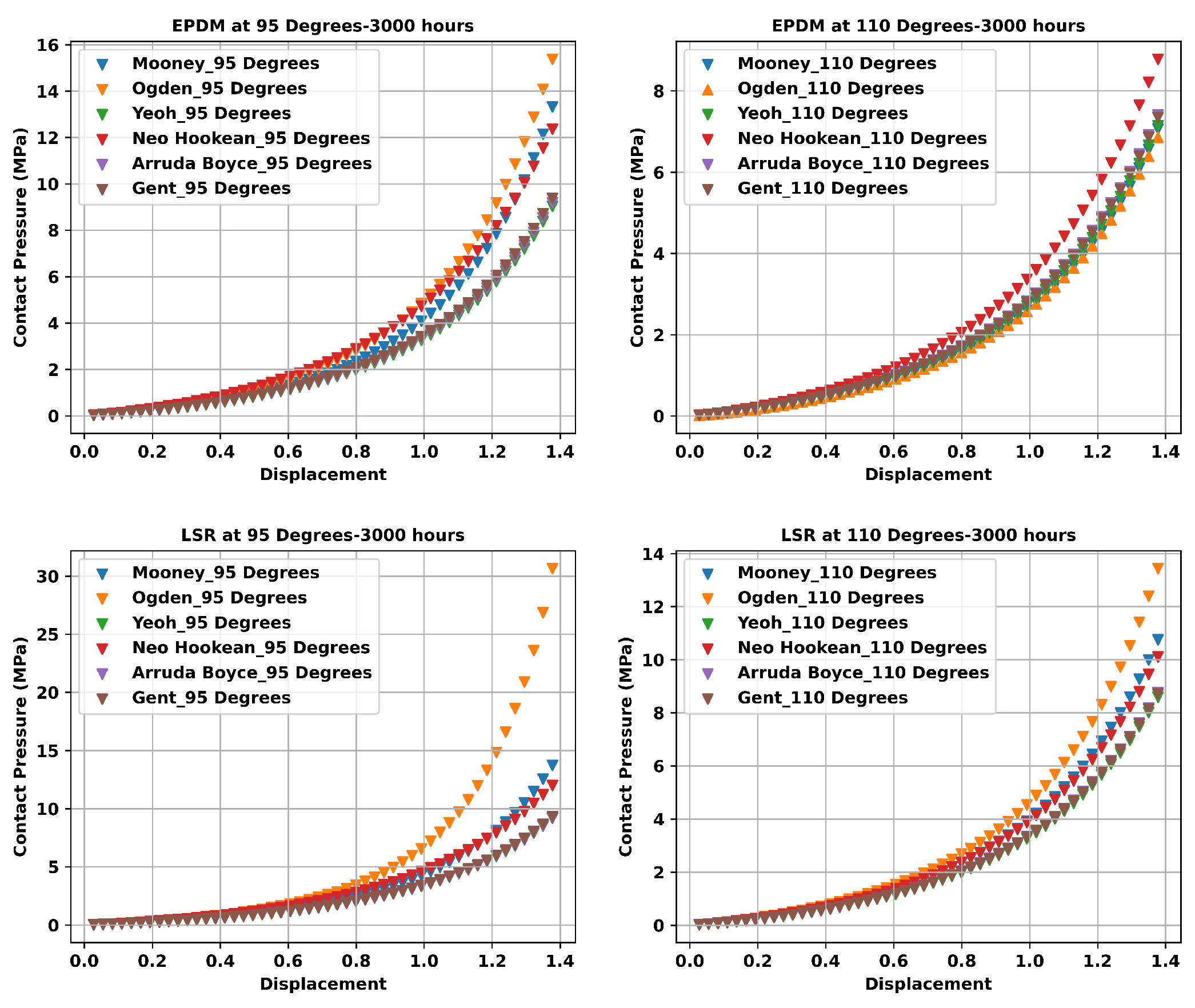
Figure 14.
Von Mises Stress output considering the multi-hyperelastic models at 40% displacement for EPDM and LSR PEMFC gasket material.
Figure 14.
Von Mises Stress output considering the multi-hyperelastic models at 40% displacement for EPDM and LSR PEMFC gasket material.
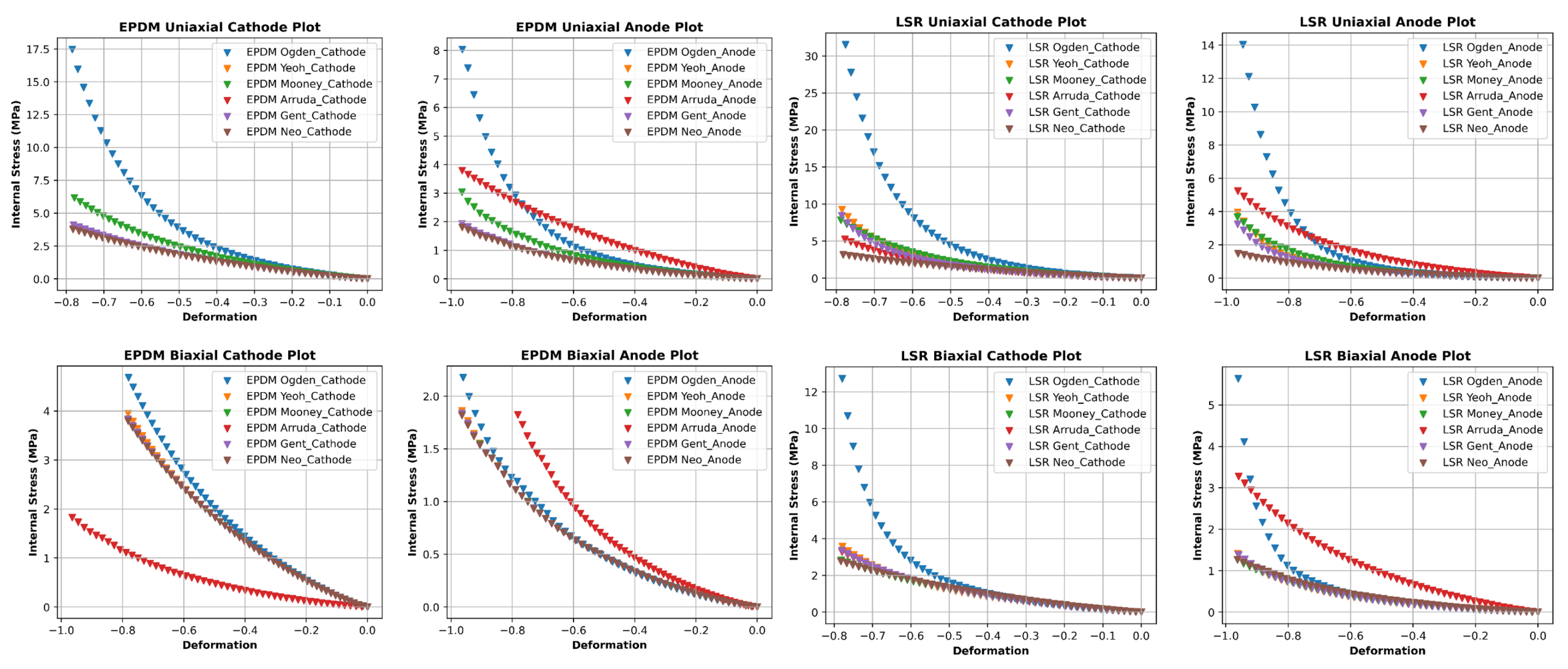
Figure 15.
Curve fitting assessment from multi-hyperelastic models under aging conditions for PEMFC EPDM and LSR PEMFC gasket materials.
Figure 15.
Curve fitting assessment from multi-hyperelastic models under aging conditions for PEMFC EPDM and LSR PEMFC gasket materials.
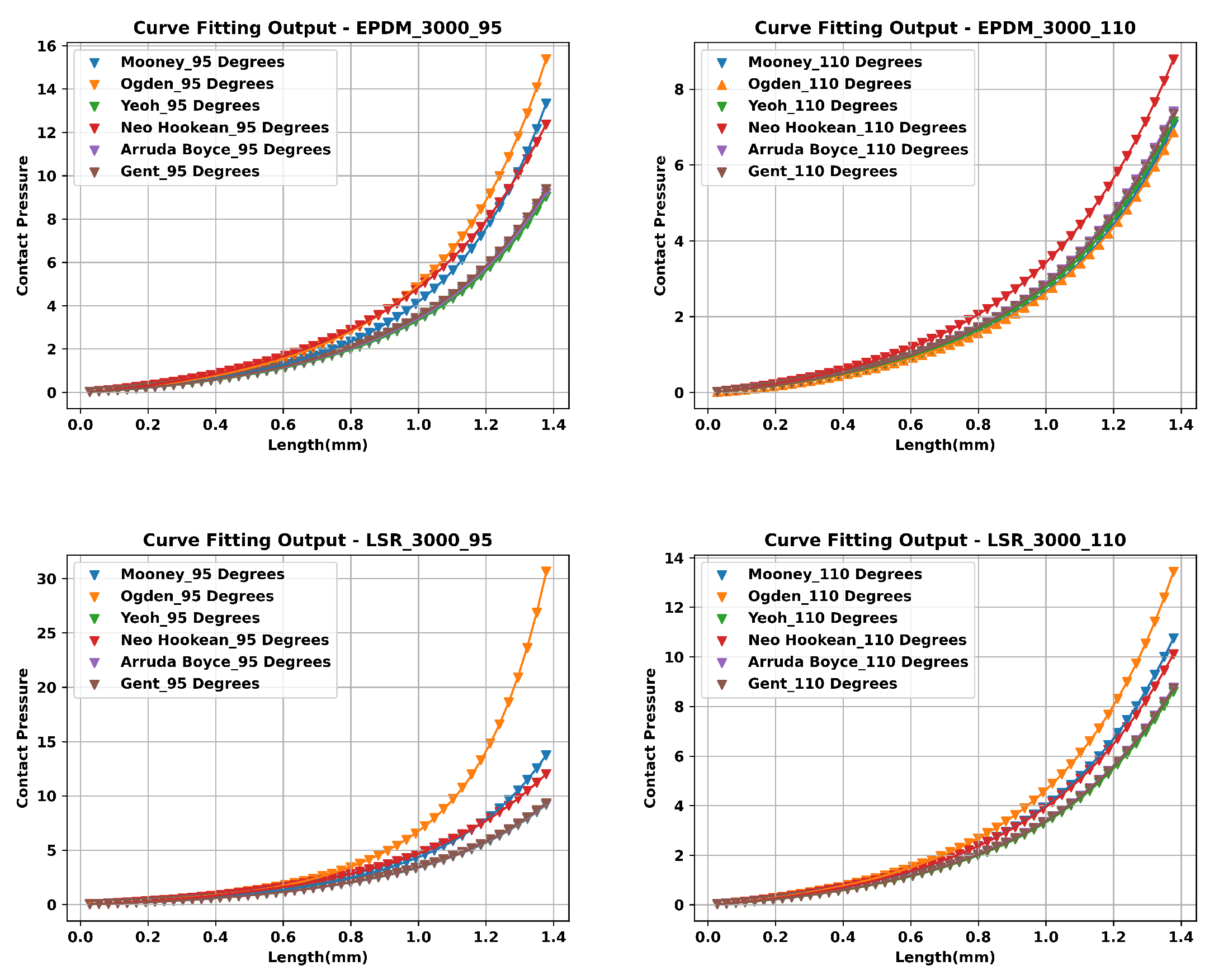
Figure 16.
Curve fitting assessment from multi-hyperelastic models under tensile conditions for PEMFC EPDM gasket material.
Figure 16.
Curve fitting assessment from multi-hyperelastic models under tensile conditions for PEMFC EPDM gasket material.
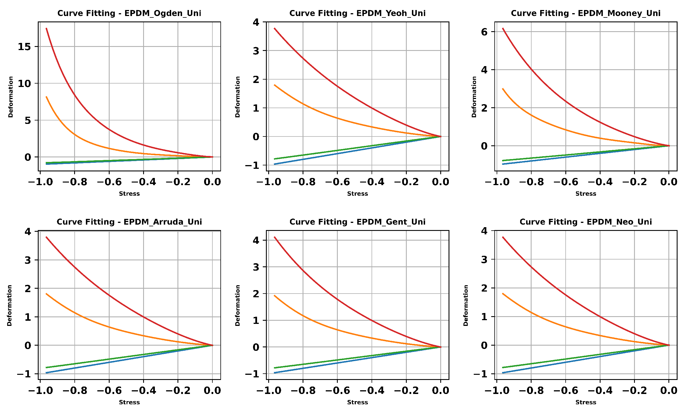
Figure 17.
Curve fitting assessment from multi-hyperelastic models under tensile conditions for PEMFC LSR gasket material.
Figure 17.
Curve fitting assessment from multi-hyperelastic models under tensile conditions for PEMFC LSR gasket material.
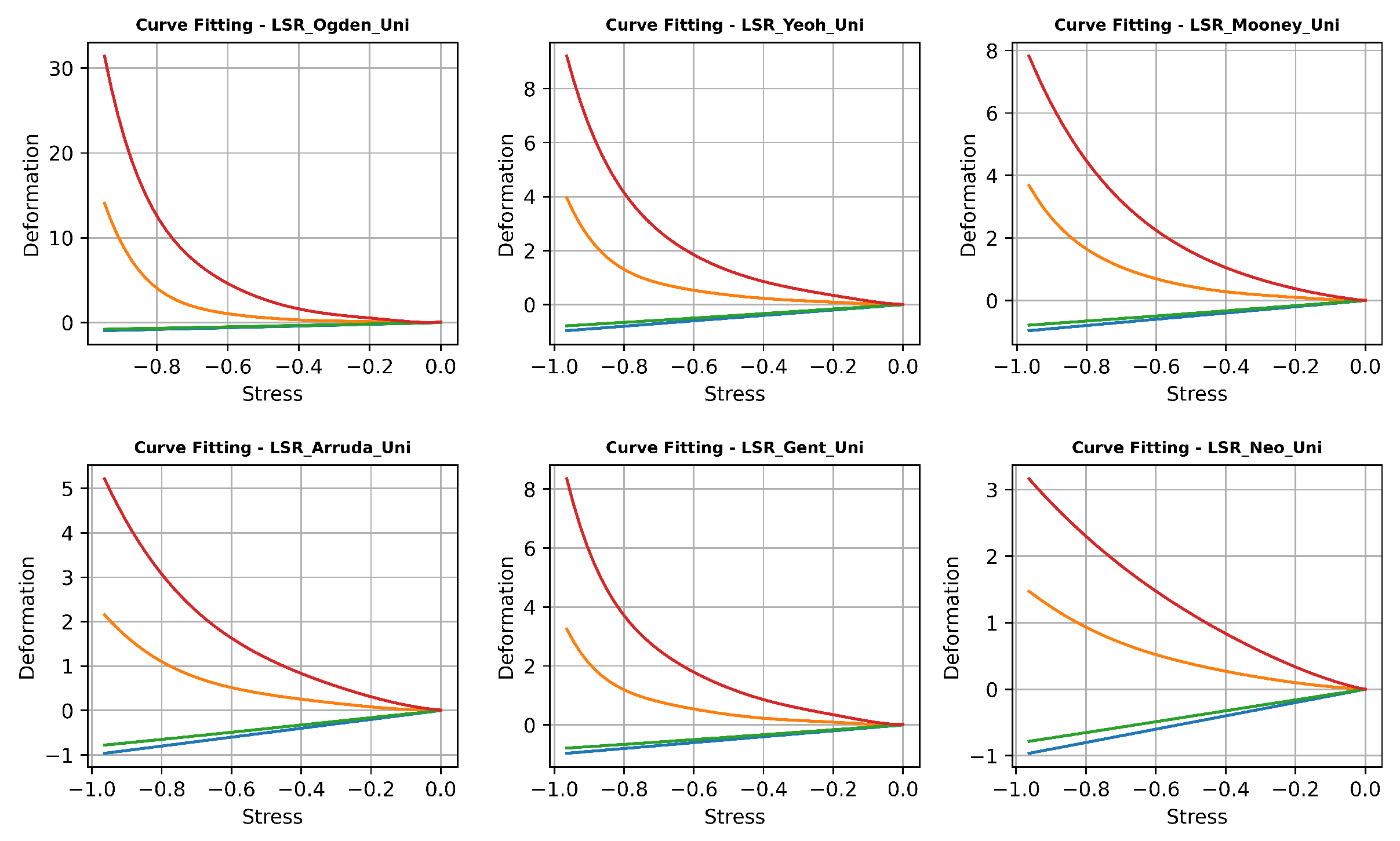
Figure 18.
Regression metrics for EPDM and LSR PEMFC gasket materials considering aging conditions.
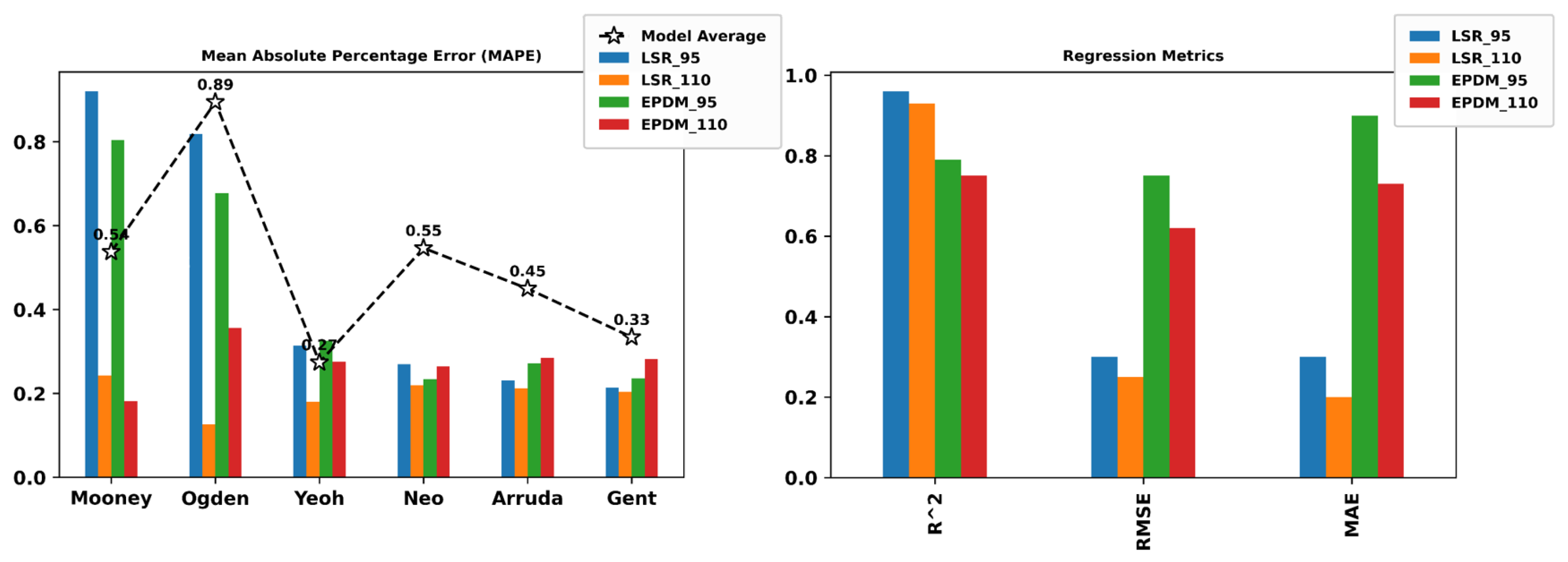
Figure 19.
MAPE Metrics for EPDM and LSR PEMFC gasket materials considering tensile conditions.
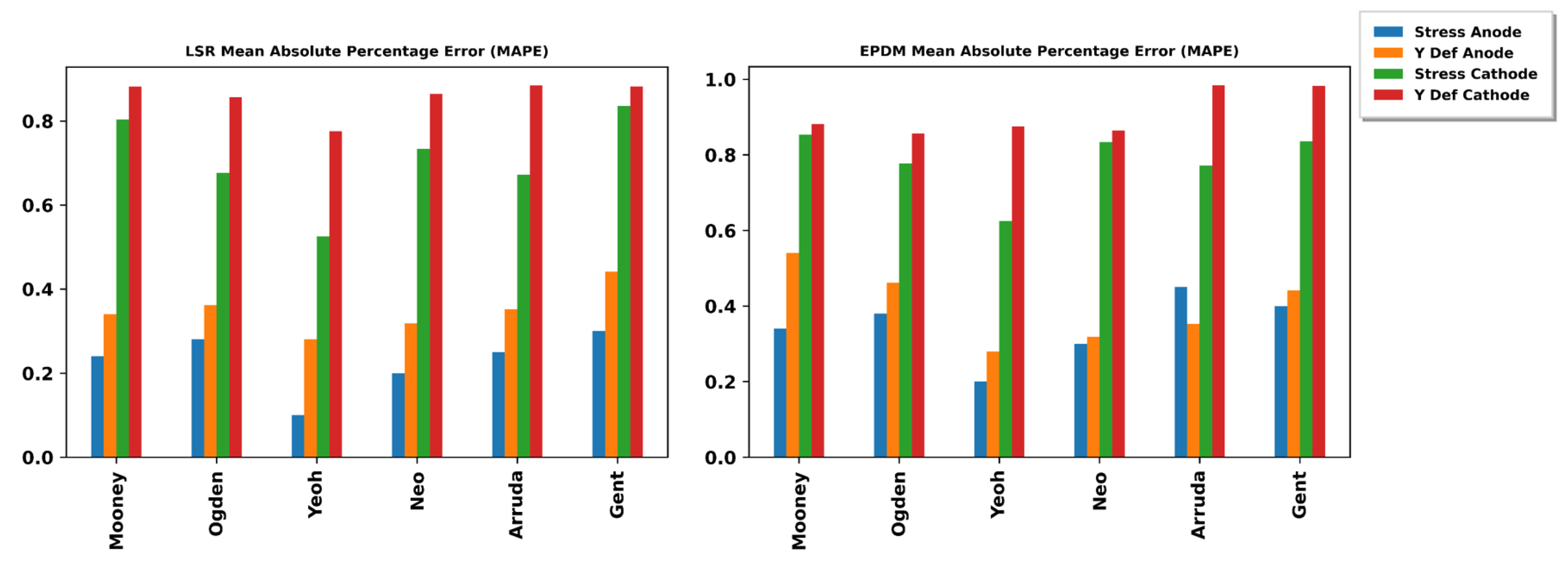
Figure 20.
RMSE and MAE metrics for EPDM and LSR PEMFC gasket materials considering tensile conditions.
Figure 20.
RMSE and MAE metrics for EPDM and LSR PEMFC gasket materials considering tensile conditions.
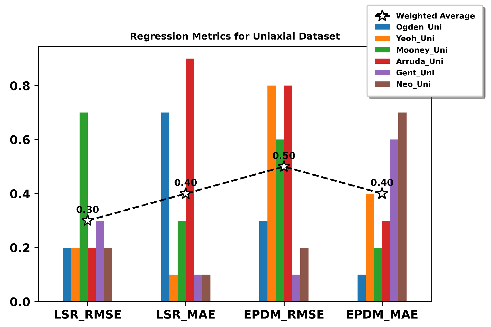

Table 1.
Hyperelastic Model Parameter Values for the selected RLM under dual tensile conditions.
| EPDM | LSR | |||
|---|---|---|---|---|
| Material | Uni | Uni + Bi | Uni | Uni + Bi |
| Mooney Rivlin | = 4.72729e-07 | = 0.646931 | = 4.38303e-08 | = 0.421825 |
| = 0.749213 | = 6.03391e-11 | = 0.50852 | = 6.03424e-11 | |
| = 0.143837 | = 0.00225633 | = 0.422279 | = 0.0257173 | |
| Yeoh | = 0.643052 | = 0.644965 | = 0.479358 | = 0.3965 |
| = 4.30289e-11 | = 5.07886e-08 | = 9.36578e-09 | = 5.4214e-09 | |
| = 2.56582e-08 | = 0.00478875 | = 0.379155 | = 0.0479549 | |
| Ogden | M = -0.209622 E = -8.3336 | M = -2.14506e-05 E = -0.0658951 | M = -0.256473 E = -9.15496 | M = -2.31696e-07 E = -22.8029 |
| M = 0.0826136 E = 0.462419 | M = -1.27328e-05 E = -0.0417977 | M = -0.0108753 E = -9.06697 | M = 0.35083 E = 4.46914 | |
| M = 2.69067 E = 0.493692 | M = 0.939258 E = 2.81305 | M = 0.000119912 E = 24.9996 | M = 5.80656e-05 E = 24.9999 | |
| Neo-Hookean | = 0.643045 | 0.647817 | = 0.538368 | = 0.468658 |
| Arruda Boyce | = 1.26113 | = 1.27561 | = 0.336706 | = 0.492217 |
| = 33.1881 | = 44.4993 | = 1.1 | = 1.84821 | |
| Gent | = 3.80574 | = 3.86915 | = 2.79158 | = 2.39144 |
| = 16.5941 | = 93.0439 | = 4.52345 | = 7.1634 | |
Table 2.
Hyperelastic Model Parameter Values for the selected RLM under aging conditions.
| EPDM | LSR | |||
|---|---|---|---|---|
| Material | ||||
| Mooney Rivlin | = 1.89472e-09 | = 2.69426e-08 | = 0.430276 | = 0.3454 |
| = 0.609227 | = 0.639308 | = 0.0162594 | = 0.33012 | |
| = 0.194325 | = 0.193217 | = 0.016835 | = 0.0323504 | |
| Yeoh | = 0.559296 | = 0.571377 | = 0.475585 | = 0.573542 |
| = 0.026558 | = 0.0237455 | = 0.00318065 | = 0.00468581 | |
| = 0.00294048 | = 0.00393118 | = 2.74909e-13 | = 2.83474e-10 | |
| Ogden | M = -0.664004 E = -3.93474 | M = -0.146388 E = -9.04283 | M = -0.402385 E = -0.686773 | M = -0.563078 E = -3.63278 |
| M = -2.20126e-05 E = -0.0664976 | M = -0.913931 E = -1.97932 | M = 0.626279 E = 2.41526 | M = -0.000248025 E = -0.0898954 | |
| M = 0.0757264 E = 4.91726 | M = -0.000730606 E = -0.0493021 | M = 7.91621e-13 E = 15.2995 | M = 0.328036 E = 2.76844 | |
| Neo-Hookean | = 0.843536 | = 0.817821 | = 0.594852 | = 0.685988 |
| Arruda Boyce | = 0.942321 | = 0.917499 | = 0.972442 | = 1.1427 |
| = 3.61357 | = 3.33084 | = 28.6273 | = 20.9499 | |
| Gent | = 3.54155 | = 3.49077 | = 2.95009 | = 3.50546 |
| = 15.1266 | = 13.6892 | = 119.115 | = 88.4981 | |
* M = Moduli, E = Exponents, Cl = Chain Length, Tm = Tensile modulus, = Max. 1st Invariant
Disclaimer/Publisher’s Note: The statements, opinions and data contained in all publications are solely those of the individual author(s) and contributor(s) and not of MDPI and/or the editor(s). MDPI and/or the editor(s) disclaim responsibility for any injury to people or property resulting from any ideas, methods, instructions or products referred to in the content. |
© 2023 by the authors. Licensee MDPI, Basel, Switzerland. This article is an open access article distributed under the terms and conditions of the Creative Commons Attribution (CC BY) license (http://creativecommons.org/licenses/by/4.0/).
Copyright: This open access article is published under a Creative Commons CC BY 4.0 license, which permit the free download, distribution, and reuse, provided that the author and preprint are cited in any reuse.


