Submitted:
19 July 2023
Posted:
20 July 2023
You are already at the latest version
Abstract
Mercury emissions from small-scale coal-fired boilers are still a serious environmental problem in Poland and the Czech Republic. The publication presents the results of mercury emission tests conducted using five different small-scale coal-fired boilers and five different coal fuels. The research was carried out under laboratory conditions, but also using residential users' heating devices. They covered a wide range of operational parameters, both energy and emission. It was shown that more than 94% of the mercury contained in coal fuel undergoing combustion is emitted into the atmosphere with the volatile products of combustion (including dust), and the amount of emissions is strongly dependent on the original mercury content of the fuel. One solution to the problem of mercury emissions from small-scale coal-fired boilers may be to replace traditional coal with low-emission carbon fuels. The paper shows that mercury emissions from burning such fuels are many times lower than from burning coal. The widespread use of low-emission carbon fuels in individual heating systems in Poland and the Czech Republic would reduce mercury emissions to the atmosphere by up to 90% compared to the current level of emissions generated by individual heating systems in these countries.
Keywords:
mercury emission
; small-scale coal-fired boilers
; low-emission carbon fuel
1. Introduction
Mercury is a rare element that is widely dispersed in nature, with an average concentration not exceeding 0.08 ppm. Owing to its properties, it can occur as a contaminant in any state. In the gas phase, mercury can exist in three forms: elemental mercury vapor (Hg0), volatile compounds (such as Hg2+, mainly HgCl2), and volatile organometallic compounds such as dimethylmercury ((CH3)2Hg). Mercury also contaminates soils, primarily as mercury sulfide (HgS) and mercury oxide (HgO), and less commonly as soluble inorganic compounds (HgCl2 and Hg2Cl2) or organometallic compounds (e.g. (CH3)2Hg). The increase in Hg concentration in soils is mainly due to geological and anthropogenic factors. Mercury can also be found in aquatic environments. Mercury and its compounds enter the water primarily through atmospheric deposition, anthropogenic activities, and mercury migration from the soil. It is important to emphasize that Hg and its compounds are always present in the natural environment, and their concentrations vary depending on the region, climate, and other external conditions, constituting what is known as background Hg levels. Any values exceeding the background levels are considered environmental pollution [1,2].
The estimated global inventory of Hg emissions to the atmosphere from human activities in 2015 was 2,220 Mg, which represents approximately 30% of the total annual Hg emissions released into the atmosphere. An additional 60% of the current global mercury emissions are the result of natural environmental processes, primarily involving the recycling of previously deposited anthropogenic mercury in soils and water. The remaining 10% originates from present-day natural sources such as volcanoes. It is important to note that the global inventory for 2015 does not account for sectors that cannot be accurately quantified. These unquantified sectors may contribute tens to a few hundred tons of Hg to the overall emission inventory [3]. As a result of increasingly intense civilizational development, the emission of Hg from anthropogenic sources has increased over the past decades, causing serious and hazardous contamination of the environment on a global scale, posing a threat to living organisms, including humans. The largest amount of Hg emitted from anthropogenic sources is the result of artisanal gold mining (nearly 40%). The next positions in this ranking are fuel combustion processes (mainly from coal and lignite, approximately 25%), non-ferrous metal smelting (~10%), cement production (~9%), and mercury production processes (~6%) [4].
The structure of mercury emissions from anthropogenic sources in Poland significantly differs from that presented above, primarily because of the practical absence of emissions associated with gold and mercury mining, and the dominant contribution of coal combustion in the domestic energy system, including a substantial share of lignite. Mercury emissions in Poland are estimated to be approximately 11.9 Mg/year in total [5]. The largest share of this emissions comes from the combustion of solid fuels, with an estimated magnitude of approximately 9.1 Mg/year. Emissions from other sectors are primarily attributed to cement production (0.7 Mg/year) and non-ferrous metal smelting (1.1 Mg/year). The Czech Republic reported the total national Hg emissions at the level of 3.48 Mg/year (2010) [6].
In 2022, the Polish electricity production exceeded 175 TWh [7]. Approximately 43% of this production was generated through the combustion of hard coal, whereas approximately 27% was derived from lignite coal [8]. The level of mercury emissions into the atmosphere from coal combustion processes depends on the mercury content of the burned coal, its chemical composition, the type of boiler, mercury speciation in the flue gases exiting the boiler, the content of combustible parts in fly ash, and the composition of the flue gases. The mercury content of coal varies widely depending on the regionalization of the deposit, age, and species. According to national studies, the average mercury content in coal ranges from 0.02 to 0.52 mg/kg in Poland [9] and from 0.01 to 1.0 mg/kg in the Czech Republic [10]. Since Poland has a long border with the Czech Republic (almost 800 km), transboundary transmission of emissions dependent on weather conditions is also important in this regard.
Mercury in coal mainly exists in the form of inorganic compounds, such as HgS, HgO, HgCl2, and others. During coal combustion, these compounds decompose, and at temperatures above 900°C, under the conditions prevailing in the boiler furnace, all mercury from the fuel occurs in the form of elemental mercury vapor (Hg0). Upon cooling the flue gas stream to below 540°C, mercury is partially oxidized to Hg2+, forming volatile compounds such as HgCl2, HgBr2, and others. These compounds exhibit a high affinity for adsorption on the surface of fly ash and unburned coal particles [11].
Mercury emitted from coal combustion is released into the atmosphere in three main forms:
- Hg0(g) – elemental mercury vapor, sparingly soluble in water, capable of persisting in the air for up to two years and capable of long-range transport.
- Hg2+(g) – oxidized form of mercury, forming easily soluble compounds in water that remain in the air for several days to several weeks.
- Hg(p) – mercury bound or adsorbed to fly ash particles, persisting in the atmosphere for several days to several weeks, and spreading only on a local scale [11].
On November 30, 2021, the Commission Implementing Decision (EU) 2021/2326 was published in the Official Journal of the European Union (L 469). This decision establishes the Best Available Techniques (BAT) conclusions for large combustion plants (LCP) in accordance with Directive 2010/75/EU of the European Parliament and of the Council [12]. The BAT conclusions for large fuel combustion installations define the permissible emission levels for various pollutants, including permissible mercury emissions from the combustion of hard coal and lignite. In these installations, mercury emissions can be reduced using different methods, including passive (during flue gas desulfurization in wet scrubbers, selective catalytic reduction (SCR) of nitrogen oxides, flue gas dedusting in electrostatic precipitators, and fabric filters) and active (injection of powdered activated carbon into the flue gas, mercury adsorption on a fixed bed of activated carbon adsorbent, use of impregnated adsorbents, selective coal selection for combustion process, coal enrichment through low-temperature treatment and flotation, and dosing of bromine and iodine salts into the fuel and/or flue gas). However, the new BAT conclusions do not cover small-scale coal and lignite combustion devices, where the aforementioned methods for reducing mercury emissions are not feasible. Such devices are still widely used for heating residential buildings in Poland and the Czech Republic, although their utilization in the Czech Republic is much less common (only about 15% of the heat in households is generated through coal combustion [13]). Currently, they should meet the requirements of Commission Regulation (EU) 2015/1189 of April 28, 2015, implementing Directive 2009/125/EC of the European Parliament and of the Council with regard to ecodesign requirements for solid fuel boilers and emissions [14]. However, they do not cover mercury emissions, and many of the current criteria are not met by the older-type equipment still in use.
Despite numerous programs supporting the promotion of modern heating methods using renewable energy in Poland, approximately 45% of households still use solid fuel heating devices (most commonly, dual-function central heating boilers used for heat production and water heating) [15]. With these devices (excluding biomass), approximately 10 million tons of various grades of coal are burned annually (lignite is currently a marginal fuel used in small-scale devices). It is easy to calculate that the mercury emissions from these devices in Poland, which are not subject to legislative restrictions or technical measures aimed at reducing them, constitute over a dozen percent of mercury emissions from coal combustion for energy purposes. This fact has inspired preliminary studies, and in this article, the authors present the results of their attempt to determine the magnitude of mercury emissions from coal combustion in small-scale devices and propose a simple method for reducing these emissions other than replacing the existing combustion sources.
2. Materials and Methods
2.1. Fuels
The following coal fuel samples were used in the tests conducted:
- three different samples of hard coal (C1, C2 and C3),
- low-emission carbon fuel produced using the pyrolysis process, specially prepared for test purposes for use in residential heating (BC),
- a mixture of hard coal and low-emission carbon fuel with mass shares respectively 0.85:0.15 (CBC).
C1, C2 and C3 coals were typical coal fuels sold commercially for residential heating use. The other two fuels (BC and CBC), on the other hand, are specially developed low-emission carbon fuels developed by Polish fuel producers with the participation of the Institute of Energy and Fuel Processing Technology. The main benefit of using these fuels is a significant reduction in emissions of polycyclic aromatic hydrocarbons (including benzo(a)pyrene) and particulate matter (including PM10) [16,17]. However, the research presented in this publication focuses on assessing the possibility of reducing mercury emissions through their use in low-power heating devices still in use in Poland and the Czech Republic (but also in many other countries).
2.2. Boilers
The combustion of the fuels listed above was carried out using a variety of small-scale coal-fired boilers. The following boilers with different designs and operational characteristics were selected for the planned research:
- A manually fueled boiler with a nominal power of 12 kW (boiler no. 1 – B1).
- A manually fueled boiler with a nominal power of 15 kW (boiler no. 2 – B2).
- Boilers with automatic fuel feeding and a nominal power of 100 kW (boiler no. 3 – B3).
- A boiler with automatic fuel feeding and a nominal power of 24 kW (boiler no. 4 –B4).
- A boiler with automatic fuel feeding and a nominal power of 150 kW (boiler no. 5 – B5).
Experiments using boilers no. 1 and no. 2 were conducted at the test facility of the Institute of Energy and Fuel Processing Technology. Boilers no. 3-5 were tested at their operating locations. The following is a brief description of the aforementioned boilers.
2.2.1. Boiler no. 1 (B1)
This is a low-temperature steel boiler designed for open systems and adapted for burning hard coal of the pea size assortment. The boiler body is made of steel plates. Inside the body there is an ash chamber, a grate, a combustion chamber, a fuel loading chamber and flue ducts. The boiler is also equipped with an ash door, a fuel loading door and flue ducts cleaning door. The combustion chamber is equipped with a burner nozzle. Air was supplied to the boiler through an adjustable damper located on the loading door. The air passing through the grate participated in the combustion process. Additionally, air was supplied to the combustion chamber by the ash chamber. Periodic ash removal was performed using a scraping mechanism. The tested boiler meets the emission criteria of Class 5 of the EN 303-5:2012 standard and ecodesign requirements (except for the energy efficiency criterion) [14]. Its view is presented in Figure 1.
2.2.2. Boiler no. 2 (B2)
This boiler is a representative of a type series of low-temperature, steel water boilers, designed for open systems, adapted for combustion of hard coal of nut type (basic fuel) and hard coal of pea type. In these units, fuel is loaded into a loading chamber terminated with a water grate. The loading chamber is closed by a charging door. A secondary air damper is located on the charging door. Above the charge door there is a cleanout door for access to the heat exchanger. A stream of primary air is fed into the combustion chamber by a blowing fan located on the upper wall of the boiler. The flue gases, after passing through the flue-water heat exchanger, pass through the boiler's flue to the chimney. The boiler is also equipped with a mechanical grate rake. The boiler is insulated with mineral wool, covered with painted steel sheet. The tested device does not meet the emission criteria of Class 5 of the EN 303-5:2012 standard and ecodesign [14]. Its view is presented in Figure 2.
2.2.3. Boiler no. 3 (B3)
It is a boiler with automatic fuel feeding and retort burner. This boiler belongs to a series of low-temperature, steel water boilers, designed for open systems, adapted for burning hard coal of the pea-sort. In this unit, fuel is poured into a hopper closed with a steel door, located on the side of the boiler over a screw feeder driven by a gearmotor. The feeder moves successive portions of fuel from the hopper to the retort burner, located in the combustion chamber. The retort burner is made of cast iron in the shape of a truncated cone with drilled holes and tabs to the inside forming a screw line. In addition, a cast iron deflector is mounted above the burner. The combustion chamber is lined with ceramic plates and is closed with an insulated door. A stream of air is fed to the burner in the combustion chamber by means of a blowing fan. A feed water muffle is located in the upper rear part of the boiler. The return water muffle is located at the lowest point of the boiler. The boiler has a vertical plate heat exchanger. The flue gases, after passing through the heat exchanger (flue-water), pass through the boiler's flue to the chimney. Flue gas swirlers are installed in the second and third pass of the heat exchanger. Regulation of heat output is carried out by an electronic temperature controller. This regulator controls the operation of the water circulation pump, hot water pump, floor heating pump, circulation pump, air blower (fan) and fuel feeder. The boiler is insulated with mineral wool covered with painted steel sheet. This boiler, when properly operated, meets the criteria of Class 5 of the EN 303-5:2012 standard and ecodesign [14]. Its view is presented in Figure 3.
2.2.4. Boiler no. 4 (B4)
It is a boiler with automatic fuel feeding and a retort burner with a screw feeder, adapted for burning hard coal of the pea-sort. It is designed for open system water central heating systems. In addition to burning coal in automatic mode, this boiler also allows burning other fuels in manual loading mode. The tested boiler at the time of the study was already a far out-of-service device. As a new device, it met the criteria of Class 5 of the EN 303-5:2012 standard and ecodesign [14]. However, it did not meet these criteria at the time of the presented research. Its view is presented in Figure 4.
2.2.5. Boiler no. 5 (B5)
This is a boiler with automatic fuel feeding and retort burner. This boiler belongs to the low-temperature steel water boilers, designed for open systems, adapted for burning hard coal of the pea-sort. In this unit, fuel is poured into a hopper closed with a steel door, located on the side of the boiler over a screw feeder driven by a gearmotor. The feeder moves successive portions of fuel from the hopper to the retort burner located in the combustion chamber. The combustion chamber is closed with a door. A circular ceramic deflector is placed above the burner. A stream of air is fed to the burner in the combustion chamber by means of a blowing fan. A feed water muffle is placed in the upper part of the boiler exchanger. The return water muffle is located at the lowest point of the boiler exchanger. The boiler has a plate heat exchanger. The flue gases, after passing through the flue-water heat exchanger, pass through the boiler's flue to the chimney. Regulation of the boiler's heat output is carried out by an electronic temperature controller. This regulator controls the operation of the feeder, blower fan, central heating and hot water pumps. The boiler is insulated with mineral wool covered with painted steel sheet. The tested boiler, when operated properly, meets the criteria of Class 5 of the EN 303-5:2012 standard and ecodesign [14]. Its view is presented in Figure 5.
The small-scale coal-fired boilers selected for the study represent the variety of designs used for heat and hot water production in residential heating in Poland and the Czech Republic.
2.3. Experiments
The tests presented in this publication include coal fuel combustion tests conducted according to the scheme shown in Table 3.
2.3.1. Laboratory tests
Energy and emission tests of the combustion of hard coal (B1/C1 and B2/C2) and low-emission carbon fuel (B2/BC), and thus with the use of boilers with manual fuel feed, were carried out on a test stand at the Laboratory of Combustion Technologies and Power Generation operating within the structure of ITPE (Zabrze, Poland). These tests included two feeds of portions of fuel into the boiler each time. The weight of the fuel for both intakes was the same and was based on the provisions of the PN-EN 303-5+A1:2023-05 standard [18] and the calorific value of the fuel in question. It shows that the amount of fuel loaded into the boiler must be sufficient for at least 4 h of its operation at nominal power. First, an adequate layer of embers was pregenerated in the boiler. Then a weighed portion of fuel was poured onto the embers so as to ensure the required test duration, during which the flue gas composition was measured: O2, CO2, CO, NO, SO2, and the content of dust and total organic carbon (TOC). Flue gas collection for the determination of dust and TOC was performed using a system consisting of a probe (installed in the chimney) connected to a heated dust separator, a cooler, a tubing system with sorption material (XAD-2 resin and activated carbon) and a gas aspirator. Collection of flue gases for analysis was conducted based on the laboratory's accredited technical procedure. The dust concentration was determined using the gravimetric (filtration) method in accordance with the internal procedure of the Laboratory of Combustion Technologies and Power Generation Q/LS/02/D:2018 and PN-Z-04030-7 "Protection of air purity. Testing of dust content" and PN-EN 13284-1 "Emissions from stationary sources. Determination of dust mass concentration in the low range. Part 1: Manual gravimetric method". In addition, boiler energy parameters such as flue gas temperature, boiler inlet and outlet water temperatures, water flow and chimney draught were recorded during the tests.
A mobile set of SIEMENS analyzers was used to measure the composition of the exhaust gas (Figure 6). The set included ULTRAMAT 23 analyzers enabling the measurement of CO in the range of 0-5%, CO2 in the range of 0-25%, SO2 in the range of 0-1000 ppm, and NO in the range of 0-1000 ppm. These analyzers allow measurement using the reference NDIR method. O2 concentration in the gas was measured using an analyzer of the OXYMAT 61 type, which operates on the basis of a reference method using the phenomenon of paramagnetism. This analyzer has a range of 0-25% O2. Concentrations of O2, CO2, CO, NO, SO2 were determined based on the PN-ISO 10396:2001 standard "Emissions from stationary sources. Sampling for automatic measurement of concentrations of gaseous components".
After the combustion test of a given fuel was completed, the generated bottom ash was secured and transferred to the laboratory for determination of mercury content. The mercury content of both the fuel and bottom ash samples was determined using the cold vapor atomic absorption amalgamation (CVAAS) method, with an MA-2 analyzer from Nippon Instruments Corporation.
2.3.2. Field trials
Energy and emission tests of the combustion of hard coal (B3/C3, B4/C3 and B5/C3) and low-emission carbon fuel (B3/CBC, B4/CBC and B5/CBC), and thus with the use of boilers with automatic fuel feeding, were carried out at individual users in various locations in Poland. At each location, several weeks prior to the start of the tests, the boilers operated continuously burning previously supplied CBC fuel. C3 hard coal was delivered to the site on the day of the measurements, in sufficient quantity for several hours of boiler operation.
The boiler operator at each test site was informed of the test day. Each time, the operator was asked to conduct a thorough cleaning of the boiler on the day before the test day, and then conduct CBC fuel combustion in the boiler in accordance with past practice. Each time the ITPE/VŠB measurement group arrived on site, the boiler was extinguished for about 30 minutes. During this time, the measuring apparatus was assembled, the boiler's ash chamber was cleaned, and a continuous fuel feeding test was performed, which ultimately allowed the determination of the fuel flow fed to the combustion. The boiler was then fired up and the boiler's operating conditions were stabilized over a period of 1.5 to 2 h. The operating conditions of the boiler were set by the local staff each time, without any interference or comments from those in the measurement group.
The actual testing began with the re-cleaning of the boiler's ash chamber. This was followed by an energy-emission test during the combustion of CBC fuel. The combustion test of this fuel was completed by selecting a sample of bottom ash from the boiler's firebox. Then the CBC fuel was selected from the boiler hopper, the remaining fuel was removed from the feeding system and the boiler was carburized with C3 fuel.
After the C3 fuel was fed to the retort burner, the boiler was fired up and the boiler operating conditions were stabilized over a period of 1.5 to 2 h for the same settings at which the CBC fuel combustion was tested, i.e. fuel feed time, fuel feed interval time and fan blowing power percentage setting.
The actual testing began by cleaning the ash chamber of the device again. This was followed by an energy-emission test during the combustion of C3 fuel. The test was completed by selecting a sample of the bottom ash from the boiler's combustion chamber.
The furnace solid waste samples were secured and transferred to the ITPE laboratory for determination of Hg content.
For the field measurements, measuring equipment analogous to that used in the laboratory studies was used. Only TOC emissions were not measured during these experiments. The measuring equipment used during the boiler tests by ITPE employees meets the requirements of PN-EN 303-5 "Measuring Instruments and Methods of Measurement."
3. Results
The basic energy and emission parameters of the experiments conducted are shown in Table 4 and Table 5.
Table 6 presents the results of the calculations based on the mercury analyses performed for the fuels tested and the bottom ash produced during the combustion tests. It was assumed that the amount of mercury fed with air into the combustion process is negligible.
4. Discussion
Combustion tests of various coal fuels in boilers of different designs covered a wide range of operating parameters, both energy and emissions. The flux of coal fuels burned ranged from 2 to 12.2 kg/h, with an equally wide range of boiler efficiencies obtained – 67.6-88.5%. It should be noted here that the boilers tested in the laboratory (boilers with manual fuel feeding) operated at slightly higher than nominal relative thermal loads, while the boilers tested at individual users operated at very low relative thermal loads – <45% of nominal power.
The test results presented in this article show that the amount of emissions of pollutants limited by the criteria of the PN-EN 303-5+A1:2023-05 standard [16] and the ecodesign [14], namely carbon monoxide, nitrogen oxides, dust and organic substances, depends mainly on the design and operating conditions of the device in which the specific solid fuel is burned. A detailed analysis of this issue, is beyond the scope of this publication, although Table 4 and Table 5 clearly show the differences in these parameters from one test to another. However, there is a group of pollutants emitted into the atmosphere, for which the amount of emissions depends primarily on the quality of the fuel burned. These pollutants include sulfur oxides and mercury, whose emissions depend primarily on the combustible sulfur and mercury content of the fuel being burned.
Figure 7 shows the dependence of mercury emissions from the tested heating equipment on the mercury content of the fuel being burned. Based on the data presented, it is clear that mercury emissions with volatile combustion products are very strongly related to its initial content in the fuel fed to the boiler (correlation coefficient r=0.97). Therefore, the initial content of mercury in the coal headed for combustion is extremely important.
In bituminous coals, mercury occurs primarily in the form of such compounds as HgO, HgS, HgO2, HgCl2, Hg3(SO4)O2 and Hg2SO4. With the exception of HgO, the decomposition temperatures of the aforementioned mercury compounds are in the range below the ignition temperature of coal, which, according to the authors [19], provides potential opportunities for removing mercury from coal before it enters the furnace chamber. This possibility is also supported by the fact that mercury is released from coal practically immediately after the test sample is introduced into the zone of sufficiently high temperatures, which was also demonstrated in the work [17,20]. As presented in the literature review [21], in the case of application of the precombustion method for mercury removal, due to exposure of coal to temperatures up to 330°C, 60 to 80% efficiency of mercury removal from the fuel was found, while in the case of exposure to temperatures up to 410°C, removal of more than 95% of mercury from the converted hard coal was already demonstrated. Pretreatment of coal with low-temperature pyrolysis makes it possible to obtain coal fuel with significantly better quality parameters from the point of view of emissions to the atmosphere (including mercury emissions) [22], which is usually referred to as low-emission carbon fuel [16,17]. Laboratory studies on obtaining such fuels are presented, for example, in the publication [23]. Other ways of reducing mercury emissions from coal combustion processes are also being studied, such as by using regenerable sorbents based on gold nanoparticles dispersed on activated carbon foam [24]. However, their large-scale application seems more difficult than implementing large-scale processing of coal by low-temperature pyrolysis.
According to data presented in the publication [25], the average Hg content of the hard coals used for energy purposes is 0.070 mg/kg, while the average mercury content of the hard coals used in the study (samples C1, C2 and C3) was 0.094 mg/kg, with one of these coals (C2) having a significantly lower content of this element compared to the other two coal fuels. The other two fuels tested (BC and CBC), were just fuels obtained by pyrolytic pretreatment of hard coal, in whole and in part, respectively. The BC coal fuel was all pyrolyzed bituminous coal, while the CBC fuel was a mixture of bituminous coal and BC fuel with mass shares of 0.85:0.15. Both fuels were produced to reduce their emissivity in terms of organic pollutants and dust, with no intention of reducing mercury emissions. The conducted studies indicate that low-emission carbon fuels obtained using the pyrolysis process make it possible to significantly reduce mercury emissions from combustion processes in distributed heat and hot water generation systems, which are still widely used in Poland and the Czech Republic. In these countries, there is no obligation to check the Hg content of coal fuels intended for combustion in individual heating, so the use of non-mercury-emitting coal fuels in place of the previously used bituminous coals can bring significant benefits, both from an environmental and health point of view.
It is estimated that the amount of Hg introduced along with hard coal into small-scale coal-fired boilers is about 1.0 Mg per year in Poland. Taking into account the results of the study, it can be concluded that about 0.95% of this mass enters the atmosphere as a result of coal combustion in households. Replacing traditional coal with low-emission carbon fuels (e.g.; such as BC fuel) would significantly reduce mercury emissions from small-scale coal-fired boilers, by up to 90% compared to current emissions. Setting a legal requirement for the permissible level of mercury content in coal fuels used in domestic boilers, for example, at a maximum value of 0.05 mg/kg, would reduce mercury emissions from these devices by at least half.
5. Conclusions
Experimental studies were carried out to verify what portion of the Hg contained in coal during its combustion in domestic boilers with manual and automatic fuel feeding remains bound in bottom ash, and what is emitted into the atmosphere. The content of Hg in bottom ash, regardless of the boiler and fuel used, was at a similar low level, reaching a maximum of about 6% of the Hg initially contained in the fuel. As studies have shown, more than 94% of the mercury contained in coal fuels burned in small-scale coal-fired boilers is emitted into the atmosphere, contributing significantly to the deterioration of the environment. The problem of mercury emissions from individual heating devices used in Poland and the Czech Republic (but also in many other countries around the world) can be minimized through the use of low-emission carbon fuels in place of the previously used coals. They are characterized by much better emission parameters in comparison with coal – lower emissions of organic substances and dust, but also mercury (as shown in studies conducted). Also extremely important is the issue of modernization of the current dispersed boiler infrastructure, i.e. replacement of old equipment with highly efficient automatic units, as well as a systematic energy transition aimed at replacing coal-fired equipment with modern devices producing heat and hot water (e.g. heat pumps).
Author Contributions
conceptualization, S.S.; K,M. and J.H.; methodology, K.M.; P.H. and L.K.; validation, S.S. and P.H.; formal analysis, K.M. and J.H.; investigation, K.M.; P.H. and J.H.; resources, K.M. and P.H.; data curation, S.S. and L.K.; writing—original draft preparation, S.S. and K.M.; writing—review and editing, S.S. and K.M.; visualization, K.M. and P.H.; supervision, S.S.All authors have read and agreed to the published version of the manuscript.
Data Availability Statement
The data presented in this study are available on request from the corresponding author. Access to the data is regulated by the Polish law on access to public information.
Acknowledgments
The authors of the publication sincerely thank the individual users who made their boilers available for field testing.
Conflicts of Interest
The authors declare no conflict of interest.
References
- Kabata-Pendias, A.; Pendias, H. Biogeochemistry of trace elements, 2nd ed.; PWN Scientific Publisher: Warsaw, Poland, 1999; p. 400. [Google Scholar]
- Feng, X.B.; Qiu, G.L.; Fu, X.W.; He, T.R.; Li, P.; Wang, S.F. Mercury pollution in the environment. Progress in chemistry 2009, 21, 436–457. [Google Scholar]
- UN Environment, 2019. Global Mercury Assessment 2018. UN Environment Programme, Chemicals and Health Branch Geneva, Switzerland ISBN: 978-92-807-3744-8.
- Arctic Monitoring and Assessment Programme: Technical Background Report for the Global Mercury Assessment. Oslo 2017.
- Wichliński, M. Emisja rtęci z polskich elektrowni w świetle konkluzji BAT. Polityka energetyczna 2017, 20, pp–79. [Google Scholar]
- Pilar, L.; Borovec, K.; Szeliga, Z.; Górecki, J. Mercury emission from three lignite-fired power plants in the Czech Republic. Fuel Process. Technol. 2021, 212, 106628. [Google Scholar] [CrossRef]
- WysokieNapiecie.pl. Available online: https://wysokienapiecie.pl/81733-produkcja-energii-elektrycznej-w-polsce/ (accessed on 17/07/2023).
- GLOBENERGIA. Available online: https://globenergia.pl/ponad-21-energii-pochodzilo-z-oze-miks-energetyczny-i-struktura-produkcji-energii-w-polsce-w-2022-r/ (accessed on 17/07/2023).
- Burmistrz, P.; Kogut, K.; Marczak, M.; Zwoździak, J. Lignites and subbituminous coals combustion in Polish power plants as a source of anthropogenic mercury emission. Fuel Process. Technol. 2016, 152, 250–258. [Google Scholar] [CrossRef]
- Pešek, J.; Bencko, V.; Sýkorová, I.; Vašíček, M.; Michna, O. Martínek, K. Some trace elements in coal of the Czech Republic, environment and health protection implications. Cent. Eur. J. Public Health 2005, 13, 153–158. [Google Scholar] [PubMed]
- Czaplicka, M.; Pyta, H. Transformations of mercury in processes of solid fuel combustion – review. Archives of Environmental Protection 2017, 43, 82–93. [Google Scholar] [CrossRef]
- WSZYSTKOoEMISJACH.pl. Available online: https://wszystkooemisjach.pl/342/konkluzje-bat-dla-duzych-obiektow-energetycznego-spalania-lcp (accessed on 17/07/2023).
- Assessment of the potential for the application of high-efficiency cogeneration and efficient district heating and cooling in the Czech Republic. Ministerstvo Prumyslu a Obchodu, 2020.
- DIRECTIVE 2009/125/EC OF THE EUROPEAN PARLIAMENT AND OF THE COUNCIL of 21 October 2009 establishing a framework for the setting of ecodesign requirements for energy-related products. Available online: https://eur-lex.europa.eu/legal-content/EN/TXT/PDF/?uri=CELEX:02009L0125-20121204 (accessed on 18/07/2023).
- Energy consumption in households in 2018. GUS, Warsaw 2019.
- Matuszek, K.; Hrycko, P.; Stelmach, S.; Sobolewski, A. Carbonaceous smokeless fuel and modern small-scale boilers limiting the residential emission. Part 1. General aspects. Przemysł chemiczny 2016, 95, 223–227. [Google Scholar]
- Matuszek, K.; Hrycko, P.; Stelmach, S.; Sobolewski, A. Carbonaceous smokeless fuel and modern small-scale boilers limiting the residential emission. Part 2. Experimental tests of a new carbonaceous smokeless fuel. Przemysł chemiczny 2016, 95, 228–230. [Google Scholar]
- PN-EN 303-5+A1:2023-05 Kotły grzewcze – Część 5: Kotły grzewcze na paliwa stałe z ręcznym i automatycznym zasypem paliwa o mocy nominalnej do 500 kW – Terminologia, wymagania, badania i oznakowanie.
- Wichliński, M.; Kobyłecki, R.; Bis, Z. Emisja rtęci podczas termicznej obróbki paliw. Polityka Energetyczna 2011, 14, 191–202. [Google Scholar]
- Misztal, E.; Chmielniak, T.; Mazur, I.; Sajdak, M. The release and reduction of mercury from solid fuels through thermal treatment prior to combustion. Energies 2022, 15(21), 7987. [Google Scholar] [CrossRef]
- Wichliński, M.; Kobyłecki, R.; Bis, Z. Niskotemperaturowa obróbka termiczna węgli wzbogaconych i niewzbogaconych w celu obniżenia zawartości rtęci. Polityka Energetyczna 2015, 18, 113–124. [Google Scholar]
- Chmielniak, T.; Głód, K.; Kopczyński, M. Piroliza węgla dla obniżenia emisji rtęci z procesów spalania do atmosfery. In Nowe technologie spalania i oczyszczania spalin, Nowak, W.; Pronobis, M., Ed.; Publisher: Wydawnictwo Politechniki Śląskiej, Poland, 2010; pp. 389–411. [Google Scholar]
- Dziok, T. Production of low-mercury solid fuel by mild pyrolysis process. Energies 2023, 16(7), 3046. [Google Scholar] [CrossRef]
- Fernández-Miranda, N,. Rodríguez, E.; Lopez-Anton, M.A.; García, R.; Martínez-Tarazona, M.R. A new approach for retaining mercury in energy generation processes: regenerable carbonaceous sorbents. Energies 2017, 10(9), 1311. [CrossRef]
- Telenga-Kopyczyńska, J.; Konieczyński, J.; Sobolewski, A. Emisja rtęci z procesu koksowania węgla. In Proceedings of the KOKSOWNICTWO Conference, Poland, 3–5.10.2012. [Google Scholar]
Figure 1.
View and diagram of the boiler no. 1.
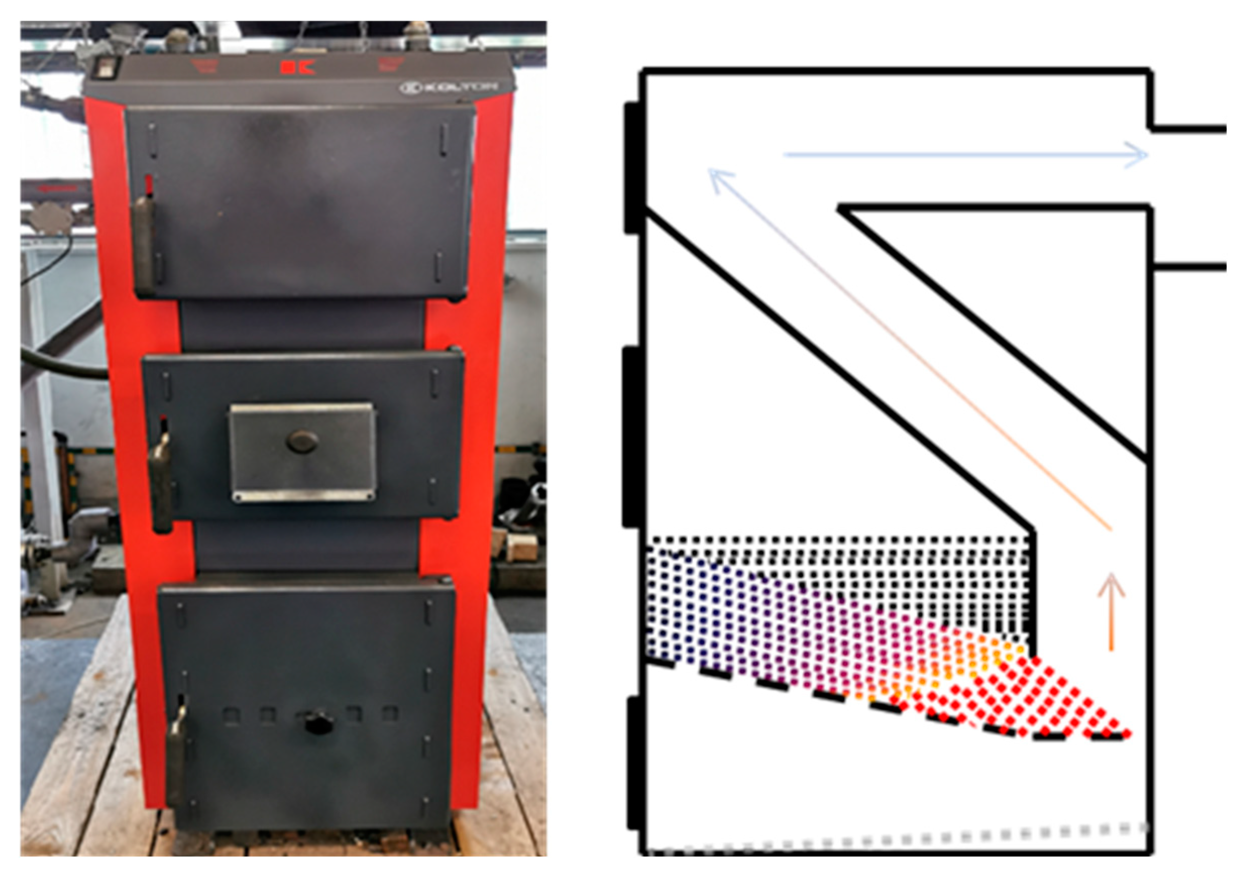
Figure 2.
View and diagram of the boiler no. 2.
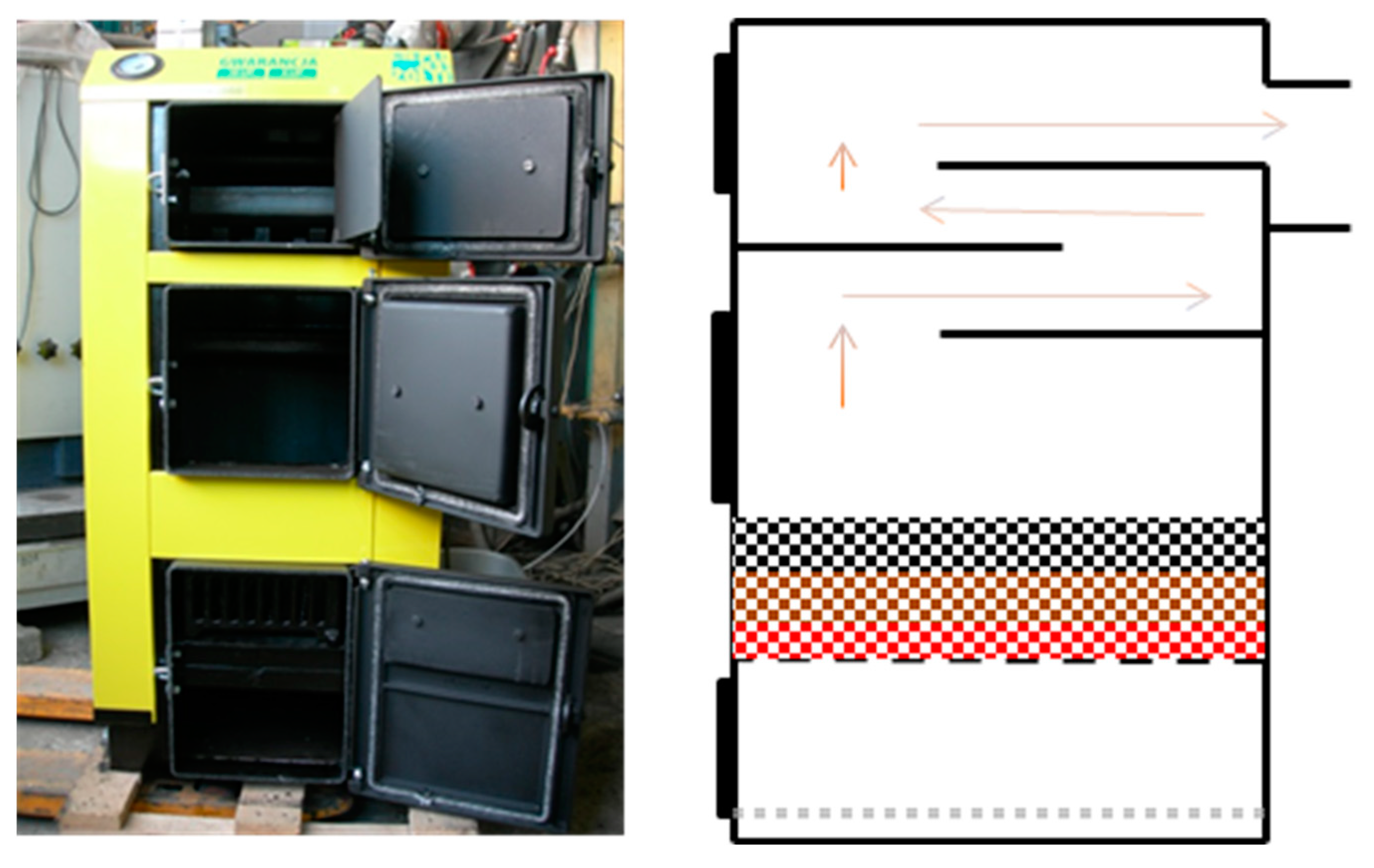
Figure 3.
View of the boiler no. 3.
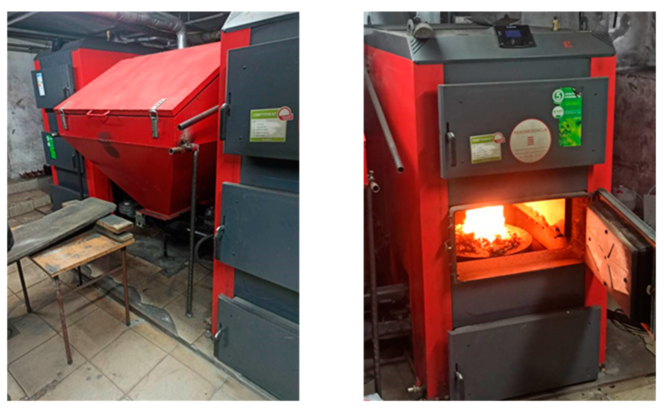
Figure 4.
View of the boiler no. 4.
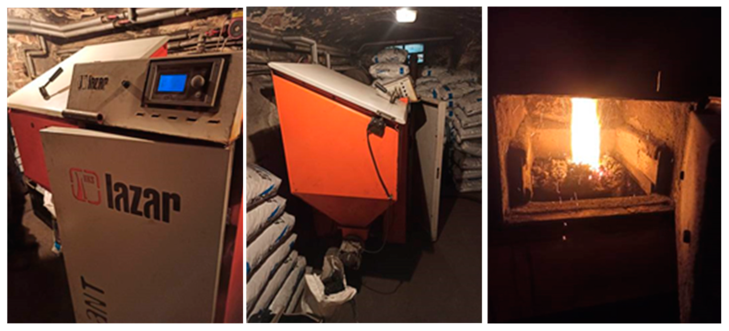
Figure 5.
View of the boiler no. 5.
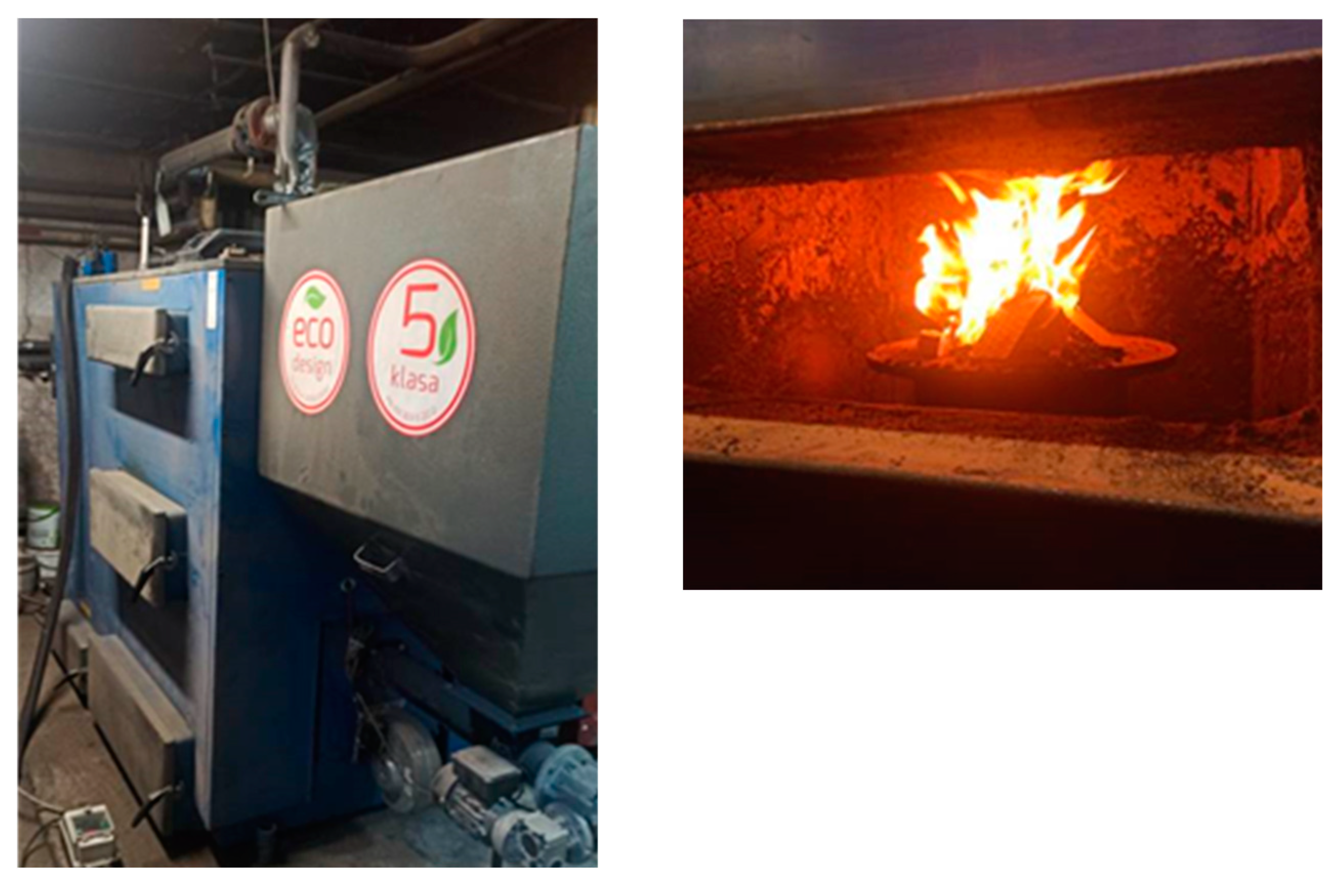
Figure 6.
View of the mobile set of SIEMENS analyzers used for exhaust gas composition testing.
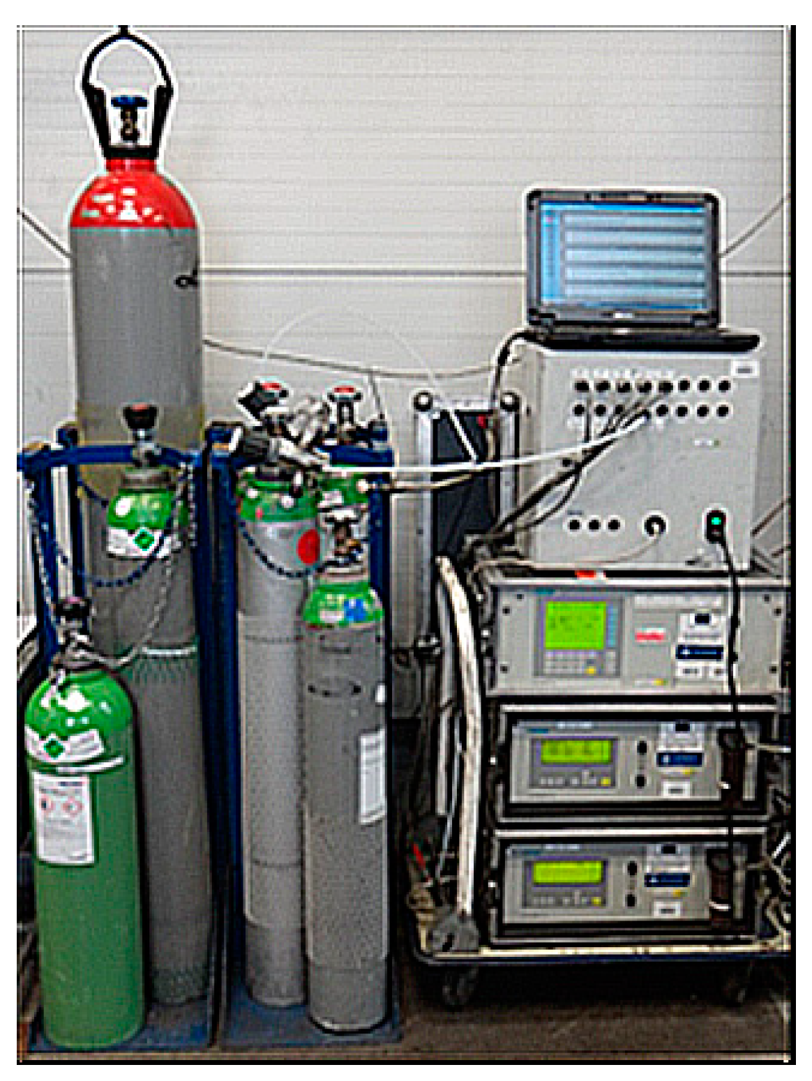
Figure 7.
Mercury emissions depending on its content in the fuel being burned.
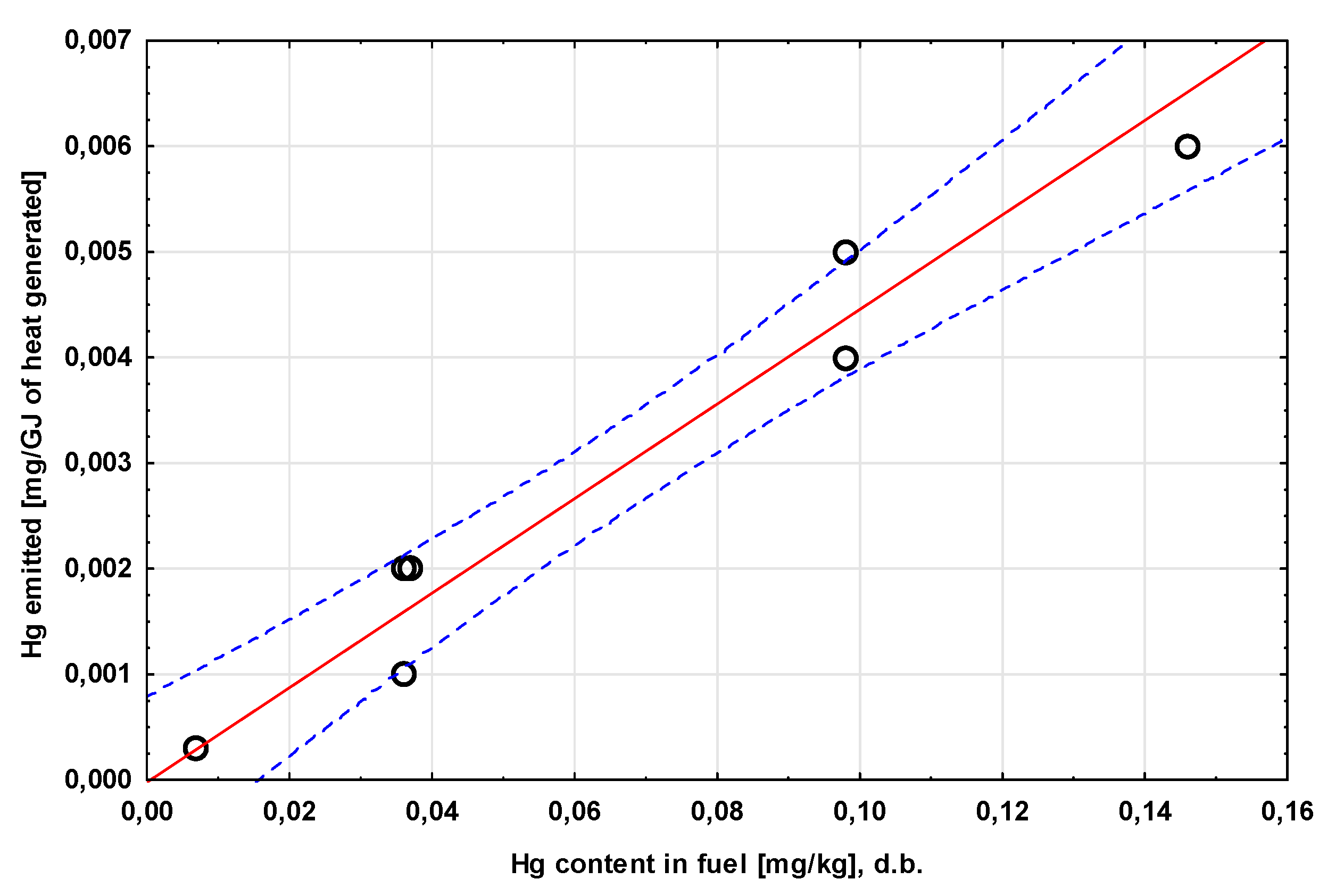

Table 1.
Proximate analysis of the tested fuels (as received basis).
| Parameter | Unit | C1 | C2 | C3 | BC | CBC |
|---|---|---|---|---|---|---|
| moisture content | % | 4.0±0.01 | 6.6±0.02 | 13.1±0.08 | 14.9±0.09 | 7.8±0.02 |
| ash content | % | 6.3±0.01 | 11.1±0.02 | 7.0±0.01 | 6.5±0.01 | 6.2±0.01 |
| volatile matter content | % | 17.6±0.06 | 29.4±0.09 | 32.1±0.10 | 3.1±0.01 | 28.6±0.09 |
| fixed carbon | % | 72.1±0.08 | 52.9±0.13 | 47.8±0.19 | 75.5±0.11 | 57.4±0.12 |
| LCV | J/g | 29497 | 25633 | 24393 | 26065 | 27373 |
Table 2.
Ultimate analysis of the tested fuels (dry basis).
| Parameter | Unit | C1 | C2 | C3 | BC | CBC |
|---|---|---|---|---|---|---|
| carbon content | % | 83.1±0.4 | 72.6±0.4 | 72.7±0.4 | 88.6±0.4 | 77.4±0.4 |
| hydrogen content | % | 3.2±0.01 | 4.0±0.01 | 4.8±0.01 | 1.3±0.00 | 4.3±0.01 |
| sulfur content | % | 0.9±0.00 | 0.3±0.00 | 1.3±0.00 | 0.4±0.00 | 0.8±0.00 |
| nitrogen content | % | 1.1±0.00 | 2.0±0.00 | 1.3±0.00 | 1.6±0.00 | 1.5±0.00 |
| oxygen content | % | 5.2±0.42 | 9.2±0.43 | 11.9±0.42 | 0.4±0.41 | 9.3±0.42 |
| mercury content | mg/kg | 0.146±0.015 | 0.037±0.004 | 0.098±0.010 | 0.007±0.001 | 0.036±0.004 |
Table 3.
Schematic representation of the experiments performed.
| fuel | |||||
| C1 | C2 | C3 | BC | CBC | |
| boiler no. 1 | B1/C1 | ||||
| boiler no. 2 | B2/C2 | B2/BC | |||
| boiler no. 3 | B3/C3 | B3/CBC | |||
| boiler no. 4 | B4/C3 | B4/CBC | |||
| boiler no. 5 | B5/C3 | B5/CBC | |||
Table 4.
Results of the measurements carried out using boilers with manual fuel feeding.
| Parameter | Unit | B1/C1 | B2/C2 | B2/BC |
|---|---|---|---|---|
| energy parameters | ||||
| fuel flow | kg/h | 2.0 | 3.0 | 3.8 |
| lambda | - | 1.95 | 2.21 | 3.30 |
| boiler efficiency | % | 76.0 | 72.2 | 67.6 |
| boiler power | kW | 12.4 | 15.4 | 18.6 |
| relative thermal load of the boiler | % | 103.4 | 102.7 | 124.0 |
| flue gas parameters | ||||
| flue gas temperature | °C | 187.8 | 256.0 | 254.5 |
| chimney draught | Pa | -11.8 | -25.2 | -31.5 |
| O2 concentration | % | 10.33 | 11.57 | 14.57 |
| CO2 concentration | 9.40 | 8.08 | 5.84 | |
| converted to 10% O2 | 9.69 | 9.42 | 10.00 | |
| CO concentration | mg/Nm3 | 436.1 | 4256.1 | 2755.1 |
| converted to 10% O2 | 458.9 | 4967.4 | 4712.1 | |
| SO2 concentration | 967.8 | 259.8 | 178.5 | |
| converted to 10% O2 | 996.7 | 303.0 | 305.3 | |
| NO concentration | 161.6 | 143.6 | 47.9 | |
| converted to 10% O2 | 255.1 | 256.6 | 112.8 | |
| dust concentration | 22.3 | 144.4 | 31.1 | |
| converted to 10% O2 | 23.0 | 166.9 | 53.2 | |
| TOC concentration | 31.5 | 101.2 | 45.9 | |
| converted to 10% O2 | 32.5 | 116.7 | 78.6 | |
| emissions | ||||
| CO2 | kg/GJ | 95.8 | 91.2 | 93.4 |
| CO | g/GJ | 231.1 | 2433.2 | 2229.4 |
| SO2 | g/GJ | 498.2 | 148.4 | 144.4 |
| NO | g/GJ | 127.4 | 125.7 | 59.4 |
| dust | g/GJ | 11.5 | 81.8 | 25.2 |
| TOC | g/GJ | 16.3 | 57.1 | 37.2 |
Table 5.
Results of the measurements carried out using boilers with automatic fuel feed.
| Parameter | Unit | B3/C3 | B3/CBC | B4/C3 | B4/CBC | B5/C3 | B5/CBC |
|---|---|---|---|---|---|---|---|
| energy parameters | |||||||
| fuel flow | kg/h | 6.5 | 6.3 | 0.9 | 0.8 | 12.2 | 11.7 |
| lambda | - | 2.4 | 2.3 | 3.8 | 2.8 | 4.1 | 3.9 |
| boiler efficiency | % | 88.5 | 87.5 | 71.4 | 79.5 | 70.6 | 74.3 |
| boiler power | kW | 39.0 | 41.9 | 4.4 | 4.8 | 58.4 | 66.1 |
| relative thermal load of the boiler | % | 39.0 | 41.9 | 18.3 | 20.0 | 38.9 | 44.1 |
| flue gas parameters | |||||||
| flue gas temperature | °C | 117.6 | 118.6 | 202.3 | 207.0 | 172.3 | 181.6 |
| chimney draught | Pa | 30.3 | 30.7 | 22.0 | 25.0 | 20.7 | 28.9 |
| O2 concentration | % | 12.52 | 11.81 | 15.60 | 13.48 | 16.00 | 15.73 |
| CO2 concentration | 7.13 | 7.86 | 4.48 | 6.43 | 4.18 | 4.45 | |
| converted to 10% O2 | 9.25 | 9.41 | 9.13 | 9.41 | 9.20 | 9.29 | |
| CO concentration | mg/Nm3 | 654.6 | 607.9 | 1507.1 | 660.9 | 475.9 | 462.0 |
| converted to 10% O2 | 849.1 | 727.8 | 3069.4 | 967.2 | 1047.9 | 964.9 | |
| SO2 concentration | 1207.7 | 786.3 | 570.0 | 542.8 | 611.3 | 396.5 | |
| converted to 10% O2 | 1566.6 | 941.3 | 1160.8 | 794.4 | 1346.1 | 828.1 | |
| NO concentration | 345.2 | 342.0 | 294.9 | 259.4 | 187.8 | 197.4 | |
| converted to 10% O2 | 447.8 | 409.3 | 600.7 | 379.5 | 413.0 | 412.1 | |
| dust concentration | 128.3-133.8 | 82.7-100.3 | 138.5-151.3 | 89.5-105.1 | 67.6-70.3 | 55.1-62.0 | |
| converted to 10% O2 | 166.4-173.6 | 99.0-120.1 | 282.1-308.2 | 131.0-153.8 | 148.9-154.8 | 115.1-129.5 | |
| emissions | |||||||
| CO2 | kg/GJ | 89.4 | 90.4 | 88.2 | 90.3 | 88.9 | 89.2 |
| CO | g/GJ | 415.1 | 353.5 | 1500.7 | 469.7 | 511.8 | 468.5 |
| SO2 | g/GJ | 765.8 | 457.3 | 567.5 | 385.8 | 657.4 | 402.1 |
| NO | g/GJ | 218.9 | 198.9 | 293.6 | 184.4 | 201.9 | 200.2 |
| dust | g/GJ | 81.4-84.8 | 48.1-58.3 | 137.9-150.7 | 63.6-74.7 | 72.7-75.6 | 55.9-62.9 |
Table 6.
Results of the calculations based on the mercury analyses performed for the fuels tested and the bottom ashes produced during the combustion tests.
Table 6.
Results of the calculations based on the mercury analyses performed for the fuels tested and the bottom ashes produced during the combustion tests.
| Parameter | Unit | B1/C1 | B2/C2 | B2/BC | B3/C3 | B3/CBC | B4/C3 | B4/CBC | B5/C3 | B5/CBC |
|---|---|---|---|---|---|---|---|---|---|---|
| Hg flux delivered with fuel | mg/kg | 0.140 | 0.035 | 0.006 | 0.085 | 0.033 | 0.085 | 0.033 | 0.085 | 0.033 |
| ng/GJ | 4.75 | 1.37 | 0.23 | 3.48 | 1.21 | 3.48 | 1.21 | 3.48 | 1.21 | |
| amount of Hg delivered with fuel | % | 100 | ||||||||
| amount of Hg remaining in bottom ash | % | 5.76 | 1.92 | 2.75 | 1.83 | 2.90 | 0.78 | 3.05 | 1.99 | 3.74 |
| amount of Hg emitted into the atmosphere | % | 94.24 | 98.08 | 97.25 | 98.17 | 97.10 | 99.22 | 96.95 | 98.01 | 96.26 |
| the amount of Hg emitted with flue gas (including dust) per GJ of useful heat generated | mg/GJ | 6×10⁻³ | 2×10⁻³ | 3×10⁻⁴ | 4×10⁻³ | 1×10⁻³ | 5×10⁻³ | 1×10⁻³ | 5×10⁻³ | 2×10⁻³ |
Disclaimer/Publisher’s Note: The statements, opinions and data contained in all publications are solely those of the individual author(s) and contributor(s) and not of MDPI and/or the editor(s). MDPI and/or the editor(s) disclaim responsibility for any injury to people or property resulting from any ideas, methods, instructions or products referred to in the content. |
© 2023 by the authors. Licensee MDPI, Basel, Switzerland. This article is an open access article distributed under the terms and conditions of the Creative Commons Attribution (CC BY) license (http://creativecommons.org/licenses/by/4.0/).
Copyright: This open access article is published under a Creative Commons CC BY 4.0 license, which permit the free download, distribution, and reuse, provided that the author and preprint are cited in any reuse.


