
Submitted:
15 June 2023
Posted:
15 June 2023
You are already at the latest version
Abstract
Most of the fishing currently practiced in Japan is done by small vessels with a small number of fishermen (one or two). One of the most common fishing methods is longline fishing. However, this method requires the vessel to operate at a constant low speed because the depth of the hook must be kept constant while adjusting the speed of the fishing boat to the tidal current. In addition, because the vessel must maneuver and fish at the same time, automation is desired. Thus, we propose a robotic system that can control the depth of the trap at a constant depth even when the speed of the vessel and the current change, and that can successfully fish without the need for skilled fishermen. Fishing can be conducted regardless of the speed of the vessel, whereas currently it is controlled by the speed of the vessel and the tidal current. Therefore, it may contribute to proposing new fishing methods as well as the existing ones. This can contribute to the shortage of successors to the fishing industry and to the revitalization of the fishing industry.
Keywords:
Automatically controlled robot
; Longline fishing
; Low speed
1. Introduction
1.1. Current Status of Coastal Fisheries and Longline Fishery
Japan covers an area of only 3.8 million square kilometers (61st in the world), and its territorial waters and exclusive economic zones reach 4.47 million square kilometers (6th in the world) [1,2]. According to the Fisheries Agency [3], more than 90% of the fishery operators in Japan in the marine fisheries and aquaculture industries are private operators. The problem is that a high percentage of the individual fishery operators have no successors when they become old, making it difficult for them to continue their operations and leading to the closure of their businesses. Group operators, which used to be the mainstay of operations in the 200 nautical mile economic zone [4] and on the high seas, have seen their fishing population continue to decline due to the tightening of the exclusion from the 200 nautical mile zone and other factors. In addition, in areas where there are many small-scale fisheries, many of them are small-scale fisheries operated by one or two people using small boats, and the problem of labor shortages, such as labor saving through smart fishery [5], has become an issue [6].
Shiraishi et al [7] conducted research on an environmentally friendly vessel speed control method to solve these problems. An optimal speed control method using an automated longline fishing method was developed and modeled. They also developed a mechanism to allow vessels to operate at a constant low speed. it is foreseen that labor saving in these fisheries will be increasingly developed through the use of AI [8,9] and IoT [10].
1.2. Conventional longline fishery
Conventional longline fishery is a fishing method in which multiple traps attached to a single rope are pulled by a boat. It consists of one trunk rope with many branch ropes (called longlines) attached to it, with hooks attached to the ends of the branch ropes. Longline fishing is a traditional fishing method in which the longline is set in the fishing grounds, left there for a while, and then retrieved again to reap the catch. Compared to fishing with nets, longlining is time-consuming, labor-intensive, and less efficient. In Japan, simple lures (like rubber ribbons) are generally used as bait, and fish are located with a fish finder and the traps are dropped near the depth where they live. At this point, it is necessary to operate at a slow speed[5] while taking into account the effects of currents. Experience and intuition[11] determine the success of the fishery, and although it is a simple device, it is not a method that everyone can use. It is also not easy to concentrate on either of the two tasks, as one person is often required to operate the boat at a very slow speed and to set the hook, which is similar to single-line fishing and generally traded at a higher price because it does not damage the fish as much as nets. Figure 1 shows a schematic diagram of the longline fishery.
1.3. Development of automated fishing robots
The problem exists that it requires skillful techniques to grasp the depth of the fish and control the position of the traps at low speeds. Therefore, in addition to the low-speed control method, this paper describes the development of a system that automatically controls the depth of the "trap" independent of changes in the current. By using this robot, not only vessels but also fishing can be automated. This will save labor and provide a technology that will support many fishermen. Since the robot is intended for small-scale fishing, it is important that the structure be simple and low-cost[12] in addition to the safety of the functions. Since maintenances [13] are not expected, we were concerned with making the structure simple and less prone to failures.
2. Methods
2.1. Proposal of manball
This paper presents an overview of the operation of the automatic longline system devised in this paper. The name "manball" is derived from its ball-like shape, which somewhat resembles a sunfish. The manball is equipped with a depth sensor to measure its own depth. To maintain a constant depth, the manball is designed to control its own depth by varying buoyancy and lift. The manball controls its depth by adjusting buoyancy and lift. Here, air is injected into the float as a buoyancy regulator. Airplanelike wings are used as lift regulators. Figure 2 shows the Manball (automatic fly-roping system).
2.2. Buoyancy Adjustment Device
An internal structural diagram is shown in Figure 3. The depth sensor for measurement is assumed to be an inexpensive sensor such as those attached to a diver's watch. A barrel body, not a hollow sphere, is installed inside the outer structure to utilize the water surface piston. The barrel body is always oriented toward gravity with a lower weight and hinge. Since the barrel body uses the piston action of the water surface, air pressure must always be applied to the water surface. Therefore, it is necessary to maintain a constant posture, but to keep the cost low, expensive devices such as a gyro are not used, and a weight is attached so that the barrel body always faces the direction of gravity at the hinge. The key design points are to connect air tubes to each manball with accompanying wires, and to allow enough length for the barrel body to move inside.
2.3. Overall Control System
As for the overall system configuration, first, target values for vessel speed and depth are set when the fish finder responds. Next, the average value of the signal acquired from the depth sensor attached to the main unit is fed back, compared with the respective target values for vessel speed and depth, and signals are sent from the controller to the motors of the buoyancy regulator and circular wing system. The air compressor and controller are mounted on board. In this case, wires and tubes for transmitting electrical signals must accompany the system. If the vehicle is only to be raised or lowered, no wires are used because a circular wing system for rapid descent and ascent is not required. Depth sensors can be attached to the tubes by wires or send signals wirelessly. When the air pressure inside the tube is set to atmospheric pressure or to negative pressure by attaching a valve, seawater automatically enters through the hole and floods the tube. The overall control system is shown in Figure 4.
3. Simulation Results
3.1. Buoyancy Control Device
In this study, the simple operation of the buoyancy regulator was confirmed by simulation. Air was supplied from the upper tube and pressure was applied to the water surface. The air pressure acting on the water surface area acts as a force that causes the water to be ejected. This is the water surface piston action. Initially, the water surface area is too small to generate an effective force. When the water surface passes the center, the area of the water surface becomes smaller again. Therefore, a barrel shape was considered appropriate. Since this method requires attitude control so that air pressure is always applied to the water surface, it was necessary to add weights to adjust the buoyancy. Figure 5 shows an overview of the buoyancy regulator operation.
3.2. Tubing
Each manball is operated by air supplied from the ship, so several manballs are connected by air hoses. The inside of the manball is set so that it always faces the direction of gravity, but it is possible that the main body may rotate. Therefore, the tubes used in the device were designed to rotate freely along the rails by using a joint component near the air inlet, taking into consideration the case where the main body rotates in the sea. An overview of the tubes is shown in Figure 6.
3.3. Lift Adjustment Device
Although it is possible to adjust the depth by buoyancy alone, to reach the target depth more quickly, we used wings as a device to raise the device along with buoyancy. Wings like those of ordinary airplanes and hydrofoils cannot raise the robot when it rotates. Therefore, a circular wing was considered optimal because it could provide thrust even when the robot rotated slightly. The circular wings are adjusted so that the angle of the wings can be changed by a motor. Although the motor is used to move the wing, a rust-resistant air cylinder could be used as a power source using only air pressure. Figure 7 shows the lift regulator.
4. Discussion
In the future, we envision the development of unmanned vessels that can be operated in conjunction with the system devised in this paper and a fish finder, etc. If GPS, etc., is used, automatic operation in restricted waters, etc., will be possible. In addition, linking this system with fishfinders is within the scope of modern technology and feasibility, so it is considered feasible within the limits of the law.
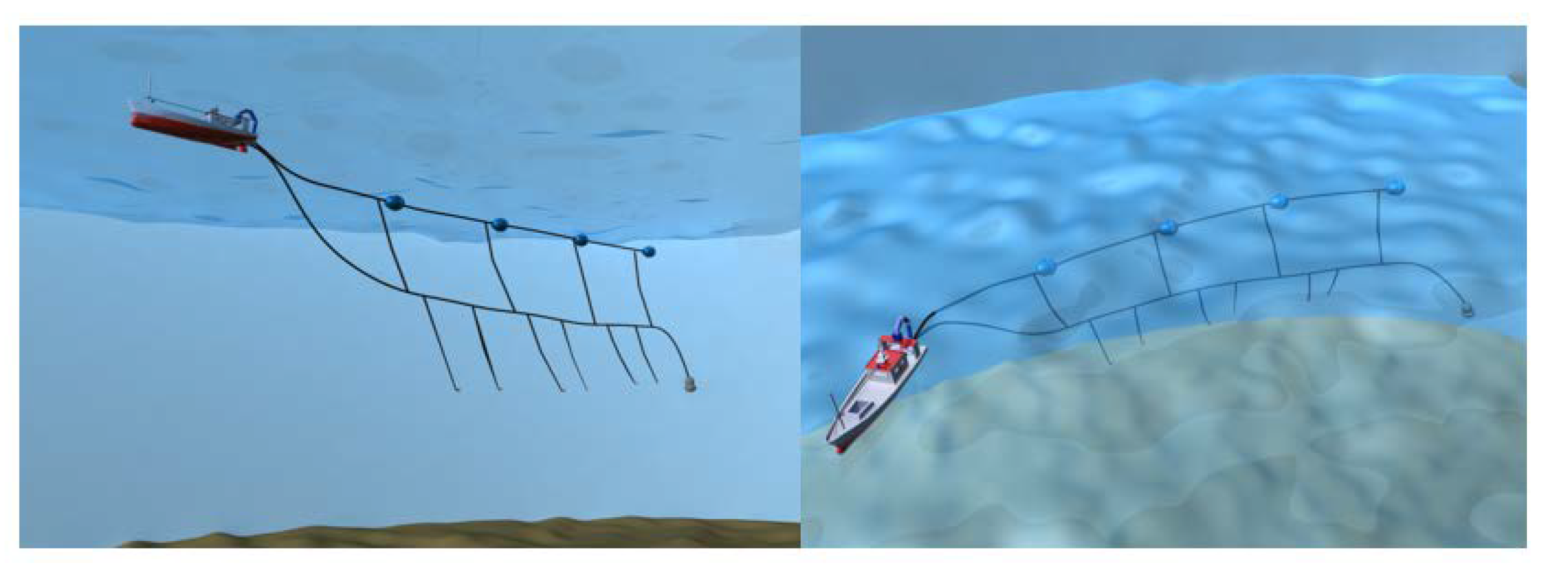
If small vessels capable of unmanned operation at low speeds are developed, it would be possible to run the vessels unmanned after sunset and retrieve the fish after sunrise. This system could make a significant contribution to the shortage of human resources in the fishing industry. Figure 8 shows future vision of fully automated longline fishing. This paper simply deploys a manball in a conventional longline fishery and does not require a complicated deployment structure. Recovery of the manballs is also easy, since all that is required is to pull a wire with a tube attached. This paper only presents a concept, and demonstration tests will be the subject of future studies.
4. Conclusions
We surveyed fisheries in Japan to understand the specifications required for longline fishing. In addition to a buoyancy regulator, a lift regulator was added. A simple and inexpensive system was devised to achieve these structures. The system uses the surface of the water as a piston and circular wings as a mechanism to raise and lower the trap. First, when the fish finder responds, target values for vessel speed and depth are set. Next, the average value of the signal acquired from the depth sensor attached to the main unit is fed back, compared with the respective target values for vessel speed and depth, and signals are sent from the controller to the buoyancy regulator and the motor of the circular wing system. Linking this system to a fish finder is within the feasible range of modern technology and is considered feasible well within the limits of the law. The authors hope that this system will greatly improve labor savings for future fishermen.
Author Contributions
H.S. (Harhiro Shiraishi) and H.S. (Hajime Shiraishi) participated in the study design and analysis of the manuscript.
Funding
This research received no external funding.
Data Availability Statement
Not applicable.
Conflicts of Interest
The authors declare no conflict of interest. The funders had no role in the design of the study; in the collection, analyses, or interpretation of data; in the writing of the manuscript; or in the decision to publish the results.
References
- Ikegawa, Y.; Tobase, T. Estimation of potential oceanic regions and possible CO2 amounts for storage using self-sealing of CO2 hydrate around Japan. J. JSCE 2021, 9, 276–283. [Google Scholar] [CrossRef] [PubMed]
- Yang, B.; Liu, Y. Japan’s marine economic development and competition with China. Ccamlr. Sci. 2018, 25, 83–96. [Google Scholar]
- Fisheries Agency, Japanese Government. https://www.jfa.maff.go.jp/e/.
- Hollick, A. (1977). The Origins of 200-Mile Offshore Zones. American Journal of International Law, 71, 3, 494–500. [CrossRef]
- Honarmand Ebrahimi, S.; Ossewaarde, M.; Need, A. Smart Fishery: A Systematic Review and Research Agenda for Sustainable Fisheries in the Age of AI. Sustainability 2021, 13, 6037. [Google Scholar] [CrossRef]
- Yao, W.; Zhang, W.; Li, W.; Li, P. Measurement and Evaluation of Convergence of Japan’s Marine Fisheries and Marine Tourism. Sustainability 2022, 14, 9108. [Google Scholar] [CrossRef]
- Shiraishi, H.; Shiraishi, H. Development of a Speed Control Device for Fishing Vessels at Low Speeds and Simulation of the Control System. Automation 2022, 3, 545–562. [Google Scholar] [CrossRef]
- Yang, X.; Zhang, S.; Liu, J.; Gao, Q.; Dong, S.; Zhou, C. Deep learning for smart fish farming: Applications, opportunities and challenges. Rev. Aquac. 2020, 13, 66–90. [Google Scholar] [CrossRef]
- Fosso, K.; Wamba, S.; Bawack, R.; Guthrie, C.; Queiroz, M.; Carillo, K. Are we preparing for a good AI society? A bibliometric review and research agenda. SSRN Electron. J. 2021, 164, 120482. [Google Scholar] [CrossRef]
- Siskandar, Ridwan, et al. "Control and Automation: Insmoaf (Integrated Smart Modern Agriculture and Fisheries) on The Greenhouse Model." Jurnal Ilmu Pertanian Indonesia 27.1 (2022): 141-152. [CrossRef]
- Nordmo, Tor-Arne Schmidt, et al. "Fish AI: Sustainable Commercial Fishing Challenge." (2022).
- Jones, Andrew W., et al. "Learning from the study fleet: Maintenance of a large-scale reference fleet for northeast US fisheries." Frontiers in Marine Science (2022): 641. [CrossRef]
Figure 1.
Schematic diagram of longline fishing.
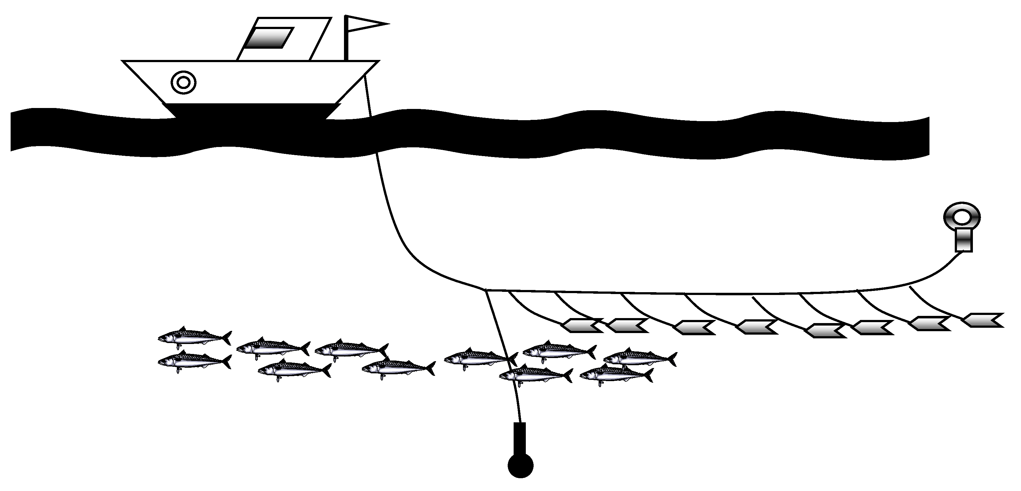
Figure 2.
Manball (automatic fly-roping system).
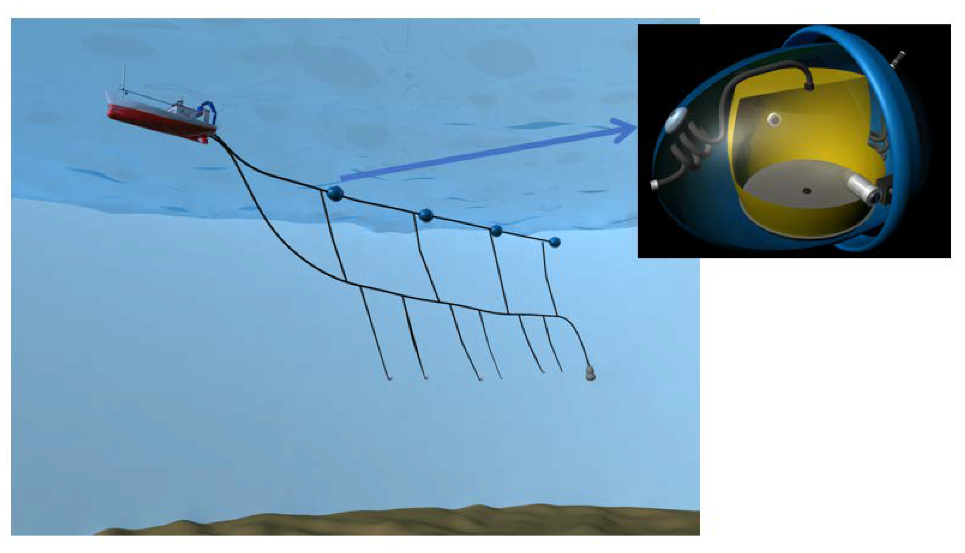
Figure 3.
Buoyancy adjustment device.
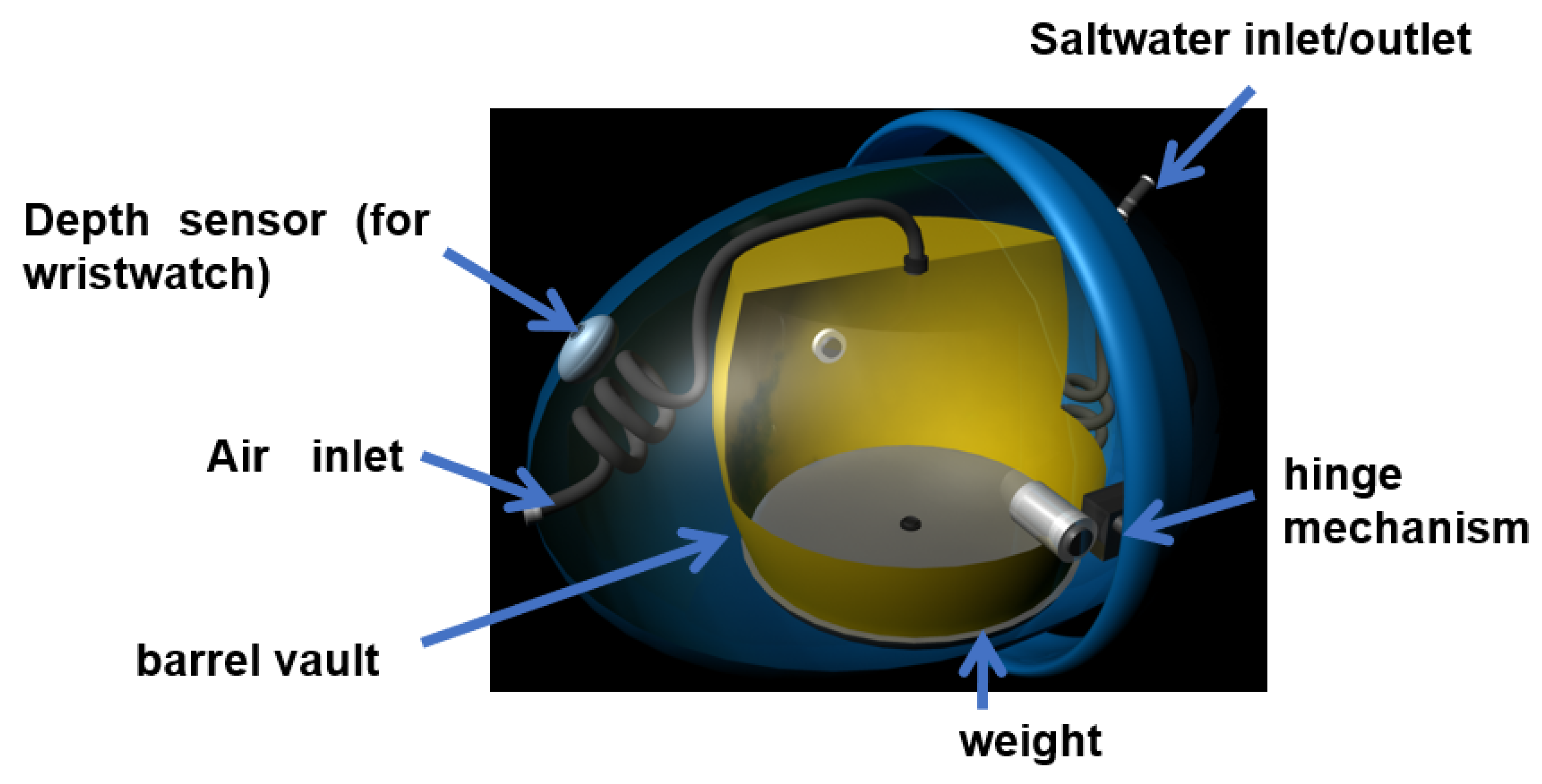
Figure 4.
Overall control system.
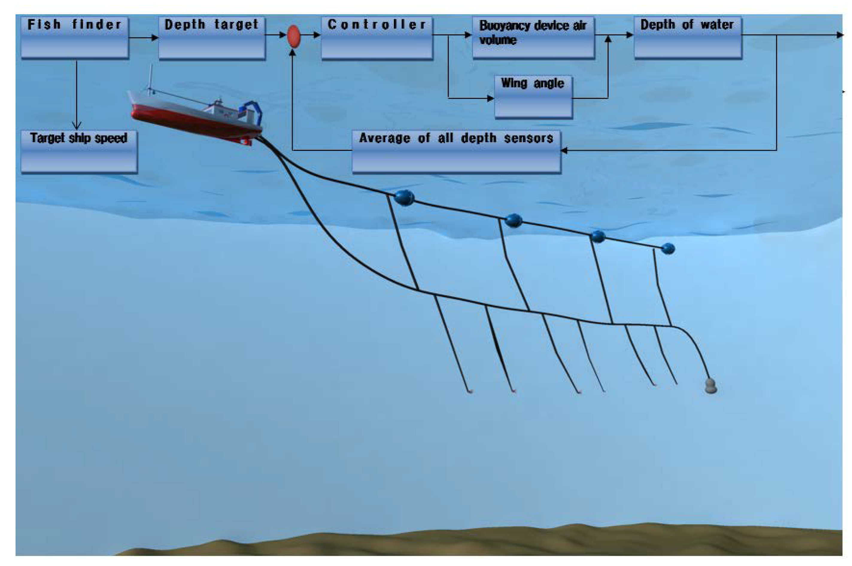
Figure 5.
Overview of buoyancy regulator operation.
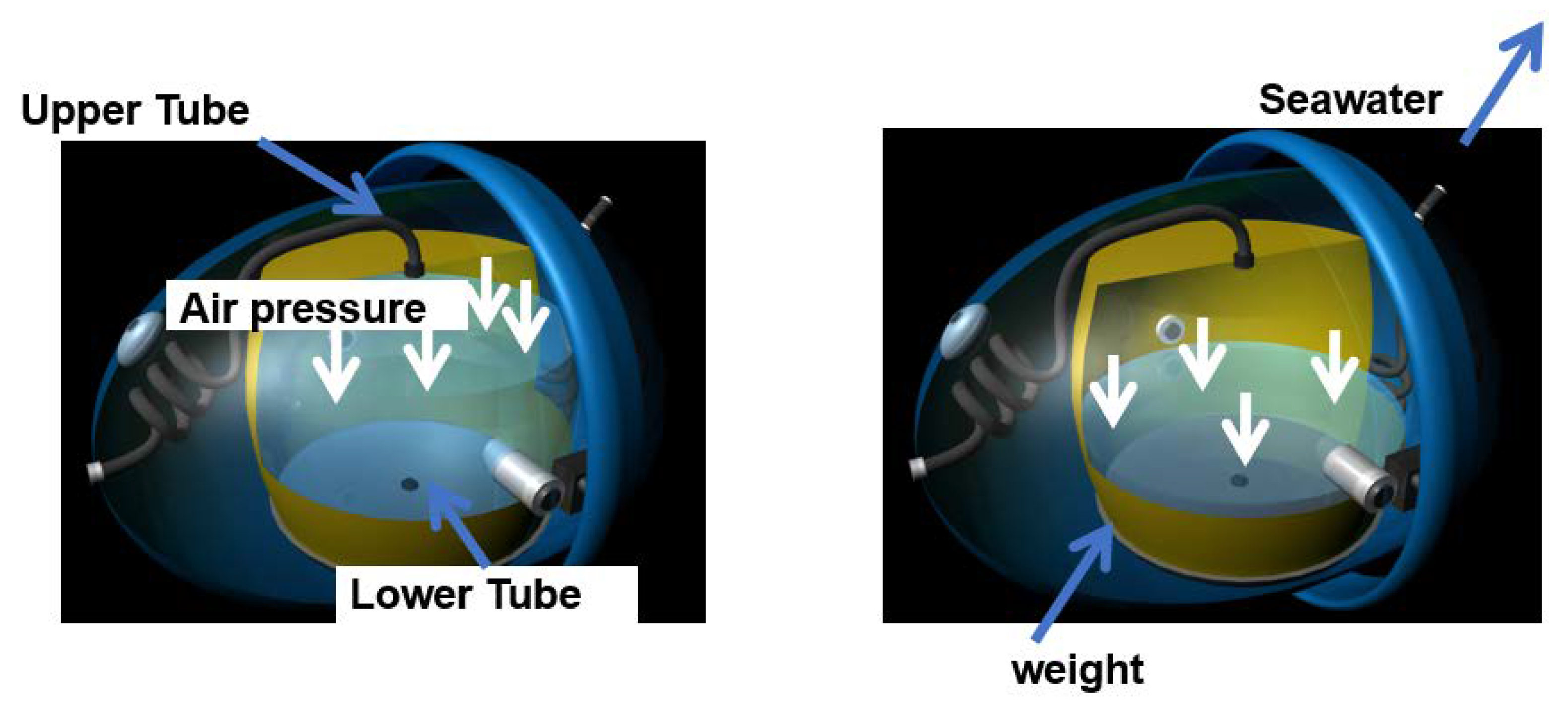
Figure 6.
An overview of the tubes.
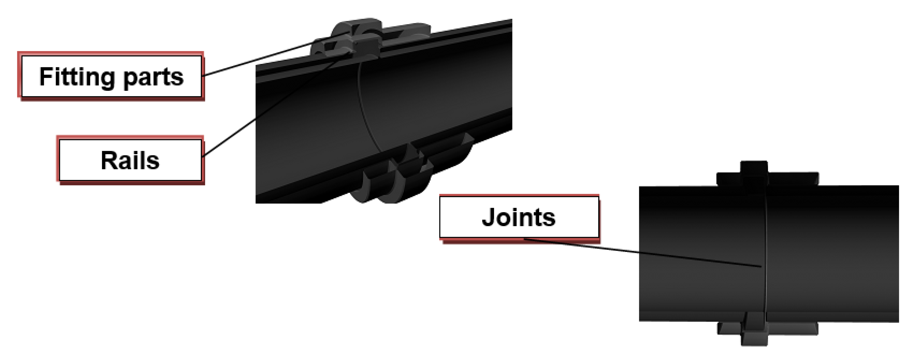
Figure 7.
Lift Adjustment Device.
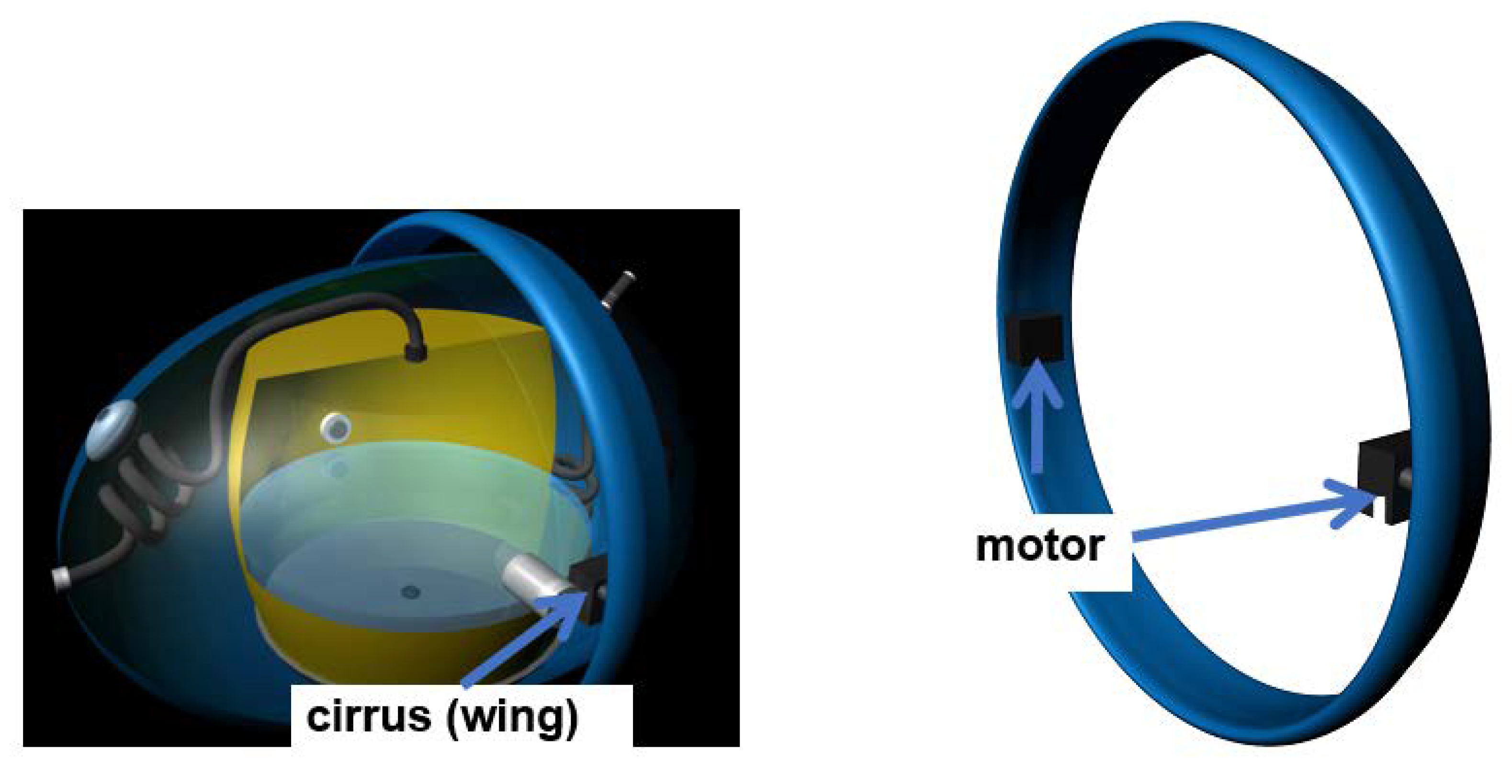
Figure 8.
Future vision of fully automated longline fishing.
Disclaimer/Publisher’s Note: The statements, opinions and data contained in all publications are solely those of the individual author(s) and contributor(s) and not of MDPI and/or the editor(s). MDPI and/or the editor(s) disclaim responsibility for any injury to people or property resulting from any ideas, methods, instructions or products referred to in the content. |
© 2023 by the authors. Licensee MDPI, Basel, Switzerland. This article is an open access article distributed under the terms and conditions of the Creative Commons Attribution (CC BY) license (http://creativecommons.org/licenses/by/4.0/).
Copyright: This open access article is published under a Creative Commons CC BY 4.0 license, which permit the free download, distribution, and reuse, provided that the author and preprint are cited in any reuse.


