Submitted:
14 February 2025
Posted:
14 February 2025
You are already at the latest version
Abstract
This study aims to enhance the maneuverability and monitoring capabilities of biomimetic robotic fish in aquatic environments. A three joint biomimetic fish with forked tail fins was designed based on the body and tail fin (BCF) model to optimize propulsion efficiency and mimic natural fish swimming. The mechanical structure uses servo modules connected in series to simulate spinal joints, and precise control is achieved through PWM signals and Arduino based systems. The tail fin design follows the principles of fluid dynamics, especially the anti Karman vortex street effect, while the ballast mechanism is used to adjust the pitch angle to achieve vertical motion. The robotic fish integrates temperature, pH, and turbidity sensors for real-time water quality monitoring and data transmission through WiFi. The experimental results show that the swimming speed of the bionic fish is 0.018 m/s, the turning angular velocity is 15 °/s, and the maximum pitch angle is 5.69 °, verifying its good maneuverability. The water quality monitoring experiment shows that compared with traditional methods, the deviations of water temperature, pH value, and turbidity are 0.67%, 0.05%, and 0.23%, respectively, which meet the accuracy requirements of water quality parameter detection. This design successfully combines biomimetic motion with embedded sensing technology, providing a compact solution for dynamic aquatic monitoring. Although the system has shown potential in environmental applications, improvements in speed, maneuverability, and sensor accuracy are still needed in the future to enhance its operational capabilities in complex underwater environments.
Keywords:
bionics
; Embedded Design
; Biomimetic mechanical fish
; Water quality sensors
1. Introduction
The evolution of nature has shaped living organisms in extraordinary ways, optimizing their functionality and resilience [1,2]. This is especially evident in the underwater environments of rivers, seas, and oceans. With advancements in technology and intellectual capabilities, humanity is striving to replicate the swimming abilities of fish through bionic robot designs [3]. Underwater robots are already being employed in various fields, such as environmental monitoring, marine resource exploration, and scientific research. However, the aquatic environment presents numerous challenges for the operation of such robots [4]. The complexity and unpredictability of underwater conditions limit the effectiveness of robotic systems, significantly reducing their adaptability and functionality [5].
Numerous researchers and scientists across the globe have made substantial progress in the field of mechanical bionic fish [6]. However, there remains a considerable gap between the capabilities of bionic robotic fish and those of their biological counterparts. Fish are capable of traveling long distances, achieving high cruising speeds, and demonstrating exceptional maneuverability. The key to these abilities lies in their mode of movement, which has become the central focus of research into the design and control systems of bionic robots. The specific design of these robots depends heavily on their intended applications, such as oceanography, underwater research, archaeology, search and rescue missions, patrolling, and environmental monitoring [7].
Current research on bionic robotic fish covers a broad range of topics, from the study of fish morphology and sensory systems to kinematic and hydrodynamic analysis, mechanical design, control methodologies, and field testing [8]. The development of self-propelled robotic fish began in the early 1990s with projects like RoboTuna and RoboPike, pioneered by the Massachusetts Institute of Technology and the Draper Laboratory [9]. Since then, extensive research and design have been conducted worldwide, yielding both scientific and practical advancements [10]. Modern technologies such as computer simulation, 3D printing, and miniaturization of components offer significant opportunities for further progress [11]. Examples include 3D swimming robotic fish, boxfish-inspired robots, and soft robotic fish, all of which have proven effective in specific tasks such as monitoring aquatic environments [12].
Despite the progress, bionic fish robots still have significant room for improvement. These robots, designed with simple Central Pattern Generator (CPG) controllers, are generally capable of mimicking the swimming behavior of real fish, allowing for greater maneuverability and stability in the water [13]. Bionic fish robots are more flexible, efficient, and environmentally friendly compared to traditional robotic systems, making them ideal candidates for water quality monitoring in various aquatic environments. By combining bionic fish with advanced sensing technologies, more autonomous and intelligent monitoring systems can be created, overcoming the limitations of conventional inland water monitoring technologies [14]. Some researchers have equipped robotic fish with sensors for large-scale water quality monitoring; however, the size and design limitations of these robots prevent them from operating effectively in complex environments [15].
Despite the advancements, a significant challenge remains: the lack of reliable and effective bionic fish robots for water quality monitoring that are both unobtrusive and capable of performing in diverse and complex environments [16]. While there has been progress in the design and development of bionic robotic fish, there is still a lack of sufficient practical applications, particularly in real-time dynamic monitoring of aquatic environments [17]. However, as intelligent sensing technology for aquatic environments continues to develop, the integration and functionality of bionic fish robots are expected to improve significantly, offering new solutions for measuring water quality [18].
Our contributions can be summarized as follows:
- (1)
- A novel biomimetic robotic fish design is proposed, which incorporates the Body and Caudal Fin (BCF) model to optimize the maneuverability and propulsion efficiency in aquatic environments.
- (2)
- A driven three-joint mechanism and a tail fin propulsion optimization module are designed, aiming to replicate natural fish movement and increase maneuverability in dynamic water environments. Additionally, a real-time water quality monitoring system is integrated to provide continuous environmental data collection with enhanced flexibility.
- (3)
- Extensive experiments were conducted on various aquatic environments, showing that our proposed approach outperforms traditional methods in terms of maneuverability, propulsion efficiency, and real-time water quality monitoring.
The goal of this article is to present the development of a new design and control system aimed at enhancing the movement and maneuvering capabilities of bionic fish robots, as well as improving the monitoring process for inland water bodies [19]. This article is structured as follows: Section 2 presents studies on the robot’s design, Section 3 describes the development of the control system, Section 4 covers experimental studies of the robot’s kinematics, Section 5 presents the results of testing the bionic fish robot, and Section 6 concludes with a discussion of research prospects and conclusions.
2. Materials and Methods
2.1. Bionic Mechanical Fish Drive Design
Fish rely on various fins for swimming, and each fin plays a specific role. The pectoral fins, for example, use the resistance of water to assist with turning. When a fish swims and only one side of its pectoral fins is deployed, the fish turns toward the side with the deployed fin due to the resistance. If both sides are deployed simultaneously, this creates a braking effect. While the fish is stationary, its pectoral fins move back and forth, allowing the fish to slowly move forward. In some fish species, the pectoral fins can even be used to propel the fish backward [20]. The dorsal fin, located along the top of the fish’s body, is crucial for maintaining stability. Additionally, it helps the fish sense the direction and strength of the water flow [21]. To reduce resistance during high-speed swimming, fish retract their dorsal fins closely to their bodies.
The caudal fin, or tail fin, is the primary source of propulsion for most fish. When the tail swings to one side, it propels the fish forward, and the body follows by turning in the same direction. The caudal fin plays a vital role in both providing power and controlling the direction of movement. Therefore, it is considered the most important fin for efficient swimming [22]. The shape of the tail fin varies among different fish species. For example, tuna have crescent-shaped tails, while species like eels, peacock fish, and map fish have more circular tail fins. Cod and six-line fish possess slightly concave tails, while species like crucian carp have a slightly forked tail. The fork-shaped tail is common in fish like fighting fish and seven-star bottom lantern fish.
Figure 1.
Types of tail fin shapes.
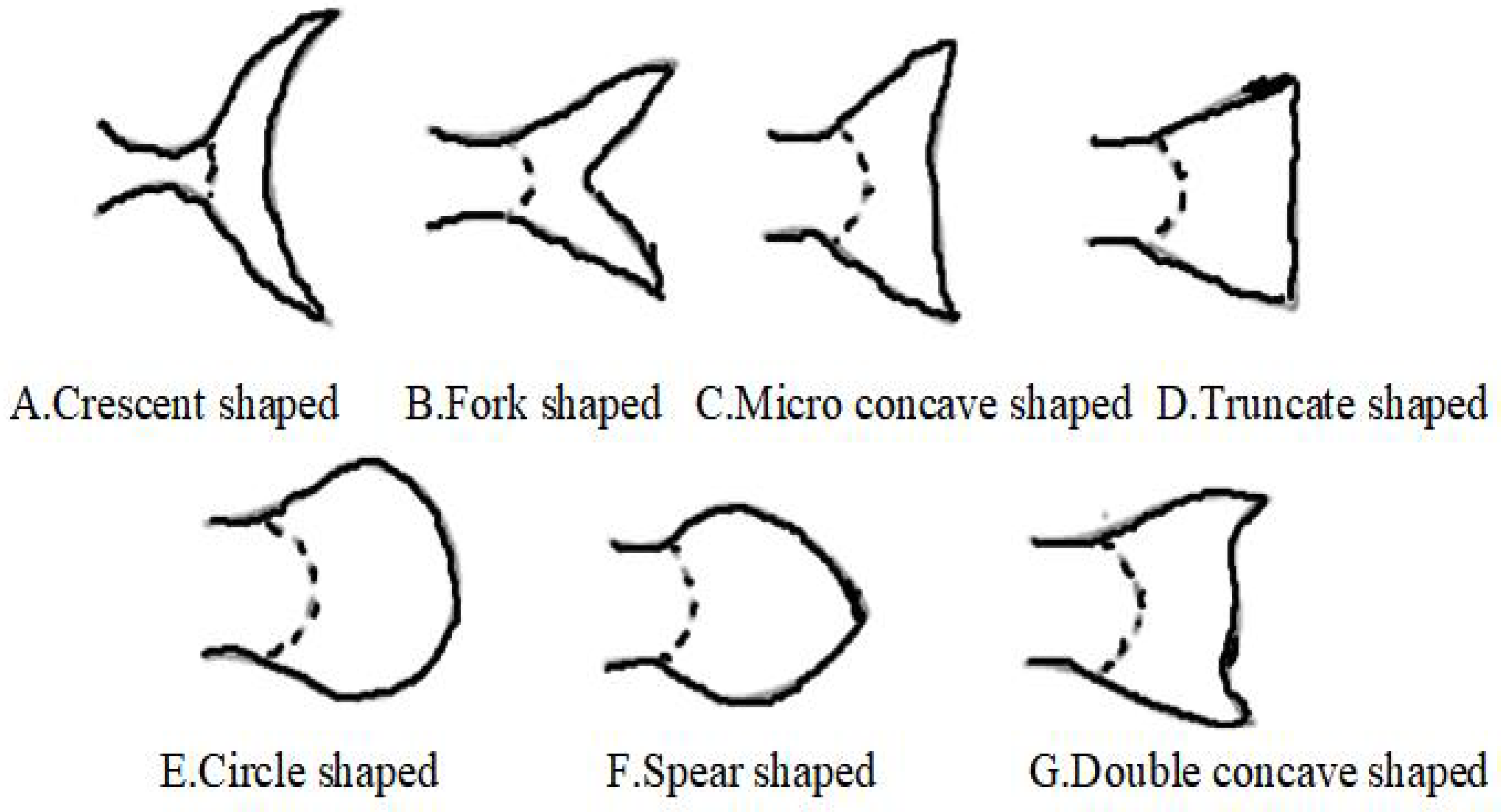
In this study, the forked tail fin (the second type) was chosen as the biomimetic model because its extended chord generates optimal thrust and power, making it ideal for efficient movement and maneuverability in the aquatic environment.
2.2. Fin Propulsion Mechanism
When fish swim, the back-and-forth oscillation of their fins generates a unique double-row vortex with opposite directions behind the fins, known as the anti-Kármán vortex street [23]. This vortex street phenomenon generates alternating jets, providing approximately 70% of the propulsion force for the fish. Research using DPIV (Digital Particle Image Velocimetry) technology has revealed this characteristic of the fish tail flow field, providing inspiration for the design of efficient propellers and underwater robots.
The Kármán vortex street is a key concept in fluid dynamics, which propels fish forward by forming interlocking vortices behind an object [24]. Its intensity is related to the oscillation force of the tail fin and can be measured by the Trauhal number, represented by the following formula:
T is the Trauhal number f is the Tail fin swing frequency b is the characteristic length (such as the tail fin length) is the kinematic viscosity of the surrounding fluid.
Figure 2.
The process of generating anti Karman vortex streets.
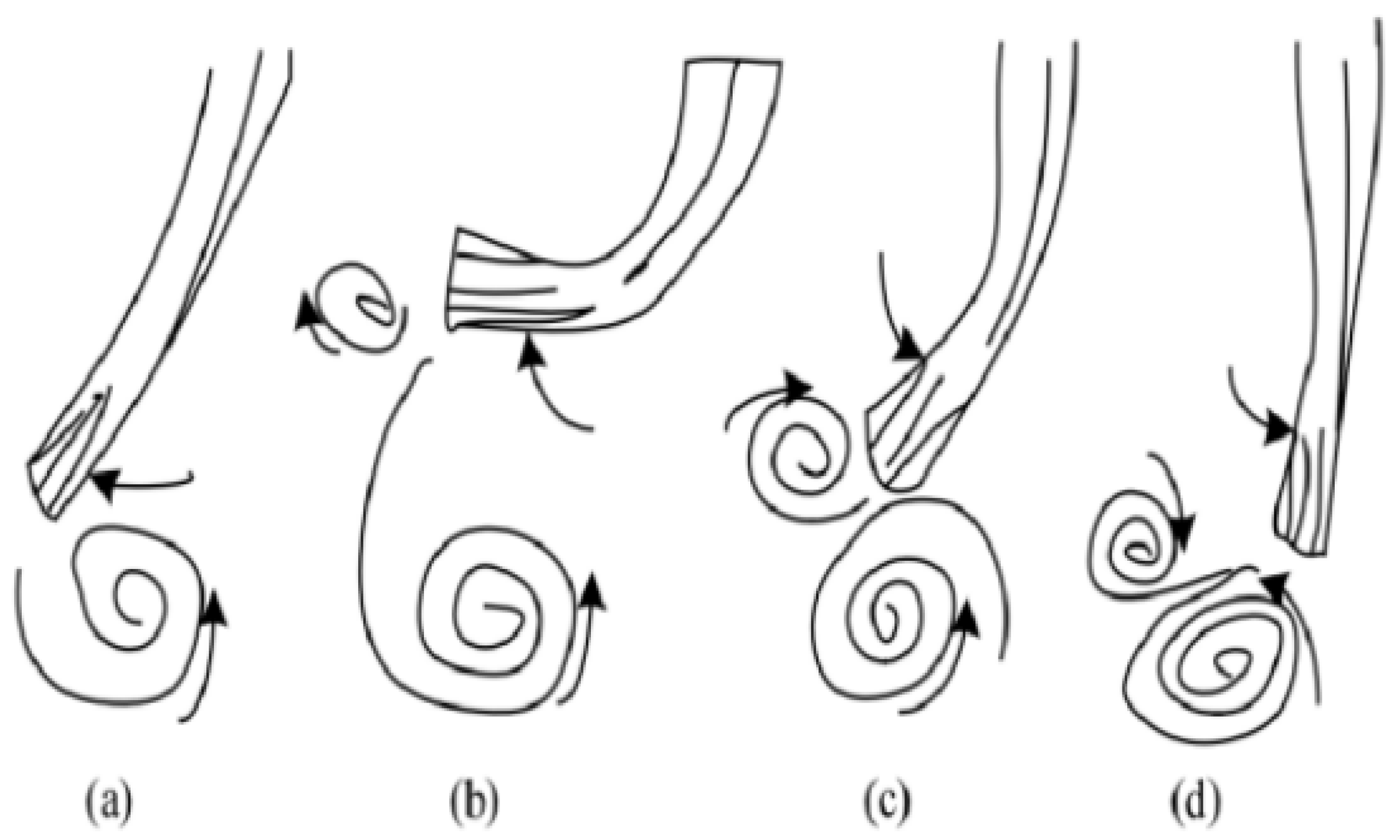
This formula indicates that the Trauhal number is directly proportional to both the tail fin oscillation frequency and the wake width, and inversely proportional to the swimming speed. That is, when the tail fin oscillation frequency or wake width increases, the Trauhal number increases, enhancing the anti-Kármán vortex street effect and providing greater propulsion. Conversely, as the swimming speed increases, the Trauhal number decreases, reducing the vortex street effect and propulsion.
2.3. Overall Design of the Control System
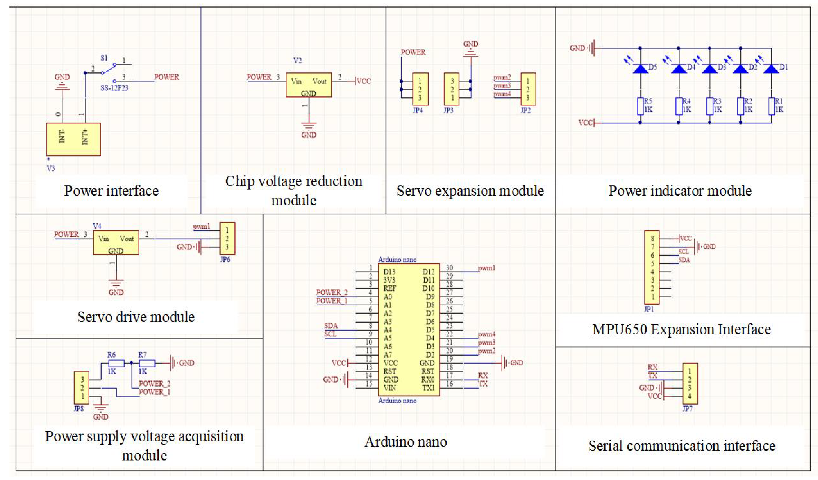
The design of the control system encompasses various aspects, including circuit sizing, hardware selection, and layout arrangement. Based on the functions of the biomimetic robotic fish, the control system is divided into ten components. These are the power interface, chip step-down voltage regulator module, servo motor driver, servo motor extension module, power display indicator module, Arduino chip, MPU6050 interface, and serial communication. The overall schematic diagram is shown in Figure 3.
Figure 3.
Overall schematic diagram of the circuit.
2.4. Multiple Servo Modules in Series
The design adopts a series connection of multiple servo modules, which greatly simplifies the mechanical structure of the robotic fish’s tail. The servos are connected in series, with the front servo driving the movement of the rear servos [25]. Each servo acts as a joint, similar to a joint in a real fish. Due to the size limitations of the servos, the number of joints is not very large. Typically, three to six joints can be simulated, depending on the specific dimensions. The standardization of servos allows for better economic efficiency, reliability, and stability when selecting them.
In terms of control, the servos are typically controlled by adjusting the duty cycle of the PWM (Pulse Width Modulation) signal [26]. In the processor, it is easy to implement the adjustment of multiple PWM duty cycles, significantly simplifying the complexity of control. Compared to the coupling of linkages, individual servo joints can be controlled independently, greatly improving the flexibility of control and allowing for movement that is more similar to that of real fish.
For the robotic fish tail’s motion, the multi-servo module series connection scheme is used, where each servo represents a vertebral joint of a real fish. The advantage of this approach is that the angle of each joint can be controlled precisely, offering high flexibility and motion characteristics that closely resemble those of real fish. The mechanism works by having the front joint drive the movement of the subsequent joints, with the final joint connecting to the tail fin to enable its swinging motion.
2.5. Head and Tail Fin Design
The design of the robotic fish head serves two main purposes. First, the shape must resemble that of a real fish, with a streamlined exterior to minimize drag and reduce friction [27]. Second, the internal space of the fish head is used to house components such as the circuit board, battery, and other modules that should not be exposed to water. The design must ensure sufficient space and secure placement for these components. Key considerations in the design include:First.Effectiveness and convenience of sealing: The sealing must ensure airtightness while being easy to install and maintain. To address this, waterproof servos and an integrated structural design are chosen.In addition.Underwater balance and center of gravity: The stability of the fish depends on the position of its center of gravity. A lower center of gravity improves stability, so heavy components should be placed as low as possible. Additionally, the left-right balance of the center of gravity must be maintained.
For the tail fin design, the shape should be based on the actual tail fin of a fish, aiming for optimal propulsion efficiency. it is important to base the shape on the natural tail fin of a fish in order to achieve optimal propulsion efficiency [28]. The tail fin plays a critical role in generating thrust and steering, and its shape significantly influences the hydrodynamics of the fish or robotic fish. The design of the tail fin must mimic the biological counterpart in a way that maximizes the thrust produced while minimizing drag, enabling efficient movement through the water.To digitally describe the tail fin, we use the concept of the aspect ratio, similar to the definition used for airplane wings. The aspect ratio of the tail fin is defined as:
In this equation L is the span (length of the fin), M is the tail fin area, is the aspect ratio.The tail fin area designed in this study is , , and the aspect ratio is .Meet the design requirements for propulsion performance.
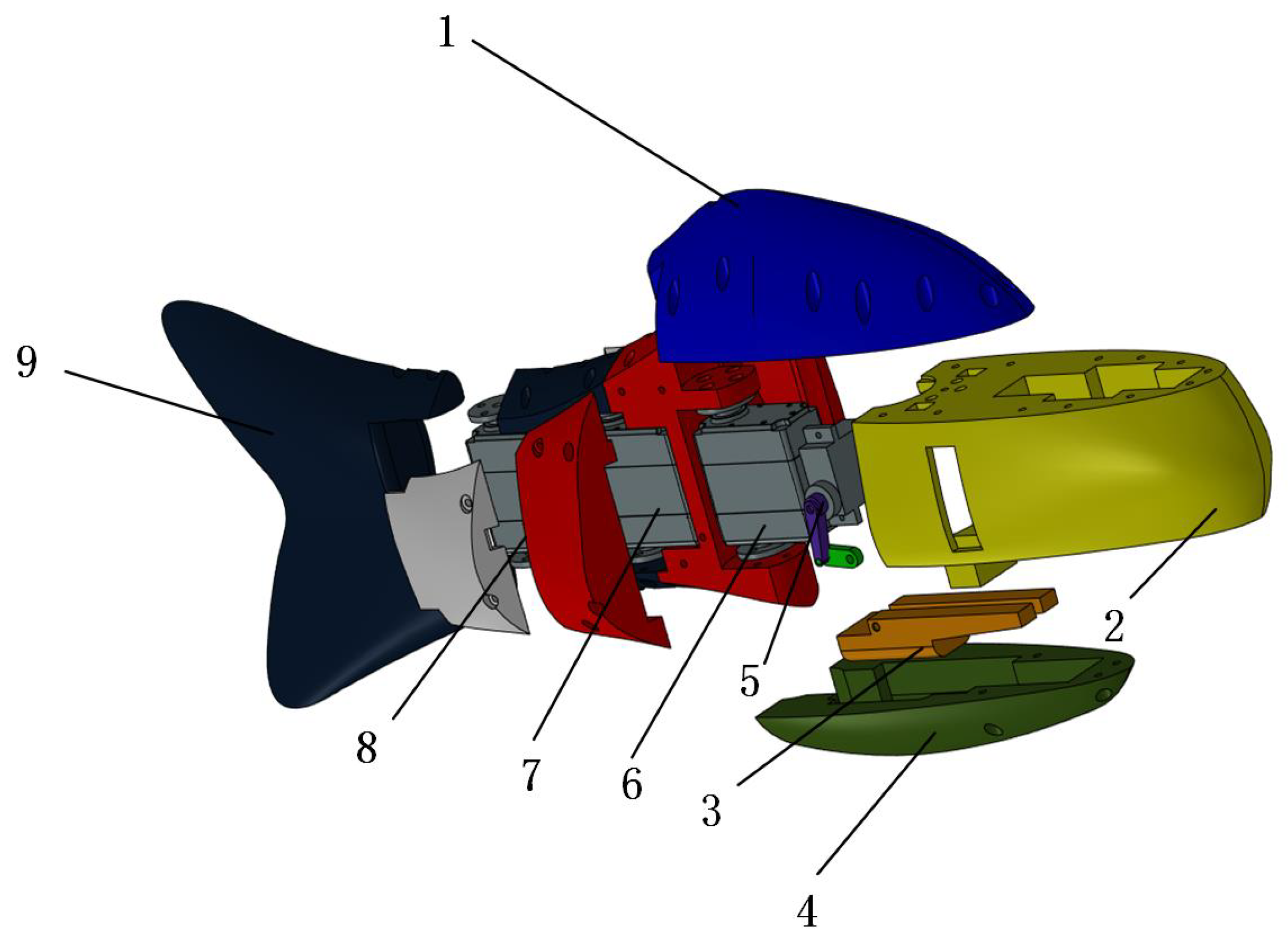
Figure 4.
The straight and turning movements of biomimetic fish(1. Control device 2. Battery compartment 3. Configuration module 4.3d Printing shell 5. Lift submersible servo 6-8. Three joint drive servo 9. Tail fin).
Figure 4.
The straight and turning movements of biomimetic fish(1. Control device 2. Battery compartment 3. Configuration module 4.3d Printing shell 5. Lift submersible servo 6-8. Three joint drive servo 9. Tail fin).
3. Results
3.1. Kinematic Model Establishment
To better understand and apply the swimming mechanism of the family Carangidae, this paper analyzes the swimming images of Carangidae species and studies their biomimetic design. This analysis led to the discovery of the fish body wave for the robotic fish. The fish body wave is a traveling wave that propagates from the head of the fish to the tail fin, with the amplitude gradually increasing. The curve equation can be described as:
Here is the lateral displacement (amplitude) of the fish body,x is the axial displacement of the fish body,k is the multiple of the wavelength of the fish body wave (, where is the wavelength), and are the linear and quadratic coefficients of the wave amplitude envelope, respectively, w is the frequency of the fish body wave, and is the period of the wave.
Figure 5.
Fish body fluctuation prediction.
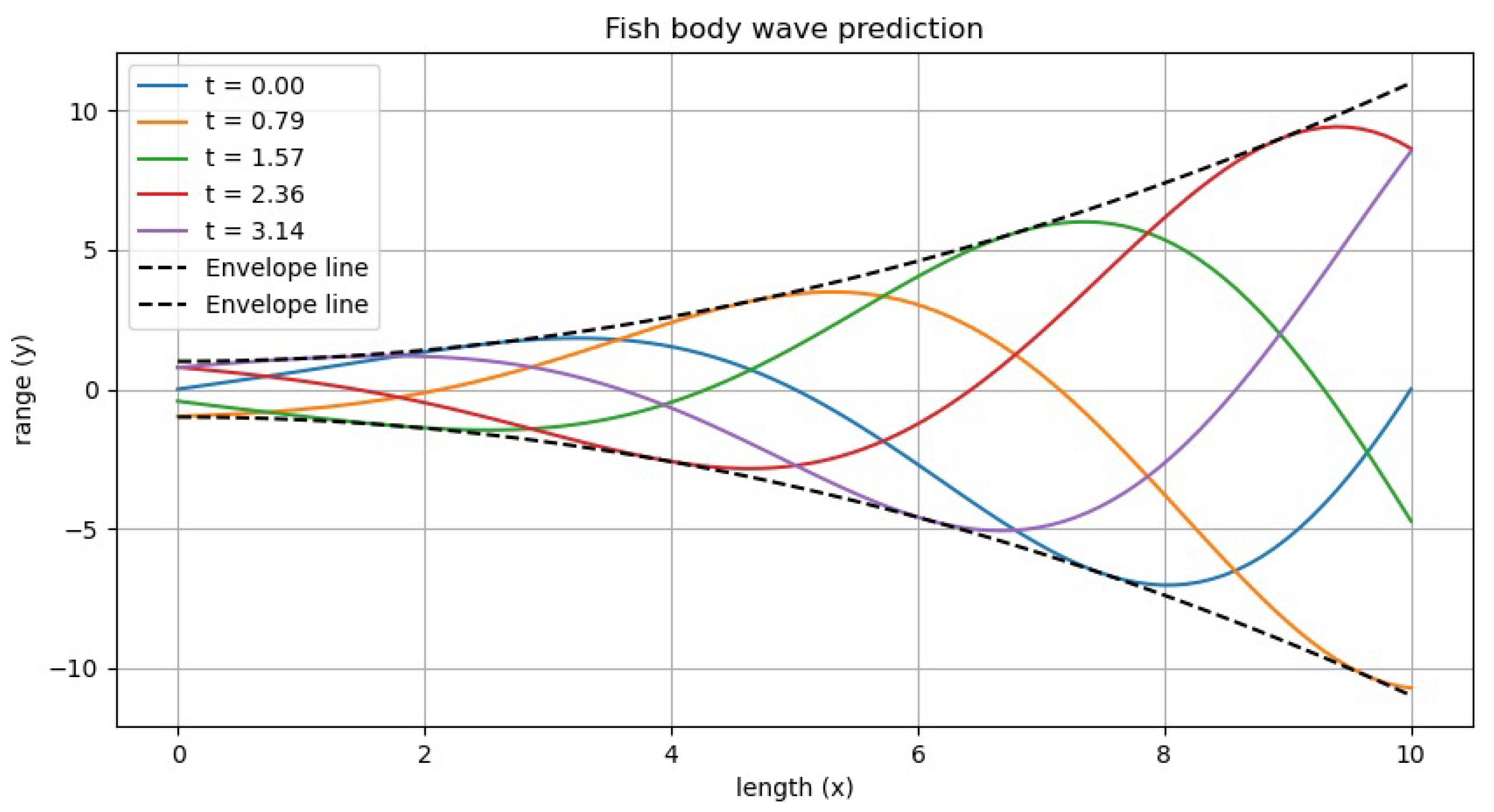
The fish body wave, joint shape, and angle information during motion are shown in Figure 7. In this figure:The x-axis represents the position along the fish body length, from the head to the tail (from 0 to 10), The y-axis represents the amplitude of the fish body oscillations at each position,Different colored curves represent the fish body oscillation states at different times t, including , showing how the fish body oscillations propagate from the head to the tail and how the amplitude gradually increases. The dashed lines in the figure represent the envelope of the fish body wave, indicating the maximum amplitude range of the oscillations. Figure 7 demonstrates how the fish body wave propagates over time, with the oscillations increasing in amplitude from the fish head to the tail, in line with the physical model of a biomimetic fish moving in water.Figure 7 also illustrates how the joints of the fish body change over time during straight-line swimming. It can be seen that the wave propagates from the head to the tail, with the amplitude gradually increasing, and the joints change accordingly. Through this model, it is possible to clearly understand the oscillations at various points along the fish body. The model covers the oscillatory characteristics of the fish body wave, the amplitude envelope, wavelength, frequency, and the shape and angle variations of the fish body joints.
3.2. System Testing and Experimentation
The ascent and descent motion of the robotic fish relies on the forward and backward movement of a ballast weight, which shifts the center of gravity, causing changes in the pitch angle of the fish. To conduct the experiment, the biomimetic robotic fish is placed stationary in water, and the pitch angle is measured using a gyroscope sensor. Data is returned at intervals of 0.1s.
By sending Bluetooth commands, the ballast weight is moved to the farthest position at the rear, and the resulting pitch angle is measured as . Then, a command is sent to move the ballast weight to the front, and the pitch angle is measured again, resulting in . The experimental data is shown in Figure 8. By varying the position of the ballast weight, the maximum pitch angle of (nose-up) and the minimum pitch angle of (nose-down) are observed. The actual maximum pitch angle for the robotic fish in one direction is:
The experimental results shown in Figure 8 validate the feasibility of the design that uses the forward and backward movement of the ballast weight to change the pitch angle of the biomimetic robotic fish. The change in pitch angle generates a vertical speed component, enabling the robotic fish to perform ascent and descent motion.
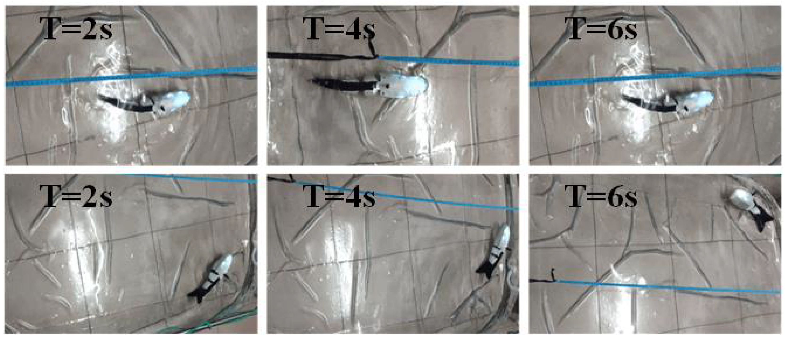
In order to verify the straight line and steering functions of the mechanical fish.First, the robotic fish is placed stationary in the water, and its swimming frequency is set to 2. After testing, it was observed that the fish traveled a distance of 150 mm in 8.2 seconds. The swimming speed of the robotic fish is calculated as:
After completing the forward motion experiment, the fish is returned to the starting position. The power is turned on, the fish’s body motion frequency is set to 0, and the fish is gently placed back into the water. The turning process is shown in Figure 10. After testing, it was found that the robotic fish took 12 seconds to complete a 180° turn. The turning radius was measured to be 45 cm, and the turning angular velocity was calculated as:
The straight and turning process of the robotic fish is illustrated in Figure 6.
Figure 6.
The straight and turning movements of biomimetic fish.
3.3. Application of On-Site Water Quality Monitoring
The bionic fish is equipped with various sensors, including temperature and humidity sensors, as well as water quality sensors [29]. The working principle diagram of the bionic fish is shown in Figure 7, where the water quality detection data is transmitted to the Arduino microcontroller platform and then sent via WiFi to the host computer for real-time monitoring [30].
Figure 7.
Water quality sampling points,A is the starting point and E is the endpoint.
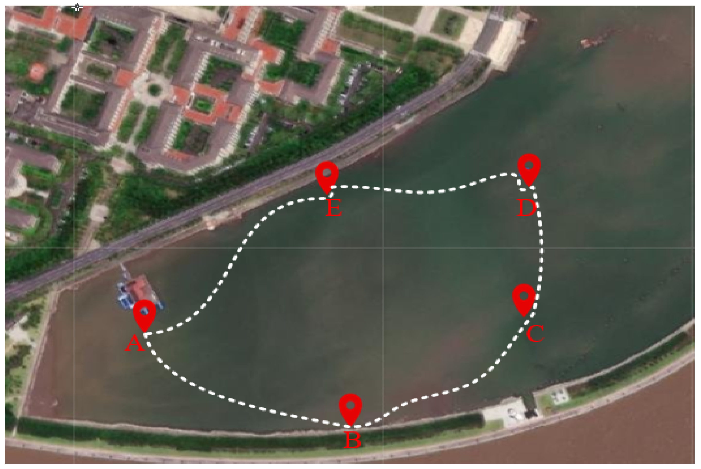
The experiment uses temperature, humidity, turbidity, and pH values as evaluation indicators. These parameters reflect the physical, chemical, and biological characteristics of the water, making them crucial for assessing water quality [31]. Through the investigation of water quality parameters, the concentration and distribution of various substances in the water can be monitored in real time, allowing for timely detection of pollution and the implementation of corrective measures [32,33]. The experimental location is shown in the figure. Five target points are set in the lake, and commands are sent via a mobile phone to direct the bionic fish to the designated locations for real-time water quality detection. Figure X illustrates the bionic fish performing the water quality sampling task on-site. Through the WiFi module, the water quality monitoring parameters are transmitted to the mobile interface, displaying real-time monitoring data.
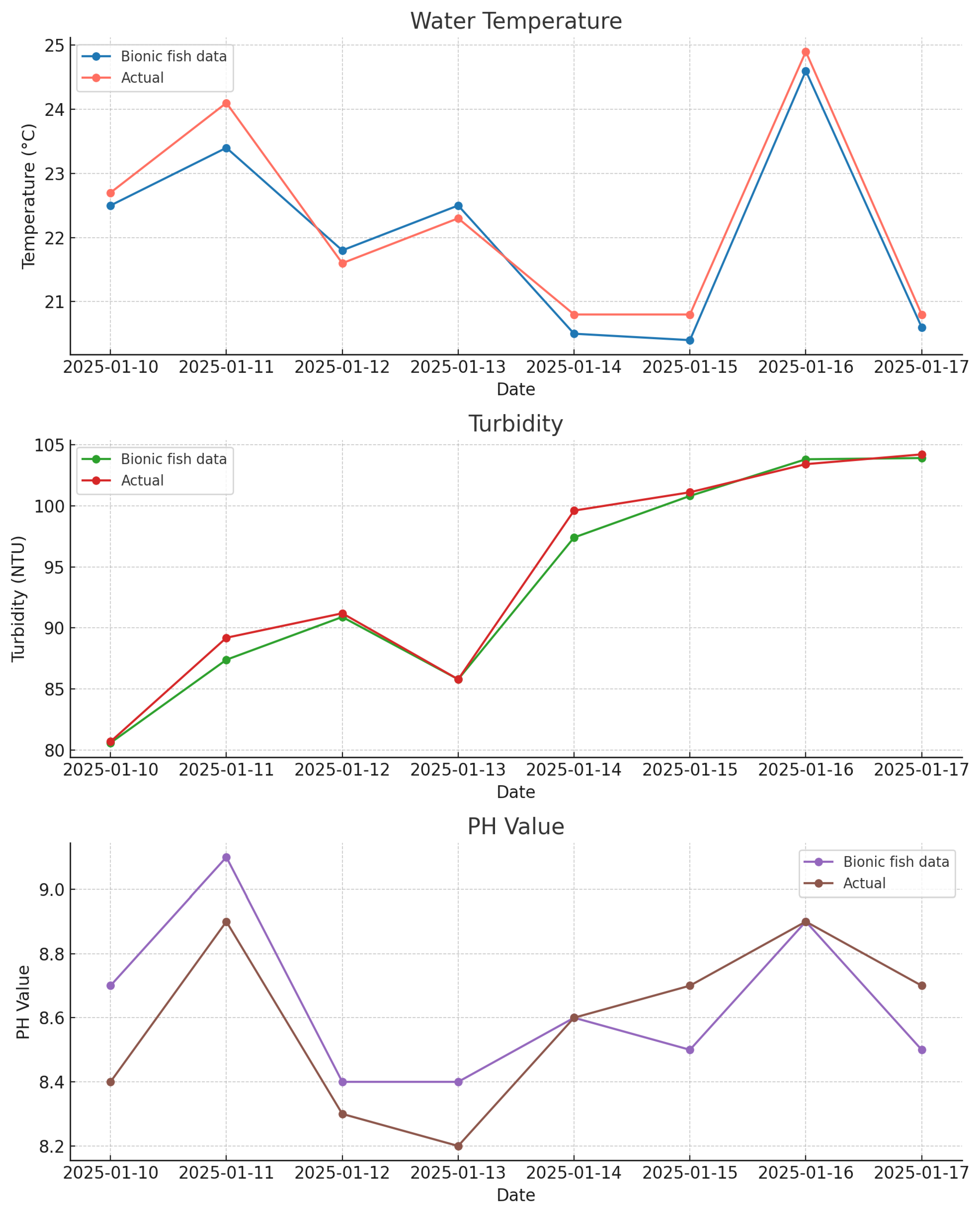
Compared with traditional water quality testing, the method proposed in this article has more concealment and maneuverability. However, there is a slight error between the collected data and the actual values, as shown in Table 1 of the experiment. This error may be caused by the accuracy error of the sensor itself and the sampling point environment.
Figure 8.
Water quality line chart.
4. Conclusions
This study presents the design, development, and experimental validation of a three-joint bionic fish based on the Body and Caudal Fin (BCF) model, aimed at improving the maneuverability and efficiency of bionic fish robots for enhanced inland water quality monitoring. The bionic fish features a forked tail fin that optimizes thrust and power, enabling efficient movement in aquatic environments. Experimental tests validated the design, demonstrating the bionic fish’s ability to perform key functions, including ascent, descent, straight-line swimming, and turning. It achieved a maximum pitch angle of 5.69°, a swimming speed of 0.018 m/s, and a turning angular velocity of 15°/s, confirming the feasibility of the system.Additionally, the bionic fish is equipped with sensors for temperature, humidity, turbidity, and pH, providing real-time water quality monitoring. The experiments confirmed the effectiveness of the robotic fish in collecting and transmitting water quality data. In conclusion, the three-joint bionic fish demonstrates significant potential for applications in environmental monitoring, marine research, and underwater exploration. By integrating advanced sensing technologies, it presents a promising solution for real-time, dynamic monitoring of aquatic environments. Future research will focus on enhancing its performance, particularly in terms of speed, maneuverability, and sensor accuracy, to expand its practical applications in diverse aquatic environments.
Author Contributions
Conceptualization, P.P.; methodology, P.P.; resources, P.P.; data curation, Y.B.J.; writing—original draft preparation, Y.B.J. and P.P.; project administration, P.P.; Y.B.J. and P.P. are the co-first authors. All authors have read and agreed to the published version of the manuscript.
Funding
This research was funded by Zhejiang Ocean University, grant number JX6311040123.
Data Availability Statement
The original contributions presented in this study are included in the article. Further inquiries can be directed to the corresponding author.
Conflicts of Interest
The authors declare that they have no known competing financial interests or personal relationships that could have appeared to influence the work reported in this paper.
References
- Aguzzi, J.; Costa, C.; Calisti, M.; Funari, V.; Stefanni, S.; Danovaro, R.; Gomes, H.I.; Vecchi, F.; Dartnell, L.R.; Weiss, P.; et al. Research Trends and Future Perspectives in Marine Biomimicking Robotics. Sensors 2021, 21. [CrossRef]
- Zimmerman, S.; Abdelkefi, A. Review of marine animals and bioinspired robotic vehicles: Classifications and characteristics. Progress in Aerospace Sciences 2017, 93, 95–119. [CrossRef]
- Wang, R.; Wang, S.; Wang, Y.; Cheng, L.; Tan, M. Development and Motion Control of Biomimetic Underwater Robots: A Survey. IEEE Transactions on Systems, Man, and Cybernetics: Systems 2022, 52, 833–844. [CrossRef]
- Huang, Y.; Wang, X.; Xiang, W.; Wang, T.; Otis, C.; Sarge, L.; Lei, Y.; Li, B. Forward-Looking Roadmaps for Long-Term Continuous Water Quality Monitoring: Bottlenecks, Innovations, and Prospects in a Critical Review. Environmental Science & Technology 2022, 56, 5334–5354. [CrossRef]
- Chen, X.; Li, D.; Mo, D.; Cui, Z.; Li, X.; Lian, H.; Gong, M. Three-Dimensional Printed Biomimetic Robotic Fish for Dynamic Monitoring of Water Quality in Aquaculture. Micromachines 2023, 14. [CrossRef]
- Zhang, D.; Huang, Q.; Xu, H.; Zhu, H.; Cao, Y.; Cao, Y.; Pan, G. Development and three-dimensional modeling of a bionic robotic fish with pectoral fins. Ocean Engineering 2025, 321, 120393. [CrossRef]
- Xia, Q.; Li, H.; Song, N.; Wu, Z.; Wang, X.; Sun, X.; Zhang, S.; Yang, C. Research on flexible collapsible fluid-driven bionic robotic fish. Ocean Engineering 2023, 276, 114203. [CrossRef]
- Cui, Z.; Li, L.; Wang, Y.; et al. Review of research and control technology of underwater bionic robots. Intelligent Marine Technology and Systems 2023, 1, 7. [CrossRef]
- Chen, K.; Zhu, W.; Dou, L. Research on Mobile Water Quality Monitoring System Based on Underwater Bionic Robot Fish Platform. In Proceedings of the Proceedings of the 2020 IEEE International Conference on Advances in Electrical Engineering and Computer Applications (AEECA), Dalian, China, August 25–26 2020; pp. 158–163.
- Liu, G.; Liu, S.; Xie, Y.; Leng, D.; Li, G. The analysis of biomimetic caudal fin propulsion mechanism with CFD. Applied Bionics and Biomechanics 2020, 2020, 7839049. [CrossRef]
- Liu, H.; Zhou, Y.; Ren, X.; Liu, S.; Liu, H.; Li, M. Numerical modeling and application of the effects of fish movement on flow field in recirculating aquaculture system. Ocean Engineering 2023, 285, 115432. [CrossRef]
- Unknown, A. Three-Dimensional Printed Biomimetic Robotic Fish for Dynamic Monitoring of Water Quality in Aquaculture. Micromachines 2023, 14. [CrossRef]
- Kai, C.; Weiwei, Z.; Lu, D. Research on Mobile Water Quality Monitoring System Based on Underwater Bionic Robot Fish Platform. In Proceedings of the 2020 IEEE International Conference on Advances in Electrical Engineering and Computer Applications( AEECA), 2020, pp. 457–461. [CrossRef]
- Chen, X.; Li, D.; Mo, D.; Cui, Z.; Li, X.; Lian, H.; Gong, M. Three-Dimensional Printed Biomimetic Robotic Fish for Dynamic Monitoring of Water Quality in Aquaculture. Micromachines 2023, 14, 1578. [CrossRef]
- Cai, Y.; Bi, S.; Li, G.; Hildre, H.P.; Zhang, H. From Natural Complexity to Biomimetic Simplification: The Realization of Bionic Fish Inspired by the Cownose Ray. IEEE Robotics & Automation Magazine 2019, 26, 27–38. [CrossRef]
- Cui, Z.; Li, L.; Wang, Y.; Zhong, Z.; Li, J. Review of research and control technology of underwater bionic robots. Intelligent Marine Technology and Systems 2023, 8, 45–58. [CrossRef]
- Duraisamy, P.; Kumar Sidharthan, R.; Nagarajan Santhanakrishnan, M. Design, modeling, and control of biomimetic fish robot: A review. Journal of Bionic Engineering 2019, 16, 967–993. [CrossRef]
- Ji, Y.; Wei, Y.; Liu, J.; An, D. Design and Realization of a Novel Hybrid-Drive Robotic Fish for Aquaculture Water Quality Monitoring. Journal of Bionic Engineering 2023, 20, 543–557. [CrossRef]
- Liu, Y.; Jiang, H. Research development on fish swimming. Chinese Journal of Mechanical Engineering 2022, 35, 114. [CrossRef]
- Lu, Y.; Cao, Y.; Pan, G.; Huang, Q.; Dong, X.; Cao, Y. Effect of cross-joints fin on the thrust performance of bionic pectoral fins. Chinese Journal of Mechanical Engineering 2022, 10, 869. [CrossRef]
- Ou, H.; Yuan, Y.; Feng, J. CFD-based hydrodynamic analysis of bionic fish. International Journal of New Developments in Engineering and Society 2023, 7, 55–59. [CrossRef]
- Sun, B.; Li, W.; Wang, Z.; Zhu, Y.; He, Q.; Guan, X.; Dai, G.; Yuan, D.; Li, A.; Cui, W. Recent progress in modeling and control of bio-inspired fish robots. Journal of Marine Science and Engineering 2022, 10, 773. [CrossRef]
- Zhong, Y.; Li, Z.; Du, R. A novel robot fish with wire-driven active body and compliant tail. IEEE/ASME Transactions on Mechatronics 2017, 22, 1633–1643.
- Tong, X.; Tang, C. Design of a monitoring system for robotic fish in underwater environment. International Journal of Vehicle Information and Communication Systems 2018, 3, 321.
- Wang, Z.; Wang, L.; Wang, T.; Zhang, B. Research and experiments on electromagnetic-driven multi-joint bionic fish. Robotica 2022, 40, 720–746. [CrossRef]
- Wu, R.; Du, G.; Liu, Z.; Zhang, D.; Yu, Y. Design of Bionic Robot Fish Propelled by Two Joint Caudal Fin. In Proceedings of the Journal of Physics: Conference Series, 2021, Vol. 1982, p. 12056. [CrossRef]
- Lyons, K.J.; Ikonen, J.; Hokajärvi, A.M.; Räsänen, T.; Pitkänen, T.; Kauppinen, A.; Kujala, K.; Rossi, P.M.; Miettinen, I.T. Monitoring groundwater quality with real-time data, stable water isotopes, and microbial community analysis: A comparison with conventional methods. Science of the Total Environment 2023, 864, 161199.
- Yan, Z.; Yang, H.; Zhang, W.; Lin, F.; Gong, Q.; Zhang, Y. Bionic fish tail design and trajectory tracking control. Ocean Engineering 2022, 257, 111659. [CrossRef]
- Zhang, L. Design of a Multi-Joint Tail Fin Driven Bionic Robotic Fish and Its Hydrodynamic Analysis. In Proceedings of the Proceedings of the International Conference on Mechanical Design and Simulation (MDS 2022), Wuhan, China, August 21–23 2022; pp. 822–828.
- Li, C.; Song, Y.Z.; Si, H.M. Development and implementation of an advanced shipborne integrated platform for water quality inspection. Frontiers in Marine Science 2024, 11. [CrossRef]
- Cao, P.; Zhu, Y.; Zhao, W.; Liu, S.; Gao, H. Chromaticity Measurement Based on the Image Method and Its Application in Water Quality Detection. Water 2019, 11. [CrossRef]
- Hu, W.C.; Chen, L.B.; Wang, B.H.; Li, G.W.; Huang, X.R. Design and Implementation of a Full-Time Artificial Intelligence of Things-Based Water Quality Inspection and Prediction System for Intelligent Aquaculture. IEEE Sensors Journal 2024, 24, 3811–3821. [CrossRef]
- Wang, L.; Dong, H.; Cao, Y.; Hou, D.; Zhang, G. Real-time water quality detection based on fluctuation feature analysis with the LSTM model. Journal of Hydroinformatics 2023, 25, 140–149, [https://iwaponline.com/jh/article-pdf/25/1/140/1258947/jh0250140.pdf]. [CrossRef]

Table 1.
Water quality monitoring sampling data.
| Date | Water Temp | Turbidity | PH Value | |||
|---|---|---|---|---|---|---|
| Bionic Fish Data | Actual | Bionic Fish Data | Actual | Bionic Fish Data | Actual | |
| 2025-01-10 | 22.5 | 22.7 | 80.6 | 80.7 | 8.7 | 8.4 |
| 2025-01-11 | 23.4 | 24.1. | 87.4 | 89.2 | 9.1 | 8.9 |
| 2025-01-12 | 21.8 | 21.6 | 90.9 | 91.2 | 8.3 | 8.5 |
| 2025-01-13 | 22.5 | 22.3 | 85.8 | 85.8. | 8.4 | 8.2 |
| 2025-01-14 | 20.5 | 20.4 | 97.4 | 99.6 | 8.1 | 8.2 |
| 2025-01-15 | 20.4 | 20.8 | 100.8 | 101.1 | 8.3 | 8.6 |
| 2025-01-16 | 24.6 | 24.9 | 103.8 | 104.1 | 8.9 | 8.9 |
| 2025-01-17 | 20.6 | 20.8 | 103.9 | 104.2 | 8.5 | 8.7 |
Disclaimer/Publisher’s Note: The statements, opinions and data contained in all publications are solely those of the individual author(s) and contributor(s) and not of MDPI and/or the editor(s). MDPI and/or the editor(s) disclaim responsibility for any injury to people or property resulting from any ideas, methods, instructions or products referred to in the content. |
© 2025 by the authors. Licensee MDPI, Basel, Switzerland. This article is an open access article distributed under the terms and conditions of the Creative Commons Attribution (CC BY) license (http://creativecommons.org/licenses/by/4.0/).
Copyright: This open access article is published under a Creative Commons CC BY 4.0 license, which permit the free download, distribution, and reuse, provided that the author and preprint are cited in any reuse.


