
Submitted:
05 May 2023
Posted:
06 May 2023
You are already at the latest version
Abstract
To study the strengthening effect on recycled concrete columns by carbon fiber composite materials (CFRP) under different levels of seismic damage, four column specimens were designed for pseudo-static tests. The four specimens were respectively non-destructive without strengthening (prototype), non-destructive strengthening, medium seismic damage strengthening and severe seismic damage strengthening, according to the replacement rate of recycled aggregates and the level of seismic damage. The characteristics of the deformation damage and seismic performance indicators of each specimen were compared and analyzed. A decrease was observed in the initial stiffness of the seismically damaged recycled concrete column specimens strengthened with CFRP, while the ductility, peak bearing capacity and energy dissipation capacity of the specimens were improved. On the other hand, with the reduction of seismic damage and the increase of recycled aggregate replacement rate, the ductility and energy dissipation capacity of the reinforced seismic damaged recycled concrete column specimens were enhanced to different levels. In particular, the cumulative energy consumption of the strengthened specimens under medium seismic damage increased most significantly by 32.5%. In general, the hysteretic curves of the strengthened specimens were full, and the average ductility coefficients were 4.1–6.8. CFRP strengthening was more effective in restoring and enhancing the performance of the recycled concrete column specimens with medium and lower seismic damage levels (displacement ratio ≤ 3%).
Keywords:
carbon fiber composites
; recycled concrete
; recycled aggregate replacement rate
; levels of seismic damage
; pseudo-static test
1. Introduction
With the construction pace of civil engineering in China accelerating, there is a severe shortage of building materials, particularly concrete. However, the amount of waste concrete produced by the demolition of old structures is growing and seriously polluting the environment. Using recycled concrete made of waste concrete can effectively address the issues of pollution of environment and shortage of the building materials[1,2,3]. Therefore, the recycled concrete has a wide range of potential applications in the construction of civil engineering. On the other hand, China is a vast country with many earthquakes[4]. Load-bearing elements such as columns are highly susceptible to seismic damage during their service life[5]. The repair and strengthening of seismically damaged column elements has been a key direction of research. Summarizing the research in the repair and strengthening fields in recent years, it is found that external clad steel strengthening[6], increased section method strengthening[7] and CFRP strengthening[8,9,10] are the commonly used methods of strengthening seismic damaged elements. Among them, CFRP strengthening has been widely used in the repair and strengthening of structural components because of its high strength, no increase in structural self-weight, good durability, and easy construction[11,12,13]. The CFRP strengthening method can make up for some performance defects of concrete structures and effectively extend the service life of damaged structures[14,15,16,17,18,19,20].
Studies by Donghui Cheng and Changdong Zhou[21,22,23,24,25] pointed out that in CFRP strengthening, the height of the strengthening, the method of adhesion, and the location of the adhesion all play significant effects on the strengthening of the seismically damaged members elements. The seismic performance of the specimen increases with the number of strengthening layers and the height of the strengthening. The seismic performance of seismically damaged elements strengthened by a combination of longitudinal and transverse CFRP adhesives is superior. Chunling Lu[26] investigated the effects of reinforcement ratio, hoop ratio and shear-to-span ratio on the seismic performance of prestressed CFRP strengthened reinforced concrete square column by experiments, and found that increasing the reinforcement ratio and hoop ratio is beneficial to improve the deformation and energy dissipation capacity of the strengthened column, and the strengthening effect is better when the CFRP cloth restraint range completely covers the plastic hinge area. Ozcan[27] et al. analyzed the effect of axial load and CFRP fillet radius on the reinforcement effect of reinforced concrete columns, and the results showed that CFRP can effectively improve the ductility, energy dissipation capacity and shear stiffness of the specimens. Chen Jun[28] investigated the seismic performance of short columns of CFRP strengthened with CFRP and analyzed the effects of the number of CFRP strengthening layers and axial compression ratio on the seismic performance of the strengthened specimens. It was found that the ductility and energy dissipation capacity of the short columns with CFRP strengthening were significantly improved and brittle damage was effectively avoided. Kowalsky[29] et al classified the RC column properties as usable (no need to repair) and limited damage (repairable), and used The limits of each limit state index of RC column are given by using the tensile strain of reinforcement and compressive strain of concrete as the property index.
In summary, the above research provides theoretical base for the study of CFRP strengthening of seismic damaged components, but there are few cases of using CFRP in the study of strengthening recycled concrete damaged components[30,31,32,33,34]. Most of the researchers conducted the pre-damage treatment of test elements with rough determination of their seismic damage level. Further classification of the seismic damage level of the test elements need to be defined. The strengthening effect of CFRP on structural components with different seismic damage levels need to be studied. In this paper, four recycled concrete columns were constructed and loaded with pre-damage treatment, and the four columns were non-destructive without strengthening (prototype), non-destructive strengthening, medium seismic damage strengthening, and severe seismic damage strengthening according to their seismic damage level. Pseudo-static tests of the four recycled concrete column strengthened with CFRP were carried out. By comparing the experimental data of the four columns, the corresponding seismic performance indexes were analyzed. The advantages of CFRP strengthening method under different levels of seismic damage were explored.
2. General situation of test
2.1. Specimen design and material parameters
The four recycled concrete column specimens were loaded to achieve specific damage states. According to the level of seismic damages, the four specimens were non-destructive without strengthening (prototype), non-destructive with strengthening, medium seismic damage with strengthening and severe seismic damage with strengthening. The four specimens were named as RC0, RRC1, RRC2 and RRC3, and their detailed parameters are shown in Table 1.
The maximum particle size of recycled aggregate used in the specimens was 25 mm, and the water absorption of the recycled aggregate was 3.8%. CL0 was the control concrete with natural aggregate (0% recycled aggregate replacement), and CL50 was the concrete with 50% recycled aggregate replacement. The concrete material ratios are shown in Table 2. Concrete material performance parameters were obtained from material properties experiments and are shown in Table 3.
The geometric dimensions and reinforcement of the four specimens are the same. Take RC0 as an example, the design schematic is shown in Figure 1. The cross-sectional diameter of the column is 300mm, the height of the column is 1050mm, the cross-sectional size of the column head is 400mm×400mm, and the cross-sectional size of the specimen cap is 400mm×700mm. The longitudinal reinforcement and the hoop reinforcement are both HRB400 steel bars with diameters of 12mm and 8mm respectively. The material property parameters of the reinforcement were obtained from the material property test, as shown in Table 4.
The mechanical properties of the high-strength grout used in the strengthening process of the damaged recycled concrete columns were tested according to the test method of concrete materials. The measured cubic compressive strength of the grout was 68.41 MPa. The material mechanical parameters of CFRP, impregnating adhesive and crack repair and leveling adhesive are shown in Table 5.
2.2. Seismic damage control and specimen strengthening
The simulation and control of the seismic damage states of the specimens were mainly achieved by pre-damage treatment. The damage caused by the earthquake was simulated by loading the specimen repeatedly at low circumference[35,36]. The level of seismic damage was determined based on the test phenomena and data of the specimen loading. The guidelines are summarized as follows: the initial state of the specimen is non-destructive; the state when the crack width of the specimen reaches 1~2 mm and the beginning of concrete spalling is defined as the medium seismic damage state; the state when the concrete spalling of the specimen is large, the reinforcement is exposed and the horizontal bearing capacity of the specimen reaches the peak value and enters the descending section is defined as the severe seismic damage state[37,38,39]. Consequently, the pre-damage loading displacement of the column specimen in the medium seismic damage state is 36 mm (displacement ratio 3%), as shown in Figure 2a. The per-damage loading displacement in the state of severe seismic damage is 54 mm (displacement ratio 4.5%), as shown in Figure 2b, and the pre-damage parameters of each specimen are shown in Table 6.
After pre-damage treatment and cleaning of the damaged parts, the damaged parts were filled with high-strength grout and crack repair adhesive and maintained for 48h. Then the seismic damaged parts were repaired and strengthened with CFRP and impregnating adhesive. The strengthening height of CFRP was 60 cm according to the crack distribution of the specimens after pre-loss loading. The adhesive form of CFRP was in the form of plastic hinge reinforcement by combining transverse hoop and longitudinal paste.
2.3. Loading device and loading system
The test loading device is shown in Figure 3. The specimen cap was rigidly anchored to the ground by high strength bolts. When the test was carried out, the vertical load was applied to the top of the column by a hydraulic jack. The design axial pressure ratio is 0.2. The horizontal load on the top of the specimen was applied by an electro-hydraulic servo actuator.
The loading system used full displacement control loading. The loading amplitude was 6 mm, and each loading cycle was performed 3 times. The first four levels of loading were shown in Figure 4. When the bearing capacity of the specimen was reduced to 85% of the maximum horizontal load or when the reinforcement was pulled out and the core concrete was crushed in a large area, the loading was stopped.
2.4. Analysis of test phenomena
The damage phenomena of the non-strengthened and strengthened specimens at final load moment are shown in Figure 5 and Figure 6.
Summarizing the test phenomena of each specimen loading process, in the elastic phase, there was no obvious deformation of each specimen, and the reinforcement and concrete maintained elastic working condition. In the yielding stage, with the increase of the number of cycles, concrete cracking and slight spalling appeared on both sides of the non-strengthened specimens, as shown in Figure 5a. The strengthened specimen showed slight bulge on the compressed side, and there was no obvious change on the tensile side, but a slight sound of CFRP tearing could be heard. When the horizontal displacement was loaded in reverse, the original compressed side became the tensile side, and cracks appeared at the junction of the column bottom and the specimen cap, as shown in Figure 6a, and the overall deformation of the specimen was gradually becoming obvious. As the loading continued, the concrete cracking and spalling on both sides of the non-strengthened specimen became more serious. The cracking at the bottom of the column of the strengthened specimen was obvious. The compression side was clearly bulging outwards, and the cracking of the CFRP on the tensioned side was clearly visible. The cracks were gradually developed due to the accumulation of damage, and finally, the concrete spalling of the non-strengthened specimen was serious and the longitudinal tendons and hoops were exposed, as shown in Figure 5b. For the strengthened specimen, through cracks formed at the junction of column bottom and specimen cap, and the surrounding concrete was crushed, and the CFRP continued to tear, as shown in Figure 6b. Eventually, the bearing capacity of the specimens dropped sharply and were completely destroyed.
3. Analysis of test results
3.1. Hysteretic curve
The measured hysteretic curves of each specimen are shown in Figure 7.
The hysteresis curves of the column specimens had some commonalities (Figure 7). At the initial stage of loading, the specimens were in an elastic state. The area enclosed by the hysteresis curve was small, the energy consumption capacity of the specimen was weak. The stiffness degradation and residual deformation were not obvious. As the loading proceeding, the area enclosed by the hysteresis curve gradually increased, the energy consumption capacity increased, and the stiffness degradation and residual deformation were more obvious. In general, the hysteresis curves of the recycled concrete column specimens strengthened by severe seismic damage were narrower and longer.
3.2. Skeleton curve
The comparative skeleton curves of each specimen are shown in Figure 8. The skeleton curves of the four specimens were basically similar in shape, and all included rising section, peak point and falling section. Compared to the prototype specimen, the initial stiffness of the damaged strengthened specimens decreased, the yield displacement increased. The damaged strengthened specimens entered the yield state later than the prototype specimens with a larger difference in the location of the peak point. The yield displacements of the damaged strengthened specimens were relatively close to each other, and the bearing capacity had a long rising phase. Overall, the bearing capacity of the strengthened recycled concrete column specimen with severe seismic damage decreased most rapidly after reaching the peak load.
We use the "furthest point" method[40] to determine the yield point, peak point and limit point of the skeleton curve, which are shown in Figure 9.
The relevant indexes corresponding to the yield point, peak point and limit point of the skeleton curve were shown in Table 7. Compared to RC0, the peak bearing capacity of RRC1, RRC2, RRC3 increased by 14.3%, 11.4% and 1.19%, respectively. The yield displacement of RRC1, RRC2, RRC3 increased by 0.4%, 52.9% and 76.1%, respectively. The limit displacement of RRC1, RRC2, RRC3 increased by 10.7%, 26.3% and 15.9%, respectively. The peak load bearing capacity of RRC2 is increased 10.1% compared to RRC3. Therefore, CFRP had a significant effect on the recovery of the bearing capacity and ductility of the damaged recycled concrete columns. The level of seismic damage had a significant effect on the strengthening effect of CFRP.
3.3. Displacement ductility factor
The displacement ductility factor of the specimen is calculated with the ratio of the ultimate displacement and the yield displacement , as shown in equation (1):
The displacement ductility coefficients of the specimens are shown in Table 8. The average displacement ductility coefficients of strengthened specimens were concentrated between 4.1 and 6.8. The average displacement ductility coefficient of non-destructive strengthened specimen RRC1 was increased by 10.2% compared to that of the prototype RC0. The average displacement ductility coefficients of RRC2 and RRC3 reached 82.5% and 67.1% of that of RC0, respectively. The average displacement ductility coefficient of RRC2 was 22.9% higher than that of RRC3. The ductility of the recycled concrete column specimens with different seismic damages recovered and improved to different levels after the CFRP strengthening. The more severe the seismic damage of the specimens, the weaker the effect of CFRP on the recovery and improvement of the ductility of the specimens. In general, CFRP had better ductility recovery and improvement for specimens with medium and lower seismic damage levels.
3.4. Strength degradation
The strength degradation of the specimen is measured by the strength degradation factor η. The strength degradation factor η is defined as the ratio of the peak bearing capacity of the last cycle of the displacement to the peak bearing capacity of the first cycle. It is calculated according to Equation (2).
Where is the peak bearing capacity of the first cycle of the i-th displacement stage and is the peak bearing capacity of the last cycle of the i-th displacement stage. The strength degradation curve of each specimen is shown in Figure 10. On the whole, the strength degradation coefficients of each specimen were concentrated between 0.9 and 1.0.
The bearing capacities of the four specimens were generally degraded with the loading. RRC1, RRC2 and RRC3 were more stable in bearing capacity even if the horizontal displacement increases before reaching the peak load. The bearing capacity degradation curve was relatively smooth and showed good ductility, which indicating that CFRP had a good strengthening effect on the recycled concrete column specimens with different levels of seismic damage under large lateral displacement conditions (Figure 9). After reaching the peak load, the bearing capacity of RRC2 and RRC3 degraded more rapidly, which may be due to the bulging and tearing of the outsourced CFRP and the weakening of the restraint on the concrete in the core area. In general, the level of seismic damage of the recycled concrete column specimens had a large influence on the strength degradation coefficient. The lower the initial seismic damage of the specimens, the more stable the CFRP strengthened bearing capacity was and the easier it was to maintain the strength.
3.5. Stiffness degradation
Stiffness degradation is characterized by the average secant stiffness in the positive and negative directions at all levels of the hysteretic curve, as shown in Equation 3.
Where represents the average value of peak load in positive and negative directions for each stage, and represents the average value of maximum displacement in positive and negative directions for each stage.
The stiffness degradations of the four specimens are shown in Figure 11.
The stiffness degradations of the four specimens were similar as the load proceeding (Figure 11). With the displacement increases, the stiffness becomes smaller. The initial stiffness of RC0 was 6.61 kN/mm. The initial stiffness of RRC1 was 7.85 kN/mm, RRC2 was 6.03 kN/mm, and RRC3 was 4.55 kN/mm. The more severe the seismic damage, the lower the initial stiffness. The CFRP strengthening did not significantly enhance the initial stiffness of the specimens. As the load proceeding, the stiffness degradation of the specimens slowed down,which indicating that the effect of CFRP on the stiffness of the recycled concrete column specimens with seismic damage will gradually appear as the loa proceeding. Overall, the stiffness improvement was most significant after strengthening of non-destructive recycled concrete column specimens. The stiffness of the medium seismic damage recycled concrete column would be effectively improved and restored after strengthening. The stiffness was recovered but not significantly after strengthening of severe damage recycled concrete column. The stiffness restoration and improvement of damaged recycled concrete columns strengthening with CFRP were more evident for the medium damage and non-damage recycled concrete columns.
3.6. Energy consumption capacity
The energy consumption capacity of the specimen is mainly determined by the equivalent viscous damping coefficient and the accumulated energy consumption.
The equivalent viscous damping coefficients of the specimens are shown in Figure 12. The equivalent viscous damping coefficients of the specimens showed an increasing trend. In most of the loading stages, the equivalent viscous damping coefficients of RRC2 and RRC3 were higher than those of RC0, and RRC2 and RRC3 had good energy consumption capacity. As the specimens were continuously loaded, the CFRP was torn and damaged, and the restraint effect on the core concrete was weakened, the rising trend of the equivalent viscous damping coefficient at the end of loading slowed down. The equivalent viscous damping coefficient of RRC2 had significantly improved compared to RRC3. The CFRP had better strengthening effect on the medium seismic damage specimen. In general, the use of recycled concrete improved the energy consumption capacity of specimens to a certain extent. The level of initial seismic damage had a great influence on the equivalent viscous damping coefficient of the specimens. CFRP strengthening was beneficial to the improvement of the energy consumption capacity of the specimens.
The trends of cumulative energy consumption of the specimens are shown in Figure 13. The energy consumption capacities of the CFRP strengthened recycled concrete column specimens had increased with different levels compared to the prototype specimen. Especially for the medium seismic damaged specimen, the energy consumption increased more significantly. The energy consumption trend of the severely damaged strengthened specimen was almost the same as that of the prototype specimen.
The comparison of the cumulative energy consumption of the four specimens is shown in Figure 14. Compared to RC0, the cumulative energy consumption of RRC1, RRC2, and RRC3 were increased by 7.1%, 32.5%, and 12.1%, respectively. The cumulative energy consumption of RRC2 increased by 18.2% compared to RRC3. In general, the use of recycled concrete and CFRP strengthening showed the most significant improvement in cumulative energy consumption for the recycled concrete column specimen with medium seismic damage.
3. Conclusion
The damages of the four specimens were all caused by the plastic hinge at the bottom of the column. After the plastic hinge was strengthened by the combination of transverse sleeve and longitudinal paste, the hysteresis curves of all specimens were fuller and showed good energy dissipation capacity. Overall, the use of recycled concrete improved the seismic performance of the specimens. The CFRP was more effective for strengthening the recycled concrete column specimens with medium and lower seismic damage levels(displacement ratio ≤ 3%).
Compared to the intact prototype specimen, the peak bearing capacities of RRC1, RRC2 and RRC3 increased by 14.3%, 11.4% and 1.19%, the yield displacements increased by 0.4%, 52.9% and 76.1%, and the ultimate displacements increased by 10.7%, 26.3% and 15.9%, respectively. The peak bearing capacity of the RRC2 was higher than that of RRC3 by 10.1% as the level of seismic damage was reduced. The displacement ductility coefficient increased by 22.9%, indicating that CFRP strengthening exhibited different effects on the performance of the recycled concrete column specimens under different seismic damages, and the restoration and improvement effects on medium damaged recycled concrete specimens are better.
Compared to the intact prototype specimen, the cumulative energy consumptions of RRC1, RRC2 and RRC3 increased by 7.1%, 32.5% and 12.1%, respectively. The cumulative energy consumption of RRC2 increases by 18.2% compared to RRC3, which indicated that the recycled concrete, CFRP and the level of seismic damage of the specimens all affected the energy consumption capacity of the strengthened specimens. Overall, the CFRP strengthening significantly improved the cumulative energy consumption capacity of the recycled concrete column specimens with medium seismic damage.
Author Contributions
Conceptualization, Shuai Song; methodology, Shuai Song and Zhen Tian; software, Zhen Tian and Zhenyu Zhao; validation, Xi Li and Jianfeng Zhao; formal analysis, Shuai Song and Zhen Tian; investigation, Shuai Song and Zhenyu Zhao; resources, Shuai Song; data curation, Zhen Tian; writing—original draft preparation, Zhen Tian; writing—review and editing, Shuai Song; visualization, Baishun Xu; supervision, Shuai Song; project administration, Baishun Xu; funding acquisition, Shuai Song.
Funding
This research was funded by “National Natural Science Foundation of China, grant number 51808376” and “China Postdoctoral Science Foundation, grant number 2019M651076”.
Data Availability Statement
The data supporting reported results can be obtained by contacting Dr. Song (songshuai@qut.edu.cn).
Acknowledgments
The authors acknowledge Dr. Jing Liu for polishing the language.
Conflicts of Interest
The authors declare no conflict of interest.
References
- Zhang Zhaoqiang, Yao Yong, Xu Yang; et al. Experimental study on the seismic performance of cylindrical steel tube recycled concrete column-H-beam external reinforced ring type edge nodes. Building Science 2018, 34, 106–114.
- Zhang, L.; Sojobi, A.; Liew, K. Sustainable CFRP-reinforced recycled concrete for cleaner eco-friendly construction. J. Clean. Prod. 2019, 233, 56–75. [Google Scholar] [CrossRef]
- Xu, J.-J.; Chen, Z.-P.; Xiao, Y.; Demartino, C.; Wang, J.-H. Recycled Aggregate Concrete in FRP-confined columns: A review of experimental results. Compos. Struct. 2017, 174, 277–291. [Google Scholar] [CrossRef]
- Zongbian. National Development and Reform Commission and China Earthquake Administration jointly issued "Earthquake Disaster Prevention and Mitigation Plan (2016-2020)". Engineering Construction Standardization, 2016, 35.
- PRIESTLEY M J N, SEIBLE F, ANDERSON D L. PROOF TEST OF A RETROFIT CONCEPT FOR THE SAN FRANCISCO DOUBLE-DECK VIADUCTS: PART 1 - DESIGN CONCEPT, DETAILS, AND MODEL. Aci Structural Journal 1993, 90, 467–479.
- Zhang Zhengtao, Ren Qingxin, Ren Debin; et al. Study on the axial compression performance of steel pipe concrete laminated short columns after fire with external steel reinforcement. Industrial Construction 2020, 50, 187–193.
- Qi Qin, Huang Pingming, Niu Yanwei. Optimization of construction plan for strengthening concrete rigid arch bridges with increased cross section method. Highway 2020, 65, 94–100.
- Zhang Jingfeng, Tong Chaokang, Zhang Zhichao; et al. Impact resistance of CFRP-reinforced reinforced concrete beams. Chinese Journal of Highways 2022, 35, 181–192.
- DONG J F, WANG Q Y, GUAN Z W. Structural behaviour of recycled aggregate concrete filled steel tube columns strengthened by CFRP. Engineering Structures 2013, 48, 532–542. [CrossRef]
- Tang, H.; Chen, J.; Yue, Z.; Jia, Y.; Yuan, Z. Theoretical and numerical analysis on the ultimate bearing capacity of CFRP-confined CFSST stub columns. Arch. Civ. Mech. Eng. 2021, 22, 1–15. [Google Scholar] [CrossRef]
- Chen Zongping, Pang Yunsheng, Xu Ruitian; et al. Axial compression performance tests and bearing capacity calculation of CFRP steel composite restrained marine concrete columns. Journal of Building Structures: 1-14.
- Dong Z., Du X. L., Han Q. A review of seismic performance of FRP-reinforced reinforced concrete piers and columns. Journal of Building Science and Engineering 2013, 30, 55–64.
- Tang, Z.; Li, W.; Tam, V.W.; Yan, L. Mechanical performance of CFRP-confined sustainable geopolymeric recycled concrete under axial compression. Eng. Struct. 2020, 224, 111246. [Google Scholar] [CrossRef]
- Huang, Y.; Wang, J.; Ying, M.; Ni, J.; Li, M. Effect of particle-size gradation on cyclic shear properties of recycled concrete aggregate. Constr. Build. Mater. 2021, 301, 124143. [Google Scholar] [CrossRef]
- Xue, X.; Gao, J.; Hu, K. Performance Evaluation of Cement Stabilized Mixture with Recycled Aggregate from Construction and Demolition Waste. Iran. J. Sci. Technol. Trans. Civ. Eng. 2021, 46, 3093–3106. [Google Scholar] [CrossRef]
- Prieto, M.I.; González, M.d.L.N.; Cobo, A.; Alonso, D. Comparison of the Mechanical Behavior of Concrete Containing Recycled CFRP Fibers and Polypropylene Fibers. Appl. Sci. 2021, 11, 10226. [Google Scholar] [CrossRef]
- Jia, P.; Dong, J.; Yuan, S.; Wang, Q. Experimental Study of Post-heated Steel Reinforced Recycled Concrete Columns Repaired with CFRP. J. Wuhan Univ. Technol. Sci. Ed. 2018, 33, 901–907. [Google Scholar] [CrossRef]
- Tang, Z.; Li, W.; Tam, V.W.; Yan, L. Mechanical behaviors of CFRP-confined sustainable geopolymeric recycled aggregate concrete under both static and cyclic compressions. Compos. Struct. 2020, 252, 112750. [Google Scholar] [CrossRef]
- SOJOBI A O, LIEW K M. Flexural behaviour and efficiency of CFRP-laminate reinforced recycled concrete beams: Optimization using linear weighted sum method. Composite Structures 2021, 260, 113259. [CrossRef]
- Li, P.; Sui, L.; Xing, F.; Zhou, Y. Static and cyclic response of low-strength recycled aggregate concrete strengthened using fiber-reinforced polymer. Compos. Part B: Eng. 2018, 160, 37–49. [Google Scholar] [CrossRef]
- Cheng Donghui, Wang Xiaoting, Fan Yongxuan; et al. Mechanical properties of CFRP strips reinforced concrete columns with square sections. Building Science 2021, 37, 105–112.
- Zhou C D, Li H, Zeng X L; et al. Finite element analysis of the hysteresis performance of prestressed carbon fiber strips reinforced concrete columns. Journal of Applied Basic and Engineering Sciences 2015, 23, 586–595.
- Wang Jialei. Experimental study on seismic performance of CFRP-reinforced seismic-damaged reinforced concrete columns. Building Structures 2021, 51, 104–110. [Google Scholar]
- ElSouri, A.M.; Harajli, M.H. Seismic Repair and Strengthening of Lap Splices in RC Columns: Carbon Fiber–Reinforced Polymer versus Steel Confinement. J. Compos. Constr. 2011, 15, 721–731. [Google Scholar] [CrossRef]
- Berry, M.P.; Eberhard, M.O. Practical Performance Model for Bar Buckling. J. Struct. Eng. 2005, 131, 1060–1070. [Google Scholar] [CrossRef]
- 26. Lu Chunling, Lei Zhenxin, Guo Cheng; et al. Influence of component performance on the seismic performance of prestressed CFRP-reinforced piers. Journal of Railway Science and Engineering.
- Ozcan, O.; Binici, B.; Canbay, E.; Ozcebe, G. Repair and strengthening of reinforced concrete columns with CFRPs. J. Reinf. Plast. Compos. 2010, 29, 3411–3424. [Google Scholar] [CrossRef]
- Chen J, Hu Z, Huo J S; et al. Experimental study on the seismic performance of severely seismically damaged reinforced concrete short columns reinforced with CFRP. Journal of Natural Sciences, Xiangtan University 2017, 39, 36–40. [Google Scholar]
- Kowalsky, M.J. Deformation Limit States for Circular Reinforced Concrete Bridge Columns. J. Struct. Eng. 2000, 126, 869–878. [Google Scholar] [CrossRef]
- Ajdukiewicz, A.B.; Kliszczewicz, A.T. Comparative Tests of Beams and Columns Made of Recycled Aggregate Concrete and Natural Aggregate Concrete. J. Adv. Concr. Technol. 2007, 5, 259–273. [Google Scholar] [CrossRef]
- Acun, B.; Sucuoglu, H. Performance of Reinforced Concrete Columns Designed for Flexure under Severe Displacement Cycles. ACI Struct. J. 2010, 107. [Google Scholar] [CrossRef]
- SHEIKH S A, LI Y. Design of FRP confinement for square concrete columns. Engineering Structures 2007, 29, 1074–1083. [CrossRef]
- Tong, T.; Yuan, S.; Zhuo, W.; He, Z.; Liu, Z. Seismic retrofitting of rectangular bridge piers using ultra-high performance fiber reinforced concrete jackets. Compos. Struct. 2019, 228, 111367. [Google Scholar] [CrossRef]
- RASHID S M P, BAHRAMI A. Structural Performance of Infilled Steel–Concrete Composite Thin-Walled Columns Combined with FRP and CFRP: A Comprehensive Review. Materials 2023, 16.
- Jiang WY, Tao SH, Fei WE; et al. Experimental study on seismic performance of carbon fiber cloth reinforced seismic damaged CFRP reinforced high tenacity fiber concrete columns. Journal of Building Structures 2019, 40, 109–124.
- Gahmousse, Z.; Djebbar, M.-S.; Djebbar, N. Seismic performance of RC columns retrofitted by CFRP wrapping ‘Study of the influencing parameters’. Asian J. Civ. Eng. 2021, 1–18. [Google Scholar] [CrossRef]
- Xu, Chengxiang, Wu, Yongang, Luo, Heng; et al. Seismic vulnerability analysis of CFRP and clad steel composite reinforced seismic damage double deck viaduct frame piers. Journal of Railway Science and Engineering 2022, 19, 733–742.
- Xu Chengxiang, Wu Yongang, Hu Xuhui; et al. Resilience modeling of CFRP and EWSS composite reinforced seismic-damaged double deck viaduct frame piers. Engineering Mechanics: 1-14.
- Özdemir, M.A.; Kazaz, I.; Özkaya, S.G. Evaluation and comparison of ultimate deformation limits for RC columns. Eng. Struct. 2017, 153, 569–581. [Google Scholar] [CrossRef]
- Chen, Z.; Dong, S.; Du, Y. Experimental study and numerical analysis on seismic performance of FRP confined high-strength rectangular concrete-filled steel tube columns. Thin-Walled Struct. 2021, 162, 107560. [Google Scholar] [CrossRef]
Figure 1.
Schematic diagram of specimen design.
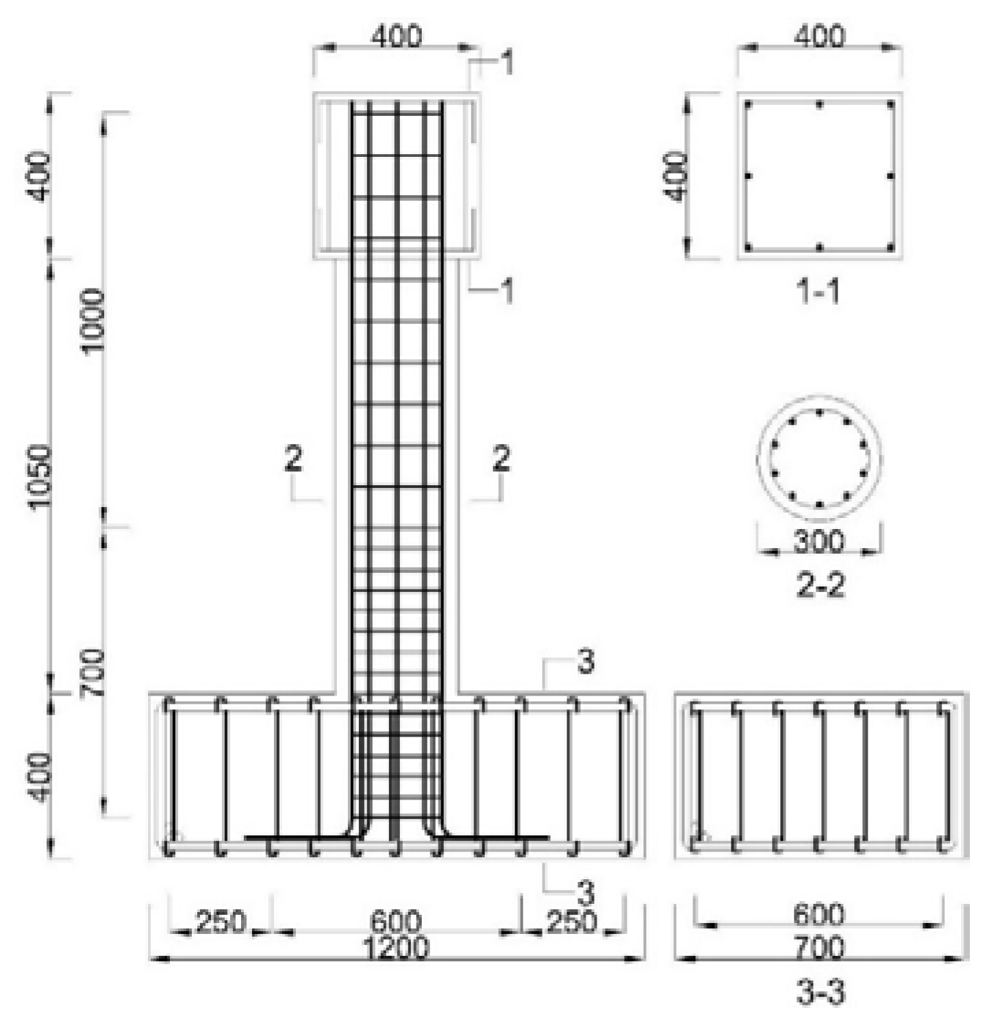
Figure 2.
Specimen pre-damage phenomena
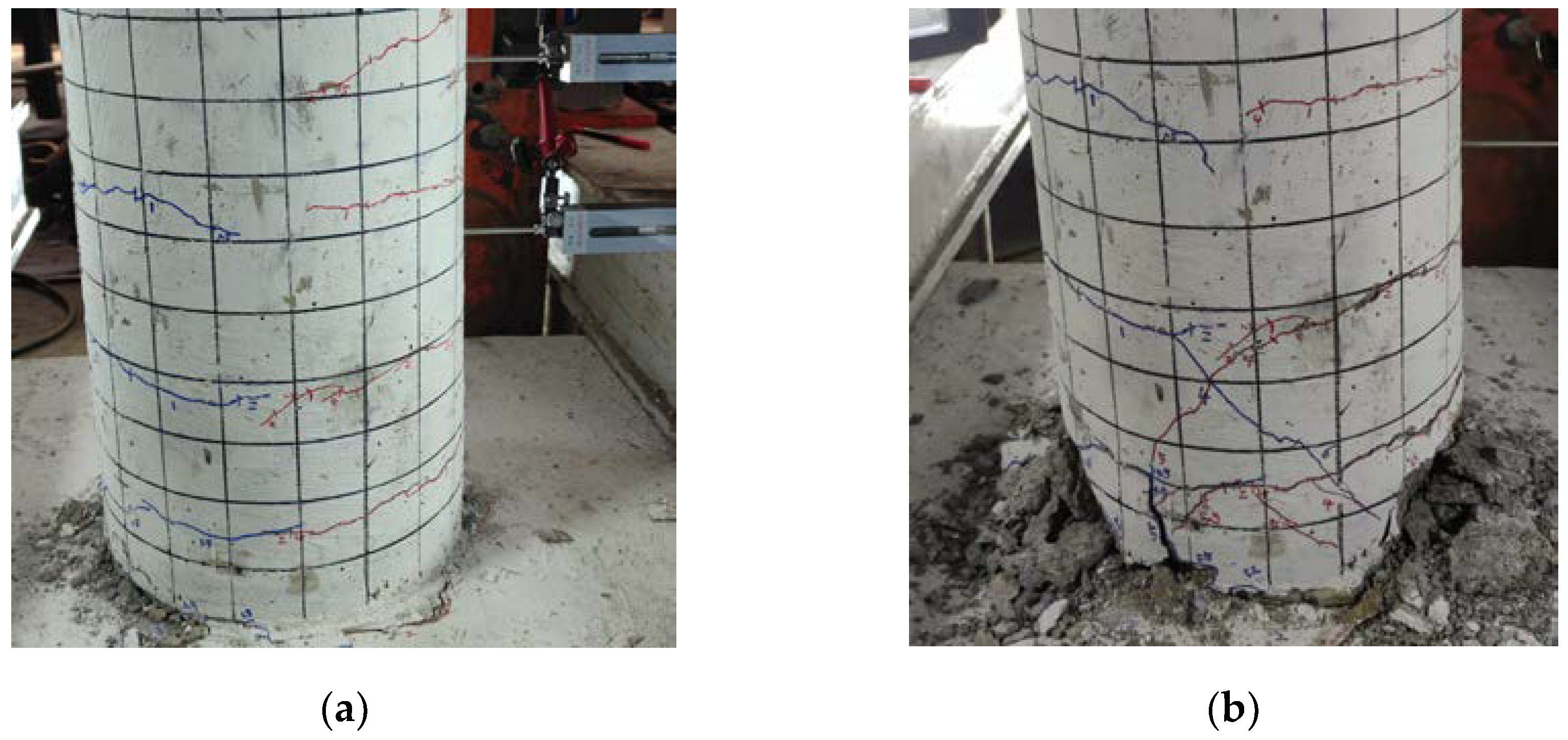
Figure 3.
Test loading device
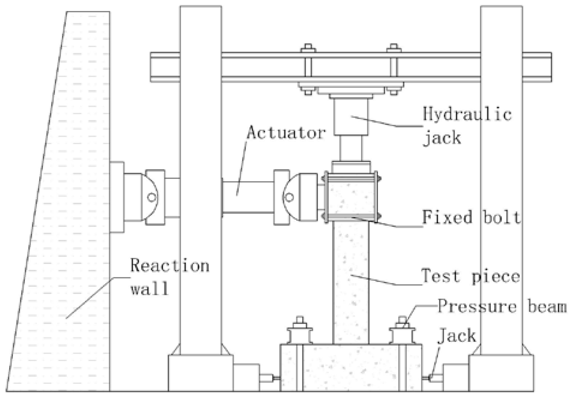
Figure 4.
Test loading system
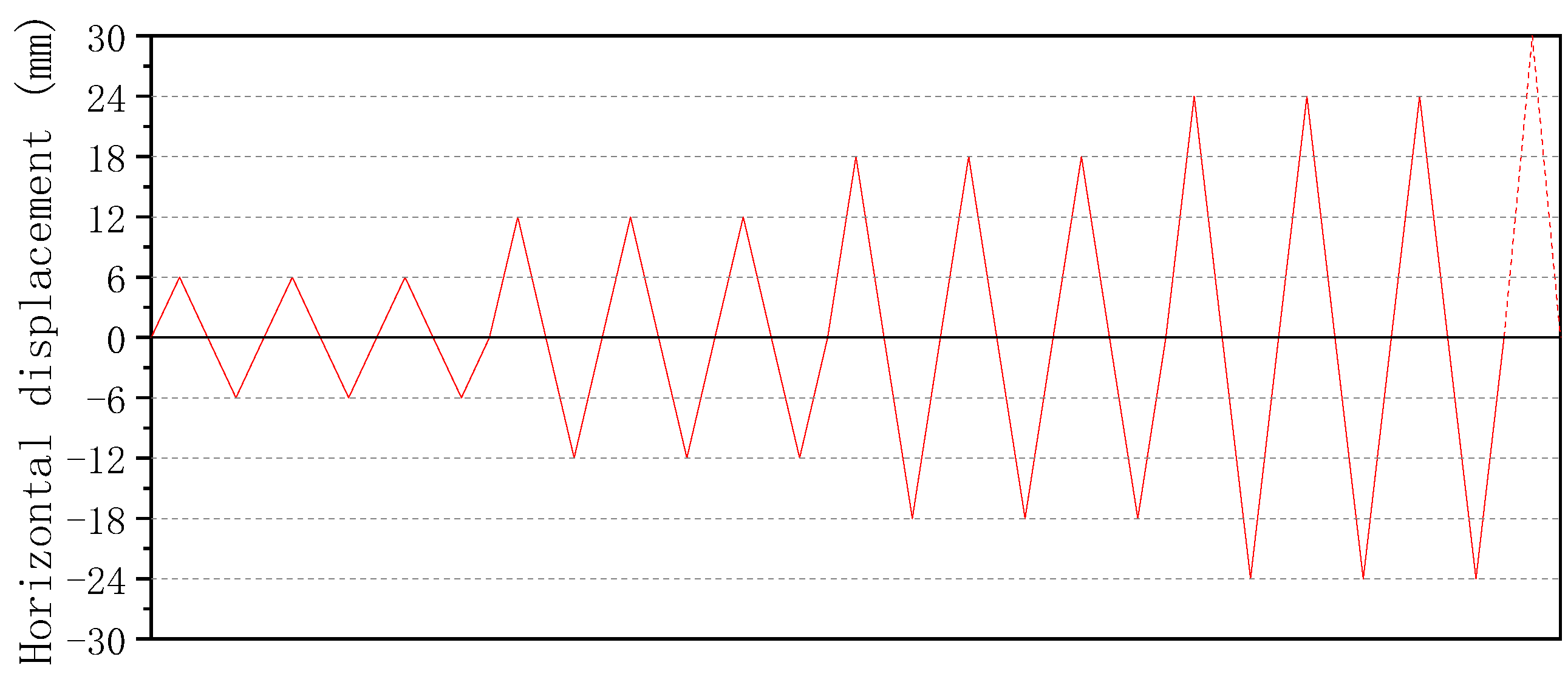
Figure 5.
Non-strengthened specimen test phenomena.
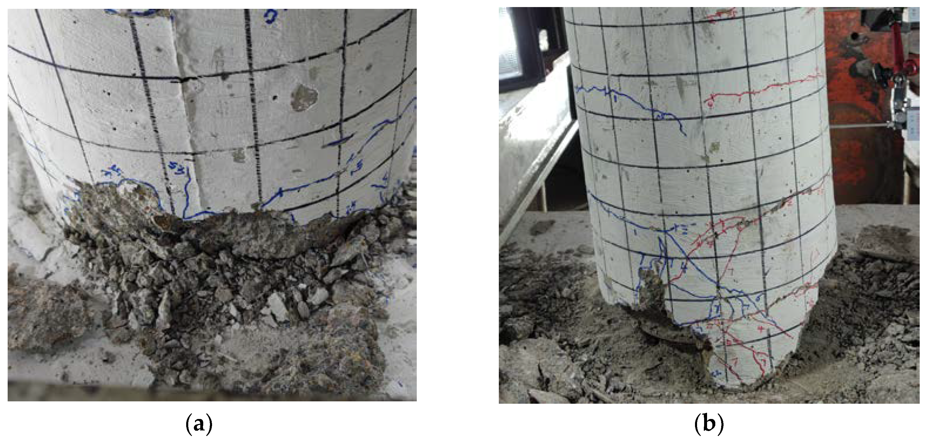
Figure 6.
Strengthened specimen test phenomena.
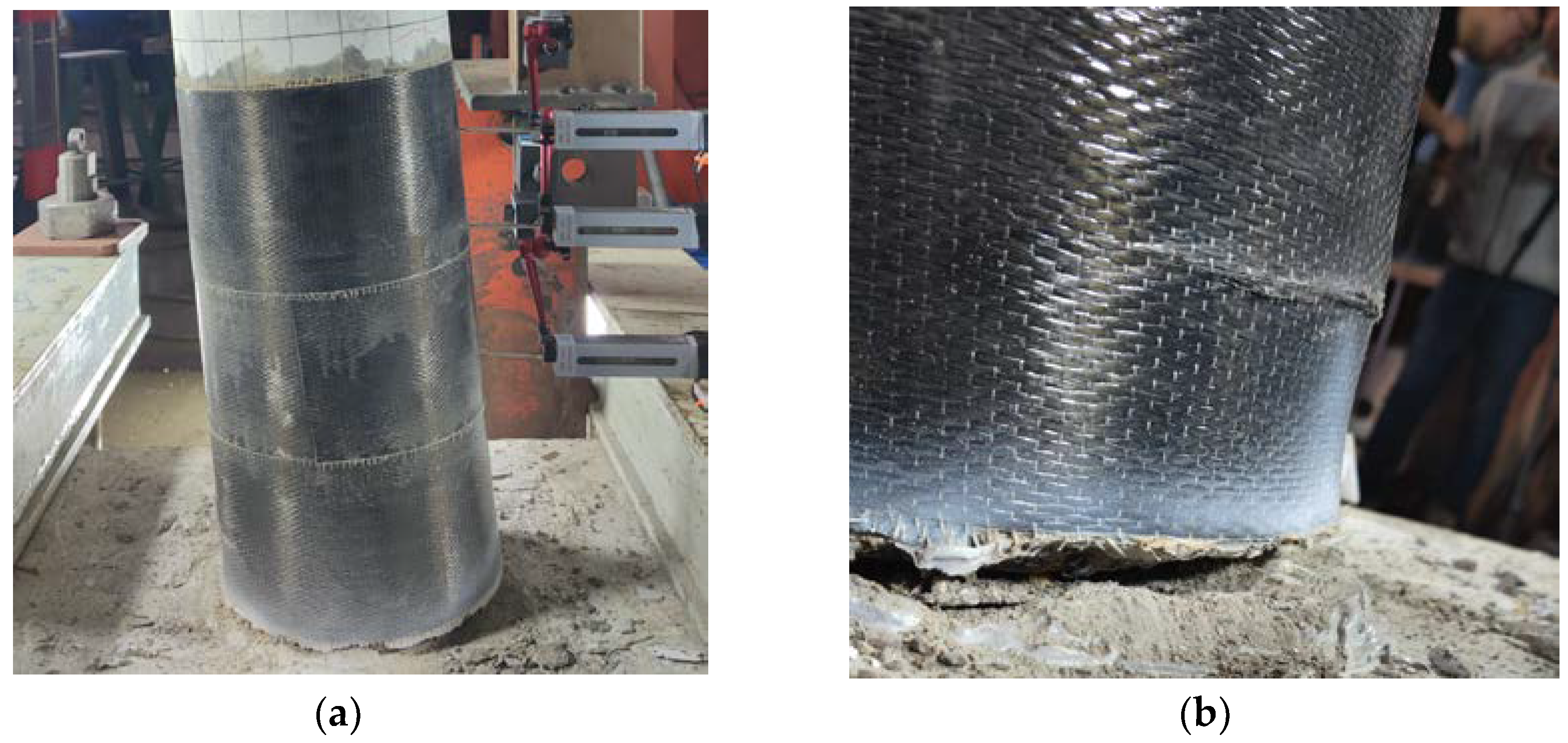
Figure 7.
Hysteretic curves of the specimens
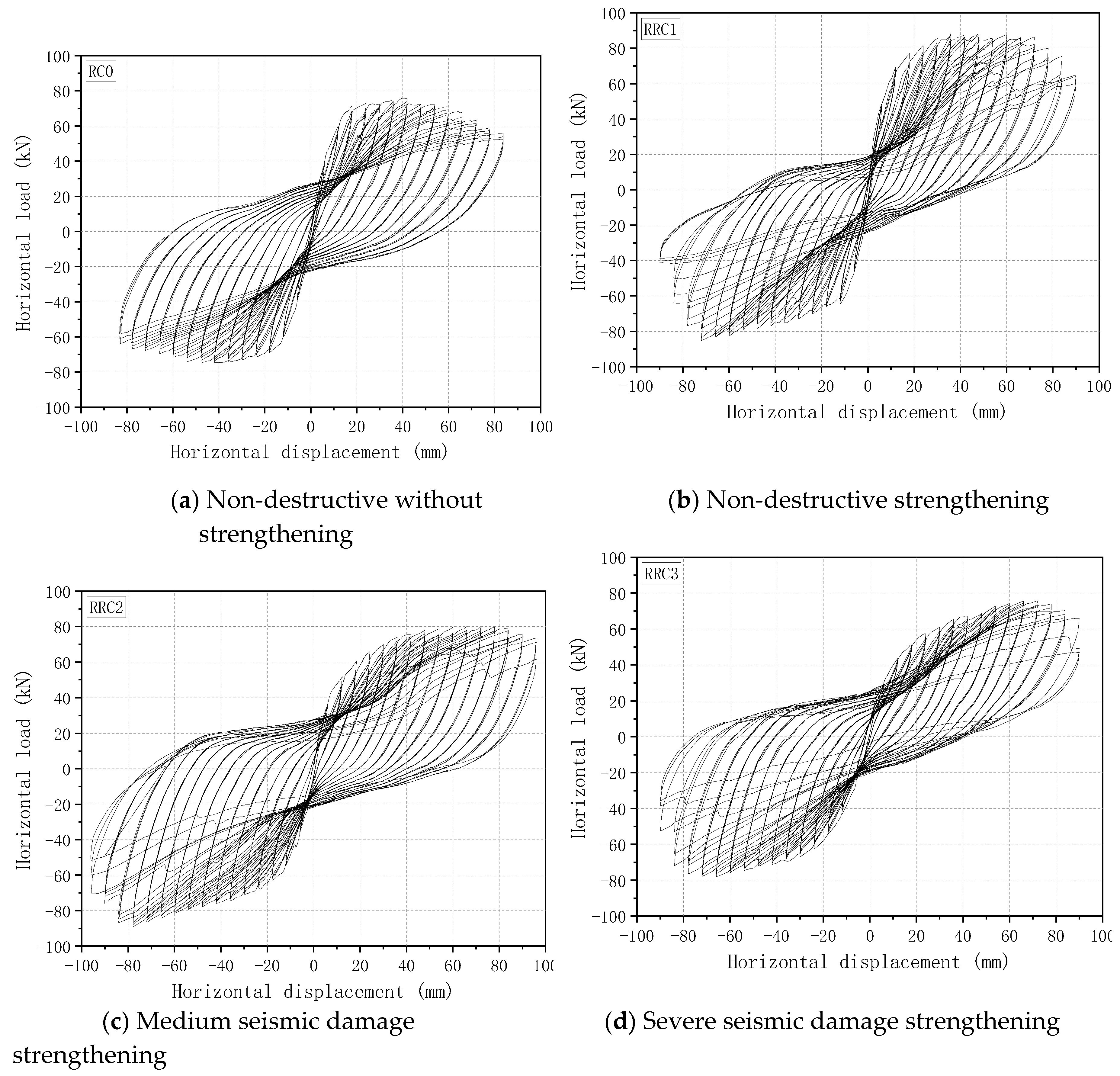
Figure 8.
Specimen skeleton curve comparison.
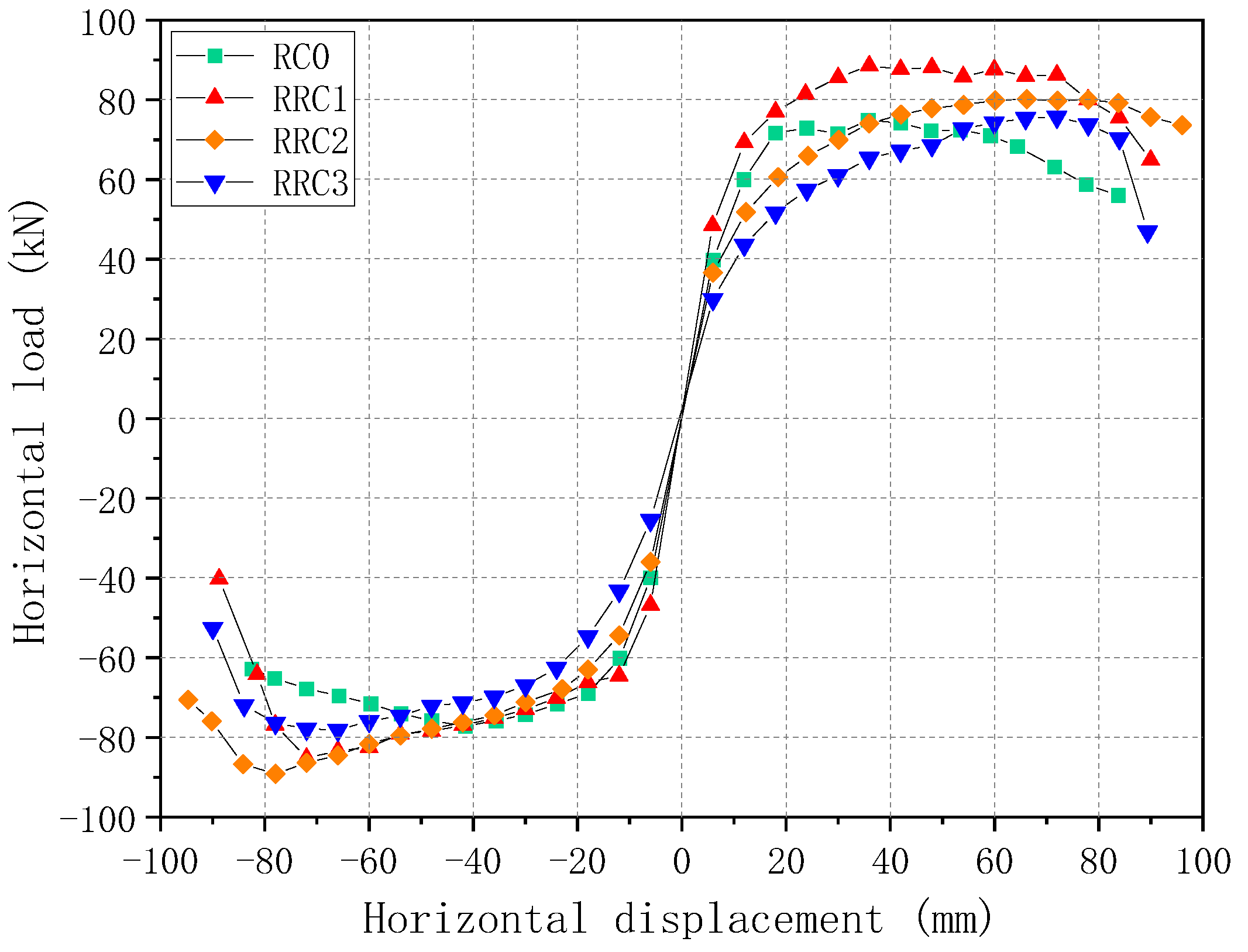
Figure 9.
"Farthest point" method.
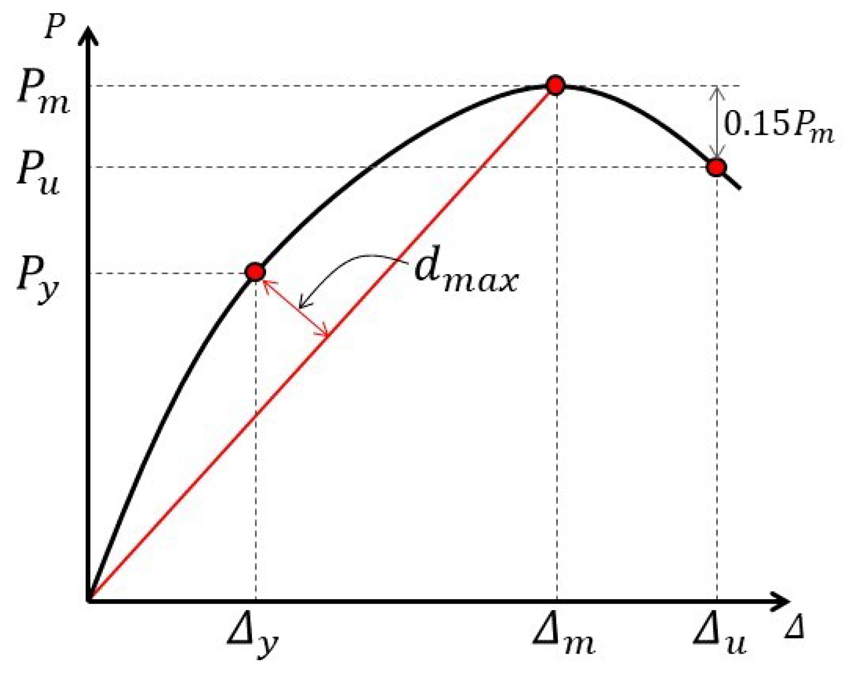
Figure 10.
Strength degradation curve comparison
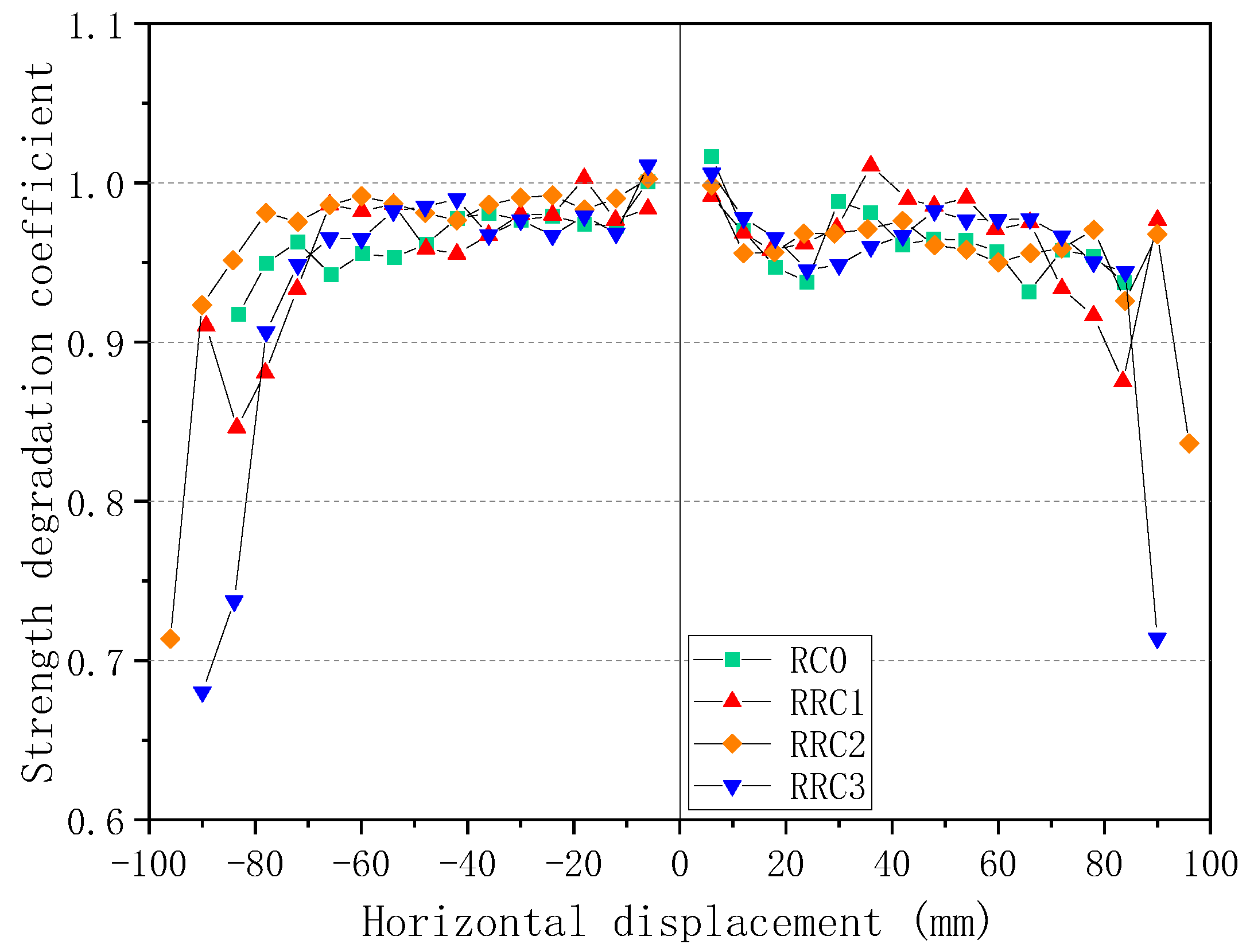
Figure 11.
Stiffness degradation curve comparison.
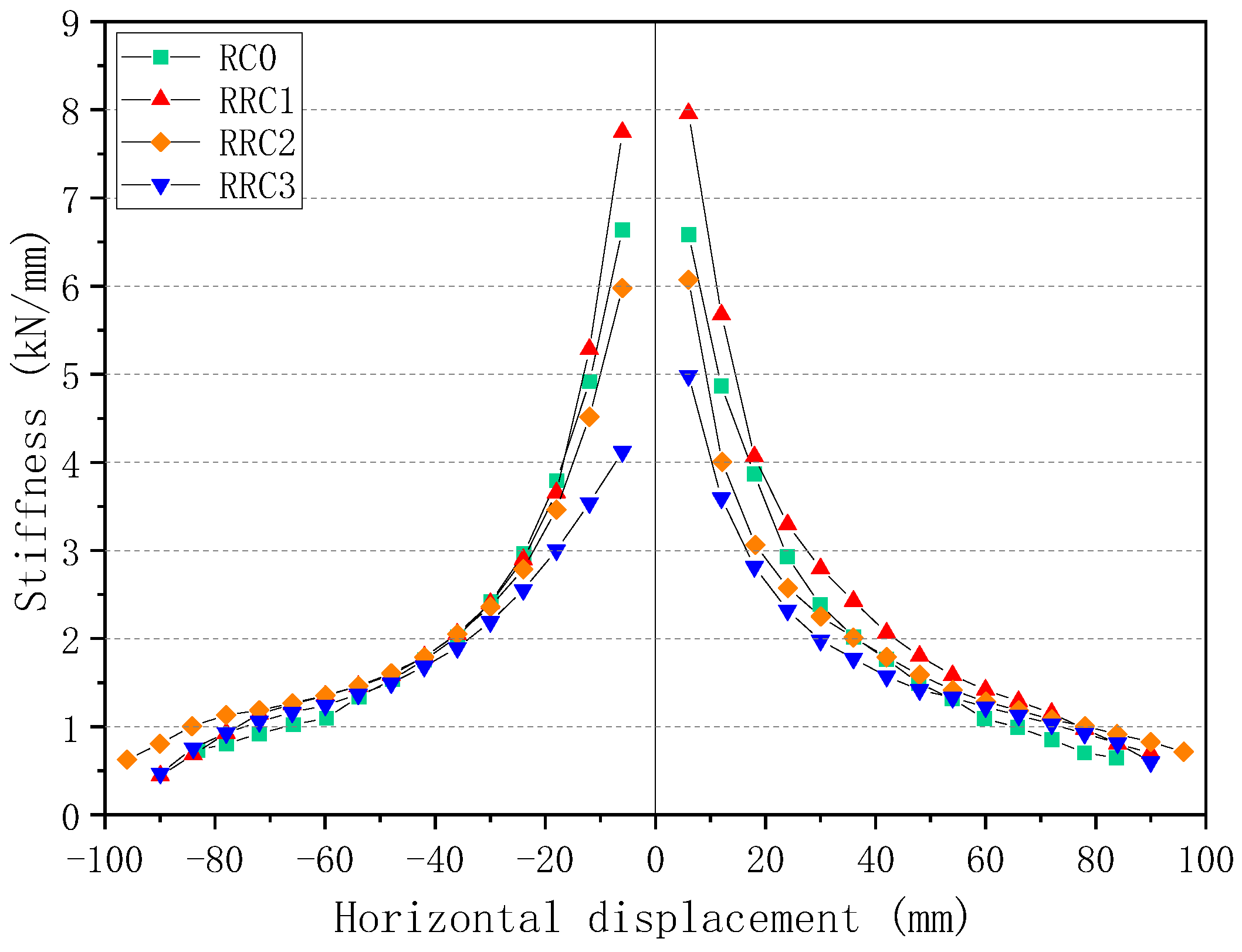
Figure 12.
Equivalent viscous damping coefficient comparison.
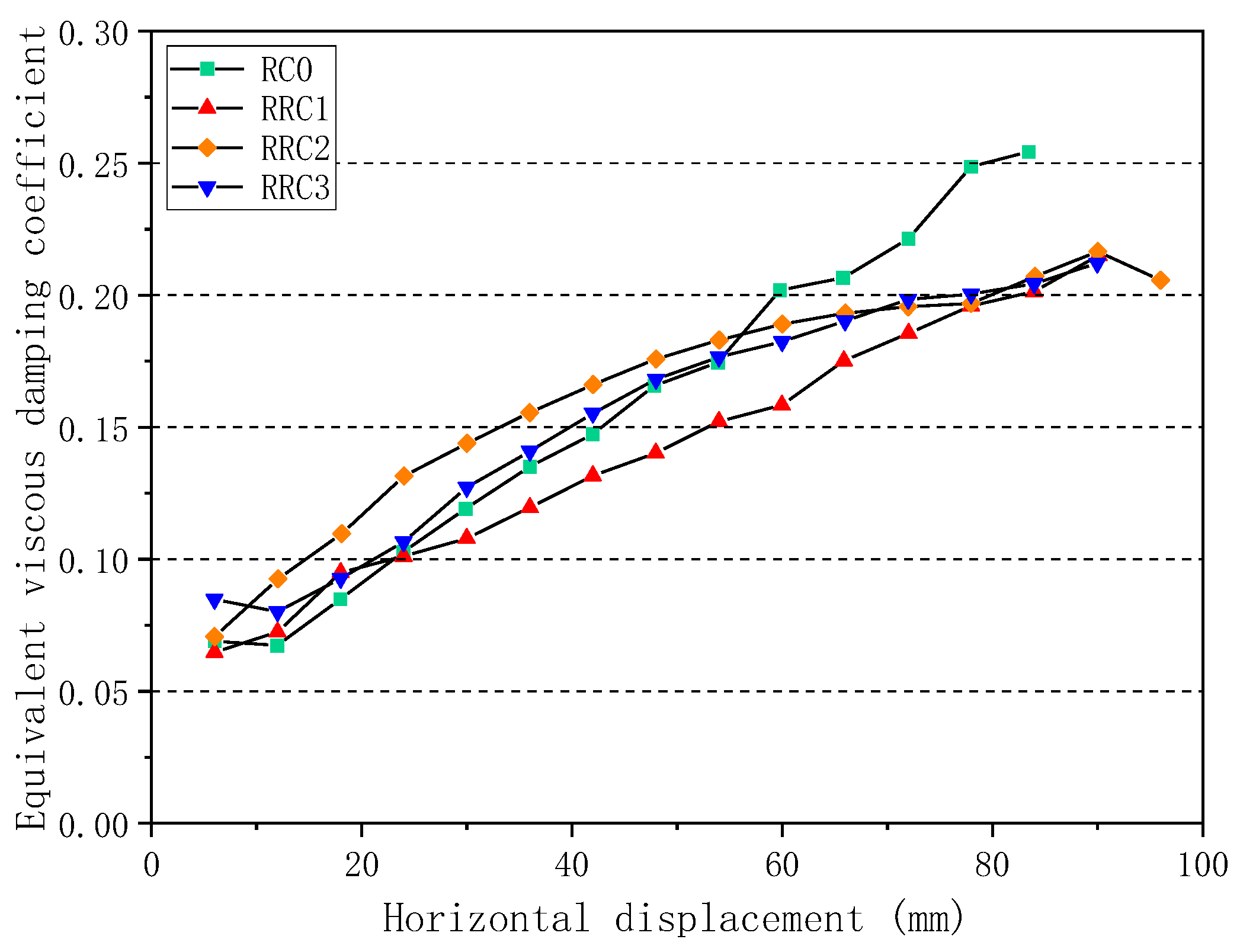
Figure 13.
Cumulative energy consumption change.
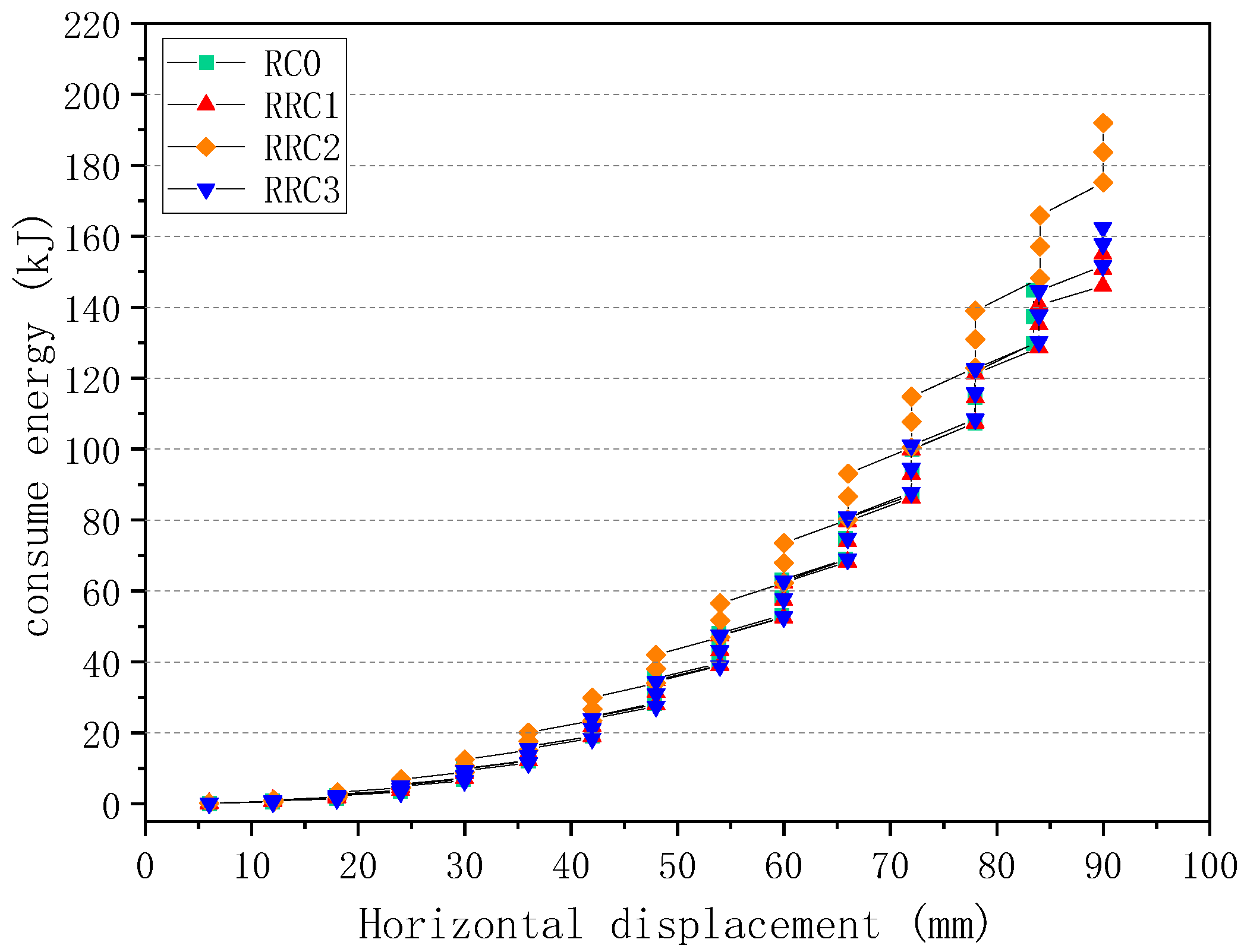
Figure 14.
Cumulative energy consumption comparison
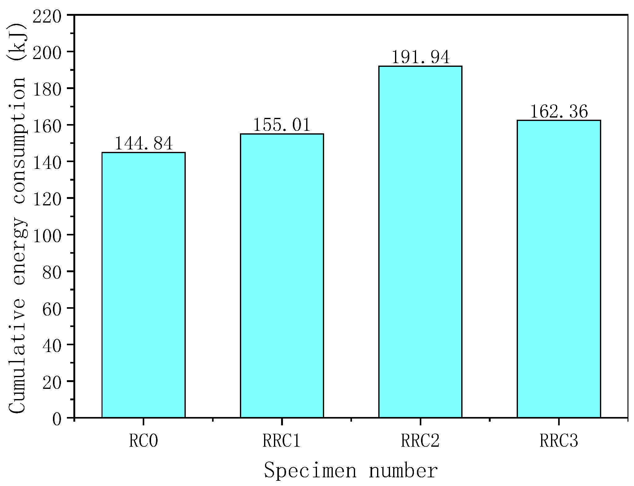

Table 1.
Design parameters of specimens.
| Specimen number |
Level of seismic damage |
Substitution rate |
Axial compression ratio |
Strengthening height level/cm |
Strengthening number of layers |
|---|---|---|---|---|---|
| RC0 | Non-destructive | 0% | 0.2 | -- | -- |
| RRC1 | Non-destructive | 50% | 0.2 | 60 | 3 |
| RRC2 | Medium seismic damage | 50% | 0.2 | 60 | 3 |
| RRC3 | Severe seismic damage | 50% | 0.2 | 60 | 3 |
Table 2.
Concrete material proportion
| Concrete number |
) | ||||||||
|---|---|---|---|---|---|---|---|---|---|
| Cement | Breeze | Fly ash | Mechanized sand | Recycled aggregate |
Natural aggregate |
water reducing agent | water | ||
| CL0 | 275 | 81 | 44 | 771 | 0 | 1000 | 16 | 175 | |
| CL50 | 275 | 50% | 44 | 771 | 500 | 500 | 16 | 194 | |
Table 3.
Concrete performance parameters
| Concrete number | Cubic compressive strength /MPa |
Prism compressive strength /MPa |
Splitting tensile strength /MPa |
Modulus of elasticity /MPa |
|---|---|---|---|---|
| CL0 | 49.2 | 42.5 | 3.92 | 34368.2 |
| CL50 | 46.8 | 39.4 | 3.56 | 32980.8 |
Table 4.
Reinforcing steel performance parameters
| Reinforcement number |
Diameter /mm |
Yield strength /MPa |
Ultimate strength /MPa |
Modulus of elasticity /MPa |
|---|---|---|---|---|
| HRB400 | 8 | 324.2 | 398.7 | 2. 10× |
| HRB400 | 12 | 432.5 | 510.4 | 2. 08× |
Table 5.
Performance parameters of CFRP, impregnating adhesive and repair adhesive
| Material | Tensile strength /MPa |
Compressive strength /MPa | Elastic modulus /MPa |
Calculated thickness /mm |
Extensibility |
|---|---|---|---|---|---|
| CFRP | 3950 | -- | 2.40× | 0.15 | 1.7% |
| Impregnating glue | 52.5 | 86.2 | 2711.7 | -- | 2.5% |
| Repair glue | 32.2 | 56.9 | 1962.8 | -- | -- |
Table 6.
Specimen pre-damage parameters.
| Specimen number |
Level of seismic damage |
Seismic damage status determination basis | Pre-damage loading displacement /mm |
|---|---|---|---|
| RC0 | Non-destructive | -- | -- |
| RRC1 | Non-destructive | -- | -- |
| RRC2 | Medium seismic damage | The crack width is 1~2mm, and the concrete begins to peel off. | 36 |
| RRC3 | Severe seismic damage | A large number of concrete peeled off, steel bars were exposed, and the horizontal bearing capacity reached the peak and then entered the descending section. | 54 |
Table 7.
Skeleton curve analysis table
| Specimen number |
Direction | Yield point | Peak point | Limit point | |||
|---|---|---|---|---|---|---|---|
| RC0 | + | 60.20 | 12.02 | 74.91 | 35.76 | 63.8 | 70.80 |
| - | 60.18 | 11.92 | 77.16 | 41.96 | 65.59 | 76.69 | |
| RRC1 | + | 69.16 | 11.95 | 88.55 | 35.99 | 75.27 | 84.07 |
| - | 64.58 | 12.10 | 85.18 | 71.97 | 72.40 | 79.20 | |
| RRC2 | + | 60.61 | 18.53 | 80.15 | 66.18 | 73.61 | 95.96 |
| - | 63.05 | 18.09 | 89.17 | 77.97 | 75.79 | 90.31 | |
| RRC3 | + | 51.83 | 18.14 | 75.72 | 71.98 | 64.36 | 85.34 |
| - | 62.60 | 24.02 | 78.16 | 65.98 | 66.44 | 85.67 | |
Table 8.
Displacement ductility factors
| Specimen number | Direction | ||
|---|---|---|---|
| RC0 | + | 5.893 | 6.164 |
| - | 6.435 | ||
| RRC1 | + | 7.037 | 6.794 |
| - | 6.550 | ||
| RRC2 | + | 5.179 | 5.086 |
| - | 4.992 | ||
| RRC3 | + | 4.705 | 4.136 |
| - | 3.567 |
Disclaimer/Publisher’s Note: The statements, opinions and data contained in all publications are solely those of the individual author(s) and contributor(s) and not of MDPI and/or the editor(s). MDPI and/or the editor(s) disclaim responsibility for any injury to people or property resulting from any ideas, methods, instructions or products referred to in the content. |
© 2023 by the authors. Licensee MDPI, Basel, Switzerland. This article is an open access article distributed under the terms and conditions of the Creative Commons Attribution (CC BY) license (https://creativecommons.org/licenses/by/4.0/).
Copyright: This open access article is published under a Creative Commons CC BY 4.0 license, which permit the free download, distribution, and reuse, provided that the author and preprint are cited in any reuse.


