Submitted:
23 April 2026
Posted:
27 April 2026
You are already at the latest version
Abstract
Grey cast iron brake discs remain standard in automotive braking systems due to their favorable thermal conductivity and mechanical strength. However, increasingly stringent environmental regulations, including Euro 7, necessitate enhanced surface durability to reduce particulate emissions and mitigate corrosion‑related degradation. In this context, Laser Metal Deposition (LMD) offers a promising route to engineer wear‑resistant coating systems with tailored microstructures. This study investigates phase formation and microstructural evolution in a 316L/430L‑WC multilayer coating deposited on grey cast iron (GJL) brake discs and subjected to brake‑shock testing to replicate thermomechanical load cycles representative of real braking conditions. X‑ray diffraction (XRD) performed on the interlayer region between the 316L and 430L‑WC layers revealed clear evidence of σ‑phase formation, indicating intermetallic transformations facilitated by thermal cycling. Microstructural characterization using scanning electron microscopy (SEM) and energy‑dispersive spectroscopy (EDS) identified localized enrichment of Cr‑ and Fe‑rich regions that support the XRD‑based interpretation of σ‑phase development. These results provide insights into phase transformations and elemental diffusion in LMD‑fabricated brake‑disc coatings. The findings advance the understanding of thermally induced transformations in multilayer steel systems and support the optimization of LMD coatings for high‑temperature and wear‑intensive applications through advanced analytical evaluation.
Keywords:
Laser Metal Deposition
; sigma phase
; XRD analysis
; WC reinforcement
; stainless steel 316L
; stainless steel 430L
; coating
; grey cast iron
; brake disc
1. Introduction
Grey cast iron (GJL) remains the dominant material for automotive brake discs due to its excellent thermal conductivity, vibration-damping capacity, mechanical strength, and cost-effectiveness, which together ensure stable braking, low noise, and robust performance under demanding duty [1,2].
Tribological investigations [3] and design-oriented analyses likewise emphasize that, although cast-iron brake discs are mechanically reliable, they remain susceptible to thermo-mechanical fatigue, vibration-induced instabilities, and friction-driven wear—factors that have become increasingly critical with modern vehicle performance and durability requirements [4,5,6].
Reducing non-exhaust particulate emissions from braking has therefore become a central regulatory and public-health objective [7]. Euro 7 introduces the first binding particle-emission limits for brake and tire wear and establishes standardized procedures for quantifying brake-particle emissions [8]. Multiple reviews show that, as tailpipe particulate emissions decline, non-exhaust PM—especially brake wear particles—has become a dominant contributor to urban PM burdens, motivating targeted material and system-level mitigation strategies [9].
Recent studies have demonstrated that particulate-matter emissions can be significantly reduced by increasing the wear resistance of friction surfaces, either through thermal treatments or through engineered coating systems that minimize abrasion at the pad–disc interface. Surface coatings are particularly effective because they interrupt the primary wear mechanisms that generate airborne particles, thereby lowering emissions both directly—by reducing disc material loss—and indirectly—by stabilizing frictional behavior and suppressing tribo-oxidation. The coating systems explored in the literature range from ceramic and composite materials to advanced metallic formulations and commonly serve as protective layers against abrasion, corrosion, and high-temperature degradation [10].
To achieve practical service performance, numerous deposition technologies have been evaluated—including PVD, CVD, and multiple thermal-spray processes—each capable of producing high-hardness, thermally stable coatings suitable for brake-disc environments [11]. Driven by Euro 7, the automotive industry is therefore moving toward next-generation protective coatings for grey cast iron discs to reduce particulate emissions while maintaining braking performance [12].
Laser Metal Deposition (LMD) has emerged as a highly effective approach for producing metallurgically bonded, wear- and corrosion-resistant coatings on GJL brake discs. LMD enables thin, uniform layers with strong adhesion, controlled heat input, and excellent manufacturability in both conventional and high-speed industrial implementations, making it compatible with Euro-7 requirements [13]. In contrast to galvanic or thermal-spray processes, LMD provides architectural flexibility for multilayer systems— such as stainless-steel transition layers serving as a first layer, combined with carbide-reinforced functional top layers as the second laye —that can be tailored for friction, durability, and load-specific thermal stability [14].
Two-layer multilayer architectures have already demonstrated enhanced wear resistance, improved microstructural stability, and reduced crack formation under simulated braking conditions [15]. Prior studies involving 316L-based multilayers and carbide-reinforced second layers have shown how microstructure and mechanical response evolve under thermomechanical loads representative of real braking, underscoring both the potential and the complexity of multilayer LMD systems applied to GJL [16].
However, combining austenitic (316L) and ferritic (430L) stainless steels within an LMD multilayer introduces the risk of thermally driven elemental diffusion and the formation of intermetallic phases in the interlayer region. Previous studies demonstrate that repeated thermal-mechanical cycling can significantly modify grain morphology, promote segregation, and trigger diffusion-controlled transformation reactions in LMD coatings [17].
In particular, material stacks containing 316L, 430L, and hard particles such as WC may experience phase transformations in the mixing zone during braking-like thermal cycling, potentially leading to σ-phase precipitation—an intermetallic phase known to embrittle stainless-steel-based systems and reduce corrosion resistance [13,18]. Kinetic and in-situ diffraction studies further indicate that σ-phase nucleation and growth occur within service-relevant temperature windows, reinforcing the importance of analyzing these transformations under realistic loading conditions [19]. Previous investigations on LMD-coated GJL systems have already documented microstructural evolution under braking, further motivating a detailed examination of interlayer phase development [15].
In this context, X-ray diffraction (XRD) provides critical insight [20]. XRD offers direct crystallographic identification of intermetallic phases—capabilities that SEM and EDS alone cannot reliably provide—making it essential for detecting σ-phase formation and linking it to thermal exposure and diffusion processes [17]. Consequently, XRD-supported microstructural analysis is indispensable for optimizing LMD-based multilayer coating architectures intended for Euro-7-compliant brake discs [21].
In multilayer systems combining austenitic 316L with ferritic 430L, the high chromium content and ferritic nature of 430L promote pronounced diffusion gradients during thermal cycling, creating Cr-enriched interlayer regions that are well-known nucleation sites for σ-phase in mixed α/γ microstructures [22]. Such Cr-rich ferritic domains accelerate σ-phase formation, especially between 600–900 °C, where σ-phase preferentially precipitates at α/γ interfaces and within δ-ferrite remnants [23]. Although fully austenitic 316L stainless steel exhibits only limited susceptibility to σ-phase formation, primarily due to its Ni-stabilized γ-matrix, the ferritic 430L layer introduces Cr-rich α-ferrite that substantially increases the thermodynamic driving force for σ-phase precipitation. Prior studies show that ferritic and duplex stainless steels develop σ-phase far more readily than austenitic grades, owing to the high Cr activity and δ-ferrite content in such systems [24]. Under thermal–mechanical cycling, interdiffusion between 430L and 316L enriches the interlayer region with chromium, facilitating eutectoid δ→σ+γ2 transformation and promoting σ-phase nucleation in the mixed α/γ microstructure, underscoring the need for detailed phase-evolution analysis in such multilayer systems [25]. Kinetic and in-situ diffraction studies confirm that these transformations occur within the thermal windows typical of braking events, reinforcing the relevance of characterizing σ-phase formation in 316L/430L LMD coatings [26].
The present study addresses this need by examining σ-phase formation, elemental redistribution, and microstructural evolution in a 316L/430L-WC multilayer LMD coating applied to grey cast iron and subjected to brake-shock testing.
2. Materials and Methods
This section summarizes the coating system, processing conditions, brake-shock testing procedure, and the experimental methods used for microstructural, chemical, and crystallographic characterization.
2.1. Substrate and Feedstock Materials
Grey cast iron brake disc with lamellar graphite, grade EN-GJL-150 was manufactured by (SHW Brake Systems GmbH, Tuttlingen, Germany), with outer diameter is precisely 365 millimeters and the thickness is specified in the following approximately 34 mm. Coating system (CS) was fabricated on full-scale grey cast iron brake discs. The coating thickness ranges between 250–300 µm. As illustrated in Figure 1, a three-dimensional representation is provided of the CS segment of the brake disc. A two-layer configuration CS was produced via laser metal deposition (LMD). The first layer consisted of austenitic stainless steel 316L powder, selected for its corrosion resistance and mechanical properties. The second layer consisted of ferritic stainless steel 430L reinforced with 30–40 wt.% spherical WC particles (5–40 µm), embedded within the 430L matrix.
Both steel powders (316L and 430L) were gas-atomized and supplied by Höganäs AB (Bruksgatan 34, 263 83 Höganäs, Skåne County, Sweden) with a certified particle-size distribution of 20–53 µm and ≤5% oversize/undersize. The nominal chemical compositions of all feedstock materials are provided in Table 1.
The coating system under investigation is illustrated in Table 2. All coatings were deposited on the entire surface of the brake disc utilizing an industrial LMD system that was outfitted with a coaxial powder nozzle and a continuous-wave fiber laser. The optimization of process parameters was conducted through a preliminary trial run, with considerations including laser power, scanning speed, powder feed rate, and shielding-gas flow. The objective was to ensure good metallurgical bonding and minimal degradation, thereby maximizing the efficacy of the process. The laser power utilized during deposition was approximately 10 kilowatts.
2.2. Brake Shock Corrosion Test/Thermo Mechanical Exposure
Following the coating process, the complete brake discs were tested for brake-shock corrosion in accordance with an automotive standard specification. A total of 1,200 brake cycles were executed over a period of approximately 36 hours, adhering to a predetermined sequence of braking and cooling intervals. The evaluation was conducted within a specialized industrial test apparatus that emulated authentic driving scenarios. The following components were included in the setup:
- ⮛
- The driving and braking simulation system can acquire temperature and rotational speed data.
- ⮛
- Corrosive salt-spray unit, providing intermittent salt exposure.
- ⮛
- Damp-heat chamber, applying cyclic humidity and elevated temperature.
- ⮛
- The disc was exposed to ambient conditions for 20 hours following the conclusion of the full sequence. This was designated as the storage step.
Due to the restrictions imposed by non-disclosure agreements, the technical drawings and force-measurement details cannot be made available. However, Figure 2 offers a high-level representation of the test’s workflow and environmental parameters.
2.3. Post-Processing and Sample Preparation
After completion of the brake-shock corrosion test, representative segments were taken from identical radial positions of the coated brake disc in cross-section and in top view sections. The samples were subsequently hot-mounted in acrylic resin (“Thermoplast”; ATM Qness GmbH, Emil-Reinert-Str. 2, 57636 Mammelzen, Germany). Metallographic preparation included sequential grinding and polishing to a final surface finish of 1 µm using diamond suspensions (ATM Qness GmbH). Final polishing was performed with an oxide polishing suspension (OPS) containing 0.25 µm alumina (Al2O3) slurry (Schmitz-Metallographie GmbH, Kaiserstraße 100, 52134 Herzogenrath, Germany).
To reveal microstructural features, the prepared cross-sections were etched using V2A etchant (ATM Qness GmbH) at 70 °C for 30 s. This procedure effectively delineated phase boundaries, carbide regions, and structural features within the multilayer coating.
For top-view investigations, the coating surface was progressively ground in a controlled manner until the intermixing zone between the 316L first layer and the 430L+WC second layer was exposed. This preparative approach ensured that subsequent analyses were conducted directly within the chemically and microstructurally modified interfacial region identified as transformation-susceptible. Final surface preparation was again performed using an oxide polishing suspension (OPS) with 0.25 µm alumina (Al2O3) slurry to obtain a flat, deformation-free surface suitable for high-resolution characterization.
2.4. Microstructural Characterization
Microstructural examinations were performed using optical microscopy (Zeiss Axioscope) and scanning electron microscopy (ZEISS EVO MA 15; Carl Zeiss Microscopy GmbH, Jena, Germany). Chemical analysis was conducted by energy-dispersive X-ray spectroscopy (EDS; Bruker Nano GmbH, Berlin, Germany) to characterize elemental distributions within the multilayer coating. Line scans, point analyses, and elemental maps were acquired to resolve Cr–Fe–Ni diffusion across the interlayer region separating the 316L first layer from the 430L+WC second layer. Particular focus was placed on the intermixing zone at the 316L/430L interface, where localized chromium enrichment was observed—an indicator commonly associated with conditions favorable for σ-phase nucleation.
2.5. X-Ray Diffraction (XRD)
To obtain phase-specific information from the multilayer coating after brake-shock exposure, X-ray diffraction (XRD) measurements were performed in a top-view configuration using Cu-Kα radiation. The analyzed surfaces were progressively ground and polished down to the intermixing zone between the 316L first layer and the 430L+WC second layer, as described in Section 2.3. This preparation ensured that the diffraction measurements probed the chemically and microstructurally modified interface region directly.
Top-view XRD scans recorded with Cu-Kα radiation were performed on the coating surface after controlled grinding until the intermixing zone between the 316L first layer and the 430L+WC second layer was exposed (see Section 2.3). This measurement configuration provides a reliable overview of the dominant crystalline phases present in the prepared interfacial region, including γ-Fe (austenite), α-Fe (ferrite), and WC, while offering high angular resolution and sufficient peak separation for robust phase.
Based on the scope of the present study, XRD evaluation was therefore restricted to Cu-Kα top-view measurements, and the crystallographic analysis presented in Section 3.4 is derived exclusively from this configuration.
2.5.1. Instrument & Geometry
X-ray diffraction measurements were carried out using a Bruker D8 DISCOVER diffractometer (Bruker AXS SE, Östliche Rheinbrückenstr. 49, 76187 Karlsruhe, Germany). The instrument was operated with a Cu-Kα radiation source (Kα1 = 1.5406 Å, Kα2 = 1.5444 Å). Diffraction patterns were collected over a scan range of 20–90° 2θ, employing a step size of 0.04° and a dwell time of 3 s per step.
This measurement geometry and wavelength selection provide reliable diffraction data for steel-based and carbide-reinforced coating systems, ensuring clear separation of the reflections associated with γ-Fe, α-Fe and WC. All XRD results discussed in the following section are based on this Cu-Kα configuration.
2.5.2. Measurement Locations
Diffraction measurements were performed within the intermixing zone between the 316L first layer and the 430L+WC second layer, which was exposed by controlled grinding and polishing of the coating surface (top-view configuration, see Section 2.3). This region was selected because its pronounced chemical gradients and multiphase character provide the highest sensitivity for detecting phase evolution induced by brake-shock thermomechanical loading.
Recording diffraction patterns from this location enabled reliable peak assignment and phase identification of the dominant crystalline constituents, including γ-Fe (austenite), α-Fe (ferrite), and WC. In addition, the crystallographic data allow assessment of phase stability and potential indications of intermetallic ordering in the diffusion-affected interface, which are discussed in Section 3.4.
2.5.3. Analysis Approach
Phase identification was carried out using COD and ICDD structural reference databases. Full-pattern Rietveld refinement was performed using HighScore Plus software (Malvern Panalytical), employing CIF-based structural models for γ-Fe (Fm-3m), α-Fe (Im-3m), and WC (P-6m2) as the primary crystalline phases of the multilayer coating. An additional σ-FeCr structural model (P42/mnm) was included for comparative evaluation, given the known susceptibility of Fe–Cr systems to σ-phase formation under thermomechanical loading.
The refinement procedure included zero-shift correction, lattice-parameter refinement, optimization of peak-shape parameters (U, V, W, η), and scale-factor adjustment to achieve reliable peak fitting and phase attribution. The inclusion of the σ-FeCr reference model allowed assessment of whether the experimental diffraction patterns exhibited any features consistent with intermetallic ordering, without implying definitive phase identification by XRD alone.
The Full-pattern Rietveld refinement was applied to extract lattice parameters, relative phase fractions, and peak-shape characteristics from the X-ray diffraction data, particularly suited for evaluating the multiphase steel–carbide coating system.
2.5.4. Sensitivity to σ-Phase
The selected scan range and analysis strategy using Cu-Kα radiation provide sufficient sensitivity for detecting crystallographic changes associated with phase evolution in Fe–Cr-based multilayer systems. While laboratory XRD with Cu-Kα radiation is primarily suited for identifying the dominant crystalline phases (γ-Fe, α-Fe, and WC), it can also reveal subtle deviations in peak shape, intensity, or background that may indicate the presence of additional ordering or transformation-related effects within diffusion-affected regions.
In Fe–Cr alloys, σ-phase formation is known to produce characteristic diffraction features that may partially overlap with reflections of γ-Fe or α-Fe. Under such conditions, full-pattern Rietveld refinement allows evaluation of whether the experimental diffraction data are consistent with the presence of intermetallic ordering, even when the expected phase fraction is low and close to the detection limit of laboratory XRD. Accordingly, a σ-FeCr structural model was included in the refinement as a comparative reference, without implying definitive phase identification.
It should be emphasized that, in the present work, XRD serves as a complementary technique to microstructural (optical/SEM) and compositional (EDS) analyses. Regions identified as transformation-susceptible by Cr-enrichment, Ni-depletion, and brittle, faceted morphology were therefore first localized by SEM/EDS, while XRD was used to assess whether these regions exhibit crystallographic features compatible with intermetallic phase evolution.
In the following sections, the thermomechanical loading conditions of the brake-shock test are presented (Figure 3), followed by correlation with microstructural observations (Section 3.2) and compositional gradients (Section 3.3). The XRD results (Section 3.4) are then discussed in this integrated context, focusing on phase stability and potential early-stage intermetallic ordering at the 316L/430L+WC interface.
2.6. Disclosure on the Use of Generative AI
No generative artificial intelligence (GenAI) tools were used for study design, data collection, analysis, or interpretation; minor language polishing may have been applied and does not affect scientific content.
2.7. Data Availability and Ethics
All data generated or analyzed during this study are available from the corresponding author upon reasonable request. No human or animal subjects were involved in this research, and therefore no ethical approval was required.
3. Results
The thermomechanical and chemical responses observed in this study reflect fundamental mechanisms also described in recent research on LMD-coated brake discs and Fe–Cr–based multilayer systems [15,16]. During braking, the disc is subjected to rapid temperature rises and steep thermal gradients, which can exceed several hundred degrees Celsius and induce plastic deformation, crack initiation, tribo-oxidation and microstructural evolution in grey cast iron and coated surfaces [27,28]. These effects are well documented for cast-iron and coated brake discs subjected to frictional heating and high thermomechanical stress, where repeated braking cycles lead to wear, thermal cracking, and oxidation-assisted degradation of the surface and subsurface microstructure [17]. Similar behavior has been reported for multilayer LMD coatings, where thermomechanical loading causes grain growth, microcrack formation and hardness reduction in both 316L and carbide-reinforced layers, demonstrating the sensitivity of such systems to braking-induced thermal cycling. Furthermore, recent studies on laser-based protective coatings for brake discs confirm that mechanical loading, transient heat flux, and diffusion-driven chemical gradients collectively influence phase stability and wear mechanisms under realistic service conditions [13]. Against this background, the following results illustrate how the applied brake-shock protocol affects the microstructure, elemental distribution, and phase constitution of the 316L/430L+WC multilayer coating.
3.1. Thermomechanical Loading Conditions
As shown in Figure 3, the brake simulation data was thoroughly reviewed and approved during the first 10-hour phase of the test procedure. This specific phase of the procedure marks the beginning of the brake-shock corrosion protocol, also known as the “brake disc driving and braking test.” During this phase, critical parameters such as speed profiles, braking intensity, and temperature dynamics are carefully documented. The test procedure included 1,200 braking operations, including 10 emergency braking cycles. These braking operations resulted in rapid deceleration from speeds of up to 180 km/h, leading to surface temperature peaks of approximately 650–750 °C.
The a.u. index thereby serves as a dimensionless indicator of braking severity; even low-intensity events result in measurable temperature increases, while values above ≈0.4 are typically associated with more pronounced thermal excursions and sharper temperature spikes.
Figure 3 illustrates this relationship by presenting, in the upper graph, the time dependent evolution of disc surface temperature in conjunction with the rotational speed profile. The lower graph correlates the same temperature data with the braking force index, highlighting how intensified braking events coincide with pronounced temperature spikes.
These results show that the brake-shock test imposes strongly fluctuating loading conditions, characterized by rapid heating during braking and cooling during subsequent acceleration, combined with corrosive and humid exposures in later stages of the test protocol [29]. The interaction of cyclic thermal expansion and contraction with friction-induced mechanical stresses forms the dominant driving force for the thermomechanical response of the multilayer coating [27,28]. Such coupled effects play a critical role in modifying local material behavior, promoting microstructural evolution, and influencing phase-transformation tendencies within the 316L/430L+WC system [15].
3.2. Microstructural Evolution After the Brake-Shock Corrosion Test
The combined optical microscopy and SEM investigations demonstrate that the multilayer coating undergoes pronounced thermomechanical modification during brake-shock exposure. The observed microstructural features diffusion-affected interlayers, crack network formation, and locally brittle, faceted regions—are consistent with degradation mechanisms reported for coated and uncoated brake discs subjected to severe thermal cycling, frictional heating, and mechanical loading [15,27]. Optical microscopy was first employed to obtain a large-area overview of damage-relevant features such as crack networks, etching contrast, and layer integrity, while subsequent SEM analysis enabled high-resolution characterization of localized interfacial regions and suspected transformation-affected microstructures. Together, these complementary techniques provide the microstructural basis for the chemical (Section 3.3, EDS) and crystallographic (Section 3.4, XRD) analyses discussed below.
3.2.1. Optical Overview Before and After Etching
Figure 4 presents panoramic optical micrographs of the top-layer surface after the brake-shock corrosion test. A pronounced network of surface cracks is clearly visible, providing direct evidence of severe thermal and mechanical loading during the brake-shock cycles. Such crack networks are characteristic of brake-disc materials exposed to repeated high-temperature gradients and friction-induced stresses and serve as a macroscopic indicator of load-induced damage accumulation.
At this stage, optical microscopy is intentionally applied as the first step of microstructural analysis, as it allows rapid inspection of large surface areas and reveals global damage patterns such as crack networks, surface degradation, and stress localization. This large-area overview is essential for identifying suspicious regions that may be susceptible to diffusion-controlled microstructural evolution or intermetallic transformation. Based on the optical inspection, representative zones can be selectively chosen for subsequent high-resolution SEM and EDS analysis, ensuring a targeted and efficient characterization workflow.
Figure 4 further compares the coated surface before etching (top row) and after V2A etching (bottom row), recorded from the same surface region. In the unetched condition, long, winding crack paths extend across the surface, consistent with macroscopic thermomechanical damage caused by repeated high-energy braking events and steep transient temperature gradients typical of brake-disc systems. Comparable crack morphologies have been widely reported for both uncoated grey cast iron and laser-coated brake discs subjected to cyclic frictional heating, thermal expansion and contraction, and tribo-oxidative loading [16,30].
After V2A etching, the 430L+WC second layer becomes clearly delineated, and localized variations in etching response appear along and adjacent to the crack morphologies. These regions reflect thermally and mechanically stressed microstructural zones that are influenced by diffusion-assisted processes and local chemical heterogeneity within the LMD multilayer system. Such etching-sensitive regions are commonly associated with thermally induced microstructural development in LMD coatings exposed to brake-like thermomechanical cycles and motivate the detailed SEM-based investigation of the intermixing zone presented in the following section [31].
Figure 5 shows optical micrographs of the cross-sectional microstructure of the 316L/430L+WC multilayer system after brake-shock exposure. The images clearly distinguish the WC-reinforced 430L second layer, the chemically graded intermixing zone, and the underlying 316L first layer. The second layer exhibits a dense population of nearly spherical WC particles embedded within the ferritic 430L matrix. Such morphologies are characteristic of LMD-processed carbide-reinforced coatings and are widely reported in laser-cladded brake-disc systems and multilayer stainless-steel composites [13].
The intermixing region between the first and second layers exhibits strong etching contrast, appearing as irregular, mottled, and banded zones. These regions are highlighted in Figure 5 by marked areas in the upper row and shown at higher magnification in the lower row. Similar diffusion-affected morphologies have been reported for LMD-fabricated multilayer coatings exposed to braking-related thermomechanical cycling, where repeated thermal excursions and mechanical shear promote local recrystallization, grain coarsening, and carbide–matrix interactions along Fe–Cr chemical gradients [16]. Finely etched, network-like patterns at the 316L/430L interface are commonly associated with diffusion-modified microstructures and may indicate early stages of intermetallic susceptibility in thermomechanically stressed Fe–Cr-based brake-disc materials.
3.2.2. SEM Interfacial Details Consistent with Diffusion-Affected Regions
Figure 6 presents SEM cross-sectional images of the same interfacial region identified by optical microscopy. The SEM images resolve individual spherical WC particles embedded in the 430L matrix and reveal a localized cavity-like zone within the intermixing region. At higher magnification, the cavity displays angular, faceted internal surfaces, which represent an objective morphological indicator of locally brittle behaviour.
Such faceted morphologies are frequently reported in chromium-enriched interface regions of LMD multilayers subjected to steep thermal gradients and mechanical shear, where diffusion-affected or intermetallic-susceptible microstructures may evolve. Subtle contrast variations around the cavity further indicate localized chemical heterogeneity, consistent with Fe–Cr–Ni diffusion processes known to be activated during repeated high-temperature braking events in Fe–Cr-based systems [32].
While SEM imaging alone cannot identify crystalline phases, the combination of faceted cavity morphology, chemical contrast variations, and localization within the intermixing zone is fully consistent with diffusion-affected interface regions reported for laser-processed multilayer brake-disc coatings under severe braking conditions braking [33]. The chemical and crystallographic nature of these regions is therefore examined in detail using EDS (Section 3.3) and XRD (Section 3.4).
3.3. EDS Results
Energy-dispersive X-ray spectroscopy (EDS) was carried out on the intermixing zone identified in Section 3.2, using three complementary acquisition modes: (i) point spectra on visually distinct sub-features, (ii) a line scan crossing the interface, and (iii) a 2D elemental map over the same field of view. The SEM micrographs guiding the analyses are shown together with the corresponding EDS overlays (magnification 10,000×; accelerating voltage 20 kV; working distance ≈ 9.2 mm).
3.3.1. Point Analysis
Figure 7 (EDS Point scan) marks six spots (“Spectrum (S) 1–6”) acquired inside the faceted cavity-like subregion and in adjacent matrix/ligament areas. The corresponding normalized mass concentrations (Cr, Fe, Ni, Mo; in wt.%) are summarized in Table 3. Only these four elements are reported because Cr, Fe, Ni and Mo represent the thermodynamically and crystallographically decisive constituents that control diffusion, chemical partitioning, and phase-transformation behavior in Fe–Cr–Ni–Mo systems. Chromium and iron form the primary backbone of both the 316L (austenitic) and 430L (ferritic) layers, while nickel stabilizes the austenitic regions and distinguishes Ni-bearing from Ni-free Fe-rich modes, molybdenum acts as a σ-phase stabilizer owing to its preferential occupation of specific sublattice sites in the tetragonal σ-structure. This element selection is supported by CALPHAD-based thermodynamic assessments, which show that σ-phase stability depends strongly on Cr enrichment, Ni depletion, and Mo-assisted sublattice stabilization in Fe–Cr alloys [34].
Furthermore, synchrotron Laue micro-diffraction studies on Fe–Cr alloys demonstrate that early σ-phase precipitation initiates at Cr-rich, Ni-poor interfacial zones, where elevated microstrain and steep diffusion gradients accelerate the α→σ transformation [35].
Therefore, restricting the EDS evaluation to Cr, Fe, Ni and Mo captures all chemically active elements that determine phase stability, diffusion pathways, and σ-phase susceptibility in the multilayer coating under brake-shock thermal cycling. Other alloying elements—present only in trace amounts—do not significantly influence σ-phase nucleation criteria or interfacial partitioning behavior and are thus excluded from Table 3.
The point-scan data in Figure 7 and Table 3 resolve three distinct compositional modes in the intermixing zone:
- spectra S1 and S2 capture a Cr-rich, Ni-depleted mode in the faceted interior (Cr ~41–46 wt%, Fe ~54–58 wt%, Ni ~0 wt%) [36]. These three modes are consistent with compositional partitioning reported for LMD-processed multilayers under brake-like thermal cycling, where interfacial chemistry segregates into Fe-rich ligaments and Cr-enriched interlayers.
- spectra S3 and S4 show an austenitic, Ni-bearing Fe-rich mode in surrounding ligaments (Fe ~75–77 wt%, Cr ~16–18 wt%, Ni ~5–6 wt%) [37]. The locally elevated Ni contents observed at selected points (≈ 5–6 wt.%) are insufficient to stabilize austenite at room temperature but represent a clear compositional signature of material derived from the austenitic 316L layer. Consequently, these regions are referred to as Ni-bearing compositional modes rather than as fully austenitic phases.
- spectra S5 and S6 represent a ferritic, Ni-free Fe-rich mode in adjacent ligaments (Fe ~82–83 wt%, Cr ~17–19 wt%, Ni ~0 wt%) [38].
The juxtaposition of the Cr-enriched interior (mode iii) with Fe-rich ligaments that are either Ni-bearing (mode i) or Ni-free (mode ii) demonstrates micro-scale Cr–Fe partitioning across the interface, a signature also observed in brake-loaded disc materials that develop interfacial gradients under steep, cyclic heat fluxes [39,40]. This chemical heterogeneity aligns with the etch-sensitive networks seen optically (Section 3.2) and indicates diffusion-affected interfacial chemistry under brake-shock thermal cycling in multilayer coatings.
While the Cr-rich/Ni-depleted chemistry of mode iii is compatible with σ-phase-prone compositions in Fe–Cr systems [35], EDS cannot establish crystal structure; definitive phase identification is therefore deferred to XRD/Rietveld (Section 3.4), in line with best practice for LMD coatings where defect formation and stress-assisted transformations require phase-resolved verification [41]. This protocol follows best practice: phase stability and interfacial site-preferences for σ in Fe–Cr are governed by thermodynamic/kinetic criteria that are treated within modern CALPHAD descriptions, and interfacial transformation pathways have been experimentally resolved via synchrotron Laue microdiffraction in Fe–Cr (α→σ) [35,42].
3.3.2. Line Scan Across the Interfacial Region
Figure 8 shows the EDS line scan across the first region described in Section 3.2, capturing the chemical gradient between the smoother ligament areas and the faceted, cavity like interior. The line scan was positioned deliberately to traverse this microstructurally distinct boundary to quantify the elemental variations across the interface.
The resulting intensity profiles exhibit a pronounced anti-correlation between Cr and Fe along the entire scan path. Within the central segment of the line scan, corresponding to the faceted interior of the cavity-like region identified in the SEM image (Figure 8), the Fe-Kα signal rises sharply and remains elevated over a broad distance, while the Cr-Kα signal decreases correspondingly and remains low throughout this region. Upon exiting the faceted zone, Fe intensity drops back toward its initial level, whereas Cr recovers to higher values. This Fe enriched / Cr depleted plateau within the cavity like region mirrors the compositional contrast identified in the point scan results (Figure 7), indicating a localized, diffusion modified subregion within the intermixing interface.
The Ni Kα and Mo Lα signals remain close to the baseline across the entire scan length, suggesting that both elements occur only in very low concentrations locally or fall below the EDS detection limit under the applied conditions. This behavior is consistent with the Fe–Cr dominated chemistry of the suspected transformation affected position.
3.3.3. EDS Mapping
Figure 9 presents the EDS elemental maps acquired at 10,000× magnification from the same transformation-suspected region examined in the point and line-scan analyses. The SEM reference image shows a distinct boundary between the faceted, cavity-like interior and the smoother surrounding ligament areas. The elemental maps visualize how this microstructural contrast corresponds to spatially heterogeneous chemical distributions.
The Cr map shows a diffuse but consistently higher signal in the ligament areas and at the periphery of the faceted region. In contrast, the Fe map reveals the inverse pattern, with a continuous Fe-enriched zone concentrated inside the faceted cavity. This spatial anti-correlation between Cr and Fe matches the trends observed in the point spectra (Figure 7) and the line profile (Figure 8), confirming that the faceted region represents a localized Fe-rich / Cr-depleted microregion, while the surrounding matrix retains a more Cr-rich composition.
The Ni and Mo maps display only isolated low-intensity spots and remain close to the baseline, consistent with their minor contributions in the point-scan (Table 3). Their limited spatial presence indicates that the transformation-suspected zone is overwhelmingly dominated by the Cr–Fe binary chemistry, which governs the diffusion behavior in this microstructurally altered region.
Overall, the EDS mapping demonstrates a coherent chemical partitioning pattern across the interface, with a Fe-rich faceted core surrounded by Cr-richer ligament material. Such chemical gradients are characteristic of diffusion-affected intermixing zones subjected to severe thermal cycling and complement the morphological observations discussed in Section 3.2.
3.4. X-Ray Diffraction (XRD) Results
X-ray diffraction (XRD) was employed to characterize the phase constitution, crystallographic structure, and lattice distortion of the investigated laser metal deposited (LMD) intermixing region after brake-shock testing. XRD provides detailed insight into both the phase assemblage and the stress-affected crystal structure of the multiphase system formed during processing and subsequent thermo-mechanical loading.
The diffraction patterns reveal the presence of the γ-Fe (austenite), α-Fe (ferrite), WC reinforcement, and the σ-FeCr phase. Owing to the complex tetragonal crystal structure of the σ-phase and the dense distribution of its diffraction peaks, σ-phase identification was not based on individual reflections but on characteristic reflection groups in defined 2θ regions where σ-phase reflections coexist with matrix and reinforcement phases. These reflection groups form a robust fingerprint for σ-phase identification in multiphase Fe-based systems.
Following phase identification and peak indexing, the diffraction data were further evaluated to extract crystallographic lattice parameters. This transition from reflection-based phase analysis to lattice parameter refinement enables a consistent description of the crystal structure, accounting not only for phase presence but also for lattice distortions induced by processing and testing.
The refined lattice parameters of the identified phases are listed in Table 4. The σ-phase lattice parameters refined in this study represent effective values reflecting the experimentally stressed state of the material after brake-shock testing. Consequently, these values are not expected to exactly match reference crystallographic information file (CIF) data obtained from idealized or stress-free structures reported in databases such as the Materials Project or the Crystallography Open Database (COD).
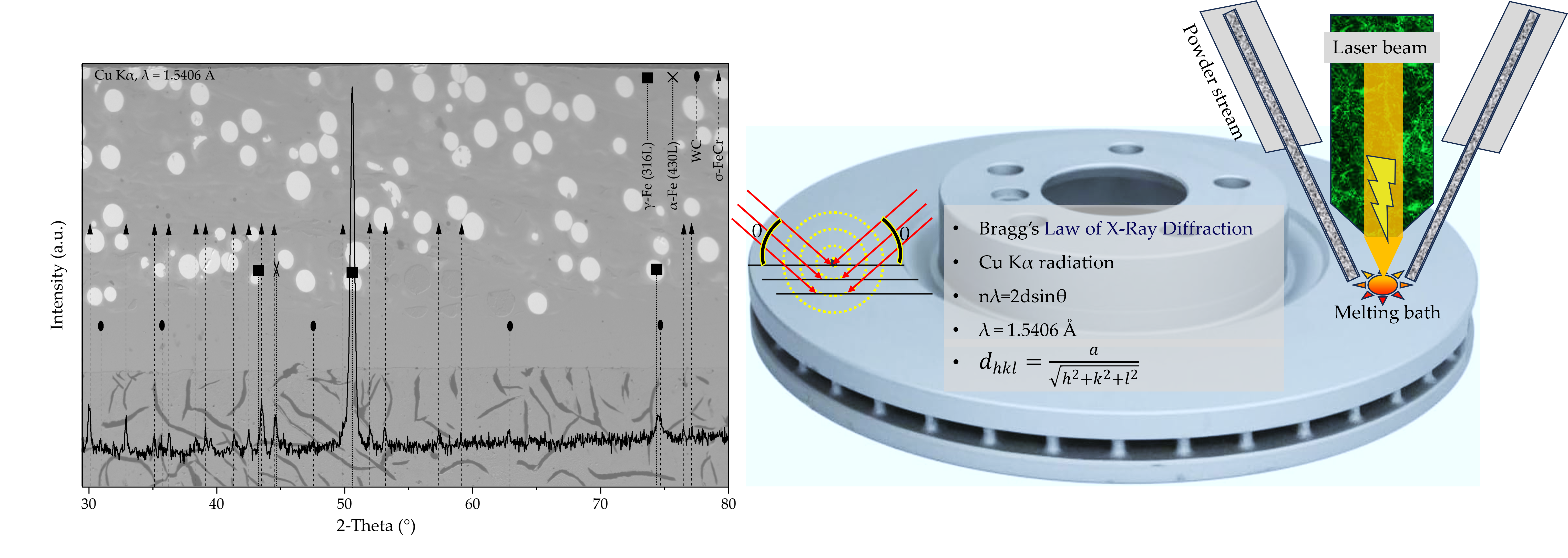
3.4.1. Phase Constitution and Lattice Characterization Based on Bragg’s Law
Figure 10 shows the XRD pattern of the LMD intermixing region, recorded using Cu Kα radiation (λ = 1.5406 Å). The diffractogram reveals a complex multiphase constitution consisting of γ-Fe (austenite, 316L), α-Fe (ferrite, 430L), hexagonal WC reinforcement, and a pronounced contribution of the tetragonal σ-phase (σ-FeCr). A detailed peak analysis including experimental interplanar spacings, crystallographic indexing, phase assignment, space-group information, and characteristic σ-phase reflection groups is summarized in Table 5.
The experimental interplanar spacings (dexp) were calculated from the measured diffraction angles using Bragg’s law Equation 1 [43].
where n is the diffraction order (n = 1), λ is the X-ray wavelength (Cu Kα, λ = 1.5406 Å), d is the interplanar spacing, and θ is the Bragg angle corresponding to half of the measured 2θ value.
For the tetragonal σ-phase (σ-FeCr, space group P42/mnm), the theoretical interplanar spacings (dtheor) were calculated using the lattice spacing Equation 2 from the crystallographic plane indices (h, k, l). The refined lattice parameters (a and c) are listed in Table 4. [44].
For cubic phases (γ-Fe and α-Fe), the interplanar spacing was calculated according to Equation 3, where a is the corresponding cubic lattice parameter.
For hexagonal WC, the Miller–Bravais notation (h k i l, with i = –(h + k)) was applied, and the interplanar spacing was calculated using Equation (4)
The comparison between experimentally determined interplanar spacings (dexp) and theoretically derived lattice spacings (dtheor) provides a basis for assessing lattice distortion and quantifying compressive residual lattice strain, particularly for σ-phase reflections.
3.4.1.1. Identification of Matrix and Reinforcement Phases
The γ-Fe phase is clearly identified by its characteristic fcc reflections at 2θ ≈ 43.52° (111), 50.69° (002), and 74.50° (022), which are well resolved in Figure 10 and consistently confirmed by Bragg’s law (Table 5). These peaks unambiguously confirm the presence of the austenitic 316L contribution within the intermixing region. Comparable γ-Fe peak positions and intensities have been reported in Fe-Cr-Ni systems containing secondary intermetallic phases [45,46].
Similarly, α-Fe originating from the 430L component is confirmed by its dominant bcc (011) reflection at 2θ ≈ 44.67°. The corresponding experimental and calculated d-spacings are in excellent agreement with theoretical values derived from the refined bcc lattice parameter reported in Table 4, indicating negligible lattice distortion for the ferritic phase.
The presence of WC particles is verified by a series of hexagonal reflections indexed using the Miller–Bravais [47] (h k i l) i=−(h+k) notation, including (001), (100), (011), (002) and (012). These reflections appear at the expected angular positions (e.g., ≈30.93°, 36.35°, 48.17°, 63.51°, and 74.82°) and are consistently confirmed by Bragg’s law, demonstrating the structural integrity of the WC reinforcement within the LMD matrix. These reflections appear at the expected angular positions and are consistent with previous reports on WC-reinforced Fe-based composites processed under rapid solidification conditions [48,49].
3.4.1.2. σ-. phase Identification Based on Characteristic Reflection Groups
In addition to the matrix and reinforcement phases, a significant fraction of diffraction peaks is attributed to the σ-phase (σ-FeCr), crystallizing in the tetragonal space group P42/mnm. Owing to the large and complex unit cell of the σ-phase, phase identification is based not on isolated diffraction peaks but on the presence of characteristic Reflection groups, i.e., groups of closely spaced reflections occurring in distinct 2θ regions.
Based on the peak distribution in Figure 10 and the systematic evaluation in Table 5, four characteristic σ-phase diffraction Reflection groups are identified:
- (≈ 30–39° 2θ): reflections such as (121), (221), and related planes, all confirmed by Bragg’s law.
- (≈ 41–45° 2θ): including reflections such as (040), (410) and (022), partly overlapping with γ-Fe (111) and α-Fe (011).
- (≈ 49–59° 2θ): dominated by σ reflections such as (222), (241), (050), and related planes.
- (≈ 75–80° 2θ): higher-index σ reflections including (143), (071), and related planes.
σ-phase characteristic diffraction peaks were identified, and the formation of the σ-phase was confirmed by comparison with ICDD reference patterns. Owing to pronounced peak overlap, Rietveld refinement was applied to ensure robust phase analysis. The simultaneous occurrence of reflections corresponding to all four characteristic σ-phase reflection groups provides strong evidence for σ-phase formation within the LMD intermixing region. This reflection-group-based identification approach is particularly robust for σ-FeCr phases, as the high density of crystallographically allowed reflections and frequent peak overlap render phase identification based on individual reflections unreliable.
The σ-phase identification was further supported by comparison with reference σ-phase crystal structures obtained from the Materials Project database (e.g., mp-1194030) [50,51]. Deviations in relative peak intensities between the calculated reference pattern and the experimental XRD data are attributed to residual stresses, compositional variations, phase overlap, and crystallographic texture inherent to the laser metal deposition process. This identification strategy is well established for σ-FeCr phases, where the high density of allowed reflections and frequent peak overlap make single-peak identification unreliable [52,53].
3.4.1.3. Apparent Compressive Lattice Strain of the σ-phase
The lattice strain associated with σ-related reflections was evaluated by comparing experimentally determined interplanar spacings () with theoretically derived reference spacings () obtained from the ideal tetragonal σ-FeCr lattice based on crystallographic plane indices (hkl) and database/CIF lattice parameters. The strain index for each reflection was calculated according to Equation 5 [57].
Negative values of indicate an apparent compressive lattice distortion relative to the theoretical lattice spacing. This Bragg-spacing-based formulation is a standard approach in X-ray diffraction analysis for assessing lattice distortions in metallic and intermetallic systems.
It should be emphasized that deviations between and cannot be attributed exclusively to residual stresses. In diffusion-affected, multiphase interlayers such as the present LMD-fabricated coating, the apparent lattice-strain index may also be influenced by deviations from ideal stoichiometry, local chemical ordering, diffraction-peak overlap with resulting peak-position bias, fitting and model uncertainties, instrumental effects (e.g., specimen displacement or zero-shift), crystallographic anisotropy, and load-sharing effects between coexisting phases. Consequently, the reported values are interpreted as apparent diffraction-based lattice strain indices rather than as unique residual-stress magnitudes.
σ-related reflections belonging to Reflection Groups I and IV exhibit negligible lattice distortion (), indicating interplanar spacings close to the theoretical values. In contrast, reflections associated with Reflection Group II show moderate apparent compressive distortion (approximately ), while Reflection Group III exhibits pronounced apparent compression, with values reaching up to approximately .
In the present system, the apparent compressive lattice strain distortion observed for σ-susceptible reflection groups is attributed to the cumulative thermo-mechanical history of the intermixing zone, including stresses introduced during rapid solidification in LMD processing and subsequent stress redistribution under cyclic brake-shock loading. The effect is further enhanced by strong mechanical constraint from the surrounding γ-Fe, α-Fe, and WC phases, as well as by the high density and partial overlap of σ-related reflections within the 49–59° 2θ range, which can bias effective peak positions used for strain estimation [53,58,59]. Similar observations of compressive strain localization and reflection-dependent lattice distortion have also been reported in detailed crystallographic and diffraction-based investigations [60,61].
4. Discussion
The brake-shock corrosion test subjects the multilayer coating to severe and cyclic thermomechanical loading, combining rapid temperature fluctuations, high mechanical shear stresses, and corrosive exposure. As demonstrated in Section 3.1, braking events generate pronounced temperature peaks, leading to repeated heating and cooling cycles in the surface and near-surface regions of the coating. Such service-like loading conditions are well known to promote interdiffusion, elemental redistribution, and microstructural instability in Fe–Cr-based alloys, particularly at interfaces between austenitic and ferritic phases.
The intermixing zone between the 316L first layer and the 430L+WC second layer represents a chemically and mechanically heterogeneous region. Differences in thermal expansion coefficient, elastic modulus, and thermal conductivity between the two layers induce additional local stresses during brake-shock loading, thereby accelerating diffusion-assisted microstructural evolution. Consequently, the observations reported in this study reflect the combined influence of thermal cycling and mechanical loading rather than purely thermally driven aging phenomena.
X-ray diffraction provides insight into the overall phase constitution and the stress-affected crystallographic state of the laser metal deposited (LMD) intermixing region after brake-shock testing, highlighting the strong coupling between processing conditions, service-like loading, and subsequent microstructural evolution [59].
The coexistence of the dominant matrix phases γ-Fe, α-Fe, and WC, together with diffraction features compatible with σ-FeCr intermetallic ordering, reflects the complex non-equilibrium microstructure produced by rapid solidification during LMD processing and subsequently modified by cyclic thermomechanical loading during brake-shock exposure [55].
4.1. Microstructural Signatures of Transformation-Susceptible Regions
Optical microscopy and SEM reveal the emergence of a faceted, cavity-like microstructural feature localized within the intermixing zone after brake-shock exposure. The sharp, angular, brittle-appearing morphology contrasts with the smoother ligament areas of the surrounding matrix and is characteristic of locally hardened or transformation-affected microdomains formed under thermomechanical loading.
Although faceted morphology alone does not constitute proof of σ-phase formation, its confinement to the interface and pronounced geometric contrast strongly suggest a distinct interfacial evolution pathway. This localization supports the interpretation that the intermixing zone is the most transformation-susceptible region of the multilayer coating under brake-shock conditions [62].
Such localized transformations may affect crack initiation, wear behavior, and corrosion resistance under extended braking duty cycles, emphasizing the need for careful control of interfacial chemistry and dilution during LMD processing, for example through optimized transition layers or reduced thermal gradients [62].
4.2. Chemical Phase Separation and Diffusion-Controlled Interfacial Chemistry
EDS point, line, and mapping analyses demonstrate localized chemical partitioning within the transformation-suspected region. Three compositional modes—Ni-bearing Fe-rich, Ni-free Fe-rich, and Fe-enriched/Cr-depleted—indicate a chemically heterogeneous interface formed by diffusion-controlled redistribution under service-like thermomechanical loading [17].
The consistent Cr–Fe anti-correlation observed across EDS datasets shows an Fe-enriched, Cr-depleted core region surrounded by comparatively Cr-richer ligaments. The negligible spatial contribution of Ni and Mo confirms that the interfacial chemistry is overwhelmingly governed by the Fe–Cr binary system, which controls diffusion behavior and transformation susceptibility in such alloys [34,35].
Such Cr–Fe partitioning is a prerequisite for intermetallic phase instability in Fe–Cr systems and is widely recognized as a critical chemical condition for σ-phase susceptibility, even though EDS itself cannot resolve crystallography [63].
4.3. XRD and Diffraction-Based Assessment of Intermetallic Contributions
X-ray diffraction performed in a Cu-Kα top-view configuration confirms the presence of the dominant crystalline phases γ-Fe, α-Fe, and WC within the multilayer coating after brake-shock exposure, indicating that the primary phase architecture remains intact at the macroscopic scale [10].
Laboratory XRD does not provide unambiguous crystallographic evidence for σ-phase formation. This is consistent with the highly localized nature and expected low volume fraction of the transformation-affected region, which likely lies at or below the detection limit of Cu-Kα XRD. Full-pattern Rietveld refinement can assess compatibility with intermetallic ordering; however, such results must be interpreted cautiously and in conjunction with microstructural and compositional evidence [35,64].
Accordingly, XRD serves as a supporting technique, complementing SEM and EDS rather than acting as a standalone method for σ-phase identification in diffusion-affected interfaces.
4.4. σ-. Phase Susceptibility and Lattice Response Under Constrained Conditions
Conditions present in the intermixing zone—chemical heterogeneity, rapid thermal cycling, and strong thermal gradients—are well known to favor σ-phase nucleation at interfaces. Diffraction-based assessment of σ-susceptible regions therefore relies on reflection-group-based criteria distributed across multiple diffraction regions rather than isolated peaks, which is essential for intermetallic phases with complex crystal structures [22].
Comparable group-based strategies for assessing σ-phase contributions have been reported in Fe–Cr alloys and duplex stainless steels, where conventional single-peak matching proved insufficient due to severe peak congestion and overlap [24].
In the present system, σ-phase susceptibility is attributed to compositional intermixing at the LMD interface, rapid thermal cycling, and local chromium enrichment during solidification and subsequent brake-shock loading [54].
4.5. Lattice Parameters and Apparent Strain as Descriptors of the Stressed State
The lattice parameters refined from XRD (Table 4) represent effective values reflecting the experimentally stressed state of the material after brake-shock testing rather than intrinsic equilibrium parameters [60].
Accordingly, deviations from reference crystallographic information file (CIF) data obtained under idealized or stress-free conditions are expected in rapidly processed and cyclically loaded multiphase systems [55].
In such systems, lattice parameters derived from XRD correspond to averaged values influenced by elastic lattice distortion, mechanical constraint imposed by neighboring phases, and peak-overlap effects, rather than purely crystallographic equilibrium states [65].
Diffraction-based strain evaluation further indicates pronounced apparent compressive lattice distortion associated with σ-susceptible reflections at intermediate diffraction angles. Comparable observations of reflection-dependent lattice distortion under constrained thermomechanical conditions have been reported for Fe–Cr-based intermetallic systems [24,59].
4.6. Implications for Coating Stability and Brake-Disc Applications
The combined results indicate that brake-shock thermomechanical loading can induce localized microstructural and chemical instability within the intermixing zone of LMD-fabricated multilayer coatings. Even in the absence of macroscopically detectable intermetallic phases by XRD, the formation of Cr–Fe-partitioned, brittle-appearing microdomains suggests the onset of transformation pathways that may influence long-term coating integrity [66].
From an application-oriented perspective, apparent compressive lattice distortion in σ-susceptible interfacial regions may locally delay crack initiation; however, the inherent brittleness of intermetallic-affected microdomains raises concerns regarding damage accumulation under extended cyclic loading [54].
The interaction between σ-susceptible regions and adjacent matrix and reinforcement phases is therefore expected to play a decisive role in crack initiation, wear behavior, and long-term structural integrity under brake-shock conditions [62].
Future studies combining XRD with complementary high-resolution techniques such as TEM or EBSD are expected to provide deeper insight into local stress states, crystallographic orientation relationships, and deformation mechanisms at σ-susceptible interfaces [65].
5. Conclusions
In this study, the microstructural stability and phase evolution of a laser metal deposited (LMD) multilayer coating system on grey cast iron brake discs were investigated after exposure to a brake-shock corrosion test. A combined characterization approach employing optical microscopy, scanning electron microscopy (SEM), energy-dispersive spectroscopy (EDS), and X-ray diffraction (XRD) was used to assess the response of the intermixing zone between the 316L first layer and the 430L+WC second layer under severe service-like thermomechanical loading.
Brake-shock testing imposed pronounced cyclic thermal and mechanical stresses, leading to localized microstructural evolution concentrated within the intermixing region. Optical and SEM analyses revealed the formation of faceted, cavity-like microdomains with brittle-appearing morphology, indicating that this interface constitutes the most transformation-susceptible zone within the multilayer coating system.
EDS point, line, and mapping analyses demonstrated pronounced chemical partitioning in this region, characterized by a clear Fe–Cr anti-correlation. The faceted core region exhibits Fe enrichment accompanied by local Cr depletion, while the surrounding ligament areas are comparatively Cr-richer. Contributions of Ni and Mo were negligible across the investigated region, confirming that the interfacial chemistry is dominated by Fe–Cr partitioning, which governs diffusion behavior and transformation susceptibility in the studied coating.
X-ray diffraction performed in a Cu-Kα top-view configuration confirmed the stability of the dominant crystalline phases γ-Fe, α-Fe, and WC after brake-shock exposure. However, laboratory XRD did not provide unambiguous crystallographic evidence for σ-phase formation, consistent with the highly localized nature and low expected volume fraction of transformation-susceptible regions. Diffraction features compatible with σ-FeCr ordering, together with refined lattice parameters and apparent compressive lattice-strain indices, were therefore interpreted as indirect indicators of early-stage intermetallic susceptibility rather than definitive phase formation.
Overall, the results demonstrate that brake-shock thermomechanical loading can induce localized chemical and microstructural instability at the intermixing zone of LMD-fabricated multilayer coatings, even when the macroscopic phase constitution remains largely unchanged. This highlights the critical role of interfacial chemistry, thermal history, and dilution control during LMD processing in suppressing transformation-susceptible regions.
The findings underline the necessity of an integrated, multi-technique characterization strategy for evaluating phase stability and transformation risk in advanced brake-disc coating systems. Future work combining high-resolution techniques such as EBSD or TEM with in-situ or depth-resolved diffraction methods is recommended to further resolve the crystallographic nature and stress state of transformation-affected interfacial microdomains and to support the optimization of coating designs for long-term braking performance.
Author Contributions
This research article is written by several authors with the following contributions: Conceptualization, M.M.; Methodology, M.M.; Validation, M.M., M.L., A.C., H.P. and H.M.-J.; Formal analysis, M.M., A.C. and M.L.; Investigation, M.M., A.C., and M.L.; Resources, M.M., A.C., M.L., H.P. and H.M.-J.; Data curation, M.M., A.C., and M.L.; Writing—original draft preparation, M.M.; Writing—review and editing, M.M., A.C., M.L., H.P. and H.M.-J.; Visualization, M.M. and M.L.; Supervision, H.P. and H.M.-J.; Project administration, M.M., H.P. and H.M.-J.; Funding acquisition, M.M. All authors have read and agreed to the published version of the manuscript.
Funding
This research received no external funding.
Institutional Review Board Statement
Not applicable.
Informed Consent Statement
Not applicable.
Data Availability Statement
The original contributions presented in this study are included in the article. Further inquiries can be directed to the corresponding author.
Conflicts of Interest
The authors declare no conflicts of interest.
References
- Collini, L.; Nicoletto, G.; Konečná, R. Microstructure and Mechanical Properties of Pearlitic Gray Cast Iron. Materials Science and Engineering: A 2008, 488, 529–539. [CrossRef]
- Aranke, O.; Algenaid, W.; Awe, S.; Joshi, S. Coatings for Automotive Gray Cast Iron Brake Discs: A Review. Coatings 2019, 9, 552. [CrossRef]
- Tonolini, P.; Montesano, L.; Pola, A.; Bontempi, G.; Gelfi, M. Wear Behavior of Nb Alloyed Gray Cast Iron for Automotive Brake Disc Application. Metals (Basel). 2023, 13, 365. [CrossRef]
- Xiao, X.; Yin, Y.; Bao, J.; Lu, L.; Feng, X. Review on the Friction and Wear of Brake Materials. Advances in Mechanical Engineering 2016, 8. [CrossRef]
- Bartocha, D.; Janerka, K.; Suchoń, J. Charge Materials and Technology of Melt and Structure of Gray Cast Iron. J. Mater. Process. Technol. 2005, 162–163, 465–470. [CrossRef]
- Cho, M.H.; Kim, S.J.; Basch, R.H.; Fash, J.W.; Jang, H. Tribological Study of Gray Cast Iron with Automotive Brake Linings: The Effect of Rotor Microstructure. Tribol. Int. 2003, 36, 537–545. [CrossRef]
- Grigoratos, T.; Martini, G. Brake Wear Particle Emissions: A Review. Environmental Science and Pollution Research 2015, 22, 2491–2504. [CrossRef]
- Martini, Giorgio.; Grigoratos, Theodoros. Non-Exhaust Traffic Related Emissions—Brake and Tyre Wear PM : Literature Review; Publications Office, 2014; ISBN 9789279383021.
- Thorpe, A.; Harrison, R.M. Sources and Properties of Non-Exhaust Particulate Matter from Road Traffic: A Review. Science of The Total Environment 2008, 400, 270–282. [CrossRef]
- Hamatschek, C.; Augsburg, K.; Schobel, D.; Gramstat, S.; Stich, A.; Gulden, F.; Hesse, D. Comparative Study on the Friction Behaviour and the Particle Formation Process between a Laser Cladded Brake Disc and a Conventional Grey Cast Iron Disc. Metals (Basel). 2023, 13, 300. [CrossRef]
- Gao, P.-H.; Fu, R.-T.; Chen, B.-Y.; Zeng, S.-C.; Zhang, B.; Yang, Z.; Guo, Y.-C.; Liang, M.-X.; Li, J.-P.; Lu, Y.-Q.; et al. Corrosion Resistance of CoCrFeNiMn High Entropy Alloy Coating Prepared through Plasma Transfer Arc Claddings. Metals (Basel). 2021, 11, 1876. [CrossRef]
- Vijaya, A.; Meisterknecht, J.P.S.; Angreani, L.S.; Wicaksono, H. Advancing Sustainability in the Automotive Sector: A Critical Analysis of Environmental, Social, and Governance (ESG) Performance Indicators. Cleaner Environmental Systems 2025, 16, 100248. [CrossRef]
- Masafi, M.; Li, M.; Palkowski, H.; Mozaffari-Jovein, H. Laser-Deposited Multilayer Coatings for Brake Discs: Corrosion Performance of 316L/430L Systems Reinforced with WC and TiC Particles. Materials 2025, 19, 24. [CrossRef]
- Feo, M.L.; Torre, M.; Tratzi, P.; Battistelli, F.; Tomassetti, L.; Petracchini, F.; Guerriero, E.; Paolini, V. Laboratory and On-Road Testing for Brake Wear Particle Emissions: A Review. Environmental Science and Pollution Research 2023, 30, 100282–100300. [CrossRef]
- Masafi, M.; Conzelmann, A.; Palkowski, H.; Mozaffari-Jovein, H. Microstructure Development of a Functionalized Multilayer Coating System of 316L Austenitic Steel on Grey Cast Iron Under Braking Force in a Corrosive Environment. Coatings 2025, 15, 1106. [CrossRef]
- Masafi, M.; Palkowski, H.; Mozaffari-Jovein, H. Micro-Friction Mechanism Characterization of Particle-Reinforced Multilayer Systems of 316L and 430L Alloys on Grey Cast Iron. Journal of Materials Research and Technology 2024, 33, 6090–6101. [CrossRef]
- Masafi, M.; Palkowski, H.; Mozaffari-Jovein, H. Microstructural Properties of Particle-Reinforced Multilayer Systems of 316L and 430L Alloys on Gray Cast Iron. Coatings 2023, 13, 1450. [CrossRef]
- Jarfors, A. SKI Rapport 2005:17 Litteraturstudie-Sigmafas i 316L Och 304L. 2004.
- Chokri, A.; Sahlaoui, H.; Ben Rhouma, A. Prediction of Cr, Ni and Fe Concentration Evolution During Aging of AISI 316L and Evaluation of $$\sigma$$-Phase Precipitation Criteria Reliability. Transactions of the Indian Institute of Metals 2025, 78, 52. [CrossRef]
- Elmer, J.W.; Palmer, T.A.; Specht, E.D. Direct Observations of Sigma Phase Formation in Duplex Stainless Steels Using In-Situ Synchrotron X-Ray Diffraction. Metallurgical and Materials Transactions A 2007, 38, 464–475. [CrossRef]
- da Cunha Rocha, A.; Pedroza da Rocha Santos, A.; Ribeiro Pereira, G. Phase Transformations in Duplex Stainless Steel: An Assessment by In Situ X-Ray Diffraction. In Stainless Steels and Alloys; IntechOpen, 2019.
- Villanueva, D.M.E.; Junior, F.C.P.; Plaut, R.L.; Padilha, A.F. Comparative Study on Sigma Phase Precipitation of Three Types of Stainless Steels: Austenitic, Superferritic and Duplex. Materials Science and Technology 2006, 22, 1098–1104. [CrossRef]
- Jia, T.; Ni, R.; Wang, H.; Shen, J.; Wang, Z. Investigation on the Formation of Cr-Rich Precipitates at the Interphase Boundary in Type 430 Stainless Steel Based on Austenite–Ferrite Transformation Kinetics. Metals (Basel). 2019, 9, 1045. [CrossRef]
- Hsieh, C.-C.; Wu, W. Overview of Intermetallic Sigma () Phase Precipitation in Stainless Steels. ISRN Metallurgy 2012, 2012, 1–16. [CrossRef]
- Collado, I.; Núñez Galindo, A.; Ruiz, A.; Almagro Bello, J.F.; Botana, F.J. Quantifying Phase Transformation during the Manufacturing Process of AISI 430 Ferritic Stainless Steel. IOP Conf. Ser. Mater. Sci. Eng. 2020, 891, 012007. [CrossRef]
- Hodžić, A.; Gigović-Gekić, A.; Sunulahpašić, R. SIGMA PHASE PRECIPITATION IN AUSTENITIC STAINLESS STEELS;
- Luo, Q.; Shen, J.; Wang, X.; Farmilo, N.; Guo, X. Microstructure Evolution and Tribo-Oxidation Induced by Friction and Wear of Cast Iron Brake Discs. Surface Science and Technology 2024, 2, 1. [CrossRef]
- Zhang, H.; Ma, X.; Tao, W. Microstructure and Tribological Behavior of Extreme-High-Speed Laser-Cladded TiC Coatings on Gray Cast Iron Brake Disks. Journal of Thermal Spray Technology 2025, 34, 3294–3307. [CrossRef]
- Maniana, M.; Chaqouri, M.; Benkachcha, S.; Tajamouati, A. Thermomechanical Study of a Disc Brake. In Proceedings of the 2023 3rd International Conference on Innovative Research in Applied Science, Engineering and Technology (IRASET); IEEE, May 18 2023; pp. 1–4.
- Cueva, G.; Sinatora, A.; Guesser, W.L.; Tschiptschin, A.P. Wear Resistance of Cast Irons Used in Brake Disc Rotors. Wear 2003, 255, 1256–1260. [CrossRef]
- Cheng, J.; Xing, Y.; Dong, E.; Zhao, L.; Liu, H.; Chang, T.; Chen, M.; Wang, J.; Lu, J.; Wan, J. An Overview of Laser Metal Deposition for Cladding: Defect Formation Mechanisms, Defect Suppression Methods and Performance Improvements of Laser-Cladded Layers. Materials 2022, 15, 5522. [CrossRef]
- Sopoušek, J.; Krurnl, T. Sigma-Phase Equilibria and Nucleation in Fe-Cr-Ni Alloys at High Temperature. Scr. Mater. 1996, 35, 689–693. [CrossRef]
- Zhao, Y.; Wu, Y.; Xu, L.; Liu, J.; Chen, C.; Sun, Y.; Wu, Y.; Fang, Q.; Ni, X.; Lv, H.; et al. Strength-Toughness Design and Braking Behavior Study of Coatings for 400 Km/h High-Speed Train Brake Discs. Journal of Materials Research and Technology 2025, 39, 3948–3968. [CrossRef]
- Jacob, A.; Povoden-Karadeniz, E.; Kozeschnik, E. Revised Thermodynamic Description of the Fe-Cr System Based on an Improved Sublattice Model of the σ Phase. Calphad 2018, 60, 16–28. [CrossRef]
- Al Khoury, W.; Tamura, N.; Geandier, G.; Goudeau, P. New Structural Insight into Interface-Controlled α–σ Phase Transformation in Fe-Cr Alloys. Quantum Beam Science 2018, 2, 27. [CrossRef]
- Schwind, M.; Källqvist, J.; Nilsson, J.-O.; Ågren, J.; Andrén, H.-O. σ-PHASE PRECIPITATION IN STABILIZED AUSTENITIC STAINLESS STEELS. Acta Mater. 2000, 48, 2473–2481. [CrossRef]
- Solomon, N.; Solomon, I. Effect of Deformation-Induced Phase Transformation on AISI 316 Stainless Steel Corrosion Resistance. Eng. Fail. Anal. 2017, 79, 865–875. [CrossRef]
- Arh, B.; Tehovnik, F.; Vode, F. Transformation of the δ-Ferrite in SS2343 Austenitic Stainless Steel upon Annealing at 1050 °C, 1150 °C and 1250 °C. Metals (Basel). 2021, 11, 935. [CrossRef]
- Lynch, B.; Wang, Z.; Ma, L.; Paschalidou, E.-M.; Wiame, F.; Maurice, V.; Marcus, P. Passivation-Induced Cr and Mo Enrichments of 316L Stainless Steel Surfaces and Effects of Controlled Pre-Oxidation. J. Electrochem. Soc. 2020, 167, 141509. [CrossRef]
- Wang, H.; Gao, X.; Xing, L.; Tan, H.; Lin, H.; Gao, S. Segregation Mechanism of Alloying Elements at the Fcc-Fe/Bcc-Fe Interface and Its Effects on Carbon Diffusion across the Boundary. Journal of Physics and Chemistry of Solids 2023, 183, 111657. [CrossRef]
- Lisiecki, A.; Kurc-Lisiecka, A. Laser Cladding of NiCrBSi/WC + W2C Composite Coatings. Coatings 2023, 13, 576. [CrossRef]
- van de Walle, A.; Sun, R.; Hong, Q.-J.; Kadkhodaei, S. Software Tools for High-Throughput CALPHAD from First-Principles Data. Calphad 2017, 58, 70–81. [CrossRef]
- Bragg, W.H.; Bragg, W.L. The Reflection of X-Rays by Crystals. Proceedings of the Royal Society of London. Series A, Containing Papers of a Mathematical and Physical Character 1913, 88, 428–438. [CrossRef]
- Miller, W.H. (William H. A Treatise on Crystallography. By W. H. Miller; 1801;
- Yen, Y.; Su, J.; Huang, D. Phase Equilibria of the Fe–Cr–Ni Ternary Systems and Interfacial Reactions in Fe–Cr Alloys with Ni Substrate. J. Alloys Compd. 2008, 457, 270–278. [CrossRef]
- Garmestani, H.; Esfahani, N.N. Elementary Crystallography. In Fundamentals of Microstructural Characterization of Materials; Elsevier, 2026; pp. 115–169.
- Cullity, B.D.; Stock, S.R. Elements of X-Ray Diffraction; Prentice Hall, 2001; ISBN 0201610914.
- Send, S.; Lehto, R.; Mäkäläinen, T.; Palosaari, M. Non-Destructive Analysis of the Tungsten Carbide Grain Size by Means of Two-Dimensional X-Ray Diffraction. Int. J. Refract. Metals Hard Mater. 2024, 120, 106596. [CrossRef]
- Rombouts, M.; Persoons, R.; Geerinckx, E.; Kemps, R.; Mertens, M.; Hendrix, W.; Chen, H. Development and Characterization of Nickel Based Tungsten Carbide Laser Cladded Coatings. Phys. Procedia 2010, 5, 333–339. [CrossRef]
- Jain, A.; Ong, S.P.; Hautier, G.; Chen, W.; Richards, W.D.; Dacek, S.; Cholia, S.; Gunter, D.; Skinner, D.; Ceder, G.; et al. Commentary: The Materials Project: A Materials Genome Approach to Accelerating Materials Innovation. APL Mater. 2013, 1. [CrossRef]
- Pavlů, J.; Vřešťál, J.; Šob, M. Ab Initio Study of Formation Energy and Magnetism of Sigma Phase in Cr–Fe and Cr–Co Systems. Intermetallics (Barking). 2010, 18, 212–220. [CrossRef]
- Bártová, K.; Dománková, M.; Bárta, J.; Pastier, P. Influence of 40% Cold Working and Annealing on Precipitation in AISI 316L Austenitic Stainless Steel. Materials 2022, 15, 6484. [CrossRef]
- Wilson, L.; Young-Dohe, L.; Rogers, R.; Carroll, J. Materials Characterization Using X-Ray Diffraction;
- Yang, Y.; Liu, C.; Dong, J.; Lou, L. Mechanisms of σ Phase Precipitation and Dissolution Behavior in a Cr-Rich Ni-Based Superalloy during Long-Term Aging. Mater. Charact. 2026, 234, 116169. [CrossRef]
- Shyr, T.-W.; Shie, J.-W.; Huang, S.-J.; Yang, S.-T.; Hwang, W.-S. Phase Transformation of 316L Stainless Steel from Wire to Fiber. Mater. Chem. Phys. 2010, 122, 273–277. [CrossRef]
- Sahlaoui, H.; Sidhom, H. Experimental Investigation and Analytical Prediction of σ-Phase Precipitation in AISI 316L Austenitic Stainless Steel. Metallurgical and Materials Transactions A 2013, 44, 3077–3083. [CrossRef]
- Elements_of_X_ray_Diffraction.
- Zou, S.; Dong, C.; Tan, X.; Liang, Z.; Bao, W.; He, B.; Lu, W. Mitigating Embrittlement of Sigma Phase in Dual-Phase High-Entropy Alloys through Heterostructure Design. Int. J. Plast. 2025, 187, 104272. [CrossRef]
- Wang, X.; Li, X.; Kong, X.; Jia, Q.; Yang, L.; Zhang, J.; Ding, C.; Wang, Y.; Yang, R. Residual Lattice Strain Evolution in SiC Fiber Reinforced Ti65 Composites via Neutron Diffraction. Journal of Materials Research and Technology 2025, 38, 2435–2445. [CrossRef]
- Zhang, C.; Jin, J.; He, M.; Yang, L. Compressive Mechanics and Hyperelasticity of Ni-Ti Lattice Structures Fabricated by Selective Laser Melting. Crystals (Basel). 2022, 12, 408. [CrossRef]
- Pöttgen, Rainer.; Johrendt, Dirk. Intermetallics: Synthesis, Structure, Function; De Gruyter, 2019; ISBN 9783110635805.
- Hosseini, V.A.; Karlsson, L.; Wessman, S.; Fuertes, N. Effect of Sigma Phase Morphology on the Degradation of Properties in a Super Duplex Stainless Steel. Materials 2018, 11, 933. [CrossRef]
- Jacob, A.; Schuster, R.; Solyom, L.; Keplinger, A.; Povoden-Karadeniz, E. Study of Interface-Related Mechanisms in the Early Stage Precipitation of σ Phase in Hyper Duplex Stainless Steels. J. Phase Equilibria Diffus. 2024, 45, 318–329. [CrossRef]
- Chen, K.; Zhou, Y.; Shen, Z.; Zhang, L.; Scenini, F.; Zeng, X.; Lozano-Perez, S. Insights into the Complexities of Diffusion-Induced Grain Boundary Migration in Fe-Cr-Ni Ternary Alloys. Acta Mater. 2026, 305, 121836. [CrossRef]
- Cherkashin, N.; Louiset, A.; Chmielewski, A.; Kim, D.J.; Dubourdieu, C.; Schamm-Chardon, S. Quantitative Mapping of Strain and Displacement Fields over HR-TEM and HR-STEM Images of Crystals with Reference to a Virtual Lattice. Ultramicroscopy 2023, 253, 113778. [CrossRef]
- Nagar, R.; Patel, K.K.; Parmar, A. Study and Characterization of Sigma Phase in Duplex Stainless Steel 2205 (03Kh22N6M2). Metal Science and Heat Treatment 2024, 65, 558–562. [CrossRef]
Figure 1.
The brake disc and the segment of the sample are shown schematically in three dimensions. The GJL substrate undergoes the application of two coating layers. The first layer consists of 316L, and the second layer consists of 430L with WC spherical hard particles. The interface between the first and second coating layers is accentuated by the application of the yellow color.

Figure 2.
Schematic overview of the brake-shock corrosion test procedure, illustrating the sequential thermo-mechanical and corrosive exposures applied to the coated brake disc. The workflow comprises: (I) driving and braking simulation with continuous temperature monitoring; (II) salt-spray corrosion testing according to DIN EN ISO 9227; (III) damp-heat exposure according to DIN EN ISO 6270-2; and (IV) subsequent storage at room temperature. Each step is performed on the same brake disc, culminating in sample extraction for microstructural and phase-analysis investigations.

Figure 3.
Time-resolved driving and braking profile for the initial 10 hours of the brake-shock test. The upper diagram correlates disc temperature (red) with vehicle speed (blue), revealing repeated acceleration phases followed by high-energy braking events that induce sharp temperature rises. The lower diagram relates the same temperature data (red) to braking force expressed in arbitrary units (a.u., green), highlighting the relationship between braking intensity and temperature spikes. A series of braking cycles was performed, some of which were designated as emergency braking events. Maximum observed temperatures reached approximately ~ 750 °C during the most severe braking cycles.

Figure 4.
Optical microscope images of the LMD-deposited 316L/430L–WC multilayer coating on a brake disc after the brake-shock corrosion test. The coated surface is shown before etching (top row) and after V2A etching (bottom row). A pronounced surface crack network is visible, indicating severe thermomechanical loading induced by cyclic frictional heating and mechanical stresses during brake-shock exposure. Such crack networks are characteristic of brake-disc materials subjected to repeated high-temperature gradients and serve as macroscopic indicators of accumulated load-induced damage.

Figure 5.
Optical micrographs of the cross-sectional microstructure of the 316L/430L-WC multilayer coating after brake-shock testing. The images clearly distinguish the WC-reinforced 430L top layer, the chemically graded intermixing zone, and the underlying 316L first layer. The second layer shows a high density of nearly spherical WC particles embedded in the ferritic 430L matrix, typical of LMD-processed carbide-reinforced coatings. The intermixing region exhibits strong etching contrast with irregular, mottled, and banded microstructural features, highlighted in the marked areas of the upper row and shown at higher magnification in the lower row. These finely etched, network-like patterns are characteristic of diffusion-affected interfacial microstructures formed under braking-related thermomechanical cycling and motivate the detailed SEM and EDS investigations.

Figure 6.
SEM cross-sections across the 430L+WC layer and the intermixing zone above 316L. Spherical carbides are embedded in the 430L matrix, while a highlighted cavity shows faceted internal features indicative of locally brittle response under thermo-mechanical cycling; contrast changes around the cavity point to diffusion-affected (Fe–Cr–Ni) domains in the interface, to be verified by EDS/XRD. Note: The asterisk (*) next to the scale bar indicates that the scale was automatically generated by the ZEISS SEM system based on the magnification settings.

Figure 7.
SEM image of a suspected transformation-affected position within the mixing zone between the two coating layers, showing six selected EDS points (S1–S6). The faceted, cavity-like region displays a sharp, brittle-appearing morphology that contrasts with the smoother ligament areas around it. The chosen EDS points capture the pronounced chemical contrast between the faceted interior and the adjacent matrix, indicating localized Cr–Fe separation across the interface.

Figure 8.
SEM image of the suspected location in the interface region (top) and the corresponding EDS line scan profile (bottom). The line scan chemical profiles show a distinct Fe-rich/Cr-depleted plateau within the faceted region, flanked on both sides by Cr-richer ligament zones. Ni and Mo remain close to the baseline. The observed gradients suggest localized Cr–Fe segregation across the interface within a diffusion-influenced microstructural region.

Figure 9.
EDS elemental maps (left panels) and corresponding SEM reference image (right panel) of the transformation-suspected region within the mixing zone. The combined overlay map (top left) visualizes the overall elemental distribution, while the SEM image (top right) shows the faceted cavity-like microstructure. The individual Fe- and Cr-maps (middle row) exhibit a complementary distribution, with Fe concentrated inside the faceted region and Cr enriched in the surrounding ligament areas. The Ni- and Mo-maps (bottom row) show only weak, scattered signals near the detection limit. Together, the maps reveal a pronounced Cr–Fe contrast across the interface, indicating a diffusion-affected interfacial subregion consistent with the SEM morphology.

Figure 10.
X-ray diffraction (XRD) pattern of the laser metal deposited intermixing region recorded after brake-shock testing using Cu Kα radiation (λ = 1.5406 Å). Diffraction peaks corresponding to γ-Fe (austenite), α-Fe (ferrite), WC reinforcement, and the σ-FeCr phase are indicated.
Figure 10.
X-ray diffraction (XRD) pattern of the laser metal deposited intermixing region recorded after brake-shock testing using Cu Kα radiation (λ = 1.5406 Å). Diffraction peaks corresponding to γ-Fe (austenite), α-Fe (ferrite), WC reinforcement, and the σ-FeCr phase are indicated.


Table 1.
Chemical composition of the GJL substrate, the 316L and 430L powder.
| Element [wt.%] | GJL 150 | 316L | 430L |
| C | 3.50 ± 0.10 | Max. 0.03 | 0.03 |
| Si | 2.00 ± 0.10 | 0.80 | 0.90 |
| Mn | 0.60 ± 0.05 | 1.00 | 0.10 |
| P | <0.10 ± 0.02 | - | 0.01 |
| S | <0.08± 0.02 | <0.01 | <0.01 |
| Cu | 0.20 ± 0.02 | 0.00 | 0.00 |
| Cr | 0.20 ± 0.02 | 17.00 | 17.00 |
| Mo | 0.35 ± 0.10 | 2.50 | - |
| Ni | <0.20 | 12.00 | <0.60 |
| Sn | <0.10 | - | - |
| N | - | - | - |
| Fe | Balance | Balance | Balance |
Table 2.
coating systems component (CS).
| Substrate | First Layer | Second Layer | Reinforcement in Second Layer | |
| CS | GJL | 316L | 430L | Spherical WC |
Table 3.
Normalized EDS mass concentrations (wt %) for Cr, Fe, Ni, Mo at the six marked points in Figure 7.
Table 3.
Normalized EDS mass concentrations (wt %) for Cr, Fe, Ni, Mo at the six marked points in Figure 7.
| Spectrum (S) | Cr (wt%) | Fe (wt%) | Ni (wt%) | Mo (wt%) | Compositional |
| 1 | 45.55 | 54.45 | 0.00 | 0.01 | Sigma, Cr rich, Ni depleted |
| 2 | 41.36 | 58.46 | 0.00 | 0.18 | Sigma, Cr rich, Ni depleted |
| 3 | 16.25 | 77.36 | 5.41 | 0.99 | Austenitic, Ni bearing |
| 4 | 17.62 | 75.24 | 5.67 | 1.47 | Austenitic, Ni bearing |
| 5 | 17.13 | 82.87 | 0.01 | 0.00 | Ferritic, Ni free |
| 6 | 18.57 | 81.43 | 0.00 | 0.00 | Ferritic, Ni free |
Table 4.
Refined lattice parameters of the identified γ-Fe, α-Fe, WC, and σ-FeCr phases determined from Cu Kα XRD analysis of the intermixing region after brake-shock testing.
Table 4.
Refined lattice parameters of the identified γ-Fe, α-Fe, WC, and σ-FeCr phases determined from Cu Kα XRD analysis of the intermixing region after brake-shock testing.
| Phase | Space Group | International Number | Lattice System | a (Å) | b (Å) | c (Å) |
| σ-FeCr | P42/mnm | 136 | Tetragonal | 8.790 | 8.790 | 4.560 |
| γ-Fe (316L) | Fm3m | 225 | Cubic (fcc) | 3.600 | 3.600 | 3.600 |
| α-Fe (430L) | Im3m | 229 | Cubic (bcc) | 2.867 | 2.867 | 2.867 |
| WC | P6m2 | 187 | Hexagonal | 2.853 | 2.853 | 2.928 |
Table 5.
Diffraction peak positions obtained from Cu Kα X-ray diffraction measurements, including experimental interplanar spacings (dexp) and theoretical interplanar spacings (dtheor) derived from crystallographic plane indices (hkl), phase assignment, space-group information, and characteristic σ-phase reflection groups. The compressive residual lattice strain (ε) of the σ-phase was calculated from the deviation between dexp and dtheor.
|
Pos. [°2Th.] |
d_exp [Å] | d_theor [Å] (hkl) |
(hkl) (hkil) |
Compressive Lattice strain ε (%) | Bragg reflections groups of σ |
| σ-FeCr | |||||
| 30.002 | 2.976 | 2.977 | (121) | −0.03 | I |
| 32.192 | 2.778 | 2.780 | (131) | −0.07 | |
| 34.924 | 2.567 | 2.568 | (221) | −0.04 | |
| 36.434 | 2.464 | 2.465 | (031) | −0.04 | |
| 37.891 | 2.373 | 2.373 | (131) | 0 | |
| 39.507 | 2.279 | 2.280 | (002) | −0.04 | |
| 41.055 | 2.197 | 2.198 | (040) | −0.05 | II |
| 42.005 | 2.149 | 2.150 | (231) | −0.05 | |
| 43.668 | 2.071 | ~2.132 | (410) | -2.86 | |
| 44.757 | 2.023 | 2.021 | (022) | 0.1 | |
| 49.560 | 1.839 | ~2.02 | (222) | -8.96 | III |
| 51.988 | 1.757 | ~1.805 | (241) | -2.66 | |
| 53.098 | 1.723 | ~1.758 | (050) | -1.99 | |
| 57.086 | 1.612 | 1.612 | (151) | 0 | |
| 59.310 | 1.557 | 1.560 | (142) | −0.19 | |
| 76.997 | 1.237 | 1.238 | (143) | −0.08 | IV |
| 79.043 | 1.210 | 1.211 | (071) | −0.08 | |
| γ-Fe (316L) | |||||
| 43.521 | 2.078 | 2.078 | (111) | ||
| 50.689 | 1.800 | 1.800 | (002) | ||
| 74.502 | 1.273 | 1.273 | (022) | ||
| α-Fe (430L) | |||||
| 44.673 | 2.027 | 2.026 | (011) | ||
| WC | |||||
| 30.932 | 2.927 | 2.928 | (00-01) | ||
| 36.346 | 2.470 | 2.471 | (01-10) | ||
| 48.165 | 1.888 | 1.888 | (01-01) | ||
| 63.507 | 1.464 | 1.463 | (00-02) | ||
| 74.824 | 1.259 | 1.259 | (01-12) | ||
Disclaimer/Publisher’s Note: The statements, opinions and data contained in all publications are solely those of the individual author(s) and contributor(s) and not of MDPI and/or the editor(s). MDPI and/or the editor(s) disclaim responsibility for any injury to people or property resulting from any ideas, methods, instructions or products referred to in the content. |
© 2026 by the authors. Licensee MDPI, Basel, Switzerland. This article is an open access article distributed under the terms and conditions of the Creative Commons Attribution (CC BY) license.
Copyright: This open access article is published under a Creative Commons CC BY 4.0 license, which permit the free download, distribution, and reuse, provided that the author and preprint are cited in any reuse.


