Preprint
Article

This version is not peer-reviewed.

Progressive Static Bending Performance and Damage Tolerance of Composite UAV Wings Under Increasing Tip Displacements

Submitted:

04 April 2026

Posted:

07 April 2026

You are already at the latest version

Abstract
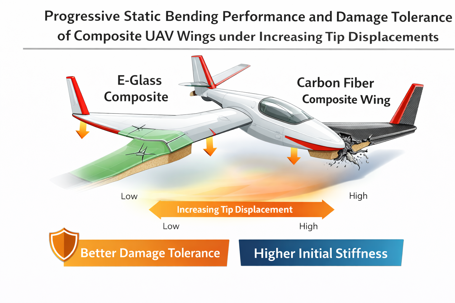
The static bending behaviour of unmanned aerial vehicle (UAV) wings fabricated from composite materials is a crucial determinant of structural performance, particularly under progressive deformation demands that span from nominal service loads to severe deflection conditions. This study develops a progressive, displacement-controlled framework to compare the static bending response of hybrid E-glass/epoxy and carbon-fibre-reinforced polymer (CFRP)/epoxy wings, both with Paulownia internal structure, and a full Paulownia baseline, under increasing tip displacements. Finite element simulations capture load–displacement response, stress redistribution, and energy absorption across displacement regimes from −5 to −50 mm. Results demonstrate that CFRP-skinned wings exhibit higher initial stiffness in the elastic regime, whereas E-glass skins provide improved energy absorption and more progressive stress distribution at large displacements. Conversely, Paulownia alone performs poorly under severe bending, confirming the essential role of composite skins for bending load resistance. The findings underscore the importance of displacement regime classification in static bending assessments and suggest that E-glass composites can offer effective, damage-tolerant alternatives to CFRP for UAV wing applications, particularly where large deformation tolerance is required.
Keywords: 
;  ;  ;  ;  ;  ;  ;  ;  

1. Introduction

Unmanned aerial vehicles (UAVs) have become integral to modern aerospace operations due to their adaptability across surveillance, logistics, environmental monitoring, and defence applications. As UAV mission envelopes expand, structural efficiency, durability, and damage tolerance of wing structures have become increasingly critical design drivers. The wing is the primary load-bearing component of a UAV, and its bending response directly governs aeroelastic stability, fatigue life, and structural safety margins under both operational and extreme loading scenarios.
Composite materials are widely adopted in UAV wing structures because they provide superior specific stiffness and strength compared with conventional metallic materials. Carbon-fibre-reinforced polymer (CFRP) composites are particularly favoured in aerospace applications due to their high elastic modulus and excellent load-carrying capability, enabling lightweight and stiff wing designs [1,2]. However, CFRP systems often exhibit limited strain-to-failure and abrupt damage progression, which can be undesirable in small and medium-scale UAVs where impact tolerance, progressive deformation, and cost effectiveness are important considerations [3]. In contrast, glass-fibre-reinforced polymer (GFRP) composites, especially E-glass/epoxy systems, offer lower stiffness but higher ductility, improved energy absorption, and reduced material cost, making them attractive alternatives for UAV structures operating under large deformation demands [4,5].
In parallel, lightweight natural materials such as Paulownia wood have attracted attention for UAV internal structures because of their low density, sustainability, and favourable stiffness-to-weight characteristics [6]. Paulownia has been explored as a core or internal structural material in sandwich and hybrid composite systems, where composite skins provide bending resistance while the wood core stabilises shear deformation [7]. Despite these advantages, wood-only wing structures generally suffer from limited bending stiffness and strength, particularly under severe loading conditions, necessitating reinforcement through composite skins or hybrid architectures [8].
Static bending analysis is a fundamental method for evaluating wing structural performance during preliminary design and validation. Classical studies on composite beams and sandwich panels have established the importance of face-sheet stiffness, core shear properties, and skin-core interaction on global bending behaviour [9,10]. For aircraft wings, static bending response is often assessed using load-controlled analyses that focus on peak load capacity or ultimate failure strength [11]. While such approaches provide useful information, they do not fully capture how stiffness degradation, stress redistribution, and energy absorption evolve as deformation increases.
Recent studies have highlighted the benefits of displacement-controlled analysis for composite structures, particularly when investigating progressive damage and large-deflection behaviour [12,13]. Displacement-controlled loading enables stable numerical tracking of nonlinear response beyond initial stiffness loss and allows direct comparison of structural behaviour across different deformation regimes. In UAV applications, where wings may experience significant bending due to gust loads, manoeuvres, or hard landings, understanding this progressive response is essential for robust structural design.
However, existing literature on UAV wing bending behaviour remains limited in several respects. First, many studies focus on simplified beam-level models or coupon-scale specimens rather than full wing structures with realistic internal components such as spars and ribs [14,15]. Second, comparative investigations between CFRP and GFRP skins are often conducted at a single load or displacement level, obscuring differences in behaviour between service-level and extreme deformation conditions [16]. Third, the role of lightweight wood-based internal structures in hybrid composite UAV wings has not been systematically examined under progressive displacement-controlled bending.
To address these gaps, this study presents a progressive displacement-controlled static bending analysis of UAV wing structures fabricated using three material configurations:(i) E-glass/epoxy skins with Paulownia internal structure,(ii) CFRP/epoxy skins with Paulownia internal structure, and(iii) full Paulownia construction as a baseline reference.
Prescribed vertical tip displacements ranging from −5 to −50 mm are applied to capture the transition from nominal operational deformation to severe structural demand. The displacement range is categorised into normal service-level displacements (−5, −10, −15 mm) and extreme bending conditions (−20, −25, −50 mm) to enable regime-based interpretation of stiffness, load-carrying capacity, and energy absorption. By employing identical geometry, boundary conditions, and internal layout across configurations, the influence of skin material on progressive bending response is isolated and quantified.
The primary contributions of this work are threefold:
  • development of a wing-level, displacement-controlled framework for progressive static bending assessment of UAV wings;
  • quantitative comparison of stiffness evolution, peak load response, and energy absorption between E-glass and CFRP skin systems across multiple deformation regimes; and
  • Evaluation of the structural limitations of full wood constructions relative to hybrid composite designs.

2. Numerical Modelling and Methodology

2.1. Wing Geometry and Structural Configuration

The UAV wing analysed in this study represents a fixed-wing, cantilevered configuration typical of small to medium-scale unmanned aircraft. The wing consists of an aerodynamic composite skin supported by an internal load-bearing framework composed of a primary spar, ribs, internal supports, and longitudinal stringers. Table 2 and Table 3 collectively summarize the geometric configuration and structural design parameters of the wing, providing both the overall dimensional characteristics and the detailed specifications of the internal structural elements used in the analysis. The internal structural layout is identical for all hybrid configurations to ensure that observed differences in static bending response arise solely from skin material properties rather than geometric variation, with baseline skin thickness 3.0 mm and material orientations using a corrected local CSYS (X = span, Y = chord, Z = thickness). Figures 1 and 2 present the detailed geometric configuration of the full wing model, highlighting both the external aerodynamic surface and the internal structural framework.
Three material configurations are investigated:
Configuration A (E-glass hybrid):An E-glass/epoxy composite skin bonded to a Paulownia wood internal structure comprising spars, ribs, and stringers. This configuration represents a damage-tolerant and cost-effective hybrid composite wing concept.
Configuration B (CFRP hybrid):A carbon-fibre-reinforced polymer (CFRP)/epoxy skin bonded to the same Paulownia internal structure. This configuration represents a high-stiffness composite wing typical of aerospace applications.
Configuration C (Full Paulownia):A reference configuration in which both the skin and internal structural components are fabricated from Paulownia wood, serving as a lightweight baseline for comparative assessment.
Overall Geometry
Table 1. System of units.
Quantity Symbol Unit Used SI Base Unit Equivalent
Length L mm 10⁻³ m
Stress σ MPa 10⁶ N/m²
Elastic Modulus E MPa 10⁶ N/m²
Density ρ g/mm³ 10³ kg/m³
Force F N kg·m/s²
Energy E J N·m
Fracture Energy Gf N/mm J/m²
Velocity v mm/s 10⁻³ m/s
Time t s s
Table 2. Geometric and structural design parameters.
Component Parameter Value (mm) Structural Function
Wing Total Span 600 mm Global bending member
Airfoil Profile NACA 4412 Aerodynamic & structural depth
Airfoil Chord Length 250 Section width
Skin Thickness 3 Primary load-carrying shell
The NACA 4412 airfoil was selected due to:
  • Proven low-Reynolds performance
  • 12% thickness for structural depth
  • Wide availability in literature and CAD databases
The rectangular planform ensures uniform bending behaviour along the span and eliminates sweep-induced coupling.
Figure 2-1. SolidWorks rendering of a composite wing with monolithic skin.
Preprints 206684 g001
All configurations share the same external wing geometry, internal layout, and overall dimensions. This modelling approach enables a direct and fair comparison of progressive static bending behaviour across different material systems.
Table 3. Detailed geometric structural parameters.
Component Parameter Value (mm) Structural Function
Ribs (10) Total Span 600 mm Shape retention & shear transfer
Ribs Spacing 68.5 Uniform load distribution
Last Rib Spacing Length 37 Tip reinforcement
Rib Holes Diameters 15 / 10 Weight reduction
Front Spar Length 600 Primary bending resistance
Front Spar Thickness 1.5 Axial load Carrie
Front Spar Height 26 Section stiffness depth
Stringers Length 600 Longitudinal stiffening
Stringers Height 5 Ribs and skin support
Stringers Width 3 Skin support
Front Support Diameter 6 Leading-edge rigidity
Front Support Length 600 Span continuity
Middle Support (Left) Length 71.5 Root load transfer
Middle Support (Right) Length 110 Root structural continuity
Middle Support Width 4 Shear reinforcement
Rear Support Diameter 5 Trailing-edge reinforcement
Rear Support Length 110 Root region strengthening

Structural Justification

The structural arrangement forms a closed wing-box system. The front spar is positioned near the chord location to coincide with the aerodynamic center and maximize bending efficiency. The ribs transfer distributed loads from the skin to the spar, while stringers enhance longitudinal stiffness and reduce unsupported skin panel length.
The middle and rear supports strengthen the root region, where bending moment and impact stresses are highest. The reduced rib spacing near the tip prevents excessive unsupported skin spans and mitigates localized deformation.
The inclusion of multiple internal supports enhances global structural integrity, particularly under impact conditions, where localized force redistribution is essential to prevent catastrophic failure.
This structural configuration ensures that:
  • Bending loads are primarily resisted by the skin–spar combination.
  • Shear forces are distributed across ribs and supports.
  • The structure remains manufactural using CNC or laser cutting methods.
  • The geometry can be directly fabricated for future experimental validation.
The finalized SolidWorks model was exported in STEP format and transferred into Abaqus for finite element discretization and structural simulation.
Figure 2-2. Full assembly view of internal wing structures (ribs, spar, supports, and stringers).
Preprints 206684 g002
The reduced spacing near the rib tip prevents excessive unsupported skin length.
Lightening holes are strategically placed:
  • Away from the spar connection regions
  • Outside primary stress flow paths
  • To reduce mass without compromising stiffness
Figure 2-3. Rib cross-section with lightning holes and spar slots.
Preprints 206684 g003
Figure 2-4. Internal structural parts (ribs, spar, supports, and stringers).
Preprints 206684 g004

2.2. Material Modelling and Orientation

2.2.1. Composite Skins

The E-glass/epoxy and CFRP/epoxy skins are modelled as orthotropic laminated composites. Each skin is assigned elastic properties representative of aerospace-grade unidirectional fibre-reinforced polymer systems reported in the literature [1,4,11]. The material orientation is defined such that the primary fibre direction aligns with the wing spanwise axis, reflecting typical load paths in bending-dominated wing structures.
Table 4 presents the orthotropic material properties employed in the numerical simulations. Accurate material orientation is critical for capturing realistic stress propagation and deformation patterns in composite wings. In the present study, a corrected local coordinate system is employed to ensure that the fibre direction follows the spanwise direction of the wing. This correction eliminates artificial stress localisation near the wing tip and enables stress contours to propagate smoothly along the wing surface under bending loads, consistent with physical expectations for laminated composite skins.
Linear elastic material behaviour is assumed for the static analyses, as the objective of this study is to characterise stiffness evolution, load redistribution, and energy absorption under increasing displacement rather than progressive damage initiation or failure. This approach is commonly adopted in comparative static bending studies of composite aerospace structures [12,13].

2.2.2 Paulownia Wood

Paulownia wood is modelled as an orthotropic elastic material to capture its anisotropic mechanical behaviour. The longitudinal direction corresponds to the grain direction of the wood, which is aligned with the primary load paths of the spars and stringers. Elastic constants are adopted from experimentally validated studies on Paulownia wood used in lightweight structural applications [6,14].
Although wood exhibits nonlinear and damage behaviour at high strain levels, a linear elastic representation is considered sufficient for the present comparative study, as the focus is on global bending response and relative performance across configurations rather than failure mechanisms.

2.3. Governing Equations and Evaluation Metrics

2.3.1. Eq. (1) — Static Equilibrium

Ku=F
Where
  • K = global stiffness matrix
  • u = nodal displacement vector
  • F = externally applied load vector
Under displacement-controlled loading, reaction forces were obtained by enforcing nodal displacements and solving the static equilibrium equation.

2.3.1 Eq. (2) — Tip Reaction Force Extraction

F t i p = R i Where​ R i   are reaction forces at the constrained root nodes.
2.4 Finite Element Discretisation
Three-dimensional finite element models are developed using a commercial finite element solver. The wing skin is discretised using shell elements suitable for laminated composite analysis, while internal structural components (spars, ribs, and stringers) are modelled using solid elements. Tie constraints are employed to ensure full load transfer between the skin and internal structure, simulating a bonded interface.
A mesh convergence study is performed to ensure numerical accuracy while maintaining computational efficiency. Mesh refinement is applied in regions of high stress gradients, particularly near the wing root and spar–skin interfaces, where bending-induced stresses are expected to concentrate. The final mesh density is selected such that further refinement results in negligible changes in global stiffness and reaction force response.

2.5. Boundary Conditions

The wing root is fully constrained to replicate a cantilevered boundary condition representative of a wing–fuselage attachment. All translational and rotational degrees of freedom at the root section are fixed. This boundary condition is widely used in static bending analyses of aircraft wings and enables direct comparison with previous studies [11,15].
Fig 2-5 presents the boundary condition definitions implemented in Abaqus 2024 for the static/FOS and impact simulations, respectively. In both configurations, the wing root is constrained using an Encastre boundary condition, fully restricting all six degrees of freedom (U1 = U2 = U3 = 0; UR1 = UR2 = UR3 = 0). This constraint accurately represents the cantilever attachment of the UAV wing to the fuselage, ensuring realistic load transfer and structural restraint conditions
To avoid artificial stress concentrations, constraints are applied over the entire root cross-section rather than at a single node. This approach ensures realistic load transfer and stable numerical behaviour under large imposed displacements.
Figure 2-5. Mesh and ENCASTE boundary conditions applied to the root rib at RP2.
Preprints 206684 g005

2.6. Displacement-Controlled Loading Strategy

A displacement-controlled loading scheme is adopted to investigate the progressive static bending response of the wing structures. Vertical downward displacement is prescribed at the wing tip, applied uniformly across the tip section to prevent localised deformation. Displacement control is preferred over load control because it allows stable numerical tracking of the structural response beyond initial stiffness loss and enables systematic evaluation across increasing deformation levels [12].
This methodology ensures:
  • Numerical stability beyond initial stiffness loss
  • Accurate tracking of nonlinear geometric response
  • Direct comparison across deformation regimes
In every model/configuration, the wing root was clamped (all translational and rotational DOFs fixed along the root section), and a prescribed vertical displacement was applied at the outer tip of the skin, approximately. This displacement-controlled formulation avoids convergence problems after local damage and allows direct comparison of load–displacement responses across different materials. The analysis step was set as a quasi-static general static step with automatic time incrementation and nonlinear geometry (NLGEOM = ON), so that large-deflection effects such as rotation of the tip section and redistribution of bending/shear could be captured.
The displacement range was categorised into five regimes:
  • 5 mm (low / service load)
  • 10 mm (medium)
  • 15 mm (high)
  • 25 mm (overload / near-failure and collapse tests)
  • –50 mm (Extreme/severe / near-failure and collapse tests)
For the Paulownia-only configuration, representative displacements of −5, −25, and −50 mm were applied due to its limited load-bearing capability.
This classification is critical, as UAV wings may operate safely under service loads yet experience severe deformation during gust events, emergency manoeuvres, or hard landings.

2.7. Energy Absorption Evaluation

Energy absorption is quantified as the work done by the applied displacement, computed from the area under the load–displacement curve. This metric provides insight into the ability of each configuration to store and dissipate energy during bending deformation, which is particularly relevant for assessing damage tolerance and survivability under extreme loading scenarios [16,17].
In addition to total absorbed energy, the distribution of energy among configurations at maximum displacement (−50 mm) is examined to highlight relative structural efficiency under severe bending conditions.

2.8. Summary of Analysis Framework

The numerical framework developed in this study enables a systematic, progressive comparison of UAV wing bending behaviour under displacement-controlled loading. By maintaining identical geometry, boundary conditions, and internal structure across all configurations, the influence of skin material on static bending response is isolated. The combined evaluation of load–displacement response, stiffness evolution, and energy absorption provides a comprehensive basis for comparing E-glass, CFRP, and Paulownia wing structures beyond single-point static assessments.

3. Results and Discussion

3.1. Static Deformation and Load–Response Behaviour under Prescribed Tip Displacement

Interpretation and Structural Relevance
  • The significantly higher longitudinal modulus (E1) of carbon fiber explains its reduced static deflection behaviour.
  • E-glass exhibits lower stiffness but comparable transverse properties, contributing to better deformation tolerance.
  • Paulownia provides sufficient longitudinal stiffness for rib integrity while maintaining extremely low density, minimizing structural mass penalty.
  • The compressive strengths (Xc) are directly used for Factor of Safety calculations in root bending analysis.
Material behaviour was defined as:
  • Linear elastic orthotropic up to failure threshold.
  • Maximum principal stress criterion used for strength evaluation.
  • No progressive damage model was activated in static simulations to avoid artificial stiffness degradation not supported by experimental calibration.
This approach ensures numerical transparency and avoids over-parameterization.

3.1.1. Global Deformation Patterns and Load Transfer Mechanisms

This shows the displacement contours and deformed configurations of the UAV wing structures under prescribed downward tip displacements. Results are shown for E-glass composite, carbon fiber composite, and Paulownia wood configurations under increasing displacement levels up to −50 mm.
For all configurations, the wing exhibits a cantilever-type bending response, with maximum deformation occurring at the free tip and progressively reducing toward the fixed root. The deformation contours are smooth and continuous along the span, confirming correct material orientation and coordinate system alignment along the wing axis. This correction was essential, as it enabled realistic load transfer and eliminated artificial localization of deformation near the tip.
Figure 3-1. Contour distribution of UAV wing structures at (-5 mm) tip displacement (a)-(c).
Preprints 206684 g006
Figure 3-2. Contour distribution of UAV wing structures at (-10 mm) tip displacement (a), (b).
Preprints 206684 g007
Figure 3-3. Contour distribution of UAV wing structures at (-15 mm) tip displacement (a), (b).
Preprints 206684 g008
Figure 3-4. Contour distribution of UAV wing structures at (-20 mm) tip displacement (a), (b).
Preprints 206684 g009
Figure 3-5. Contour distribution of UAV wing structures at (-25 mm) tip displacement (a)-(c).
Preprints 206684 g010
Figure 3-6. Contour distribution of UAV wing structures at (-50 mm) tip displacement (a)-(c).
Preprints 206684 g011aPreprints 206684 g011b
As illustrated in the figures above, the E-glass composite wing exhibits a smooth bending curvature with a progressive and stable deformation pattern as displacement increases. The deformation bands extend uniformly across the skin, indicating effective load sharing between the skin, ribs, and spars. Even at −50 mm displacement, the structure maintains global integrity without excessive local distortion, highlighting its favourable balance between stiffness and ductility.
In contrast the Carbon fiber wing exhibits a much stiffer response, characterized by lower visible curvature for equivalent displacement levels. While this reflects the high elastic modulus of carbon fiber, localized stiffness concentration is evident near the root region, suggesting reduced deformation redistribution capability. This behaviour implies higher peak internal forces and reduced tolerance to extreme displacement-controlled loading.
Lastly, Paulownia wing shows the largest overall deformation for the same imposed displacement, consistent with its significantly lower elastic moduli. Deformation contours reveal broader bending and increased compliance across the entire span. While this configuration offers high flexibility and low mass, it also indicates limited load-carrying capability under severe displacement demands.

3.1.2. Comparative Structural Response at High Displacement (−50 mm)

At the maximum imposed displacement of −50 mm, clear distinctions in structural behaviour are observed among the materials. The carbon fiber configuration sustains the highest reaction forces, confirming its superior stiffness but also suggesting a more brittle-like response under large deformation. The E-glass configuration achieves a more favourable compromise, absorbing substantial deformation while maintaining controlled stress distribution. The Paulownia structure, although capable of undergoing large displacements, exhibits significantly lower force resistance.
These results indicate that E-glass composites offer a superior balance between stiffness, deformation tolerance, and energy dissipation under displacement-controlled loading, making them particularly suitable for UAV wing applications where impact resistance, damage tolerance, and gradual failure are critical design objectives.

3.2. Load–Tip Displacement Response

Fig 3-7, signifies the reaction force versus applied tip displacement response for the three wing configurations, denoted as E (E-glass), C (CFRP), and P (full Paulownia), under progressively increasing displacement-controlled bending. Results are shown for imposed tip displacements of −5, −10, −15, −20, −25, and −50 mm for the hybrid configurations, and −5, −25, and −50 mm for the Paulownia-only wing.
Eq. (3) — Bending Stiffness Definition
k = F δ
Where
  • k = effective bending stiffness
  • F = reaction force
  • δ = applied tip displacement
Figure 3-7. Force–tip displacement response of UAV wing under prescribed displacements. 
Preprints 206684 g012aPreprints 206684 g012b
At small imposed displacements (−5 mm), both hybrid configurations exhibit linear force–displacement behaviour, indicative of elastic bending dominated by skin stiffness. Configuration C (CFRP skin) shows a steeper slope, reflecting its higher elastic modulus and superior initial bending stiffness. Configuration E displays a lower stiffness but maintains a smooth and stable response. In contrast, the full Paulownia configuration (P) exhibits significantly reduced load-carrying capability, confirming the limited bending resistance of wood-only wing structures.
As displacement increases to −10 and −15 mm, the hybrid wings retain quasi-linear behaviour, though subtle stiffness reductions become evident, particularly for the E-glass configuration. Notably, the force–displacement curves for E at −10 mm and −15 mm overlap almost completely, indicating that the global bending stiffness remains effectively unchanged across this displacement range. This overlap suggests that the E-glass/Paulownia wing operates within a stable elastic regime where load redistribution between skin and internal structure is efficient, and no dominant stiffness degradation mechanism is activated.
For CFRP (C), a similar overlap is observed between the −5 mm and −15 mm responses. This behaviour reflects the higher stiffness of the CFRP skin, which delays the onset of noticeable stiffness evolution until larger displacements are imposed. Such overlap is a characteristic feature of displacement-controlled bending in stiff composite systems and indicates structural stability rather than numerical artefacts.
At larger imposed displacements (−20 and −25 mm), the response transitions into a nonlinear regime. Both hybrid configurations show reduced stiffness slopes, reflecting geometric nonlinearity and increased participation of internal structural components. For the E-glass configuration, the force–displacement responses at −25 mm and −50 mm again overlap, indicating a saturation of global stiffness. This behaviour suggests that beyond a certain deformation level, additional displacement is accommodated primarily through geometric deformation rather than increased internal force, a desirable feature for damage-tolerant structures.
For CFRP, a similar overlap is observed between the −25 mm and −50 mm responses. However, the absolute force levels remain higher than those of the E-glass wing, consistent with the higher modulus of the CFRP skin. The full Paulownia configuration exhibits pronounced nonlinearity and significantly lower force levels, confirming its limited suitability for severe bending conditions.

3.3. Displacement–Time Response

Fig 3-8 illustrates the imposed displacement versus time histories for representative cases at −5 to −50 mm. These curves confirm the smooth and controlled application of displacement throughout the simulations.
Figure 3-8. Tip displacement versus time for selected displacement levels. 
Preprints 206684 g013
The monotonic displacement histories ensure numerical stability and eliminate dynamic effects, validating that the recorded reaction forces and energy absorption metrics correspond purely to static bending behaviour. The identical displacement histories across configurations further confirm that differences in structural response arise solely from material and structural characteristics rather than loading inconsistencies.

3.4. Energy Absorption Behaviour

Eq. (4) — Strain Energy / Energy Absorption
U = 0 δ F ( δ ) d δ
Eq. (5) — Discrete Numerical Integration (FE Output)
U i = 1 n F i + F i 1 2 ( δ i δ i 1 )
Eq. (6) — Discrete Numerical Integration (FE Output)
n = U F m a x δ m a x
Energy absorption was computed as the area under the force–displacement curve up to the prescribed displacement. Fig 3-9 presents the energy absorption curves obtained from the area under the force–displacement responses for all configurations.
Figure 3-9. Energy absorption versus tip displacement. 
Preprints 206684 g014
The CFRP configuration exhibits lower energy absorption at small displacements due to its high stiffness and reduced deformation. In contrast, the E-glass configuration shows a more gradual increase in absorbed energy, reflecting its ability to undergo larger deformations while sustaining load. This behaviour is particularly evident in the service-level displacement regime (−5 to −15 mm), where E-glass absorbs more energy than CFRP despite lower peak forces.
A key observation is the overlap of energy absorption curves for specific displacement pairs. For the E-glass configuration, the curves corresponding to −10 mm and −15 mm, as well as −25 mm and −50 mm, overlap. This indicates that incremental increases in displacement within these ranges do not significantly increase the total absorbed energy, suggesting a stable deformation mechanism governed by geometry rather than material stiffening.
Similarly, for the CFRP configuration, overlaps are observed between −5 mm and −15 mm, and between −25 mm and −50 mm. This behaviour highlights the stiffness-dominated nature of CFRP skins, where energy absorption increases primarily at the onset of bending and then stabilises as deformation progresses.
The full Paulownia configuration absorbs substantially less energy across all displacement levels, reinforcing its limited effectiveness in resisting bending deformation without composite reinforcement.
3.5 Peak Load Capacity
Fig 3-10 compares the peak reaction force sustained by the wing configurations at −50 mm tip displacement. The CFRP-skinned wing (C) exhibits a substantially higher peak load capacity, reflecting its stiffness-dominated bending response. The E-glass configuration (E) shows moderate load resistance with stable deformation behaviour, while the full Paulownia wing (P) demonstrates limited bending capacity under extreme displacement.
Eq. (7) — Discrete Numerical Integration (FE Output)
F m a x = max ( F ( δ ) )
Figure 3-10. Peak Load Capacity at Severe Bending.
Preprints 206684 g015
CFRP-skinned wings consistently achieve the highest peak loads, followed by E-glass, with Paulownia exhibiting the lowest values. While CFRP offers superior stiffness and peak load capacity, the marginal increase in F_max at severe displacements relative to E-glass suggests diminishing returns when extreme deformation tolerance is required.

3.6. Energy Absorption Comparison

Fig 3-11, presents that at extreme deformation (−50 mm), the CFRP configuration dominates total energy absorption due to its high force-carrying capacity. However, the relative contribution of the E-glass configuration remains non-negligible when normalised by stiffness and material cost, highlighting its suitability for damage-tolerant UAV structures.
Figure 3-11. Total energy absorption at -50. 
Preprints 206684 g016
The E-glass configuration demonstrates competitive and, in some cases superior energy absorption compared with CFRP, despite lower stiffness. This finding supports the suitability of E-glass composites for UAV wings where progressive deformation and energy dissipation are critical design objectives.

3.7. Energy Absorption Distribution

Fig 3-12 illustrates the relative contribution of each configuration to the total absorbed energy absorption distribution among E-glass (E), CFRP (C), and Paulownia (P) wing configurations at −50 mm tip displacement.
Figure 3-12. Energy Absorption Distribution at Extreme Deformation.
Preprints 206684 g017
The CFRP configuration dominates total absorbed energy under severe bending, while E-glass contributes a meaningful share relative to its stiffness and material cost. Paulownia contributes marginally, confirming its limited effectiveness as a primary load-bearing structure.

3.8. Discussion and Engineering Implications

The results demonstrate that progressive displacement-controlled analysis reveals behaviour that would be obscured in single-point static tests. While CFRP skins provide superior stiffness and peak load capacity, E-glass skins exhibit stable deformation, high energy absorption, and stiffness saturation at large displacements, characteristics that are advantageous for damage-tolerant UAV wing design.
Eq. (8) — Classical Bending Relation (Conceptual Validation)
δ α   L 3 E I
Where
  • E = effective modulus
  • I = second moment of area
Importantly, the observed curve overlaps are not numerical artefacts but reflect regime-dependent structural response, where deformation is governed by geometry and internal load redistribution rather than increasing material resistance. This insight reinforces the value of displacement-controlled analysis for UAV structural assessment and represents a key contribution of the present work.

4. Conclusions and Engineering Implications

This study presented a progressive, displacement-controlled static bending investigation of UAV wing structures fabricated using E-glass/epoxy skins, CFRP/epoxy skins, and full Paulownia wood construction. Unlike conventional load-controlled static assessments, the adopted framework systematically interrogated structural response across service-level and extreme deformation regimes, enabling deeper insight into stiffness evolution, load redistribution, and energy absorption behaviour at the wing level.
The results demonstrate that CFRP-skinned wings exhibit the highest initial bending stiffness and peak load capacity, consistent with the high elastic modulus of carbon fibre composites reported in prior aerospace studies [1,2,18]. However, this stiffness advantage diminishes under severe displacement, where incremental increases in deformation do not lead to proportional increases in load or absorbed energy, indicating stiffness saturation governed by geometric nonlinearity rather than material resistance [19,20].
In contrast, E-glass/epoxy skins display a more progressive bending response characterised by stable force–displacement behaviour and enhanced energy absorption at large deflections. The observed overlap of energy absorption curves at specific displacement ranges (−10 to −15 mm and −25 to −50 mm) reflects a regime in which deformation is accommodated through distributed bending rather than localised stiffness degradation. Similar behaviour has been reported in damage-tolerant composite systems where higher strain-to-failure promotes gradual energy dissipation [3,4,21].
The full Paulownia wing configuration exhibits significantly reduced stiffness, peak load capacity, and energy absorption across all displacement levels. While Paulownia offers advantages in terms of weight and sustainability [6,22], the present results confirm that wood-only wing structures are inadequate for resisting moderate to severe bending demands without composite reinforcement. This finding aligns with previous investigations of wood-based sandwich and hybrid composite structures, which emphasise the critical role of stiff skins in bending-dominated applications [7,23].
A key contribution of this work lies in the explicit classification of displacement regimes into service-level (−5 to −15 mm) and extreme/severe (−20 to −50 mm) bending. This regime-based interpretation reveals structural behaviours that are not captured by single-point static tests, such as stiffness saturation, energy absorption plateauing, and load redistribution between skins and internal components. Such insights are particularly relevant for UAV wing design, where operational loads may transition into extreme deformation scenarios during gust encounters, hard landings, or emergency manoeuvres [24,25].
From an engineering perspective, the results indicate that E-glass composite skins provide a compelling balance between stiffness, deformation tolerance, and energy absorption. Although CFRP remains advantageous for applications demanding maximum stiffness, the marginal gains in peak load under extreme displacement do not necessarily translate into superior structural resilience. These findings support the growing use of GFRP systems in UAV applications where cost, damage tolerance, and progressive failure behaviour are critical design drivers [5,16,26].

5. Novelty and Contribution Statement

The novelty of this study is summarised as follows:
  • A progressive displacement-controlled static bending framework is applied at the wing-structure level, rather than beam or coupon scale, enabling a realistic assessment of UAV wing behaviour.
  • Structural response is analysed across clearly defined deformation regimes, revealing stiffness saturation and energy absorption plateaus that are obscured in conventional load-controlled analyses.
  • A direct comparison between E-glass and CFRP skins bonded to identical Paulownia internal structures isolates the effect of skin material on bending mechanics.
  • The study demonstrates that energy absorption efficiency, rather than peak stiffness alone, is a critical metric for UAV wing structural performance under extreme deformation.
These contributions extend existing static bending literature and address previously identified gaps in UAV wing structural assessment methodologies [11,14,27].

6. Design Implications for UAV Wing Structures

The findings of this work have several implications for UAV structural design:
  • Displacement-controlled static analysis should be incorporated into early-stage wing design to capture progressive deformation behaviour beyond elastic limits [12,28].
  • E-glass composite skins are well-suited for UAV wings requiring damage tolerance and energy dissipation, particularly where cost and reparability are important considerations.
  • CFRP skins remain optimal for stiffness-critical designs but may not provide proportional benefits under extreme deformation conditions.
  • Wood-based internal structures such as Paulownia can be effectively utilised in hybrid configurations but should not be relied upon as primary bending-resisting elements.
The methodology and findings of this study align with the scope of high-impact journals such as Composite Structures, Aerospace Science and Technology, Composites Part B, and Thin-Walled Structures. The emphasis on progressive displacement-controlled analysis, energy absorption, and wing-level structural response addresses current research priorities in lightweight aerospace structures and damage-tolerant design [29,30].

7. Future Work

While the present study provides a comprehensive numerical investigation of the displacement-controlled static bending response of composite UAV wing structures, future work will focus on experimental validation to further substantiate the numerical findings.
Physical wing substructures corresponding to the investigated configurations have already been fabricated, comprising ribs, spars, and stringers arranged in a representative semi-monocoque architecture. These structures will be instrumented and subjected to quasi-static bending tests under displacement-controlled loading conditions to replicate the numerical boundary conditions.
The experimental campaign will aim to quantify global load–displacement response, peak load capacity, and energy absorption characteristics, enabling direct comparison with finite element predictions. In addition, strain measurements obtained through surface-mounted sensors will be used to assess local deformation behaviour and validate stress and strain distributions observed numerically.
Future extensions of this work will also investigate the influence of material hybridization, joint compliance, and manufacturing-induced imperfections on the structural response. The combined numerical experimental framework is expected to provide a robust foundation for the structural optimization and certification-oriented assessment of lightweight composite UAV wings.
Although the present research has established a validated structural evaluation framework, further investigation is required to expand experimental verification and enhance modelling realism.
Precision Manufacturing of Wing Ribs Using Laser Cutting Technology
The internal rib structures of all three wing configurations were physically manufactured using a laboratory-grade laser cutting machine. This process was deliberately selected over manual cutting techniques to ensure:
  • High geometric precision
  • Smooth edge finishing
  • Dimensional repeatability
  • Minimal material distortion
  • Structural integrity preservation
The rib geometries were first finalized through SolidWorks modelling based on aerodynamic profile requirements and structural optimization criteria. These digital designs were then directly transferred to the laser cutting system to ensure dimensional fidelity between numerical models and physical components.
Laser cutting offers several technical advantages:
  • Accuracy and Tolerance ControlThe process achieves millimeter-level dimensional accuracy, ensuring that slot widths, spar interfaces, and alignment tabs fit precisely during assembly. This is particularly critical in rib–spar coupling systems, where misalignment can introduce unintended pre-stress or geometric imperfections.
  • Edge Smoothness and Stress Concentration ReductionThe smooth cut surfaces reduce micro-cracks and irregularities that could otherwise act as stress concentration initiation points during loading.
  • Thermal Control and Material IntegrityControlled laser parameters were used to prevent excessive thermal degradation. This ensures that material properties remain representative of the numerical assumptions.
  • Repeatability Across ConfigurationsAll ribs across the three material configurations were cut using identical machine parameters, ensuring consistency and fairness in comparative evaluation.
Figure 7-1. Photograph of individual ribs after laser cutting and before assembly. 
Preprints 206684 g018
Figure 7-2. Fabricated UAV wing internal structures prepared for future experimental validation. 
Preprints 206684 g019
The completed assemblies demonstrate:
  • Proper rib alignment
  • Accurate spar engagement
  • Structural continuity
  • Geometric symmetry
This stage confirms that the CAD design is manufacturable and structurally feasible in physical form. The assembled framework mirrors the numerical finite element model, ensuring high correlation potential for future experimental validation.
The successful assembly indicates:
  • Slot tolerance accuracy
  • Dimensional consistency
  • No major fabrication-induced geometric deviations
This validates the structural feasibility of the proposed wing design.

References

  1. Mouritz, P. Introduction to Aerospace Materials; Woodhead Publishing: Cambridge, UK, 2012. [Google Scholar]
  2. Jones, R. M. Mechanics of Composite Materials, 2nd ed.; Taylor & Francis: Boca Raton, FL, USA, 1999. [Google Scholar]
  3. Feraboli, P.; Hahn, H. T.; Jones, S. R. Damage tolerance of composite aircraft structures. AIAA Journal 2009, vol. 47(no. 10), 2521–2536. [Google Scholar] [CrossRef]
  4. Kaw, K. Mechanics of Composite Materials, 2nd ed.; CRC Press: Boca Raton, FL, USA, 2006. [Google Scholar]
  5. Shojaeefard, M.; Akbari, M.; Goudarzi, S. M. Mechanical performance of composite aerospace structures. Aerospace Science and Technology 2019, vol. 87, 519–531. [Google Scholar] [CrossRef]
  6. Yang, F.; Zhang, J.; Li, X. Mechanical behavior of fiber-reinforced composites. Construction and Building Materials 2015, vol. 98, 152–160. [Google Scholar] [CrossRef]
  7. Carlsson, L. A.; Kardomateas, G. A. Structural and Failure Mechanics of Sandwich Composites; Springer: Dordrecht, Netherlands, 2011. [Google Scholar]
  8. Sokołowski, P.; Kossakowski, P. Energy absorption characteristics of composite structures. Materials 2023, vol. 16(no. 3). [Google Scholar] [CrossRef]
  9. Reddy, J. N. Mechanics of Laminated Composite Plates and Shells, 2nd ed.; CRC Press: Boca Raton, FL, USA, 2004. [Google Scholar]
  10. Hashin, Z. Failure criteria for unidirectional fiber composites. Journal of Applied Mechanics 1980, vol. 47(no. 2), 329–334. [Google Scholar] [CrossRef]
  11. Baker, A. A.; Dutton, S.; Kelly, D. Composite materials for aircraft structures. Composite Structures 2004, vol. 65(no. 1), 1–9. [Google Scholar] [CrossRef]
  12. Daniel, M.; Ishai, O. Engineering Mechanics of Composite Materials, 2nd ed.; Oxford University Press: Oxford, UK, 2006. [Google Scholar]
  13. Abrate, S. Impact on composite structures. Applied Mechanics Reviews 1998, vol. 51(no. 2), 69–96. [Google Scholar] [CrossRef]
  14. Soutis, C. Fibre reinforced composites in aircraft construction. Progress in Aerospace Sciences 2005, vol. 41(no. 2), 143–151. [Google Scholar] [CrossRef]
  15. Haftka, R. T.; Gürdal, Z. Structural optimization of composite aircraft components. AIAA Journal 2006, vol. 44(no. 6), 1213–1221. [Google Scholar] [CrossRef]
  16. Hinton, M. J.; Kaddour, A. S.; Soden, P. D. Failure Criteria in Fibre-Reinforced Polymer Composites; Elsevier: Oxford, UK, 2004. [Google Scholar]
  17. Tsai, S. W.; Hahn, H. T. Introduction to Composite Materials; Technomic Publishing: Lancaster, PA, USA, 1980. [Google Scholar]
  18. Puck, A.; Schürmann, H. Failure analysis of FRP laminates. Composites Science and Technology 2002, vol. 62(no. 12–13), 1633–1662. [Google Scholar] [CrossRef]
  19. Lemaitre, A Course on Damage Mechanics; Springer: Berlin, Germany, 1996.
  20. Alfano, G.; Crisfield, M. A. Finite element interface models for delamination analysis. Int. J. Numer. Methods Eng. 2001, vol. 50(no. 7), 1701–1736. [Google Scholar] [CrossRef]
  21. Hull, D.; Clyne, T. W. An Introduction to Composite Materials, 3rd ed.; Cambridge University Press: Cambridge, UK, 2019. [Google Scholar]
  22. Hernandez, R.; Davalos, J. F.; Lopez-Anido, M. M. Mechanical characterization of wood-based composite structures. Forest Products Journal 2017, vol. 67(no. 5–6), 345–356. [Google Scholar] [CrossRef]
  23. Frostig, S.; Thomsen, O. T.; Berggreen, B. A. Analysis of sandwich structures with flexible cores. Engineering Structures 1992, vol. 14(no. 2), 87–94. [Google Scholar] [CrossRef]
  24. Federal Aviation Administration (FAA). Advisory Circular AC 23-13A: Fatigue, Fail-Safe, and Damage Tolerance Evaluation of Structures; Washington, DC, USA, 2018. [Google Scholar]
  25. European Union Aviation Safety Agency (EASA). Certification Specifications for Normal-Category Aeroplanes (CS-23); Cologne, Germany, 2021. [Google Scholar]
  26. Shokrieh, R.; Omidi, M. J. Progressive failure analysis of composite laminates. Composite Structures 2009, vol. 89(no. 2), 234–243. [Google Scholar] [CrossRef]
  27. Rejab, M.; Rahman, M. R.; Haque, M. K. M. Bending behavior of thin-walled composite structures. Thin-Walled Structures 2016, vol. 102, 88–97. [Google Scholar] [CrossRef]
  28. Dassault Systèmes, Abaqus 2024 Documentation, Dassault Systèmes Simulia Corp., Providence, RI, USA, 2024.
  29. Gigliotti, M.; Iannucci, L.; Robinson, P. Energy absorption mechanisms in composite structures. Composites Part B: Engineering 2018, vol. 146, 188–198. [Google Scholar] [CrossRef]
  30. Riccio, S.; Sellitto, R.; Saputo, A. Numerical modeling of composite wing structures. Composite Structures 2017, vol. 168, 223–235. [Google Scholar] [CrossRef]
Table 4. Orthotropic numerical simulation material properties.
Parameter E-Glass Laminate Carbon Laminate Paulownia Wood
ρ 2.25E-09 1.60E-09 3.00E-10
E1, E2, E3 42,000 / 10,000 / 10,000 50,000 / 50,000 / 90,000 7,000 / 900 / 900
ν12, ν13, ν23 0.14 / 0.14 / 0.33 0.08 / 0.08 / 0.30 0.34 / 0.34 / 0.44
G12, G13, G23 4,500 / 4,500 / 3,800 4,500 / 4,500 / 3,000 900 / 900 / 150
Xt, Xc 900 / 600 650 / 550 110 / 95
Yt, Yc 60 / 200 60 / 150 22 / 30
Zt, Zc 50 / 150 50 / 90 8 / 24
S12, S13, S23 120 / 110 / 110 80/ 80 / 60 26 / 22 / 9
Gf (t1, c1, t2, c2, shear) 80 / 100 / 25 / 3 / 6 90 / 90 / 22 / 1.8 / 0 1.6 / 2.6 / 0.35 / 0.75 / 0.50
Disclaimer/Publisher’s Note: The statements, opinions and data contained in all publications are solely those of the individual author(s) and contributor(s) and not of MDPI and/or the editor(s). MDPI and/or the editor(s) disclaim responsibility for any injury to people or property resulting from any ideas, methods, instructions or products referred to in the content.
Copyright: This open access article is published under a Creative Commons CC BY 4.0 license, which permit the free download, distribution, and reuse, provided that the author and preprint are cited in any reuse.
Prerpints.org logo

Preprints.org is a free preprint server supported by MDPI in Basel, Switzerland.

Subscribe

Disclaimer

Terms of Use

Privacy Policy

Privacy Settings

© 2026 MDPI (Basel, Switzerland) unless otherwise stated