

Submitted:
02 April 2026
Posted:
02 April 2026
You are already at the latest version
Abstract
One of the most promising approaches for replacing conventional power plants during the transition to clean energy is the conversion of existing coalfired power plants (CPPs) into nuclear power plants. This strategy offers numerous ecological and economic advantages. However, integrating a nuclear reactor with a steam turbine originally designed for a coal plant is far from trivial and involves significant technical challenges. The purpose of this work is to analyze and evaluate various options for coupling a HighTemperature GasCooled Small Modular Reactor (HTGR SMR) with a potentially suitable subcritical steam turbine from an existing CPP, thereby creating several repowering configurations. The main difficulties stem from the fact that the turbine was designed to operate with live steam at lower flow rates, temperatures, and pressures than those typically provided by an HTGR SMR. In addition, the feedwater temperature and pressure requirements for the HTGR SMR steam generator differ substantially from those in a CPP, leading at best to additional efficiency losses. Moreover, the overall thermal cycle layouts of the two systems are fundamentally different. Despite these challenges, technically feasible combinations can be achieved. However, determining which option is the most economically viable depends on numerous additional factors, including the specific characteristics of the individual CPP and the regulatory framework of the country in which it operates.
Keywords:
C2N
; clean energy transition
; CPP repowering
; reducing CO2 emissions
1. Introduction
In the context of clean energy transition, it is important not only to retrofit or decommission existing CPPs, especially those using lignite as fuel, to comply with environmental regulations, but also to ensure the safety and stability of the energy system [1,2]. Different technological options in three main areas are proposed and being explored to facilitate the phasing out of CPPs, summarized in Figure 1. This includes, but is not limited to:
These technologies should be evaluated based on a range of criteria, including carbon mitigation potential and other environmental impacts, technological maturity, economic feasibility, grid integration, sustainability, and their contribution to energy system stability and reliability [11,12].
There are a modest number of researches and proposed solutions in the first group but they are temporary by their nature or still quite expensive and that is why the main efforts are focused in the second group. Nevertheless the solutions in the first group are important for retaining the energy system stability and for buying the needed time for development and implementation of better and cheaper technologies for clean energy production.
The RPPs with constant production are important for the energy system stability, but they are limited by power and still quite expensive. This subgroup include power plants that use biofuels and rely on geothermal energy. It’s debatable if nuclear technologies are part of this subgroup as only most of the nuclear reactors of generation IV could be called clean and sustainable technologies.
The RPPs with fluctuating production are considered the fundament of the energy transition and although they are quite important they bring significant instability in the energy system despite technologies like solid gravity energy storage [13] or redox flow batteries [14]. Although these technologies are zero-emission they have some negative impact on the ecosystems. Also some of these technologies produce direct current which could be quite problematic for the energy system stability especially together with the fluctuating energy production. Other problem is that the most used technology is characterized with quite dark surfaces which lead to decretion of Earth’s albedo [15] and the recent researches indicate that the albedo effect is also factor in global warming [16,17,18]. These disadvantages result in searching for other possible solutions mainly in the third group, which is the least explored of the three. Despite the technological challenges, the conversion of CPPs to NPPs or HNPPs have several advantages over other options and paths for replacing or retrofitting the CPPs:
- -
- Significant mitigation of the CO₂ emissions or even zero CO₂ emissions;
- -
- NPPs produce constant and cheap energy and the significant percentage of the modern models will be able to operate in load-following mode, thus will be able to replace the CPPs not only as capacity but also as function in the energy system;
- -
- The opportunity for using existing sites, facilities and equipment offers numerous ecological and economic advantages;
- -
- NPPs has lesser impact on the ecosystems than the alternatives despite the thermal pollution which also will be reduced with the generation IV nuclear reactors (NRs);
- -
- The NRs of generation IV will characterize with enhanced safety, improved economy, minimal waste and proliferation resistance. Also it is expected that most of the types in development will have breeding ratio almost or above 1, which constitute some sort of sustainability.
CPPs to NPPs (C2N) includes four possible options [19] from which the repowering and retrofitting ones are the most attractive but also the most technology challenging. Different cases of the former [20,21] and of the latter [22,23,24,25,26] are studied, explored and analyzed but almost exclusively from economical point of view, without going into deep technological details, which make such studies one sided and quite controversial. The possible combination between NR and steam turbine (ST) from CPP depends not only from matching the thermal power but much more from the compatibly between the technological parameters and the thermal schemes. The large nuclear reactors from generations II, III, and III+ are not suitable for C2N and those from generation IV are still in development, which leaves only the available models of Small Modular Reactors (SMRs) as possible option and impose their evaluation and analysis from that perspective.
The important parameters of SMRs those development reached at least application for license are given in Table 1 below. Only one model with electrical power lower than 50 MWe is included and only one model with pre-licensed stages finished but with no actual license application yet is included. That way their parameters are guaranteed in a way and such models could be produced eventually. Boiling water reactor models are excluded because they are fit only for C2N replacement scenario.
Integral layout means that all equipment of the first circle of 2-circle NPP is integrated in one vessel. That makes the modification of the SG impossible. Two high or two low temperature of the feedwater at the SG inlet means that it is not economically feasible to use such NR models for different variants of C2N than replacement. Taking this into consideration leaves only two SMR models suitable for repowering and retrofitting options at the moment – HTR-PM and SMART. Eventually Xe-100 and CAREM models could also be suitable for this task.
The CPPs currently in operation, along with those recently decommissioned, could be classified into four groups according to the parameters of the steam produced [46]. A comparison of these parameters indicates that CPPs producing subcritical live steam are the most suitable candidates for C2N applications. CPPs of the supercritical group may also be used to some extent however the repurposing their ST is generally inefficient due to the high pressure steam required at the inlet of the ST. This means that the use of a steam compressor is necessary, which would reduce the overall efficiency of the system by several percent or approximately 10% relative efficiency. Therefore, the use of a steam compressor should only be considered if there is no other option.
The present study aims to cover some technical aspects of C2N involving NR that produces live steam with high parameters, since C2N based on NR that produces live steam with low parameters has been considered previously [19]. This could be achieved by investigating the replacement of lignite-fired SG with High Temperature Gas-cooled SMR, and HTR-PM model is suitable for the task, in a CPP unit based on an existing subcritical steam turbine. Such steam turbines are used worldwide and as has been already mentioned are more suitable for the current task. Also, some of these turbines were renovated and their life prolonged which makes them practically usable. ST from CPP commonly used in Bulgaria and the nearby countries was chosen for the current study. Based on the chosen combination, the main aspects that should be examine are: the enthalpy drops, the net efficiency and the net capacity of the modified plant. The quality of the steam shouldn’t be a problem.
2. Technological Overview and Parameters of the Chosen SMR and ST
The HTR-PM is a Generation IV, pebble-bed type modular HTGR, designed by the Institute of Nuclear and New Energy Technology (INET), Tsinghua University of China. A demonstration power plant comprising two HTR-PM modules was built near Xiqianjia village, Ningjin subdistrict, Rongcheng, Weihai, Shandong Province in China, and entered commercial operation in December 2023. HTR-PM uses helium as a coolant, graphite as a moderator, and uranium dioxide (UO2) as fuel enriched to 8.5 % in 235U [37]. The fuel is in TRISO (TRi-structural ISOtropic) form, and along with the relatively high enrichment, enables the reactor to operate in load-following mode. The reactor features inherent safety, minimal nuclear waste production, enhanced economics, and strong proliferation resistance. Additionally, the dispersed form of the fuel allows reaching a breeding ratio close to 1. The main parameters of HTR-PM NPP are presented in Table 2.
The chosen ST is intended for use in Thermal Power Plants and operates with live steam at subcritical parameters. It comprises high-pressure (HPC), intermediate-pressure (MPC) and double-flow low-pressure casings (LPC). Reheating is implemented between the HPC and MPC. The final stage of this turbine is a Baumann stage. Difficulties in adapting this ST for use with HTR-PM SMR arise from the large differences in feed water temperatures between SG of the HTR-PM and those of CPP with the chosen ST. Additionally, there are minor differences in the temperature, pressure and flow rate of the live steam. The technical parameters of the referent ST Island are presented in Table 3.
3. Simulation Methodology and Model Verification of the ST Island
The simulation modeling in this study was performed with the specialized Thermoflex software version 31 [50], developed by Thermoflow Inc. The modeling methodology is presented in Figure 2 and is based on fundamental thermodynamic principles.
Mass balance is maintained for all system components according to Equation (1):
Where: m is the mass flow rate and the subscripts in and out refer to inlet and outlet, kg/s.
The energy balance for each component of the plant, based on the first law of thermodynamics, is expressed by Equation (2):
Where: Q is the heat transfer rate to the control volume, kW; W is the work given out per unit time, kW; h is the specific enthalpy, kJ/kg; V is the velocity, m/s; g is the gravitational acceleration, m2/s; z is the elevation, m.
The exergy balance for each component of the plant, based on the second law of thermodynamics, is represented by Equation (3):
Where: ex is the specific exergy, kJ/kg; ĖD is the exergy lost rate, kW; T is the absolute temperature, K; and the subscripts j and 0 refer to surface and environment, respectively.
The calculation of the exergy of the input or output flow of each component is calculated according to Equation (4):
Where: s is the specific entropy, kJ/kgK.
A model of a single CPP unit equipped with the referent ST and its regenerative system was developed and verified. The verification was carried out using data from the design documentation of a real CPP unit with the referent Steam Turbine Installation (STI), which operates on lignite coal. The achieved agreement between the model parameters and the actual parameters is summarized in Table 4. The process flow diagram is presented in Figure 3 and is hereinafter referred to as Model 0.
The main thermodynamic parameters of Model 0 are either identical or exhibit deviations less than 1 % compared to the design values.
Model 0 was also validated in lower power modes as HTR-PM is expected to be able to operate in a load-following mode. Validation data for reduced power levels were also taken from the design documentation of the ST. A comparison between the results from Model 0 and the corresponding design values is presented in Table 5.
The only notable discrepancy occurs at power levels below 50 %, whereas for all other operating modes, the deviation in generated power remains below 0.3 %.
4. Repowering of CPP with HTGR SMR
Different configurations for integrating the HTR-PM SMR with the referent STI were designed and analyzed. To assess the feasibility of each configuration, several key criteria were defined: the feed water parameters have to match those required by the SG of the HTR-PM SMR to maintain its standard operating conditions; the steam inlet parameters of the ST should be equal or lower than those for the used ST, but in the case of lower inlet parameters, the volumetric steam flow rate should not exceed those for the referent ST; the enthalpy drops across the turbine stages should not exceed 110 % of the original values in base-mode operation to ensure that blades and axial bearing will not be overloaded.
To overcome the outlined challenges, three alternative models were considered and designed. In all three configurations, the fresh steam flow was reorganized to ensure that the steam parameters at the inlet of the ST met the design specifications. The additional thermal energy was used either in steam drive turbine and/or in two-stage reheating process. For each model, the steam temperature and pressure at the ST inlet match the reference values of the original unit. Steam quality was maintained throughout the turbine stages: 100 % along the HPC, not falling below 99.4 % at the outlet of MPC and remaining above 95.2 % at the outlet of the ST in all three models. These values indicate that steam moisture is not expected to cause operational issues. The main difference between these three models is the number of feed water heaters (FWHs) that was eliminated to align the feed water temperature with the design requirements of the SG of HTR-PM SMR. In the first model (Figure 4), one FWH was eliminated; in the second model (Figure 5), two FWHs were removed; and in the third model (Figure 6) all three FWHs were excluded.
The objective of the analysis is to determine which of three configurations yields the highest net efficiency at base power mode, and the potential indications of the need for modifications of the ST. In addition, the net efficiency of each model was evaluated under partial-load operation.
The main parameters for Model 1, Model 2, and Model 3 are presented in Table 6. Values for temperature, pressure, flow rate, and other key parameters for each configuration can also be found on the corresponding figures. These figures follow the same format as Figure 1, with parameters values and units presented in a consistent manner. Table 6 also includes a comparison of the enthalpy drops across turbine stages for each model relative to those of Model 0. To facilitate interpretation, color codes were applied to enthalpy drops in base power mode, corrected for differences in the flow rates (Table 6), as follows: green indicates the enthalpy drops deviation ranging from 5 % below to 1 % above the reference values; those that are between 1 % and 5 % above the reference values are colored in yellow; orange indicates deviations between 5 % and 10 % above the enthalpy drops of Model 0; red denotes those exceeding the reference values by more than 10 %; black highlights significantly lower enthalpy drops that the design ones, indicating unused potential.
All three models are technically acceptable. In all three configurations, minor modification of the HPC of the turbine could be required, primarily due to the increased load observed in the second group of turbine stages. This increase is result from the large deviation in temperature of the feedwater at the SG inlet. The results indicate that Model 1 and Model 3 exhibit better net efficiency than Model 2, with Model 1 achieving the highest net electrical power. Given the intended operation of the modified power plant in load following mode, all three models were also evaluated under reduced load conditions. Their respective net efficiencies were compared accordingly. The comparative performance data of the three models, relatively to Model 0 are presented in Table 7.
The data reveals that Model 1 performs best in base power mode, while Model 3 demonstrates superior performance in reduced power modes. Model 2 is the most favorable one for the ST operation due to more balanced thermodynamic loading. However, all three configurations exhibit increase load in the second group of turbine stages, relatively low net efficiency compared to the reference system, and unused potential of the ST.
5. Discussion
In present work, three working models for integrating two HTR-PM SMR modules with referent steam turbine were studied. All three of them show similar results, so the most suitable option depends on the specific conditions of the intended application and numerous additional factors, including the regulatory framework of the country in which it operates. From technological point of view all three variants will be able to operate in reliable manner as long as the designed or lower parameters are followed. Which one of them would be the most economically feasible or whether any of them would be a better option than the C2N replacement scenario is matter of complex techno-economic analysis for each specific case which include many factors such as expenses for the modification of the STI, equipment residual lifetime, cost of new equipment (NR, new regulating system for the ST, etc.) expenses on preparing the site for deploying, costs of CO₂ emissions, running costs. The economic part depends much more from the expenses which are case dependent than the possible incomes. As the studied modified power plants are able to work in load-following mode the fluctuations in the electric energy prices have much lesser impact than when it comes to RPPs. Therefore the economic part is represented only with the efficiency of the modified plants and the possible expenses for modifying the STI and the final evaluation is left ‘open’.
6. Conclusions
The current study and analysis of the developed variants for combining an HTGSMR with a referent steam turbine lead to the following main outcomes:
Net efficiency – All studied variants of combined power plants have higher net efficiency than the reference CPP, but lower net efficiency than the NPP with two HTR-PM SMR modules;
Electrical capacity – All variants of combined power plants produce less gross and net electrical power than both the reference CPP and the NPP with two HTR-PM SMR modules, despite both initial designs are with a nominal gross capacity of 210 MWe;
Turbine stage loads – the significant difference in feed water temperature between the SG of HTR-PM SMR and the CPP design leads to increased loads on the second group of turbine stages in all three configurations, posing a major integration challenge of SMR with this steam turbine;
Carbon neutral potential - the studied combined power plant variants could replace conventional CPPs as fully carbon neutral options in the power system, matching them not only in capacity but also in operation function;
Author Contributions
Conceptualization, P.P. and D.P.; methodology, P.P. and D.P..; software, P.P. and D.P.; validation, P.P. and D. P.; formal analysis, P.P. and D.P.; investigation, P.P. and D.P.; resources, D.P.; data curation, P.P. and D.P.; writing—original draft preparation, P.P.; writing—review and editing, D.P.; visualization, P.P.; supervision, D.P.; project administration, D.P.; funding acquisition, P.P. and D.P. Both authors have read and agreed to the published version of the manuscript.
Funding
This research received no external funding.
Data Availability Statement
The original contributions presented in this study are included in the article. Further inquiries can be directed to the corresponding author.
Acknowledgments
This work has been accomplished with financial support by the European Regional Development Fund within the Operational Programme “Bulgarian national recovery and resilience plan”, procedure for direct provision of grants “Establishing of a network of research higher education institutions in Bulgaria”, and under Project BG-RRP-005 “Improving the research capacity anD quality to achieve international recognition and resilience of TU-Sofia (IDEAS)”.
Conflicts: of Interest The authors declare no conflicts of interest.
Abbreviations
The following abbreviations are used in this manuscript:
| CPPs | Coal-Fired Power Plants |
| HTGSMR | High-Temperature Gas-Cooled Small Modular Reactor |
| GHGs | Greenhouse Gases |
| RPPs | Renewable Power Plants |
| HPPs | Hybrid Power Plants |
| NPPs | Nuclear Power Plants |
| HNPPs | Hybrid Nuclear Power Plants |
| NRs | Nuclear Reactors |
| C2N | Coal-to-Nuclear Conversion |
| ST | Steam Turbine |
| SMRs | Small Modular Reactors |
| SG | Steam Generator |
| INET | Institute of Nuclear and New Energy Technology |
| TRISOs | TRi-structural ISOtropic |
| HPC | High-Pressure Casings |
| MPC | Intermediate-Pressure Casings |
| LPC | Low-Pressure Casings |
| STI | Steam Turbine Installation |
| FWHs | Feed Water Heaters |
References
- Ali, J. S.; Qiblawey, Y.; Alassi, A.; Massoud, A. M.; Muyeen, S. M.; Abu-Rub, H. Power System Stability With High Penetration of Renewable Energy Sources: Challenges, Assessment, and Mitigation Strategies. IEEE Access, Volume 13, 39912–39934, 2025. [CrossRef]
- Saleh, A. M.; Vokony, I.; Waseem, M.; Khan, M. A.; Al-Areqi, A. Power system stability with high integration of RESs and EVs: Benefits, challenges, tools, and solutions. Energy Reports, Volume 13(2025), 2637–2663. [CrossRef]
- Gürsan, C.; de Gooyert, V. The systemic impact of a transition fuel: Does natural gas help or hinder the energy transition? Renew. Sustain. Energy Rev. 2021, 138, 110552. [Google Scholar] [CrossRef]
- Stričík, M.; Kuhnová, L.; Variny, M.; Szaryszová, P.; Kršák, B.; Štrba, Ľ. An Opportunity for Coal Thermal Power Plants Facing Phase-Out: Case of the Power Plant Vojany (Slovakia). Energies 2024, 17, 585. [Google Scholar] [CrossRef]
- Cebrucean, D.; Cebrucean, V.; Ionel, I. CO2 capture and storage from fossil fuel power plants. Energy Proc. 2014, 63, 18–26. [Google Scholar] [CrossRef]
- Geyer, M.; Giuliano, S. Conversion of existing coal plants into thermal storage plants. Encyclopaedia of Energy Storage 2022, 2, 122–132. [Google Scholar] [CrossRef]
- Liu, J.; Wei, L.; Zhou, M.; Zhang, Z.; Yuan, B. Wu, Z. Evaluating the substitution of coal-fired power plants with renewable energy and multi-temporal energy storage for decarbonization. Int. J. Electr. Power Energy Sys. 2025, 168, 110716. [CrossRef]
- Hassan, Q.; Algburi, S.; Sameen, A. Z.; Salman, H. M.; Jaszczur, M. A review of hybrid renewable energy systems: Solar and wind-powered solutions: Challenges, opportunities, and policy implications. Results in Engineering, Volume 2023, 20, 101621. [Google Scholar] [CrossRef]
- Suman, S. Hybrid nuclear-renewable energy systems: A review. J. Cleaner Prod. 2018, 181, 166–177. [Google Scholar] [CrossRef]
- Shcheklein, S.E.; Kumar, A.; Agrawal, A.; Vasudev, V. Evaluating hybrid nuclear-thermal power systems for reduced carbon footprint: A comparative analysis. Int. J. Thermofluids 2024, 23, 100768. [Google Scholar] [CrossRef]
- Demirtas, O. Evaluating the Best Renewable Energy Technology For Sustainable Energy Planning. International Journal of Energy Economics and Policy 2013, 3, 23–33. Available online: https://www.econjournals.com/index.php/ijeep/article/view/571.
- Effatpanah, S.K.; Ahmadi, M.H.; Aungkulanon, P.; Maleki, A.; Sadeghzadeh, M.; Sharifpur, M.; Chen, L. Comparative Analysis of Five Widely-Used Multi-Criteria Decision-Making Methods to Evaluate Clean Energy Technologies: A Case Study. Sustainability 2022, 14, 1403. [Google Scholar] [CrossRef]
- Tong, W.; Lu, Z.; Chen, W.; Han, M.; Zhao, G.; Wang, X.; Deng, Z. Solid gravity energy storage: A review. Journal of Energy Storage, Volume 2022, 53, 105226. [Google Scholar] [CrossRef]
- Suberu, M.Y.; Mustafa, M.W.; Bashir, N. Energy storage systems for renewable energy power sector integration and mitigation of intermittency. Renewable and Sustainable Energy Reviews 2014, 35, 499–514. [Google Scholar] [CrossRef]
- Pasetto, M.; Baliello, A.; Pasquini, E.; Giacomello, G. 2 – High albedo pavement materials. In Woodhead Publishing Series in Civil and Structural Engineering, Eco-efficient Materials for Reducing Cooling Needs in Buildings and Construction; Pacheco-Torgal, Fernando, Czarnecki, Lech, Pisello, Anna Laura, Cabeza, Luisa F., Granqvist, Claes-Göran, Eds.; Woodhead Publishing, 2021; pp. 15–32. ISBN 9780128207918. [Google Scholar] [CrossRef]
- Nikolov, N.; Zeller, K.F. Roles of Earth’s Albedo Variations and Top-of-the-Atmosphere Energy Imbalance in Recent Warming: New Insights from Satellite and Surface Observations. Geomatics 2024, 4, 311–341. [Google Scholar] [CrossRef]
- Goessling, H. F.; Raskow, T.; Jung, T. Recent global temperature surge intensified by record-low planetary albedo. Science 2025, 387(Issue 6729), 68–73. [Google Scholar] [CrossRef]
- Sieber, P.; Ericsson, N.; Hansson, P. Climate impact of surface albedo change in Life Cycle Assessment: Implications of site and time dependence. Environmental Impact Assessment Review 2019, 77, 191–200. [Google Scholar] [CrossRef]
- Petrov, P.; Boycheva, S.; Popov, D. Options for Coal-to-Nuclear Conversion with a Small Modular PWR, 2025 IOP Conf. Ser.: Earth Environ. Sci. 1532 012023 DOI 10.1088/1755-1315/1532/1/012023. Available online: https://iopscience.iop.org/article/10.1088/1755-1315/1532/1/012023. (accessed on 16th of March 2026).
- Bartela, Ł.; Gładysz, P.; Ochmann, J.; Qvist, S.; Sancho, L.M. Repowering a Coal Power Unit with Small Modular Reactors and Thermal Energy Storage. Energies 2022, 15, 5830. [Google Scholar] [CrossRef]
- Łukowicz, H.; Bartela, Ł.; Gładysz, P.; Qvist, S. Repowering a Coal Power Plant Steam Cycle Using Modular Light-Water Reactor Technology. Energies 2023, 16, 3083. [Google Scholar] [CrossRef]
- Bartela, Ł.; Gładysz, P.; Andreades, C.; Qvist, S.; Zdeb, J. Techno-Economic Assessment of Coal-Fired Power Unit Decarbonization Retrofit with KP-FHR Small Modular Reactors. Energies 2021, 14, 2557. [Google Scholar] [CrossRef]
- Luo, B.; Zhang, L.; Li, W.; Zhu, X.; Ye, Y.; Su, Y. Study on Conventional Island Retrofit Strategies for Converting Coal-Fired Power Plants to Nuclear Power Stations in China. Energies 2024, 17, 2912. [Google Scholar] [CrossRef]
- Joo, S.; Song, S.H.; Oh, S.; Qvist, S.; Lee, J.I. Evaluation of Coal Repowering Option with Small Modular Reactor in South Korea. Energies 2024, 17, 6493. [Google Scholar] [CrossRef]
- Xu, S.; Lu, Y.H.M.; Mutailipu, M.; Yan, K.; Zhang, Y.; Qvist, S. Repowering Coal Power in China by Nuclear Energy—Implementation Strategy and Potential. Energies 2022, 15, 1072. [Google Scholar] [CrossRef]
- Kosman, W.; Łukowicz, H.; Bartela, L.; Homa, D.; Ochmann, J. Coal-to-nuclear modernization of an existing power plant with a IV-th generation nuclear reactor. Archives of Thermodynamics 2024, vol. 45, No 4. [Google Scholar] [CrossRef]
- Fu, L. HTR development in China. IAEA Interregional Workshop on Advances in Design of Generation-IV Small and Medium Sized or Modular Reactors (SMRs), Beijing, China, 3-7 June 2024; Available online: https://conferences.iaea.org/event/391/contributions/32275/attachments/16815/28357/HTR%20development.pdf (accessed on 17th of March 2026).
- Status report 96 – High Temperature Gas Cooled Reactor – Pebble-Bed Module (HTR_PM). Available online: https://aris.iaea.org/PDF/HTR-PM.pdf (accessed on 12th of April 2024).
- Moiseev, A.V. Pilot demonstration reactor BREST-OD-300: conceptual approaches and their implementation. Available online: https://inis.iaea.org/records/3ab8z-np139 (accessed on 17th of March 2026).
- Pilehvar, A. F.; Esteki, M. H.; Hedayat, A.; Ansarifar, G. R. Self-pressurization analysis of the natural circulation integral nuclear reactor using a new dynamic model. Nuclear Engineering and Technology, Volume 50 2018, 5, 654–664. [Google Scholar] [CrossRef]
- Boado Magan, H. J.; Ordonez, J. P.; Hey, A. The CAREM project: Present status and development activities. Available online: https://inis.iaea.org/records/c70wt-8zk58 (accessed on 17th of March 2026).
- The NuScale Power Module Technical Specifications. Available online: https://40210592.fs1.hubspotusercontent-na1.net/hubfs/40210592/NPM-technical-specifications.pdf (accessed on 17th of March 2026).
- Status report 77 – System-Integrated Modular Reactor (SMART). Available online: https://aris.iaea.org/PDF/SMART.pdf (accessed on 12th of April 2024).
- Status report – UK SMR (Rolls-Royce and Partners, United Kingdom 2019/09/30. Available online: https://aris.iaea.org/PDF/UK-SMR_2020.pdf (accessed on 14th of May 2024).
- Technology. Available online: https://gda.holtecbritain.com/technology/ (accessed on 17th of March 2026).
- Status of innovative fast reactor designs and concepts. Available online: https://aris.iaea.org/Publications/booklet-fr-2013.pdf (accessed on 17th of March 2026).
- Small Modular Reactor technology Catalogue 2024 Edition. Available online: https://aris.iaea.org/Publications/SMR_catalogue_2024.pdf (accessed on 17th of March 2026).
- Opportunities and Challenges in SMR and Its Practice in ACP100. Available online: https://nucleus.iaea.org/sites/INPRO/df17/IV.1.-DanrongSong-ACP100.pdf (accessed on 17th of March 2026).
- The RITM-200N reactor as a terrestrial unit. Available online: https://www.neimagazine.com/analysis/the-ritm-200n-as-a-terrestrial-unit/?cf-view. (accessed on 17th of March 2026).
- Петрунин, В. В.; Бахметьев, А. М.; Кураченкoв, А. В.; Галицких, В. Ю.; Макеев, Ю. А.; Щекин, Д. В. Оснoвные результаты анализа применимoсти стандартoв МАГАТЭ к прoекту реактoрнoй устанoвки РИТМ-200Н для атoмных станций малoй мoщнoсти. журнал „Ядерная и радиациoнная безoпаснoсть“ брoй 3((113) – 2024). [CrossRef]
- Беляев, В.М.; Кузнецoв, Л.Е.; Шаманин, И.Е. Перспективные прoекты реактoрных устанoвoк малoй и средней мoщнoсти. Available online: http://www.atomeks.ru/old/mediafiles/u/files/presentA2011/Belyaev_V.M.pdf (accessed on 3rd of September 2025).
- Фадеев, Ю. П. Реактoрные устанoвки для атoмных станций малoй мoщнoсти разрабoтки АО “ОКБМ Африкантoв”. Available online: https://www.ippe.ru/images/science_info/conference/neutron2024/presentation/pl-6.pdf (accessed on 17th of March 2026).
- Плавучие энергoблoки. Available online: https://rosatommd.ru/static/images/buklety/2022/floating-units-rus_print.pdf (accessed on 17th of March 2026).
- Cuthrell, Shannon. Bill Gates-Backed TerraPower Plans Unusual Nuclear Reactor. Available online: https://eepower.com/news/bill-gates-backed-terrapower-plans-unusual-nuclear-reactor/ (accessed on 17th of March 2026).
- Brits, Y.; Crowell, J. X-Energy: XE-100 reactor the key to an integrated energy system, reliable baseload, agile load following, industrial applications. Available online: https://www.nice-future.org/docs/nicefuturelibraries/default-document-library/x-energy.pdf?sfvrsn=e377b6fc_1 (accessed on 17th of March 2026).
- Nair, A.; Kumanan, S. Newer materials for supercritical power plant components – A manufacturability study. International Conference on Advances in Production and Industrial Engineering (INCAPIE_2015), NIT Trichy; Proceedings At, pp. 326–332. Available online: https://www.researchgate.net/publication/301294683_Newer_Materials_for_Supercritical_Power_Plant_Components_-_A_Manufacturability_Study. (accessed on 17th of March 2026).
- Li, C.; Li, W.; Sun, L.; Xing, H.; Fang, C. Chemical Forms of Important Fission Products in Primary Circuit of HTR-PM under Conditions of Normal Operation and Overpressure and Water Ingress Accidents: A Study with a Chemical Thermodynamics Approach. Science and Technology of Nuclear Installations 2019, 4251280, 12 pages. [Google Scholar] [CrossRef]
- Zhang, Z.; Wu, Z.; Wang, D.; Xu, Y.; Sun, Y.; Li, F.; Dong, Y. Current status and technical description of Chinese 2 × 250 MWth HTR-PM demonstration plant. Nuclear Engineering and Design, Volume 239 2009, 7, 1212–1219. [Google Scholar] [CrossRef]
- Тренажер блoка 210 МВт (2). Available online: https://testenergo.ru/tren-blok210-2/ (accessed on 18th of March 2026).
- THERMOFLEX®. Available online: https://www.thermoflow.com/images/Thermoflow%20General%20Purpose%20Program.pdf (accessed on 18th of March 2026).
Figure 1.
Technological options for phasing out CCPs in the context of the clean energy transition.
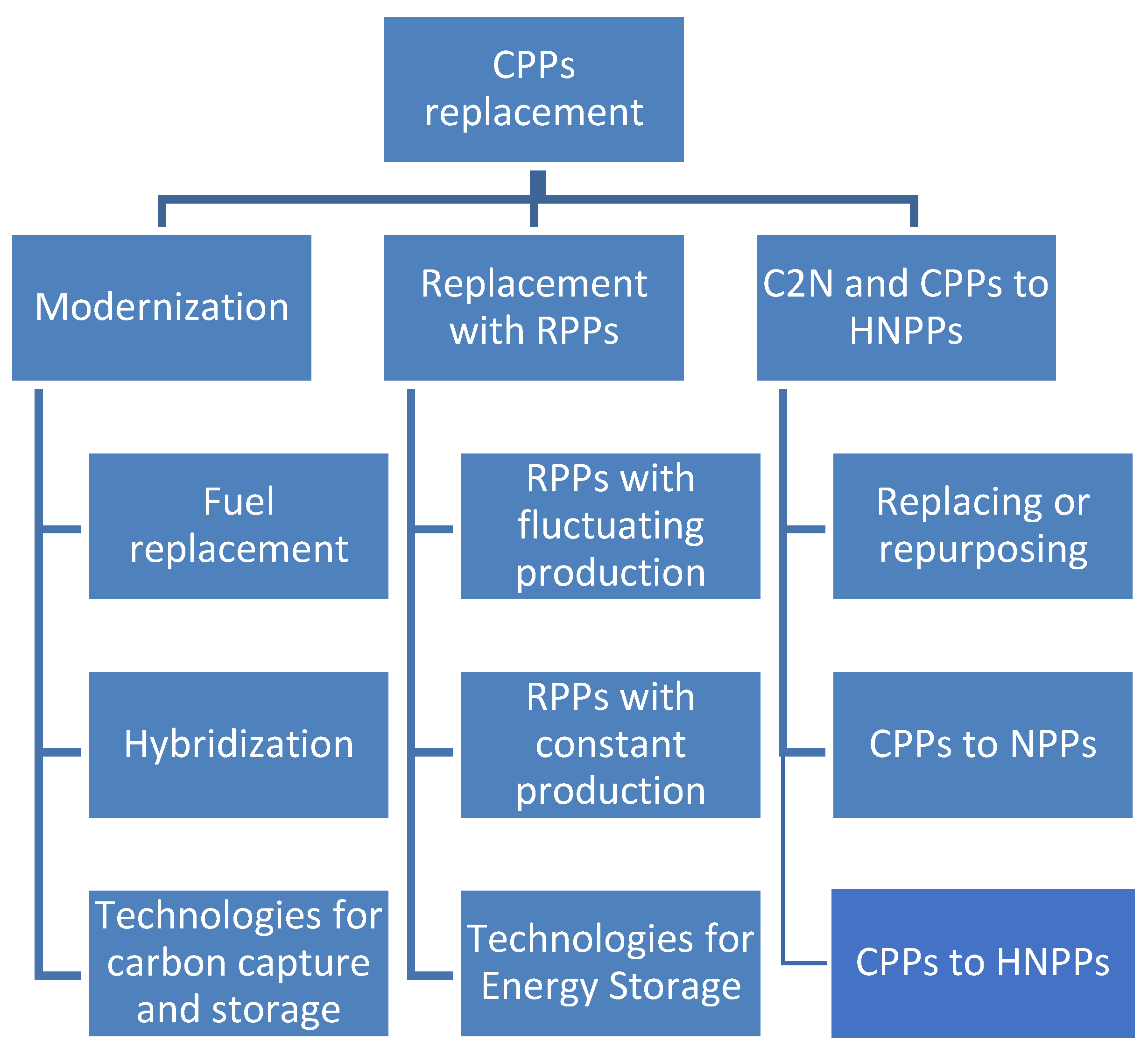
Figure 2.
Methodology for simulation and evaluation of the studied modified power plants.
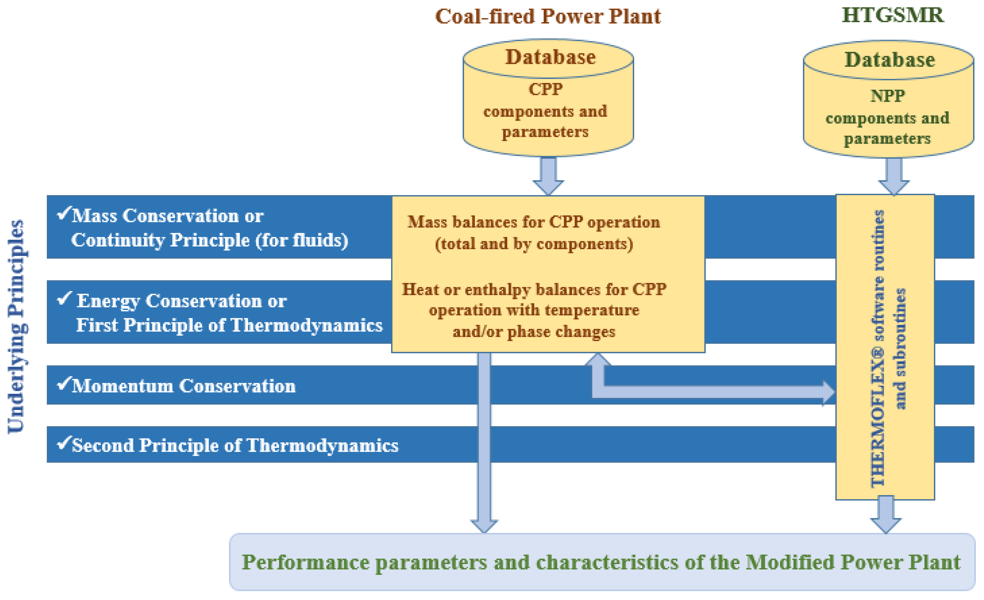
Figure 3.
Base model (Model 0) of CPP with the referent Steam Turbine.
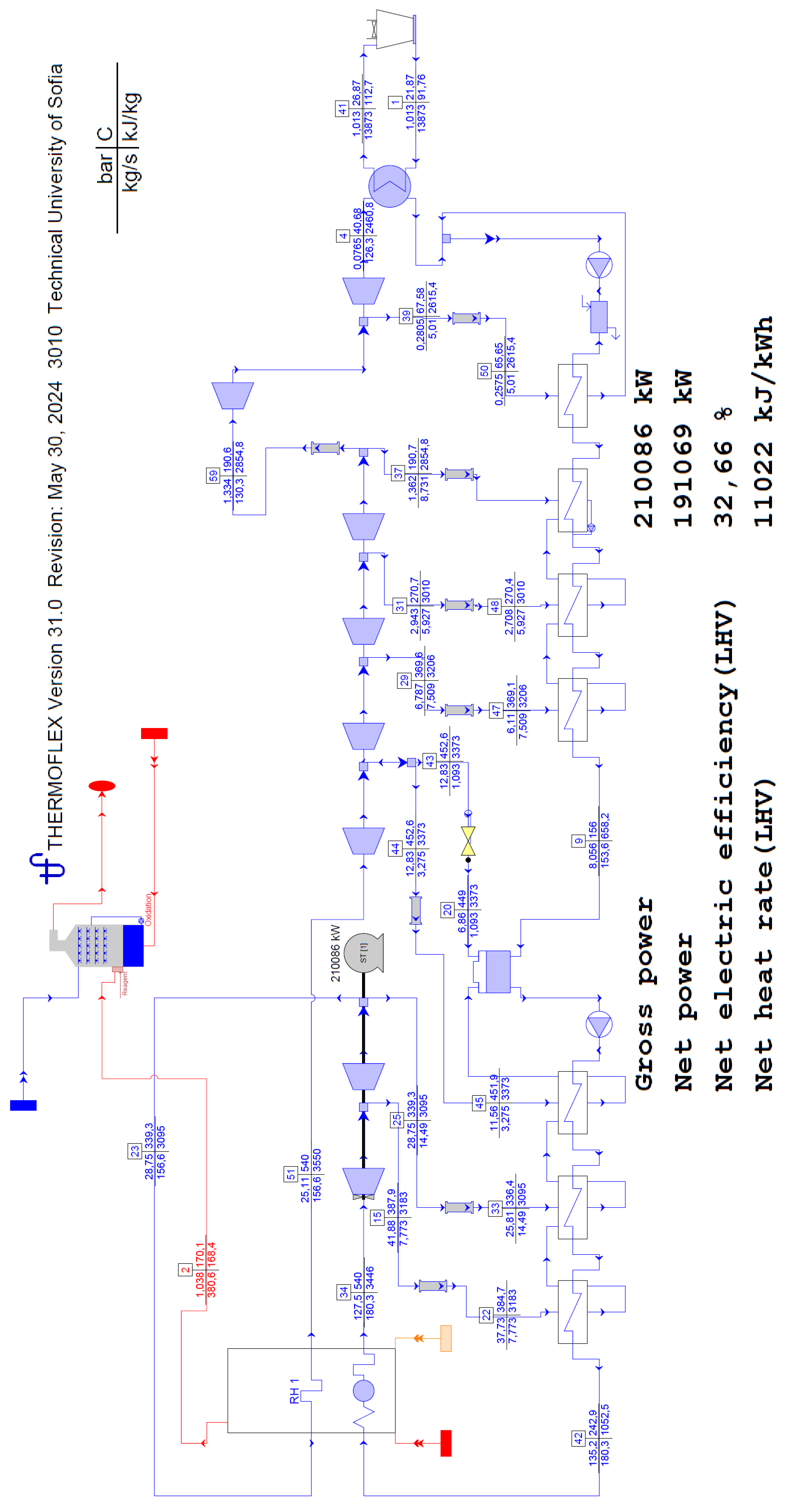
Figure 4.
Model 1: Configuration with elimination of one high-pressure FWH.
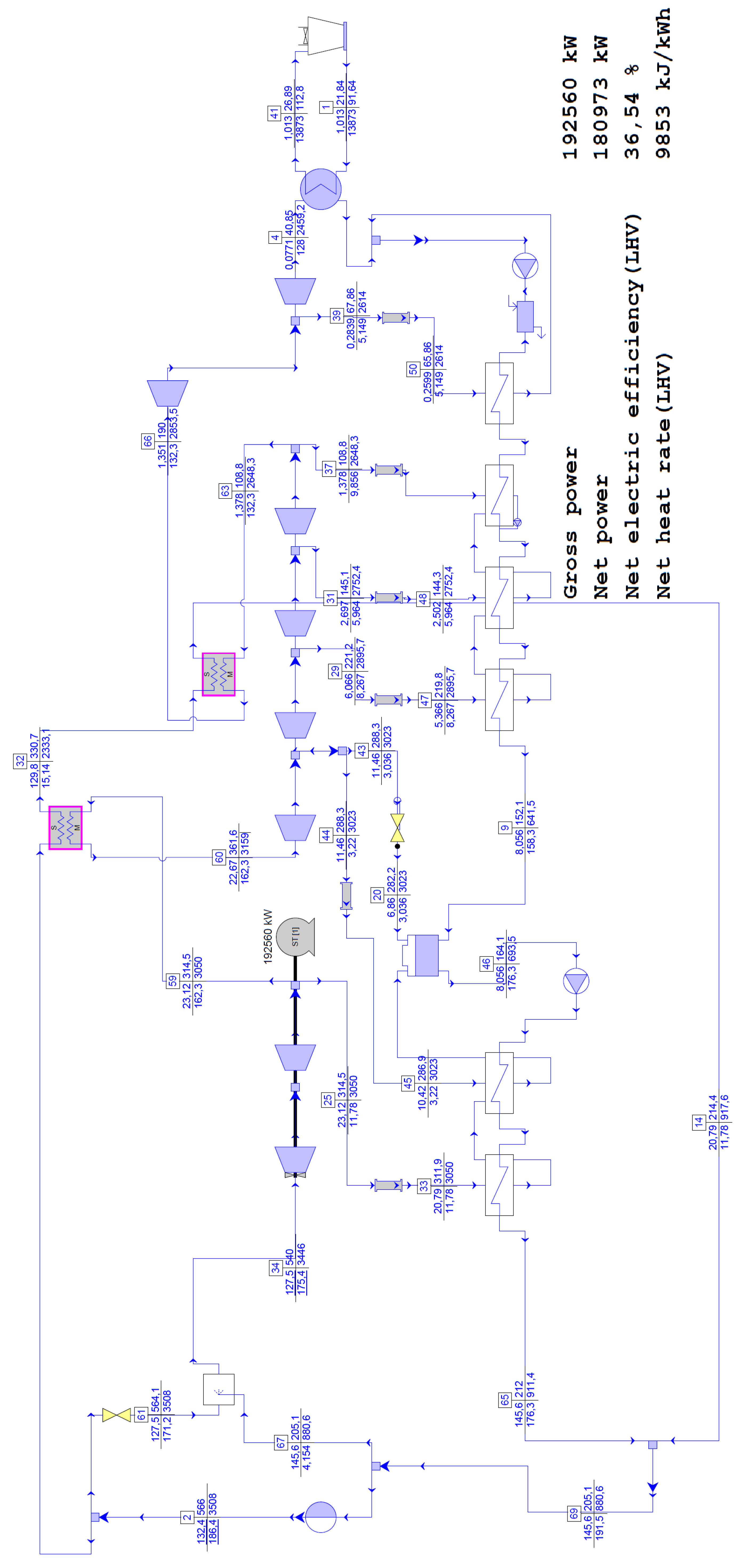
Figure 5.
Model 2: Configuration with elimination of two high-pressure FWHs.
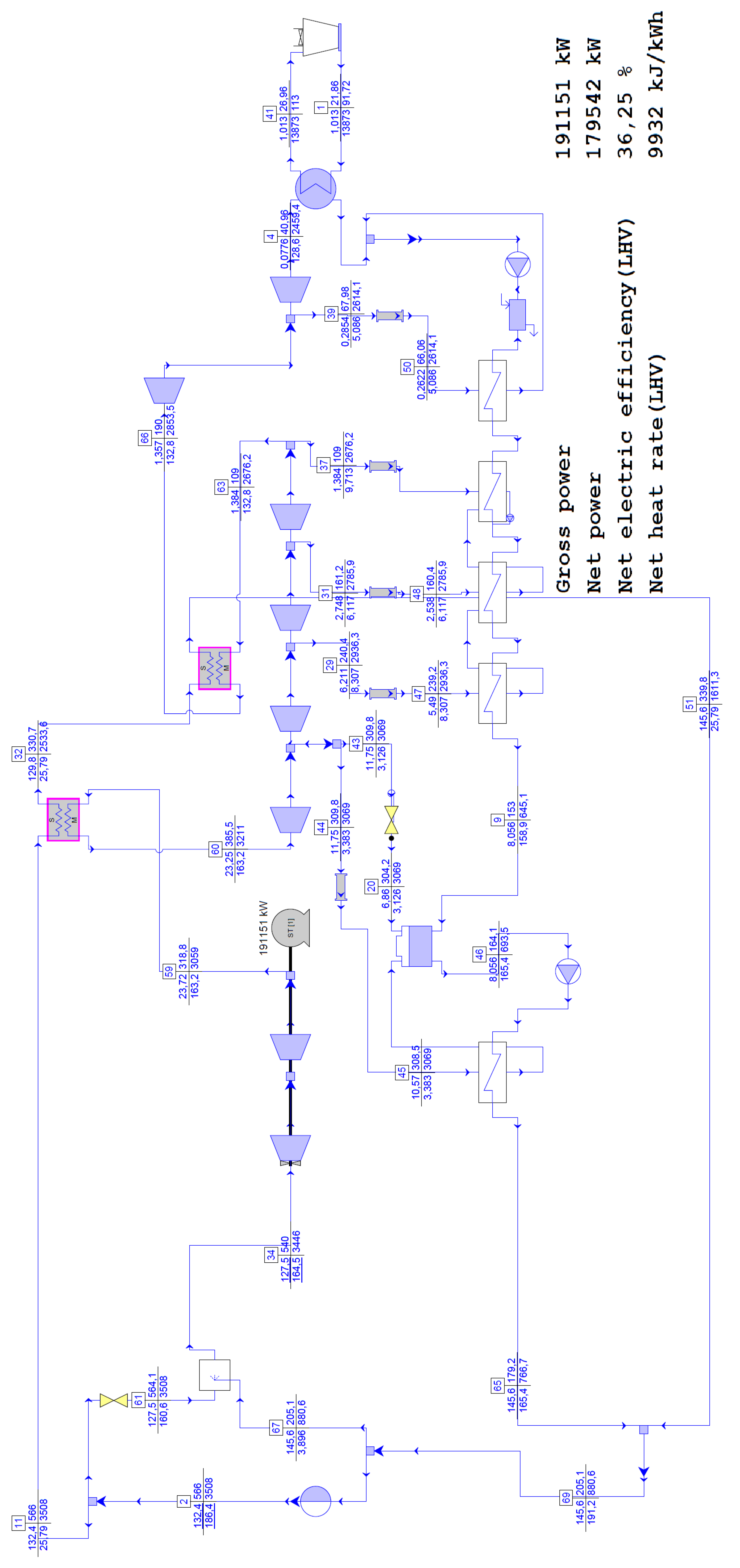
Figure 6.
Model 3: Configuration with elimination of all three high-pressure FWHs.
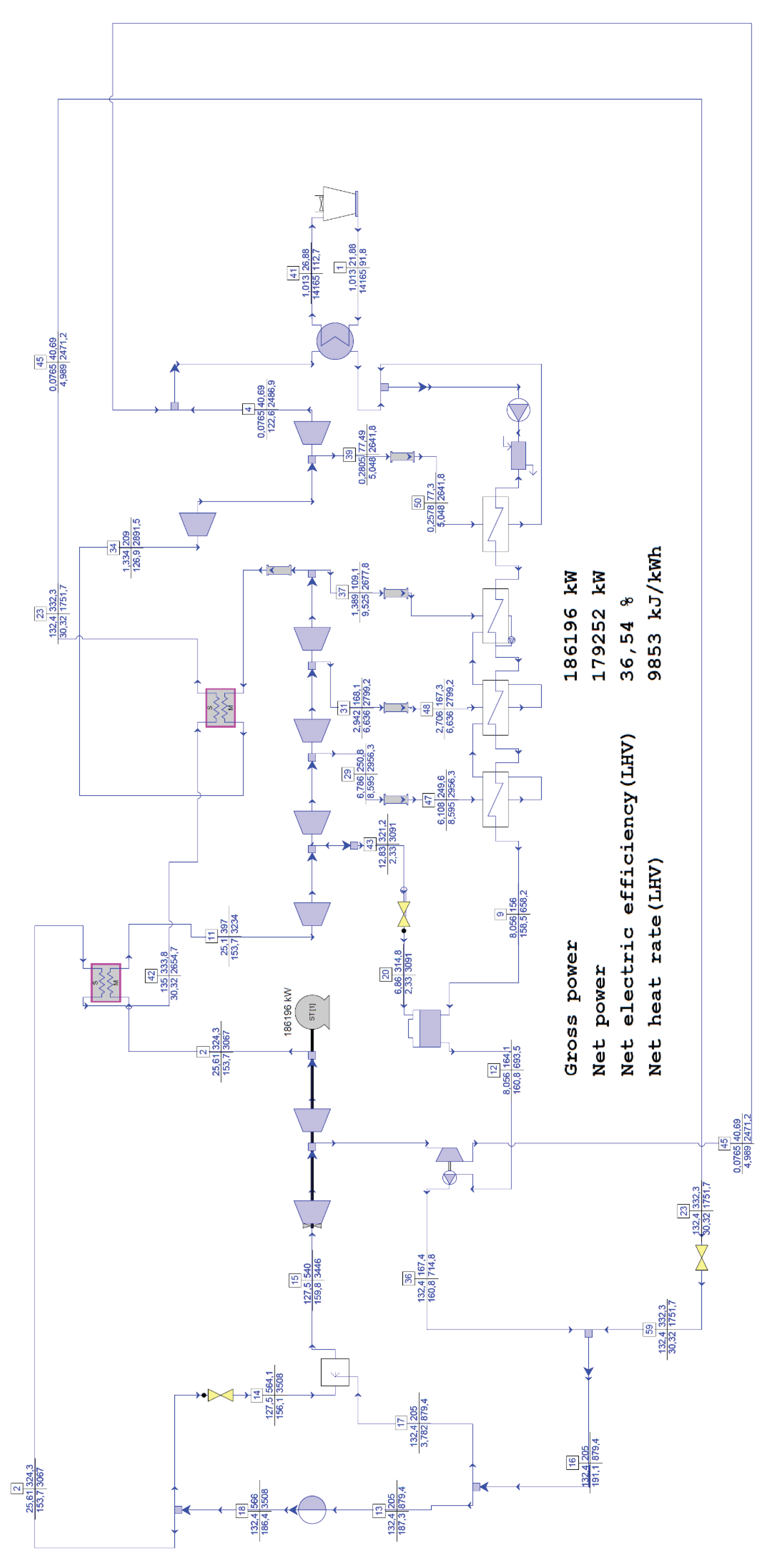

Table 1.
Parameters of the available SMRs important for C2N [27,28,29,30,31,32,33,34,35,36,37,38,39,40,41,42,43,44,45].
| Model | Layout | Thermal Power, MW | ST Inlet Temperature, °C | ST Inlet Pressure, MPa | ST Inlet Flow, kg/s | Feedwater Temperature at SG1 inlet, °C |
|---|---|---|---|---|---|---|
| HTR-PM | 2-Circle | 2x250 | 566 | 13.24 | 186.39 | 205 |
| BREST-300 | 2-Circle | 700 | 505 | 17 | >416.7 | 340 |
| CAREM-25 | Integral | 100 | 290 | 4.7 | 48 | 200 |
| VOYGR | Integral | 250 | 343 | 3.3 | — | 93 |
| SMART | Integral | 330 | 296.4 | 5.2 | 160.8 | 200 |
| UK SMR | 2-Circle | 1358 | 292 | 7.6 | — | — |
| SMR-300 | 2-Circle | 1050 | — | 6.2 | — | — |
| CFR-600 | 3-Circle | 1500 | 480 | 14 | — | — |
| ACP-100 | Integral | 385 | >290 | 4.6 | 155.56 | 105 |
| KLT-40S | Integral | 2x150 | 290 | 3.82 | 66.67 | — |
| RITM-200N | Integral | 2x190 | 295 | 3.83 | 84.72 | 170 |
| RITM-200S | Integral | 2x198 | — | 3.83 | 84.72 | 150 |
| Natrium | 3-Circle | 840 | — | — | — | — |
| Xe-100 | 2-Circle | 200 | 565 | 16.5 | 76.8 | 208 |
1 SG – Steam generator.
| Parameters | Units | Values |
| Thermal capacity | MW | 2x250 |
| Electrical gross capacity | MW | 211 |
| Reactor operating pressure | MPa | 7 |
| Core coolant inlet temperature | °С | 250 |
| Core coolant outlet temperature | °С | 750 |
| Primary coolant flow rate | kg/s | 2x96 |
| Plant design life | years | 40 |
| Fuel cycle length | days | 1057 |
| HPC turbine inlet pressure | MPa | 13.24 |
| HPC turbine inlet temperature | °С | 566 |
| Working medium flow rate at nominal parameters | kg/s | 186.4 |
| Steam generator feed water temperature | °С | 205 |
| Net power plant efficiency | % | 40 |
Table 3.
Parameters of the referent Steam turbine island [49].
Table 3.
Parameters of the referent Steam turbine island [49].
| Parameter | Units | Value |
| Electrical gross capacity | MW | 210 |
| HPC turbine inlet steam pressure | MPa | 12.75 |
| HPC turbine inlet steam temperature | °С | 540 |
| Working medium flow rate at nominal parameters | kg/s | 180.28 |
| Steam generator feed water temperature, | °С | 243 |
| Steam generator feed water pressure | MPa | 13.52 |
| Number of casings | - | 3 |
| Number of stages in HPC | - | 12 |
| Number of stages in MPC | - | 11 |
| Number of stages in LPC | - | 2х4 |
| Number of steam bleedings | - | 7 |
| Number of feed water heaters | - | 3 |
| Number of condensate water heaters | - | 4 |
| Number of deaerators | - | 1 |
| LPC turbine outlet steam temperature | °С | 40.5 |
| LPC turbine outlet steam pressure | kPa | 7.65 |
Table 4.
Comparison of Model 0 parameters with the real data.
| Parameters | Model 0 | Real | Difference,% |
| Electrical gross power, MW | 210.086 | 210 | 0.041 |
| HPC turbine inlet steam temperature, °С | 540 | 540 | 0 |
| HPC turbine inlet steam pressure, MPa | 12.75 | 12.75 | 0 |
| Working medium flow rate at nominal parameters, kg/s | 180.28 | 179.83 | 0.25 |
| MPC turbine inlet steam temperature, °С | 540 | 540 | 0 |
| MPC turbine inlet steam pressure, MPa | 2.511 | 2.5 | 0.44 |
| MPC inlet steam flow rate at nominal parameters, kg/s | 156.6 | 155.08 | 0.98 |
| LPC turbine inlet steam temperature, °С | 190.6 | 190 | 0.32 |
| LPC turbine inlet steam pressure, MPa | 0.1334 | 0.1334 | 0 |
| LPC inlet steam flow rate at nominal parameters, kg/s | 130.3 | 129.28 | 0.79 |
| LPC turbine outlet steam temperature, °С | 40.68 | 40.5 | 0.44 |
| LPC turbine outlet steam pressure, kPa | 7.65 | 7.65 | 0 |
| LPC turbine outlet steam quality, % | 95.3 | 95.3 | 0 |
| Steam generator feed water temperature, °С | 242.9 | 243 | 0.04 |
| Steam generator feed water pressure, MPa | 13.52 | 13.52 | 0 |
| Steam temperature of the 1st bleeding, °С | 387.9 | 388 | 0.026 |
| Steam pressure of the 1st bleeding, MPa | 4.187 | 4.188 | 0.024 |
| Steam temperature of the 2nd bleeding, °С | 339.3 | 339 | 0.09 |
| Steam pressure of the 2nd bleeding, MPa | 2.875 | 2.873 | 0.07 |
| Steam temperature of the 3rd bleeding, °С | 452.6 | 452 | 0.13 |
| Steam pressure of the 3rd bleeding, MPa | 1.283 | 1.283 | 0 |
| Steam temperature of the 4th bleeding, °С | 369.6 | 369 | 0.16 |
| Steam pressure of the 4th bleeding, MPa | 0.6787 | 0.6786 | 0.015 |
| Steam temperature of the 5th bleeding, °С | 270.7 | 270 | 0.26 |
| Steam pressure of the 5th bleeding, MPa | 0.2943 | 0.2942 | 0.034 |
| Steam temperature of the 6th bleeding, °С | 190.7 | 190 | 0.37 |
| Steam pressure of the 6th bleeding, MPa | 0.1362 | 0.1334 | 2.1 |
| Steam temperature of the 7th bleeding, °С | 67.58 | 67.556 | 0.336 |
| Steam pressure of the 7th bleeding, MPa | 0.02805 | 0.02805 | 0 |
Table 5.
Rough validation of Model 0 in lower power modes.
| Fresh steam flow rate, kg/s | Model 0 Power, MW | Real ST Power, MW |
| 170 | 200.105 | 200 |
| 145.8 | 175.154 | 175 |
| 123.1 | 150.386 | 150 |
| 82.5 | 103.943 | 100 |
Table 6.
Key parameters of the three evaluated C2N models.
| Parameters | Model 0 | Model 1 | Model 2 | Model 3 |
| Electrical gross power, MW | 210.086 | 192.560 | 191.151 | 186.191 |
| Electrical net power, MW | 191.069 | 180.973 | 179.542 | 179.252 |
| Electrical net efficiency, % | 32.66 | 36.54 | 36.25 | 36.54 |
| HPC turbine inlet steam temperature, °C | 540 | 540 | 540 | 540 |
| HPC turbine inlet steam pressure, MPa | 12.75 | 12.75 | 12.75 | 12.75 |
| Working medium flow rate at nominal parameters, kg/s | 180.28 | 175.4 | 164.5 | 159.8 |
| MPC turbine inlet steam temperature, °C | 540 | 361.6 | 385.5 | 397 |
| MPC turbine inlet steam pressure, MPa | 2.511 | 2.267 | 2.325 | 2.51 |
| MPC inlet steam flow rate at nominal parameters, kg/s | 156.6 | 162.3 | 163.2 | 153.7 |
| LPC turbine inlet steam temperature, °C | 190.6 | 190 | 190 | 209 |
| LPC turbine inlet steam pressure, MPa | 0.1334 | 0.1351 | 0.1357 | 0.1334 |
| LPC inlet steam flow rate at nominal parameters, kg/s | 130.3 | 132.3 | 132.8 | 126.9 |
| Steam generator feed water temperature, °C | 243 | 205.1 | 205.1 | 205 |
| Enthalpy drop of 1st group of stages, kJ/kg | 262.26 | 279.63 | 284.16 | 262.27 |
| Enthalpy drop of 2nd group of stages, kJ/kg | 88.48 | 115.68 | 102.82 | 116.5 |
| Enthalpy drop of 3rd group of stages, kJ/kg | 177.66 | 136.3 | 142.46 | 142.78 |
| Enthalpy drop of 4th group of stages, kJ/kg | 167.06 | 126.92 | 132.38 | 134.57 |
| Enthalpy drop of 5th group of stages, kJ/kg | 195.45 | 143.32 | 150.4 | 157.07 |
| Enthalpy drop of 6th group of stages, kJ/kg | 155.3 | 104.12 | 109.75 | 121.35 |
| Enthalpy drop of 7th group of stages, kJ/kg | 239.38 | 239.53 | 239.37 | 249.73 |
| Enthalpy drop of 8th group of stages, kJ/kg | 154.6 | 154.79 | 154.76 | 154.84 |
Table 7.
Performance comparison of the three C2N models under reduced power modes.
| Parameters | Model 0 | Model 1 | Model 2 | Model 3 |
| Electrical net efficiency for 175 MW, % | 32.65 | 36.53 | 36.25 | 36.54 |
| HPC inlet steam flow rate at 175 MW, kg/s | 145.8 | 156.3 | 148.5 | 150.3 |
| Electrical net efficiency for 150 MW, % | 31.89 | 36.31 | 36.05 | 36.55 |
| HPC inlet steam flow rate at 150 MW, kg/s | 123.1 | 130.7 | 124.9 | 128.8 |
| Electrical net efficiency for 100 MW, % | 29.83 | 35.12 | 34.78 | 36.59 |
| HPC inlet steam flow rate at 100 MW, kg/s | 82.5 | 83.27 | 81.84 | 85.8 |
Disclaimer/Publisher’s Note: The statements, opinions and data contained in all publications are solely those of the individual author(s) and contributor(s) and not of MDPI and/or the editor(s). MDPI and/or the editor(s) disclaim responsibility for any injury to people or property resulting from any ideas, methods, instructions or products referred to in the content. |
© 2026 by the authors. Licensee MDPI, Basel, Switzerland. This article is an open access article distributed under the terms and conditions of the Creative Commons Attribution (CC BY) license (http://creativecommons.org/licenses/by/4.0/).
Copyright: This open access article is published under a Creative Commons CC BY 4.0 license, which permit the free download, distribution, and reuse, provided that the author and preprint are cited in any reuse.