

Submitted:
23 February 2026
Posted:
26 February 2026
You are already at the latest version
Abstract
This study integrates in-situ Quantitative Infrared Thermography (QIRT) and Building Energy Simulation (BES) to optimize the energy performance of an existing multi-story residential building in a temperate climate. QIRT was utilized to diagnose thermal anomalies at the interfaces of uninsulated walls, RC skeleton and fenestration junctions, revealing significant thermal bridging and air infiltration while enabling the calculation of the Temperature Index (TI) at critical interfaces. A key finding of the non-destructive diagnostic phase was the discrepancy between in-situ (UINSITU) and theoretical (UCALC) thermal transmittance values, providing an empirical baseline for subsequent optimi-zations. A multi-objective analysis was conducted using genetic algorithms to evaluate 192 retrofit combinations, involving three insulation materials at four thicknesses and 16 glazing types. The impacts on primary energy consumption, CO₂ emissions, and 30-year global costs (per EN 15459-1:2017) were quantified under the volatile economic conditions. Findings indicate that the energy-optimal solution reduces primary energy by 53% and CO₂ emissions by 51%, while the cost-optimal configuration reduces global costs by 52% relative to the reference case. The Pareto analysis reveals a robust convergence between financial and energy efficiency targets, proving that deep retrofitting is an economically imperative strategy for achieving national decarbonization goals and the 2053 net-zero vision.
Keywords:
quantitative infrared thermography (QIRT)
; building energy simulation (BES)
; cost-optimal retrofit
; thermal bridging
; in-situ U-value
; multi-objective optimization
; temperature index (TI)
; energy performance gap
; economic volatility
1. Introduction
In Türkiye, the residential sector stands as a critical pillar of energy consumption, trailing only industry and transportation [1]. Accounting for 21% of electricity use and 20% of total end-use energy, dwellings represent 9% of national carbon emissions [2]. With a building stock exceeding 10 million units and housing 24 million households [3], the decarbonization of existing residential structures is not merely a technical challenge but a national imperative for achieving the NZEB and 2053 net-zero vision [4]. Given that space heating constitutes approximately 48% of household energy demand [2], the building envelope remains the primary target for enhancing thermal resilience and energy efficiency.
The national energy policy landscape has evolved through a sequence of regulatory instruments, primarily anchored by the Thermal Insulation Requirements for Buildings (TS 825) [5,6], and the Building Energy Performance (BEP) Regulation [7,8]. The introduction of the Energy Performance Certificate (EPC) program via BEP-tr in 2010 marked a shift toward mandatory documentation and verification of efficiency [9].
Recent updates, particularly the 2024 revisions to TS 825, reflect an iterative policy approach aimed at tightening thermal bridging considerations and insulation standards [6]. In their study on Turkish residential buildings, Caglayan et al. [10] demonstrated that Genetic Algorithm (GA) based envelope optimization can achieve energy savings 20–25% below these standard regulatory limits. While these regulations provide a baseline for new constructions, their application to the complex, uninsulated existing stock remains a significant area of research.
While external thermal insulation is widely recognized for mitigating thermal bridging, preventing condensation, and enhancing indoor comfort, its effectiveness is highly sensitive to climate-specific variables and material synergies. Research consistently demonstrates that insulation thickness, glazing efficiency, and heating, ventilation, and air conditioning (HVAC) capacities are interdependent factors [11]. For instance, studies have shown that inadequate consideration of thermal bridges can lead to an 'energy performance gap' where actual savings deviate significantly from theoretical projections [12,13,14]. Therefore, achieving deep retrofits requires more than generic compliance; it demands a precise alignment of in-situ performance diagnostics with multi-objective optimization to ensure both energy efficiency and economic viability under current market dynamics [15].
In 2024, the national standard TS 825 underwent a significant revision, tightening the recommended U-values, insulation thicknesses, and glazing selection criteria to align with modern efficiency targets [6]. However, as Aydin and Biyikoglu [16] emphasized through life cycle cost analysis for Turkey, earlier standards often fell short of economic optimums; by accounting for both heating and cooling loads, energy savings can be further increased by up to 21.5% beyond these regulatory limits. The evolutionary trajectory of these standards—comparing the reference U-values for the years 2008 and 2024—illustrates an increasingly rigorous regulatory environment for both new constructions and retrofitting projects in temperate-humid climates (Table 1).
Global energy and environmental policies have heightened the urgency of reducing the life-cycle energy impacts of the built environment, positioning the building envelope as the primary target for intervention since it fundamentally dictates space-conditioning demand. In accordance with the European Union (EU) Construction Products Regulation (CPR) [17] and the latest Energy Performance of Buildings Directive (EPBD 2024 recast) [18], building components are required to maintain high-performance standards —moving towards zero-emission targets—over an economically reasonable service life. This performance is largely governed by the envelope’s hygrothermal behavior, which not only shapes long-term energy efficiency and durability but also directly impacts thermal comfort and indoor air quality through its influence on surface temperatures and moisture regulation.
Dampness within the building envelope acts as a primary catalyst for thermal degradation. Persistent moisture—originating from construction residues, wind-driven rain, or interstitial condensation—triggers a cascade of chemical and physical deterioration that undermines structural durability and indoor air quality [19,20]. Consequently, the building envelope must fulfill a complex set of hygrothermal objectives: controlling water ingress, minimizing seasonal heat transfer, and eliminating thermal bridges. Thermal bridges, particularly those arising from the RC structural frame (beams, columns, floor slabs) and geometric junctions, create localized paths of high thermal conductivity. These anomalies not only elevate the effective U-value but also lower interior surface temperatures, significantly increasing the risk of mold growth and material decay [21]. Field audits by Tabet Aoul et al. [22] underscore that even in modern constructions, significant energy loss occurs due to such recurring defects as insulation discontinuity, which directly compromises occupant health and energy costs.
Infrared thermography (IRT) has established itself as a robust non-destructive tool for evaluating the hygrothermal performance of building envelopes. The theoretical reliability of IRT lies in its ability to relate surface temperature gradients to subsurface structures via passive or active methods [23]. By visualizing subsurface thermal failures that result in substantial heat loss, it enables the precise diagnosis of diverse defects, ranging from structural thermal bridges and air leakage to water ingress and interstitial condensation. Following Herschel’s early-19th-century discovery of the infrared (IR) spectrum, the technology transitioned from basic surface temperature mapping in the 1960s to today’s sophisticated Quantitative Infrared Thermography (QIRT). The process involves measuring IR radiation emitted by a surface—a parameter directly correlated with its absolute temperature—captured by micro-detectors and converted into pixelated thermograms in false color or grayscale. Each pixel within these thermograms is mapped to a specific temperature value, enabling the generation of precise line and area profiles. This level of granularity facilitates quantitative diagnostics of diverse thermal issues, ranging from missing insulation and structural thermal bridges to imbalanced HVAC operations [24,25]. When the internal structure of the building envelope is unknown, QIRT remains a viable option for measuring actual thermal bridging performance by correlating surface temperatures with dynamic heat transfer coefficients [26].
Earlier foundational work has established IRT as a versatile tool for building envelope diagnostics. Balaras and Argiriou [27] provided a foundational overview, identifying IRT’s potential for non-destructive assessment of moisture accumulation, air leakage, and thermal bridges. However, the accuracy of such assessments is heavily dependent on measurement conditions. This sensitivity was explored by Barreira and Freitas [28], who demonstrated the influence of emissivity, reflectivity, and wetting–drying cycles on thermographic reliability through laboratory and in-situ work, while Avdelidis and Moropoulou [29] further characterized material-specific emissivity across various surface states. To bridge the gap between measured and theoretical values, integrating high-resolution thermal imaging into building energy models has been shown to drastically reduce simulation errors [30].
To overcome the inherent limitations of single-sensor inspections, researchers have increasingly integrated multimodal and thermophysical approaches into building diagnostics. For instance, Meola et al. [31] successfully combined IRT with ultrasonics and geophysics to detect structural defects in masonry specimens and applied in-situ IRT to detect tile detachment, while Li et al. [32] elucidated the thermophysics of facade defects through lab-calibrated specimens and rainy-period field tests. Their findings demonstrated that moisture-laden areas exhibit lower surface temperatures due to evaporative cooling, whereas debonded patches appear as relatively warmer zones due to the increased thermal resistance of the entrapped air layers compared to sound structural regions. A recent study focusing on educational buildings in Türkiye further highlighted the thermal advantages of specific envelope materials over standard systems when evaluated through such in-situ IRT and thermal simulations [33].
Advancements have also been achieved in the quantification of thermal defects. Choi et al. [34] developed a quantitative facade evaluation methodology that correlates thermal imagery with heat-flow models, validating a diagnostic index based on the temperature difference ratios between defective and intact wall sections. Complementing this quantitative approach, Ribaric et al. [35] advanced a knowledge-based system that fuses co-registered IR and visual images. By transforming these fused datasets into diagnostic histograms via a dedicated graphical user interface, their work facilitates the automated identification of facade insulation anomalies.
The focus of IRT research has recently shifted towards high-fidelity digital integration and automated analysis. Adamus and Pomada [36] demonstrated the effectiveness of field-based thermography in isolating complex thermal bridges at window-to-wall interfaces. More recently, Rojas-Colmenares [37] introduced advanced digital twin workflows that encompass photogrammetry, Building Information Modelling (BIM), and thermography for comprehensive energy assessments. In parallel, integrating BIM, IRT, and heat flux sensors offers a practical framework for high-accuracy energy modeling even under real-world data scarcity [38]. The integration of Artificial Intelligence (AI) has also become a frontier; Abdulridha et al. [39] highlighted the effectiveness of convolutional neural networks in automating the detection of thermal anomalies in concrete structures, which significantly reduces manual inspection time and enhances diagnostic precision.
Furthermore, the role of multi-objective optimization has evolved; Wang et al. [40] highlighted how energy consumption prediction methods can be coupled with diagnostic data to optimize envelope retrofits under varying climatic conditions. To achieve long-term resilience, researchers now utilize advanced algorithms to identify optimal envelope configurations that balance immediate energy savings with climate considerations [11,41].
Despite these advancements, a significant methodological fragmentation remains in the literature; most research focuses either on qualitative defect detection or isolated, theoretically-driven simulation models. A critical gap persists in the seamless integration of in-situ IRT as the direct empirical engine for multi-objective optimization—particularly for existing residential stock where the discrepancy between as-built conditions and design specifications is most pronounced. Decision support tools are essential for aligning sustainability goals with technical outcomes throughout this process, particularly in building diagnosis and performance estimation [42]. This demand for efficiency necessitates a synergy where field-based diagnostics inform, rather than just follow, simulation-based analyses. Recent systematic reviews by Shan and Junghans [43] indicate that approximately 88% of building performance optimization studies focus on residential and office sectors, emphasizing the critical role of evolutionary algorithms in resolving these trade-offs between demand, cost, and comfort.
Among various optimization techniques, GAs remain the most widely adopted for building retrofits due to their computational efficiency [15,43]. A comprehensive bibliometric analysis by Li et al. [44] confirms that the integration of GAs with simulation platforms like EnergyPlus has been the dominant strategy over the last two decades. To address the methodological challenges of identifying optimal retrofit actions, Asadi et al. [45] proved that hybrid models combining Artificial Neural Networks (ANN) with GAs are highly effective in assessing the trade-offs between energy savings and retrofit costs. Furthermore, Al-Saadi and Al-Jabri [46] highlighted the importance of comparing cost-optimal designs with regional building codes to identify the most effective insulation and glazing types.
This study introduces an integrative framework that couples QIRT with BES to optimize deep retrofit strategies. The methodology is applied to a multi-story residential building in Istanbul’s temperate-humid climate, serving as a representative case for the uninsulated existing building stock. The research objective is twofold. First, facade inspections were conducted using QIRT to empirically assess the in-situ performance of uninsulated cavity and load-bearing walls. This diagnostic phase identifies systemic thermal failures and structural bridges, quantifying the discrepancy between as-is and theoretical thermal resistance through U-values and Temperature Indices (TI). Second, these empirical findings were used to establish a more representative baseline for the BES model, ensuring the retrofit analysis reflects the specific thermal characteristics of the existing envelope. Under this framework, a total of 192 scenarios—comprising twelve insulation thicknesses and sixteen glazing types—were analyzed. The study evaluates how these interventions reduce energy demand and carbon emissions, while a multi-objective optimization identifies the cost-optimal configurations. By balancing 30-year global costs with energy savings, this approach provides a resilient roadmap for energy efficiency, which is critical in volatile economic landscapes, where high inflation and fluctuating energy prices necessitate risk-averse investment decisions.
2. Materials and Methods
The methodological framework of this study integrates non-destructive diagnostics with simulation-based optimization to evaluate building retrofit strategies. As illustrated in Figure 1, the research focuses on combining in-situ QIRT with a dynamic BES environment. The workflow provides an overview of this integrated approach, detailing the data acquisition, processing, and multi-objective optimization stages.
The proposed framework utilizes a feedback loop where field-based empirical data refines the building energy model (digital twin), ensuring a high-fidelity baseline. This refined model enables the evaluation of retrofit combinations—focusing on external wall insulation and glazing upgrades—to identify energy-efficient and cost-optimal pathways for the residential case study.
2.1 Residential Retrofit Case Study
The selected case study represents a typical mid-2000s residential development in Istanbul, characterized by its humid-temperate climate. To establish a representative digital twin as outlined in the methodological framework (Fig. 1), the architectural geometry and material thermophysical properties were surveyed as primary inputs. The reinforce concrete (RC) complex comprises ten apartment blocks completed in 2007. Reflecting the post-1999 Marmara earthquake construction standards, the buildings were designed in compliance with the 2005 Earthquake Regulations utilizing a raft-general foundation system [47]. The case building is a six-story block consisting of a basement, a ground floor, and five upper floors. Each floor contains two independent flats (approx. 165 m² each), featuring four bedrooms and a living room. Despite being equipped with acoustic insulation for internal floors, the building's envelope represents the era's standard uninsulated RC characteristics. In terms of building systems, each dwelling is naturally ventilated and equipped with an individual gas boiler and split air-conditioning units, operated according to occupants’ thermal comfort preferences. The case building is was selected primarily due to the significant thermal abnormalities detected during preliminary inspections. The spatial layout and the current state of the building are illustrated in Figure 2, which presents the site plan of the residential complex (Fig. 2a) and the south-east façade of the investigated block (Fig. 2b).
The external infill walls were constructed using locally produced pumice aggregate concrete blocks (PACBs). These 19-cm-thick blocks feature tongue-and-groove edges and three rows of hollows, bonded with approximately 15 mm of cement bedding mortar. The interior is finished with a gypsum-based plaster, while the exterior features a cement-based render with either a silicone-based paint or ceramic tiles as the final coating. No thermal insulation was applied to either the infill walls or the RC elements. As shown in the plan detail in Figure 3, the interface between the masonry infill, the RC structural frame, and the fenestration was specifically examined, as these junctions represent the primary locations for potential thermal bridges.
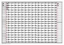
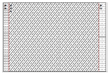
The theoretical performance of the building elements is determined using standard heat-transfer calculations, with thermal conductivity values (λ) assigned to each material layer in accordance with TS 825 [5,6], TS EN 1745 [48], and TS EN ISO 6946 [49]. Table 2 presents the cross-sections of the PACB infill and the RC structural elements of the reference building. It also details the theoretically-calculated thermal transmittance values (UCALC) calculated calculated using Formula 1, following the thermal Insulation requirements for buildings [5,51].
Where;
- Rsi and Rse are heat transfer coefficients of the internal and external surfaces, respectively (W/m2·K);
- d is the thickness of each material layer (m);
- λ is the thermal conductivity of each layer (W/m·K).
As presented in Table 2, the thermal transmittance of non-insulated RC elements is nearly four times higher than that of non-insulated PACBs walls. Furthermore, all UCALC values significantly exceed the 0.40 W/m²·K threshold —the thermal transmittance limit for energy-efficient wall component in the 3rd degree-day region according to the updated TS 825 standard [6].
2.2. IR Thermography Analysis
Interpreting building thermography is highly sensitive to three factor groups: building characteristics (surface emissivity, absorptance, moisture content, roughness), environmental conditions (indoor–outdoor temperature/pressure differences, solar radiation, wind, precipitation, relative humidity), and equipment setup (camera resolution, viewing angle, distance, acquisition settings). Surface contamination and wetting can alter apparent emissivity, while sun-exposed façades store heat that dissipates over time based on thermal mass and temperature gradients (ΔT), potentially masking defects. To minimize transient and reflective effects, surveys are ideally conducted at night or under heavy overcast conditions with a sufficient indoor–outdoor temperature difference, away from extraneous heat sources. This is critical because rain can distort readings through evaporative cooling, while moisture accumulation increases material thermal conductivity, which may artificially amplify anomalies under starker temperature gradients or with induced pressure differences [11,12,27].
The case study building’s envelope underwent in-situ examinations from both the interior and exterior. Surface temperatures of exterior wall components and junctions were recorded using a FLIR ThermoCAM E65 IR camera [50]. Simultaneously, microclimatic variables—indoor/outdoor dry-bulb temperature, relative humidity, and near-surface wind speed—were measured using handheld digital instruments (thermometer, hygrometer, and anemometer). Camera-to-target distances were verified with a laser meter, and thermal images were captured from multiple angles using a constant surface emissivity for all scans.
The measurement conditions were aligned with ISO 9869-1:2014 [51] ensuring a stable temperature gradient. To minimize experimental uncertainty, periods with consistent temperature differentials were prioritized. Specifically, IR measurements were conducted during the winter season under near-steady-state conditions—early morning or after sunset—to eliminate the influence of direct solar radiation and precipitation. A minimum indoor-outdoor temperature difference of 5°C was maintained throughout the data collection. Thermograms were evaluated alongside floor plans, photographs, and supporting measurements to identify thermal anomalies. Detailed IR camera specifications are provided in Table 3 [50].
The actual thermal performance of the bulding envelope was determined using temperature data obtained via IRT. Based on the equations provided below (Eq. 2-4), in-situ measurements were conducted on both internal and external surfaces to derive the thermal transmittance values (UINSITU, W/m2·K) and temperature indices (TI, unitless) for the non-insulated PACB infill and RC structural elements. Following the methodology proposed by Fokaides and Kalogirou [52], internal surface measurements were used to establish a baseline, while the external heat balance—incorporating radiative and convective heat transfer—was calculated according to the refined models by Albatici and Tonelli [53] and Albatici et al. [54]. These in-situ results were subsequently compared with the theoretically calculated values (UCALC, W/m2·K) to evaluate the deviation between design-based assumptions and real-world performance.
Where:
- 5.67 is the constant dervied from Stefan-Boltzmann constant (σ = ∙;
- ε is the thermal emissivity of the surface (unitless), assumed to be 0.93 based on material characteristics;
- Tsi and Tso represent the in-situ internal and external surface temperatures (K), respectively;
- Tin and Tout are the indoor and outdoor ambient temperatures (K);
- v denotes the local wind velocity (m/s).
2.3. BES-based Energy Optimization Analysis
The BES-based optimization analysis aims to minimize the reference building’s primary energy consumption and identify cost-optimal energy-efficiency levels tailored for Istanbul’s temperate–humid climate zone. The core performance metrics include fluctuations in heating, cooling, and lighting energy use, alongside total annual primary energy consumption, operational carbon emissions, and global costs. To evaluate these parameters, a dynamic BES approach was employed, allowing for a high-fidelity comparison between the baseline and various retrofit scenarios.
The building energy model was developed using DesignBuilder v7.0, utilizing the EnergyPlus v9.4 engine for detailed dynamic simulations. To ensure environmental accuracy, the analysis integrates Typical Meteorological Year extended (TMYx) data via an Istanbul EPW (EnergyPlus Weather) file, spanning records from 2009 to 2023 [55]. This dataset provides a representative profile of the region’s temperate-humid climate, characterized by specific monthly variations in dry-bulb temperature, relative humidity, and solar radiation.
To ensure the simulation accurately reflects real-world performance, the BES model incorporates operational schedules and occupancy patterns derived from face-to-face interviews with the residents, along with realistic efficiency rates and the building's actual geometrical dimensions, including window-to-wall ratios (WWR). Key parameters—such as thermal setpoints for indoor environmental quality, HVAC and lighting system operating hours, efficiency and occupant-driven load profiles—are integrated to enhance the model's reliability. Crucially, the envelope’s thermal properties were defined using the UINSITU values derived from IRT analysis, bridging the gap between theoretical assumptions and as-built performance. The boundary conditions and specific parameter settings used for the reference scenario are summarized in Table 4.
The simulation follows specific temporal patterns to represent typical residential behavior. During the heating season, combi boilers scheduled to operate daily from 06:00 to 00:00, governed by indoor operative temperature setpoints. Conversely, the cooling schedules for multi-split air conditioners and the lighting system (active between 07:00 and 00:00) are dynamically adjusted based on room occupancy. As illustrated in Figure 4, the occupancy model utilizes a normalized hourly fraction to dictate both the internal heat gains and the operational frequency of the HVAC and lighting systems. This approach ensures that energy consumption is linked to real-time room usage across weekdays and weekends through a normalized occupancy fraction; where a value of 1 represents full-hour occupancy, 0.5 indicates a half-hour duration, and 0 denotes an unoccupied state. This temporal data ensures that the BES model accurately captures the stochastic nature of internal heat gains and energy demand.
Following the establishment of the reference energy profile, various retrofit measures were assessed through multi-objective optimization. Two key envelope variables—insulation thickness and glazing types—were evaluated, comprising 28 discrete options that yielded a total of 192 possible design combinations. To identify Pareto-optimal solutions, a Genetic Algorithm (GA) within DesignBuilder was employed. The optimization was conducted over a full annual cycle (8,760 hours), utilizing an initial population of 20, a convergence threshold of 10, and a maximum limit of 100 generations to ensure a robust search of the solution space.
End-use energy data from the optimization results were converted into primary energy consumption using national conversion factors: 1.0 for natural gas and 1.677 for electricity, while operational carbon emissions were quantified using emission factors of 0.234 kgCO2-eq/kWh and 0.478 kgCO2-eq/kWh, respectively, in accordance with national benchmarks reported by the Turkish Republic Ministry of Environment, Urbanization, and Climate Change [59]. These calculations were processed in Microsoft Excel, where the data were further analyzed to derive the final performance metrics and to generate the corresponding analytical charts.
2.3.1. Retrofit Scenarios and Design Variables
To identify the most effective strategies for reducing energy consumption and global costs, a series of retrofit scenarios were defined based on the most impactful envelope components. The optimization framework evaluates a total of 192 design combinations, systematically generated from 28 discrete options involving external wall insulation and glazing systems. These scenarios aim to explore the trade-offs between initial investment costs and long-term energy savings, ultimately determining the cost-optimal configurations for the temperate-humid climate. The specific technical properties and variations of these design parameters are detailed in the following sub-sections.
External Wall Insulation Scenarios
Various insulation materials and thicknesses were simulated to evaluate their impact on reducing transmission heat losses through the building envelope. Table 5 details the insulation configurations applied to external cavity walls, including their thermophysical properties and associated unit prices used in the cost-benefit analysis. To systematically improve the thermal performance beyond the regulatory limit (Uwall = 0.4 W/m²K) established for the 3rd degree-day region in the updated national insulation standard [6], solid-wall assemblies were analyzed by including various insulation materials such as Expanded Polystyrene (EPS), Extruded Polystyrene (XPS), and stone wool, along with their respective thicknesses (6 to 12 cm).
The initial investment costs —comprising material, labor, transportation, and applicable taxes—were sourced from the Construction and Installation Unit Prices published by the Ministry of Environment, Urbanization, and Climate Change [60], supplemented by current local market surveys. The service life expectancy of the insulation materials and glazing systems were determined in accordance with the ISO 15686-1 standard [61] to ensure accuracy in the long-term life-cycle cost analysis.
Glazing and Window System Scenarios
Variations in glazing systems were analyzed to evaluate their potential in balancing heating, cooling, and lighting energy demands while optimizing the global costs. Sixteen double-pane glazing configurations were developed by combining key design parameters: glazing types (low-e, solar low-e, and temperable solar low-e), pane thicknesses (4 mm or 6 mm), gap widths (12 mm or 16 mm), and cavity fillings (air or argon). For each configuration, critical thermo-physical and optical properties— specifically visible transmittance (Tvis), solar heat gain coefficient (SHGC), and thermal transmittance (U-value)—were integrated into the model. These scenarios were established based on the certified product catalogs of a prominent national glass manufacturer in Türkiye [58]. The technical specifications of the glazing retrofit options are summarized in Table 6.
2.4. Global Cost Analysis
The economic viability of the reference building and the proposed retrofit solutions is evaluated through a global cost analysis, conducted in accordance with the EN 15459–1 standard [62]. Given that the reference building is currently 20 years old and has an estimated total service life of 50 years, a 30-year calculation period is adopted, with 2025 established as the base year. The global cost incorporates the initial investment, annual running costs, replacement costs, and residual value, is calculated using Equation 4:
Where:
- Cg (τ) represents the global cost,
- Cinv represents initial investment costs,
- Cy (τ) denotes the yearly running costs (including energy and maintenance),
- Cr (τ) signifies replacement costs for components with shorter life cycles, and
- Vf,τ (j) represents the residual value for the combination of measures j at the end of the calculation period (τ).
The financial calculations account for the time value of money by discounting future expenditures to their present value, considering January 2025 as the reference starting point (Year 0) for all projections. Based on the Federal Reserve Economic Data (FRED) and Central Bank of the Republic of Türkiye (CBRT) statistics spanning 2016–2025 [63,64,65,66], the model utilizes the average annual inflation rate (Ri) and market interest rate (R) to derive the nominal discount rate (RATdisc), ensuring the financial model accounts for the specific macroeconomic volatility of the region. The negative real interest rate reflects the high-inflation environment where the annual consumer price increase outpaces market interest rates.
To ensure international comparability and mitigate the volatility of domestic inflation, all financial metrics, including initial investment costs (CInv), were fixed to January 2025 prices in TRY and subsequently converted to USD [67]. Annual energy costs were computed by multiplying these base year unit prices [68,69] by the corresponding end-use energy values obtained from the simulations.
A specialized discounting approach was adopted to integrate energy-specific escalation rates for electricity (ee) and natural gas (eg). These rates were derived separately because residential energy price trends over the last decade have diverged from general consumer price inflation. To reflect this divergence, historical price trends from the Energy Market Regulatory Authority (EMRA) [68] and the regional natural gas distributer (İGDAŞ) [69] were cross-referenced with inflation data from the CBRT [64]. Consequently, future energy expenditures were projected using these escalation factors before being discounted to their present value. Following the EN 15459-1 standard [62], the set of economic indicators, rates and unit prices utilized in the global cost analysis is summarized in Table 7.
3. Results and Discussion
3.1. IRT Assesment of Building Envelope
To assess the hygrothermal performance of the building envelope, a series of thermographic inspections were conducted using a holistic approach, progressing from the component to the façade scale. Periodic measurements were recorded across several apartment blocks within the same residential complex to derive thermal values, utilizing internal surface temperatures for indoor calculations and external parameters for outdoor assessments. However, this paper specifically focuses on the external envelope conditions of the thermally most critical apartment in Block B, which features a cantilevered first-floor configuration exposed to outdoor conditions from both the walls and the floor. The external wall system — comprising infill masonry (units, mortar, and surface finish), the RC structural frame (columns, beams, shear walls, and floor slabs), and window assemblies (frames, casements, glazing, sills, and sealants) — was analyzed systematically. Inspection points and critical junctions were documented and schematically illustrated on the floor plans and elevations in Table 8.
The in-situ thermal monitoring revealed thermal inefficiencies within the external envelope and identified problem zones of elevated heat loss, thereby elucidating both the spatial distribution and the probable causes of thermal anormalities. Surface temperature data from both reference and defect areas were used to compute the in-situ thermal transmittance (UINSITU) and temperature index (TI) of the building components. The thermograms were matched with photographs from a smartphone-based photogrammetric survey, and the identified thermal failures are summarized in Table 9 and discussed below, with particular emphasis on thermal bridges and warm air leakage on non-insulated external wall surfaces (I), RC structural frame (II), and fenestration interfaces (III).
The in-situ thermal analysis conducted across various building envelope sections reveals a significant divergence between standardized reference points and structural anomalies. Although the PACB fabric is designed to provide thermal resistance through its porous solid matrix and staggered hollow geometry, its field performance varies significantly. Reference wall sections (I-A) exhibited UINSITU values ranging from 1.15 to 2.71 W/m2K. These empirical results notably exceed the theoretical transmittance calculated for the masonry wall (UCALC = 0.896 W/m2K), indicating a substantial performance gap. This discrepancy suggests that real-world thermal efficiency is diminished by factors such as, material aging, workmanship inconsistencies, and moisture content.
A primary source of this discrepancy stems from the input data used for the thermal conductivity of PACBs in relevant standards. According to TS 825 [5], theoretical calculations should utilize thermal conductivities of materials in equilibrium with 80% relative humidity. However, standards also provide dry-state thermal conductivity values, which can be misleading; utilizing dry-state data in theoretical models leads to significant underestimations of heat loss, particularly for highly porous materials that are prone to moisture absorption. Furthermore, the high thermal conductivity inherent in the cement bedding mortar and cement rendering layers likely facilitates additional heat bypass, undermining the theoretical insulative properties of the masonry units.
Structural thermal bridges at beam-column junctions (II-A) and floor slab edges (II-B) reached critical UINSITU levels as high as 4.55 W/m2K, representing a localized heat flux increase of nearly 250% compared to the reference masonry. Due to the high thermal conductivity of RC and the extensive surface area of uninsulated exposed structural frame, a substantial decrease in thermal resistance was observed at RC components relative to the reference area (I-A) within the same thermograms. At these thermal failure zones, the increase in thermal transmittance indicates a severe compromise of the envelope's integrity. Notably, the discrepancy between UINSITU and UCALC for RC elements was relatively lower than that of the masonry sections. This suggests that while RC components act as high-conductivity pathways for energy dissipation, their in-situ performance aligns more closely with theoretical expectations for uninsulated concrete.
The thermal performance was further evaluated using the TI, which served as a primary diagnostic tool for assessing condensation risks. Experimental data indicated that several junction points fell critically below the 0.70 threshold in ISO 13788 [20], a value widely regarded as the safety limit for preventing surface mold growth. The most significant performance degradation was observed in internal measurements where surface condenstation risks were high; for instance, a reference point on the PACB wall (I-A) yielded a TI as low as 0.35 with a corresponding UINSITU value of 2.71 W/m2K. On the other hand, the thermal performance analysis revealed a critical paradox at the PACB wall-to-wall junction (I-B): despite a deceptively high TI of 0.82, the UINSITU value reached an extreme 6.34 W/m2K. This discrepancy arises because the low indoor temperature (17.2 °C) mathematically inflates the TI, even though the surface temperature (12.5°C) closely approximates the outdoor ambient conditions.
This performance failure is driven by a vicious cycle of moisture dynamics. The measured surface temperature of 9.7°C equilibrated with the calculated dew point (9.75°C), confirming the observed surface condensation. In this scenario, the ceramic tiles, acting as an impermeable surface finish, function as a water barrier that restricts the transmission of water vapor. This entrapment of moisture may lead not only to tile detachment through bond failure but also to deeper moisture penetration into the PACB fabric. Such saturation significantly increases the material's thermal conductivity (λ), leading to accelerated heat loss and a further decline in surface temperatures. Consequently, the persistent moisture accumulation and rising damp result in a fundamental failure of the building envelope, severely compromising both energy efficiency and occupant comfort. Such a low TI signifies that the internal surface temperature (Tsi) is almost equivalent to the outdoor ambient conditions (Tout) creating a high probability of interstitial condensation and long-term microbiological degradation of the building fabric.
Furthermore, the thermographic evidence identified distinct patterns of warm air leakage (III-A and III-B) that compound the overall energy inefficiency of the envelope. In these areas, the synergy between convective heat loss and conductive thermal bridging led to a precipitous drop in surface temperatures, exemplified by a Tsi of only 10.4°C despite an indoor temperature of 18.2°C. These anomalies, typically resulting from defective joinery seals or poor integration between the window/door frames and the masonry, necessitate a comprehensive retrofit strategy. The findings suggest that improving the energy rating of existing buildings requires not only the application of thermal insulation but also a rigorous focus on airtightness and the mitigation of geometric thermal bridges at the design and construction stages.
A critical performance gap was identified when comparing the building's current state to national benchmarks. All analysed wall types exhibit UINSITU values that significantly exceed the 0.60 W/m²·K threshold defined for energy-efficient wall components in TS 825 [5], and fall even further behind the more stringent 0.40 W/m²·K limit introduced in the revised TS T825 standard [6] for the 3rd degree-day region. This finding further corroborated by by theoretical UCALC values, highlights a non-compliance with modern energy regulations.
Consequently, even exterior wall surfaces that do not exhibit specific structural failures maintain temperatures notably higher than the ambient outdoor environment, signaling continuous heat dissipation from the interior. These IRT findings visually and numerically confirm that the current thermal resistance of the building envelope is insufficient to comply with local climatic requirements, updated national BEP regulations [8], and current thermal insulation standards [6].
To address these systemic deficiencies, it is necessary to evaluate the impact of holistic retrofit strategies. Accordingly, the following section explores BES-based optimization scenarios, focusing on the integration of continuous external thermal insulation and high-performance glazing improvements to restore the building’s thermal integrity and reduce energy consumption and operational carbon emissions.
3.2. BES Based Optimization Results
The analysis evaluates the energy and economic performance of various retrofit scenarios for the reference building between 2016 and 2025. By employing a 30-year life-cycle perspective in accordance with EN 15459-1 standard [62], the study identifies the most viable strategies for reducing annual primary energy consumption and global costs.
Figure 5 presents a scatter plot of various insulation and glazing combinations that outperform the reference building, specifically highlighting the energy-optimal (E1) and cost-optimal (C1) solutions. The x-axis represents the annual primary energy consumption, while the y-axis denotes the global cost, including initial investment, annual operation, and replacement costs for thermal insulation and glazing. The reference building is excluded from the focused scatter plot axes in Figure 5 to maintain visual clarity among the Pareto-optimal solutions, as its primary energy consumption and global cost significantly exceed the optimized range.
The Pareto analysis identifies a series of non-dominated solutions that significantly outperform the baseline, revealing a robust correlation between energy savings and global costs. The regression analysis indicates a strong linear relationship (R² = 0.7963), confirming that approximately 80% of the variance in global cost is explained by primary energy consumption. This statistically significant correlation demonstrates that as primary energy consumption decreases, total life-cycle costs follow a consistent downward trend. Furthermore, the model quantifies the economic impact of energy performance: each 1 kWh/m2·y increase in primary energy consumption is associated with a marginal global cost increase of approximately $7.97/m2 over the 30-year study period. Additionally, the fixed cost component of the regression model—representing initial investment, maintenance, and periodic repairs regardless of energy use—was calculated at $40.83/m2.
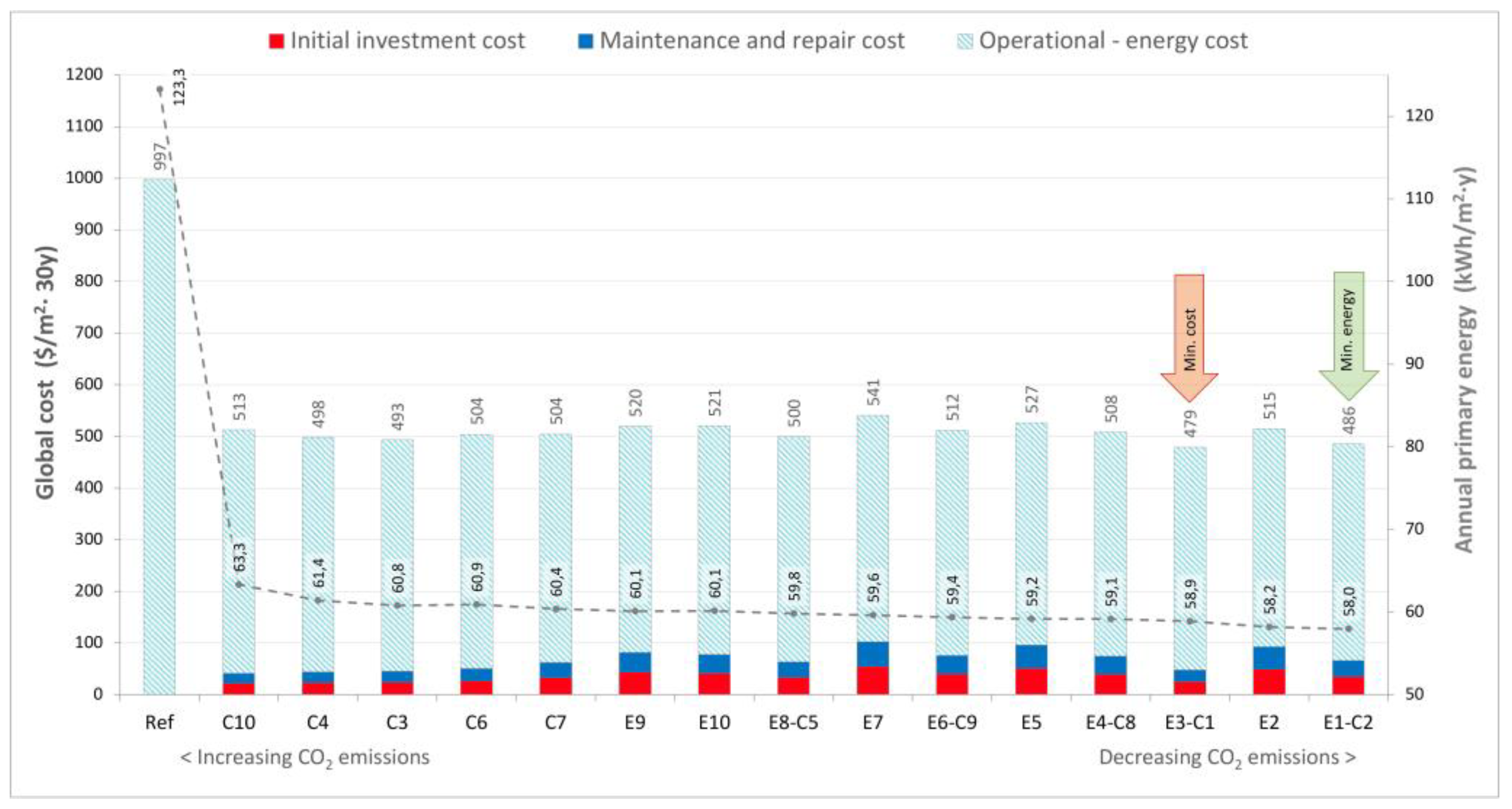
Following the trend observed in the regression, specific optimal points emerge as key strategic benchmarks. Figure 6 illustrates the Pareto-optimal frontier, where a convergence analysis focusing on the top 10 cost-optimal and the top 10 energy-optimal solutions reveals that these targets frequently coincide in high-performance envelope configurations. These solutions are further categorized into energy-oriented (E) configurations, prioritizing the minimization of annual primary energy consumption , and cost-oriented (C) options, focused on reducing life-cycle global costs. To emphasize environmental impact, the solutions are arranged from left to right in descending order of operational carbon emissions. Furthermore, Table 10 details the specific improvement rates achieved by these Pareto-optimal solutions across key performance metrics—including heating, cooling, lighting, operational carbon emissions, and global cost—using the reference building (Ref) for comparison.
The reference building exhibits an annual primary energy consumption of 123.3 kWh/m2·y, a total global cost of 997 $/m2, with an operational carbon footprint of 30.2 kgCO2-eq/m2·y. The results indicate that energy-oriented (E) configurations achieve a primary energy reduction ranging from 51% to 53%, while cost-optimal (C) solutions lower global expenditures by 49% to 52%.
A critical finding of this study is the identified convergence between these two objectives—where cost-optimal and energy-optimal points coincide. Among these, the best performing energy-oriented configuration, E1, lowers primary energy consupmtion to 58,0 kWh/m²·y with a corresponding 30-year global cost of 485,8 $/m². Simultaneously, the cost-optimal option, C1, maximizes long-term financial feasibility by reducing the global cost to 479.3 $/m², representing a 51.9% saving (58,9 kWh/m²·y) over the reference case.
The marginal difference between these two scenarios—only 0.9 kWh/m²·y in energy performance and 6.5 $/m² in global cost—highlights a significant convergence between environmental and financial objectives. This coinciding behavior indicates that high-performance energy targets are achievable without an exponential increase in global costs. The synergy suggests that the selected insulation and high-performance glazing strategies are highly effective in balancing financial feasibility with energy efficiency goals. Specifically, the transition from uninsulated walls to 12 cm insulation layers (EPS, XPS or stone wool), reducing Uwall to as low as 0.226 W/m²K, combined with argon-filled, low-e/solar low-e units (G2, G12) —which not only lower Uglazing from 2.4 to 1.1 W/m²K bu also strategically optimize solar gains (SHGC: 56–63%) and light transmittance (Tvis: 79%) —serves as the primary driver of this balance. This configuration manages the trade-off between heating and cooling energy without compromising daylight intake, as the selective glazing prevents the potential overheating risks typically associated with high insulation thicknesses in temperate humid climates.
Beyond energy and cost savings, the BES-based optimization analysis reveals a significant reduction in the building’s environmental footprint. The energy-oriented solution (E1) achieves an improvement of 15.4 kgCO₂-eq/m²·y, representing a 50.9% reduction in annual operational carbon emissions compared to the baseline. This brings the operational carbon footprint down from 30.24 to 14.85 kgCO₂-eq/m²·y.
4. Conclusions and Future Work
4.1. Insights from the IRT Survey
In this study, a QIRT survey was integrated to assess the thermal integrity of the building, providing an empirical foundation for the subsequent BES-based optimization. This diagnostic approach enabled the identification of significant thermal bridges and the validation of surface temperature distributions, particularly at critical interfaces of non-insulated external wall surfaces, the RC structural frame, and fenestration boundaries. The results suggest that IRT should be routinely employed in building inspections, as quantitative surface temperature analysis offers a reliable pathway for assessing real-world thermal conditions and refining the energy ratings of existing buildings.
A critical finding of the in-situ measurements is the discrepancy between predicted and actual thermal performance. The data indicate that the in-situ thermal transmittance (UINSITU) of non-insulated PACB walls is significantly higher than the theoretically calculated values (UCALC), confirming that the actual thermal resistivity is lower than expected. This performance gap is attributed to several factors inherent in aging building stocks, including material degradation over time, moisture content and workmanship inconsistencies. While UINSITU and UCALC values for the RC components were more closely aligned, the widespread structural thermal bridges at beam-column junctions and floor slab edges remain primary conduits for continuous heat dissipation in a non-insulated building envelope.
The calculation of the TI served as a diagnostic tool for assessing condensation risks and long-term durability. The analysis revealed that several junction points fell critically below the 0.70 threshold defined in ISO 13788 [20], a safety limit for preventing surface mold growth. Such low TI values signal a high susceptibility to interstitial condensation and the subsequent microbiological degradation of the building fabric. Furthermore, the survey identified significant warm air leakage stemming from defective joinery seals. These empirical findings visually and numerically confirm that the current thermal resistance of the envelope is insufficient to meet the demands of updated national insulation standards, providing a powerful justification for the deep retrofit strategies explored in the optimization phase.
4.2. Insights from the BES-Based Optimization Analysis
The integration of BES-based optimization and cost-optimal analysis confirms that the thermal deficiencies identified via QIRT can be effectively mitigated through a strategic building envelope reconfiguration., Economic data from CBRT and FRED for the 2016–2025 period reveals an average annual inflation rate of 33.23%. Critically, natural gas prices outpaced this general inflation by 7.74 percentage points, highlighting Türkiye’s energy dependency and the necessity of thermal improvements as a hedge against volatile energy markets.
The Pareto analysis demonstrates a strong correlation between primary energy savings and life-cycle global costs (calculated per EN 15459-1). A key finding is the convergence of cost-optimal and energy-optimal targets; in the building's current state, global costs are dominated by operational energy expenditures. The optimized scenarios shift this economic balance, proving that 10–12 cm of insulation and argon-filled low-e glazing constitute the optimal solution set to minimize long-term costs while addressing the complexities of a temperate climate. The results highlight a preference for glazing configurations that maintain a high visible light transmittance and a moderate-to-high solar factor, thereby leveraging passive solar gains during heating seasons without compromising natural lighting. While substantial insulation thickness drastically reduces heating demand, the integration of high performance selective glazing serves as a critical balancer by managing potential increases in cooling loads, ultimately achieving a holistic performance-cost equilibrium. This holistic optimization leads to a transformative impact, where annual primary energy use, global costs, and carbon emissions are approximately halved compared to the reference building.
In conclusion, these findings underscore that deep retrofitting is both an economic necessity against volatile energy markets and a critical instrument for achieving national decarbonization goals. This study reveals that residential stocks constructed post 1999 earthquake era—while seismically resilient—remain thermally inadequate, representing a primary target for energy efficiency improvements. By providing actionable recommendations for the building stock, this research informs designers and policymakers that aligning building envelope efficiency with long-term economic viability represents a key strategic pathway toward the NZEB and 2053 net-zero vision. Furthermore, the synergy between non-destructive QIRT assesmsent and BES-based optimization provides a robust hybrid framework for enhancing energy-efficiency and user comfort directly aligning with global climate initiatives.
4.3. Limitations and Future Research
Several limitations should be considered when interpreting the results of this study. First, the lack of long-term sub-metering data for individual apartments precluded a formal model calibration based on Normalized Mean Bias Error (NMBE) and the Coefficient of Variation of the Root Mean Square Error (CvRMSE) indices. To mitigate this, the base model was validated through a combination of theoretical benchmarks and on-site IR thermography findings, ensuring that observed thermal anomalies were accurately represented. While this diagnostic approach provides a robust baseline for comparative retrofit analysis, the integration of real-time monitoring and longitudinal utility data in future research could further refine the simulation's absolute accuracy.
Second, the IR thermographic survey provides a quasi-steady-state snapshot of the building envelope's thermal performance. Transient weather effects and thermal inertia may influence surface temperature distributions at the time of capture. Although the survey was conducted under overcast winter conditions to minimize solar interference, these dynamic variables represent inherent limitations in translating instantaneous thermal images into long-term performance data. Future research should incorporate Computational Fluid Dynamics (CFD) simulations to model the complex interaction between airtightness, natural ventilation rates, and localized thermal bridges. Such an interdisciplinary approach would allow for the integration of dynamic environmental factors into detailed HVAC sizing, significantly enhancing the accuracy of energy performance and indoor thermal comfort predictions. Additionally, while the study assumes standardized occupant behavior profiles, actual energy savings may vary significantly depending on resindent’ habits; this socio-technical gap remains a challenging variable to simulate accurately for residential buildings.
Regarding the economic framework, the analysis is grounded in a uniquely volatile market characterized by a negative real interest rate (-7.25%) and high energy price escalation (28.65% for electricity and 36.87% for natural gas). This context significantly enhances the feasibility of energy efficiency measures, as future savings gain more value in present-day terms. However, in economies with high currency fluctuations like Türkiye, static baseline projections remain highly sensitive to rapid macroeconomic shifts, which may alter the long-term feasibility of energy investments. To maintain a realistic inflationary trend, this study utilized the ten-year arithmetic mean of inflation rates. This approach provides a stable baseline for the 30-year life-cycle analysis, shifting the building's financial profile from high operational expenditures (OPEX) to strategic capital investment (CAPEX), though it remains open to varying economic interpretations.
Finally, this research opens several pathways for further investigation. Future studies could evaluate the integration of renewable energy systems on the "convergence" point of Pareto-optimal solutions or assess how climate change scenarios (shifting HDD and CDD until 2050) might affect the long-term performance of the identified insulation thicknesses. Including a Life Cycle Assessment (LCA) to evaluate the embodied carbon of insulation materials and glazing systems would also provide a more complete "Cradle-to-Grave" environmental perspective on building decarbonization.
Abbreviations
The following abbreviations are used in this manuscript:
| AI | Artificial Intelligence |
| ANN | Artificial Neural Networks |
| BEP | Building Energy Performance |
| BES | Building Energy Simulation |
| BIM | Building Information Modelling |
| CAPEX | Capital expenditure |
| CBRT | Central Bank of the Republic of Türkiye |
| CDD | Cooling degree day |
| CFD | Computational Fluid Dynamics |
| CPR | Construction Products Regulation |
| CvRMSE | Coefficient of Variation of the Root Mean Square Error |
| EMRA | Energy Market Regulatory Authority |
| EN | European Norm |
| EPBD | Energy Performance of Buildings Directive |
| EPC | Energy Performance Certificate |
| EPS | Expanded Polystyrene |
| EPW | EnergyPlus Weather |
| EU | European Union |
| FRED | Federal Reserve Economic Data |
| GA | Genetic Algorithm |
| HDD | Heating degree day |
| HVAC | Heating, ventilation, and air conditioning |
| IGDAŞ | Istanbul Gaz Dağıtım Sanayi ve Ticaret A.Ş (Istanbul Natural Gas Distribution Co. Inc.) |
| IR | Infrared |
| IRT | Infrared thermography |
| ISO | International Organization for Standardization |
| LCA | Life Cycle Assessment |
| NMBE | Normalized Mean Bias Error |
| NZEB | Nearly Zero Energy Building |
| OPEX | Operational expenditure |
| PACBs | Pumice aggregate concrete blocks |
| QIRT | Quantitative Infrared Thermography |
| RC | Reinforce concrete |
| SHGC | Solar heat gain coefficient |
| TI | Temperature index |
| TMYx | Typical Meteorological Year extended |
| TRY | Turkish Lira |
| TS | Turkish Standard |
| USD | United States Dollar |
| WWR | Window-to-wall ratio |
| XPS | Extruded Polystyrene |
References
- Republic of Türkiye Ministry of Energy and Natural Resources. Energy Balance Table of 2023; MENR: Ankara, Türkiye, 2024; Available online: https://enerji.gov.tr/preview/tr/63d0007a-f593-458b-9610-353eb2545897 (accessed on 15 December 2025).
- International Energy Agency (IEA). Türkiye 2021 Energy Policy Review; IEA: Paris, France, 2021; Available online: https://www.iea.org/reports/turkey-2021 (accessed on 15 May 2022).
- Turkish Statistical Institute (TurkStat). Building Permit Statistics - IV. Quarter: October – December 2022; Turkstat: Ankara, Türkiye, 2022; Available online: https://data.tuik.gov.tr/Bulten/Index?p=Building-Permits-Quarter-II:-April---June,-2022-45830&dil=2https://www.tuik.gov.tr/Home/Index (accessed on 15 December 2025).
- Republic of Türkiye Ministry of Energy and Natural Resources. Türkiye's Energy Efficiency 2030 Strategy and II. National Energy Efficiency Action Plan (2024-2030); MENR: Ankara, Türkiye, 2024; Available online: https://enerji.gov.tr//Media/Dizin/EVCED/tr/EnerjiVerimlili%C4%9Fi/UlusalEnerjiVerimlili%C4%9FiEylemPlan%C4%B1/Belgeler/EnerEffi2030Str2ndNatEnerEffiActPlan2024-2030.pdf (accessed on 15 June 2025).
- Turkish Standards Institution (TSE). TS 825: Thermal Insulation Requirements for Buildings. Ankara, Türkiye, 2008. Available online: https://www.resmigazete.gov.tr/eskiler/2008/10/20081009-2.htm.
- Turkish Standards Institution (TSE). TS 825: Thermal Insulation Requirements for Buildings. Ankara, Türkiye, 2024. Available online: https://www.resmigazete.gov.tr/eskiler/2025/02/20250220-2.htm.
- Ministry of Environment; Urbanization and Climate Change. Energy Performance of Buildings Regulation. Ankara, Türkiye, 2008. Available online: https://resmigazete.gov.tr/eskiler/2008/12/20081205-9.htm.
- Ministry of Environment; Urbanization and Climate Change. Regulation on Amending the Energy Performance of Buildings Regulation. Ankara, Türkiye, 2022. Available online: https://www.resmigazete.gov.tr/eskiler/2022/02/20220219-2.htm.
- Ministry of Environment and Urbanization. Building Energy Performance National Calculation Methodology (BEP-TR). Official Gazette No: 27778; Ankara, Türkiye, 2010. [Google Scholar]
- Caglayan, S.; Yigit, S.; Ozorhon, B.; Ozcan-Deniz, G. A genetic algorithm-based envelope design optimisation for residential buildings. Proc. Inst. Civ. Eng. Eng. Sustain. 2020, 173(6), 280–290. [Google Scholar] [CrossRef]
- Ding, Z.; Li, J.; Wang, Z.; Xiong, Z. Multi-Objective Optimization of Building Envelope Retrofits Considering Future Climate Scenarios: An Integrated Approach Using Machine Learning and Climate Models. Sustainability 2024, 16, 8217. [Google Scholar] [CrossRef]
- Chown, G.A.; Burn, K.N. CBD-229 Thermographic Identification of Building Enclosure Effects and Deficiencies. Can. Build. Dig. 1983, 229, 1–11. [Google Scholar]
- Pettersson, B.; Axen, B. Thermography: Testing of Thermal Insulation and Airtightness of Buildings; Swedish Council for Building Research: Stockholm, Sweden, 1980. [Google Scholar]
- Yu, J.; Dong, Y.; Wang, T.-H.; Chang, W.-S.; Park, J. U-Values for Building Envelopes of Different Materials: A Review. Buildings 2024, 14, 2434. [Google Scholar] [CrossRef]
- Alexakis, K.; Benekis, V.; Kokkinakos, P.; Askounis, D. Genetic algorithm-based multi-objective optimisation for energy-efficient building retrofitting: A systematic review. Energy Build. 2025, 328, 115216. [Google Scholar] [CrossRef]
- Aydin, N.; Biyikoglu, A. Determination of optimum insulation thickness by life cycle cost analysis for residential buildings in Turkey. Sci. Technol. Built Environ. 2021, 27, 2–13. [Google Scholar] [CrossRef]
- European Parliament; Council of the European Union. Regulation (EU) No 305/2011 of 9 March 2011 Laying Down Harmonised Conditions for the Marketing of Construction Products (CPR); Available online:; EU: Brussels, Belgium, 2011; (accessed on 15 December 2025). [Google Scholar]
- European Parliament; Council of the European Union. Directive (EU) 2024/1275 of 24 April 2024 on the Energy Performance of Buildings (Recast); Available online:; EU: Brussels, Belgium, 2024; (accessed on 15 December 2025). [Google Scholar]
- Kus, H.; Nygren, K.; Norberg, P. In-use performance assessment of rendered autoclaved aerated concrete walls by long-term moisture monitoring. Build. Environ. 2004, 39, 677–687. [Google Scholar] [CrossRef]
- International Organization for Standardization. ISO 13788:2012: Hygrothermal Performance of Building Components and Building Elements—Internal Surface Temperature to Avoid Critical Surface Humidity and Interstitial Condensation—Calculation Methods; ISO: Geneva, Switzerland, 2012; Available online: https://www.iso.org/standard/51615.html (accessed on 15 December 2025).
- Trechsel, H. ASTM MNL40; Moisture Analysis and Condensation Control in Building Envelopes. ASTM International: West Conshohocken, PA, USA, 2001.
- Tabet Aoul, K.A.; Hagi, R.; Abdelghani, R.; Syam, M.; Akhozheya, B. Building Envelope Thermal Defects in Existing and Under-Construction Housing in the UAE; Infrared Thermography Diagnosis and Qualitative Impacts Analysis. Sustainability 2021, 13, 2230. [Google Scholar] [CrossRef]
- Maierhofer, C.; Röllig, M.; Schlichting, J. Active thermography for evaluation of reinforced concrete structures. In Non-Destructive Evaluation of Reinforced Concrete Structures; Maierhofer, C., Reinhardt, H.W., Dobmann, G., Eds.; Woodhead Publishing: Cambridge, UK, 2010; Volume 2, pp. 370–402. [Google Scholar]
- LaTona, R.W.; Vlagea, O. How to Detect and Observe Hidden Window Leaks Using Infrared Thermography. J. ASTM Int. 2009, 5, 1–10. [Google Scholar] [CrossRef]
- Mahmoodzadeh, M.; Gretka, V.; Lee, I.; Mukhopadhyaya, P. Infrared thermography for quantitative thermal performance assessment of wood-framed building envelopes in Canada. Energy Build. 2022, 258, 111807. [Google Scholar] [CrossRef]
- O’Grady, M.; Lechowska, A.A.; Harte, A.M. Infrared thermography technique as an in-situ method of assessing heat loss through thermal bridging. Energy Build. 2017, 135, 20–32. [Google Scholar] [CrossRef]
- Balaras, C.A.; Argiriou, A.A. Infrared Thermography for Building Diagnostics. In Group Energy Conservation, Institute for Environmental Research and Sustainable Development; National Observatory of Athens: Athens, Greece, 2002. [Google Scholar]
- Barreira, E.; Freitas, V. Evaluation of Building Materials Using Infrared Thermography; Faculdade de Engenharia da Universidade do Porto: Porto, Portugal, 2005. [Google Scholar]
- Avdelidis, N.P.; Moropoulou, A. Emissivity Considerations in Building Thermography. In Materials Research Centre; University of Bath: Bath, UK; National Technical University of Athens: Athens, Greece, 2002. [Google Scholar]
- Bayomi, N.; Nagpal, S.; Rakha, T.; Fernandez, J.E. Building envelope modeling calibration using aerial thermography. Energy Build. 2021, 233, 110648. [Google Scholar] [CrossRef]
- Meola, C.; Maio, R.; Roberti, N.; Carlomagno, G.M. Application of Infrared Thermography and Geophysical Methods for Defect Detection in Architectural Structures. Università di Napoli Federico II 2004. [Google Scholar] [CrossRef]
- Li, Z.; Yao, W.; Lee, S.; Lee, C.; Yang, Z. Application of Infrared Thermography Technique in Building Finish Evaluation. J. Nondestruct. Eval. 2000, 19, 11–19. [Google Scholar] [CrossRef]
- Takva, Ç.; Takva, F.G.; Çakıcı, F.Z. Thermal Analysis of the Building Envelope with Infrared Thermography and Simulation in Educational Buildings in the Cold Climate Region. Buildings 2025, 15, 1759. [Google Scholar] [CrossRef]
- Choi, G.-S.; Kang, J.-S.; Jeong, Y.-S.; Lee, S.-E. Development of an On-site Evaluation Method for Building Thermal Performance Using an Infrared Camera; Korea Institute of Construction Technology: Goyang, Korea, 2006. [Google Scholar]
- Ribarić, S.; Marčetić, D.; Vedrina, D.S. A knowledge-based system for the non-destructive diagnostics of façade isolation using the information fusion of visual and IR images. Expert Syst. Appl. 2009, 36, 3812–3823. [Google Scholar] [CrossRef]
- Adamus, J.; Pomada, M. Analysis of the Influence of External Wall Material Type on the Thermal Bridge at the Window-to-Wall Interface. Materials 2023, 16, 6585. [Google Scholar] [CrossRef] [PubMed]
- Rojas-Colmenares, L.S.; Rizo-Maestre, C.; Gómez-Donoso, F.; Saura-Gómez, P. Interactive Digital Twin Workflow for Energy Assessment of Buildings: Integration of Photogrammetry, BIM and Thermography. Appl. Sci. 2025, 15, 12599. [Google Scholar] [CrossRef]
- Alhaidary, H.; Al-Tamimi, A.K.; Al-Wakil, H. The combined use of BIM, IR thermography and HFS for energy modelling of existing buildings and minimising heat gain through the building envelope: A case-study from a UAE building. Adv. Build. Energy Res. 2021, 15, 709–732. [Google Scholar] [CrossRef]
- Abdulridha, A.A.; Alzubaidi, L.; Alver, N. Integration of artificial intelligence techniques with infrared thermography for defect detection in concrete structures: A systematic review. Measurement 2026, 267, 120491. [Google Scholar] [CrossRef]
- Wang, H.; He, Z.; Guo, C. Multi-Objective Optimization of Buildings’ Exterior Wall Insulation Based on Comprehensive Analysis Models and Assessment Indexes. Buildings 2025, 15(5), 781. [Google Scholar] [CrossRef]
- Wang, A.; Xiao, Y.; Liu, C.; Zhao, Y.; Sun, S. Multi-objective optimization of building energy consumption and thermal comfort based on SVR-NSGA-II. Case Stud. Therm. Eng. 2024, 63, 105368. [Google Scholar] [CrossRef]
- Nielsen, A.N.; Jensen, R.L.; Larsen, T.S.; Nissen, S.B. Early stage decision support for sustainable building renovation – A review. Build. Environ. 2016, 103, 165–181. [Google Scholar] [CrossRef]
- Shan, R.; Junghans, L. Multi-Objective Optimization for High-Performance Building Facade Design: A Systematic Literature Review. Sustainability 2023, 15, 15596. [Google Scholar] [CrossRef]
- Li, R.; Shari, Z.; Ab Kadir, M.Z.A. A review on multi-objective optimization of building performance - Insights from bibliometric analysis. Heliyon 2025, 11, e42480. [Google Scholar] [CrossRef] [PubMed]
- Asadi, E.; da Silva, M.G.; Antunes, C.H.; Dias, L.; Glicksman, L. Multi-objective optimization for building retrofit: A model using genetic algorithm and artificial neural network and an application. Energy Build. 2014, 81, 444–456. [Google Scholar] [CrossRef]
- Al-Saadi, S.N.; Al-Jabri, K.S. Optimization of envelope design for housing in hot climates using a genetic algorithm (GA) computational approach. J. Build. Eng. 2020, 32, 101712. [Google Scholar] [CrossRef]
- Bengisu Construction Investment Co. Bengisu Evleri Project Brochure; Istanbul, Turkey, 2007; Available online: http://www.bengisuevleri.com.tr (accessed on 15 May 2025).
- TSE (Turkish Standards Institution). TS EN 1745:2020 Masonry and Masonry Products - Methods for Determining Thermal Properties; TSE: Ankara, Türkiye, 2020. [Google Scholar]
- TSE (Turkish Standards Institution). Building Components and Building Elements - Thermal Resistance and Thermal Transmittance - Calculation Methods. TS EN ISO 6946:2017; TSE: Ankara, Türkiye, 2017. [Google Scholar]
- Systems, FLIR. User's Manual FLIR InfraCAM & FLIR InfraCAM SD; FLIR Systems: Wilsonville, OR, USA, 2007; Available online: https://archive.org/details/manualzilla-id-6901417 (accessed on 15 May 2025).
- International Organization for Standardization. Thermal insulation — Building elements — In-situ measurement of thermal resistance and thermal transmittance. Part 1: Heat flow meter method. ISO: Geneva, Switzerland, 2014. Available online: https://www.iso.org/standard/59697.html.
- Fokaides, P.A.; Kalogirou, S.A. Application of infrared thermography for the determination of the overall heat transfer coefficient (U-Value) in building envelopes. Appl. Energy 2011, 88, 4358–4365. [Google Scholar] [CrossRef]
- Albatici, R.; Tonelli, A.M. Infrared thermovision technique for the assessment of thermal transmittance value of opaque building elements on site. Energy Build. 2010, 42, 2177–2183. [Google Scholar] [CrossRef]
- Albatici, R.; Tonelli, A.M.; Chiogna, M. A comprehensive experimental approach for the validation of quantitative infrared thermography in the evaluation of building thermal transmittance. Appl. Energy 2015, 141, 218–228. [Google Scholar] [CrossRef]
- Lawrie, L.K.; Crawley, D.B. Development of Global Typical Meteorological Years (TMYx). OneBuilding.org. 2025. Available online: https://climate.onebuilding.org/WMO_Region_6_Europe/TUR_Turkiye/index.html#IDIB_Istanbul- (accessed on 15 January 2025).
- Beck, H.E.; Zimmermann, N.E.; McVicar, T.R.; Vergopolan, N.; Berg, A.; Wood, E.F. Present and future Köppen-Geiger climate classification maps at 1-km resolution. Sci. Data 2018, 5, 180214. [Google Scholar] [CrossRef] [PubMed]
- American Society of Heating; Refrigerating and Air-Conditioning Engineers. Standard 169-2021: Climatic Data for Building Design Standards; ASHRAE: Atlanta, GA, USA, 2021. [Google Scholar]
- Şişecam. Glass Solutions for Facades Product Catalogue. Şişecam Flat Glass: Istanbul, Türkiye, 2021. Available online: https://www.sisecam.com/en/s-business-segments/s-flat (accessed on 15 February 2025).
- Ministry of Energy and Natural Resources (Türkiye). Primary Energy and Carbon Emissions Conversion Factors for Natural Gas and Electricity (2025); Ankara, Türkiye, 2024. Available online: https://webdosya.csb.gov.tr/db/meslekihizmetler/icerikler/elektr-k-enerj-s-n-n-b-r-nc-l-enerj--katsay-s--2025-20241213085049.docx (accessed on 15 December 2025).
- Ministry of Environment; Urbanization and Climate Change (Türkiye). Unit Prices of Construction and Installations (2025). High Technic Board (YFK): Ankara, Türkiye, 2025. Available online: https://yfk.csb.gov.tr/birim-fiyatlar-i-100468 (accessed on 15 December 2026).
- International Organization for Standardization. Buildings and Constructed Assets—Service Life Planning—Part 1: General Principles and Framework. ISO 15686-1:2011; ISO: Geneva, Switzerland, 2011. [Google Scholar]
- British Standards Institution. Energy Performance of Buildings—Economic Evaluation Procedure for Energy Systems in Buildings—Part 1: Calculation Procedures, Module M1-14. BS EN 15459-1:2017; BSI: London, UK, 2017. [Google Scholar]
- World Bank. Inflation, Consumer Prices for Türkiye; retrieved from FRED, Federal Reserve Bank of St. Louis, 2025. Available online: https://fred.stlouisfed.org/series/FPCPITOTLZGTUR (accessed on 15 January 2026).
- Central Bank of the Republic of Türkiye (CBRT). Consumer Price Index (CPI) Data (2016–2025). Available online: https://www.tcmb.gov.tr/wps/wcm/connect/EN/TCMB+EN/Main+Menu/Statistics/Inflation+Data/Consumer+Prices (accessed on 15 January 2026).
- Central Bank of the Republic of Türkiye (CBRT). CBRT Interest Rates: 1-Week Repo Auction Rate (2016–2025). Available online: https://www.tcmb.gov.tr/wps/wcm/connect/EN/TCMB+EN/Main+Menu/Core+Functions/Monetary+Policy/Central+Bank+Interest+Rates/1+Week+Repo (accessed on 15 February 2026).
- International Monetary Fund (IMF). Discount Rate for Türkiye; retrieved from FRED, Federal Reserve Bank of St. Louis, 2025. Available online: https://fred.stlouisfed.org/series/INTDSRTRM193N (accessed on 15 January 2026).
- Central Bank of the Republic of Türkiye (CBRT). Electronic Data Delivery System (EVDS): Exchange Rates—US Dollar (USD/TRY) Time-Series (2016–2025). Available online: https://evds2.tcmb.gov.tr/index.php?/evds/serieMarket/ (accessed on 15 January 2026).
- Republic of Türkiye Energy Market Regulatory Authority (EMRA). Electricity Tariff Tables for Residential and Industrial Consumers; EMRA: Ankara, Türkiye, 2026; Available online: https://www.epdk.gov.tr/Detay/Icerik/3-1327/elektrik-faturalarina-esas-tarife-tablolari (accessed on 15 February 2026).
- İGDAŞ. Natural Gas Retail Sale Tariffs and Subscription Fees;Istanbul Gaz Dağıtım Sanayi ve Ticaret A.Ş: Istanbul, Türkiye, 2026. Available online: https://igdas.com.tr/tarifeler/ (accessed on 15 February 2026).
Figure 1.
Methodological framework of the integrated QIRT-BES retrofit optimization (source: author).
Figure 1.
Methodological framework of the integrated QIRT-BES retrofit optimization (source: author).
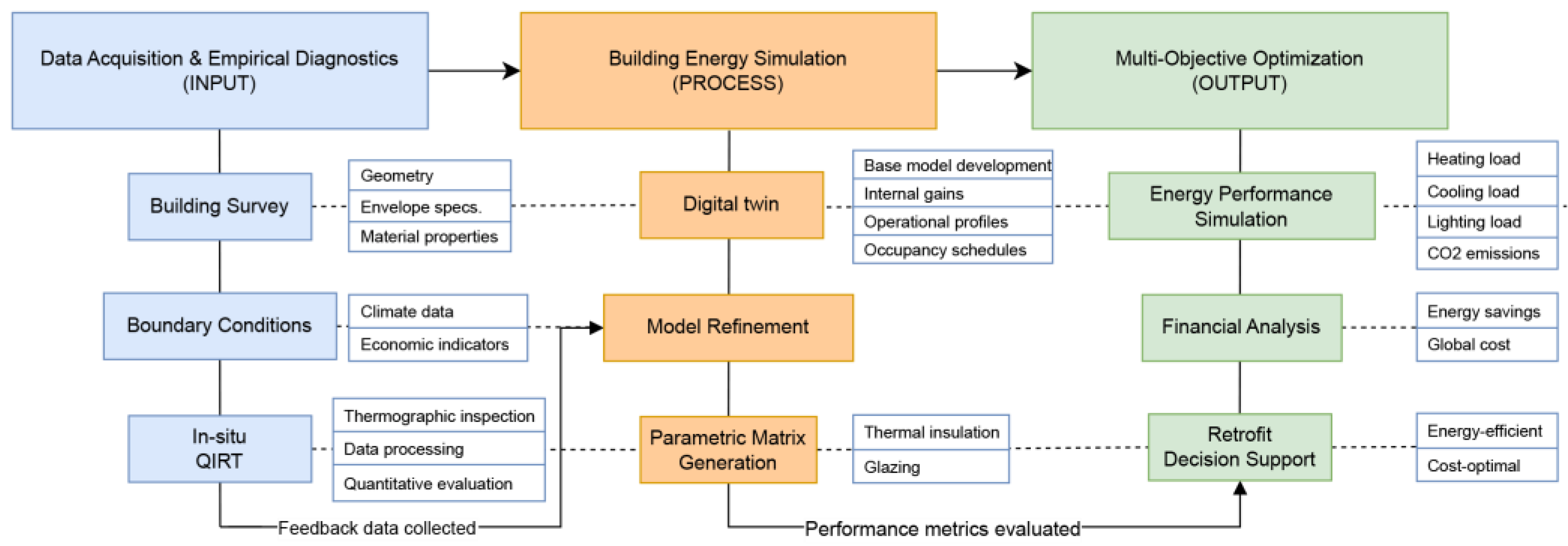
Figure 2.
(a) Site plan of the residential complex [47]; (b) SE façade of the case-study apartment block (source: author).
Figure 2.
(a) Site plan of the residential complex [47]; (b) SE façade of the case-study apartment block (source: author).
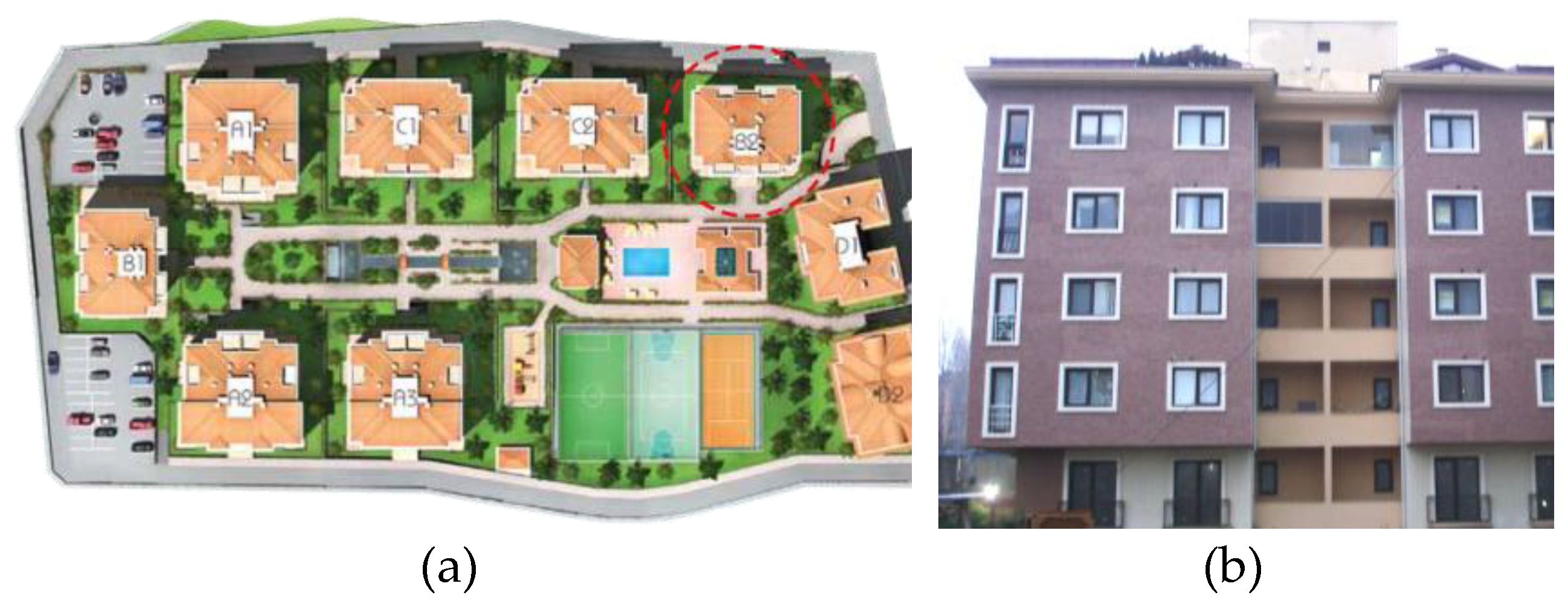
Figure 3.
Plan detail of the external wall interface showing the RC column, the PACB infill, and the window frame (source: author).
Figure 3.
Plan detail of the external wall interface showing the RC column, the PACB infill, and the window frame (source: author).
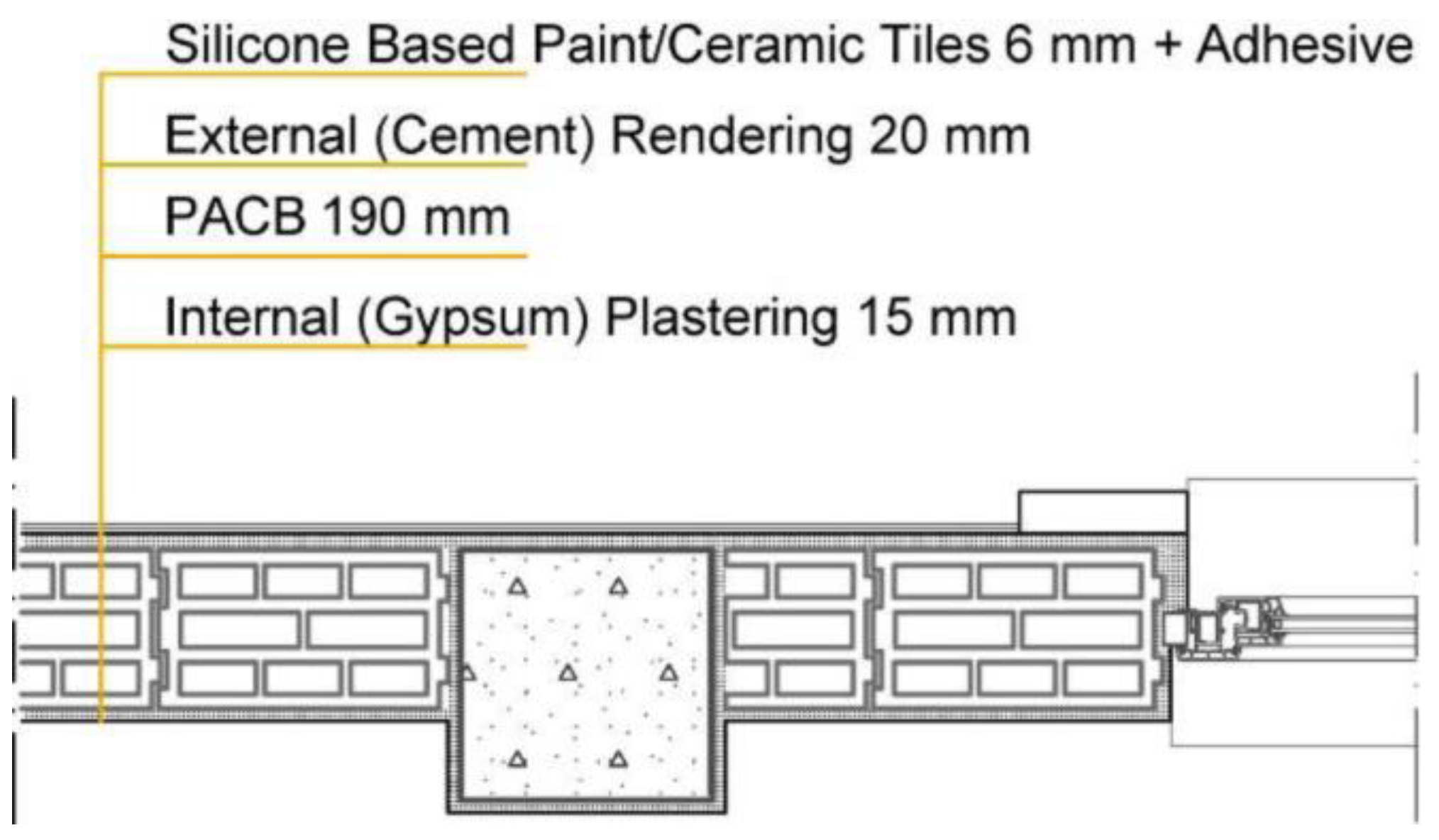
Figure 4.
Normalized hourly occupancy profiles and corresponding system usage frequencies for (a) living room and kitchen, (b) bedrooms, and (c) service areas during weekdays and weekends (source: author).
Figure 4.
Normalized hourly occupancy profiles and corresponding system usage frequencies for (a) living room and kitchen, (b) bedrooms, and (c) service areas during weekdays and weekends (source: author).
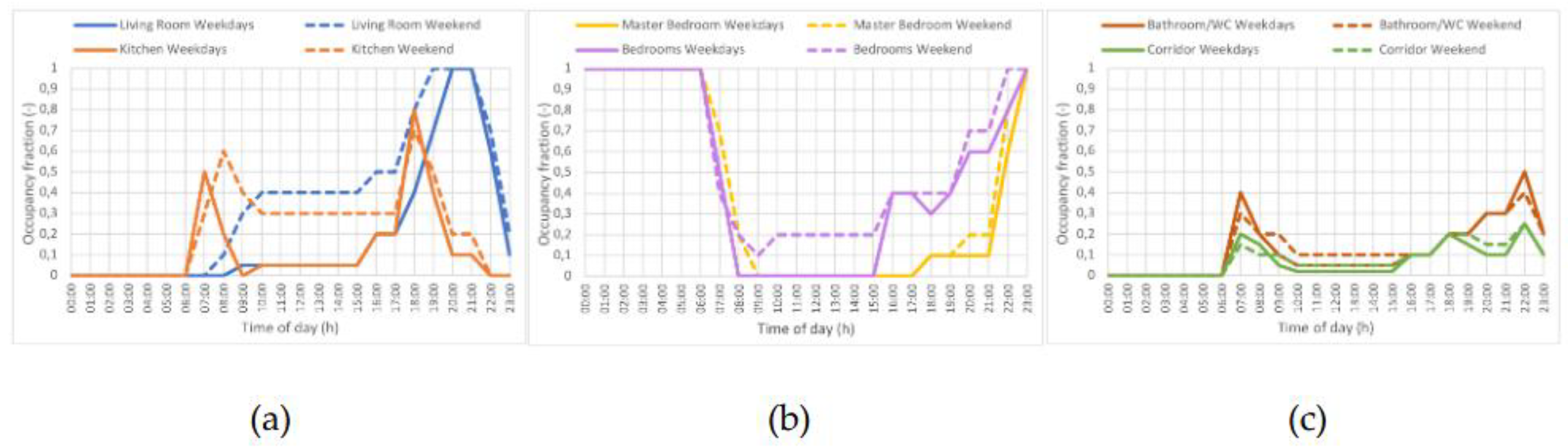
Figure 5.
Relationship between global cost and annual primary energy consumption: Regression analysis and identification of optimal solutions (E1 and C1).
Figure 5.
Relationship between global cost and annual primary energy consumption: Regression analysis and identification of optimal solutions (E1 and C1).
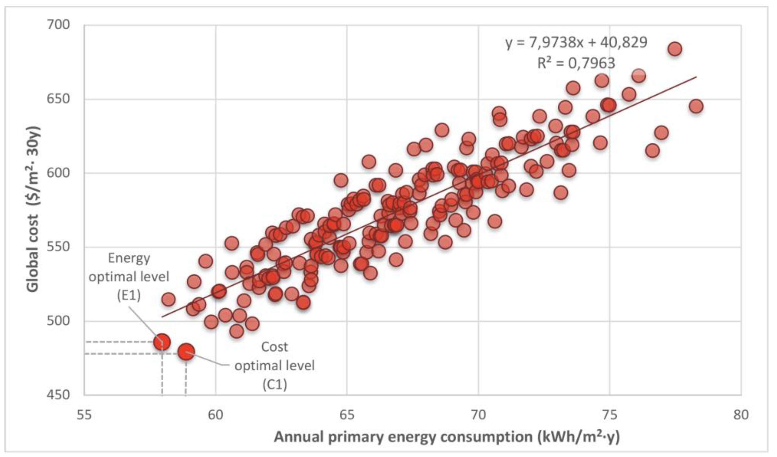
Figure 6.
Pareto optimal solutions for global cost (C) and primary energy consumption (E) ordered by operational carbon emissions relative to the reference building.
Figure 6.
Pareto optimal solutions for global cost (C) and primary energy consumption (E) ordered by operational carbon emissions relative to the reference building.

| External wall Uwall (W/m2K) |
Roof/ceiling Uc (W/m2K) |
Floor Uf (W/m2K) |
Window Uw (W/m2K) |
||||
|---|---|---|---|---|---|---|---|
| 2008 | 2024 | 2008 | 2024 | 2008 | 2024 | 2008 | 2024 |
| 0,60 | 0,40 | 0,40 | 0,30 | 0,60 | 0,35 | 2,4 | 1,8 |
Table 2.
Theoretically calculated thermal transmittance values (UCALC) of external wall configurations according to the data provided in TS 825 standard [5].
Table 2.
Theoretically calculated thermal transmittance values (UCALC) of external wall configurations according to the data provided in TS 825 standard [5].
| Building elements | TS 825 standard code and definition | Material thickness d (m) |
Thermal conductivity λ (W/m·K) |
Thermal resistance R (m2K/W) |
Thermal Transmittance UCALC (W/m2K) |
|---|---|---|---|---|---|
 |
Rsi: Surface heat transfer coefficient | 0.13 | |||
| 4.4: Gypsum plastering | 0.015 | 0.51 | 0.03 | ||
| 7.4.5.6: Pumice aggregate concrete blocks | 0.19 | 0.21 | 0.9 | ||
| 4.2: Cement rendering | 0.02 | 1.6 | 0.01 | ||
| Silicon based paint | - | - | - | - | |
| Rse: Surface heat transfer coefficient | 0.04 | ||||
| Non-insulated cavity wall (Total) | 1.11 | 0.896 | |||
 |
Rsi: Surface heat transfer coefficient | 0.13 | |||
| 4.4: Gypsum plastering | 0.015 | 0.51 | 0.03 | ||
| 5.1: Reinforced concrete | 0.25 | 2.5 | 0.1 | ||
| 4.2: Cement rendering | 0.02 | 1.6 | 0.01 | ||
| Silicon based paint | - | - | - | - | |
| Rse: Surface heat transfer coefficient | 0.04 | ||||
| Non-insulated load-bearing wall (Total) | 0.31 | 3.206 |
Table 3.
Technical specifications of the IR equipment used in the field surveys [50]. .
Table 3.
Technical specifications of the IR equipment used in the field surveys [50]. .
| Parameter | Specification |
|---|---|
| Spectral range | 7.5 – 13 µm |
| Detector type | Focal plane array, uncooled microbolometer |
| Image frequency | 9 Hz |
| Accuracy | ± 2,0 ºC or ± 2% of reading |
| Thermal sensitivity | InfraCAM SD: 0,10 ºC |
| Display | 3.5" color LCD, 18-bit |
| Interpolated resolution | 240x240 pixels |
| Object temperature range | -10 ºC to +350 ºC |
| Laser Pointer | Semiconductor AlGalnP diode, 1 mW, 635 nm |
| Operating temperature range | -15 ºC to +50ºC |
Table 4.
Input data for the reference building energy simulation: Boundary conditions and operational settings.
Table 4.
Input data for the reference building energy simulation: Boundary conditions and operational settings.
| Category | Parameter | Value/Setting |
|---|---|---|
| Climatic Data | Location | Istanbul (41°01'12.7"N, 29°09'43.1"E) |
| Climate zone | Temperate-humid, TS 825 Zone III [6] Köppen Cfa (Humid subtropical) [56] ASHRAE 3C (Warm-Marine) [57] |
|
| Climate data source | TMY (2009–2023) based on Istanbul EPW file [55] | |
| Heating degree day (HDD) | 1846 [55] | |
| Cooling degree day (CDD) | 427 [55] | |
| Annual average temp. / RH | 15.2°C / 72% [55] | |
| Max temp on design day | 32.6 °C [55] | |
| Global solar radiation | 1503 kWh/m2 [55] | |
| Building Geometry and Envelope |
Building type | Multi-story residential building |
| Orientation | 49° to North - South axis | |
| Total conditioned area | 1617 m2 | |
| Apartment layout/ total floor area | 4+1 /165 m2 | |
| Floor-to-floor height | 2.90 m | |
| Roof slope | 33% pitched | |
| WWR | 29.4% NW, 21.3%SE, 24.5% NE and SW | |
| UCALC value of masonry walls | 0,9 W/m2K | |
| UCALC value of load bearing walls | 3,20 W/m2K | |
| UCALC of roof / floor | 0,4 W/m2K | |
| UCALC of ground floor | 0,6 W/m2K | |
| Glazing system/ UCALC | Clear, double glazing /2,4 W/m2K | |
| Tvis of glazing | 82% [58] | |
| SHGC of glazing | 78% [58] | |
| Light reflectance of interior walls | 50 % | |
| Infiltration rate | 0,60 ach | |
| Internal Gains | Lighting / equipment loads | 7 W/m2 / 4 W/m2 |
| Occupancy density | 0,025 persons/m2 | |
| Metabolic rate | 0,86 met | |
| Clothing level | 0.50 clo (summer), 1.0 clo (winter) | |
| Building Service Systems |
Heating system type/ CoP | Natural gas combi boiler / 0,90 |
| Heating setpoint/ setback | 22 °C / 20 °C | |
| Cooling system type/ EER | Electric split air conditioner/ 3 | |
| Cooling setpoint / setback | 25 °C / 26 °C | |
| Natural ventilation, air vent. rate | 10 L/s–person | |
| Heating system operating hours | 06:00–00:00 (heating season) | |
| Cooling system operating hours | 24/7 (cooling season, conditioned by occupancy) | |
| Lighting system operating hours | 07:00–00:00 (daily, linked by room occupancy) |
Table 5.
Thermophysical properties, thickness, unit prices, and service life of external wall insulation scenarios [60,61].
| Scenario no | Insulation material |
Thickness (cm) |
Thermal conductivity (W/m·K) |
Uwall (W/m²·K) |
Unit price ($/m²) |
Estimatedservice life (years) |
|---|---|---|---|---|---|---|
| INS1 | EPS | 6 cm | 0,034 | 0.377 | 3.62 | 25 – 50 |
| INS2 | 8 cm | 0.309 | 4.80 | |||
| INS3 | 10 cm | 0.261 | 6.00 | |||
| INS4 | 12 cm | 0.226 | 7.27 | |||
| INS5 | XPS | 6 cm | 0,035 | 0.384 | 7.98 | 35 – 50 |
| INS6 | 8 cm | 0.315 | 10.65 | |||
| INS7 | 10 cm | 0.267 | 14.64 | |||
| INS8 | 12 cm | 0.232 | 20.01 | |||
| INS9 | Stone wool |
6 cm | 0,039 | 0.412 | 10.80 | 30 – 60 |
| INS10 | 8 cm | 0.340 | 14.40 | |||
| INS11 | 10 cm | 0.290 | 17.98 | |||
| INS12 | 12 cm | 0.252 | 21.58 |
Table 6.
Thermophysical, optical properties and unit prices of glazing scenarios [58].
Table 6.
Thermophysical, optical properties and unit prices of glazing scenarios [58].
| Scenario no |
Double pane combination | Gap filling | Tvis (%) |
SHGC (%) |
Uglazing (W/m²·K) |
Unit price ($/m²) |
|---|---|---|---|---|---|---|
| Ref | 4 mm clear float + 12 mm gap + 4 mm clear float | Air | 82 | 78 | 2.4 | 32.96 |
| G1 | 4 mm low-e + 16 mm gap + 4 mm clear float | Air | 79 | 56 | 1.4 | 37.18 |
| G2 | Argon | 79 | 56 | 1.1 | 42.25 | |
| G3 | 4 mm solar low-e + 16 mm gap + 4 mm clear float | Air | 72 | 45 | 1.4 | 40.56 |
| G4 | Argon | 72 | 45 | 1.1 | 45.63 | |
| G5 | 6 mm solar low-e + 16 mm gap + 6 mm clear float | Air | 69 | 40 | 1.4 | 57.46 |
| G6 | Argon | 69 | 40 | 1.1 | 62.54 | |
| G7 | Air | 69 | 37 | 1.3 | 57.46 | |
| G8 | Argon | 69 | 37 | 1.1 | 62.54 | |
| G9 | Air | 63 | 43 | 1.4 | 57.46 | |
| G10 | Argon | 63 | 43 | 1.1 | 62.54 | |
| G11 | 4 mm clear float + 16 mm gap + 4 mm temperable solar low-e | Air | 79 | 63 | 1.4 | 73.52 |
| G12 | Argon | 79 | 63 | 1.1 | 78.59 | |
| G13 | 6 mm temperable low-e + 16 mm gap + 6 mm clear float | Air | 72 | 54 | 1.4 | 60.85 |
| G14 | Argon | 72 | 54 | 1.1 | 65.92 | |
| G15 | 6 mm temperable solar low-e + 16 mm gap + 6 mm clear float | Air | 58 | 32 | 1.4 | 76.90 |
| G16 | Argon | 58 | 32 | 1.1 | 81.97 |
Table 7.
Economic parameters used in the global cost analysis (2016-2025).
| Parameter (symbol) | Value (unit) | Source |
|---|---|---|
| Inflation rate (Ri) | 29,74% | FRED, CBRT [63,64] |
| Market interest rate (R) | 20,33% | CBRT, FRED [65,66] |
| Reel interest rate (Rreal) | - 7,25% | Calculated |
| Electricity escalation rate (ee) | 28,65% | Calculated |
| Natural gas escalation rate (eg) | 36,87% | Calculated |
| 1 USD Dolar exchange rate ($) | 35,50 TL | CBRT [67] |
| Electricity unit price (Pe) | 2,97 kWh/TL | EMRA (tax included) [68] |
| Natural gas unit price (Pg) | 0,795 kWh/TL | İGDAŞ (tax included) [69] |
| Note: Energy prices reflect January 2025 residential tariffs: high-tier (>240 kWh/m) for electricity and standard tier (<100,000 m³/y) for natural gas. | ||
Table 8.
Thermal anomaly inspection points and building envelope junctions identified via IRT.
| Target area (code) | Building envelope components | IR camera inspection points on the floor plan | |
|---|---|---|---|
| I (Masonry wall) |
I-A | Masonry wall | 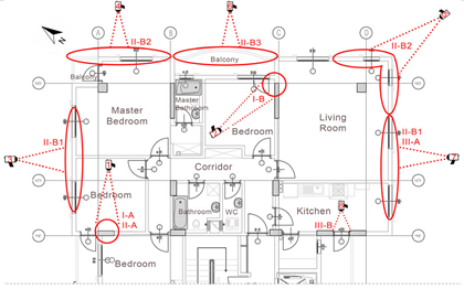 |
| I-B | Wall/wall corner | ||
| I-C | Wall/ground | ||
| II (RC structural frame) |
II-A | Column/beam | |
| II-B1 | Intermediate floor | ||
| II-B2 | Cantilevered floor | ||
| II-B3 | Balcony floor slab | ||
| II-B4 | Roof slab | ||
| II-C | Basement shear wall | ||
| III (Fenestration) |
III-A | Window | |
| III-B | Door | ||
| IR camera inspection points on the building elevations | |||
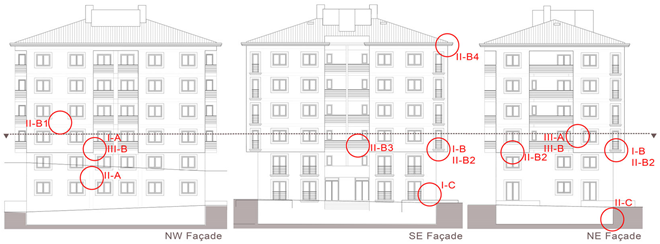 | |||
Table 9.
Actual thermal transmittance (UINSITU) and temperature index (TI) values for the case study building’s envelope, with reference and defect points for thermal failure in each IR image.
Table 9.
Actual thermal transmittance (UINSITU) and temperature index (TI) values for the case study building’s envelope, with reference and defect points for thermal failure in each IR image.
| Thermal camera no | Thermogram | Photograph | Measurement Conditions |
Target area (code) |
UINSITU (W/m2K) |
Temperature Index, TI (Unitless) |
|
|---|---|---|---|---|---|---|---|
| Indoor | Outdoor | ||||||
| 1 | 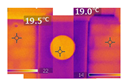 |
 |
Tin: 20.1°C RHin: 58% vin: 0.15 m/s |
Tout: 13.6°C RHout: 77% vout: 1 m/s |
Reference (I-A) | 1.30 | 0.83 |
| Thermal bridge (II-A) | 4.55 | 0.58 | |||||
| 2 | 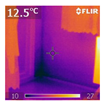 |
 |
Tin: 17.2°C RHin: 61% vin: 0.2 m/s |
Tout: 8.0 °C RHout: 82% vout: 1.5 m/s |
Reference (I-A) | 2.71 | 0.35 |
| Surface condensation (I-B) | 6.34 | 0.82 | |||||
| 3 | 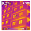 |
 |
Tin: 18.8°C RHin: 52% vin: 0.15 m/s |
Tout: 6.5 °C RHout: 74% vout: 1.5 m/s |
Reference (I-A) | 1.50 | 0.86 |
| Thermal bridge (II-B1) | 3.61 | 0.67 | |||||
| 4 | 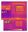 |
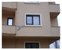 |
Tin: 17.4°C RHin: 61% vin: 0.2 m/s |
Tout: 8.0 °C RHout: 77% vout: 1.4 m/s |
Reference (I-A) | 1.16 | 0.88 |
| Thermal bridge (II-B2) | 3.72 | 0.63 | |||||
| 5 | 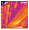 |
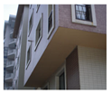 |
Tin: 17.4°C RHin: 48% vin: 0.15 m/s |
Tout: 6.2 °C RHout: 71% vout: 1.6 m/s |
Reference (I-A) | 1.15 | 0.89 |
| Thermal bridge (II-B2) | 4.03 | 0.62 | |||||
| 6 | 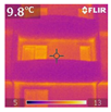 |
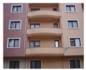 |
Tin: 17.8°C RHin: 56% vin: 0.15 m/s |
Tout: 7.0 °C RHout: 80% vout: 1.5 m/s |
Reference (I-A) | 2.10 | 0.79 |
| Thermal bridge (II-B3) | 3.42 | 0.67 | |||||
| 7 | 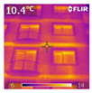 |
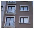 |
Tin: 18.1°C RHin: 53% vin: 0.1 m/s |
Tout: 6.6 °C RHout: 74% vout: 1.5 m/s |
Reference (I-A) | 1.34 | 0.87 |
| Thermal bridge (II-B1) | 3.41 | 0.67 | |||||
| Air leakage (III-A) | 2.33 | 0.77 | |||||
| 8 | 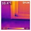 |
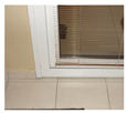 |
Tin: 18.2°C RHin: 56% vin: 0.2 m/s |
Tout: 8.1 °C RHout: 83% vout: 1.5 m/s |
Reference (I-A) | 3.65 | 0.52 |
| Warm air leakage (III-B) | 5.94 | 0.23 | |||||
Table 10.
Improvement rates (%) in energy, environmental, and economic performance metrics for Pareto-optimal solutions relative to the reference building.
Table 10.
Improvement rates (%) in energy, environmental, and economic performance metrics for Pareto-optimal solutions relative to the reference building.
| Retrofit option | Improvement rate (%) | |||||||
|---|---|---|---|---|---|---|---|---|
| Scenario no |
Thermal insulation |
Glazing | Heating energy |
Cooling energy |
Lighting energy |
Carbon emissions |
Primary energy |
Global cost |
| E1-C2 | INS4 | G12 | 65.7 | 19.9 | 2.7 | 50.9 | 53.0 | 51.3 |
| E2 | INS8 | G12 | 65.4 | 19.9 | 2.7 | 50.7 | 52.8 | 48.4 |
| E3-C1 | INS4 | G2 | 63.8 | 29.0 | 2.7 | 50.4 | 52.2 | 51.9 |
| E4-C8 | INS8 | G2 | 63.6 | 28.9 | 2.7 | 50.2 | 52.0 | 49.0 |
| E5 | INS12 | G12 | 64.4 | 19.9 | 2.7 | 50.0 | 52.0 | 47.2 |
| E6-C9 | INS4 | G14 | 63.4 | 31.1 | 1.5 | 50.0 | 51.8 | 48.7 |
| E7 | INS8 | G14 | 63.1 | 31.1 | 1.5 | 49.8 | 51.6 | 45.8 |
| E8-C5 | INS4 | G12 | 63.8 | 19.7 | 2.2 | 49.5 | 51.5 | 49.9 |
| E9 | INS7 | G12 | 63.6 | 19.8 | 2.2 | 49.3 | 51.2 | 47.8 |
| E10 | INS12 | G2 | 62.5 | 28.8 | 2.7 | 49.4 | 51.2 | 47.8 |
| C7 | INS4 | G11 | 63.0 | 21.5 | 2.7 | 49.1 | 51.0 | 49.4 |
| C3 | INS3 | G2 | 62.0 | 28.7 | 2.2 | 48.9 | 50.7 | 50.5 |
| C6 | INS4 | G4 | 60.7 | 41.8 | 1.5 | 48.9 | 50.6 | 49.5 |
| C4 | INS4 | G1 | 61.1 | 30.2 | 2.7 | 48.4 | 50.2 | 50.0 |
| C10 | INS3 | G1 | 59.2 | 29.9 | 2.2 | 46.9 | 48.6 | 48.6 |
Disclaimer/Publisher’s Note: The statements, opinions and data contained in all publications are solely those of the individual author(s) and contributor(s) and not of MDPI and/or the editor(s). MDPI and/or the editor(s) disclaim responsibility for any injury to people or property resulting from any ideas, methods, instructions or products referred to in the content. |
© 2026 by the authors. Licensee MDPI, Basel, Switzerland. This article is an open access article distributed under the terms and conditions of the Creative Commons Attribution (CC BY) license (http://creativecommons.org/licenses/by/4.0/).
Copyright: This open access article is published under a Creative Commons CC BY 4.0 license, which permit the free download, distribution, and reuse, provided that the author and preprint are cited in any reuse.