
Submitted:
20 February 2026
Posted:
25 February 2026
You are already at the latest version
Abstract
This work presents an investigation of two cooling systems used in additive friction stir depositions (AFSD) and the related effect on process temperature, feed material, and life of processing equipment. A new AFSD cooling system, Mazak MegaStir Liquid-cooled Toolholder (LCTH), was integrated onto MELD Manufacturing AFSD machines using both continuous and discrete material feeding systems. The LCTH is compared to the original MELD cooling system to understand how process temperatures are controlled by the cooling system, how feed material interacts with the process under different cooling conditions, and how well the cooling systems protect the equipment. It is shown that both the original MELD cooling system and the LCTH can deposit Al-Mg-Si alloy (AA6061) for large scale depositions. Four configurations of tool and cooling system are discussed. Configurations with short working face to cooling distances shows the best potential robust operation of AFSD at bulk scales.
Keywords:
AFSD
; processing
; tooling
; AA6061
; process control
; bulk deposition
1. Introduction
Metal based additive manufacturing (MAM) is of interest to many industries ranging from biomedical to aerospace for both repair and new build of many materials [1]. MAM is largely broken into two major categories: solidification based and solid-state based processes [2,3]. Solidification based processes comprise of three main types: powder bed fusion, binder jetting, and directed energy deposition [4]. With both advantages and disadvantages, each of these MAM categories has a specific use case that it is well suited for. Solidification based MAM tend to have defect types including: lack of fusion, voids, porosity, cracks, delamination, and residual stresses [5,6]. These defects are inherent to the materials and the processes utilized.
Additive friction stir deposition (AFSD) is a new large area, solid state MAM process. AFSD is capable of many additive techniques: deposition, joining, repair, and cladding [7,8]. The solid-state nature of the process prevents many of the solidification-based defects previously discussed [2]; however, delamination and residual stress may still be concerns [9,10,11,12]. AFSD has the potential to be a replacement technology for forging components [13,14,15]. AFSD is capable of depositing in an open environment, allowing for large depositions with less size constraints than powder bed fusion or binder jetting [16,17]. The use of solid bar feed stock also makes AFSD more environmentally conscious than powder or wire-based feed common in powder bed fusion, binder jetting, and directed energy deposition [8]. AFSD has a deposition rate that is approximately ten times faster than solidification processes [18]. The rapid, solid state, and open environment capabilities of this process are many of the advantages that the AFSD process has over traditional methods.
AFSD is a relatively new MAM process but is being studied widely. The process has been evaluated for many material systems: Al [19,20,21,22], Mg [23,24], Fe [14,25], Ni [26,27], Ti [28], Cu [29]. Generally, solid feed material is used of ~9.5 mm2 or ~13 mm2 cross section but powder and chips are also possible formats for feed material [17]. AFSD process deposits through a thermomechanical mechanism utilizing frictional heating and rotational deformation rather than a solidification mechanism [30]. The process is capable of being utilized by large-scale machines for components or deposition, currently the largest machine has a 6x9x4 m print volume possible [31,32]. The use of solid bar feed material and thermomechanical processing enables successful depositions across a wide variety of material systems and component sizes.
One of the next critical steps for industrial implementation is transitioning the scale of AFSD from academic or research to industrial. Despite numerous material systems being explored in literature, many continue to use very small deposition sizes that exhibit vastly different thermal conditions than what has been observed at the industrial scale. The transition from academic size machines and depositions will require an understanding of the role of cooling in the AFSD process. This understanding will need to include the thermal impact on feed material, equipment life, and the process during AFSD; in order to facilitate a transition from small research depositions to large, full-scale components for industry application.
2. Materials and Methods
2.1. Machinery
For this work a MELD L3 and a CD-14, from MELD Manufacturing Corporation, were used for AFSD builds. Both systems use a hollow rotating 38mm diameter tool through which solid, square feed material is fed. The feed material is deformed against the previous layer or substrate, which generates heat and joins the two together through diffusion bonding that has been accelerated with increases temperature and pressure. Both the L3 and CD-14 have a manufacturer cooling system that consists of an upper and lower seal with coolant flowing directly in contact with the tool, this system is referred to as MELD throughout. A new AFSD cooling system, Mazak MegaStir Liquid-cooled Toolholder, that will be referred to as LCTH throughout, was integrated with the deposition machines. The LCTH is an integrated toolholder and cooling system, while MELD is a two-component system. With the new LCTH system, the tool is indirectly cooled by the tool holder through metal-on-metal contact between tool and holder.
The MELD and LCTH system have several differences: flow style, cooling style, cooling area, and coolant flow rate. The MELD system uses a vacuum style pump that pulls the coolant at ~8 liters per minute through the cooling loop to directly cool ~2000 mm2 of tool area before returning to a reservoir. The reservoir is chilled by an external chiller. The LCTH system uses a pressure style pump to push the coolant through the 15,000 mm2 area of the cooling loops within the tool holder. This coolant flows through the toolholder directly from the external chiller at ~12 liters per minute. The tool is held in the LCTH with ~8,000 mm2 of chilled tool surface area contact. See Table 1 for a summary of these cooling systems.
Process data was collected using the included data acquisition system (DAQ) on the L3 and CD-14 machines. Both DAQs were configured to utilize a K-Type thermocouple in the deposition tool and recorded by the DAQ wirelessly. The L3 DAQ collected temperature (℃) from two locations: at the tool face and at the bearing low in the spindle. The L3 machine utilized in the study could record at a maximum of one hertz. The CD-14 DAQ collected tool temperature (℃) at 20 hertz but bearing temperature was not available.
2.2. Experimentation and Evaluation
2.2.1. Spindle Bearing Temperature Baseline
To understand the impact of spindle rotation rate on spindle bearing temperatures, a simple experimental design was conducted to test the full range of rates used during depositions. Two tool cooling states were used to impact the temperature of the spindle bearing: cooled and uncooled spindle rotation. During the uncooled tests, no tool cooling was used while rotating the machine spindle at a constant rotation rate for 90 minutes. This was done for five rates: 100, 200, 300, 400, and 500 rpm. During the cooled tests, these tests were repeated for each rate; however, a 90-minute period of pre-cooling was implemented before engaging the spindle, and coolant flow continued for the duration of the test. Starting conditions were preserved by allowing 24 hours between tests to allow the system and equipment to completely restabilize thermally.
2.2.2. Cooling System Comparison
To compare the cooling systems effect on machine critical temperatures, specifically the temperature of the spindle bearing, a build was produced using three experimental conditions: no cooling, MELD cooling system, and LCTH cooling system. A path geometry was selected that maximized localized heat input. The planned path will result in a deposition that is ~150 x 150 mm2 and ~200 mm tall using 100 layers of ~2 mm thickness. For each condition this path plan was attempted. These depositions were made on the MELD L3 in a discrete manner, where after each layer was deposited, the process was halted to allow for reloading of feed material and then resumed in an automated fashion. Each condition was tested layer by layer until the deposition failed to continue deposition or the deposition stack became too unstable to continue with the next layer.
This experiment utilized tools with a square ~10 x 10 mm2 through hole with no face features. Each tool was made of H13 and had internal features following the internal geometric consideration previously described in work done by Brigham Young University [33]. Each tool had a five-degree draft angle with a draft depth of 20 mm and a 45-degree chamfer angle with a chamfer depth of ~0.5 mm from the tool face. The featureless tool deposited material with a constant 350 rpm spindle speed and material was fed at 380 millimeters per minute while the tool translated at 650 millimeters per minute. All depositions were made without graphite contamination. Commercially available 6061-T6511 aluminum extrusion was used to make ~525 x 9.5 x 9.5 mm3 long pieces of feed material. Substrates were produced from commercially available ~9.5 mm thick 6061-T651 plates of ~300 x 300 mm2. Substrates were cleaned with isopropyl alcohol to remove oils and sanded to remove thick oxide layer with 80 grit sandpaper. Both feed material and substrates were of nominal chemical composition as shown in Table 2.
2.2.3. Cooling Configuration Comparison
Additional three-dimensional depositions were produced to compare tool lengths and cooling systems in four configurations. This experiment utilized H13 tool bodies with a ~13 mm2 through hole with internal features following the internal geometric consideration previously described [33]. Each tool has two sets of positive protruding teardrops on the face of the tool, alternating 90 degrees apart from each other with two protrusions per set. Each set of teardrops are arranged on two diameters of 25.4 mm and 31.8 mm; the protrusions have a depth of ~2.3 mm and ~1.5 mm, for the two diameters respectively. These design features and details can be seen in Figure 1. All depositions were made without the use of graphite lubricant on the feed material. Feed material was made of commercially available 6061-T6511 aluminum extrusion cut to ~525 x 12.7 x 12.7 mm3 long and made of nominal chemical composition as shown in Table 2.
These depositions are ~100 mm in diameter and ~160 mm in height in a helical path with individual layers being ~2 mm in thickness. These depositions were made on a MELD L3 in a discrete manner as described above; however, four layers were able to be deposited from each piece of feed material before needing to reload material. Depositions were performed on a substrate of an aluminum 6061-T6 plate with dimensions of ~200 x ~200 x 9.5 mm3. The substrate was stacked on top of another identical plate used as a backing or anvil plate. Each configuration was tested using the same process parameters. Depositions were all done using a 210 rpm spindle rotation rate, ~340 mm/min tool traverse rate, and 190 mm/min material feed rate.
Depositions were made using four configurations of two cooling systems and two distances between the tool face and cooling system, referred to as DC. The first two configurations used the MELD cooling system where coolant directly cools the tool and can be placed anywhere along the length of the tool, see purple representations of MELD system in Figure 2a and Figure 2b. The MELD system has two extreme DCs possible: ~12 mm and ~36 mm, for ease of reference these will be referred to as MELD-S and MELD-L respectively. The second two configurations use the LCTH with indirect cooling applied to the tool. The cooling system is fixed in position, so two different tool lengths were utilized to adjust the DC: ~12 mm and ~47 mm, for ease of reference these will be referred to as LCTH-S and LCTH-L respectively. Figure 2 shows these four configurations with representation of the two cooling systems.
2.2.4. Thermal Effects on Feed Material
Microhardness line traces were performed on the used feed material from the cooling configuration builds. After each stop the remaining feed material is ejected from tool and collected. The line traces were done on four ejected feed rods for each cooling configuration test: the first, second, 10th, and 21st bars. The deformed end of the feed material was milled to return it back to prismatic dimension before sanding and polishing to a mirror finish using: 240, 400, 600, 800, 1200, and 1200 fine grit sandpapers then 1 micron alumina suspension polish on a LECO PX300 Manual Polisher. Microhardness line traces were done on a Clark Instrument CM-402-AT with 500-gram mass at 10 second dwell with 0.5 mm spacing along a 50 mm path resulting in 100 Vickers hardness data points per trace. The line traces start with 1st indent being 0.25 mm from the deformed end of the feed material and 100th indent is towards the undeformed end of the feed material. For each configuration, the hardness data collected is smoothed using a seven-point-window moving average for each trace then averaged for each bar for one resulting profile per configuration.
2.2.5. Continuous Vs Discrete
The same ~100 mm diameter helical depositions were also completed on a CD-14 AFSD machine as were made on the discrete L3 AFSD machine. This CD-14 machine has continuous deposition capability and as such does not have reload breaks. Two of the cooling configurations were duplicated on this machine with continuous deposition: both from the LCTH system and the short DC from the MELD system. These configurations were repeated based on initial deposition results. The LCTH tools were identical H13 tools used previously. The tool for MELD system on the CD-14 uses Cu-Be alloy as body material with H13 as face material rather than using H13 for the entire tool. This Cu-Be tool is the manufacturer provided solution for graphite or contaminant free deposition of aluminum alloys. The same tool face features were present as the tooling used for the discrete configuration testing. The Cu-Be tool, however, did not have any internal geometric changes (i.e., draft or chamfer) but were straight square through hole tools.
3. Results and Discussion
3.1. Baseline Bearing Temperatures
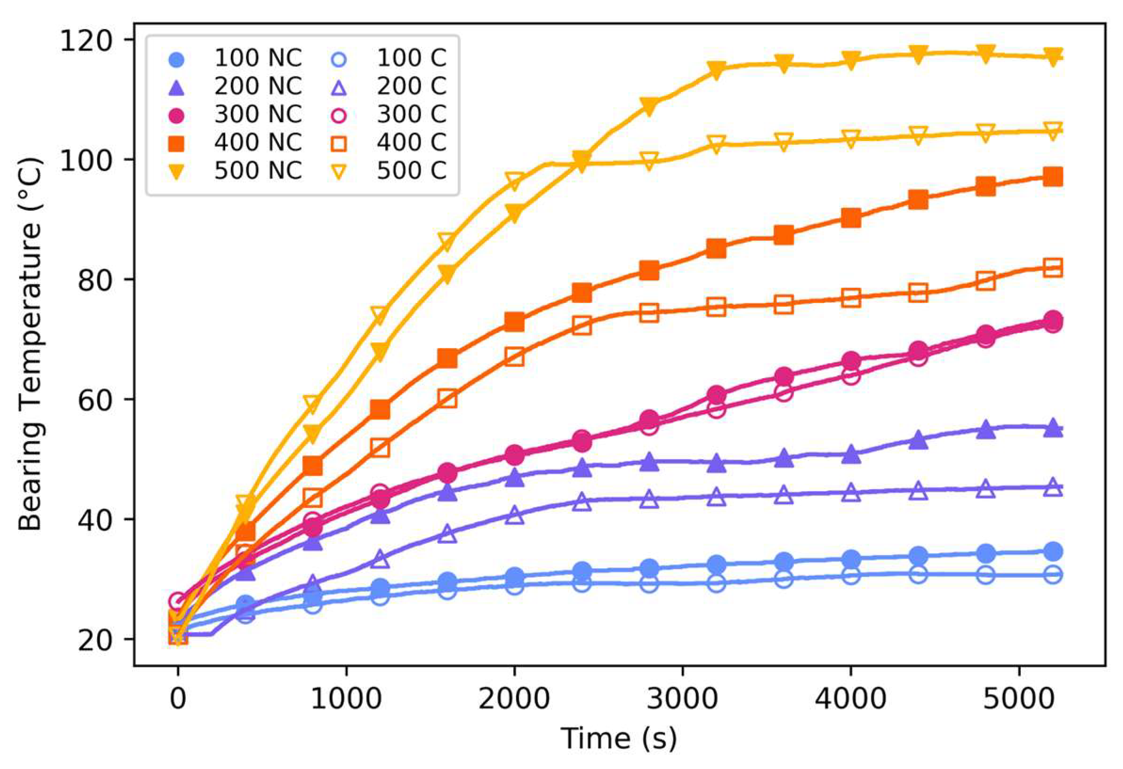
As the spindle operates, heat is generated through friction within the bearing assembly. This frictional heat could increase the temperature of the bearings if not managed. To understand the cooling systems’ ability to protect the critical spindle and spindle bearings, a baseline must be established for bearing temperatures with only spindle rotation and no external thermal loads. Regardless of the cooling system utilized, an increase in spindle rotation rate increases the bearing temperatures, as can be seen in Figure 2 by comparing each color of curves. Each spindle rotation rate increase of 100 rpm from 100 to 500 rpm increased the bearing temperature by approximately 15, 28, 9, 23 ℃ respective to each rate increase. This shows that for only a 90-minute spindle rotation condition, increasing rotation rate by 100 rpm increases the spindle bearing temperature by ~20 ℃. This follows expectation that additional frictional heating would occur with an increase in rotational velocity within the bearings.
With the impact of spindle rotation rate established, cooling systems can now be considered for the no load spindle bearing temperature. For each rotation rate tested between 100 and 500 rpm, the cooling systems decreased the bearing temperature by approximately 4, 10, 0, 15, 13 ℃ each compared to the no cooling condition. For each rotation rate, utilization of cooling decreased the spindle bearing temperature by ~9 ℃ on average. The utilization of cooling decreases the temperature of spindle bearings for a given rotation rate when compared to no cooling. This can be seen in Figure 2 by comparing curves with filled and hollow markers of the same color. The impact of cooling versus no cooling is less impactful than the rotation rate used. This trend is logical due to relatively low contact area between the spindle and the cooling system.
Spindle bearing temperature is an important factor for the life of AFSD equipment. If spindle life is decreased due to high bearing wear, related to high bearing temperatures, this can be detrimental to the life of the component. The MELD user manual states that, “The maximum operating temperature for the bearings is [99 ℃]”[35]. With no thermal load, spindle rotation rates above 500 rpm exceed the spindle bearing limit, this can be seen by both types of inverted triangle in Figure 2. It also seems likely that 400 rpm with no cooling also will surpass the bearing temperature limit if the spindle was run for a longer duration. This suggests that spindle rotation rate selection should be considered when developing parameters to enable bulk deposition of aluminum using MELD AFSD equipment. This would typically not be a problem because deposition spindle rotation rates are significantly lower for aluminum depositions but should be considered for equipment protection.
Figure 3.
Comparison of Spindle bearing temperatures over time for 5 different spindle rotation rates (RPMs) and 2 different conditions (cooled and uncooled). Open shapes are not cooled (NC) and filled shapes are cooled (C).
Figure 3.
Comparison of Spindle bearing temperatures over time for 5 different spindle rotation rates (RPMs) and 2 different conditions (cooled and uncooled). Open shapes are not cooled (NC) and filled shapes are cooled (C).
3.2. Cooling System Comparison
To test the cooling systems three large depositions were attempted. For the control, a no cooling deposition was attempted and had very limited ability to deposit. During this deposition, two complete layers were deposited. These layers were of normal quality and process forces; this can be seen in Figure 4a. Shortly after starting the third layer, the print failed to deposit material, due to swaging or material deformation inside the tool. Swaging of feed material reduces the force being applied to the deposition because of frictional drag inside the tool. The no cooling attempt was used as a control to confirm the necessity of cooling for aluminum deposition; it seems likely that cooling would be a necessity for any AFSD deposition at meaningful scale.
In contrast to the control, both cooling systems performed very well. These depositions were completed with normal forces and quality. Utilizing the MELD cooling system, the full planned build height was completed. However, while using LCTH cooling system, the deposition was unable to complete the full height, 100 layers, due to first layer adhesion issues. These depositions were done with flat or featureless tooling, which has poor interlayer and especially layer to substrate interaction. Additionally, any increase in cooling could cause the material to deform less readily with the substrate material. Future work using knub tools has eliminated this concern [36]. When cooling is utilized either system produced meaning full depositions of large scale.
Analyzing the first 50 layers of each build, approximately four hours of deposition, both cooling systems appear to maintain the spindle bearing temperatures equally effectively. Despite the difference in the cooling system, detailed in Table 1, the spindle bearings’ temperatures were relatively equal for both systems at the same stage in the builds. By layer 50 both spindle bearing sets had heated to ~70 ℃ regardless of system, see Figure 5. Despite differing slightly in temperature leading up to the end of the test, the final bearing temperatures of these two builds are the same in the end.
There appears to be low thermal contribution from the process to the spindle bearings, especially when cooling is utilized. When compared to the baseline spindle temperature profiles from the no thermal load study previous discussed, continuous spindle rotation related friction would result in bearing temperature of ~80 ℃, see Figure 5. Each deposition build, by layer 50, had only generated enough heat for the spindle to be at ~70 ℃, as shown in Figure 5 which is expected because these depositions do not have continuous spindle activity. These depositions each have about one minute between layers with the spindle stopped. This is due to the discrete nature and needing to reload the feed material after each layer.
3.3. Cooling Configuration
The helical depositions exploring the impacts of various configurations of DC and cooling system found that each configuration seemed to have similar deposition quality. Each deposition has generally clean edges and similar surface texture both on the top surface and the side of the depositions. All helical depositions were completed in each configuration without any deviation from planned height, this can be seen in Figure 6. This demonstrates that each configuration is capable of being used for deposition of AA6061 and can produce similar surface quality.
Despite each system being capable of depositing AA6061 there are differences in thermal impact to the process and feed material. As shown in Figure 7, each configuration has a unique tool temperature during deposition. The MELD-S appears to have most consistent deposition temperature of ~450 ℃ for the entire deposition. The MELD-L had the highest process temperatures during the second half of the deposition, 2500s to end. LCTH-S had the lowest process temperatures for the second half of the deposition. The LCTH-L has very similar temperature profile to the MELD-L, except it remained slightly cooler in the last half of the deposition. There is a notable difference in the temperature achieved for short and long DC, being approximately 40 ℃ hotter for long DCs. This indicates that the DC is an important process parameter that needs to be controlled due to its relationship with the achievable process temperatures. Additionally, the DC plays a role in enabling the process by preventing feed material from deforming and swaging into the tool, which can interrupt and prevent the deposition process. Therefore, the DC is a parameter that requires judicious manipulation to control process temperature while enabling processing.
Although the effective length of the tool or the DC has the largest impact on process temperature, the cooling system is also an unneglectable factor to the thermal system. Utilizing the LCTH for long DC and short DC tools, the deposition temperature were reduced by ~2.5 ℃ and ~15.0 ℃, respectively. The length of the DC magnifies the impact of the cooling system because the LCTH is more effective, as shown by the steeper gradient, with the short DC tools than with the long DC tools. LCTH has an increased cooling ability compared to the MELD cooling system, but both are viable cooling system for deposition of aluminum 6061. Also, the MELD-S appears to have the most consistent deposition temperature of ~450 ℃ for the entire deposition. Consistency is highly desirable for the AFSD process, which the MELD-S was able to achieve successfully in the discrete system. It is clear that the cooling system and the length of DC both impact the process temperature.
3.4. Feed Material Evaluation
The tool DC impacts the ability of the cooling system to prevent feed material strength degradation. AA6061 is a precipitate strengthened aluminum alloy, meaning that with increased thermal input, the material becomes weaker due to precipitate coarsening. This coarsening decreases the hardness of the material. If temperatures are additionally elevated, then the strengthening precipitates can be put back into solution and precipitate during natural aging process. This phenomenon can be seen in the ‘check mark’ shape of each of the hardness plots in Figure 8, where the material to the left of the check mark (at the minima found at ~2-4 mm) has increased strength because of natural aging while material to the right has experienced over aging and the material has degraded, causing the strength to not be recovered during natural aging.
The extent of this over aging negatively impacts the strength of material entering process or the feed material hardness. This degradation can cause premature deformation, deformation inside the tool, that can prevent deposition. In Figure 8 shorter tools had decreased thermal effect on the feed material, i.e., minimized heat affected zone (HAZ) depth. These long tools have HAZ that are 10 mm deeper than those seen in the short tools, ~28 mm rather than ~18 mm for long HAZ and Short HAZ. It is also important to note that the MELD-L tool has ~10mm shorter DC than the LCTH-L because of the limitations of the tooling, see Figure 2. The MELD-L has a DC that is shorter than that of the LCTH-L, despite this it thermally softened the feed material equally to that of the longer LCTH-L. This equivalent thermal softening but short length is evidence that the MELD cooling system has a reduced cooling impact or ability.
Each of the tools explored in the study have ~20 mm of draft depth, which appears to affect the cooling systems’ efficacy. Short DC tools were able to maintain feed material strengths within in the draft where contact between tool and cooling would not be possible geometrically. In configurations with a short DC the strength was unaffected ~2 mm into the draft from the feed direction. In contrast configurations with long DC could not maintain these strengths even inside the undrafted feed section of the tool. Material degradation occurred ~10 mm before the draft, up the tool, from the feed direction in long DC tools. These differences show that short DC tools have improved control of the process when compared to long DC tools.
Additional to the materials’ precipitate strength, the yield strength is negatively correlated with temperature. In the temperature range of 25 to 500 ℃ seen during AFSD processing, the yield strength drops from ~280 MPa to ~10 MPa for AA6061, as seen in Figure 9. This significant decrease in feed material strength can be cause for concern for material swaging inside the tool, which prevents deposition of material. If feed material temperature gets high enough that the material yields in the undrafted region of the tool, the process could be halted due to excessive force. The inclusion of the draft in these tools prevents the feed material from swaging enough to inhibit deposition for all tool configurations tested within this study. For cooling configurations where the HAZ extends above the drafted region of the tool, swaging may be a concern if using different materials or parameters.
3.5. Continuous vs Discrete
Continuous AFSD does not have any feed material reloading related additional cooling effects. Each configuration tested deposited completely and of equal quality. Without the interlayer cooling effect, the continuous MELD-S cooling configuration deposition experiences a slow temperature climb from 490-510 ℃ during the continuous helical deposition, as shown in Figure 10. In contrast, the continuous LCTH-S has a very stable temperature of 490-500 ℃, this can also be seen in Figure 10. All configurations being successful indicates that each configuration is viable for depositions of AA6061. The temperature increase and thermal consistency is also very different when compared to discrete depositions of the same cooling configurations. There is ~50 ℃ increase in deposition temperature when completed through a continuous deposition method rather than a discrete method.
The impact of the tool cooling system becomes more apparent when the interlayer cooling time is not convoluting the observation. Regardless of deposition style (continuous or discrete), the LCTH is more effective at cooling the deposition process. It is also important to draw attention to the difference in tool material for the MELD-S continuous tool, it is a Cu-Be alloy for the tool material which has much higher thermal conductivity than that of tool steel. As shown in Figure 10, despite this change in thermal conductivity the LCTH with low conductivity tools was able to cool more significantly than the MELD cooling system with high thermal conductivity tooling.
4. Conclusions
In this study, a new AFSD cooling system is discussed and compared with the original manufacturer provided cooling system. This work shows the impact of cooling on deposition temperatures, feed material and essential machine components. From the data presented and analyzed the following conclusions are drawn:
- Cooling is essential to the AFSD process for aluminum deposition. Without sufficient cooling, swaging will occur which can prevent the deposition of material. Deposition surface quality does not seem to be impacted by cooling configuration as long as a cooling system is used.
- Rotational rates above 500 RPM will negatively impact spindle bearing life. Without thermal load from deposition, spindle bearing temperatures exceed the operating limit of 99 ℃.
- Either cooling system enables higher spindle rotation rates because both cooling systems lower spindle bearing temperatures when rotation rate is held constant. Spindle rotation rates must carefully be considered when developing parameters to enable prolonged deposition.
- Both the distance to cooling and the cooling system influence process temperature during deposition. Cooling system provides ~15 ℃ difference in temperature and distance provides ~40 ℃ difference in temperature.
- Short tools used in either cooling system (MELD or LCTH) demonstrate smaller HAZ in the feed material. During larger and continuous depositions this can prevent swaging of material in the tool.
- All configurations of tool length and cooling system were found to successfully print 6061 using the AFSD process during bulk deposition. Thus, both cooling systems are sufficient for deposition of 6061 aluminum alloys (~500 ℃ processing).
This work has shown the importance of cooling on both the process, feed material, and equipment used for AFSD. Though in this work all depositions are large relative to those done in research literature, these are still small relative to depositions needed by industry. With the increasing build size as AFSD continues to transition to industrial use, cooling will only become more critical. Also, when moving to more difficult aluminum alloys to deposit, i.e., 7xxx, cooling will likely become more important for large scale success. Cooling becomes especially important when moving to high temperature work (titanium, steel, and stainless-steel alloys). The ability to cool while depositing such high temperature materials will be important for both tool life and equipment life. The robust cooling system provided by the LCTH will allow for this cooling at high temperatures.
Author Contributions
Conceptualization, L.D and Y.H.; methodology, L.D. and Y.H.; formal analysis, L.D., B.G., and Y.H.; investigation, L.D. and B.G.; writing—original draft preparation, L.D and B.G.; writing—review and editing, B.G and Y.H.; visualization, L.D.; project administration, Y.H.; funding acquisition, Y.H. All authors have read and agreed to the published version of the manuscript.
Funding
This research was funded by the Center for Friction Stir Processing, a NSF I/UCRC.
Data Availability Statement
The original contributions presented in this study are included in the article. Further inquiries can be directed to the corresponding author.
Acknowledgments
The authors gratefully acknowledge funding from the Center for Friction Stir Processing at Brigham Young University.
Conflicts of Interest
The authors declare no conflicts of interest.
Abbreviations
The following abbreviations are used in this manuscript:
| AFSD | additive friction stir deposition |
| LCTH | liquid cooled tool holder |
| DC | distance to cooling |
| MELD-S | MELD cooling system with short distance to cooling |
| MELD-L | MELD cooling system with long distance to cooling |
| LCTH-S | LCTH cooling system with short distance to cooling |
| LCTH-L | LCTH cooling system with long distance to cooling |
| HAZ | Heat affected zone |
References
- Agrawal, P.; Haridas, R.S.; Yadav, S.; Thapliyal, S.; Dhal, A.; Mishra, R.S. Additive Friction Stir Deposition of SS316: Effect of Process Parameters on Microstructure Evolution. Materials Characterization 2023, 195, 112470. [Google Scholar] [CrossRef]
- Yu, H.Z.; Mishra, R.S. Additive Friction Stir Deposition: A Deformation Processing Route to Metal Additive Manufacturing. Materials Research Letters 2021, 9, 71–83. [Google Scholar] [CrossRef]
- Srivastava, M.; Rathee, S.; Maheshwari, S.; Noor Siddiquee, A.; Kundra, T.K. A Review on Recent Progress in Solid State Friction Based Metal Additive Manufacturing: Friction Stir Additive Techniques. Critical Reviews in Solid State and Materials Sciences 2019, 44, 345–377. [Google Scholar] [CrossRef]
- Capasso, I.; Andreacola, F.R.; Brando, G. Additive Manufacturing of Metal Materials for Construction Engineering: An Overview on Technologies and Applications. Metals 2024, 14, 1033. [Google Scholar] [CrossRef]
- Rao, J.; Leong Sing, S.; Liu, P.; Wang, J.; Sohn, H. Non-Destructive Testing of Metal-Based Additively Manufactured Parts and Processes: A Review. Virtual and Physical Prototyping 2023, 18, e2266658. [Google Scholar] [CrossRef]
- Yu, H.Z.; Jones, M.E.; Brady, G.W.; Griffiths, R.J.; Garcia, D.; Rauch, H.A.; Cox, C.D.; Hardwick, N. Non-Beam-Based Metal Additive Manufacturing Enabled by Additive Friction Stir Deposition. Scripta Materialia 2018, 153, 122–130. [Google Scholar] [CrossRef]
- Gopan, V.; Leo Dev Wins, K.; Surendran, A. Innovative Potential of Additive Friction Stir Deposition among Current Laser Based Metal Additive Manufacturing Processes: A Review. CIRP Journal of Manufacturing Science and Technology 2021, 32, 228–248. [Google Scholar] [CrossRef]
- Gottwald, R.B.; Griffiths, R.J.; Petersen, D.T.; Perry, M.E.J.; Yu, H.Z. Solid-State Metal Additive Manufacturing for Structural Repair. Acc. Mater. Res. 2021, 2, 780–792. [Google Scholar] [CrossRef]
- Miller, L.M.V.B. Impact of Manufacturing Pauses in Additive Friction Stir Deposition Aluminum 7075. Ph.D Diss., University of Tennessee, Knoxville, 2025. [Google Scholar]
- Zhu, N.; Hickok, T.; Fraser, K.A.; Yu, D.; Chen, Y.; An, K.; Brewer, L.N.; Allison, P.G.; Jordon, J.B. Neutron Diffraction Analysis of Residual Stress Distribution in the Lubricant-Free TR-AFSD AA7075 Repair Coupled with SPH Simulations. Journal of Advanced Joining Processes 2025, 11, 100283. [Google Scholar] [CrossRef]
- Zhu, N.; Avery, D.Z.; Chen, Y.; An, K.; Jordon, J.B.; Allison, P.G.; Brewer, L.N. Residual Stress Distributions in AA6061 Material Produced by Additive Friction Stir Deposition. J. of Materi Eng and Perform 2023, 32, 5535–5544. [Google Scholar] [CrossRef]
- Yakubov, V.; Ostergaard, H.; Hughes, J.; Yasa, E.; Karpenko, M.; Proust, G.; Paradowska, A.M. Evolution of Material Properties and Residual Stress with Increasing Number of Passes in Aluminium Structure Printed via Additive Friction Stir Deposition. Materials 2024, 17, 3457. [Google Scholar] [CrossRef] [PubMed]
- Yu, H.Z.; Hahn, G.D. Potential and Challenges for Large-Scale near-Net-Shaping of 7xxx Aerospace Grade Aluminum via Additive Friction Stir Deposition. Materials Letters: X 2023, 19, 100217. [Google Scholar] [CrossRef]
- Alam, C.S.; Ahmed, R.U.; Rahman, M.S. Tensile and Fatigue Response of Steel Parts Fabricated by the Additive Friction-Stir Deposition Process. In Proceedings of the Volume 12: Micro- and Nano-Systems Engineering and Packaging; American Society of Mechanical Engineers: New Orleans, Louisiana, USA, 29 October 2023; Volume 12, p. V012T13A029. [Google Scholar]
- Cahalan, L.P.; Williams, M.B.; Brewer, L.N.; McDonnell, M.M.; Kelly, M.R.; Lalonde, A.D.; Allison, P.G.; Jordon, J.B. Parametric Investigation of Parallel Deposition Passes on the Microstructure and Mechanical Properties of 7075 Aluminum Alloy Processed with Additive Friction Stir Deposition. Applied Sciences 2024, 14, 457. [Google Scholar] [CrossRef]
- Li, X.; Li, X.; Hu, S.; Liu, Y.; Ma, D. Additive Friction Stir Deposition: A Review on Processes, Parameters, Characteristics, and Applications. Int J Adv Manuf Technol 2024, 133, 1111–1128. [Google Scholar] [CrossRef]
- Yu, H.Z.; Mishra, R.S.; Cox, C.D.; Feng, Z. Potential Industrial Applications of Additive Friction Stir Deposition. In Solid-State Metal Additive Manufacturing; Yu, H.Z., Tuncer, N., Feng, Z., Eds.; Wiley, 2024; pp. 209–230. ISBN 978-3-527-35093-3. [Google Scholar]
- Korgancı, M.; Bozkurt, Y. Recent Developments in Additive Friction Stir Deposition (AFSD). Journal of Materials Research and Technology 2024, 30, 4572–4583. [Google Scholar] [CrossRef]
- Rivera, O.G.; Allison, P.G.; Brewer, L.N.; Rodriguez, O.L.; Jordon, J.B.; Liu, T.; Whittington, W.R.; Martens, R.L.; McClelland, Z.; Mason, C.J.T.; et al. Influence of Texture and Grain Refinement on the Mechanical Behavior of AA2219 Fabricated by High Shear Solid State Material Deposition. Materials Science and Engineering: A 2018, 724, 547–558. [Google Scholar] [CrossRef]
- Rutherford, B.A.; Avery, D.Z.; Phillips, B.J.; Rao, H.M.; Doherty, K.J.; Allison, P.G.; Brewer, L.N.; Jordon, J.B. Effect of Thermomechanical Processing on Fatigue Behavior in Solid-State Additive Manufacturing of Al-Mg-Si Alloy. Metals 2020, 10, 947. [Google Scholar] [CrossRef]
- Rojas, et al. Elucidating the Effects of Material Flow from Deposition Offset on AFSD Repair of AA7050. Pdf 2025. [Google Scholar] [CrossRef]
- Bagheri, E.; Zavari, S.; Adibi, N.; Ding, H.; Ghadimi, H.; Guo, S. Additive Friction Stir Deposition of al 7075 Parts and the Effect of Heat Treatment on Microstructure, Electroconductivity, and Mechanical Properties. Int J Adv Manuf Technol 2024, 135, 763–774. [Google Scholar] [CrossRef]
- Joshi, S.S.; Patil, S.M.; Mazumder, S.; Sharma, S.; Riley, D.A.; Dowden, S.; Banerjee, R.; Dahotre, N.B. Additive Friction Stir Deposition of AZ31B Magnesium Alloy. Journal of Magnesium and Alloys 2022, 10, 2404–2420. [Google Scholar] [CrossRef]
- Williams, M.B.; Robinson, T.W.; Williamson, C.J.; Kinser, R.P.; Ashmore, N.A.; Allison, P.G.; Jordon, J.B. Elucidating the Effect of Additive Friction Stir Deposition on the Resulting Microstructure and Mechanical Properties of Magnesium Alloy WE43. Metals 2021, 11, 1739. [Google Scholar] [CrossRef]
- Beladi, H.; Farabi, E.; Hodgson, P.D.; Barnett, M.R.; Rohrer, G.S.; Fabijanic, D. Microstructure Evolution of 316L Stainless Steel during Solid-State Additive Friction Stir Deposition. Philosophical Magazine 2022, 102, 618–633. [Google Scholar] [CrossRef]
- Rivera, O.G.; Allison, P.G.; Jordon, J.B.; Rodriguez, O.L.; Brewer, L.N.; McClelland, Z.; Whittington, W.R.; Francis, D.; Su, J.; Martens, R.L.; et al. Microstructures and Mechanical Behavior of Inconel 625 Fabricated by Solid-State Additive Manufacturing. Materials Science and Engineering: A 2017, 694, 1–9. [Google Scholar] [CrossRef]
- Avery, D.Z.; Rivera, O.G.; Mason, C.J.T.; Phillips, B.J.; Jordon, J.B.; Su, J.; Hardwick, N.; Allison, P.G. Fatigue Behavior of Solid-State Additive Manufactured Inconel 625. JOM 2018, 70, 2475–2484. [Google Scholar] [CrossRef]
- Agrawal, P.; Haridas, R.S.; Yadav, S.; Thapliyal, S.; Gaddam, S.; Verma, R.; Mishra, R.S. Processing-Structure-Property Correlation in Additive Friction Stir Deposited Ti-6Al-4V Alloy from Recycled Metal Chips. Additive Manufacturing 2021, 47, 102259. [Google Scholar] [CrossRef]
- Priedeman, J.L.; Phillips, B.J.; Lopez, J.J.; Tucker Roper, B.E.; Hornbuckle, B.C.; Darling, K.A.; Jordon, J.B.; Allison, P.G.; Thompson, G.B. Microstructure Development in Additive Friction Stir-Deposited Cu. Metals 2020, 10, 1538. [Google Scholar] [CrossRef]
- Kincaid, J.; Zameroski, R.; No, T.; Bohling, J.; Compton, B.; Schmitz, T. Hybrid Manufacturing: Combining Additive Friction Stir Deposition, Metrology, and Machining. In Friction Stir Welding and Processing XII; Hovanski, Y., Sato, Y., Upadhyay, P., Naumov, A.A., Kumar, N., Eds.; The Minerals, Metals & Materials Series; Springer Nature Switzerland: Cham, 2023; pp. 3–13. ISBN 978-3-031-22660-1. [Google Scholar]
- Charles, E.; Kincaid, J.; Cornelius, A.; Miller, L.; Schmitz, T. Structural Aerospace Component Case Study for Additive Friction Stir Deposition: Path Planning, Metrology, and CNC Machining. Procedia CIRP 2024, 121, 204–209. [Google Scholar] [CrossRef]
- Army’s Jointless Hull 3D Metal Printer Recognized for Technical Achievement. Available online: https://www.army.mil/article/273032/armys_jointless_hull_3d_metal_printer_recognized_for_technical_achievement (accessed on 23 January 2026).
- Hansen, J.; Dean, L.; Hovanski, Y.; Rose, S.; Hossfeld, M. Designing Tools for Graphite-Free Additive Friction Stir Deposition of 7xxx Aluminum. In Friction Stir Welding and Processing XIII; Hovanski, Y., Sato, Y., Upadhyay, P., Kumar, N., Naumov, A.A., Eds.; The Minerals, Metals & Materials Series; Springer Nature Switzerland: Cham, 2025; pp. 167–179. ISBN 978-3-031-80895-1. [Google Scholar]
- Aluminum 6061-T6; 6061-T651; MatWeb.
- MELD L3 Operator Manual - Rev B; MELD Manufacturing Cooperation: Christiansburg, VA, 2021; p. 39.
- Hansen, J.; Holladay, A.; Dean, L.; Christiansen, A.; Merrell, M.; Hovanski, Y.; Rose, S. Initial Characterization of the Layer Interface for Graphite-Free Additive Friction Stir Deposition of AA7075. Metals 2025, 15, 614. [Google Scholar] [CrossRef]
- Ansys Granta EduPack. 2020.
Figure 1.
Details on graphite free tool features and positive protrusions.
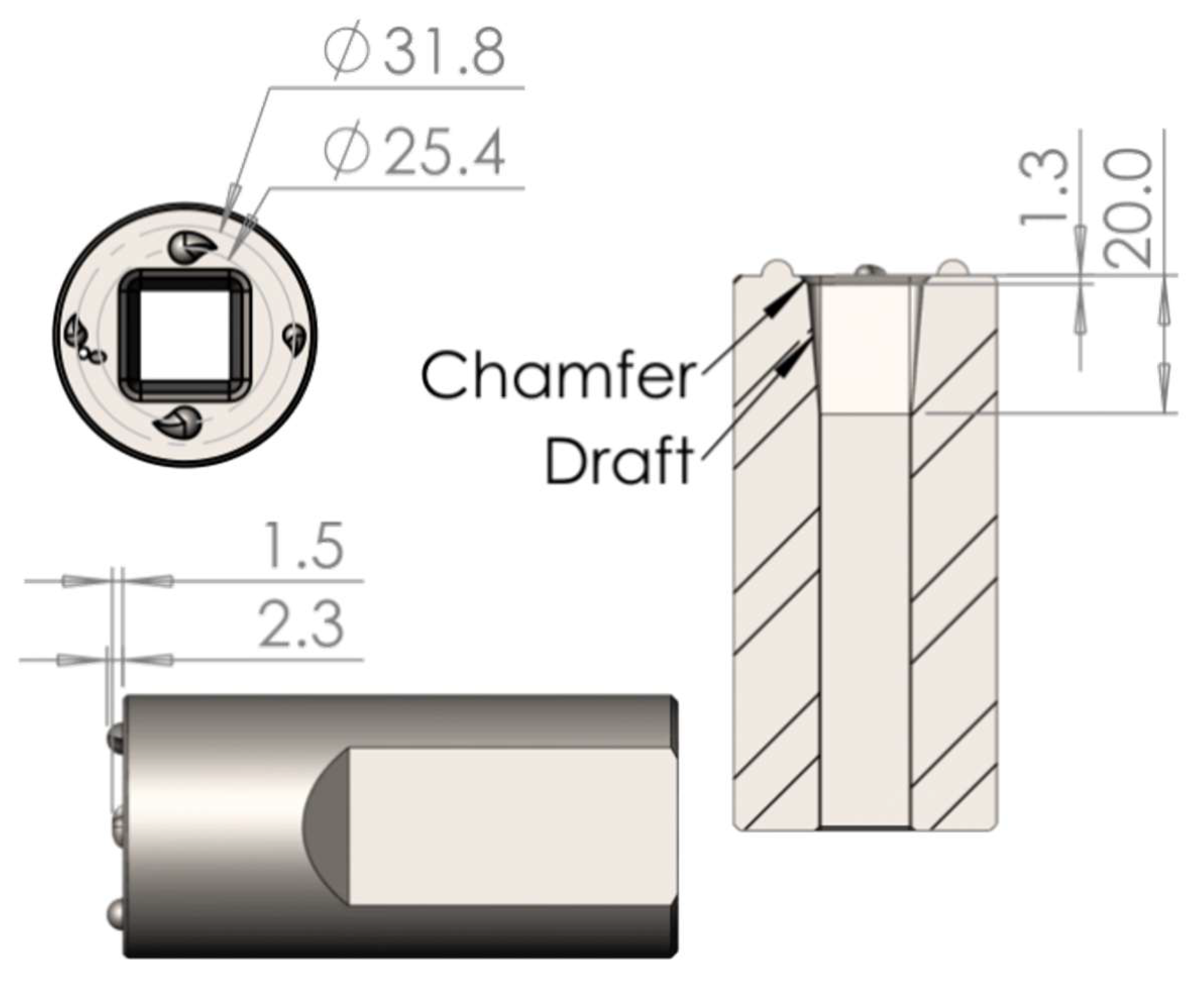
Figure 2.
Cooling system configurations with coolant shown in purple. (a & b) MELD tool holder with MELD tool signified in green. (a) ~36.5 mm of tool below water jacket. (b) ~12.7 mm of tool below water jacket. (c & d) LCTH integrated system with two tools: orange and blue. (c) ~46.5 mm of tool below LCTH (d) ~12.7 mm of tool below LCTH.
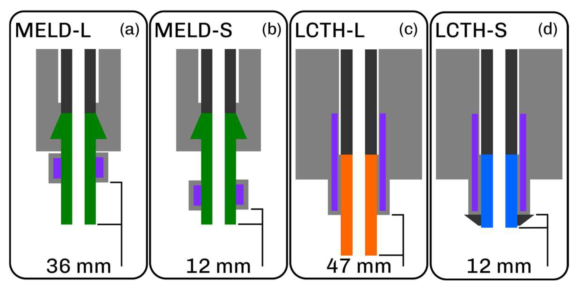
Figure 4.
Comparison of builds done with three cooling systems: No cooling (a), MELD cooling (b), and LCTH cooling (c).
Figure 4.
Comparison of builds done with three cooling systems: No cooling (a), MELD cooling (b), and LCTH cooling (c).
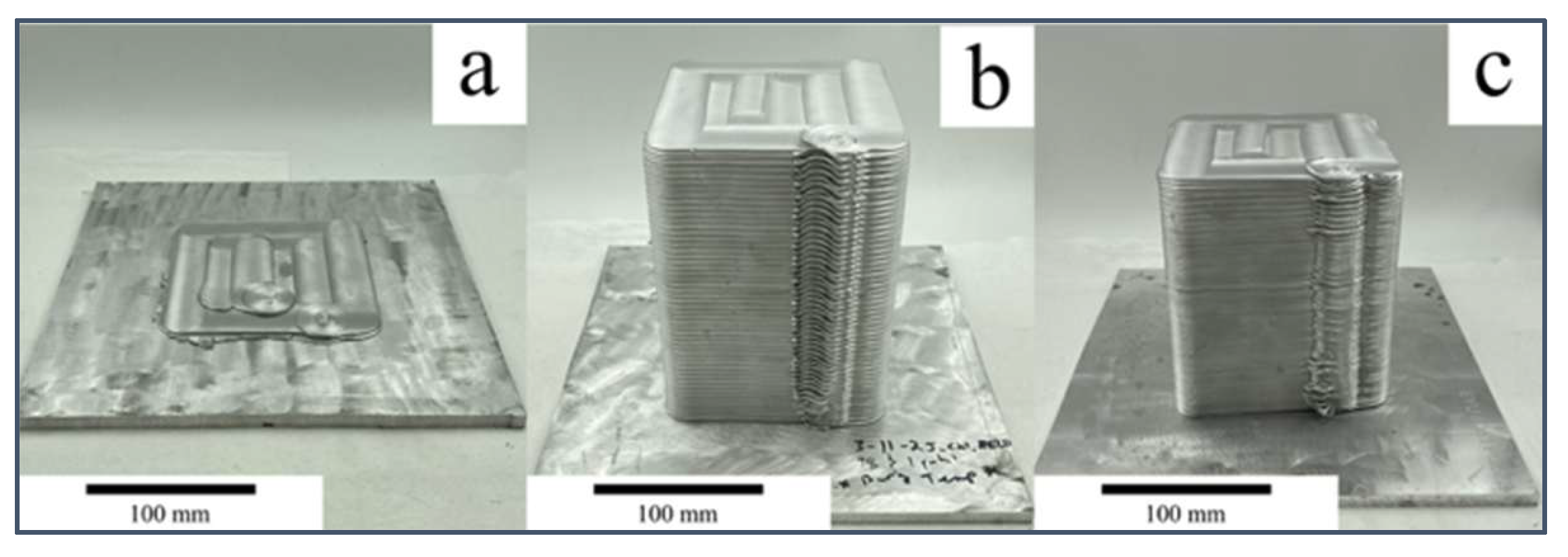
Figure 5.
Spindle bearing data from builds b and c from Figure 4, bearing temperatures at each deposited layer.
Figure 5.
Spindle bearing data from builds b and c from Figure 4, bearing temperatures at each deposited layer.
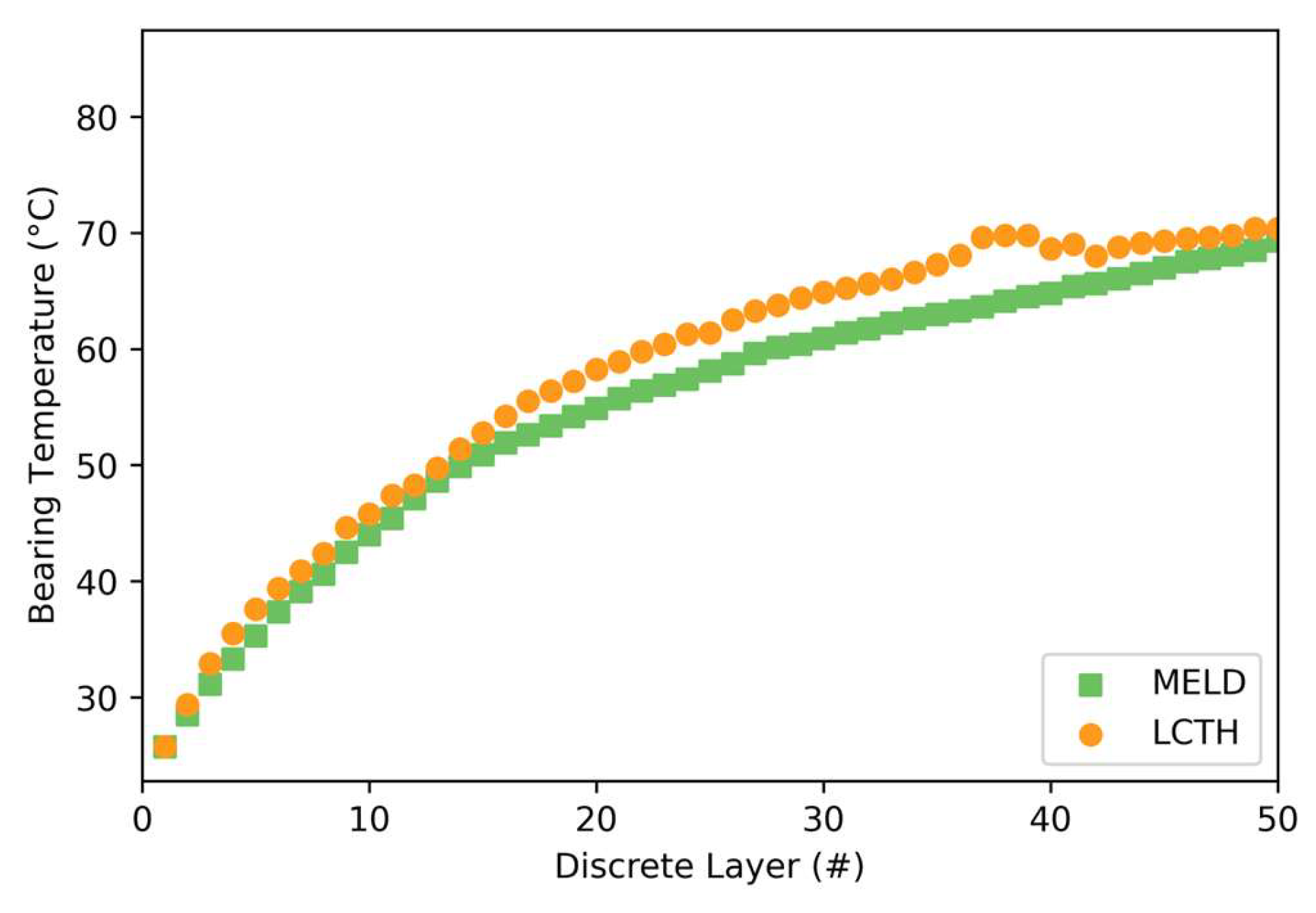
Figure 6.
Four configuration builds showing top surface and side quality being very similar between all. LCTH-S has degraded side quality, but this is believed to be due to the prototype collar used on tool that caused additional flashing.
Figure 6.
Four configuration builds showing top surface and side quality being very similar between all. LCTH-S has degraded side quality, but this is believed to be due to the prototype collar used on tool that caused additional flashing.
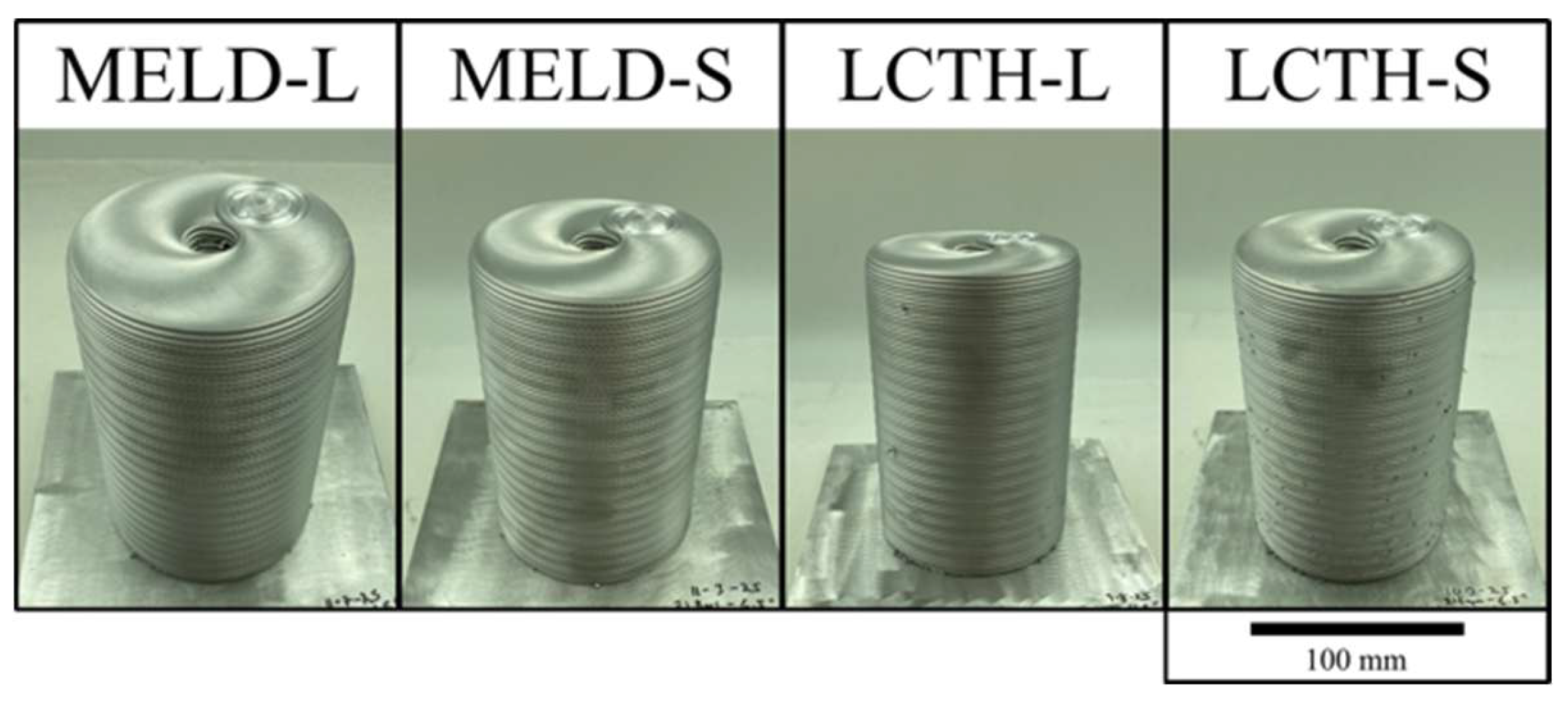
Figure 7.
(A) Tool temperature overtime during entire helical builds from each configuration. (B) Layer four layers (last bar) of each configuration during the helical builds.
Figure 7.
(A) Tool temperature overtime during entire helical builds from each configuration. (B) Layer four layers (last bar) of each configuration during the helical builds.
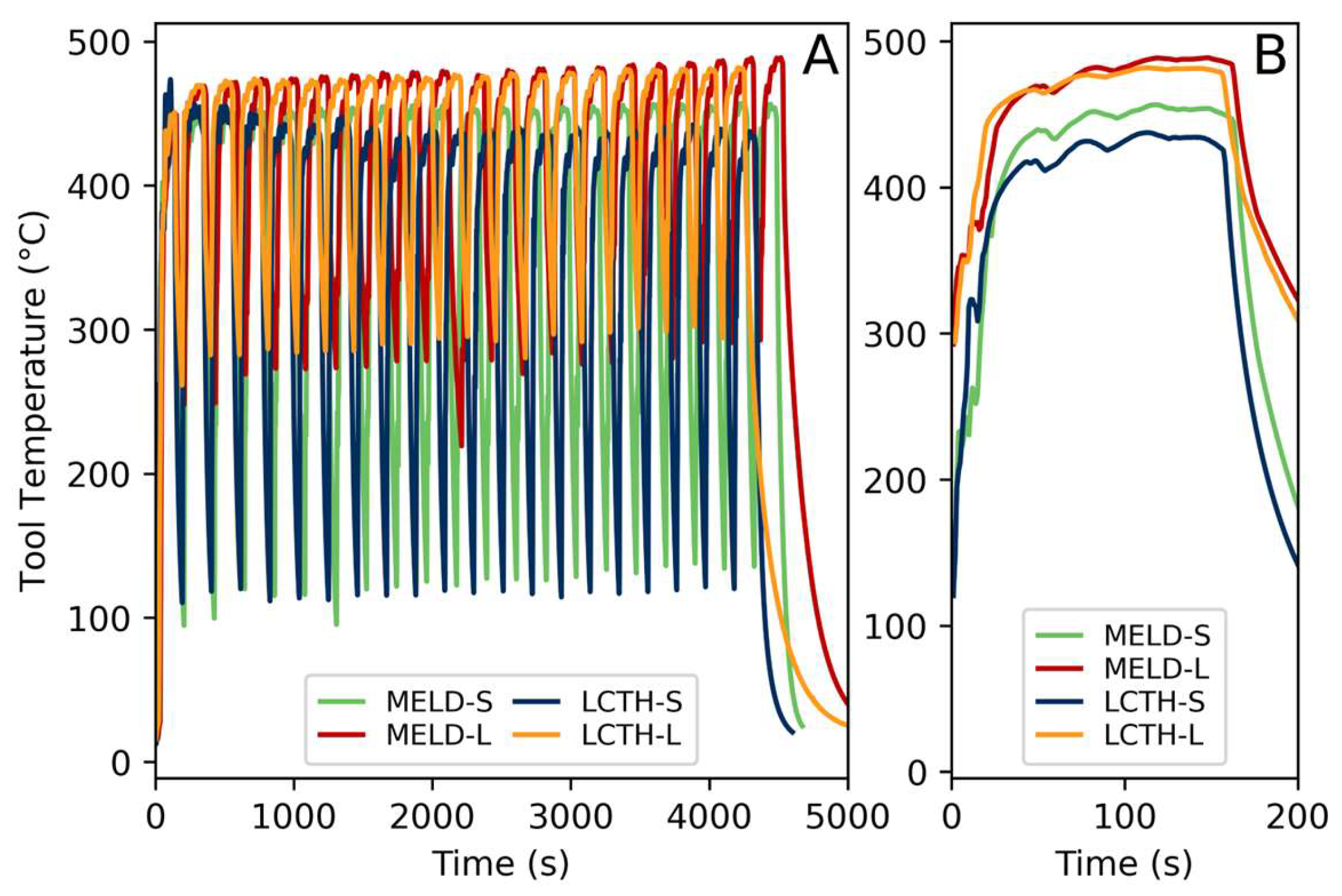
Figure 8.
Average Vickers hardness of five feed rods for each configuration. Hardness values along feed material starting at deposition end of feed rod.
Figure 8.
Average Vickers hardness of five feed rods for each configuration. Hardness values along feed material starting at deposition end of feed rod.
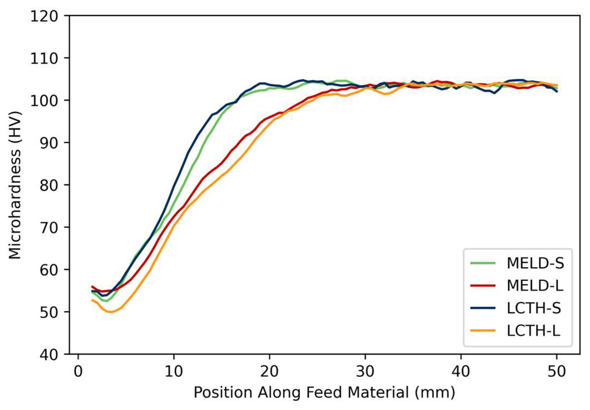
Figure 9.
Yield strength at various temperatures for AA6061-T651. Data for curve from Granta EduPack materials database [37].
Figure 9.
Yield strength at various temperatures for AA6061-T651. Data for curve from Granta EduPack materials database [37].
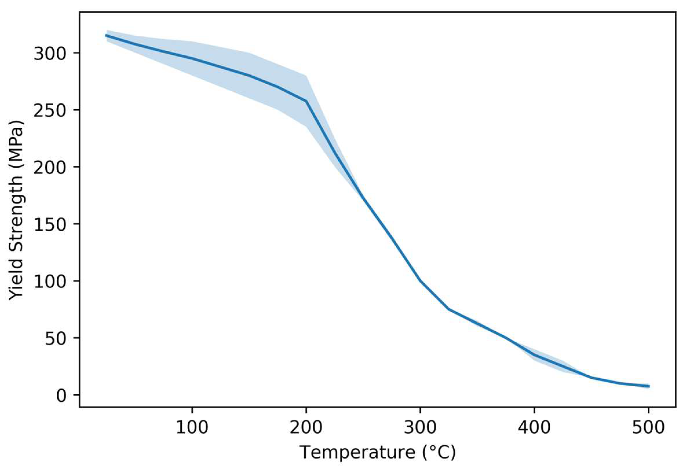
Figure 10.
Tool temperature for both LCTH and MELD cooling systems, being used on both discrete and continuous MELD AFSD machines. [green and dark blue are from the discrete machine L3 and purple and light blue are from continuous machine CD-14].
Figure 10.
Tool temperature for both LCTH and MELD cooling systems, being used on both discrete and continuous MELD AFSD machines. [green and dark blue are from the discrete machine L3 and purple and light blue are from continuous machine CD-14].
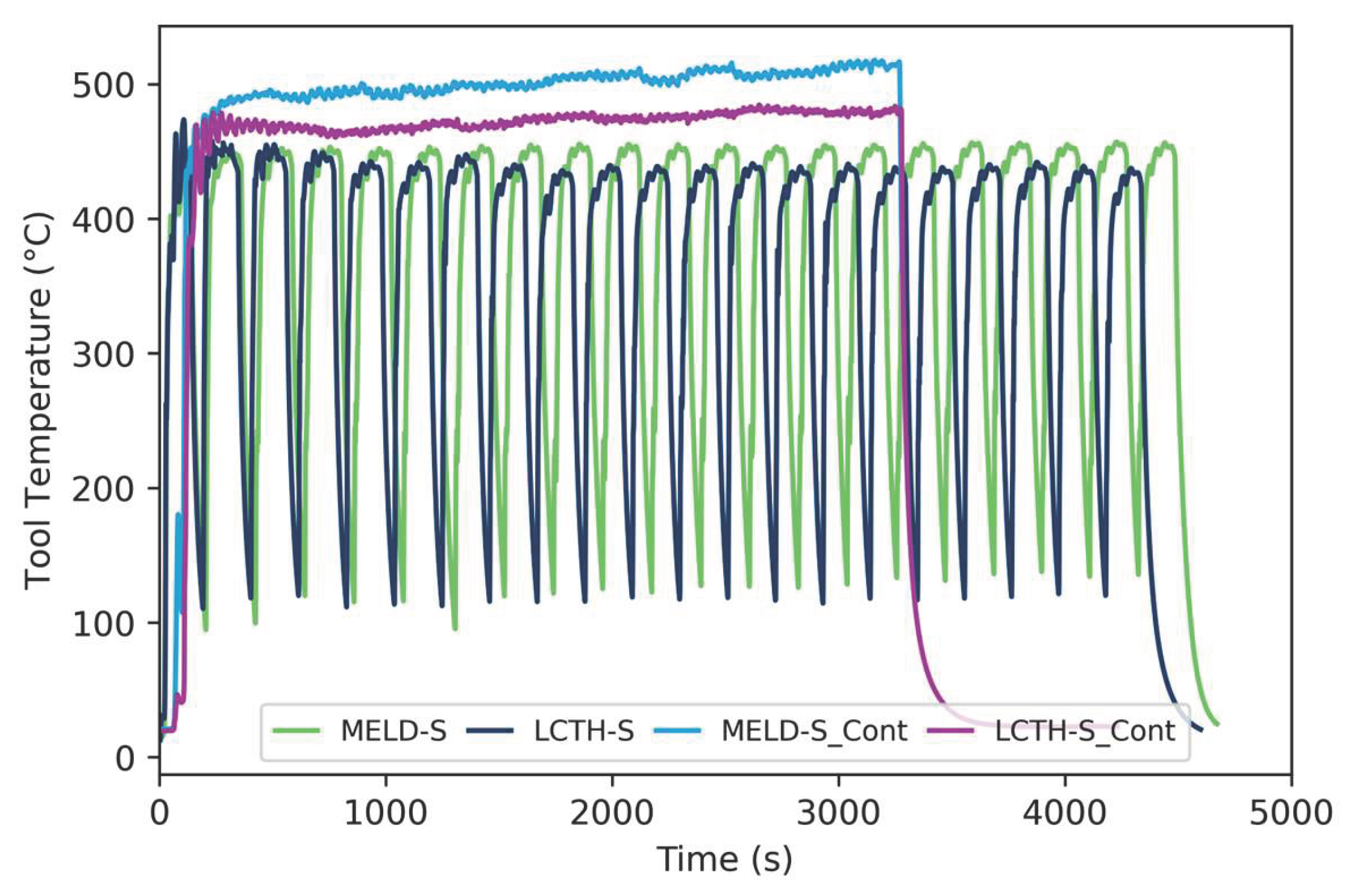

Table 1.
cooling system comparison.
| Systems | Flow Style | Cooling Style | Cooling Area (mm2) | Flow Rate (L/min) |
|---|---|---|---|---|
| MELD | Vacuum (pull) | Direct | ~2,000 | ~8.0 |
| LCTH | Pressure (push) | Indirect | ~8,000* | ~12.0 |
| ~15,000** | ||||
| * LCTH to Tool ** Coolant to LCTH |
||||
Table 2.
Chemical composition of 6061 material for feed material and substrates [34].
Table 2.
Chemical composition of 6061 material for feed material and substrates [34].
| Component, Wt. % | Al | Cr | Cu | Fe | Mg | Mn | Si | Ti | Zn |
|---|---|---|---|---|---|---|---|---|---|
| AA 6061-T6 | Bal. | 0.04-0.35 | 0.15-0.4 | Max 0.7 | 0.8-1.2 | Max 0.15 | 0.4-0.8 | Max 0.15 | Max 0.25 |
Disclaimer/Publisher’s Note: The statements, opinions and data contained in all publications are solely those of the individual author(s) and contributor(s) and not of MDPI and/or the editor(s). MDPI and/or the editor(s) disclaim responsibility for any injury to people or property resulting from any ideas, methods, instructions or products referred to in the content. |
© 2026 by the authors. Licensee MDPI, Basel, Switzerland. This article is an open access article distributed under the terms and conditions of the Creative Commons Attribution (CC BY) license (http://creativecommons.org/licenses/by/4.0/).
Copyright: This open access article is published under a Creative Commons CC BY 4.0 license, which permit the free download, distribution, and reuse, provided that the author and preprint are cited in any reuse.


