
Submitted:
14 February 2026
Posted:
27 February 2026
You are already at the latest version
Abstract
Due to faster charging, longer charge–discharge cycles, and broader operating temperature ranges, electrochemical supercapacitors (ES’s) can be used in electric vehicles, electronic devices, and smart grids. NiCo2O4@CC and NiCo2S4@CC composites were synthesized using a two-step hydrothermal method without organic binders on a carbon cloth substrate. NiCo2O4@CC was successfully synthesized through a hydrothermal reaction at 160 °C for 16 h and annealing at 350 °C for 2 h. NiCo2S4@CC was successfully synthesized through a hydrothermal reaction at 160 °C for 16 h, followed by a reaction at 120 °C for 14 h and annealing at 350 °C for 2 h. Annealing was found to make the structure of the loaded compound more stable, which was beneficial in preventing shedding of the active substance. The synergistic effect between polymetals, nanoparticles, porosity and high conductivity of carbon cloth improved the electrochemical performance. The specific capacitance of the NiCo2S4@CC sample at the current density of 1 A/g was about 1.5 times that of the NiCo2O4@CC sample. The electrolyte entered the voids due to the irregular arrangement of needle-like NiCo2S4, which enlarged the contact area between the ions in the solution and NiCo2S4@CC, resulting in an increase in the specific capacitance. A preferred irregular arrangement of nanostructure, sulphur substitution for oxygen atom, and the formation of more active sites can be assumed to be the underlying mechanism. The high flexibility of NiCo2S4@CC enables it to be further used to provide a stable power supply for wearable and portable electronic devices.
Keywords:
supercapacitors
; hydrothermal synthesis
; NiCo₂O₄@CC
; NiCo₂S₄@CC
; carbon cloth
; electrochemical active sites
1. Introduction
The electrochemical supercapacitors (ESs) utilize high surface area electrode materials and thin electrolytic dielectrics to achieve capacitance several orders of magnitude larger than conventional capacitors [1]. ESs offer the fast charging–discharging capacities and higher energy storage density than conventional capacitors [2]. Supercapacitors can be divided into three categories [3,4] depending on the energy storage mechanism: electrical double-layer capacitors (EDLCs) [5], pseudocapacitors [6], and hybrid supercapacitors [7]. The ESs exhibit several advantages over electrochemical batteries and fuel cells [8,9], including (1) attain higher energy densities while still maintaining the characteristic high power density of conventional capacitors (increase in both capacitance and energy). (2) Maintaining low Equivalent Series Resistance (ESR) characteristic of conventional capacitors and achieving comparable power densities. (3) Fast charging, long charge–discharge cycles, and broad operating temperature ranges. With these advantages, ESs have found wide applications in hybrid or electric vehicles, wearable electronics, aircrafts, and smart grids [10].
Compared with fuel cells and lithium ion batteries, the insufficient energy density is the major shortcoming for ESs [4,11,12]. Developing new electrode materials is one of the most effective ways to overcome this shortcoming. Electrode materials can contain carbon materials [13,14,15], conductive polymers [16,17,18], metal compounds [19,20], and composite materials [21,22]. Carbon cloth (CC) is used as the electrode material of flexible supercapacitors to be applied to portable and wearable products, offering the advantages of light weight, low cost, excellent flexibility, large surface area, high conductivity, and good conductivity [23,24,25,26,27].
Various methods have been reported for the synthesis of electrode materials based on CC [28,29,30,31]. Ghosh et al. [32] used flexible carbon fiber (CF) cloth as substrate for the hydrothermal growth of nickel hydroxide and cobalt hydroxyl carbonate and developed a flexible supercapacitor electrode. The as-fabricated flexible supercapacitors CF–Ni(OH)2//CF–CNT and CF–Co(OH)xCO3//CF–CNT were able to deliver high specific energy at high specific power accompanied by an excellent cycle stability. Horng et al. [33] fabricated nano-sized polyaniline nanowires on CC (PANI-NWs/CC) via an electrochemical method; the nanowire not only increased the specific capacitance to 1220 F g−1, but also alleviated cycling degradation issues caused by a mechanical issue. Sekhar et al. [34] proposed to grow binder-free nickel-cobalt layered double hydroxide nanosheets on Ag NWs-fenced carbon cloth (NC LDH NSs@Ag@CC). They also fabricated Ni-Co LDH-ZnO nanowires on CC [35] and exhibited the advantages of metal nanowires in producing a high areal capacitance and a good cycling stability. The commonly used synthesis methods included hydrothermal, electrochemical anodization, one-step etching & doping (E&D), dipping, electrochemical polymerization, CBD, and electrochemical deposition [36,37,38,39,40]. The hydrothermal method has the characteristics of simplicity, environmental friendliness, and uniform growth of the load. Our hypothesis was that hydrothermal method could synthesize nanoneedles and tree-like, nanoflower shape, ultrathin nanosheets, tectorum-like, for a high surface area and porous, shorten ion and electron transport paths, and could increase active sites for Faradaic capacitance reactions.
The purpose of this study is to synthesize NiCo2O4 nanoparticles and NiCo2S4 nanoneedles on carbon cloth by a hydrothermal method using nickel-cobalt oxides as precursors without a binder, and to investigate the influence of the nickel-cobalt oxides and sulphur substitution on the microstructure, morphology, and electrochemical properties of the NiCo2O4@CC and NiCo2S4@CC.
2. Materials and Methods
2.1. Materials
NiCl2·6H2O, CoCl2·6H2O, CH4N2O, Na2S·9H2O were purchased from Titan (China). HNO3, CH3CH2OH, 2-MI, KOH were purchased from Sinopharm (China). Carbon cloth (CC) with a dimension of 32×16 cm2 was obtained from Shanghai Jingchong (China). All the chemicals were used as received without further purification.
2.2. Synthesis of NiCo2O4@CC
A 2×2 cm2 carbon cloth was cleaned in the HNO3 solution, ethanol and deionized water respectively for 25 min in an ultrasonic bath to remove surface oxides. Subsequently, the carbon cloth in the Petri dish was dried in the convection oven at 75°C.
The NiCo2O4@CC was prepared by the hydrothermal method: 0.12 g NiCl2·6H2O, 0.27 g CoCl2·6H2O, 0.3 g urea and 0.6 g 2-MI were dissolved and uniformly dispersed for 15 min in the ultrasonic bath. The above pink solution and carbon cloth were transferred to 100 mL Teflon-lined stainless steel autoclave for hydrothermal reaction: heated to 160 °C and held for 16 h before cooling to room temperature in the furnace. Loose Ni-Co precursor on the surface was removed by cleaning in the ethanol and deionized water in the ultrasonic bath, and further dried at 70 °C. The as-prepared Ni-Co precursor/CC was put in the crucible and then annealed at 350 °C for 2 h with a heating rate of 5 °C∙min-1 under N2 atmosphere in a muffle furnace. The NiCo2O4 was thus synthesized.
2.3. Synthesis of NiCo2S4@CC
The Ni-Co-O@CC precursor was prepared according to the same method and procedures as before: The molar ratio of NiCl2·6H2O and CoCl2·6H2O and urea is 1:2:1. After the precursor was ultrasonic treatment and dried, the Ni-Co-O@CC precursor, 1.2 g Na2S·9H2O and 20 mL deionized water were transferred to 100 mL Teflon-lined stainless steel autoclave and maintained at 120 °C for 14 h. The Teflon-lined stainless steel autoclave was naturally cooled down to room temperature. Loose, unstable precursor was removed from the surface via cleaning in the ethanol and deionized water in the ultrasonic bath and further dried at 70 °C. The as-prepared Ni-Co-S@CC precursor was annealed at 350 °C for 2 h with a heating rate of 2 °C∙min-1 under N2 atmosphere in a muffle furnace. The flowchart for the preparation of NiCo2S4@CC was shown in Figure 1.
2.4. Characterization of Materials
X-ray diffraction (XRD) patterns were obtained using an X'Pert PRO X-ray diffractometer (PANalytical B.V., Netherlands) with a Cu Kα radiation at a scanning rate of 2°/min. A field emission scanning electron microscope (SEM) characterization was carried out on Merlin Compact (Carl Zeiss NTS GmbH, Jena, Germany). A transmission electron microscope (TEM), HRTEM and SAED measurements were recorded by JEM-2100 (JEOL, Tokyo, Japan). X-ray Photoelectron Spectrometer (XPS) was obtained by ESCALAB 250 (Thermo-VG Scientific). The Raman spectrum of specimen was measured using LabRAM HR Evolution (Horiba Scientific, France), which was carried out at room temperature with laser excitation source of 633nm and a light spot size of 0.5mm.
Electrochemical measurements were performed by CHI660D electrochemical workstation (Chenhua, Shanghai, China) using a three-electrode system. The Hg/HgO, graphite rod, and the prepared samples are respectively used as reference electrode, counter electrode, and working electrodes with 2.0 M KOH electrolyte solution.
The electrochemical properties of as-prepared materials were examined by cyclic voltammetry (CV), galvanostatic charge-discharge (GCD) and electrochemical impedance spectroscopy (EIS). CV curves can be divided into two situations: the double-layer CV response of pure CC electrode materials and Faraday pseudocapacitor CV curves of sample in the potential window of -0.2-0.6 V at different scan rates of 1, 2, 5, 10, 20 and 50 mV·s-1. The recorded GCD V-t curves exhibit a symmetrical triangular shape of sample at different current densities and distinct discharge platform (the Faraday reaction process of the pseudocapacitive electrode material). The better the symmetry of the curve, the better the reversibility of the material. The specific capacitances calculated from the discharge curves are determined by using the rules as stated below:
where C (F·g-1) is the specific capacitance of the mass of sample. I (A) is the current during discharge process. ∆t (s) is the discharge time. ∆V (V) is the potential window, and m (g) is the mass of sample.
EIS measurements were conducted in the frequency ranged from 100 kHz to 0.01 Hz, and the Nyquist plots were fitted by Zview software. As the Nyquist plots show, the semicircle part indicates that the Rct is caused by the charge transfer phenomenon of the active ions in the electrolyte during the reaction, and the linear part Rs corresponds to the ion diffusion resistance in the solution.
3. Results and Discussion
The nanostructure design of ESs is regarded as an effective approach to improve the electrochemical performance. Figure 2a shows the XRD patterns of the synthesized NiCo2O4@CC. The patterns of cubic NiCo2O4 phase were detected, which exhibited three strong lines and broad half peaks at the diffraction angle of 36.58°, 43.2°, and 45.05°. A comparison with the standard NiCo2O4 PDF card (JCPDS 73-1702) indicated that the crystal lattice planes (111), (220), (311), (222), (400), (511), and (440) were present in the samples. NiCo2O4 structure and carbon cloth were the confirmed phases in the sample.
Raman spectroscopy further characterizes the molecular structure of NiCo2O4@CC. In the Raman spectra (Figure 2b), three CC characteristic Raman band-D, band-G, and band-G0 appeared at 1350 cm-1, 1589 cm-1, and 2698 cm-1, respectively. The corresponding peaks were due to defect (D) and Graphite (G and G0).
Three typical Raman peaks were also observed at 457 cm-1, 478 cm-1, 650 cm-1, and the NiCo2O4 vibration modes corresponding to these peaks were Eg, E2g, and A1g, respectively. Which indicated that the phase transitions had occurred during the hydrothermal process. The Raman peak Eg near 550 cm-1 exhibited the formation of NiCoxO4 with high Ni content and incomplete phase transition, “x” indicating non-stoichiometric Co concentration. E2g, and A1g also indicated that carbon has a highly defective disordered structure, and these surface defects are conducive to the growth and precipitation of NiCo2O4.
Micrographs of NiCo2O4 on the surface of CC at different magnifications are illustrated in Figure 3a-c. NiCo2O4 sheet (TEM image in Figure 3d) was shown to have been made of nanoparticles with a diameter of approximate 10 nm (red dot circle in Figure 3e). The calculated d-spacing 2.8 Å and 4.6 Å (Figure 3f) confirmed the (220) and (111) lattice plane of NiCo2O4. As shown in Figure 3b, the agglomeration occurred on the surface of NiCo2O4 sheets, possibly activated by the excessive surface energy of the nanoparticles. As a substrate, carbon cloth could effectively avoid agglomeration caused by nanoparticles [41]. The subsequent annealing process refined the synthesized NiCo2O4 nanoparticles, distributed them more evenly, and increased the toughness of the sheets. Annealing was suggested as beneficial for applying NiCo2O4@CC to energy storage devices of various shapes.
Pure carbon cloth is a typical EDLC. The CV curves of CC working electrode in 2 M KOH electrolyte solution (Figure 4a) exhibits obvious rectangular shape at different scanning rates when the working voltage is set at the range of -0.2 to 0.6V. The area of the rectangle increases with the increased scanning speed. In contrast, a pair of obvious symmetric REDOX peaks can be observed in the CV curves of NiCo2O4@CC samples (Figure 4b) when the scanning rates are at 5 mV/s, 10 mV/s, 20 mV/s, and 50 mV/s, respectively, indicating that the prepared samples have the characteristics of REDOX pseudocapacity. With the increase of the scanning rate, the REDOX peaks switch slightly to both sides, but the shape does not change dramatically. However, an excessive increase of scanning rate will lead to the occurrence of polarization phenomenon, which will make it difficult for REDOX to occur41. In the GCD test, the curves of NiCo2O4@CC (Figure 4c) at different current densities of 1 A/ g, 2 A/g, 5 A/g, 8 A/g, and 10 A/g show a good symmetry. The results also indicate that the charging and discharging time has decreased with the increasing current densities. So, the area enclosed by the curves and the horizontal axis gradually has decreased, indicating that the specific capacitance of NiCo2O4@CC samples is proportional to the charging time. At the current density of 1 A/g, the specific capacitance of NiCo2O4@CC samples is 661.48 F/g (Figure 4c,d shows that the specific capacitance decreases with the increasing current densities, which agrees with the GCD experiments.
The EIS of NiCo2O4@CC at the frequency range from 0.01 Hz and 100 kHz were also investigated. Figure 5a shows the impedance spectrum obtained after data processing. After the circuit fitting analysis, the RS and RCT were calculated to be 1.20 Ω and 5.48 Ω, respectively. The small RS indicates that the electrode has smaller diffusion resistance and higher conductivity. The charge transfer phenomenon of active ions in the electrolyte has occurred during the reaction process, which leads to the produce of RCT.
The cycling performance of NiCo2O4@CC is shown in Figure 5b. At the current density of 10 A/g, the sample was tested for 3500 cycles of charge and discharge. In the first 300 cycles, the specific capacitance has decreased significantly, which may be caused by shedding of the NiCo2O4 grown on the surface of the CC. After 3500 cycles, the specific capacitance has remained at 78.89%.
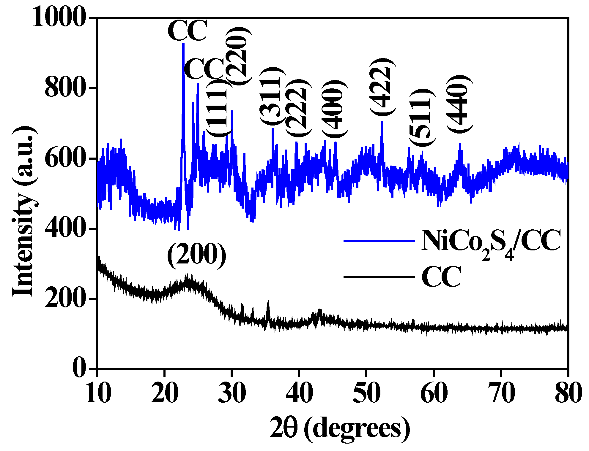
XRD results of NiCo2S4@CC samples are shown in Fig. 6. Diffraction peaks of CC (JCPDS 47-0787) are observed at 20.57°, 24.13°, and 25.14°. And the patterns of NiCo2S4 exhibited three strong lines and diffraction peaks at the 2 angle of 31.2°, 36.8°, 38.6°, 44.8°, 55.7°, 59.4°, and 65.2°. A comparison with the standard NiCo2S4 PDF card (JCPDS 73-1704) 42 indicated that planes (220), (311), (222), (400), (422), (511), and (440) of NiCo2S4 are present with the samples.
Figure 6.
X-rays diffraction patterns of NiCo2S4@CC.
SEM images in Figure 7a-c show that needle-like NiCo2S4 on CC. The region, as marked by the square in Figure 7a, is magnified in Figure 7b, which is consisted of acicular needles. The NiCo2S4 needles in Figure 7c themselves are made of assembled nanoparticles. NiCo2S4 was observed to grow on CC uniformly and irregularly, forming the tunnel gap structure with different sizes, which is beneficial to increase the contact area between electrolyte and active substance and shorten the diffusion path of ion. Such structural characteristics are conducive to improving the capacitance of electrode materials. EDS spectrum of NiCo2S4@CC also proved that sulphur atoms successfully replace oxygen atoms to synthesize NiCo2S4, and the elemental ratio obtained also agreed with the chemical stoichiometry. The bright-field TEM images in Figure 7d-f show the microstructure and morphology of the tip of acicular NiCo2S4. The region, as marked by the square in Figure 7d, is magnified as Figure 7e. The further high-resolution TEM image shows that the NiCo2S4 needle is consisted of nanoparticle domains, with crystal planes having a calculated d-spacing 2.362 Å, 2.681 Å, and 3.581 Å (Figure 7f). These d-spacing results indicate that crystal planes are (400), (222), and (220).
A selected region of the Raman spectra of NiCo2S4@CC is shown in Figure 8a. The extension of sulphur atoms to tetrahedral nickel atom sites and the bending of S-Nietra-S bond led to the response of A 1g (391 cm-1) mode and Eg (204 cm-1) mode. The 627 cm-1 and 504 cm-1 at the Raman peak represent T 2g and A 1g modes respectively, and the asymmetric bending of the S-Nitetra-S bond results in three T 2g modes at around 187cm-1, 317 cm-1, and 352 cm-1. which is consistent with the results from the literature [42].
The surface valence states, molecular structure, and atom ratios of NiCo2S4@CC were evaluated by X-ray photoelectron spectroscopy (XPS). Figure 8b shows the XPS results on NiCo2S4@CC. From the graph, the elements of carbon, nickel, cobalt, and sulphur can be easily identified through the characteristic peaks of C1s, Ni2p, Co2p, and S2s (S2p). The oxygen peak O1s is due to the influence of oxygen in the air during the XPS measurement. XPS spectrum of elements C, Ni, Co, and S are shown in Figure 8c-f. Two obvious spin-orbit double peaks and oscillating satellite peaks are shown in Figure 8c, which correspond to Ni 2p1/2 and Ni 2p3/2 electron orbits at the peaks of 856.34 eV, 873.76 eV (Ni3+) and 854.87 eV and 871.56 eV (Ni2+), respectively. Figure 8d shows the Co 2p3/2, Co 2p1/2 electron orbits of Co3+ (binding energies 781.71 eV and 797.29 eV) and Co2+ (binding energies 777.85 eV and 795.57 eV). In addition, the S 2p3/2, S 2p1/2 electron orbits of S (binding energies 161.8eV and 163.6eV) are measured as shown in Figure 8e. At the binding energies of 283.81 eV and 284.96 eV (Figure 8f), C-C and C-O peaks are observed, which are attributed to the carbon cloth. It can be concluded that there are oxidation states of Ni2+, Ni3+, Co2+, Co3+, and S2+ in the samples.
As shown in Figure 9a, the CV curves of NiCo2S4@CC working electrode in 2 M KOH electrolyte solution exhibits a pair of symmetrical REDOX peaks, at different scanning rates -5 mV/s, 10 mV/s, 20 mV/s, 30 mV/s, and 50 mV/s, when the working voltage is set at the range of -0.2 to 0.6V, which proves the pseudocapacitive behavior. With the increase of the scanning rate, the peaks shift to both sides.
There is a small protrusion beside the oxidation peak. It is possible that there are two REDOX pairs in the REDOX process. Maybe more electrolyte solution penetrates into the needle structure of the electrode material with the increased time, and more sites are activated. With the increase of scanning rate, the area surrounded by CV curve gradually increases, indicating that the specific capacitance of the electrode material increases accordingly. This phenomenon can also be explained by the diffusion of OH-1 in the electrolyte solution. The diffusion rate of OH-1 speeds up with the increase of scanning rate. The NiCo2S4@CC sample exhibited more active REDOX reactions.
The specific capacitance of the electrode material is further demonstrated by the GCD experiments shown in Figure 9b. The GCD curve exhibits excellent symmetry and has a unique platform of pseudocapacitive materials. Compared with NiCo2O4@CC electrode materials, NiCo2S4@CC electrode materials have a better symmetry and stability. After calculation, the NiCo2S4@CC electrode materials exhibits a specific capacitance of 858 F/g at a current density of 1 A/g. When the current density gradually increases, the REDOX process did not take place completely and the specific capacitance of the sample also decreased. The platform shown in the GCD curve is derived from , Faraday REDOX process of NiCo2S4 in KOH electrolyte solution [42]:
The EIS of NiCo2S4@CC electrode and NiCo2O4@CC electrode were tested with the above parameters, and the EIS map and fitting circuit were illustrated in Figure 10. The Rct and Rs were 1.0 Ω and 1.6 Ω respectively, which were smaller than those of NiCo2O4@CC. This indicates that NiCo2S4@CC has higher electrical conductivity, and the needle-like structure is conductive to the diffusion of active substances and a faster charge movement. The acicular structure of NiCo2S4@CC effectively reduces the ion diffusion resistance and electron transport impedance of the system and increased the performance of supercapacitors.
Specific capacitance of NiCo2S4@CC samples at different current densities is shown in Figure 11a. The specific capacitance gradually decreases with the increasing current density. Because the ions in electrolyte solution do not react completely with the active substance of electrode material due to the increase of current, the active site and response time for Faraday REDOX reaction has been reduced. In order to understand the stability of NiCo2S4@CC samples, a charging-discharge experiment was conducted on 3500 cycles of GCD at a current density of 10 A/g, as shown in Figure 11b. It was found that the specific capacitance of the sample did not decrease gradually all the time, but showed a slight increase at about 50 cycles. It suggested more active substances in the NiCo2S4@CC sample were activated, leading to a small increase in the specific capacitance. After 1000 cycles, the specific capacitance of the sample decreased, which may be caused by the loose and detached parts of the active substances loaded on the surface of the CC.
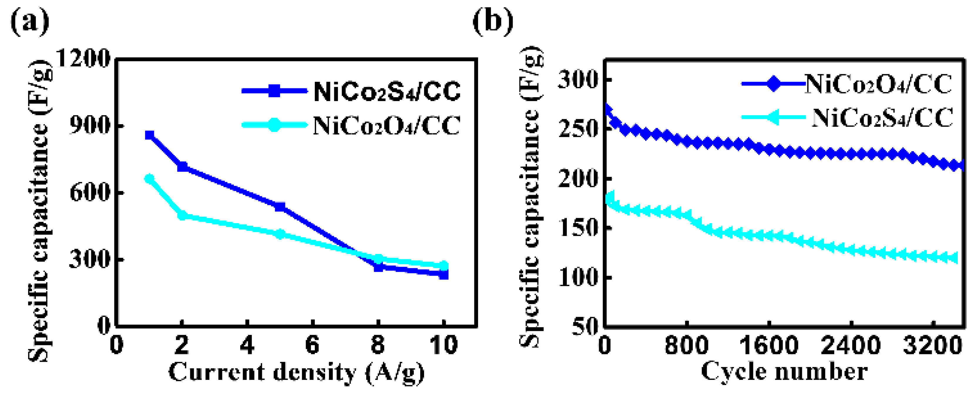
It was found that the specific capacitances of the NiCo2O4@CC and NiCo2S4@CC samples decreased with the increasing current density. As shown in Figure 12, at a low current density, the specific capacitance of NiCo2S4@CC (with a needle-like structure) was higher than that of NiCo2O4@CC (with a granular structure). These results indicate that NiCo2S4@CC exhibits superior pseudocapacitive performance. However, at high current densities, the specific capacitance of NiCo2S4@CC was slightly lower than that of NiCo2O4@CC, this is because the gap channels formed by the irregular needle-like structures are longer, preventing the electrolyte solution from fully contacting more active sites. In contrast to NiCo2O4@CC (Figure 5b), NiCo2S4@CC (Figure 11b) demonstrates better electrochemical stability. Both samples experienced different degrees of specific capacitance loss.
Needle-like NiCo2S4@CC was synthesized by replacing oxygen with sulphur in NiCo2O4. The structure has a larger surface area than nano-granular NiCo2O4, and the needle-like structures are randomly arranged, creating many voids. Such a structure may allow the electrolyte to penetrate more easily into the deeper surfaces of the active material, thereby exposing more active sites. Sulfides may offer a larger surface area, good ionic conductivity, and the ability to accommodate various atoms and ions within their structure.
4. Conclusions
A flexible pseudocapacitive electrode material of NiCo2S4@CC was successfully prepared via a hydrothermal method, which exhibits the advantages of high flexibility, excellent electrical conductivity, and low cost.
NiCo2O4 sheets composed of nanoparticles were synthesized on the surface of CC by the hydrothermal method, which effectively alleviated the agglomeration phenomenon caused by the large specific surface area of the nanoparticles. The subsequent annealing process further enhanced the structural toughness and stability of the material. The results indicated that the specific capacitance of the NiCo2S4@CC sample at a current density of 1 A·g⁻¹ is approximately 1.5 times that of the NiCo2O4@CC sample.
The NiCo2S4@CC sample possesses a nanoneedle-like structure with abundant pores, which effectively shortens the ion and electron transport paths during the electrochemical reaction and thus improves the capacitance performance of the sample. Flexible supercapacitors assembled with NiCo2S4@CC based on flexible CC electrode materials are expected to exhibit competitive advantages in applications for wearable and portable electronic devices.
Author Contributions
Conceptualization, S.S., X.W., L.L., and P.X.; data curation, X.W. and S.S.; methodology, L.L and P.X.; investigation, S.S. and X.W.; formal analysis, X.W.; funding acquisition, P.X.; writing—original draft preparation, X.W., S.S.; writing—review and editing, L.L. and P.X.; supervision, P.X.; project administration, S.S.; funding acquisition, P.X. resources, S.S., X.W., L.L., and P.X. All authors have read and agreed to the published version of the manuscript.
Funding
This research was funded by the Natural Science Foundation of Shanghai, grant number 20ZR1422700, Class III Peak Discipline of Shanghai—Materials Science and Engineering (High-Energy Beam Intelligent Processing and Green Manufacturing), and Special Fund for the Development of Doctoral Program in SUES.
Conflicts of Interest
The authors declare no conflicts of interest.
References
- Conway, B.E. Elements of Electrostatics Involved in Treatment of Double Layers and Ions at Capacitor Electrode Interphases. In Electrochemical supercapacitors: Scientific fundamentals and technological applications; Kluwer Academic/Plenum Press: New York, NY, USA, 1999; Volume 4, pp. 67–68. [Google Scholar]
- Lv, H.; Pan, Q.; Song, Y.; Liu, X.-X.; Liu, T. A Review on Nano-/Microstructured Materials Constructed by Electrochemical Technologies for Supercapacitors. Nano-Micro Lett. 2020, 12, 1–56. [Google Scholar] [CrossRef] [PubMed]
- Zaharaddeen, S. Iro.; Subramani, C.; S.S. A brief review on electrode materials for supercapacitor. Int. J. Electrochem. Sci 2016, 11, 10628–10643. [Google Scholar]
- Zhong, C.; Deng, Y. D.; Hu, W. B.; Qiao, J. L.; Zhang, L.; Zhang, J. J. A review of electrode materials and compositions for electrochemical supercapacitors. Chem. Soc. Rev 2015, 44, 7484–7539. [Google Scholar] [CrossRef]
- Bothe, A.; Pourhosseini, S.; Ratajczak, P.; Beguin, F.; Balducci, A. Towards understanding the impact of operating voltage on the stability of adiponitrile-based electrical double-layer capacitors. J. Power Sources 2021, 496. [Google Scholar] [CrossRef]
- Eskandari, M.; Malekfar, R.; Buceta, D.; Taboada, P. NiCo2O4-based nanostructured composites for high-performance pseudocapacitor electrodes. Colloids Surfaces A: Physicochem. Eng. Asp. 2020, 584. [Google Scholar] [CrossRef]
- Sun, P.; Zhang, J.; Huang, J.; Wang, L.; Wang, P.; Cai, C.; Lu, M.; Yao, Z.; Yang, Y. Bimetallic MOF-derived (CuCo)Se nanoparticles embedded in nitrogen-doped carbon framework with boosted electrochemical performance for hybrid supercapacitor. Mater. Res. Bull. 2021, 137. [Google Scholar] [CrossRef]
- Kötz, R.; Carlen, M. Principles and applications of electrochemical capacitors. Electrochim. Acta 2000, 45, 2483–2498. [Google Scholar] [CrossRef]
- Halper, M. S.; Ellenbogen, J. C. Supercapacitors: A Brief Overview; The MITRE Corporation: McLean, Virginia, USA, 2006; pp. 10–12. [Google Scholar]
- Kim, B. K.; Sy, S.; Yu, A. P.; Zhang, J. J. Handbook of Clean Energy Systems; John Wiley & Sons Press: Hoboken, New Jersey, USA, 2015; pp. 21–25. [Google Scholar]
- Wang, Y.; Diaz, D.F.R.; Chen, K.S.; Wang, Z.; Adroher, X.C. Materials, technological status, and fundamentals of PEM fuel cells—A review. Mater. Today 2020, 32, 178–203. [Google Scholar] [CrossRef]
- Sun, J.; Xu, C.; Chen, H. A review on the synthesis of CuCo2O4-based electrode materials and their applications in supercapacitors. J. Materiomics 2021, 7, 98–126. [Google Scholar] [CrossRef]
- Fischer, U.; Saliger, R.; Bock, V.; Petricevic, R.; Fricke, J. Carbon Aerogels as Electrode Material in Supercapacitors. J. Porous Mater. 1997, 4, 281–285. [Google Scholar] [CrossRef]
- Liu, C. F.; Liu, Y. C.; Yi, T. Y.; Hu, C. C. Carbon materials for high-voltage supercapacitors. Carbon 2019, 145, 529–548. [Google Scholar] [CrossRef]
- Jain, A.; Ghosh, M.; Krajewski, M.; Kurungot, S.; Michalska, M. Biomass-derived activated carbon material from native European deciduous trees as an inexpensive and sustainable energy material for supercapacitor application. J. Energy Storage 2021, 34. [Google Scholar] [CrossRef]
- Shirakawa, H.; Louis, E.J.; MacDiarmid, A.G.; Chiang, C.K.; Heeger, A.J. Synthesis of electrically conducting organic polymers: halogen derivatives of polyacetylene, (CH) x. J. Chem. Soc. Chem. Commun. 1977, 578–580. [Google Scholar] [CrossRef]
- MacDiarmid, A.G.; Mammone, R.J.; Kaner, R.B.; Porter, L.; Porter, S.J.; Pethig, R.; Heeger, A.J.; Rosseinsky, D.R. The concept of ‘doping’ of conducting polymers: the role of reduction potentials. Philos. Trans. R. Soc. London. Ser. A, Math. Phys. Sci. 1985, 314, 3–15. [Google Scholar] [CrossRef]
- Balint, R.; Cassidy, N.J.; Cartmell, S.H. Conductive polymers: Towards a smart biomaterial for tissue engineering. Acta Biomater. 2014, 10, 2341–2353. [Google Scholar] [CrossRef] [PubMed]
- Liu, R.; Zhou, A.; Zhang, X.; Mu, J.; Che, H.; Wang, Y.; Wang, T.-T.; Zhang, Z.; Kou, Z. Fundamentals, advances and challenges of transition metal compounds-based supercapacitors. Chem. Eng. J. 2021, 412. [Google Scholar] [CrossRef]
- Hassan, I.U.; Salim, H.; Naikoo, G.A.; Awan, T.; Dar, R.A.; Arshad, F.; Tabidi, M.A.; Das, R.; Ahmed, W.; Asiri, A.M.; et al. A review on recent advances in hierarchically porous metal and metal oxide nanostructures as electrode materials for supercapacitors and non-enzymatic glucose sensors. J. Saudi Chem. Soc. 2021, 25. [Google Scholar] [CrossRef]
- Lin, C.; Ritter, J.A.; Popov, B.N. Development of Carbon-Metal Oxide Supercapacitors from Sol-Gel Derived Carbon-Ruthenium Xerogels. J. Electrochem. Soc. 1999, 146, 3155–3160. [Google Scholar] [CrossRef]
- Zhang, X.; Li, Z.; Yu, Z.; Wei, L.; Guo, X. Mesoporous NiMoO4 microspheres decorated by Ag quantum dots as cathode material for asymmetric supercapacitors: Enhanced interfacial conductivity and capacitive storage. Appl. Surf. Sci. 2020, 505. [Google Scholar] [CrossRef]
- Ginting, R.T.; Ovhal, M.M.; Kang, J.-W. A novel design of hybrid transparent electrodes for high performance and ultra-flexible bifunctional electrochromic-supercapacitors. Nano Energy 2018, 53, 650–657. [Google Scholar] [CrossRef]
- Liu, X.Y.; Gao, Y.Q.; Yang, G.W. A flexible, transparent and super-long-life supercapacitor based on ultrafine Co3O4nanocrystal electrodes. Nanoscale 2016, 8, 4227–4235. [Google Scholar] [CrossRef]
- Shen, L.; Du, L.; Tan, S.; Zang, Z.; Zhao, C.; Mai, W. Flexible electrochromic supercapacitor hybrid electrodes based on tungsten oxide films and silver nanowires. Chem. Commun. 2016, 52, 6296–6299. [Google Scholar] [CrossRef] [PubMed]
- Sial, Q.A.; Javed, M.S.; Lee, Y.-J.; Duy, L.T.; Seo, H. Flexible and transparent graphene-based supercapacitors decorated with nanohybrid of tungsten oxide nanoflakes and nitrogen-doped-graphene quantum dots. Ceram. Int. 2020, 46, 23145–23154. [Google Scholar] [CrossRef]
- Barik, R.; Tanwar, V.; Kumar, R.; Ingole, P.P. A high energy density and high rate capability flexible supercapacitor based on electro-spun highly porous SnO2@carbon nanofibers. J. Mater. Chem. A 2020, 8, 15110–15121. [Google Scholar] [CrossRef]
- Rowlands, S.E.; Latham, R.J.; Schlindwein, W.S. Supercapacitor devices using porous silicon electrodes. Ionics 1999, 5, 144–149. [Google Scholar] [CrossRef]
- Dai, P.; Zhang, S.; Liu, H.; Yan, L.; Gu, X.; Li, L.; Liu, D.; Zhao, X. Cotton fabrics-derived flexible nitrogen-doped activated carbon cloth for high-performance supercapacitors in organic electrolyte. Electrochimica Acta 2020, 354. [Google Scholar] [CrossRef]
- Liu, T.; Zheng, Y.; Zhao, W.; Cui, L.; Liu, J. Uniform generation of NiCo2S4 with 3D honeycomb-like network structure on carbon cloth as advanced electrode materials for flexible supercapacitors. J. Colloid Interface Sci. 2019, 556, 743–752. [Google Scholar] [CrossRef]
- Zhao, W.; Zheng, Y.; Cui, L.; Jia, D.; Wei, D.; Zheng, R.; Barrow, C.; Yang, W.; Liu, J. MOF derived Ni-Co-S nanosheets on electrochemically activated carbon cloth via an etching/ion exchange method for wearable hybrid supercapacitors. Chem. Eng. J. 2019, 371, 461–469. [Google Scholar] [CrossRef]
- Ghosh, D.; Mandal, M.; Das, C.K. Solid State Flexible Asymmetric Supercapacitor Based on Carbon Fiber Supported Hierarchical Co(OH)xCO3 and Ni(OH)2. Langmuir 2015, 31, 7835–7843. [Google Scholar] [CrossRef]
- Horng, Y.-Y.; Lu, Y.-C.; Hsu, Y.-K.; Chen, C.-C.; Chen, L.-C.; Chen, K.-H. Flexible supercapacitor based on polyaniline nanowires/carbon cloth with both high gravimetric and area-normalized capacitance. J. Power Sources 2010, 195, 4418–4422. [Google Scholar] [CrossRef]
- Sekhar, S.C.; Nagaraju, G.; Yu, J.S. Conductive silver nanowires-fenced carbon cloth fibers-supported layered double hydroxide nanosheets as a flexible and binder-free electrode for high-performance asymmetric supercapacitors. Nano Energy 2017, 36, 58–67. [Google Scholar] [CrossRef]
- Shakir, I.; Shahid, M.; Rana, U.A.; Al Nashef, I.M.; Hussain, R. Nickel–Cobalt Layered Double Hydroxide Anchored Zinc Oxide Nanowires grown on Carbon Fiber Cloth for High-Performance Flexible Pseudocapacitive Energy Storage Devices. Electrochimica Acta 2014, 129, 28–32. [Google Scholar] [CrossRef]
- Liu, J.; Wang, Q.; Liu, P. Poly(1,5-diaminoanthraquinone) coated carbon cloth composites as flexible electrode with extraordinary cycling stability for symmetric solid-state supercapacitors. J. Colloid Interface Sci. 2019, 546, 60–69. [Google Scholar] [CrossRef]
- Zhang, R.; Liu, J.; Guo, H.; Tong, X. Hierarchically porous nickel oxide nanoflake arrays grown on carbon cloth by chemical bath deposition as superior flexible electrode for supercapacitors. Mater. Lett. 2014, 136, 198–201. [Google Scholar] [CrossRef]
- Liu, T.; Zheng, Y.; Zhao, W.; Cui, L.; Liu, J. Uniform generation of NiCo2S4 with 3D honeycomb-like network structure on carbon cloth as advanced electrode materials for flexible supercapacitors. J. Colloid Interface Sci. 2019, 556, 743–752. [Google Scholar] [CrossRef] [PubMed]
- Rowlands, S.E.; Latham, R.J.; Schlindwein, W.S. Supercapacitor devices using porous silicon electrodes. Ionics 1999, 5, 144–149. [Google Scholar] [CrossRef]
- Dai, P.; Zhang, S.; Liu, H.; Yan, L.; Gu, X.; Li, L.; Liu, D.; Zhao, X. Cotton fabrics-derived flexible nitrogen-doped activated carbon cloth for high-performance supercapacitors in organic electrolyte. Electrochimica Acta 2020, 354. [Google Scholar] [CrossRef]
- Wu, P.; Cheng, S.; Yao, M.; Yang, L.; Zhu, Y.; Liu, P.; Xing, O.; Zhou, J.; Wang, M.; Luo, H.; et al. A Low-Cost, Self-Standing NiCo2O4@CNT/CNT Multilayer Electrode for Flexible Asymmetric Solid-State Supercapacitors. Adv. Funct. Mater. 2017, 27. [Google Scholar] [CrossRef]
- Pu, J.; Cui, F.; Chu, S.; Wang, T.; Sheng, E.; Wang, Z. Preparation and Electrochemical Characterization of Hollow Hexagonal NiCo2S4 Nanoplates as Pseudocapacitor Materials. ACS Sustain. Chem. Eng. 2014, 2, 809–815. [Google Scholar] [CrossRef]
Figure 1.
Flowchart for the preparation of NiCo2S4@CC.
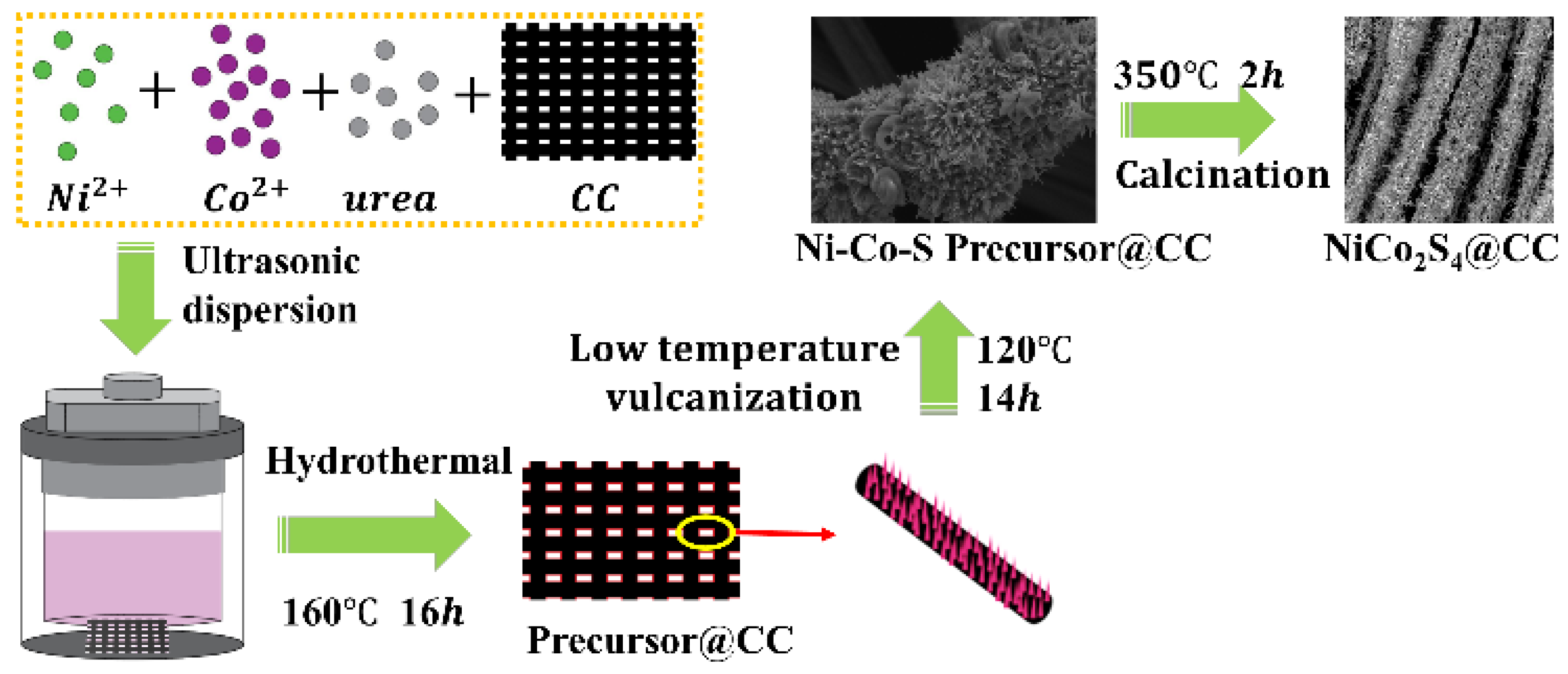
Figure 2.
(a) XRD trace and (b) Raman spectra of NiCo2O4@CC.
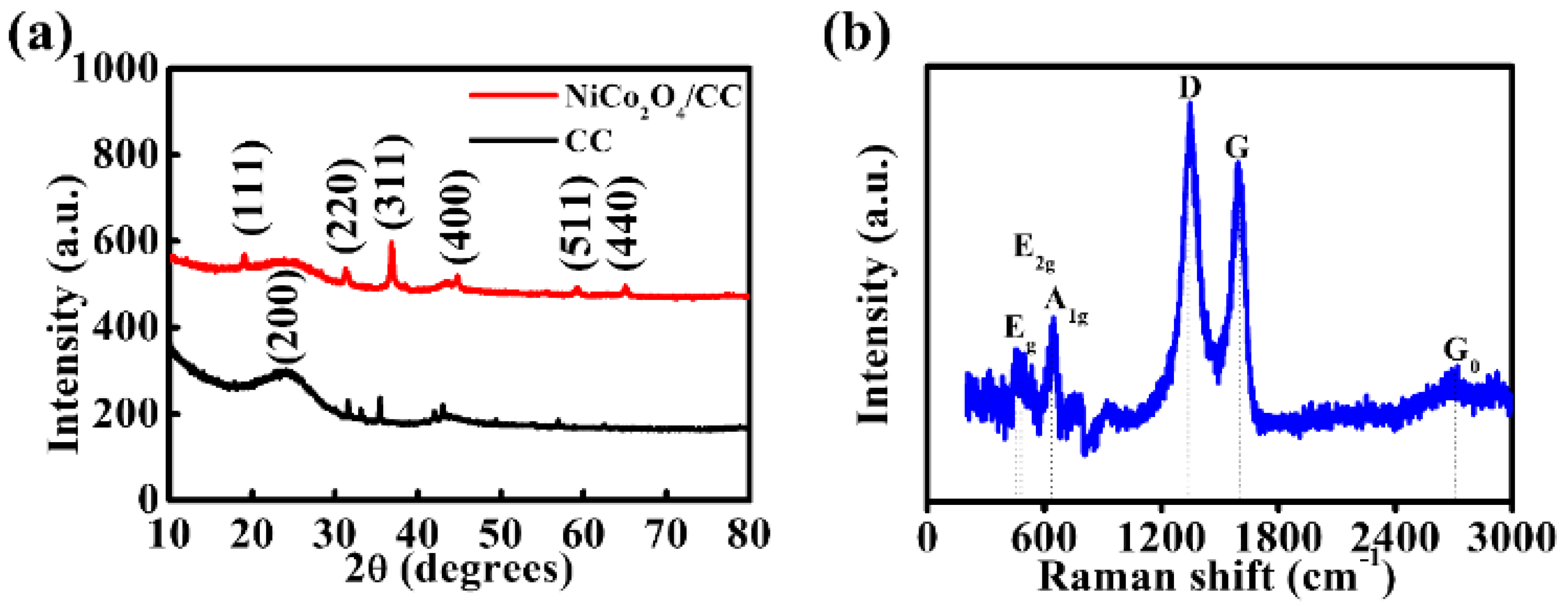
Figure 3.
(a) SEM images showing the NiCo2O4 sheet on the surface of CC. (b)-(c) The magnified SEM image of region “I” marked in Figure 3(a) showing the agglomeration (red circle) phenomenon. (d) Bright-field TEM images of NiCo2O4 sheet @CC and (e) region “II” marked in Fig. 3(d) showing the fine structure of assembled nanoparticles. (f) High-resolution TEM image showing the structures, crystal lattice, and the interface between the adjacent nanoparticles.
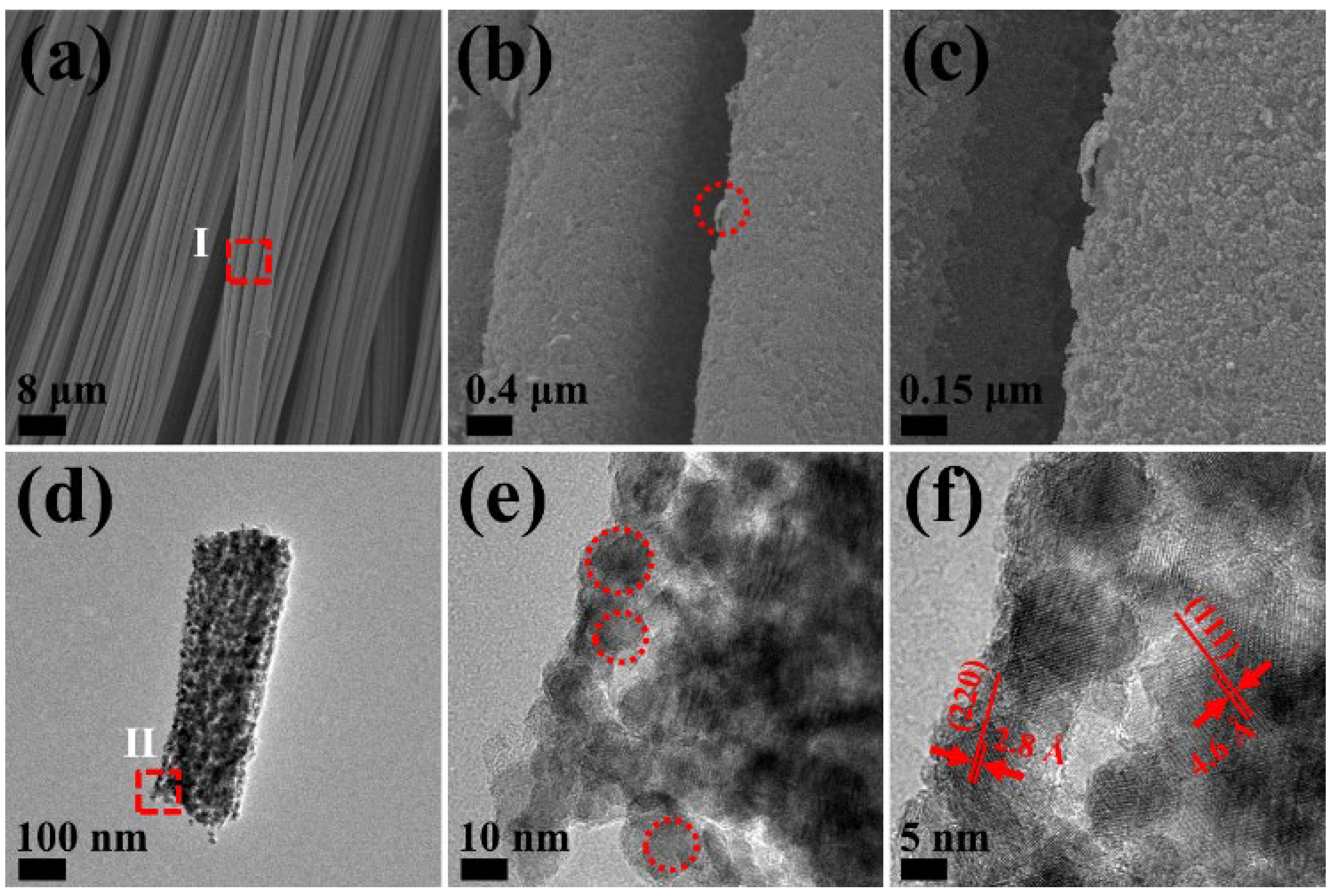
Figure 4.
Cyclic Voltammetry (CV) curves of (a) CC and (b) NiCo2O4@CC in 2 mol·L-1 KOH. (c) GCD curves of the NiCo2O4@CC at different current densities from 1 to 10 A·g-1. (d) The specific capacitances vs. current densities of NiCo2O4@CC.
Figure 4.
Cyclic Voltammetry (CV) curves of (a) CC and (b) NiCo2O4@CC in 2 mol·L-1 KOH. (c) GCD curves of the NiCo2O4@CC at different current densities from 1 to 10 A·g-1. (d) The specific capacitances vs. current densities of NiCo2O4@CC.
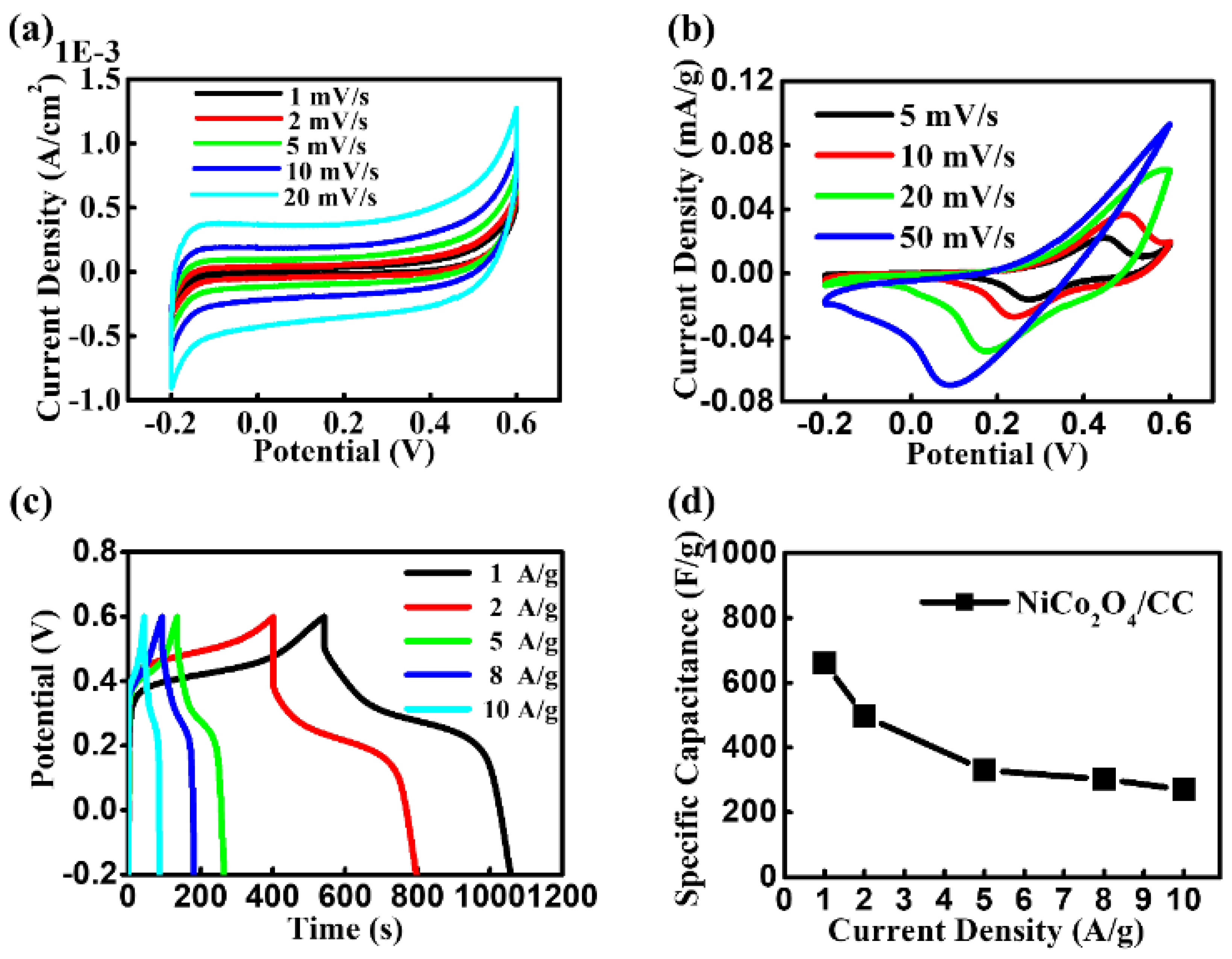
Figure 5.
(a) AC impedance of NiCo2O4@CC in 2 M KOH, and the inset of (a) is an equivalent circuit. (b) The cycling performance of NiCo2O4@CC.
Figure 5.
(a) AC impedance of NiCo2O4@CC in 2 M KOH, and the inset of (a) is an equivalent circuit. (b) The cycling performance of NiCo2O4@CC.
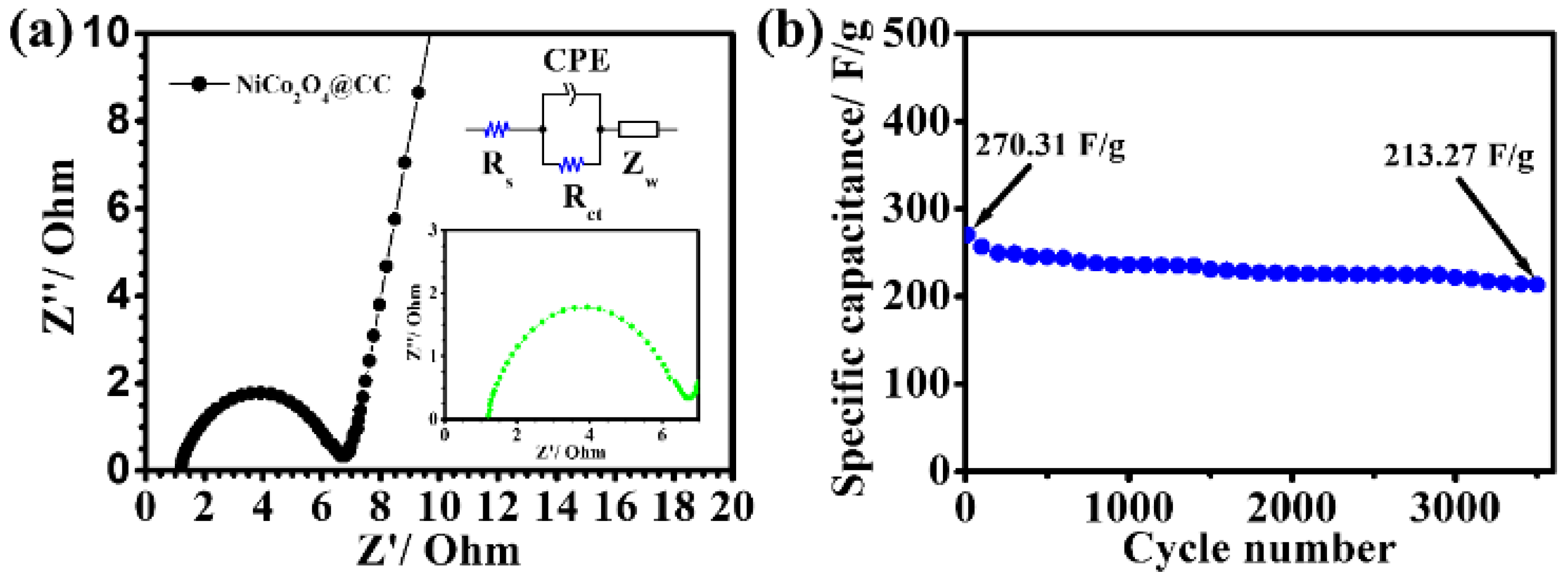
Figure 7.
(a, b, c) SEM images and (d, e, f) TEM image of NiCo2S4@CC at different magnifications.
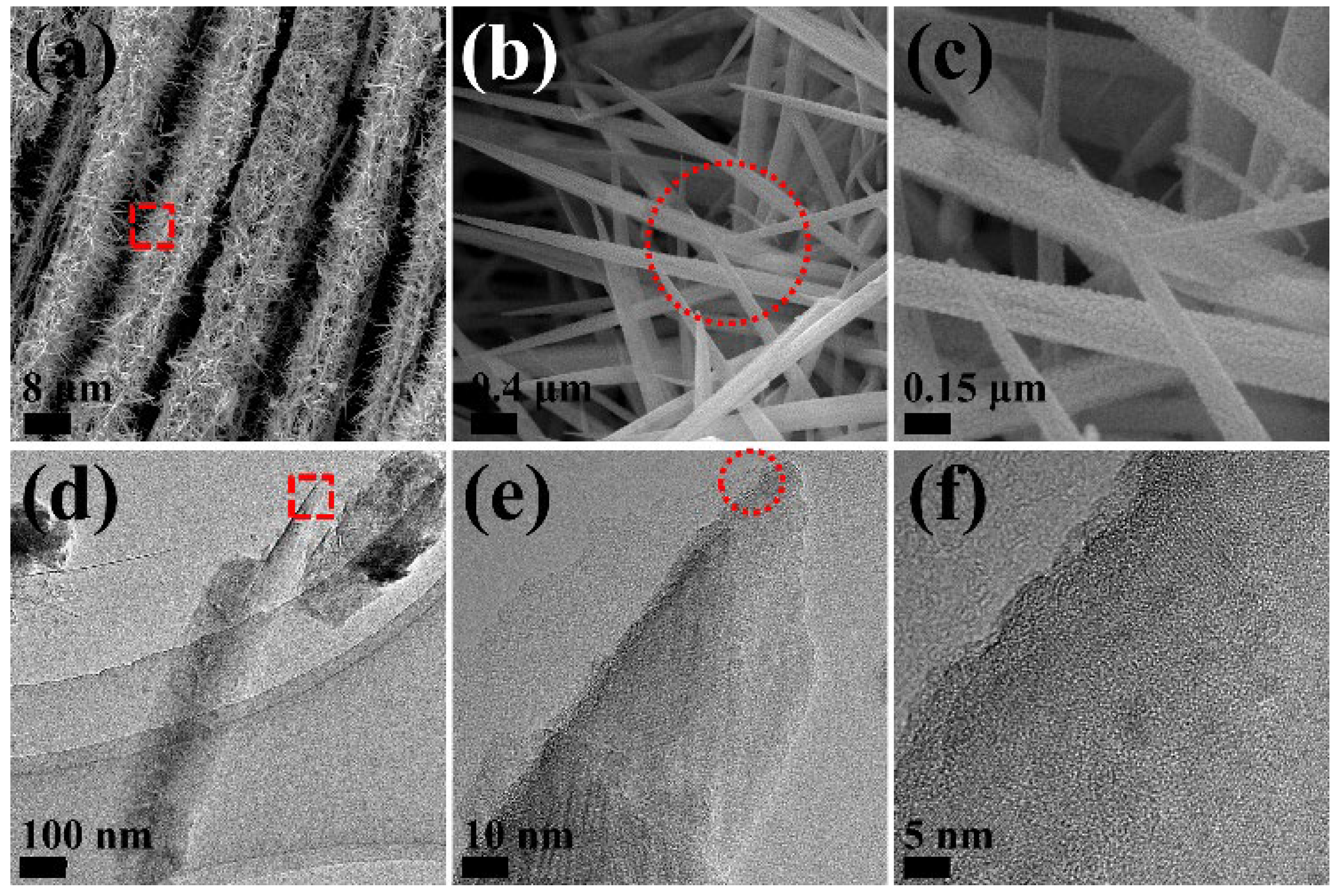
Figure 8.
(a) Raman spectra and XPS of (b) the full spectrum of the NiCo2S4@CC. (c) Ni 2p, (d) Co 2p, (e) S 2p and (f) C 1s spectra of NiCo2S4@CC composite fired in air.
Figure 8.
(a) Raman spectra and XPS of (b) the full spectrum of the NiCo2S4@CC. (c) Ni 2p, (d) Co 2p, (e) S 2p and (f) C 1s spectra of NiCo2S4@CC composite fired in air.
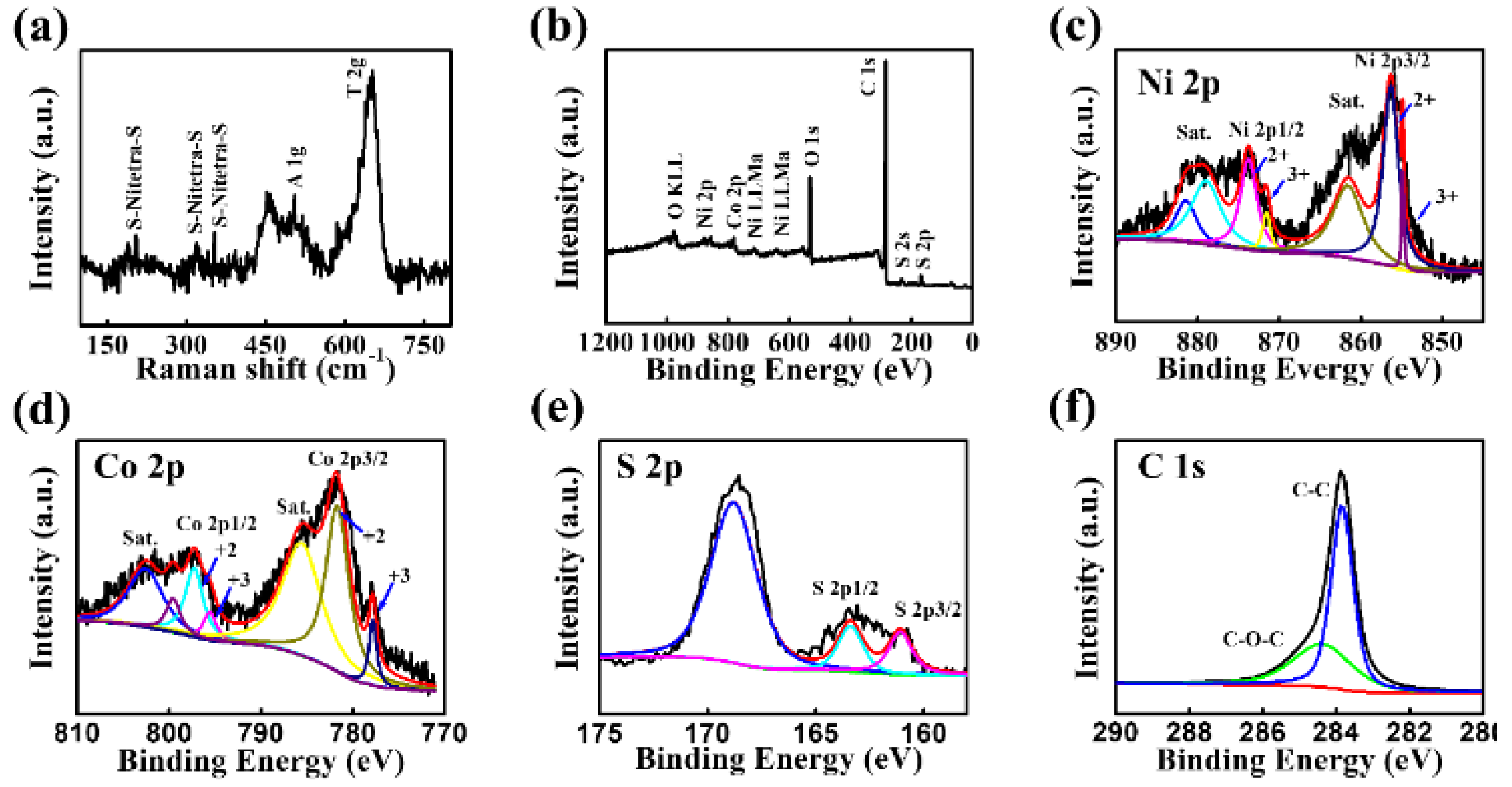
Figure 9.
(a) CV curves of the NiCo2S4@CC at different scan rates. (b) GCD curves of the NiCo2S4@CC at different current densities from 1 to 15 A/g.
Figure 9.
(a) CV curves of the NiCo2S4@CC at different scan rates. (b) GCD curves of the NiCo2S4@CC at different current densities from 1 to 15 A/g.
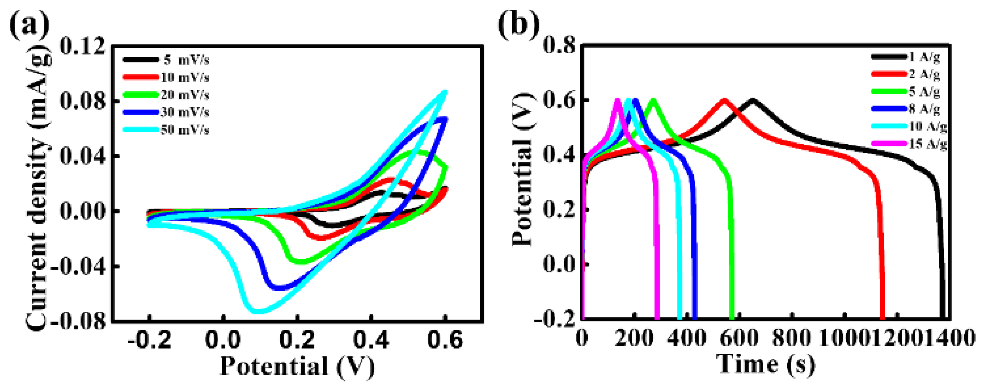
Figure 10.
The EIS curve of the NiCo2S4@CC, and the inset is an equivalent circuit.
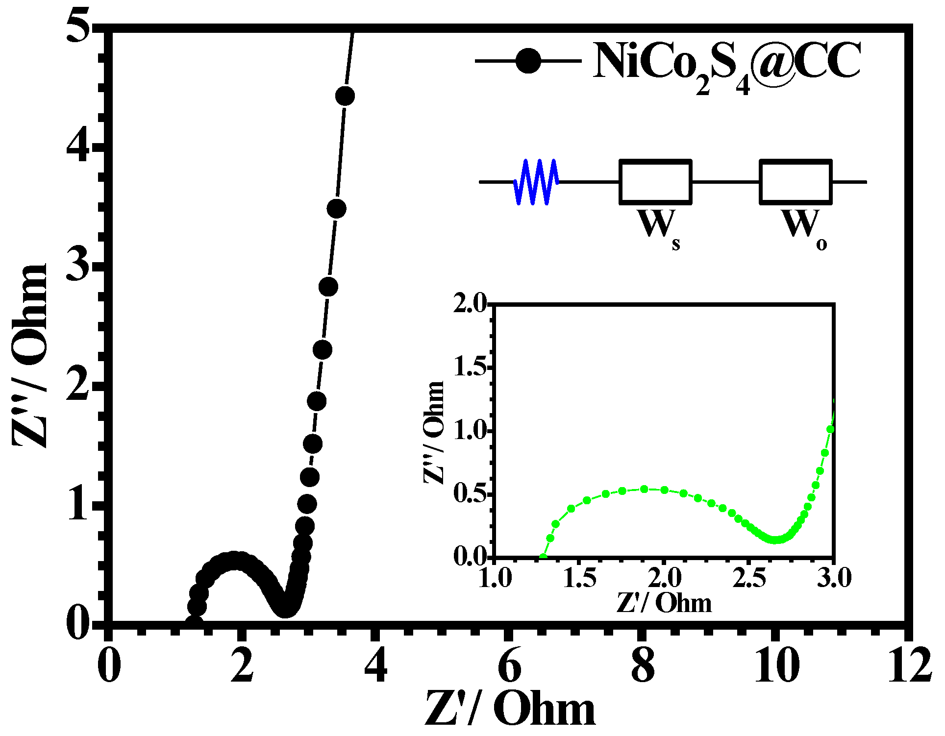
Figure 10.
(a) The specific capacitance at different current densities, and (b) the cycle stability at 10 A/g current density of NiCo2S4@CC.
Figure 10.
(a) The specific capacitance at different current densities, and (b) the cycle stability at 10 A/g current density of NiCo2S4@CC.
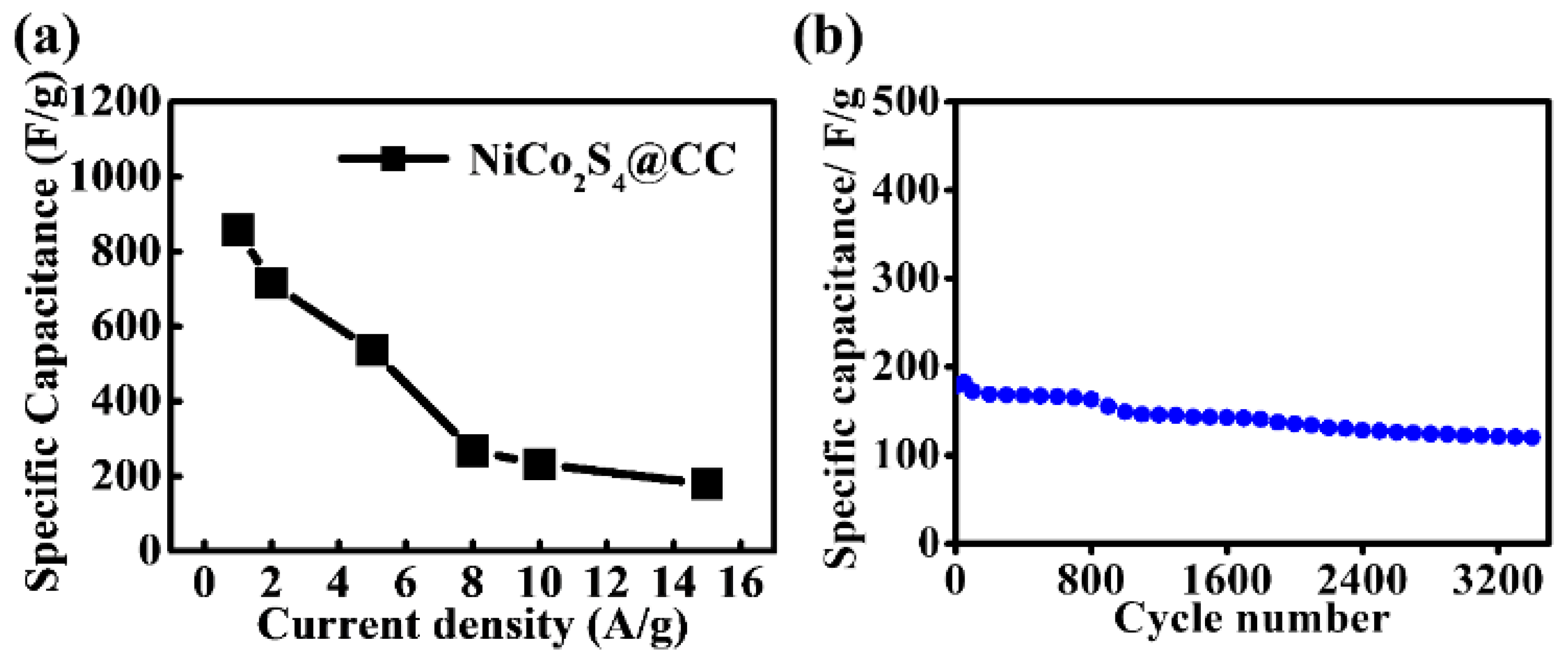
Figure 12.
(a) The specific capacitance comparison chart at different current densities and (b) the cycle stability comparison chart at 10 A/g current density between NiCo2S4@CC and NiCo2O4@CC.
Figure 12.
(a) The specific capacitance comparison chart at different current densities and (b) the cycle stability comparison chart at 10 A/g current density between NiCo2S4@CC and NiCo2O4@CC.
Disclaimer/Publisher’s Note: The statements, opinions and data contained in all publications are solely those of the individual author(s) and contributor(s) and not of MDPI and/or the editor(s). MDPI and/or the editor(s) disclaim responsibility for any injury to people or property resulting from any ideas, methods, instructions or products referred to in the content. |
© 2026 by the authors. Licensee MDPI, Basel, Switzerland. This article is an open access article distributed under the terms and conditions of the Creative Commons Attribution (CC BY) license (http://creativecommons.org/licenses/by/4.0/).
Copyright: This open access article is published under a Creative Commons CC BY 4.0 license, which permit the free download, distribution, and reuse, provided that the author and preprint are cited in any reuse.


