Submitted:
13 February 2026
Posted:
13 February 2026
You are already at the latest version
Abstract
The design, fabrication, and characterization of a highly transparent and flexible monopole antenna optimized for the 3–6 GHz frequency band is presented in this paper. In traditional Transparent Conductive Oxide (TCO) designs, there is always a trade-off between the RF efficiency and transparency. Therefore, an Aerosol Jet® 5X system was used to directly print a silver nanoparticle mesh over a 50-µm polyimide (PI) substrate. With this fabrication method, a durable structure was yield which works well both electrically and mechanically with 85% transparency and a gain of −2.5 dBi. In order to demonstrate how the antenna is flexible and compatible with other devices, it was bent over a cylindrical body and was integrated with a commercial solar panel. The results show that impedance matching and radiation characteristics of the antenna remain stable under bending conditions, and no critical decrease was observed in solar energy harvesting. Consequently, this design presents a suitable solution for energy-autonomous IoT systems, smart windows, and CubeSat applications.
Keywords:
transparent antenna
; metal mesh structure
; energy harvesting
; IoT applications
; wideband antenna
1. Introduction
As communication devices become more compact and effective, they require aesthetically unobtrusive antennas [1,2]. Transparent and flexible designs are a well-suited solution to this problem, since their structure is naturally low-profile. Therefore, they can be a good alternative for IoT devices, wearables, smart surfaces, and space-constrained CubeSat platforms [3,4].
In order to find a balance between optical transparency and RF performance, new material studies are undoubtedly necessary. While researchers have investigated various conductive materials, including Transparent Conductive Oxides (TCOs), silver nanowires (AgNWs), graphene, and Indium Tin Oxide (ITO), each suffers from inherent limitations [5,6,7]. Advanced fabrication techniques, such as Aerosol Jet printing and screen printing, have recently unlocked more precise patterning on flexible substrates. This precision is now redefining the limits of optical transparency [8,9].
Recent studies demonstrate transparent antennas operating with acceptable performance in the 2.4 GHz to sub-6 GHz bands [10,11]. Mid-band capabilities of 3-6 GHz are realized through circularly polarized designs [12], wideband fractal slots [13], transparent MIMO configurations [14], and dual-band transparent structures for Wi-Fi 6E [15].
Moreover, comprehensive reviews of flexible antennas indicate that material selection, mechanical robustness, and real-world integration strategies are critical for sub-6 GHz 5G applications [16,17,18]. Despite these advancements, it is still very challenging to achieve high transparency, flexibility, and reliable RF performance simultaneously in mid-band applications [19].
In order to bridge this gap, we present a transparent antenna designed for the 3-6 GHz range, fabricated using Aerosol Jet® 5X printing on a polyimide substrate. This method offers better mechanical flexibility and optical transparency compared to traditional approaches. Our experimental results show good agreement with simulations. Thus, the proposed design can be an ideal candidate for low-profile, surface-integrated communication systems.
The following is a summary of this study's contributions:
• Innovative Fabrication: Realizing a high-precision metal mesh with reliable RF performance and ~85% optical transparency through the use of Aerosol Jet® printing.
• Conformal Robustness: Verifying performance under bending conditions to demonstrate applicability for wearable applications.
• System-Level Integration: Demonstrating compatibility with self-powered IoT platforms, where the antenna shows negligible impact on the efficiency of commercial solar cells.
2. Antenna Configuration and Design Guidelines
To avoid the excessive simulation times associated with complex mesh geometries, we determined the antenna geometry (Figure 1) and design parameters (Table 1) using standard methodologies for fully metallic structures. A Coplanar Waveguide (CPW) feed was chosen to simplify the fabrication process, since the radiating element and ground plane are on the same substrate layer. Finally, a circular monopole configuration was selected to improve impedance bandwidth and ensure omnidirectional radiation.
A polyimide (, tan) substrate was used due to its availability, optical transparency, and flexibility. To use it in wearable applications, a thin substrate thickness of 50 μm was selected. We set the gap () to 0.20 mm and the signal line width () to 2.20 mm for achieving an impedance matching. An SMA connector was included in the simulation to improve the agreement between simulated and measured results.
3. Fabrication Process via Aerosol Jet Printing
An Aerosol Jet® 5X system (Figure 2a), which precisely deposits atomized conductive inks (silver nanoparticles) onto the substrate, was used for fabrication. With this method, it is possible to fabricate mesh structures ranging from micrometers to millimeters.
The manufactured prototype antenna is shown in Figure 2b, where the mesh line width is about 30 μm and the unit cell spacing is 250 μm. To ensure alignment and prevent short circuits on the slippery polyimide surface, the connector was bonded using silver adhesive and a custom mold. The gap between the signal line and ground planes was kept clear of silver adhesive to prevent impedance mismatch.
4. Experimental Validation and Discussion
4.1. Reflection Coefficient and Radiation Patterns
The reflection coefficient () of the antenna was obtained using a VNA, and the radiation pattern was measured in an anechoic chamber (Figure 3). The maximum realized gain of the antenna was -2.5 dBi.
Although the measurement and simulation results for agreed well (Figure 4), small deviations in the radiation pattern, specifically in the null regions at and (Figure 5a), were observed.
It is believed that these differences stem from the experimental setup. The metallic rotator and the relatively large SMA connector (compared to the 50 µm substrate) acted as reflectors and scattered the waves.
The overall radiation characteristics in both planes closely match theoretical predictions in spite of these artifacts.
5. Optical Transparency Analysis
The sparse metallic mesh structure of the antenna provides transparency. The geometric aperture ratio of the grid structure can be used to theoretically estimate the effective optical transmittance () of the antenna region due to the high transparency of the polyimide substrate. The transparency of a square mesh lattice is defined as [5]:
where w is the width of the printed conductive lines and p is the pitch (unit cell periodicity), defined as the sum of the line width and the spacing between lines ().
It was used an optical microscopy to measure the geometric dimensions of the printed mesh to verify the fabrication precision (Figure 6). The inter-line spacing (s) and the average conductor width (w) were found to be 279 μm and approximately 21 μm, respectively. This corresponds to a periodicity (p) of 300 μm. From Eq. (1), the geometric optical transparency is calculated as 86.5% using the measured dimensions. In order to validate the theoretical estimation, optical transmittance was also measured at a wavelength of 550 nm. The result was found to be approximately 85%, which shows excellent agreement with the theoretical calculation.
6. Integration with Photovoltaic Solar Cells
To understand the integration effects on the return loss, a test with a commercial solar cell was performed and the results are shown in Figure 7. As seen from the results, this integration caused an approximately 600 MHz downward frequency shift. The glass cover of the solar cell and the silicon layers inside result in such a shift. The antenna still operates within the 3-6 GHz range, despite this expected change. Furthermore, the effect of the antenna on the energy harvesting efficiency of the solar cell was also investigated. The solar cell open-circuit voltage () was approximately 1.5 V under ambient sunlight. It was observed that this voltage remained virtually unchanged when the antenna was placed over the cell. This result confirms that the metallic mesh structure has high optical transmittance, and the solar cell continues to maintain its power generation under negligible shadowing conditions.
7. Mechanical Flexibility and Performance on Curved Surfaces
To show that the antenna can be easily wrapped around different surfaces without operational issues, the reflection coefficient was measured when mounted on a cylindrical body (Figure 8). A distinct resonance shift was observed when the antenna was put on the body, which changes the effective dielectric constant (). However, it was observed that the bending itself had only minor effects on the antenna's reflection coefficient. Conformal bending caused an additional downward frequency shift in comparison to the cylindrical backing case, as expected. The antenna's effective length increased when it was wrapped around the cylinder, which caused an extra shift. Despite these frequency shifts, the antenna successfully maintained its wideband impedance matching characteristics.
8. Comparison of the Proposed Antenna with Reported Transparent Antennas
A comparison between recent studies and our work is provided in Table 2. Transparent antennas reported in the literature are mostly designed using Transparent Conductive Oxides (TCOs) or metal meshes/nanowires, each exhibiting distinct advantages and disadvantages.
For instance, antennas utilizing TCO materials such as AgHT-4 or AgHT-8 [10,21] can obtain wide impedance bandwidths; however, they usually have low optical transparency (less than 75%) and a brownish tinge due to material properties. While ITO-based designs can be more transparent, they often require hard glass substrates, making them unsuitable for conformal and wearable applications [13].
On the other hand, recent studies [14,20] demonstrate that metal mesh and nanowire-based antennas yield superior optical transparency (>83%) and efficiency. Yet, due to their resonant characteristics, these designs often exhibit relatively narrow bandwidths (e.g., 4.4–5.0 GHz), unlike the broad bandwidth (3–6 GHz) achieved in this work. Furthermore, other flexible approaches fabricated with silver wires [6] and conductive inks [9] have been reported to suffer from lower realized gain and single-resonant-frequency operation.
The proposed antenna presents a superior balance between these parameters. It combines the broad bandwidth features of TCO antennas and the high optical transparency (~85%) of metal mesh designs into a single structure with high mechanical flexibility. Furthermore, its compatibility with commercial solar cells and conformal energy-autonomous IoT devices is demonstrated with negligible shadowing effects.
9. Conclusions
In this study, the design, fabrication, and measurement of an optically transparent flexible monopole antenna operating between 3 and 6 GHz are presented. A metallic mesh structure was printed on a 50 µm thick polyimide (PI) substrate using a high-precision Aerosol Jet® 5X machine.
Return loss and optical transparency measurements exhibit strong agreement with the simulation, while some discrepancies are observed in the far-field patterns, particularly in the xz-plane. This discrepancy is thought to stem from the metallic casing of the antenna rotator and the large SMA connector inducing scattering effects relative to the thin substrate. To our knowledge, that presented type aerosol printing approach has not been documented yet in the literature to achieve such high optical transparency (~85%) and -2.5 dBi realized gain. Antenna designs that exhibit increased gain and transparency typically possess either a limited operational bandwidth or require complicated fabrication techniques, such as thin-film deposition. The presented antenna, despite having lower gain, offers production simplicity and a broader bandwidth, making it comparable to conventional ITO and metal-mesh-based designs.
In addition, the flexible structure and platform compatibility of the antenna were studied in this research. Firstly, the antenna was wrapped around a simple masking tape roll (radius = 100 mm) to understand its flexibility. Separately, it was placed over a commercial solar cell. The return loss of the antenna was measured during these experiments. Results show that the antenna maintains its wideband property, although the resonance points shift. Furthermore, the open-circuit voltage () remains the same, which demonstrates that the antenna's shadowing effect is negligible while the antenna is placed over the solar cell. As a result, the proposed antenna offers a promising solution for "invisible" wireless communication systems such as next-generation smart cities, autonomous vehicles, and aesthetic-critical CubeSat platforms, since it can easily integrate with the platforms and has simple fabrication steps
Author Contributions
Conceptualization, M.O. and Y.S.A.; methodology, M.O. and Y.S.A.; software, M.O.; validation, M.O. and Y.S.A., formal analysis, Y.S.A.; investigation, M.O.; resources, Y.S.A.; data curation, M.O. and Y.S.A.; writing—original draft preparation, M.O.; writing—review and editing, Y.S.A.; visualization, M.O.; supervision, Y.S.A.; project administration, Y.S.A. All authors have read and agreed to the published version of the manuscript.
Funding
This research was supported by the Directorate of the Presidential Strategy and Budget of Turkey with Project No. 2019K12-14904.
Data Availability Statement
The data supporting the findings of this study are available from the corresponding author upon reasonable request.
Acknowledgments
The authors thanks Director of Gazi University Photonics Application and Research Center Prof. Dr. Süleyman Özçelik and Berk Serbest to their contributions for the fabrication process and the technical support about the Aerosol Jet® 5X machine.
Conflicts of Interest
The authors declare no conflicts of interest.
References
- Al-Fuqaha, A.; Guizani, M.; Mohammadi, M.; Aledhari, M.; Ayyash, M. Internet of Things: A Survey on Enabling Technologies, Protocols, and Applications. IEEE Communications Surveys & Tutorials 2015, 17, 2347–2376. [Google Scholar] [CrossRef]
- Hong, W. Solving the 5G Mobile Antenna Puzzle: Assessing Future Directions for the 5G Mobile Antenna Paradigm Shift. IEEE Microwave Magazine 2017, 18, 86–102. [Google Scholar] [CrossRef]
- Syed Feroze Hussain, S.; Thiripurasundari, D. A Review on Optically Transparent Antenna Fabricated with Conductive Nano-Material Oxides. Journal of Electronic Materials 2022, 51, 6707–6734. [Google Scholar] [CrossRef]
- Dominguez, B.; Silva, F.; Baghel, A.; Albuquerque, D.; Pinho, P. Optically Transparent Antennas for 5G and Beyond: A Review. Electronics 2025, 14. [Google Scholar] [CrossRef]
- Silva, Z.J.; Valenta, C.R.; Durgin, G.D. Optically Transparent Antennas: A Survey of Transparent Microwave Conductor Performance and Applications. IEEE Antennas and Propagation Magazine 2021, 63, 27–39. [Google Scholar] [CrossRef]
- Pan, J.; Yao, Y.; Yang, L.; Li, H.; He, S. Optically Transparent and Mechanically Flexible Coplanar Waveguide-fed Wideband Antenna Based on Sub-micron Thick Micro-metallic Meshes. Progress In Electromagnetics Research 2023, 176, 11–23. [Google Scholar] [CrossRef]
- Goliya, Y.; Rivadeneyra, A.; Salmeron, J.F.; Albrecht, A.; Mock, J.; Haider, M.; Russer, J.; Cruz, B.; Eschlwech, P.; Biebl, E.; et al. Next Generation Antennas Based on Screen-Printed and Transparent Silver Nanowire Films. Advanced Optical Materials 2019, 7. [Google Scholar] [CrossRef]
- Zavanelli, N.; Yeo, W.H. Advances in Screen Printing of Conductive Nanomaterials for Stretchable Electronics. ACS Omega 2021, 6, 9344–9351. [Google Scholar] [CrossRef] [PubMed]
- Li, P.; Fleischer, J.; Quinn, E.; Park, D. Fabrication of an Optically Transparent Planar Inverted-F Antenna Using PEDOT-Based Silver Nanowire Clear Ink with Aerosol-Jet Printing Method towards Effective Antennas. Journal of Manufacturing and Materials Processing 2024, 8. [Google Scholar] [CrossRef]
- Hakimi, S.; Rahim, S.K.A.; Abedian, M.; Noghabaei, S.M.; Khalily, M. CPW-Fed Transparent Antenna for Extended Ultrawideband Applications. IEEE Antennas and Wireless Propagation Letters 2014, 13, 1251–1254. [Google Scholar] [CrossRef]
- Desai, A.; Palandoken, M.; Elfergani, I.; Akdag, I.; Zebiri, C.; Bastos, J.; Rodriguez, J.; Abd-Alhameed, R.A. Transparent 2-Element 5G MIMO Antenna for Sub-6 GHz Applications. Electronics 2022, 11. [Google Scholar] [CrossRef]
- Patil, E.C.; Lokhande, S.D. Optically transparent wideband circularly polarized antenna for 5G communication systems. Discover Electronics 2025, 2. [Google Scholar] [CrossRef]
- Jyothi, D.S.; Kumar, J. ITO-PET-based optically transparent circularly polarized fractal wideband antenna for 5G sub-6 GHz band. Sensors and Actuators A: Physical 2025, 393. [Google Scholar] [CrossRef]
- Abbasi, M.N.; Aziz, A.; AlJaloud, K.; Chishti, A.R.; Alqahtani, A.H.; Abbasi, D.; Tahir, F.A.; Khan, Z.U.; Hussain, R. Design and optimization of a transparent and flexible MIMO antenna for compact IoT and 5G applications. Sci Rep 2023, 13, 20620. [Google Scholar] [CrossRef] [PubMed]
- Nguyen, T.D.; Lee, Y.; Jung, C.W. Transparent and Flexible Patch Antenna Using MMF for Conformal WiFi-6E Applications. Journal of Electromagnetic Engineering and Science 2023, 23, 310–317. [Google Scholar] [CrossRef]
- Kim, J.-W.; Oh, J.-I.; Kim, K.-S.; Yu, J.-W.; Jung, K.-J.; Cho, I.-N. Efficiency-Improved UWB Transparent Antennas Using ITO/Ag/ITO Multilayer Electrode Films. IEEE Access 2021, 9, 165385–165393. [Google Scholar] [CrossRef]
- John, D.M.; Vincent, S.; Pathan, S.; Kumar, P.; Ali, T. Flexible Antennas for a Sub-6 GHz 5G Band: A Comprehensive Review. Sensors (Basel) 2022, 22. [Google Scholar] [CrossRef] [PubMed]
- Chishti, A.R.; Aziz, A.; Qureshi, M.A.; Abbasi, M.N.; Algarni, A.M.; Zerguine, A.; Hussain, N.; Hussain, R. Optically Transparent Antennas: A Review of the State-of-the-Art, Innovative Solutions and Future Trends. Applied Sciences 2022, 13. [Google Scholar] [CrossRef]
- Jepiti, P.; Kim, J.; Bark, S.; Lim, S. Transparent and printed RF electronics: a comprehensive review of materials, and applications. Materials & Design 2025, 258. [Google Scholar] [CrossRef]
- Qiu, H.; Liu, H.; Jia, X.; Jiang, Z.-Y.; Liu, Y.-H.; Xu, J.; Lu, T.; Shao, M.; Ren, T.-L.; Chen, K.J. Compact, Flexible, and Transparent Antennas Based on Embedded Metallic Mesh for Wearable Devices in 5G Wireless Network. IEEE Transactions on Antennas and Propagation 2021, 69, 1864–1873. [Google Scholar] [CrossRef]
- Desai, A.; Palandoken, M.; Kulkarni, J.; Byun, G.; Nguyen, T.K. Wideband Flexible/Transparent Connected-Ground MIMO Antennas for Sub-6 GHz 5G and WLAN Applications. IEEE Access 2021, 9, 147003–147015. [Google Scholar] [CrossRef]
Figure 1.
Designed antenna geometry (a) top view and (b) side view.
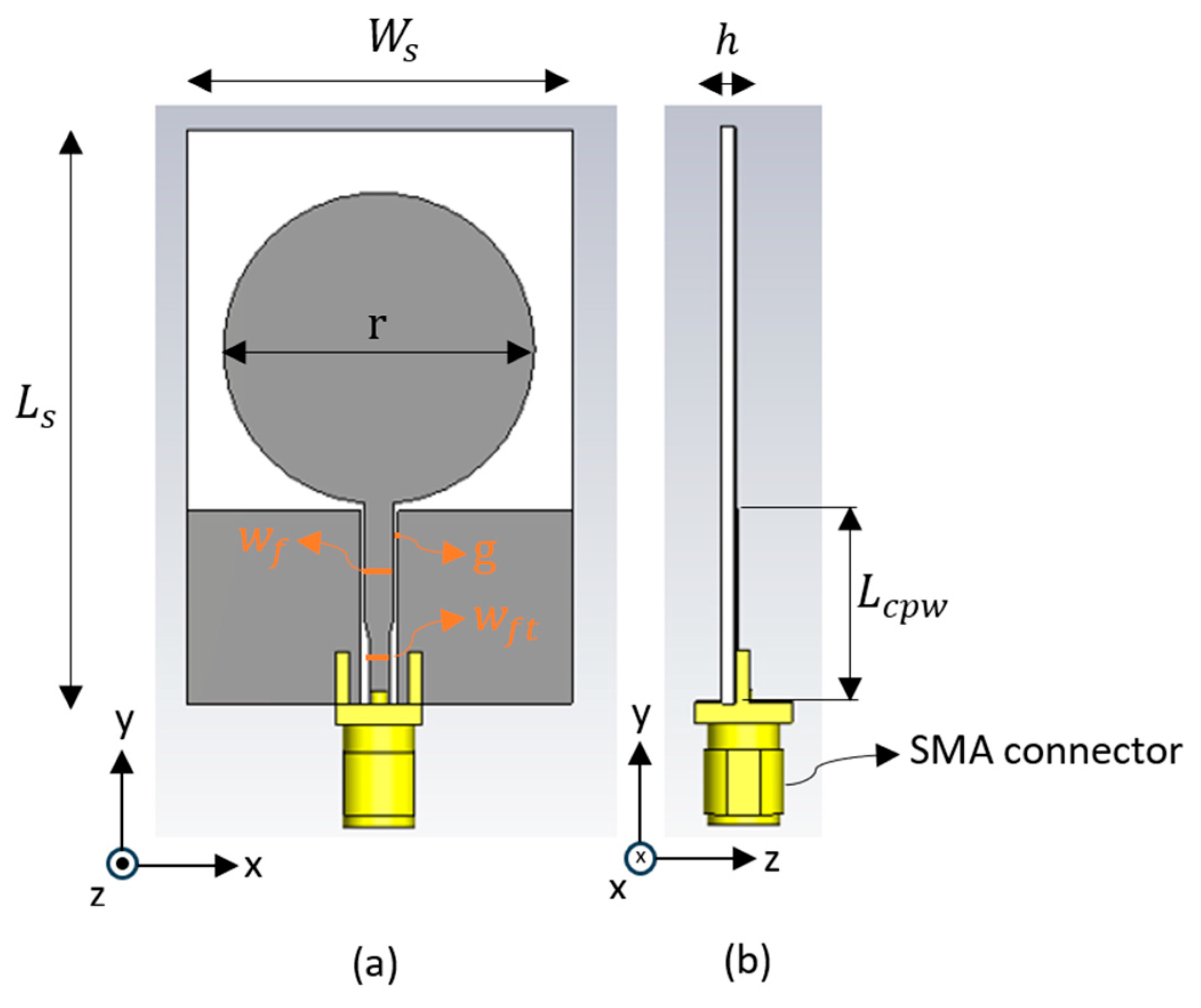
Figure 2.
(a) Aerosol Jet® 5X printing machine, (b) fabricated antenna.
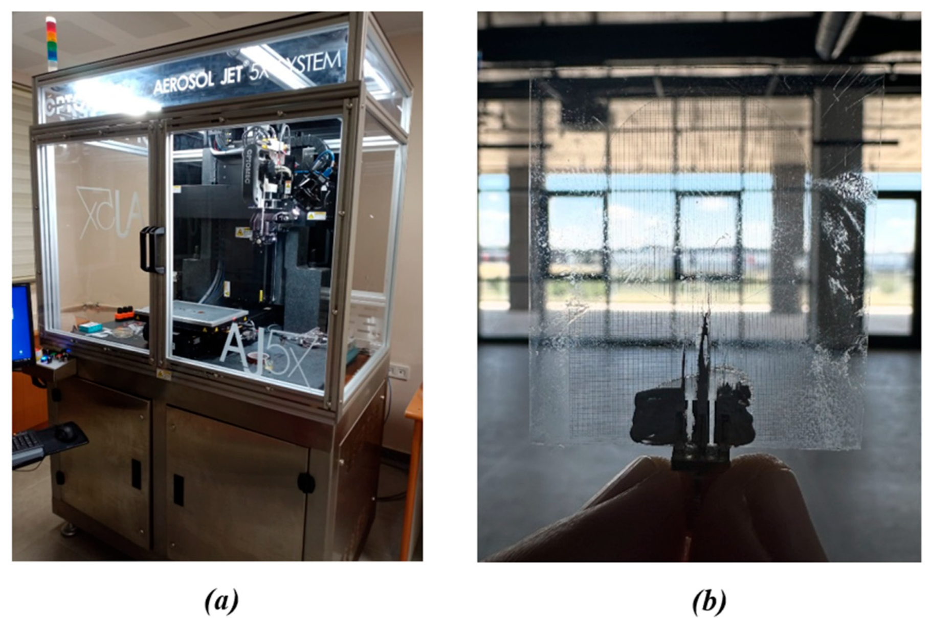
Figure 3.
Measurement setup inside the anechoic chamber.
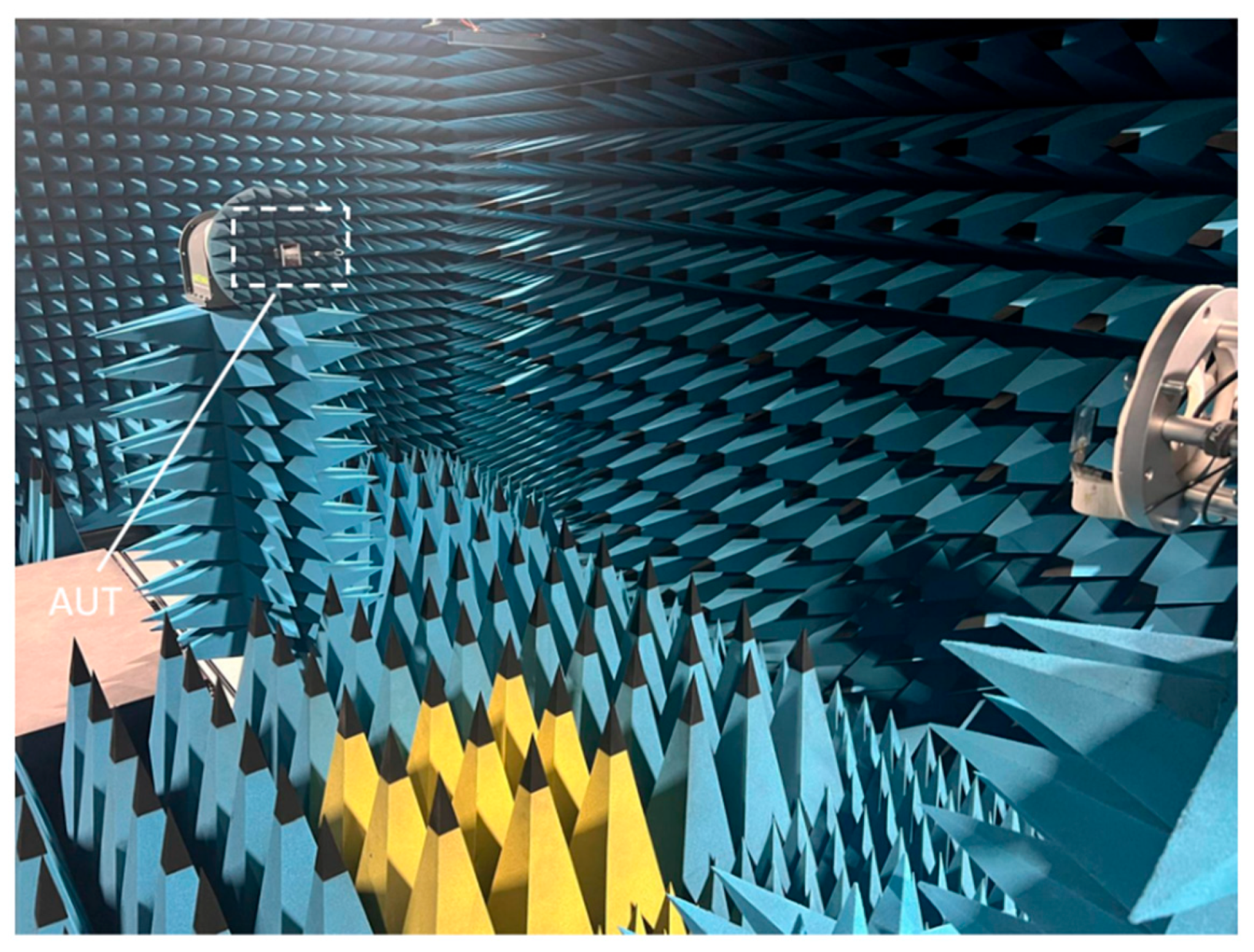
Figure 4.
Measured and simulated results of the antenna reflection coefficient.
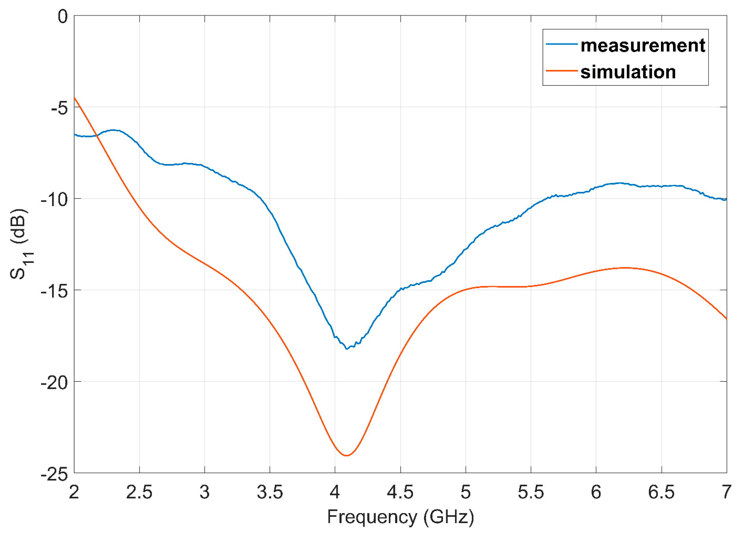
Figure 5.
Measured and simulated co-polarized radiation patterns of the antenna at 4.5 GHz (a) xz-plane, (b) xy-plane.
Figure 5.
Measured and simulated co-polarized radiation patterns of the antenna at 4.5 GHz (a) xz-plane, (b) xy-plane.
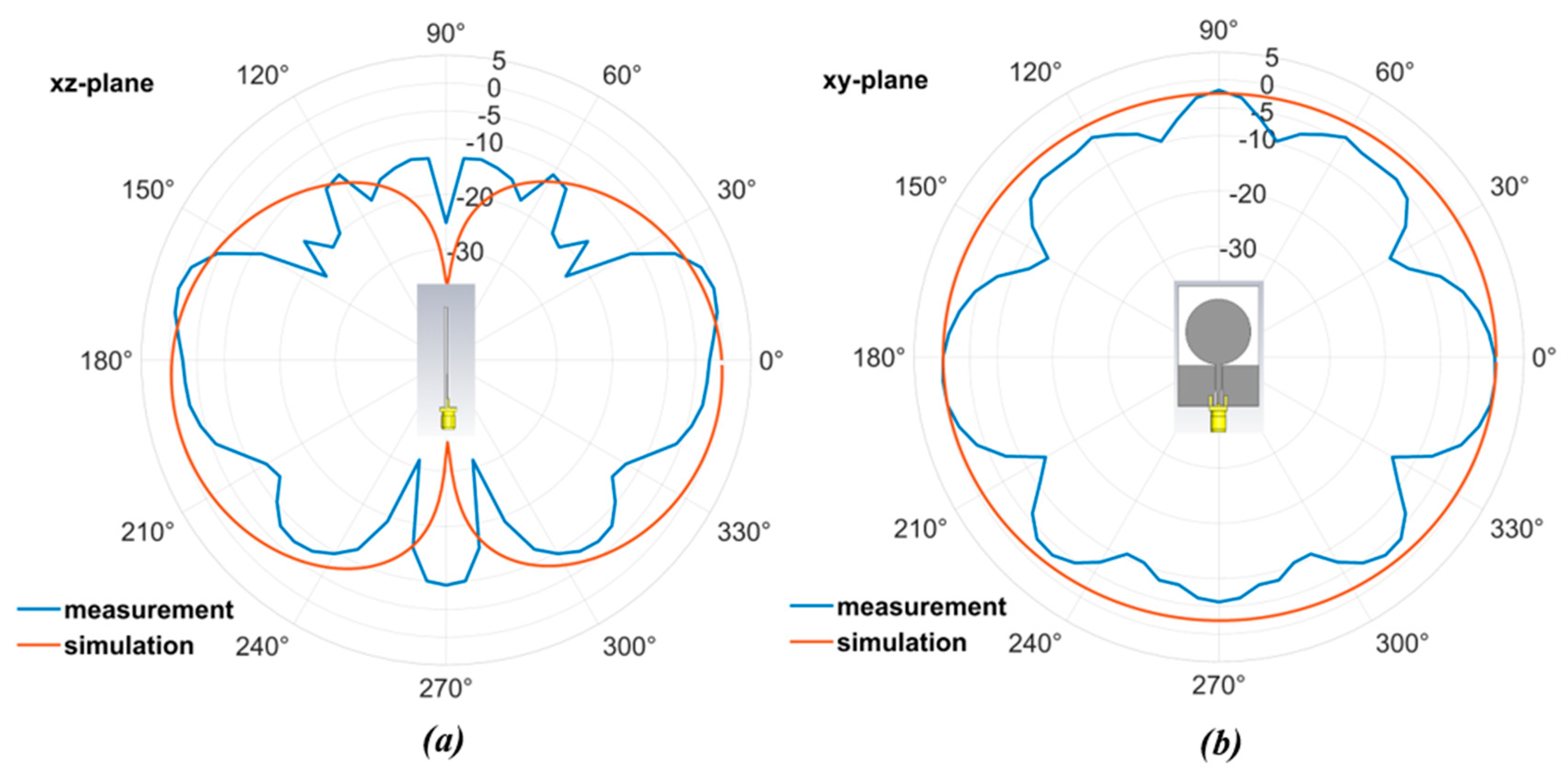
Figure 6.
Measured and simulated co-polarized radiation.
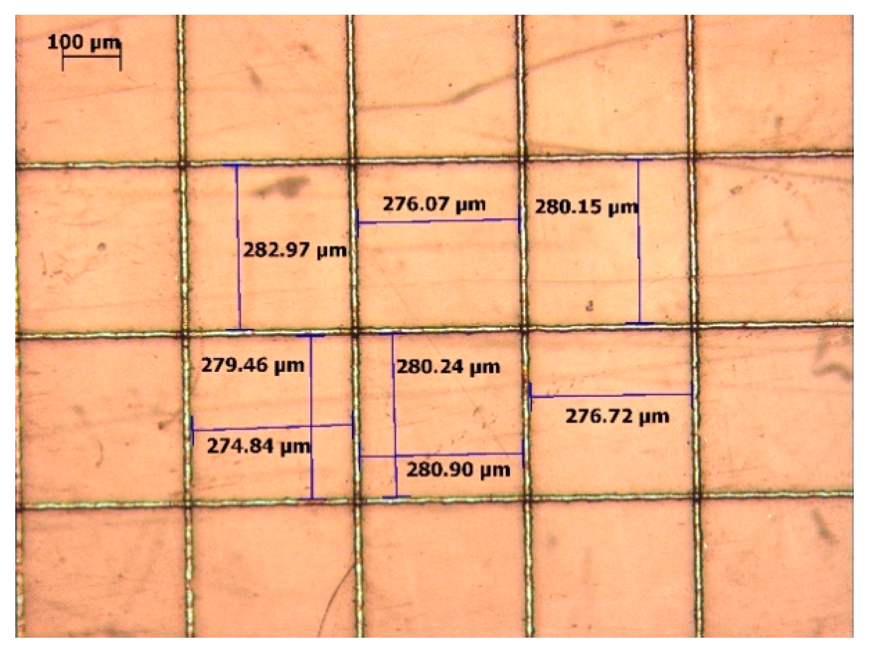
Figure 7.
Measurement setup for the transparent antenna integrated with a photovoltaic solar cell and measured reflection coefficient (S11) comparing the free-space and solar-cell-integrated configurations.
Figure 7.
Measurement setup for the transparent antenna integrated with a photovoltaic solar cell and measured reflection coefficient (S11) comparing the free-space and solar-cell-integrated configurations.
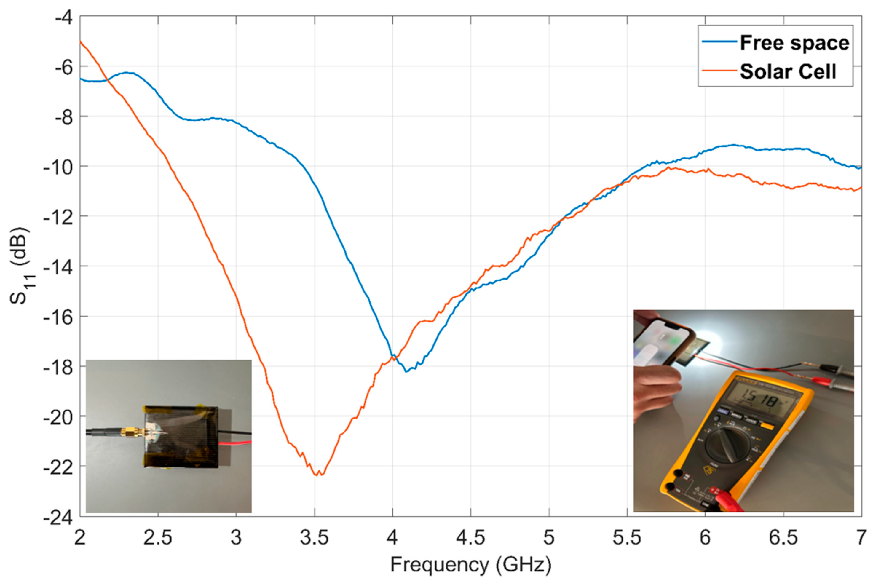
Figure 8.
Measurement setup of the conformal antenna under bending conditions on a cylindrical support and measured reflection coefficient (S11) for free space, cylindrical backing, and conformal bending configurations.
Figure 8.
Measurement setup of the conformal antenna under bending conditions on a cylindrical support and measured reflection coefficient (S11) for free space, cylindrical backing, and conformal bending configurations.
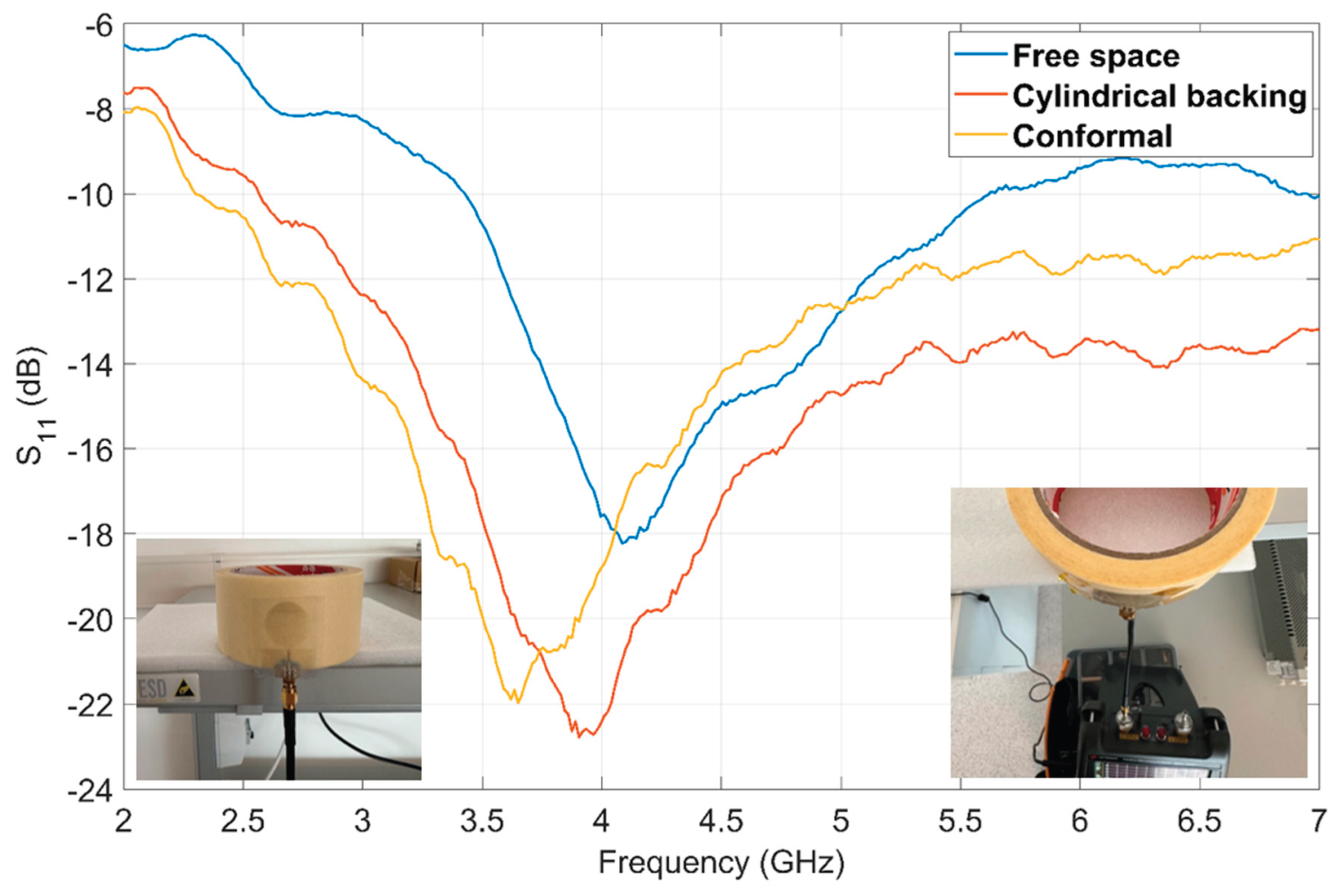

Table 1.
Design parameters of the proposed antenna.
| Parameter | Dimension (mm) |
|---|---|
| 30.00 | |
| 45.00 | |
| 0.05 | |
| 25.00 | |
| 0.20 | |
| 2.20 | |
| 1.60 | |
| 13.50 |
Table 2.
Comparison of the proposed antenna with recently reported antennas.
| Reference | Frequency (GHz) | Conductor Type / Structure | O.T. (%) | Peak Gain (dBi) | Flexibility |
|---|---|---|---|---|---|
| This study | 3–6 | Aerosol Jet® 5X (Metal Mesh) | 85% | -2.5 | High |
| [6] | 2.45 | Ag NWs / Screen Printing | 85% | N/A | Yes |
| [9] | 2.45 | PEDOT: PSS /Aerosol Jet | ~80% | -3.6 | Limited |
| [10] | 3.15–32 | AgHT-8 / Laser Cutting | >75% | -4.8 (Avg) | Yes |
| [13] | 2.99–6.82 | ITO-PET / Manual Cutting | <87% | 1.3 | No |
| [14] | 4.41–4.56 | Wired Metal Mesh | 83% | 3.2 | Yes |
| [20] | 4.4–5 | Ni-Metallic Mesh / Electrodeposition | 91% | 3.8 | Yes |
| [21] | 2.21–6 | AgHT-4 / Manual Cutting | 70% | 0.53 | Yes |
Disclaimer/Publisher’s Note: The statements, opinions and data contained in all publications are solely those of the individual author(s) and contributor(s) and not of MDPI and/or the editor(s). MDPI and/or the editor(s) disclaim responsibility for any injury to people or property resulting from any ideas, methods, instructions or products referred to in the content. |
© 2026 by the authors. Licensee MDPI, Basel, Switzerland. This article is an open access article distributed under the terms and conditions of the Creative Commons Attribution (CC BY) license (http://creativecommons.org/licenses/by/4.0/).
Copyright: This open access article is published under a Creative Commons CC BY 4.0 license, which permit the free download, distribution, and reuse, provided that the author and preprint are cited in any reuse.


