5. Predicting Flame Stability with Ansys
Using hydrogen as fuel, a gas turbine is the appropriate choice from a technical standpoint, since the only difference is a combustor design optimised for hydrogen. This research is a first step toward offshore and marine applications, enabling consideration of hydrogen blending with LNG at 30%, 50%, and 70% to enhance fuel flexibility. The baseline will be an LNG gas turbine, which is widely used in offshore applications.
Whether to use hydrogen-rich fuel depends on whether the combustor employs a diffusion-type flame or a premixing system. Diffusion flames are generated by direct fuel injection into the combustor. Mainly to modify the injector to prevent the risk of producing NOx, which will be higher than LNG. So, we must consider that the pre-mixing system is more reliable for hydrogen fuel usage. Although premixing systems produce lower NOx emissions, this significantly affects combustor research aimed at developing more effective combustors for NOx emission reduction.
Flame stability is a critical criterion in gas turbine combustion design, as it governs both safe operation and emission performance. In ANSYS CFD, predicting flame stability requires coupling detailed turbulence–chemistry interaction models with accurate boundary conditions to capture the complex interplay between fuel–air mixing, ignition, and flame anchoring. Numerical approaches, such as the Flamelet Generated Manifold (FGM), Eddy Dissipation Concept (EDC), or Finite Rate Chemistry models, are applied to resolve the combustion regime. Meanwhile, swirl intensity, equivalence ratio, and combustor geometry significantly influence the flame’s anchoring position and resistance to blow-off or flashback. Stability predictions are validated against experimental benchmarks by comparing key outputs, including temperature fields, velocity profiles, turbulent kinetic energy, and species concentrations. By integrating these models, ANSYS simulations provide a reliable framework for evaluating stability margins of hydrogen, methane, and blended fuels in advanced turbine combustors. [
29]
This study used a simplified CFD model in ANSYS Fluent to verify Aspen HYSYS predictions of pressure loss, temperature, and mass flow in fuel lines for LNG, hydrogen, and blends, focusing on process validation rather than detailed combustor dynamics. A steady RANS simulation with the Realisable k–ε model was applied to internal pipe flow, achieving robust convergence with modest mesh requirements. The fluid was treated as a compressible, temperature-dependent ideal gas, with no-slip, adiabatic boundaries. Results for pressure drop, temperature, and flow were compared to HYSYS for validation.
For the combustor, a more advanced model combining the k–ε turbulence model with a Flamelet-Generated Manifold (FGM) was used to capture flame stabilisation, heat release, temperature non-uniformity, and hydrogen flashback. This approach improves the resolution of recirculation zones and shear layers, capturing the fast chemistry of hydrogen and fuel reactivity without incurring the full finite-rate chemistry costs.
This two-tier modelling approach uses simple k–ε RANS, where one-dimensional physics suffice (fuel lines, ducts), and complex k–ε with FGM for the flame region, which is dominated by turbulent mixing and chemistry. When only outlet temperature, flame speed trends, or overall heat addition are needed, Aspen HYSYS suffices, and CFD is employed only where detailed physical resolution is necessary, balancing efficiency with accuracy.
Ansys Fluent boundary-condition analyses were conducted to determine the turbine combustor inlet temperature, pressure, and flow-field distributions corresponding to the hydrogen-enriched fuel condition. The flame speed, adiabatic flame temperature, and flashback limits obtained from Ansys were used to calibrate the combustion efficiency and temperature limit constraint within Gasturb, ensuring the thermodynamic cycle model operates within physically achievable boundaries. [
30,
31]
5.1. Fueling System to Gas Turbine Combustor
Current industrial research on fuel supply modes is significant for hydrogen gas turbines, including diffusion, premixed, micro-mixed, and DLE (Dry Low Emission) for NOx reduction. In dry low and diffusion combustion, Fuel and air are separately introduced into the combustor, and the flame forms at the interface where they mix. Turbulent diffusion leads to a thick flame front with high local temperatures. Diffusion flames are inherently stable and robust, making them highly resistant to blow-off and flashback, even with highly reactive fuels such as hydrogen; however, their high adiabatic flame temperature leads to substantial thermal NOx formation.
Fuel and air are pre-mixed before being injected into the combustor, generating a homogeneous lean mixture with the equivalence ratio ϕ≈ 0.3–0.6. This significantly lowers flame temperature and reduces NOx formation. Premixed combustors produce shorter, more uniform flames and are widely used in low-emission turbine designs. However, hydrogen’s extremely high laminar flame speed increases the risk of upstream flame propagation (flashback) in premixed systems unless specially designed flame-holding and mixing elements are used. Therefore, although premixing is highly attractive for low-NOx hydrogen combustion, it may require an advanced injector to control real-time Lambda (λ). [
22]
5.2. Ansys Simulation Model
There are three basic types of burners: CAN (or Tubular) Type combustor, CANNULAR (can-annular or turbo-annular) type combustor and ANNULAR combustor. A reduced circumferential sector of the annular combustor was modelled, representing one lab combustor for the full annular combustor. The sector size was selected for numerical convenience and does not imply the number of fuel injectors in the OEM combustor, which typically ranges from approximately 8 to 15. Injector internal geometries were not resolved; therefore, the model represents a generic annular sector with equivalent mass and energy fluxes derived from the system-level Aspen model. A single rectangular combustor cup was used, with boundary conditions obtained by dividing the annular test-rig flow rates. Hydrogen was staged via 12.5 mm jets to achieve injection velocities of (65~140 m/s). In comparison, methane was introduced via two premix jets to promote rapid premixing over a 100 mm premixer. [
30,
31,
32]
This research uses a canonical two-dimensional combustor configuration to examine flame formation and stability of pure hydrogen and hydrogen–natural gas blended fuels under conditions relevant to gas turbines. The canonical geometry represents an intentionally simplified combustion domain that isolates the main physical mechanisms affecting hydrogen flame behaviour, such as mixing-controlled heat release, temperature increase, and flame anchoring. By reducing geometric complexity, the model enables systematic parametric analysis of fuel composition, air–fuel ratio, and inlet conditions while remaining consistent with equilibrium-based combustor models commonly used in system-level tools such as Aspen HYSYS.
The canonical 2D framework offers a computationally efficient yet physically meaningful platform for studying hydrogen flame characteristics without the interference of proprietary or highly specialised combustor designs. Results show clear trends in flame compactness, temperature distribution, and stability margin as the hydrogen fraction rises, providing insights into the hydrogen limits of gas turbine combustion systems. This approach links system-level thermodynamic modelling with flame-scale CFD analysis, establishing a versatile methodology for early-stage evaluation and design screening of hydrogen combustors.
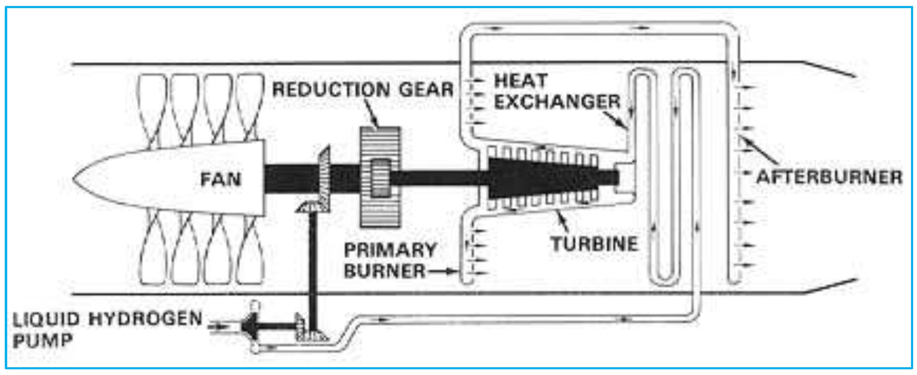
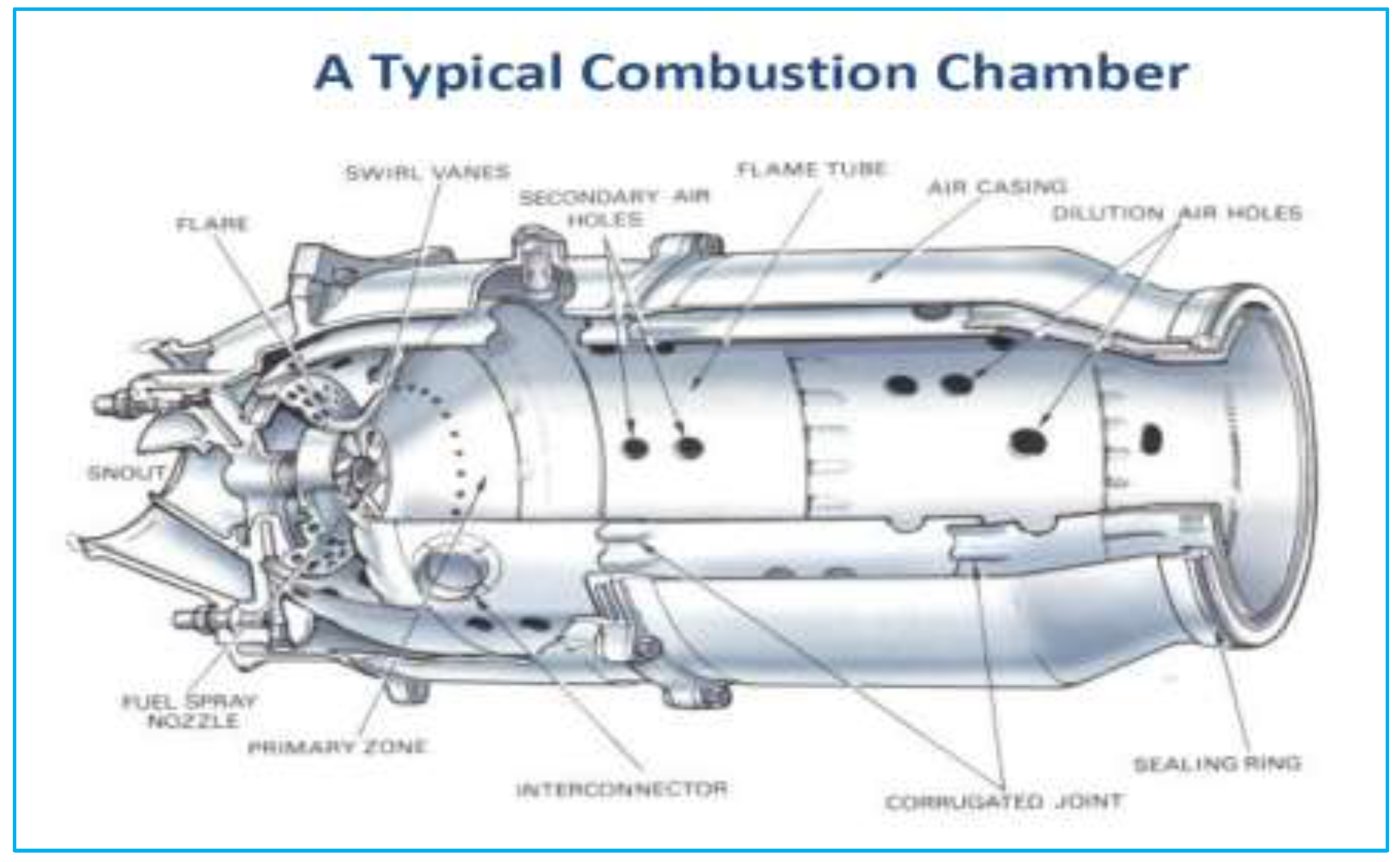
A typical combustion chamber (
Figure 3) has a complex shape to promote smooth flow, with a diffuser to lower the exhaust Mach number. To reduce complexity and meet simulation needs, the lab combustor was modelled as a 2D slice of a large, ~800 mm-long rectangular chamber. This common approach in hydrogen combustor development uses planar slot-type burners to focus on premixing, flame stabilisation, and flashback, avoiding circumferential effects. The 2D method maintains local similarity in Reynolds number, equivalence ratio, and inlet momentum. Mass flow rates are interpreted per unit depth and replicated to account for annular effects. As the main focus is on premixed flame physics rather than annular interaction, this approach is computationally efficient. The k–ε RANS model provides velocity, pressure drops, temperature, and mass-flow details to validate combustion, using two transport equations for turbulent kinetic energy (k) and dissipation rate (ε).
To ensure computational efficiency, a simplified steady RANS simulation using the Reliable k–ε turbulence model is utilised, along with an Aspen HYSYS gas turbine model with global steady-state equations to investigate combustion thermodynamics, predict the combustor exit temperature (T₄), and perform full-cycle integration. This model is popular for its numerical stability, but it has limitations, including poor performance near stagnation points and underpredictions of turbulent kinetic energy under certain conditions. RANS exhibits stable convergence for hydrogen-LNG mixtures while resolving the dominant flow structures required to predict flame anchoring, mixing, and T₄ distribution. [
33]
CFD is used to analyse HYSYS data without requiring a detailed combustor model, particularly when flame structure and mixing behaviour are essential. Therefore, LES (Large Eddy Simulation) and URANS (Unsteady Reynolds-Averaged Navier-Stokes) may be considered for thermodynamic validation or cycle modelling when a combustor model is required to examine flow details related to the complex geometry.
Because gas turbine classification is based on pure hydrogen and hydrogen-methane blend categories, combustor simulations will be conducted across different combustor designs during the research to improve flame stability and prevent flashback, ensuring safety and good engineering practice.
5.3. Role of Plasma-Assisted Energy Input
To further enhance ignition reliability and extend the operability range at very lean conditions, a volumetric plasma energy source is applied in the second-stage region. In the context of this research, the plasma source is treated as an auxiliary ignition and stabilisation mechanism, not as a replacement for chemical heat release. The plasma energy input compensates for short residence times in scaled computational domains, stabilising the hydrogen flame kernel under ultra-lean conditions and enabling consistent comparisons across hydrogen blending fractions. Crucially, the plasma source is implemented as an independent energy term, ensuring that the fundamental combustion chemistry remains governed by species transport and mixing.
This staged premixed hydrogen injection concept is intentionally formulated as research as plasma, rather than a direct representation of any specific industrial combustor. Its purpose is to provide a transparent, scalable, and controllable framework for examining hydrogen interaction effects under gas-turbine-relevant conditions. This premixed-stage combustor is to stabilise the hydrogen flame, primarily by preventing flashback, assessing the impact of staged heat release on temperature and mixing fields, and evaluating the numerical robustness of hydrogen combustion models.
5.4. Pure Hydrogen Combustor Flame Simulation
Hydrogen flame speed is about 250~300 cm/s compared with hydrocarbon gasolines, about 50 cm/s, which means that it is five to six times faster than conventional hydrocarbon fuel. This is important because a fast flame offers several advantages, including complete combustion. Also, hydrogen has the highest specific energy of any gas. During ignition, hydrogen can lead to very high diffusivity and alter flame behaviour. Hydrogen has a high theoretical research octane number (RON) of approximately 130 or higher, but its tendency to auto-ignite complicates its use.
These impacts mean that a gas turbine requires three times the flow rate for the same power output and necessitates adjustments to the fuel accessory system. It has been found that hydrogen is not preferable for pre-ignition, which requires limited operation conditions for lean combustion. Flashback studies of hydrogen-enriched methane-air flames at a constant fuel-air ratio, as hydrogen enrichment can cause flashback. Further development of the proven solution across different burner designs is a promising approach to improving flame stability. [
34]
5.4.1. Non-Premixed Combustion Chamber
A non-premixed (diffusion) combustor introduces fuel and oxidiser separately into the combustion chamber, with mixing and chemical reaction occurring simultaneously within the flame zone rather than upstream of ignition. Flame stabilisation is governed primarily by local jet momentum, shear-layer entrainment, and recirculation or strain-rate balance, making the configuration inherently resistant to flashback and pre-ignition, an essential advantage for high-reactivity fuels such as hydrogen.
In gas-turbine applications, non-premixed combustors typically employ axial or crossflow fuel injection into a high-velocity air stream, where the flame anchors in regions of favourable mixing time and strain rate. Initially set up the test of air velocity of 65.8 m/s and hydrogen velocity of 7.08 m/s to introduce to the non-premixed combustor. Hydrogen combustion was enhanced using the plasma heat-source method, with a constant heat input of 2.5 × 10⁷ W/m3. The hydrogen and air velocity were calculated based on the inlet diameter to get a reasonable air velocity of 100m/s and the hydrogen’s velocity of 42.1 m/s for premixing. The advantage of using plasma to achieve high hydrogen flame speeds is that it allows flashback at high power and enables a stable combustion chain reaction that controls combustion at much lower bulk temperatures than traditional spark ignition. [
31]
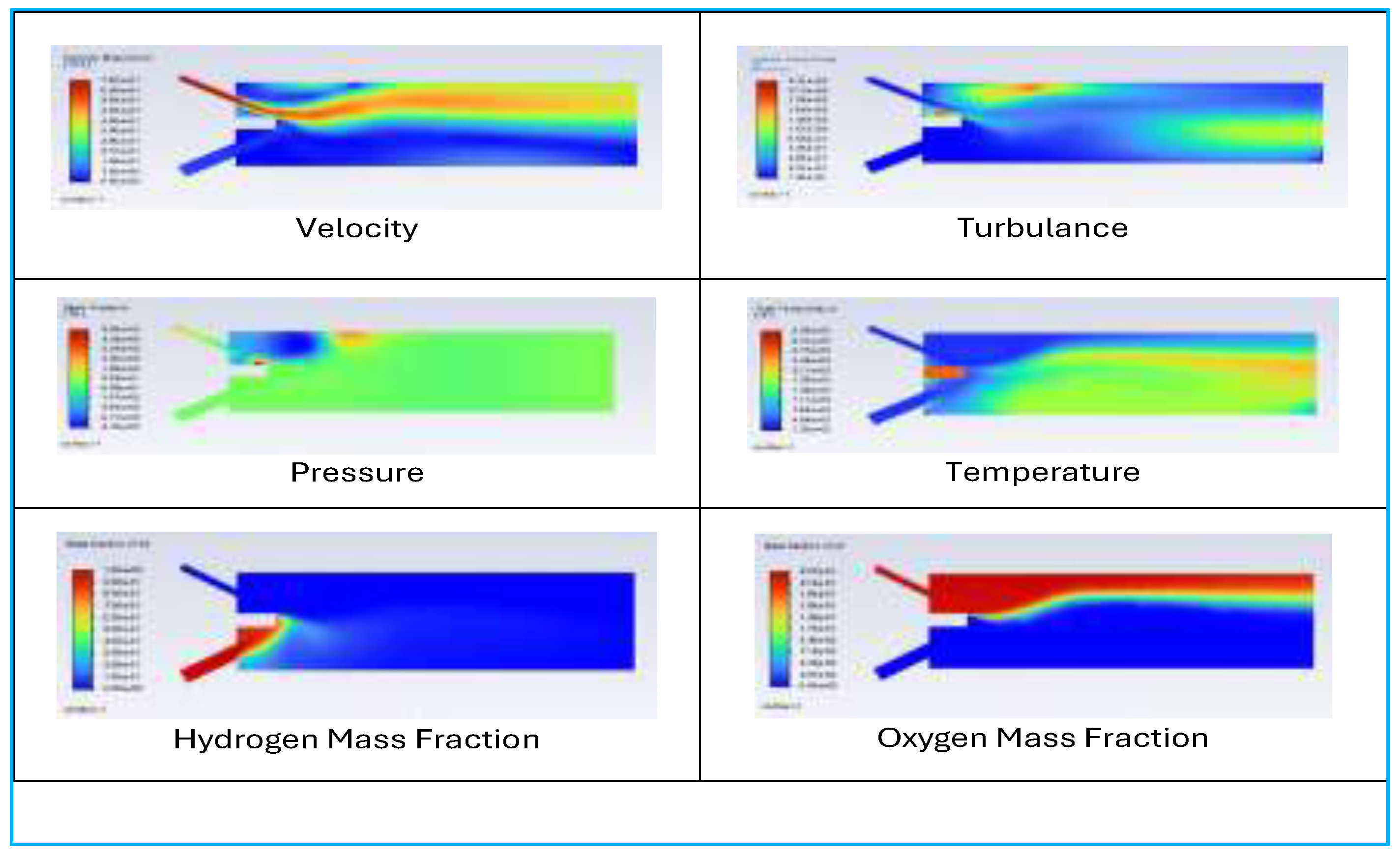
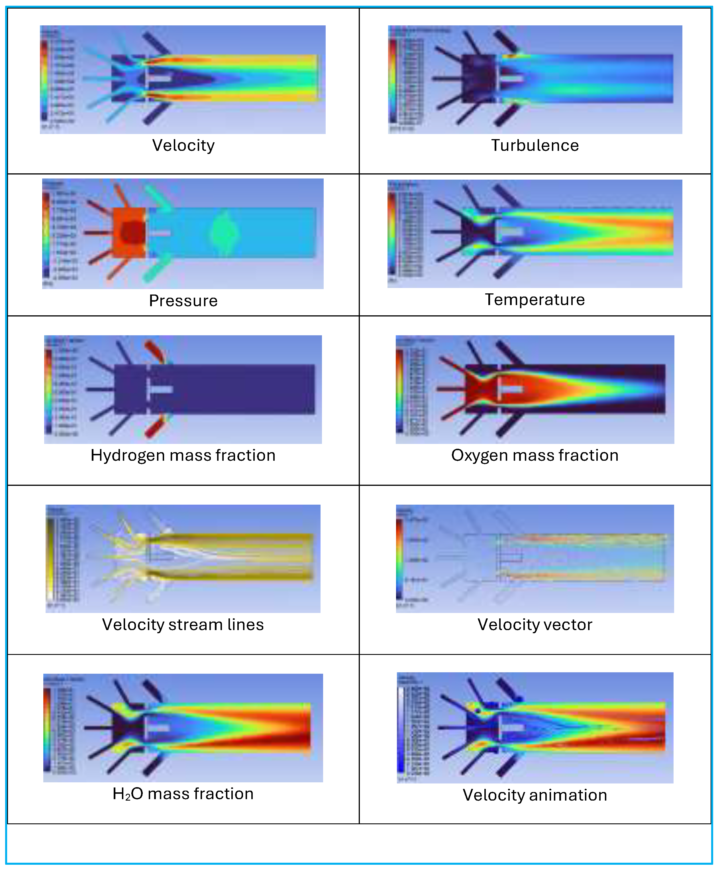
The research presented above concerns a simple flame combustor analysed using CFD, with a progress-variable image representing an instantaneous flame snapshot for visualising combustion velocity. Mass fraction of hydrogen, mass fraction of oxygen, total temperature of the combustor, and analysis for turbulence flow. Here, the research will not provide a deeper discussion for flame analysis, only a superficial focus on the reaction zone, such as the distortion effect of the Eddy phenomenon, the unburnt gas region and the burnt gas region, as well as achievable results from hydrogen feeding from the process flow to the gas turbine, as shown in
Figure 4.
While this architecture is robust and tolerant of fuel variability, its principal limitation is higher thermal NOₓ formation in locally near-stoichiometric reaction zones, necessitating careful control of jet penetration, dilution air staging, or advanced concepts such as micromix injection to maintain acceptable emissions performance.
5.4.2. Pure Hydrogen Premixed Combustion Chamber, Initial Research
The best reference is a 50 MW-class industrial gas turbine with an annular combustor featuring a single annular combustor ring with 8~15 lean-premixed combustor. In this article, the reference is the one with an annular combustion chamber cup to be simulated, which can scale down to 8~15 premixed burners. A simple 2D geometry model with premixed ducts cross-section for air at 25mm Dia inlet tube and hydrogen at 12.5mm Dia inlet tube, and pre-mixed fuel was injected into the combustion chamber.
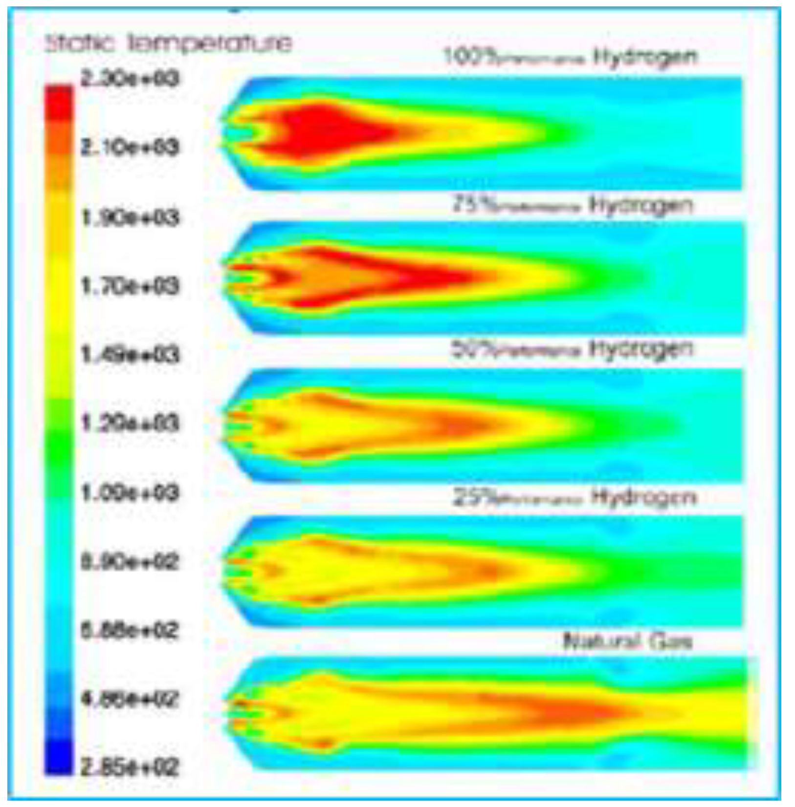
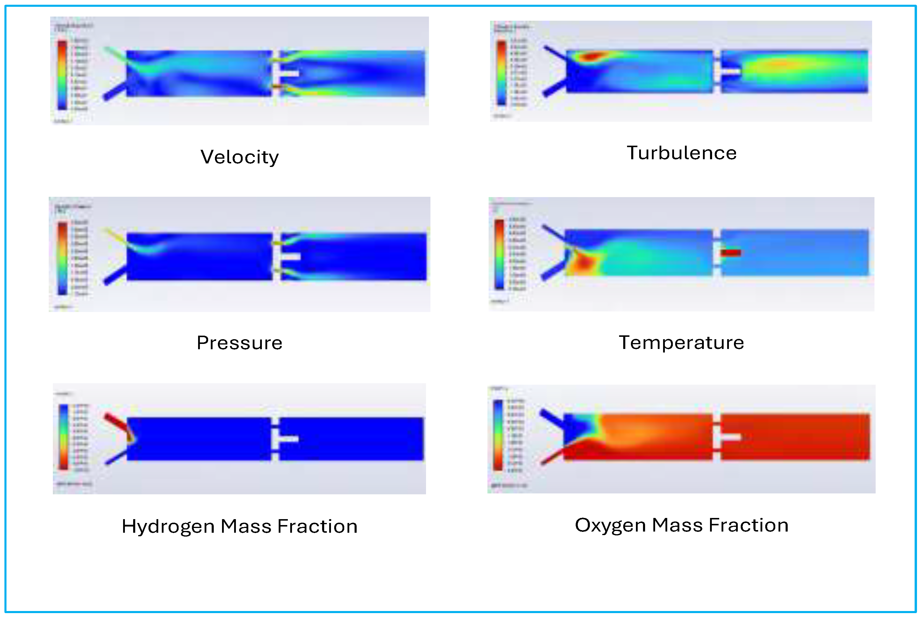
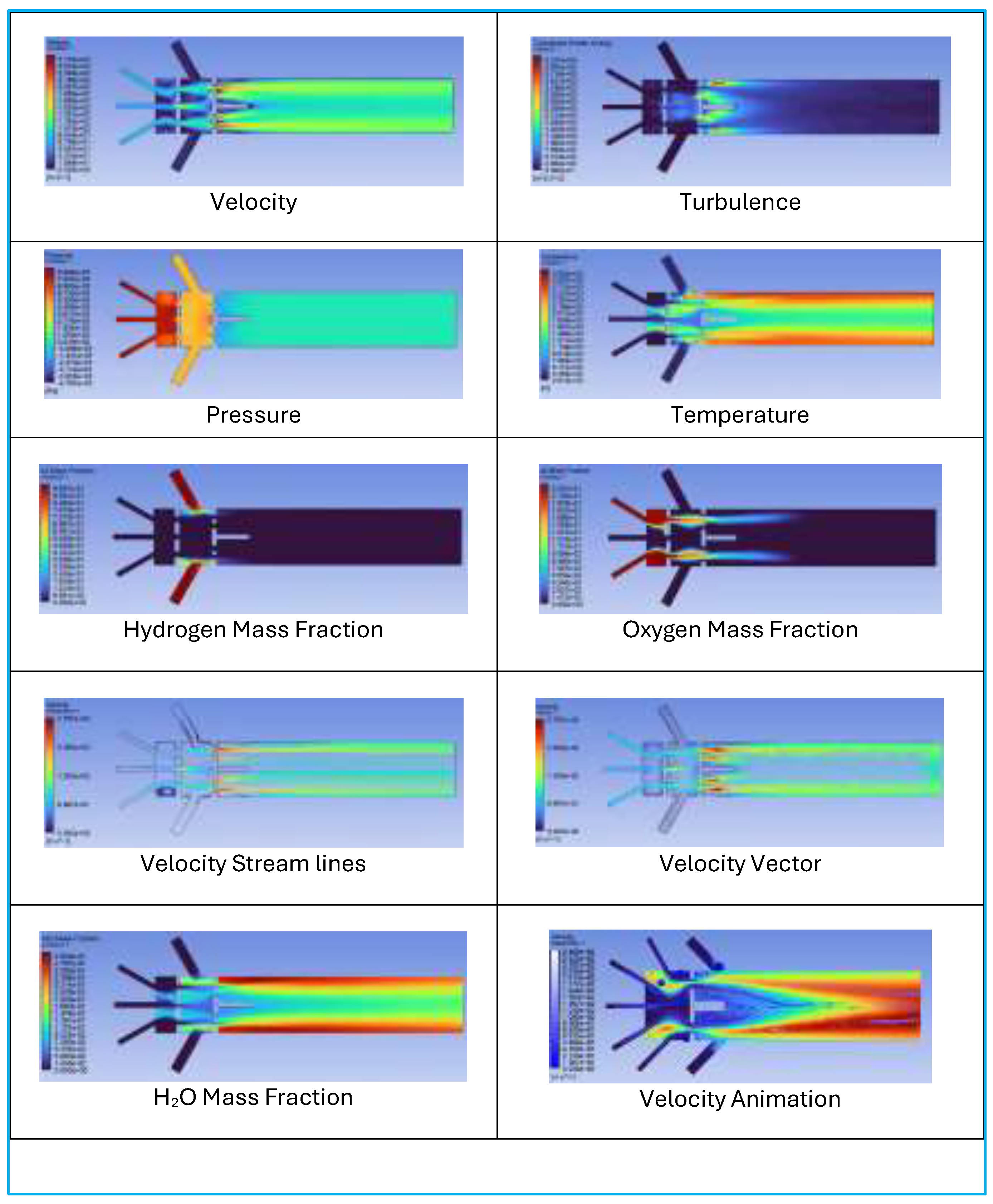
The CFD contour results shown in
Figure 5 provide a comprehensive visualisation of the hydrogen-air premixed combustion process within a nozzle and a combustion chamber. The velocity magnitude contour shows an apparent acceleration of the flow as it passes through the premixing section, with higher speeds developing at the nozzle exit and within the combustion zone, indicating flame propagation and gas expansion. The mass fraction of hydrogen (H₂) exhibits strong injection from the fuel port, mixes with air, and gradually decreases downstream as combustion progresses. In contrast, the oxygen (O₂) mass fraction is initially high in the air stream. Still, it drops significantly upon mixing with hydrogen, confirming the presence of active combustion in the central mixing region. [
35]
The total temperature contour supports the identification of this combustion zone by highlighting a steep temperature rise at the Centre of the chamber, corresponding to the region where hydrogen and oxygen mix and ignite. The highest temperature is concentrated in the core flow, confirming that the flame front is stabilised along the central axis. Finally, the turbulence kinetic energy (TKE) plot shows increased turbulence near the mixing and combustion zones, particularly downstream of the fuel injection and in the nozzle expansion region. This turbulence enhances mixing and supports flame stability. Collectively, these contours demonstrate effective premixing, successful flame stabilisation, and thermochemical conversion of hydrogen within the designed combustor geometry, making this a promising configuration for lean, low-emission hydrogen combustion in gas turbine systems.
The contour report that can be considered a successful RANS (Reynolds-Averaged Navier-Stokes) simulation, as it exhibits key markers of stable hydrogen combustion, which resolved velocity fields, fuel-air mixing, temperature rise, and turbulence behaviour. The results of this CFD contour to use in Aspen HYSYS, and vice versa to ANSYS, in calculations such as inlet and outlet mass flow rates, combustion temperature rise (ΔT across the combustor), fuel consumption (mass or molar basis), and overall energy balance (LHV of hydrogen vs. total heat duty). Additionally, validating species conversion (H₂ and O₂ depletion) and carbon and NOx emissions to bridge the chemical accuracy between Fluent’s detailed reacting flow and HYSYS’s process-level equilibrium model.
5.4.3. Pure Hydrogen Premixed with Second Stage Combustor
Introducing hydrogen into gas-turbine combustion systems presents fundamental challenges due to its high flame speed, low ignition energy, and wide flammability limits. Directly adding hydrogen to the primary combustion zone increases risks of flashback, auto-ignition, and instability. To address this and facilitate hydrogen co-firing research, a staged premixed combustion approach is used, where hydrogen is added downstream of a lean methane-air flame. This decouples heat release from fuel reactivity: methane establishes a stable, lean flame, while hydrogen is introduced separately in a controlled, oxygen-rich environment, enabling its combustion to be studied without destabilising the main flame.
A single laboratory-premixed hydrogen combustor module was defined as a scalable representation of annular gas-turbine combustion by enforcing inlet velocity and mixture strength similarity while allowing multiplicity scaling. The module employs one air inlet (Ø12.5 mm) and one hydrogen inlet (Ø25 mm) feeding a straight rectangular premixer, with inlet velocities set to 65.8 m/s for air and 7.08 m/s for hydrogen to deliver a lean premixed air–fuel molar ratio of 3.0. Annular equivalence is achieved by replicating this validated module to match the target 1/N annular sector mass flows (N = 8–15), enabling a consistent pathway from lab-scale CFD/experiment to sector- and annulus-level performance estimation.
At full-scale, the adopted hydrogen flow rate (1.113 kg/s) implies thermal energy ~133.6 MW and projected to ~37% net efficiency for 50 MW class which is consistent with publicly reported simple-cycle efficiency ranges for industrial and aeroderivative turbines in the 30–60 MW class, supporting the representativeness of the selected GT-aligned boundary conditions, consistent with lean premixed GT hydrogen operation in Aspen Hysys refer to
Table 1.
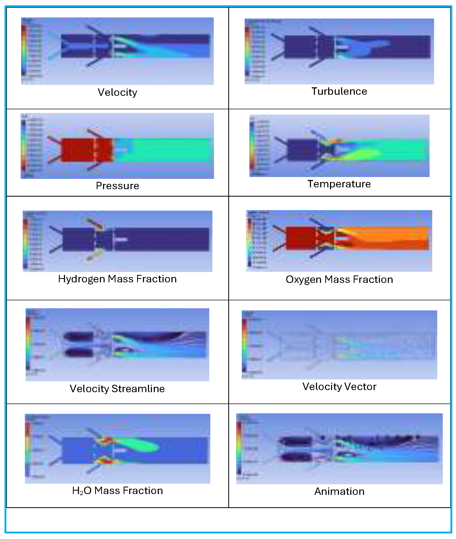
The CFD research on a simple combustor uses a progress-velocity image to visualise combustion parameters, such as velocity, hydrogen, oxygen mass fractions, and temperature, as shown in
Figure 6. The animation reveals detailed flow analysis with streamlines, velocity vectors, and streak lines, showing water vapour bubbles and the Eddy phenomenon, which distinguishes unburnt from burnt gases. This helps improve hydrogen feeding to the gas turbine, though complex geometries pose challenges. The focus on geometry is mainly to match the gas turbine inlet temperature (TIT) with the Aspen test rig, an essential factor.
Pressure contours reveal a localised pressure rise near the fuel injection region, caused by the interaction between high-momentum air and the fuel jets. This pattern, characteristic of lean-premixed combustors, reflects realistic fuel–air coupling rather than instability or backflow. Downstream, the pressure field stabilises. LNG species distribution shows slower radial mixing, with fuel concentrated near the injection region. Adding 30% hydrogen improves downstream mixing, reducing concentration gradients, while 100% hydrogen yields the most uniform axial distribution but requires careful injector sizing to prevent rapid diffusion spreading.
The resulting low fuel-to-air momentum ratio (J ≈ 1.4×10⁻³) indicates that premixing is governed primarily by residence time rather than jet penetration. Accordingly, a straight rectangular premixer with a hydraulic diameter of 40 mm and a length of 0.60–0.80 m was adopted to ensure adequate mixing while minimising the risk of flashback. This laboratory combustor provides a physically consistent basis for CFD analysis and can be replicated to represent multi-cup or annular gas-turbine configurations.
From a modelling standpoint, this approach aligns naturally with species-transport-based CFD frameworks. Second-stage hydrogen reacts according to local oxygen availability and turbulent mixing, rather than being forced by a prescribed global stoichiometric constraint. This makes the configuration particularly well-suited for parametric studies of hydrogen fraction, premixing length, and excess-air ratio.
5.5. Blended Hydrogen with Methane-Air Flame
Methane combustion begins with lean premixed hydrogen blending; in this case, the focus is on a hydrogen fraction 30%, which creates a vitiated mixture of CO₂, H₂O, N₂, and excess oxygen. Hydrogen is injected in a secondary stage, reacting with residual oxygen rather than fresh air. While stoichiometric equations provide conceptual clarity, CFD simulations account for species transport and turbulence-controlled reaction rates, following standard gas-turbine practices and avoiding overinterpretation.
Using pure hydrogen in turbines can reduce emissions, as complete combustion yields near-zero emissions. Its low lean flammability and high mobility enable ultra-lean combustion, but low energy density limits power, which can be addressed through turbocharging and advanced fuel injection. The hybrid Aspen Hysys and Ansys frameworks, validated against industrial data and research, support this discussion.
5.5.1. Blended Hydrogen for Premixed Combustion Chamber
This study investigates a premixed hydrogen–methane combustion in a lab-scale combustor, focusing on mixing, flame stabilisation, and fuel–air interaction under high-temperature, high-pressure conditions relevant to gas turbines. Methane is introduced into the premixing section to create a uniform base with hot compressed air. At the same time, hydrogen is staged directly into the combustion zone to mimic hydrogen-enriched operation and evaluate its effect on flame dynamics.
The premixed setup allows control over the equivalence ratio and hydrogen content without relying heavily on injector hydraulics, thereby isolating the core combustion behaviour associated with hydrogen blending. This approach aligns with standard research methods for examining hydrogen-enriched lean premixed combustion, using specified jet velocities and mass flow rates to simulate desired mixing and reaction conditions. Experiments are carried out on a single rectangular laboratory combustor, functioning as an independent test rig. High-temperature compressed air is supplied via multiple inlets to simulate gas-turbine environments. Methane is injected through jets for rapid mixing, while hydrogen is introduced separately through larger nozzles for staged fuelling. Inlet diameters set boundary conditions for velocities or flow rates, rather than physical dimensions. This configuration allows a systematic study of hydrogen–methane combustion under controlled, CFD-compatible conditions, as depicted in
Figure 7.
CFD results show the combustor flow is dominated by air momentum typical of lean-premixed turbines. Velocity contours reveal a high-speed air core with fuel injected laterally into the air stream. Shear layers facilitate rapid mixing of the hydrogen–methane blend without large upstream recirculation zones, confirming that the injector setup effectively premixes while avoiding prolonged residence time near the fuel injection plane, a vital feature for hydrogen fuels. Compared to pure methane, the 30% hydrogen blend shows stronger fuel–air interaction due to higher jet diffusivity and lower hydrogen density, leading to earlier lateral spreading but maintaining an air-dominated flow. The 100% hydrogen case exhibits the most pronounced jet–crossflow interaction, with fuel penetrating and mixing over a shorter distance and being more sensitive to pressure gradients.
Temperature contours show a smooth axial increase from the premixing section into the main combustor volume. Peak temperatures occur downstream of the injection region, confirming controlled, distributed combustion rather than an anchored diffusion flame. The outlet temperature is uniform, indicating good thermal mixing and a low pattern factor. This aligns with lean-premixed combustion and the simplified geometry’s suitability for turbine inlet temperature analysis. The 30% hydrogen blend results in a smoother temperature rise and more evenly distributed heat release, with a slight downstream shift in the peak temperature, reducing thermal load near the injector. For 100% hydrogen, the temperature field is more compact with a steeper gradient, reflecting faster reactivity, but the outlet temperature remains manageable under lean operation.
Contours of turbulent kinetic energy reveal high turbulence in the shear layers between the fuel jets and the main air stream, enhancing scalar mixing and hydrogen–methane homogenization. Turbulence decays downstream, indicating flow development. The lack of hotspots suggests the injector avoids aggressive jet penetration, thereby reducing pressure loss and flame destabilisation. In the 30% hydrogen case, turbulence is moderately higher than pure methane due to improved shear, aiding mixing without pressure loss. The 100% hydrogen case shows more intense turbulence near injection, reflecting stronger coupling between high-diffusivity jets and the air core. No large flow instabilities occur across cases.
The premixed hydrogen–methane setup in
Table 2 shows stable, well-resolved combustion under gas-turbine conditions. Strong shear and mixing result from inlet velocities and flows, while staged hydrogen addition improves reactivity without instability. In
Figure 7, CFD contours display smooth flow acceleration, a high-temperature reaction zone without hotspots, and consistent turbulence that aids mixing without excessive dissipation. These findings confirm that the boundary conditions and injector design enable effective premixing and controlled heat release, supporting further analysis of hydrogen-enriched premixed combustion in a lab-scale combustor.
The blending scenario with a hydrogen fraction of 30% operates in a transitional regime, combining hydrogen’s mixing and temperature benefits with methane’s flow stability. Comparing 0%, 30%, and 100% hydrogen shows intermediate blends are practical for gradual fuel transition in gas turbines without major combustor redesign. Results indicate a simplified, non-swirl premixed combustor captures key flow, mixing, and thermal traits. The blend improves diffusivity and mixing compared to pure methane, and it operates at controlled temperatures suitable for turbine use.
It features stable, air-driven premixed flow typical of industrial systems, with effective fuel–air mixing without extensive premixing passages, reducing hydrogen flashback risk. Temperatures increase evenly without local overheating near injectors. Turbulence is adequate for mixing, ensuring stable combustion and acceptable pressure loss. The 30% blend exhibits combustion characteristics between methane and hydrogen, with improved mixing, uniform temperature, and stable flow. CFD confirms premixed injection achieves stable, uniform mixing and outlet temperature without high pressure loss, making it a suitable surrogate for hydrogen-enriched gas turbines.
5.5.2. Blended Hydrogen for the Premixed Second Stage Chamber
Introducing hydrogen into gas-turbine combustion presents challenges due to its high flame speed, low ignition energy, and broad flammability range. Adding hydrogen directly to a primary premixed flame increases the risk of flashback, auto-ignition, and instability. This research uses a staged premixed approach, adding hydrogen downstream of an initial lean methane-air flame to separate heat release from fuel reactivity. Methane stabilises the lean flame due to its lower flame speed and higher ignition temperature, while hydrogen is added separately for controlled, oxygen-rich combustion without destabilising the primary flame. This method serves as a research platform, ensuring practical, transferable findings. Initially, methane burns lean with excess air, producing a high-temperature, vitiated flow containing residual oxygen, nitrogen, water vapour, and CO₂, with an equivalence ratio below stoichiometric levels.
From a research perspective, this stage serves three critical functions:
✓ Thermal conditioning – raising the gas temperature to levels favourable for hydrogen ignition without external heating.
✓ Oxygen buffering – providing a controlled reservoir of oxidiser for secondary hydrogen combustion.
✓ Stability anchoring – isolating the stabilisation of the primary flame from the highly reactive hydrogen fuel.
In the second stage, hydrogen is introduced as a premixed stream into the vitiated products of the first stage rather than into fresh air. This design choice is central to the research hypothesis. By premixing hydrogen with a fraction of the hot vitiated gases before combustion, several advantageous conditions are created:
✓ Dilution effects from CO₂, H₂O, and N₂ reduce local flame speed and suppress flashback propensity.
✓ Elevated background temperature lowers ignition delay, enabling reliable hydrogen combustion at ultra-lean conditions.
✓ Residual oxygen control ensures that hydrogen reacts primarily with excess oxygen from the first stage rather than competing directly with methane.
This separation allows hydrogen effects to be examined independently of the primary flame anchoring mechanisms. In the second stage, hydrogen is introduced as a pre-mixed stream into the vitiated products of the first stage rather than into fresh air. This design choice is central to the research methodology.
Table 3.
Second stage Lab combustor inlet design table.
Table 3.
Second stage Lab combustor inlet design table.
| Stream |
Injection zone |
No. of inlets |
Diameter (mm) |
Temperature (°C) |
Pressure (bar) |
Mass flow (kg/s) |
Velocity (m/s) |
Notes |
| Air |
Premixed zone |
3 |
12.5 |
15 |
21.72 |
80.21 |
68.5 |
The high-enthalpy air inlet serves as the numerical boundary, |
| Methane (CH₄) |
Premixed zone |
2 |
12.5 |
75 |
39 |
3.404 |
58.8 |
Velocity prescribed for shear-driven premixing; mass flow derived |
| Hydrogen (H₂) |
Second stage zone |
2 |
25 |
75 |
39 |
0.7739 |
7.08 |
Staged hydrogen injection for flame-zone enrichment |
Premixing hydrogen with hot vitiated gases before combustion creates advantages: dilution from CO₂, H₂O, and N₂ reduces flame speed and flashback risk. Elevated temperature lowers ignition delay, enabling reliable ultra-lean hydrogen combustion. Control of residual oxygen ensures hydrogen reacts mainly with excess oxygen, not methane. The second stage’s premixing length balances mixing with the need to prevent upstream auto-ignition. Hydrogen mainly reacts with residual oxygen, producing more water and heat downstream, which reduces peak flame temperatures and helps study hydrogen’s effect on flame structure and heat distribution without destabilising the methane flame. Injecting hydrogen into an oxygen-rich, vitiated environment minimises flashback, moderates temperature, and isolates hydrogen reactivity from flame stabilisation. This staged setup facilitates research on hydrogen co-firing under gas turbine conditions without reliance on a proprietary combustor, focusing on hydrogen ignition, flame stability sensitivity, staged heat-release effects, and model robustness.
The hydrogen-enriched flame at 30% H₂ (molar basis) shows clear differences in combustion characteristics compared to pure methane operation. Velocity and turbulence kinetic energy contours highlight stronger shear layers downstream of the second-stage injection and micro-mix transfer ports, leading to faster fuel–air homogenisation. This improved turbulent mixing shortens the ignition delay and shifts the main heat-release zone forward, as evidenced by the earlier temperature rise and a more compact flame envelope. Despite the higher reactivity due to hydrogen, the temperature field remains spread out rather than concentrated, confirming that combustion remains mixing-controlled under lean conditions.
The plasma-assisted ignition zone provides steady flame anchoring without causing upstream flashback or premature ignition in the premixing passages. Species contours further show the stabilising effect of adding a moderate amount of hydrogen. Hydrogen mass fraction declines quickly downstream of injection, indicating rapid consumption and efficient entrainment into the methane–air mixture, while oxygen depletion continues smoothly along the flame core. The pressure field remains relatively uniform across the premixed stages and the combustor inlet, suggesting that the 30% hydrogen blend does not cause a significant pressure loss.
The results also show that hydrogen velocity can be further increased, as indicated by the CFD results, which display stable combustion. While stoichiometric reaction equations are provided for conceptual clarity and energy-balance validation, the CFD simulations solve species transport equations with turbulence-controlled reaction rates, as shown in
Figure 8. This separation between chemical representation and numerical implementation follows established gas-turbine combustion modelling practices and avoids over-interpretation of global reaction equations.
Compared to the LNG baseline, the 30% hydrogen case shows earlier flame ignition, increased turbulence mixing, and shorter lift-off distance. The methane-only flame has a longer reaction zone and a delayed peak temperature due to slower kinetics. Hydrogen enhances radical chemistry and jet–shear interactions, improving flame anchoring and reducing flow sensitivity, while maintaining similar pressure profiles. Compared to 100% hydrogen, the 30% blend is more distributed and thermally moderated. Pure hydrogen has compact, high-intensity zones with flashback risk, but blending with methane moderates flame speed and heat release.
This balance offers stable ignition and controllable propagation, serving as an intermediate between LNG and full hydrogen flames. As hydrogen increases from 0% to 30%, flame length shortens, ignition shifts upstream, and turbulence–chemistry interactions grow stronger, while pressure and flow remain stable. Peak temperature becomes more evenly spread. Approaching 100% hydrogen suggests further flame shortening, higher reactivity, and more stabilisation needs. Thus, 30% hydrogen offers a good compromise of stability and enhanced ignition and mixing.
Overall, these features imply that moderate hydrogen enrichment improves flame stability and ignition robustness while maintaining the essential lean-premixed combustion regime needed for low-emission gas-turbine operation. Methane combustion in the primary stage is modelled as lean premixed oxidation, producing a vitiated mixture containing CO₂, H₂O, N₂, and excess oxygen. Hydrogen is then injected in a secondary premixing stage and reacts with the remaining oxygen rather than with fresh air.
5.6. Hybrid Combustor Design Approach for Micro Mixer
The above innovation study explores hydrogen–LNG combustion strategies using four simplified hybrid combustor models, each represented as a rectangular combustor, capturing key physical mechanisms such as fuel staging, distributed injection, residence time, and near-wall flow behaviour. Idea that integrates micromix-inspired distributed pilot injection with a lean premixed main flame to prevent flashback and enable low-NOx lean operation. Also, add the feature of axial fuel staging under consistent turbine inlet temperature control, separating heat-release effects from the overall thermal load, utilising lean direct injection through multiple fuel jets to eliminate upstream premixing lengths and reduce flashback routes, which prioritises flashback prevention by focusing on near-wall velocity and temperature conditions rather than detailed flame structure and combustor design, refer to
Table 4.
This study introduces a TIT-controlled hybrid staged combustor that integrates a distributed micromix-like stabilising stage with a lean premixed main burn. The design aims to address hydrogen’s primary challenges, boundary-layer flashback tendency and high thermal NOx, while maintaining operability through fuel staging from 0 to 100% H₂ blending. System-level combustion thermodynamics and TIT limitations are derived using Aspen HYSYS, complemented by simplified CFD to assess peak temperature distribution, mixture uniformity, pressure loss, and a near-wall flashback margin indicator.
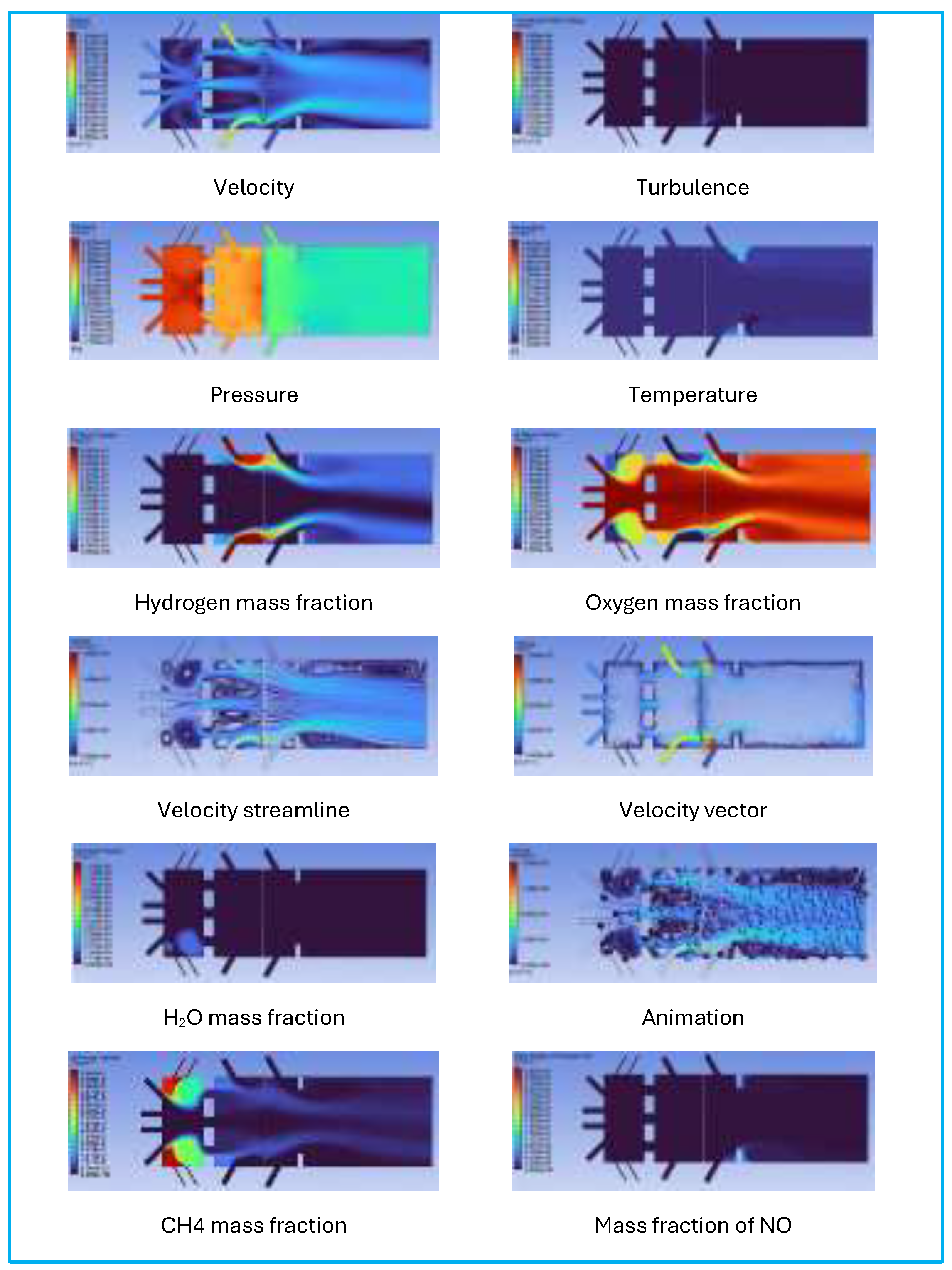
Examining the flow results, as shown in
Figure 9, the mixing and staging behaviour, and the velocity and turbulence fields, the two-stage architecture effectively establishes a controlled flow hierarchy between the premixing, transfer, and combustion zones. High-momentum jets at the micro-mix injectors create strong shear layers that enhance rapid entrainment and mixing. At the same time, the upstream premixed stage provides a stable, well-conditioned inflow into the second stage. The transfer ports efficiently redistribute momentum, smoothing the velocity profile and preventing excessive jet impingement downstream. Turbulence kinetic energy remains concentrated near the injection and shear regions and diminishes along the combustor length, indicating efficient mixing without large-scale flow separation or recirculation that could cause pressure losses or instability. The pressure contours show a steady pressure drop across the stages, consistent with the design intent and with no evidence of adverse backflow.
Observing the thermal field, species distribution, and emissions trend, the temperature and species mass-fraction contours reveal that combustion is spatially distributed rather than concentrated in a single flame front, aligning with micro-mixing. Hydrogen is quickly consumed near the injector exits, forming multiple localised reaction zones that merge downstream into a uniform high-temperature core, while avoiding extended hot spots along the walls. The resulting temperature field remains relatively uniform throughout the main combustion chamber, resulting in a low pattern factor at the outlet. Oxygen depletion and product species distributions indicate efficient overall combustion with limited residence time at peak temperatures. Correspondingly, the predicted NO mass fraction stays low and localised, reflecting suppression of thermal NOx formation due to distributed heat release and lean operation. Overall, the results verify that the hybrid two-stage micro-mix concept attains stable combustion, effective mixing, and reduced emissions propensity under gas-turbine-relevant flow conditions.
This method involves a reference article and the Aspen HYSYS model, which provides system-level combustion thermodynamics and target T₄. At the same time, steady RANS CFD evaluates mixing quality, maximum temperature footprint, pressure loss, and flashback risk. The hybrid micromixer-type lab combustor uses staged premixed methane for stabilisation and high-momentum distributed hydrogen micro-jets for flashback-safe heat release, with plasma assistance for ultra-lean ignition, enabling a controlled investigation of hydrogen-dominant combustion at gas turbine-relevant velocities. This allows consistent comparison of hydrogen combustion strategies across different blend ratios, aligning with industry standards and academic validation.
5.7. Validation with OEM Burner for Ansys CFD Simulation
5.7.1. Flame Study for OEM’s Principle
In the flame study, the Aspen HYSYS blended-fuel combustor model was validated against these principles using non-constraint cases at 30%, 50%, and 70% hydrogen. In this validation, the focus is primarily on the 30% hydrogen fraction case, which is most practical for comparison with the current OEM design development. Although Aspen does not resolve flame-scale physics, such as micromix jets or premixer recirculation, the agreement in global performance metrics demonstrates that the model is suitable for comparing hydrogen co-firing behaviour.
In this case, the fuel-gas combustor was modelled using a deliberately simplified CFD approach in ANSYS Fluent to work with Aspen Hysys. The objective was not to resolve detailed combustor swirl or flame dynamics, but instead to verify the one-dimensional Aspen HYSYS predictions of pressure loss, temperature changes, and mass-flow distributions in the fuel lines for LNG, hydrogen, and blended fuels. Accordingly, a steady Reynolds-Averaged Navier–Stokes (RANS) formulation with the Realisable k–ε turbulence model and scalable wall functions is to be adopted.
5.7.2. Combustion Principle of OEM’s Gas Turbine
In combustion principle, the Kawasaki L30A adopts a fundamentally different hydrogen strategy compared with Siemens DLE (Dry Low Emission) and GE DLN (Dry Low Nox) systems, relying on micromix combustion rather than large-scale lean premixing. In the micromix concept, hydrogen is injected through many small ports, producing distributed micro-jets and short micro-flames with minimal upstream premixing. This design philosophy is explicitly aimed at managing hydrogen’s high flame speed and flashback propensity while maintaining low NOₓ through locally lean, spatially distributed reaction zones.
In this thesis, the Aspen HYSYS blended-fuel combustor is not intended to replicate micromix burner geometry, but rather to reflect the system-level consequences of this philosophy: stable heat release, controlled turbine inlet temperature (T₄), and acceptable efficiency across hydrogen blending. The 30–70% H₂ range selected, therefore, lies well within the operational regime typically discussed for Kawasaki micromix systems and is appropriate for validation against Aspen’s global combustion model. [
10,
35,
36]
To ensure consistency with the Siemens SGT-800 and GE LM6000 validations, the Kawasaki L30A comparison is conducted at constant shaft power, rather than continuous fuel flow or burner-specific parameters. In the Aspen HYSYS model, the blended cases (30%, 50%, and 70% H₂) are evaluated by holding T₄ (TIT) constant while allowing total fuel molar flow and air flow to adjust to the decreasing blended LHV. This mirrors the operational intent of micromix combustion, where power output is maintained by distributing fuel among many micro-jets rather than increasing local equivalence ratio.
The resulting Aspen trends show increased total fuel flow, reduced required airflow, and stable efficiency, consistent with Kawasaki’s micromix objective of avoiding local hot spots while maintaining global turbine performance. When tabulated alongside Siemens and GE, the Kawasaki case can therefore be compared directly using the same metrics: power, fuel flow, air flow, AFR/λ, and efficiency.
From a hydrogen operability standpoint, micromix combustion addresses flashback and NOₓ challenges through geometric and spatial flame control, rather than relying solely on large excess air margins. Although Aspen HYSYS does not resolve micro-scale flames, the model implicitly accounts for micromix constraints by maintaining stable T₄, avoiding abrupt efficiency losses, and preserving lean global conditions across all blended cases. The absence of sharp efficiency penalties or non-physical fuel-air requirements in the 30–70% H₂ range supports the interpretation that the Aspen model remains compatible with Kawasaki’s micromix combustion envelope at the system level. [
37]
Table 4.
Analysis of OEM’s different design concepts.
Table 4.
Analysis of OEM’s different design concepts.
| Description |
Siemens Energy – SGT-800 (DLE) |
GE Vernova – LM6000 (DLN) |
Kawasaki Heavy Industries – L30A (Micromix) |
| Turbine class |
~50 MW industrial |
~50 MW-class aeroderivative |
~30–40 MW industrial |
| Combustion method |
Lean / partially premixed DLE |
Lean premixed, staged DLN |
Distributed micromix (micro-jets) |
| Hydrogen range assessed |
30–70% (100% separate) |
30–70% (within DLN envelope) |
30–70% (within micromix regime) |
| Load control basis |
Constant power, constant TIT |
Constant power,
constant TIT |
Constant power,
constant TIT |
| Lean margin (λ) |
constant |
constant |
lean |
| NOₓ control |
Lean premix, low peak T |
Lean premix with staging |
Short flames, spatial dilution |
| Flashback |
Lean margin |
Lean margin, staging |
Geometric micromix control |
Table 4 demonstrates that, despite fundamentally different burner architectures, the Aspen HYSYS blended-fuel model reproduces consistent system-level behaviour across Siemens DLE, GE DLN, and Kawasaki micromix combustion concepts when evaluated on an identical constant-power, constant TIT basis.
In the combined OEM validation table, this allows the Kawasaki L30A to be assessed on an equal thermodynamic footing with Siemens DLE and GE DLN 2.6+, despite the fundamentally different burner concepts. Consequently, the Aspen HYSYS blended-fuel model is validated as a technology-agnostic, system-level tool, suitable for comparative assessment of hydrogen co-firing across all three OEM combustion philosophies. Across Siemens, GE, and Kawasaki gas turbines, hydrogen co-firing is governed by different burner designs, such as lean/partially premixed DLE, staged lean premixed DLN, and micromix combustion.
All three converge on the same system-level operating principles at constant turbine inlet temperature (TIT), load-controlled operation, lean equivalence ratios, and avoidance of local stoichiometric hot spots. For all three OEM designs, Aspen reproduces the expected thermodynamic trends: decreasing blended LHV with increasing hydrogen fraction, compensatory increases in total fuel flow, reduced air demand, and stable shaft efficiency at constant power.
5.7.3. OEM-Interpolate Check
An OEM-interpolate check was performed using non-proprietary design metrics (bulk premixer velocities, staged residence times, Mach number, and equivalent flow area). The proposed staged premixed configuration maintains Stage-1 air bulk velocity within 30–80 m/s, Stage-2 hydrogen jet velocity within 80–200 m/s, transfer velocity within 50–120 m/s, and Mach number below 0.3, which are representative of DLN-class combustor flow regimes. The larger equivalent inlet diameters are interpreted as aggregated swirler/slot passage area rather than single physical tubes, enabling a simplified rectangular test combustor to remain dynamically consistent with annular combustor flow scaling.
Gas turbine lab combustor
model Parameter
|
Interpolated
“DLN-class” band
|
proposed design |
| Stage-1 air bulk velocity |
30–80 m/s |
60 m/s |
| Stage-1 CH₄ jet velocity |
30–100 m/s |
~50 m/s |
| Transfer to stage 2 velocity. |
|
|
| Stage-2 H₂ jet velocity |
80–200 m/s |
150 m/s |
| Transfer to combustor velocity |
50–120 m/s |
80 m/s |
| Mach number |
<0.3 preferred |
0.09–0.13 |
Premix residence time
(0.25–0.45 m / 60–150 m/s) |
~2–10 ms |
~3–8 ms |
This Ansys model exhibits robust convergence behaviour with modest mesh requirements, making it appropriate for parametric studies across multiple fuel compositions and operating points. The working fluid was treated as a compressible, temperature-dependent ideal gas, and no-slip adiabatic wall boundaries were assumed unless otherwise stated. Simulation results for pressure drop, outlet temperature, and mass flow rate are directly compared with HYSYS predictions to provide a simple validation of the process-level fuel-supply model.
This unified validation framework enables consistent comparison of Siemens SGT-800, GE LM6000, and Kawasaki L30A concepts within a single modelling environment, while reserving detailed CFD for burner-specific investigations beyond the scope of this thesis. [
10,
36,
37]
5.8. Studies on NOx Emission in Hydrogen Gas Turbine
NOx behaviour in hydrogen-fired gas turbines is governed primarily by thermal NOx mechanisms rather than fuel-bound nitrogen, since hydrogen contains no intrinsic nitrogen species. In the present study, hydrogen combustion exhibits a substantially lower NOx tendency compared to LNG when operated under ultra-lean premixed conditions, despite hydrogen’s inherently higher laminar flame speed. Also, the air intake is to be treated as using a splitter for Nitrogen.
Model results show that the hydrogen case operates at λ values an order of magnitude higher than those of the LNG baseline, leading to substantial attenuation of temperature-dependent NOx formation rates. Consequently, when hydrogen combustion is controlled adequately through lean or staged premixing strategies, NOx emissions can be reduced by more than an order of magnitude relative to conventional natural-gas operation, even at comparable turbine power output. [
38]
Table 5.
Gas Combustor Simulation Conditions and Relative NOx Index.
Table 5.
Gas Combustor Simulation Conditions and Relative NOx Index.
| H₂ fraction (%) |
AFRₛₜ (mass) |
λ |
T₃ Air (°C) |
T₄ Hot Gas (°C) |
p₃ (bar) |
p₄ (bar) |
Fuel flow (kg/s) |
Air flow (kg/s) |
Relative NOx index |
| 0 |
11.21 |
3.38 |
547.5 |
1204.8 |
21.82 |
19.82 |
3.11 |
117.87 |
1.000 |
| 30 |
10.2 |
5.8 |
548 |
1050 |
21.82 |
19.82 |
2.75 |
145 |
0.62 |
| 50 |
9.2 |
9.6 |
549 |
920 |
21.82 |
19.82 |
2.30 |
170 |
0.32 |
| 70 |
8.2 |
16.5 |
549 |
780 |
21.82 |
19.82 |
1.75 |
200 |
0.13 |
| 100 |
7.24 |
28.44 |
550.0 |
616.7 |
21.82 |
19.82 |
1.08 |
222.27 |
0.026 |
This reduction is driven by the combined effects of significantly lower combustor exit temperature and markedly higher excess air ratio (λ), which suppresses peak flame temperatures and reduces the residence time of reactants in high-temperature zones where thermal NOx forms via the extended Zeldovich mechanism. [
39]
5.8.1. NOx Validation with OEMs’ Published Data
The NOx behaviour of the gas turbine combustor with increasing hydrogen was assessed using a relative thermal-NOx index based on exit temperature and excess air ratio, as in equation 8-1. This index evaluates NOx trends under the same hardware and power conditions when direct emissions data are unavailable, aligning with early-stage gas-turbine analysis practices. The LNG baseline (0% H₂) operates at λ ≈ 3.4-4 with a high exit temperature (T₄ ≈ 1205 °C), serving as the reference NOx index. As hydrogen increases from 30% to 100%, the combustor becomes leaner; however, the model shows an increase in thermal-NOx propensity at intermediate and high hydrogen levels. This indicates that thermal NOx formation remains sensitive to peak flame temperature and local stoichiometry, despite overall lean operation. Hydrogen speeds up reaction kinetics and can intensify heat release, provided mixing, dilution, and staging are unchanged. NOx formation depends on fuel composition and the combustor’s ability to suppress high-temperature zones and limit residence time in zones conducive to thermal NOx via the extended Zeldovich mechanism.
This aligns with OEM design for modern DLN/DLE combustors, achieving low NOx emissions (~15–25 ppmvd @ 15% O₂) through precise mixing and control. OEM hydrogen-capable systems recognise that higher hydrogen levels require revised strategies, such as increased dilution, staged injection, or macromixing, to stay within NOx limits. Calibrated to OEM baseline values, the NOx index shows that blending hydrogen raises NOx risk in conventional DLN configs unless additional measures are taken. Ultra-lean concepts are needed for low NOx emissions. In five cases with more hydrogen, operation remains lean, but hot-gas temperatures and thermal NOx can rise without extra dilution or staging. Modern DLN/DLE combustors typically reach 15–25 ppmvd NOx at 15% O₂ on natural gas without post-treatment. Achieving single-digit NOx levels requires further constraints. OEM notes recommend pairing hydrogen blends with NOx control strategies; Kawasaki reports below 15 ppm at 15% O₂ on natural gas but up to about 25 ppm with high H₂ fractions.
This shows thermal NOx’s sensitivity to high-temperature zones and the necessity of proper mixing and dilution. Using equations 8-1 to 8-3 helps keep the relative index as low as ppm. In conclusion, hydrogen does not always reduce NOx; it increases NOx risk unless the combustor design is optimised for lower peak temperatures and more resilient to hot-pocket residence times, allowing OEMs to deliver low-NOx guarantees.
5.8.2. NOx Monitoring in Pure Hydrogen Gas Turbine
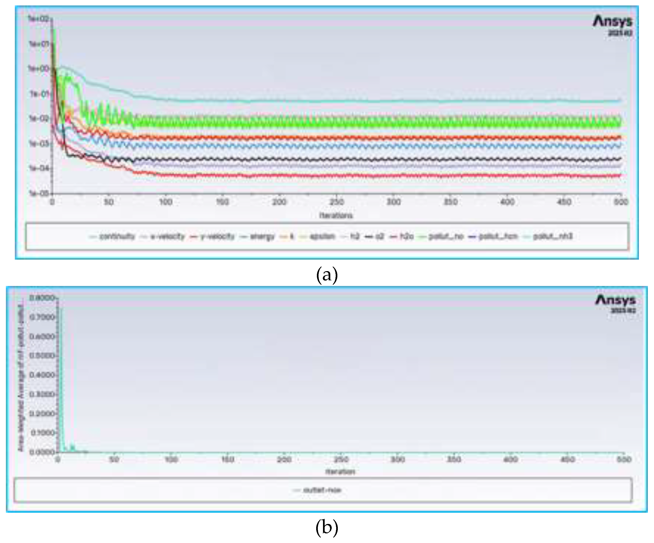
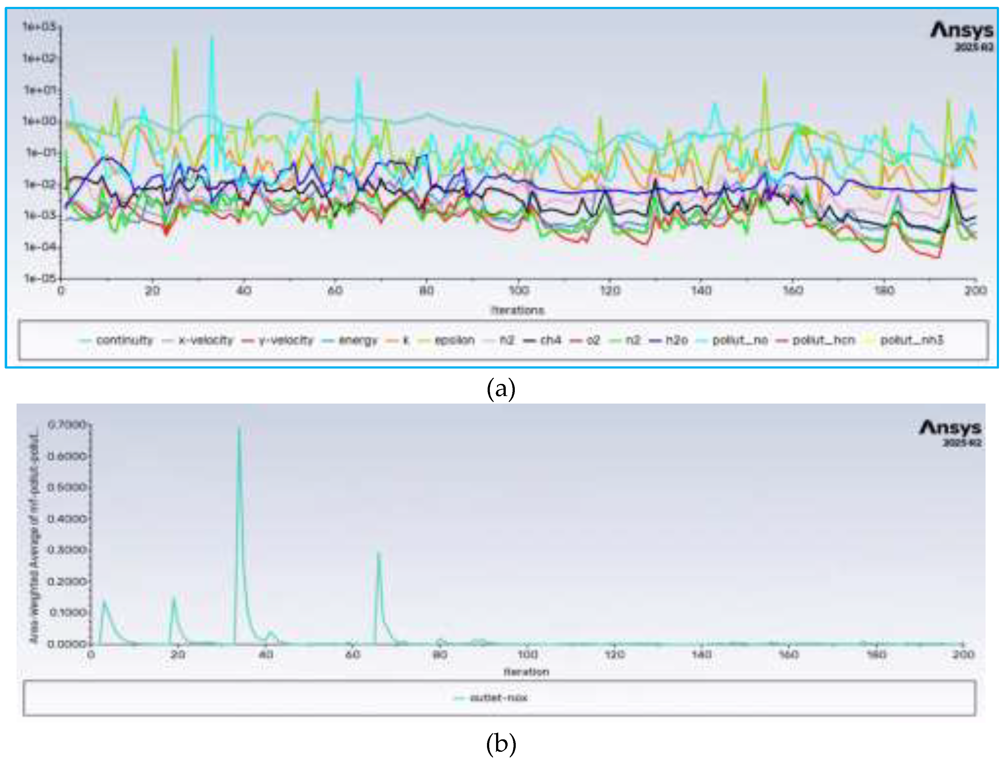
The focus on the pure hydrogen case of the residual chart indicates that the simulation history suggests a stable, well-converged reacting-flow solution. After an initial transient during the first ~50–80 iterations associated with flame establishment and strong coupling between energy, species transport, and turbulence of the residuals, they decay and settle into bounded oscillations. Continuity, momentum, energy, turbulence quantities (k–ε), and major species (H₂, O₂, H₂O) all reach residual levels below typical convergence thresholds (10⁻³–10⁻⁵), with no monotonic drift. The small, periodic oscillations observed at later iterations are characteristic of statistically steady turbulent combustion rather than numerical instability, indicating that the flame has stabilised and the solution has reached a physically meaningful steady state suitable for post-processing and emissions analysis.
Figure 10.
Ansys simulation of pure hydrogen lab combustor (a) simulation result of residual (b) simulation result of outlet-NOx chart.
Figure 10.
Ansys simulation of pure hydrogen lab combustor (a) simulation result of residual (b) simulation result of outlet-NOx chart.
The area-weighted average outlet NOₓ concentration in the figure decreases rapidly during early iterations and finally stabilises to a near-zero steady value after flame stabilisation. This behaviour demonstrates the absence of fuel-bound nitrogen in pure hydrogen combustion and the effective suppression of thermal NOₓ due to lean operation and rapid heat-release dilution. The flat profile at later iterations confirms that NOₓ formation has stabilised and is not affected by further solver progression, demonstrating that the emissions prediction is numerically consistent and physically governed by the set operating conditions.
The simulation predicts negligible NOₓ emissions at the combustor outlet, consistent with lean, hydrogen-fueled combustion where fuel-bound nitrogen is absent, and peak flame temperatures are moderated. The rapid convergence and stable near-zero NOₓ level indicate that thermal NOₓ formation is effectively suppressed under the selected operating conditions, consistent with published experimental and OEM findings for lean-hydrogen combustor concepts.
5.8.3. NOx Monitoring in Blended Hydrogen Gas Turbine
NOx was obtained from ANSYS Fluent as a mass fraction at the combustor outlet. The outlet NOx concentration was evaluated from node-based data and converted to ppmvd @ 15% O₂ using standard exhaust-gas normalisation procedures. The conversion assumes NO₂-equivalent molecular weight and accounts for water-vapour dilution and oxygen correction, consistent with OEM emissions reporting practice.
Figure 11 shows the residual histories for continuity, momentum, energy, turbulence (k–ε), major species, and pollutant scalars for all hydrogen-blended cases. While the residuals exhibit oscillatory behaviour, particularly for species and pollutant equations, this response is characteristic of strongly coupled reacting-flow simulations with radiation (P-1) and NOx sub-models, where temperature-sensitive source terms introduce stiffness and transient feedback. Importantly, the residual envelopes remain bounded and statistically stationary after the initial transient period, and integral outlet quantities (temperature and NOx) reach a stable mean over the final iterations, indicating numerical convergence in the sense relevant for emissions evaluation. Using the converged outlet NOx mass fraction, CFD-predicted NOx was converted to ppmvd @ 15% O₂ and overlaid against a relative thermal-NOx index defined as per equation in section 3.1, for all hydrogen fractions.
The overlay demonstrates a consistent monotonic correspondence: cases with higher index values yield higher CFD-predicted NOx, while increasing the hydrogen fraction and operating under progressively leaner conditions reduce the index and the corresponding ppmvd levels when peak temperatures are sufficiently suppressed. This agreement confirms that the analytical NOx index captures the dominant thermal-NOx sensitivities to combustor exit temperature and excess air ratio, providing a robust cross-case validation of the CFD trends across 0–30–50–70–100% H₂ operation, despite residual oscillations inherent to reacting-flow simulations.
5.9. Outlet Temperature Monitoring in Simulation
The combustor outlet temperature was evaluated using area-weighted surface integrals at the exit plane, providing a representative turbine inlet temperature for comparison with system-level models. Rather than suppressing the adverse pressure gradient generated by the high-momentum air stream, the study explicitly quantified fuel–air momentum interaction through jet-to-crossflow analysis. This enabled systematic evaluation of injector sizing and fuel distribution strategies, particularly for hydrogen-rich blends where volumetric flow requirements and momentum matching become critical.
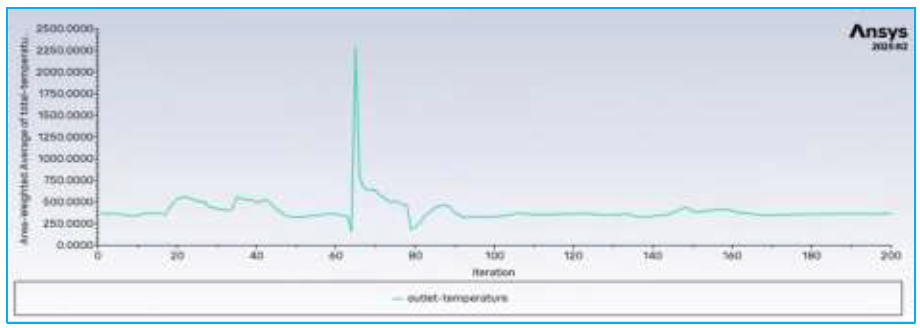
The combustor outlet temperature was monitored throughout the simulation using an area-weighted average static temperature measured at the outlet plane. This metric offers a representative surrogate for turbine inlet temperature (T₄) in simplified combustor CFD models and aligns with common practices in gas-turbine combustion research. The outlet temperature initially fluctuates as the coupled flow, turbulence, species transport, and energy equations establish a steady solution. A transient temperature spike occurs during the intermediate stage, reflecting an adjustment in energy balance after fuel–air mixing and heat release stabilisation. These overshoots are common in reacting-flow simulations and do not indicate divergence if followed by stabilisation.
After this phase, the temperature converges to a quasi-steady value with reduced oscillations, indicating a balance among fuel energy, convection, and diffusion. The lack of large fluctuations confirms the solution has reached a steady state suitable for analysis. The trend shows that a 30% hydrogen–70% methane blend can produce a stable thermal output in the simplified combustor under lean conditions. The smooth convergence validates the turbulence and combustion models used for hydrogen-enriched gas-turbine simulations without artefacts. The final temperature was used for comparison across different hydrogen ratios and system validation.
Figure 12.
Outlet temperature monitoring chart (a) simulation result of pure hydrogen (b) simulation result of blended hydrogen.
Figure 12.
Outlet temperature monitoring chart (a) simulation result of pure hydrogen (b) simulation result of blended hydrogen.
5.9. Conclusions and Future Research
This research examined hydrogen flame behaviour across three combustion configurations: non-premixed, premixed, and premixed-staged combustor, which was analysed over five hydrogen fractions (0%, 30%, 50%, 70% and 100%), using a simplified geometry, with a system-level modelling framework supported by Aspen HYSYS and targeted CFD interpretation with Ansys Fluent. The results show that non-premixed combustion offers the highest inherent flashback resistance. In contrast, a premixed stage with lower flashback resistance exhibits higher NOₓ potential and limited efficiency gains, making it unsuitable for sustained high hydrogen fractions beyond early exploratory studies.
Fully premixed combustion provides improved efficiency and lower NOₓ at low to moderate hydrogen blends; however, as hydrogen fractions increase, the approach becomes increasingly sensitive to flame speed, mixing uniformity, and flashback constraints. Research findings to develop a premixed-staged combustor that will be more protective against flashback and provide uniform flame stability. In contrast, the premixed-staged configuration emerges as the most robust solution for the current research scope, particularly in the 30–70% hydrogen blending range, as it balances lean operation, stable flame anchoring, and controllable heat release while maintaining acceptable operability margins. This finding is consistent across the three OEM combustion philosophies benchmarked, confirming that staged lean strategies are the most suitable near-term pathway for hydrogen co-firing in industrial gas turbines.
5.9.1. Blending Hydrogen Case
Future research on hydrogen blending should focus on refining the operability envelope and optimisation of co-firing strategies within the 30–70% hydrogen range validated in this study. While system-level results demonstrate stable performance at constant power, further work is required to quantify emissions sensitivity, air–fuel scheduling margins, and transient response under realistic load-following conditions. Coupled Aspen–CFD approaches could be used selectively to assess mixing quality and local equivalence ratio distributions in representative DLE, DLN, and micromix burners without fully resolving flame-scale chemistry. In addition, integrating economic and reliability considerations such as fuel supply variability, hydrogen availability, and maintenance impacts would strengthen the assessment of hydrogen blending as a near-term, deployable decarbonisation pathway for industrial and offshore gas turbines.
5.9.2. Pure Hydrogen 100% Case
The 100% hydrogen-firing case examined in this study is deliberately positioned as an exploratory research step rather than a direct reflection of current commercial gas turbine operation. Unlike the 30–70% hydrogen co-firing scenarios, which are validated against existing OEM hydrogen-ready combustion envelopes, operating entirely on hydrogen introduces a fundamentally different combustion regime with significantly altered flame speed, ignition characteristics, and operability constraints. As a result, modelling the 100% hydrogen case in Aspen HYSYS aims to establish baseline thermodynamic behaviour, system-level trends, and sensitivity limits that guide future combustor and system development.
From a modelling perspective, the 100% hydrogen case reveals the upper-bound response of the gas turbine cycle to extreme fuel reactivity and low volumetric energy density. The Aspen results indicate substantial redistribution of fuel and air flow requirements to maintain constant turbine inlet temperature and power output, alongside heightened sensitivity to air–fuel ratio control. These outcomes are consistent with known hydrogen combustion physics: hydrogen’s high laminar flame speed and short ignition delay drastically reduce tolerance for local equivalence ratio fluctuations. In contrast, its low molecular weight and high diffusivity impose additional demands on fuel delivery and mixing systems. At the system level, however, the cycle remains thermodynamically coherent, demonstrating that Aspen HYSYS can still close the mass and energy balances under full hydrogen firing, even if burner-scale feasibility is not implied.
Crucially, this study treats the 100% hydrogen case as a conceptual boundary condition rather than a validation point. The results are used to identify where conventional lean premixed or staged combustion assumptions break down, and where alternative strategies such as micromix burners, diffusion-stabilised hydrogen flames, or hybrid concepts become necessary. By isolating 100% hydrogen case from the OEM-validated co-firing range, the research maintains methodological integrity while still providing valuable insight into future hydrogen-only gas turbine pathways. In this sense, the 100% hydrogen analysis serves as a research hypothesis generator: it highlights the scale of fuel-flow changes, control sensitivity, and operability challenges that must be addressed before whole hydrogen operation can transition from laboratory and pilot systems to industrial or offshore deployment.
The 100% hydrogen case is presented not as a validated operating condition, but as a first-step research exploration intended to identify system-level trends, constraints, and future design requirements for hydrogen-only gas turbines. This future work builds directly on the validated co-firing analysis by progressing from system-level feasibility toward burner-resolved, dynamically operable, and offshore-deployable hydrogen-only gas turbine concepts.
5.9.3. Future Hybrid Design Approach for Micro Mixer
In the initial design configuration, hydrogen injection through six 12.5 mm ports resulted in low jet velocities (<10 m/s), insufficient for momentum-driven staged mixing. To align with literature-reported practice for hydrogen staging, the injector concept was revised to employ multiple smaller jets, achieving jet velocities on the order of 100 m/s. This preserves the per-cup hydrogen mass flow from the 15-cup annular Aspen model while ensuring realistic jet-in-crossflow mixing and flame-stabilisation behaviour. However, this article will focus on the hydrogen flame state and the two stages at which length can slow hydrogen flow, thereby preventing flashback.
For Micro-mixing, it is equipped with multiple small-scale fuel-injection ports that rapidly mix fuel and air at the microscale before ignition, without forming a fully premixed mixture upstream. This partially premixed approach enables safe handling of hydrogen or fast-reacting blends, thereby avoiding the high flashback risk associated with fully premixed systems. Micro-mixing burners limit residence time before ignition, restrict flashback pathways, and reduce local stoichiometric zones, thereby lowering NOx emissions. This strategy is now central to hydrogen-ready engines for hydrogen-LNG blends; micro-mixing provides an ideal balance between NOx reduction, stability, and safety. Advanced DLE (Dry Low Emission) is an ongoing research effort aimed at achieving lean premixing, dilution jets, and sufficient mixing time to manage high flame speeds and mitigate flashback, thereby preventing hot spots and NOx spikes. [
33,
34]
5.9.4. Future NOx Reduction Methodology
Most gas turbine OEMs have made progressive efforts to improve NOx control for hydrogen-fueled gas turbines, with the key being post-combustion NOx treatment. Current R&D efforts are underway to develop the Micro-Mix combustor (MMX) to improve hydrogen combustion stability and reduce NOx formation. The challenge is to design a 100% hydrogen-fuelled gas turbine with low NOx levels, emphasising extensive R&D to develop effective NOx abatement techniques and improve combustor performance. However, the studies presented in this paper have demonstrated that a fully commercialised pure hydrogen turbine will be created within the next century, with sufficient R&D details. [
35,
36]