
Submitted:
11 February 2026
Posted:
12 February 2026
You are already at the latest version
Abstract
An alternative MEMS navigation method for determining latitude, longitude, and altitude is proposed, based on Velocity-Aided Navigation, when global navigation satellite system (GNSS) or Starlink signals are unavailable for various reasons. Currently, GNSS receivers are the primary navigation systems that meet consumer demand for location accuracy. However, GNSS receivers are not autonomous and are susceptible to jamming and spoofing. Strapdown inertial navigation systems (SINS), unlike GNSS, are autonomous. Their operating principle is based on double integration of accelerometer output signals. However, they have a significant drawback: SINS errors increase significantly over time. Two approaches are used to improve accuracy. The first involves using expensive, high-precision gyroscopes and accelerometers. The other involves correcting the SINS by integrating it with navigation systems built on physical principles different from those of the SINS. An alternative method based on MEMS IMU for determining navigation parameters is proposed that does not require double integration of accelerometer output signals. Analytical expressions for the errors of the new method are derived. Calculations showed that the errors of the new method are significantly smaller than those of the SINS. Experimental testing confirmed the calculation results and demonstrated that the errors of the new method are comparable to those of the SINS integrated with GNSS and a Kalman filter. The proposed alternative NEMS navigation method for determining latitude, longitude, and altitude can be used independently, as an alternative to GNSS for integration with the SINS, and can also serve as a backup navigation system.
Keywords:
MEMS
; SINS
; GNSS
; IMU
; latitude
; longitude
; altitude
; gyroscopes
; accelerometers
; velocity aided navigation
1. Introduction
Today, global navigation satellite system (GNSS) receivers are arguably the primary navigation systems, achieving high accuracy (with errors of 1-2 cm) in determining location coordinates. Unfortunately, GNSS are not autonomous navigation systems, as they depend on the operation of a satellite constellation. This operation can be affected by various natural and artificial factors [1]. Unlike GNSS, strapdown inertial navigation systems (SINS) are autonomous. Their operating principle is based on double integration of accelerometer readings. Since the accelerometer output signal contains errors in addition to the useful signal, after integration, the SINS errors increase nonlinearly with time (as will be shown below, proportional to the square of time for accelerometer errors and the cube of time for gyroscope errors). To correct SINS operation, they are integrated with navigation systems built on physical principles different from those of SINS. For example, they are often integrated with GNSS. However, after such integration, such navigation systems cease to be autonomous. Another way to reduce INS errors is to use expensive, high-precision gyroscopes and accelerometers. However, this significantly increases the cost of such SINS. Such SINS are used in space missions or for military purposes.
UAVs and autonomous systems increasingly operate in GPS-denied or contested areas, necessitating robust standalone navigation capabilities. The foundational principles for addressing these challenges were established by Titterton and Weston [2], who rigorously described the physics of "strapdown" systems—where sensors are rigidly attached to the vehicle—and derived the direction cosine matrix and quaternion equations necessary to resolve body-frame measurements into a stable navigation frame. However, low-cost MEMS sensors suffer from inherent errors like bias instability, causing position drift to grow rapidly over time. While Global Navigation Satellite Systems (GNSS) typically correct this drift, recent studies have quantified their acute vulnerability; for instance, Sushych et al. exposed multi-constellation receivers to continuous wave and swept-frequency interference, demonstrating that even sophisticated systems suffer rapid "lock loss" and signal degradation under low-power jamming [3]. Consequently, modern research focuses on three critical areas: enhancing sensor precision, refining filtering logic, and implementing intelligent data fusion.
1.1. Improving the Accuracy of SINS Sensing Elements
Mitigating sensor errors at the source is the first line of defense. Research now emphasizes dynamic modulation, neural-network-enhanced calibration, and array-based processing.
Rotation Modulation (RM): Originally developed for strategic-grade systems, RM is now being adapted for low-cost MEMS. Sharifi and Eslami [4] demonstrated a single-degree-of-freedom (DoF) rotary system that mechanically modulates constant sensor errors into zero-mean sinusoidal signals; this rotation effectively cancels out bias, scale factor, and misalignment errors around the body's horizontal axes. Further analysis by Li et al. [5] investigated the residual effects of "slow-varying" errors that persist during rotation. They confirmed that modified dual-axis continuous rotation schemes outperform simple rotation-stop combinations by effectively "averaging out" these drift components, preventing error integration during long-endurance missions.
Advanced Calibration: Traditional static calibration is being replaced by learning-based and analytical methods. Zhang and Wang [6] introduced a Wavelet Threshold Back-Propagation Neural Network (WT-BPNN) that decomposes sensor signals to separate noise from drift. By modeling the non-linear random drift characteristics, their method achieves a 12 dB improvement in zero-bias instability. For environmental robustness, Kim and Jung [7] successfully applied Radial Basis Function (RBF) networks to model the complex non-linear "memory" effects of thermal hysteresis, reducing thermal drift by up to 63% in dynamic temperature environments. Additionally, Rupniewski [8] proposed a Singular Value Decomposition (SVD) method that provides a closed-form algebraic solution for sensor misalignments. This approach eliminates the need for iterative Gauss-Newton solvers, operating three orders of magnitude faster while maintaining equivalent precision.
IMU Arrays: To overcome individual sensor noise floors, high-density arrays are employed. Sawada et al. [9] achieved "navigation-grade" performance using a 32-sensor array on a single device; they developed an analytical method to model and subtract mechanical crosstalk, allowing the array to fully realize the theoretical noise reduction. Lin et al. [10] advanced this by applying array signal processing—similar to radar techniques—to spatially filter interference and dynamically suppress outlier sensors using FPGA hardware. Zhu et al. [11] utilized the Fruit Fly Optimization Algorithm (FOA) to determine optimal weighting coefficients for sensor fusion. Rather than simple averaging, the FOA iteratively searches for the weight distribution that minimizes global error, significantly reducing Angle Random Walk (ARW).
1.2. SINS Algorithms: Variations of the Kalman Filter
Standard Extended Kalman Filters (EKF) struggle with non-Gaussian noise and high dynamics. Recent innovations focus on entropy-based, adaptive, and decentralized architectures.
Non-Linear and Higher-Order Filtering: Liu et al. [12] proposed the Adaptive Minimum Error Entropy Cubature Kalman Filter (AMEECKF). By minimizing the entropy (disorder) of the error distribution and employing a kernel bandwidth adjustment factor, this filter offers superior robustness to non-Gaussian outliers common in UAV flight data. Similarly, Bai and Li [13] and Dai et al. [14] introduced Adaptive Gaussian Sum Cubature Kalman Filters (AGSCKF). These filters model complex noise as a weighted sum of multiple Gaussians and use a cost function-based adaptation to optimize the mixture parameters in real-time, effectively handling time-varying noise profiles. For embedded stability, Yang et al. [15] validated an Adaptive Square-Root Cubature Kalman Filter (SR-CKF). By propagating the square root of the covariance matrix to ensure numerical stability, they achieved a 0.081m median localization error in dark, GPS-denied environments.
Robust and Adaptive Strategies: To manage high-intensity maneuvers, Chen et al. [16] developed an improved fading factor algorithm. This framework uses multi-source data—incorporating PDOP and satellite count—to automatically inflate process noise during maneuvers, preventing the filter from lagging behind the vehicle's actual trajectory. Xie and Dai [17] presented an adaptive robust Maximum Correntropy Criterion (MCC) filter. By using a fixed adaptive kernel bandwidth, the MCC method effectively saturates and caps large error terms caused by multipath effects in urban environments. Additionally, Majewski and Zugaj [18] demonstrated an Adaptive Kalman Filter (AKF) that dynamically adjusts process noise covariance based on real-time maneuver detection, utilizing residual analysis to tighten tracking during aggressive turns.
Federated and Decentralized Filtering: For multi-sensor reliability, Zhan et al. [19] introduced "Dimensional Isolation" in Federated Kalman Filters. This utilizes a Chi-square-based adaptive thresholding mechanism to detect local sensor faults and isolate them, preventing a single failing sensor from corrupting the master global solution. Xu and Huang [20] and Yan and Yang [21] enhanced this architecture with Variational Bayesian (VB) inference. The VB approach allows for the joint estimation of the vehicle state and time-varying noise parameters, improving robustness against complex, fluctuating measurement noise. Zhu et al. [22] further integrated fuzzy inference to adjust information-sharing coefficients, allowing the system to smoothly de-weight data from degrading sensors based on real-time fault detection.
1.3. Alternative Architectures and Intelligent Fusion
The field is increasingly moving toward Factor Graph Optimization (FGO) and deep learning to overcome the limitations of recursive filtering.
Factor Graph Optimization (FGO): Ning et al. [23] utilized FGO with P-Splines to smooth Doppler measurements and reconstruct predictive observation factors. By optimizing the entire trajectory globally rather than sequentially, they improved northward accuracy by 35% in urban canyons. Dome et al. [24] validated FGO for multi-GNSS/IMU integration, showing that maintaining historical connectivity between states allows FGO to recover more information from sparse data, achieving a 56.71% increase in accuracy over EKF-based smoothers. Suzuki [25] lowered the barrier to entry by releasing gtsam_gnss, an open-source package that leverages the GTSAM library to facilitate robust GNSS/IMU integration, enabling decimeter-level accuracy on standard smartphones.
Deep Learning and SciML: Irfan et al. [26] proposed the LSAF-LSTM framework, which uses a Long Short-Term Memory (LSTM) network to dynamically compute sensor fusion weights. The LSTM analyzes historical data patterns to assess environmental reliability in real-time, adapting the fusion logic to current conditions. Jeong et al. [27] developed an integrated localization architecture that uses LSTMs to assess "latent vectors" from auxiliary pose estimators. By learning to filter these compressed feature representations, they reduced average position RMSE by 79–91% compared to traditional VIO baselines. Transformers are also emerging, with Abdulmaksoud [28] reviewing their utility for attention-based fusion, and Kuchkin et al. [29] demonstrating that transformer-based dense perception can effectively identify and mask dynamic objects (like moving machinery), allowing SLAM systems to maintain lock on static structures in cluttered industrial scenes.
Visual and Bio-Inspired Navigation: Li et al. [30] developed "DeepLine-VIO," which extracts illumination-invariant line features via an attraction-field-based deep network. This approach is far more robust than point-feature methods in low-texture environments, reducing Absolute Trajectory Error (ATE) by up to 15.87%. Kühne et al. [31] implemented VIO using on-sensor hardware acceleration for optical flow. By calculating motion vectors directly on the image sensor, they achieved a 49.4% reduction in latency and a 53.7% reduction in compute load, enabling 50 FPS operation on resource-constrained microcontrollers. Bio-inspired strategies are also maturing; Wang et al. [32] integrated a polarization compass that mimics insect navigation. Using a Chi-square test to detect magnetic anomalies, the system switches to the polarization heading reference in magnetic-denied environments. Agarwal et al. [33] furthered this by using SVM-based parameter tuning to classify sky conditions, ensuring accurate solar azimuth prediction under both clear and cloudy skies.
Collaborative Swarm Navigation: Zhang et al. [34] proposed a collaborative integrated navigation framework for UAV swarms that accounts for multiple uncertainties via statistical linearization, allowing drones to refine their positions by sharing relative ranging data. Arshid et al. [35] and Czaja and Maslanka [36] reviewed trajectory design paradigms and mutual localization techniques, highlighting that game-theory-based coalition formation and distributed consensus filtering are essential for maintaining swarm resilience without a central point of failure.
Velocity Aided Navigation: In environments like the deep ocean where GNSS is absent, navigation relies on integrating SINS with velocity sensors such as the Doppler Velocity Log (DVL). Pan and Wu [37] addressed the challenges of SINS/DVL integration through observability analysis; they proved that specific vehicle maneuvers render DVL scale factor and misalignment errors observable, enabling in-situ self-calibration without external references. When equipment limitations or terrain issues lead to partial signal loss, Tal, Klein, and Katz [38] demonstrated an Extended Loosely Coupled (ELC) approach that constructs "virtual beams" based on physical constraints (e.g., zero sway velocity), maintaining a stable solution even with fewer than three active acoustic beams. For more seamless resilience, Cohen and Klein [39] introduced "BeamsNet," a deep learning framework that regresses missing beam measurements from inertial data, outperforming baseline model-based approaches by 96.15% in velocity accuracy during DVL outages.
This paper proposes the implementation of a Velocity Aided Navigation (VAN) method and MEMS IMU, which operates by leveraging vehicle velocity sensors.
2. Statement of the problem
Let's consider a geographic coordinate system (ENU), as shown in Figure 1.
The following notations are introduced here: is a longitude, is a latitude, is a radius of the Earth; h is a flight altitude; Ω is an angular velocity of the Earth's rotation; are projections of the speed of movement of an object v onto the corresponding axes; H is a heading.
We can obtain the basic equations of inertial navigation from Figure 1:
By integrating equation (1) over time, we can obtain the current values of latitude, longitude, and altitude. To do this, we need to have the velocity projections. . Let us first consider the standard inertial method.
3. Inertial method for determining velocity projections
First, let us consider obtaining projections of the object's velocity using the inertial method or the standard method of classical SINS using accelerometers.
To obtain current values , projections of the object's specific forces onto the axes of the geographic coordinate system are used. Derivatives of or projections of the object's acceleration onto the axes of the geographic coordinate system can be obtained from the full expressions for the projections of the accelerometers' specific forces (2):
Since accelerometers are mounted on the object, they measure accelerations relative to the axes associated with the object, not the axes of the geographic coordinate system. Let's establish a relationship between the axes of the geographic coordinate system and the coordinate system associated with the object, Oxyz. Let's denote the object's rotation angles (yaw, pitch, roll) relative to the geographic coordinate system by (Figure 2).
For a given sequence of rotations, the direction cosine matrix of the transition from the coordinate system to will have the form:
There is a relationship between the projections of the specific forces on the axes and :
here is a transposed matrix .
To find the matrix elements , it is necessary to solve the orientation problem, i.e., determine the angles . The orientation problem can be solved using Euler's kinematic equations, generalized Poisson equations, quaternions, or the finite Euler rotation angle.
Now, knowing the orientation angles, and therefore the matrix elements , we can calculate the current latitude, longitude, and altitude using expressions (1), given the latitude, longitude, and altitude values from the previous step. For the first step of the calculations, we need to know the initial coordinates of the location.
4. Dependence of SINS Errors on the Errors of Accelerometers and Gyroscopes
From the fundamental equations of inertial navigation, by expansion into a Taylor series, we can obtain the systematic errors of the SINS. To do this, we first calculate the derivatives of expressions (1):
We find the derivatives from expressions (2) and substitute them into relations (5):
Let the matrix have the following form:
From the matrix equation (4) we obtain the required projections and substitute them into equations (6), which we then represent in the following form:
Here functions Fφ,Fλ,Fh are right-hand sides of equations (6).
We will look for the systematic errors of the SINS, which depend on the systematic errors of the accelerometers and gyroscopes, by expanding the relations into a Taylor series (8):
here is an error in determining longitude, is a latitude determination error; Δh is an altitude determination error; are systematic errors of accelerometers; are the projections of specific forces onto the axes of the Oxyz coordinate system associated with the object.
Omitting cumbersome transformations and double integration, we present expressions for the systematic errors of the SINS:
here are systematic errors or drifts of gyroscopes; are the projections of the UAV's angular velocity onto the axes associated with the object, measured by three gyroscopes; t is a time. Here the projections of the specific forces onto the axes of the geographic coordinate system are related to by the relation (11):
It is evident that the errors of the SINS, except for the first term in (10), depend on the actual values of acceleration and angular velocity of the object.
In addition to systematic components, gyroscopes and accelerometers are characterized by random errors of the Angular Random Walk (ARW) [rad/s/] and Velocity Random Walk (VRW) [m/s2/] types, respectively. It can be shown that these errors lead to standard deviation errors of the SINS:
An analysis of the SINS error expressions (10) and (12) reveals a dramatic time dependence. To address this drawback, various types of SINS corrections are used from navigation systems built on other physical principles. The most common such navigation systems currently are GNSS satellite navigation systems. However, integrating SINS with GNSS results in the integrated system's dependence on the operation of the satellite navigation system, which can be unstable in adverse conditions, such as urban canyons in modern cities, signal loss from satellites, etc. In this case, an alternative method based on Velocity Aided Navigation using MEMS IMU gyroscopes is proposed.
5. Determining Latitude, Longitude, and Altitude Using Velocity Aided Navigation
Velocity Aided Navigation is based on equations (13):
here v, vς are the horizontal and vertical components of the object's velocity.
While accelerometers are used to determine the object's velocity for SINS, Velocity Aided Navigation uses Doppler radar, Pitot tubes, and optical sensors such as lasers as velocity meters in aviation. Doppler Velocity Log (DVL) is used at sea, and Wheel Odometer with an encoder is used for land vehicles. Despite their different operating principles, they all share the commonality of measuring relative velocity.
By integrating expressions (13), we obtain the current latitude, longitude, and altitude values, knowing the object's current velocity and heading, as well as the latitude, longitude, and altitude values from the previous step. For the first step of the calculation, we need to know the initial coordinates of the location.
From equations (13), by expanding them into a Taylor series, we obtain the systematic errors of VAN, which depend on the systematic errors of the velocity sensors and gyroscopes:
here Δv, ΔVς are the systematic errors of horizontal and vertical velocity measurements.
It is obvious that the errors of the VAN+IMU system, except for the first term in (14), depend on the actual values of the linear velocity and angular velocity of the object.
In addition to systematic components, horizontal and vertical velocity measurements are characterized by random errors of the Position Random Walk (PRW) type [m/s/ ]. It can be shown that these errors lead to standard deviation errors of the VAN+IMU:
Table 1 presents the numerical characteristics of the errors of MEMS gyroscopes and accelerometers, as well as velocity meters.
Figure 3, Figure 4 and Figure 5 show the calculation results for the errors SINS – a) and VAN – b) for 65 sec in the following form:
here , are the total errors and their components; p=x,y,z;
; i=1 – systematic bias of accelerometers and a coefficient; i=2 – systematic bias of gyroscope and a coefficient ; i=3 – systematic bias of gyroscope and a coefficient ; i=4 – random bias of accelerometers and a coefficient ; i=5 – systematic bias of gyroscope and a coefficient ; i=6 – systematic bias of gyroscope and a coefficient .
Also, the actual values of the acceleration, linear velocity and angular velocity of the object from flight data described in item 5 below, were used for calculations (16).
As can be seen from the figures, the errors of this method for the X and Y coordinates over a period of 65 seconds are significantly less than those of the inertial method.
6. Results of Experimental Testing of VAN+IMU and SINS+GNSS Operation
To test the effectiveness of the developed method for autonomously determining latitude and longitude, experimental INS data obtained during a flight on a small Cessna aircraft near Orlando, Florida, USA, was used. This data included information on the aircraft's heading, pitch, and roll angles, angular velocity, specific forces, latitude, longitude, and altitude measured by a global navigation system (GNSS) receiver, as well as information on the horizontal and vertical components of the aircraft's velocity and the current time.
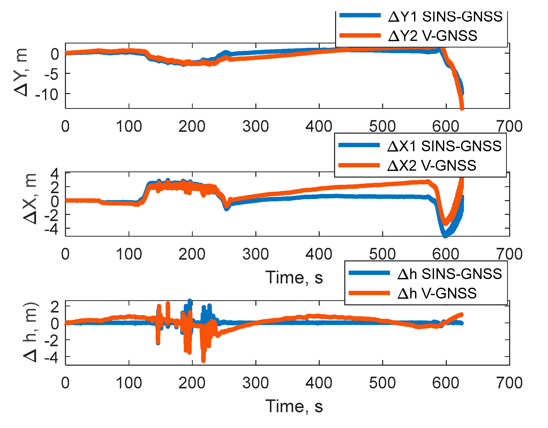
Figure 6, Figure 7, Figure 8, Figure 9, Figure 10 and Figure 11 show the graphical dependences of latitude, longitude, and altitude over time, and the error in determining linear coordinates over time for three flight segments. The following notations are used in the figures: the GNSS curve represents the latitude, longitude, and altitude values measured using a GNSS receiver; the SINS KF curve represents the latitude, longitude, and altitude values calculated using the SINS algorithms integrated with GNSS using the Kalman filter; and the v curve represents the latitude, longitude, and altitude values calculated using the proposed VAN+IMU algorithms. The SINS-GNSS curve represents the error between the integrated SINS and GNSS information; and the v-GNSS curve represents the error between the VAN+IMU signals and GNSS information.
The results of the experimental testing of the operation of VAN+IMU and SINS+GNSS for the 1st section lasting 65 seconds are shown in Figure 6 and Figure 7.
From Figure 6 it can be seen that the latitude, longitude and altitude angles measured using the GNSS receiver, the latitude, longitude and altitude values calculated using the SINS algorithms integrated using the Kalman filter with GNSS and the latitude, longitude and altitude values calculated using the proposed VAN+IMU algorithms are almost identical.
From Figure 7, it can be concluded that the errors in determining linear coordinates have a maximum value of 50 m for the X coordinate. For height, the error does not exceed one meter.
The results of the experimental testing of the operation of VAN+IMU and SINS+GNSS for the 2nd section lasting 200 seconds are shown in Figure 8 and Figure 9.
From Figure 8 it can be seen that the latitude, longitude and altitude angles measured using the GNSS receiver, the latitude, longitude and altitude values calculated using the SINS algorithms integrated using the Kalman filter with GNSS and the latitude, longitude and altitude values calculated using the proposed VAN+IMU algorithms are practically the same.
From Figure 9, we can conclude that the errors in determining linear coordinates have a maximum value of 2 meters for the X and Y coordinates. For altitude, the error does not exceed 4 meters.
The results of the experimental verification of the VAN+IMU and SINS+GNSS systems for the third segment, lasting 700 seconds, are shown in Figure 10 and Figure 11.
From Figure 10 it can be seen that the latitude, longitude and altitude values measured using the GNSS receiver, the latitude, longitude and altitude values calculated using the SINS algorithms integrated using the Kalman filter with GNSS and the latitude, longitude and altitude values calculated using the proposed VAN+IMU algorithms are almost identical.
From Figure 11, it can be concluded that the errors in determining linear coordinates have a maximum value of 10 m for the X and Y coordinates. For height, the error does not exceed 6 meters.
7. Conclusions
The use of VAN is proposed as an alternative method for determining navigation parameters such as latitude, longitude, and altitude in the absence of GNSS/Starlink signals. Extended analytical dependencies of systematic and random errors over time are obtained for the standard SINS and the alternative method. Error calculations under real-world operating conditions show that the errors of the new method are significantly lower than those of the SINS. To experimentally test a new method for autonomously determining latitude and longitude, experimental flight data from a small Cessna aircraft were used. This data included the output signals of three MEMS gyroscopes, three MEMS accelerometers, latitude, longitude, and altitude information measured by a global navigation system (GNSS) receiver, as well as horizontal and vertical velocity data and the current time. Based on flight data, attitude angles, current latitude, longitude, and altitude, as well as linear coordinate determination errors, calculation were performed. In addition, current latitude, longitude, and altitude values were calculated using SINS algorithms with a Kalman filter. The results of calculations based on experimental data demonstrate the effectiveness of the proposed method. Thus, for the first flight segment, which lasted 65 s, the errors in determining the linear coordinates of the alternative VAN+IMU method were at the level of errors using the SINS with GNSS correction using the Kalman filter and did not exceed 50 m. For the other two flight segments, lasting 200 s and 600 s, the errors in determining the linear coordinates of the alternative VAN+IMU method were again at the level of errors using the SINS with GNSS correction using the Kalman filter and did not exceed 10 m. Thus, the proposed method for determining navigation parameters using VAN+IMU speed can be used as an alternative for UAVs when GNSS/Starlink signals are unavailable.
References
- Schmidt, G.T. GPS Based Navigation Systems in Difficult Environments. Gyroscopy Navig. 10, 41–53 (2019).
- Titterton D. H. and Weston J. L. Strapdown Inertial Navigation Technology. - IEE Radar, Sonar, Navigation and Avionics Series 17, 2004. – pp. 558.
- Sushych, O.; Pogurelskiy, O.; Konin, V.; Kutsenko, O.; Prykhodko, I.; Maliutenko, T. Performance Analysis of Intentional Interference on Multi-GNSS Receivers. In Proceedings of the 2nd International Workshop on Advances in Civil Aviation Systems Development; Springer Nature: Switzerland, 2024; pp. 114–124.
- Sharifi, A.; Eslami, A. Implementation of a Single-Degree-of-Freedom Rotary Inertial Navigation System Based on Low-Cost Inertial Sensors. J. Space Sci. Technol. 2025, 13, e235319.
- Li, H.; Chen, S.; Wang, Y.; Ben, Y. Analysis of the Effect of Slow-Varying Errors on Rotary Modulation Systems. Sensors 2024, 24, 5025.
- Zhang, Y.; Wang, X. Hybrid Filtering Compensation Algorithm for Suppressing Random Errors in MEMS Arrays. Micromachines 2024, 15, 558.
- Kim, H.J.; Jung, H.K. Temperature Hysteresis Calibration Method of MEMS Accelerometer. Sensors 2025, 25, 6131.
- Rupniewski, M.W. SVD calibration of inertial sensors. Measurement 2025, 249, 117929.
- Sawada, T.; Amano, T.; Kimishima, M.; Sonoura, A.; Hongo, K.; Yamashita, K.; Kamata, H. An Ultra-Low Noise MEMS IMU Array Based on Analytical Interference Mitigation for Highly Accurate Inertial Navigation. In Proceedings of the 2025 IEEE International Symposium on Inertial Sensors and Systems (INERTIAL); IEEE: Kauai, HI, USA, 2025.
- Lin, J.; et al. MEMS Gyro Array Employing Array Signal Processing for Interference and Outlier Suppression. IEEE Sens. J. 2025, 25, 8880.
- Zhu, T.; Peng, G.; Li, J.; Xuan, J.; Tian, J. Fruit-Fly-Optimized Weighted Averaging Algorithm for Data Fusion in MEMS IMU Array. Micromachines 2025, 16, 739.
- Liu, X.; Zhao, H.; Liu, Y.; Ling, S.; Chen, X.; Yang, C.; Cao, P. Adaptive Minimum Error Entropy Cubature Kalman Filter in UAV-Integrated Navigation Systems. Drones 2025, 9, 740.
- Bai, L.; Li, C. A Novel Adaptive Gaussian Sum Cubature Kalman Filter with Time-Varying Non-Gaussian Noise for GNSS/SINS Tightly Coupled Integrated Navigation System. Front. Astron. Space Sci. 2025, 12, 1436270.
- Dai, Q.; Wan, R.; Han, S.Y.; Xiao, G.R. A novel adaptive Gaussian sum cubature Kalman filter with time-varying non-Gaussian noise for GNSS/SINS tightly coupled integrated navigation system. Front. Astron. Space Sci. 2025, 12, 1436270.
- Yang, B.; Yang, E.; Shi, H.; Yu, L.; Niu, C. Adaptive Square-Root Cubature Kalman Filter Based Low Cost UAV Positioning in Dark and GPS-Denied Environments. IEEE Trans. Intell. Veh. 2025, 10, 3587–3599.
- Chen, Z.; Liu, Y.; Liu, S.; Wang, S.; Yang, L. An Improved Fading Factor-Based Adaptive Robust Filtering Algorithm for SINS/GNSS Integration with Dynamic Disturbance Suppression. Remote Sens. 2025, 17, 1449.
- Xie, T.; Dai, Z. Adaptive robust maximum correntropy extended Kalman filter for GNSS navigation in urban areas. GPS Solut. 2025, 29, 188.
- Majewski, K.; Zugaj, M. Adaptive Kalman Filter for UAV Dynamic Flight Maneuvers. In Proceedings of the Research and Education in Aircraft Design (READ) Conference 2024; Warsaw, Poland, 2024.
- Zhan, Q.; Shen, R.; Mao, Y.; Shu, Y.; Shen, L.; Yang, L.; Zhang, J.; Sun, C.; Guo, F.; Lu, Y. Adaptive Federated Kalman Filtering with Dimensional Isolation for Unmanned Aerial Vehicle Navigation in Degraded Industrial Environments. Drones 2025, 9, 168.
- Xu, B.; Huang, Z. An Improved Variational Bayesian-Based Adaptive Federated Kalman Filter for Multi-Sensor Integrated Navigation Systems. Sensors 2025, 25, 7173.
- Yan, Y.; Yang, J. An Improved Variational Bayesian-Based Adaptive Federated Kalman Filter for Multi-Sensor Integrated Navigation Systems. Sensors 2025, 25, 7173.
- Zhu, Y.; Zhang, M.; Zhou, L.; Cai, T. A Novel Fault-Tolerant Information Fusion Method for Integrated Navigation Systems Based on Fuzzy Inference. Sensors 2025, 25, 1624.
- Ning, B.; Zhao, F.; Luo, H.; Luo, D.; Shao, W. Robust GNSS/INS Tightly Coupled Positioning Using Factor Graph Optimization with P-Spline and Dynamic Prediction. Remote Sens. 2025, 17, 1792.
- Dome, T.; Russell, T.; Rejon, M.O.; Zheng, Y.; Benedetti, E.; Li, T.; Sun, M.; Petrunin, I. Robust Multi-GNSS Navigation Using Factor Graph Optimization. In Proceedings of the ION GNSS+ 2025; Institute of Navigation: Denver, CO, USA, 2025.
- Suzuki, T. Open-Source Factor Graph Optimization Package for GNSS: Examples and Applications. arXiv 2025, arXiv:2502.08158.
- Irfan, M.; Dalai, S.; Trslic, P.; Riordan, J.; Dooly, G. LSAF-LSTM-Based Self-Adaptive Multi-Sensor Fusion for Robust UAV State Estimation in Challenging Environments. Machines 2025, 13, 130.
- Jeong, T.-H.; Lee, Y.-J.; Ahn, W.-J.; Kang, T.-K.; Lim, M.-T. Robust Vehicle Pose Estimation Through Multi-Sensor Fusion of Camera, IMU, and GPS Using LSTM and Kalman Filter. Appl. Sci. 2025, 15, 11863.
- Abdulmaksoud, A. Transformer-Based Sensor Fusion for Autonomous Vehicles: A Comprehensive Review. IEEE Access 2025, 13, 41823.
- Kuchkin, O.; Sazonov, A.; Cherepanska, I.; Zhuchenko, A. Transformer-Based Network for Robust 3D Industrial Environment Understanding in Autonomous UAV Systems. J. Energy Eng. Control Syst. 2025, 11, 210–216.
- Li, X.; Liu, C.; Yan, X. Robust Visual-Inertial Odometry with Learning-Based Line Features in a Illumination-Changing Environment. Sensors 2025, 25, 5029.
- Kühne, J.; Magno, M.; Benini, L. Low Latency Visual Inertial Odometry with On-Sensor Accelerated Optical Flow for Resource-Constrained UAVs. IEEE Sens. J. 2025, 25, 7838–7847.
- Wang, S.; Qiu, Z.; Huang, P.; Yu, X.; Yang, J.; Guo, L. A Bioinspired Navigation System for Multirotor UAV by Integrating Polarization Compass/Magnetometer/INS/GNSS. IEEE Trans. Ind. Electron. 2023, 70, 8526–8536.
- Agarwal, D.; Potter, B.; Siddiqui, J.Y.; Antar, Y.M.M.; Alam, M.Z. Bio-Inspired Polarization Compass for Solar Azimuth Prediction Under Clear and Cloudy Sky Conditions. IEEE Access 2025, 13, 10816422.
- Zhang, L.; Cao, X.; Su, M.; Sui, Y. Collaborative Integrated Navigation for Unmanned Aerial Vehicle Swarms Under Multiple Uncertainties. Sensors 2025, 25, 617.
- Arshid, K.; Krayani, A.; Marcenaro, L.; Gomez, D.M.; Regazzoni, C. Toward Autonomous UAV Swarm Navigation: A Review of Trajectory Design Paradigms. Sensors 2025, 25, 5877.
- Czaja, B.; Maślanka, K.S. Overview of Mutual Localization Techniques Between Unmanned Aerial Vehicles in Swarm. TransNav 2025, 19, 318.
- Pan, X.; Wu, Y. Underwater Doppler Navigation with Self-calibration. Journal of Navigation 2016, 69, 295–312.
- Tal, A.; Klein, I.; Katz, R. Inertial Navigation System/Doppler Velocity Log (INS/DVL) Fusion with Partial DVL Measurements. Sensors 2017, 17, 415.
- Cohen, N.; Klein, I. Seamless Underwater Navigation with Limited Doppler Velocity Log Measurements. arXiv 2024, arXiv:2404.13742.
Figure 1.
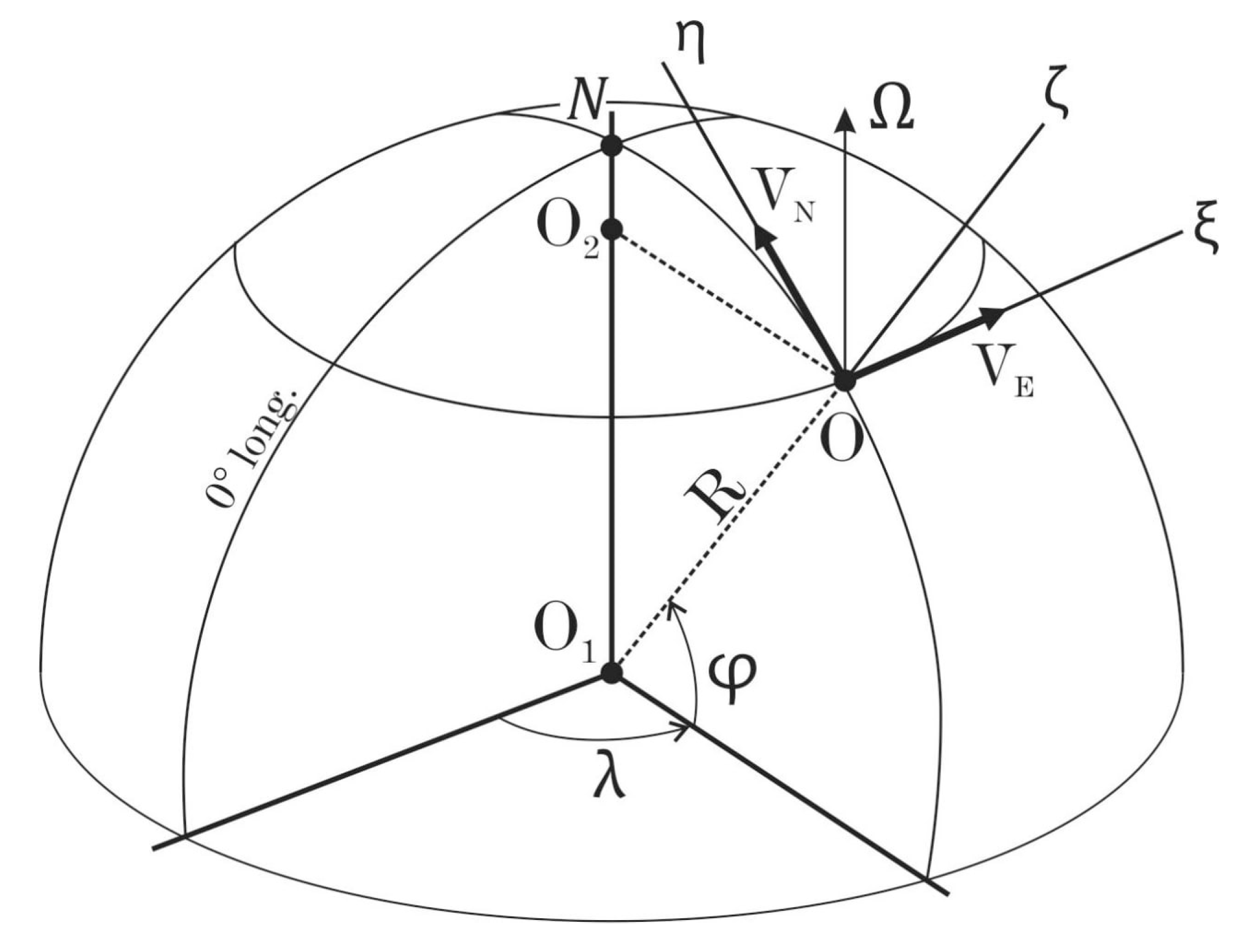
Figure 2.
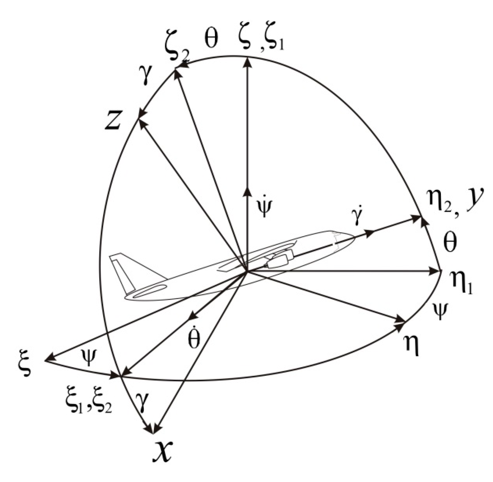
Figure 3.
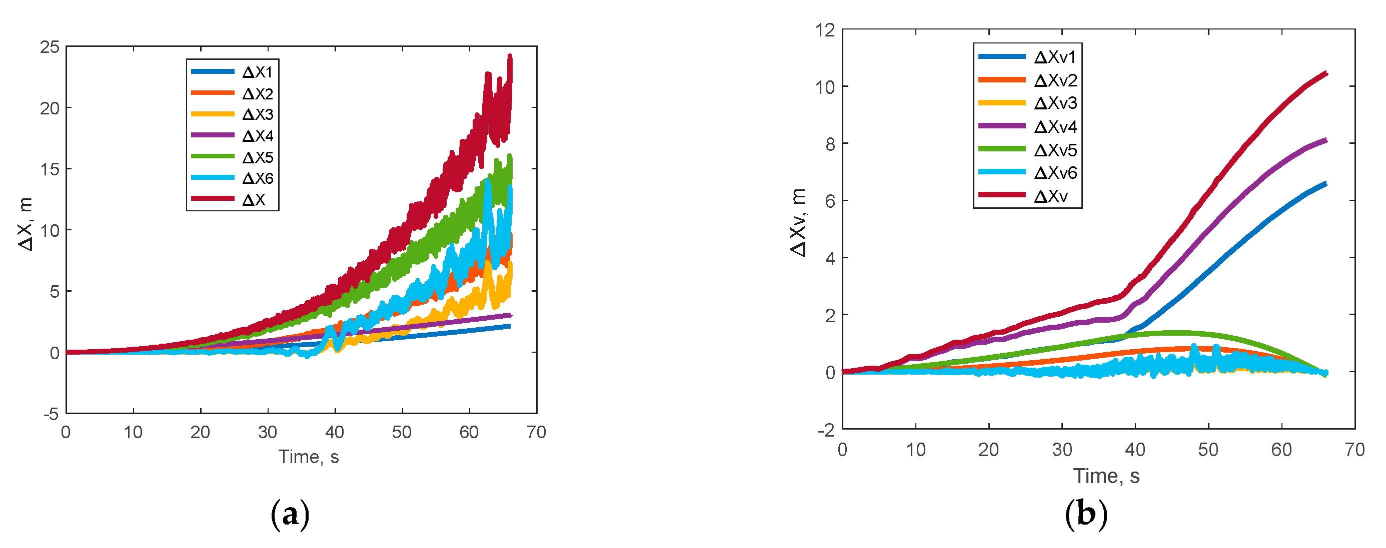
Figure 4.
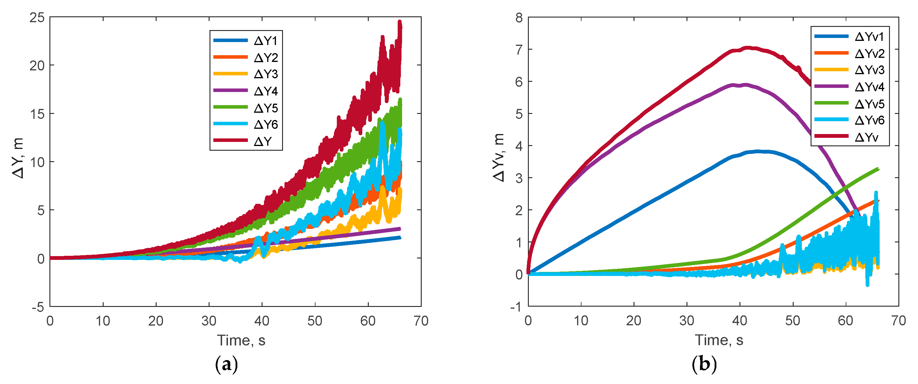
Figure 5.
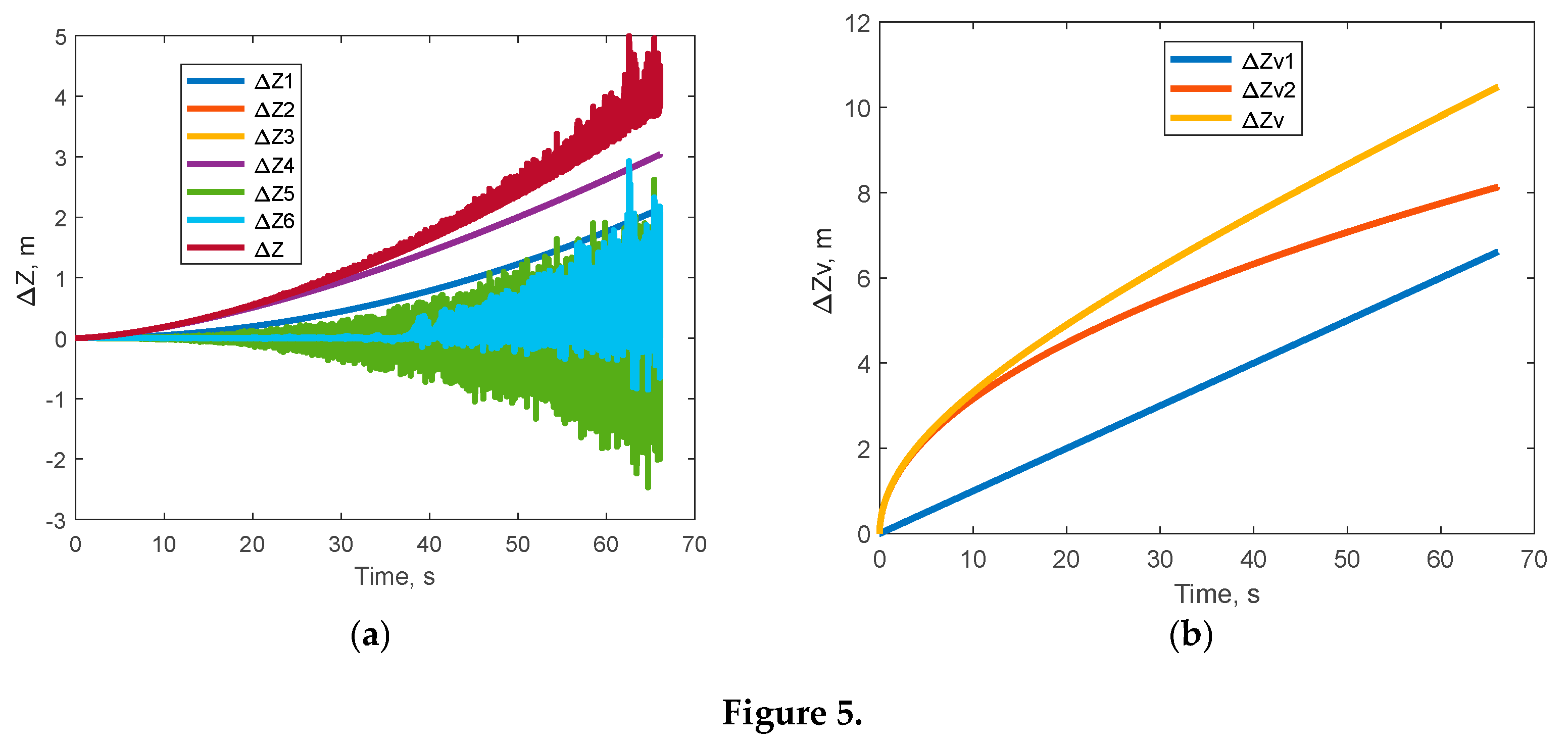
Figure 6.
Values of latitude, longitude and altitude.
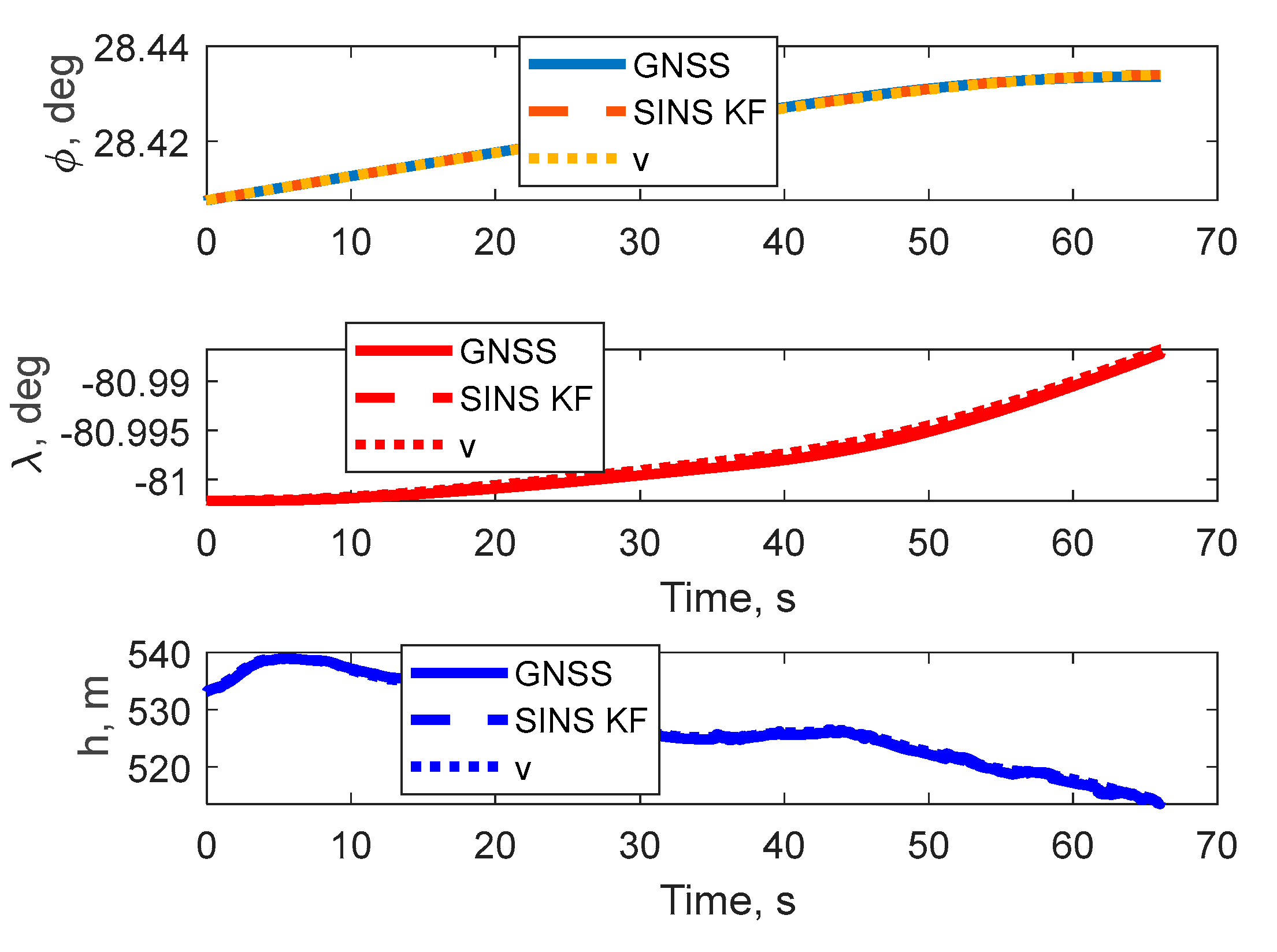
Figure 7.
Errors in determining linear coordinates.
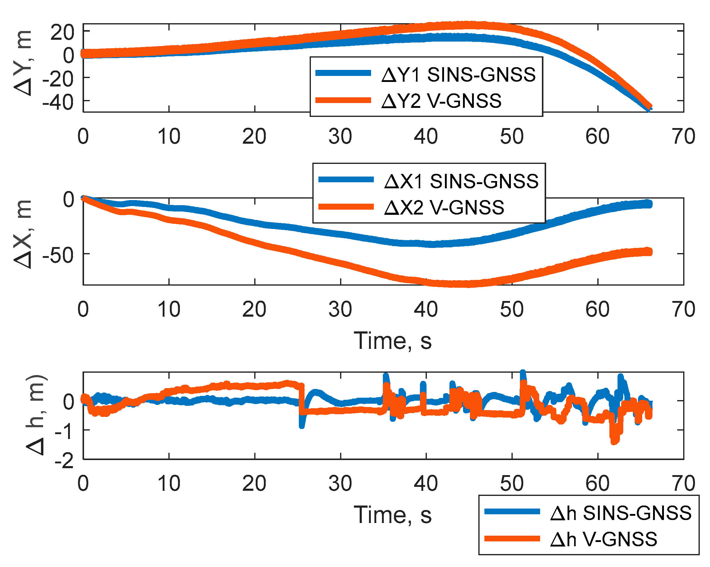
Figure 8.
Values of latitude, longitude and altitude.
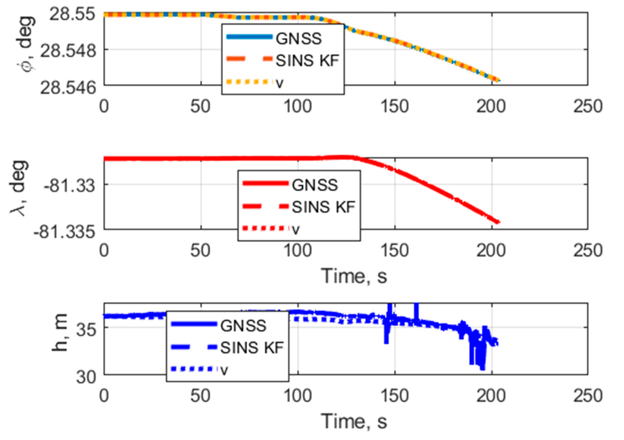
Figure 9.
Errors in determining the altitude and values of latitude and longitude.
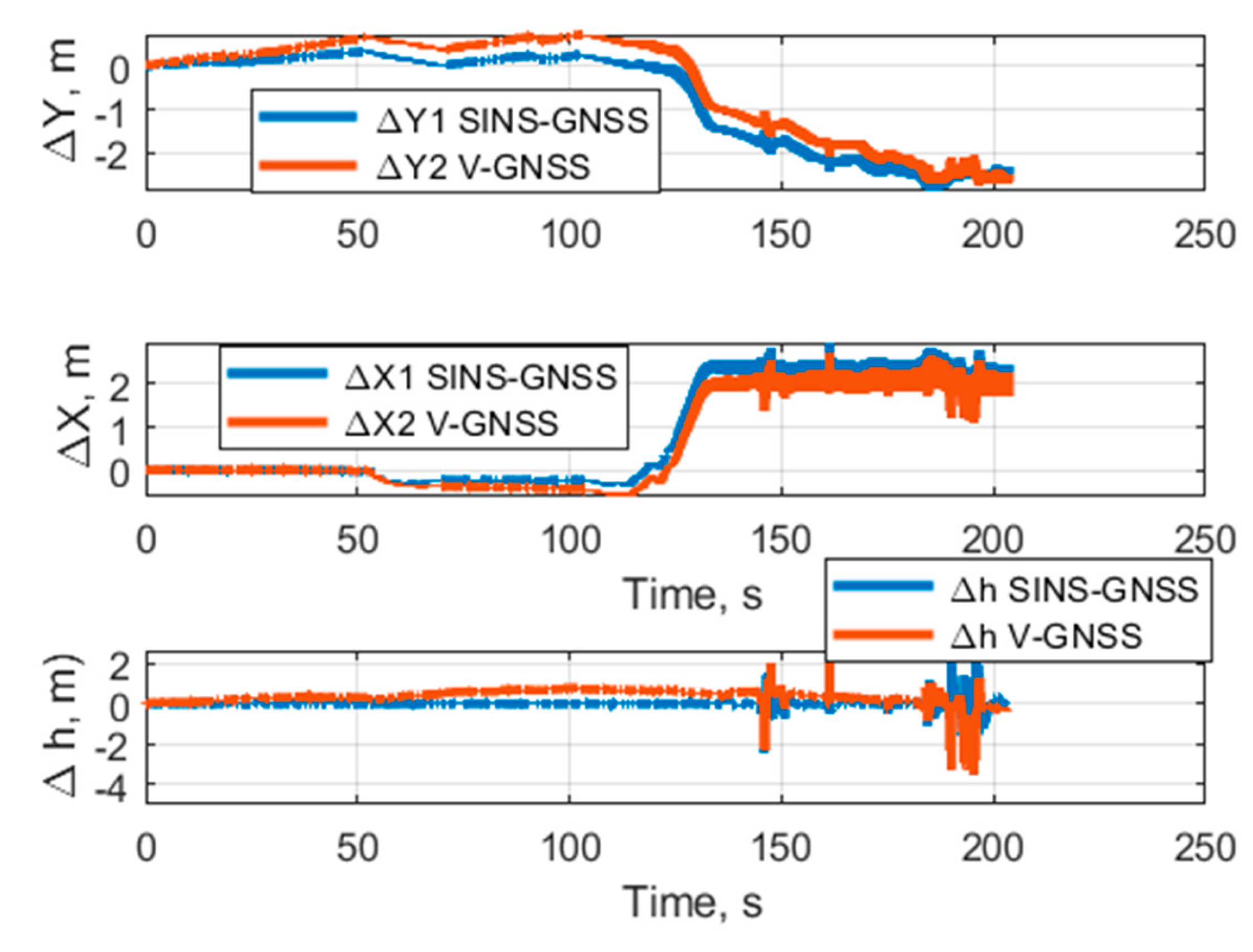
Figure 10.
Values of latitude and longitude, altitude.
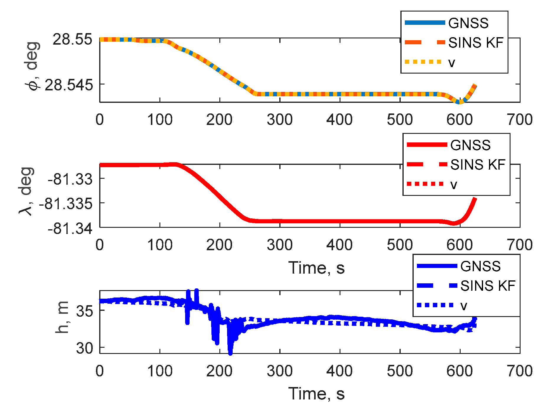
Figure 11.
Errors in determining the altitude and angles of latitude and longitude.

| Errors description | Value |
| Systematic bias of accelerometers, g |
1·10−4 |
| Velocity Random Walk (VRW), m/s2/ | 8·10−3 |
| Systematic bias of gyroscopes, deg/s |
2·10−3 |
| Angular Random Walk (ARW), deg/s/ | 2·10−2 |
| Systematic bias of the velocity sensor, m/s | 0,1 |
| Position Random Walk (PRW), m/s/ | 1,0 |
Disclaimer/Publisher’s Note: The statements, opinions and data contained in all publications are solely those of the individual author(s) and contributor(s) and not of MDPI and/or the editor(s). MDPI and/or the editor(s) disclaim responsibility for any injury to people or property resulting from any ideas, methods, instructions or products referred to in the content. |
© 2026 by the authors. Licensee MDPI, Basel, Switzerland. This article is an open access article distributed under the terms and conditions of the Creative Commons Attribution (CC BY) license (http://creativecommons.org/licenses/by/4.0/).
Copyright: This open access article is published under a Creative Commons CC BY 4.0 license, which permit the free download, distribution, and reuse, provided that the author and preprint are cited in any reuse.


