Preprint
Article

This version is not peer-reviewed.

Engineering Bio-Based Controlled Release Polyphenol Products for Applications in Sustainable Agriculture

Submitted:

10 February 2026

Posted:

12 February 2026

You are already at the latest version

Abstract

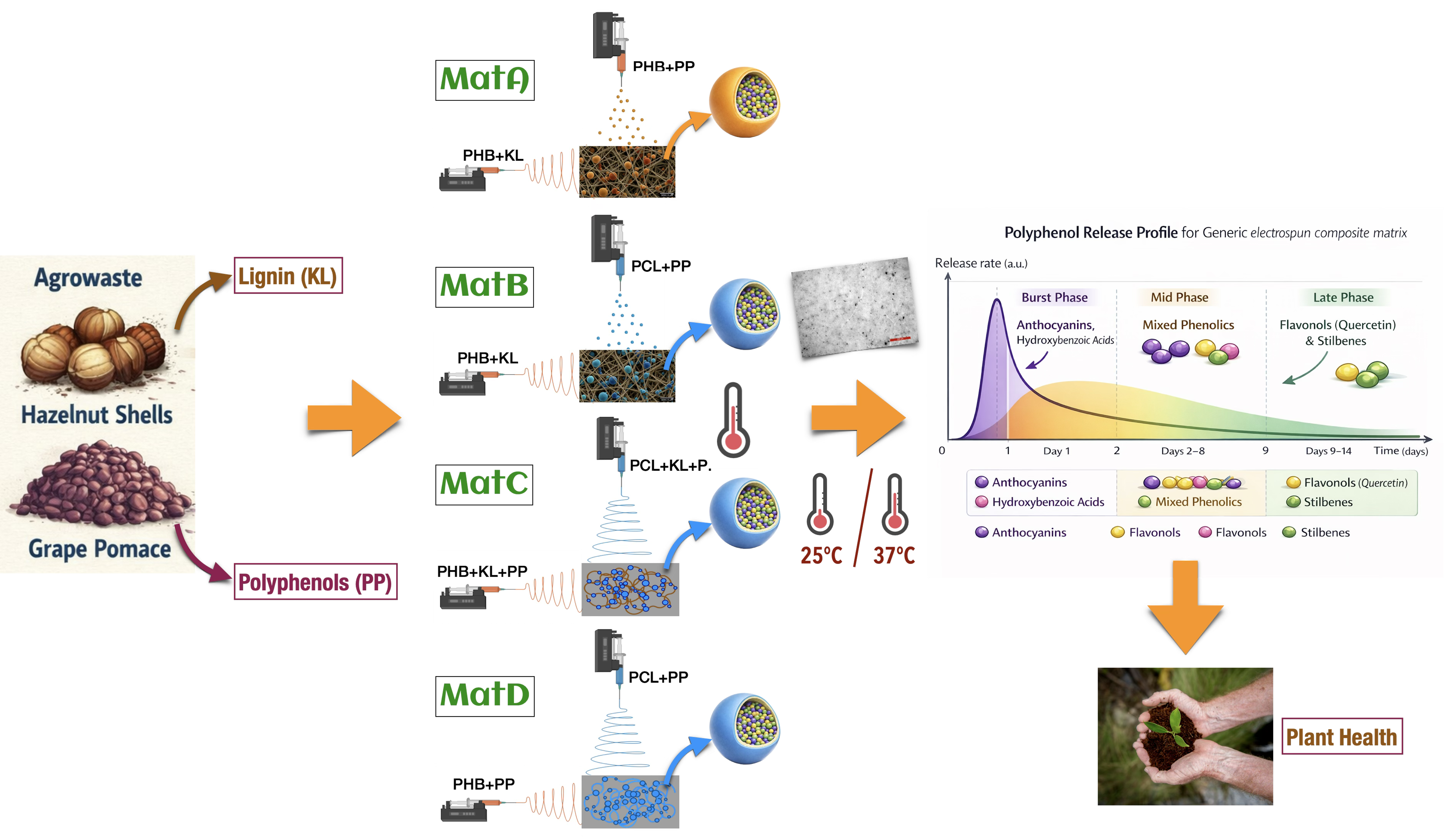
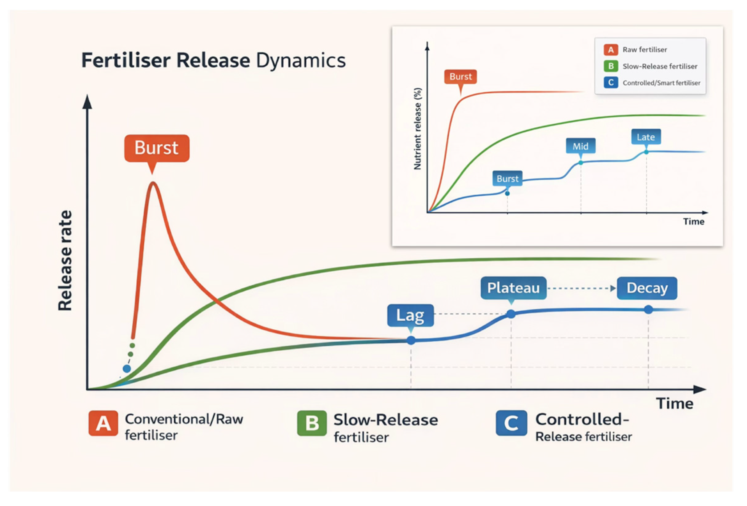
Electrospinning and electrospraying nanotechnologies were used to valorise agro-industrial residues into biohybrid controlled-release polyphenol (CRP) scaffolds. Four polyhydroxybutyrate ± polycaprolactone (PHB±PCL) architectures were fabricated that differed in polymer phase, Klason lignin from hazelnut-shell (HS-KL) presence vs absence and co-location with grape-pomace polyphenols (GP-PP), as well as distribution between fibres and bead-like depots. Scaffolds were characterised using optical microscopy/stereomicroscopy/SEM, FTIR, UV/VIS spectroscopy and dynamic water contact angle (absorption). GP-PP release was monitored for 14 days at ~25 °C and 37 °C, the latter representing shallow-soil hot-spell conditions in Mediterranean zones. All matrices exhibited multimodal release, with modest initial bursts and three phases (burst, mid, and late tail), analogous to controlled-release fertiliser profiles. At ~25 °C, the PHB/PCL matrix with HS-KL confined to PHB fibres and GP-PP in large PCL beads showed the highest total GP-PP release, whereas the architecture with HS-KL and GP-PP co-located in both PHB and PCL fibres and in PCL depots combined high total release with a smoother, well-metered late phase. At 37 °C, this HS-KL-GP-PP co-located scaffold was the most robust, retaining the highest total and late tail release. These results identify HS-KL-GP-PP co-located PHB/PCL architectures as promising carriers for temperature-resilient delivery of bioactive polyphenols in Mediterranean agrosystems.

Keywords: 
;  ;  ;  ;  ;  ;  ;  

1. Introduction

Increasing agricultural productivity is essential to sustain the growing global food demand [1] . This requires both improving crop yields and reducing losses along the production chain [2] . Alongside genetics, agronomy and digital tools, materials science—and in particular nanotechnology—offers additional options to support more efficient and sustainable agricultural systems.

1.1. Nanotechnological Contributions to Agriculture — Electrodeposition Technologies
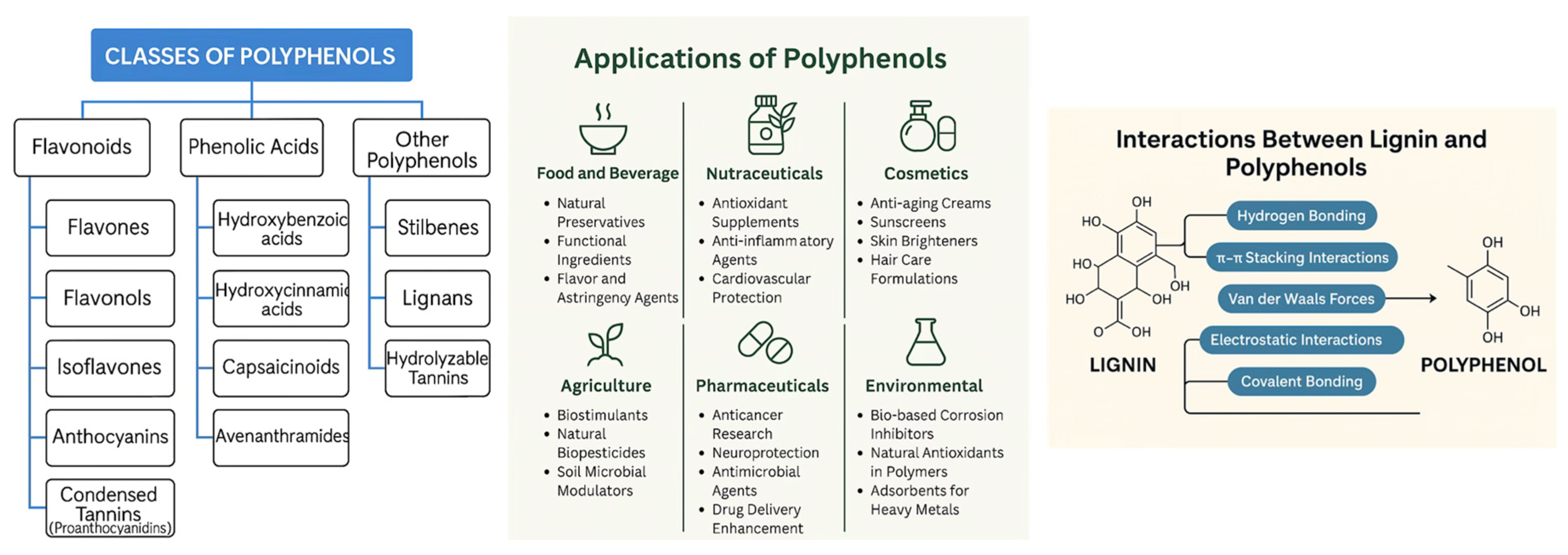
Nanomaterials exhibit size-dependent properties, such as a high surface-area-to-volume ratio, enhanced reactivity, tunable solubility, and distinctive mechanical, electrical, magnetic, optical, and thermal behaviour compared with their bulk analogues [3,4,5,6]. These features have enabled applications in biomedicine, packaging, energy, water treatment, food-related technologies and other sectors (Table S1) [7,8] .
Within this broader field, polymer nanofibres obtained by electrospinning have become a particularly versatile platform [9,10] . Electrospinning is a scalable, relatively low-cost electrodeposition technology that uses electrostatic forces to draw continuous fibres from polymer solutions, suspensions, blends or melts, typically with diameters in the 10 nm–1 µm range [11,12,13] . Nanofibrous structures have been explored in tissue engineering, drug delivery, filtration, antimicrobial materials, energy, environmental remediation, sensors and agriculture (Table S2) [9,10] . Electrospraying, a related process, employs an electric field to generate micro- and nanoscale droplets that solidify into particles under controlled conditions [14,15,16] . Combining electrospinning and electrospraying enables simultaneous deposition of fibres and particles, broadening the range of organic and inorganic components, facilitating the encapsulation of bioactive compounds and generating hybrid mats with tailored architectures and functions [17,18] . In agriculture, nanofibrous systems have been proposed for crop protection, controlled delivery of active substances, and sensing (Table S2).
In parallel, agro-industrial waste is increasingly recognised as a renewable feedstock for producing value-added products [15] . It is typically rich in functional organic matter components, inorganic constituents and bioactive compounds (Table S3). Several products can be recovered from these residues (Table S4). In this work, we focused specifically on lignin and polyphenols extracted from hazelnut shells and grape pomace, respectively, as agro-industrial waste to obtain eco-friendly functional ingredients.

1.2. Lignin

Lignin is the second most abundant natural polymer after cellulose, accounting for roughly 5–35 wt% of plant biomass and 10–52 wt% of agro-industrial residues, depending on species and processing. It is a complex aromatic biopolymer, primarily located in the secondary cell walls of woody and vascular tissues (xylem and bark), built from p-coumaryl, coniferyl, and sinapyl alcohols linked via ether and carbon-carbon (C–C) bonds into a heterogeneous network [19] . Its composition reflects plant genetics, tissue type and environmental conditions.
Owing to its rigid, largely hydrophobic structure, lignin confers mechanical strength, facilitates water transport and enhances resistance to microbial degradation. It also exhibits antioxidant, antifungal, antimicrobial, and UV-protective properties [19,20,21,22]. These characteristics have supported a growing range of applications in the food sector, biorefineries and biofuels, wood adhesives, biomedical materials, coatings, catalysts, surfactants, drug-delivery systems, packaging and other functional materials [21,23,24,25,26,27,28] . In this study, lignin recovered from hazelnut shells was used as a bio-based functional additive in electrospun ± electrosprayed nanofibrous architectures.

1.3. Polyphenols

Polyphenols are among the dominant secondary metabolites in plants and are widely distributed in fruits, vegetables, cereals, tea, coffee and many other crops. More than 10,000 plant polyphenols have been identified [29] . They generally contain one or more hydroxylated aromatic rings and can occur as monomeric phenylpropanoids or as oligomeric and polymeric forms, such as proanthocyanidins [30,31,32] .
Their biosynthesis involves the shikimate and phenylpropanoid pathways, which generate hydroxybenzoic and hydroxycinnamic acids and precursors for a broad range of compound classes. Based on structural features, polyphenols are commonly grouped into flavonoids (e.g., flavones, flavonols, isoflavones, anthocyanins and condensed tannins), phenolic acids (hydroxybenzoic and hydroxycinnamic acids, capsaicinoids, avenanthramides) and other polyphenols (stilbenes, lignans and hydrolysable tannins) (Figure 1A) [29] . The number and position of hydroxyl and methoxy groups, and the presence of hydrophobic substituents (e.g., prenyl groups, alkyl chains), lead to a wide range of polarities, from highly hydrophilic molecules (e.g., gallic acid) to strongly hydrophobic ones (e.g., pterostilbene). Through these functional groups and their aromatic rings, polyphenols engage in hydrogen bonding, electrostatic interactions, hydrophobic interactions and π–π stacking (Figure 1C) [33,34] .
These structural features underpin their antioxidant, antimicrobial, anti-inflammatory, and anticancer activities and explain their use in food and beverages, nutraceuticals, cosmetics, agriculture, pharmaceuticals, and environmental technologies (Figure 1B). When extracted from agro-industrial residues such as grape pomace, polyphenols can be incorporated into value-added materials. Here, polyphenols isolated from grape pomace were incorporated into bio-based nanocarriers (nanofibres and bead-like depots) for agricultural delivery.

1.4. Carriers

To fabricate electrospun nanofabrics capable of encapsulating waste-derived polyphenols for controlled delivery to plants, polyhydroxybutyrate (PHB) and polycaprolactone (PCL) were selected as biodegradable carrier polymers compatible with both electrospinning and electrospraying.
PHB is a partially crystalline polyester that can be obtained synthetically or produced by microorganisms. It is biodegradable and biocompatible and exhibits thermoplastic properties comparable to those of conventional polyolefins such as polyethylene and polypropylene [35,36,37] . PHB has been proposed for biodegradable packaging, agricultural films, medical devices, and disposable items, thereby contributing to reduced plastic waste and circular-economy strategies [38,39,40].
PCL is a semi-crystalline, hydrophobic polyester with good mechanical strength and slow degradation [41,42]. Its properties and degradation behaviour can be tuned by incorporating natural fillers and additives, such as starch, cellulose, chitosan, lignin, gelatin or silk [43], thereby supporting its use in tissue engineering and controlled-release systems [41]. In this work, PHB and PCL were used alone or in combination as carriers for lignin and polyphenols in electrospun ± electrosprayed scaffolds.

1.5. Aims

This study integrates environmentally friendly components, i.e. PHB and PCL, lignin from hazelnut shells and polyphenols from grape pomace, into electrospun ± electrosprayed biohybrid architectures designed as polyphenol-delivery systems for agricultural applications. The extracted substances and the resulting nanostructured fabrics were characterised to identify the physicochemical determinants of polyphenol release, with particular attention to the role of lignin content and distribution within the scaffolds.
Polyphenol release was evaluated at ambient temperature (~25 °C) (TA) and at 37 °C (T37) over 14-day soaking in 0.11 M phosphate buffer (pH 7.4) (§2.7). Ambient conditions reflect typical soil application scenarios, whereas T37 was used as a stress temperature to probe the thermal robustness of the architectures. Such temperatures can occur at shallow soil depths (0–5 cm, occasionally 10 cm) in Mediterranean and other warm regions during hot periods, particularly in dry or sparsely vegetated soils, on dark or tilled surfaces, in plastic-mulched fields, on south-facing slopes or on recently burned sites.

2. Materials and Methods

2.1. Materials

Poly[(R)-3-hydroxybutyric acid] (PHB, natural origin), polycaprolactone (PCL, Mn = 45,000 g/mol), acetic acid (≥99%), absolute ethanol (analytical grade), 2,2,2-trifluoroethanol (TFE), phosphate buffer (pH 7.4), methanol, ammonium dihydrogen phosphate, orthophosphoric acid, acetonitrile and phenolic standards (≥98% purity) were purchased from Sigma-Aldrich (Merck KGaA, Darmstadt, Germany). Syringe filters (0.22 μm, 33 mm) were from Sigma-Aldrich (Italy).
Hazelnuts (Corylus avellana L.) were purchased from a supermarket in Southern Italy. Nuts were cracked with a nutcracker; the outer shells (HS) were collected, milled to a powder using a stainless-steel blade mill, passed through a 250 μm sieve, aliquoted and stored at -20 °C in hermetically sealed, polyethylene bags before further analysis.
Grapes (Primitivo di Gioia del Colle, Azienda Agricola F.lli Rossi Soc. Agr. srl – Centovignali, Bari) were harvested at 24 °Brix, destemmed and crushed. The must was supplemented, per 100 kg of grapes, with 4 g of potassium metabisulfite (K₂S₂O₅), 30 g of dry yeast (Zymaflore FX10, Laffort, France), and 20 g of diammonium phosphate [(NH₄)₂HPO₄] (D&C Wine, Italy). Alcoholic fermentation was conducted at 22 °C for 15 days with two daily manual punch-downs. At the end of fermentation, pomace was separated and pressed (Torchietto “Premi Tutto” ALU20 Medio, Polsinelli, Italy) and stored at 4 °C until extraction.

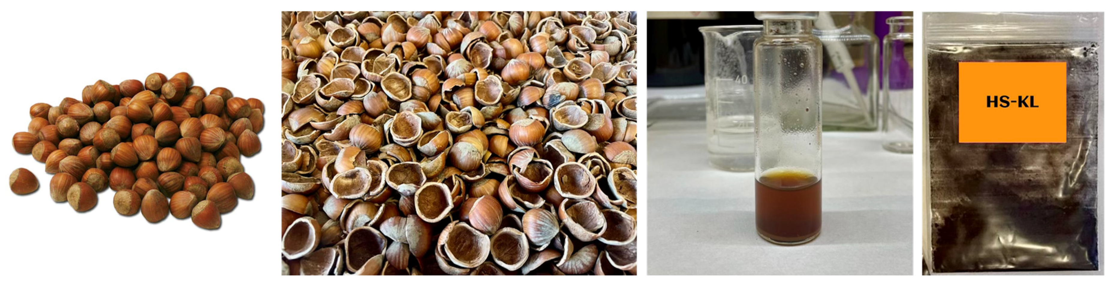
2.1.1. Lignin Extraction

Lignin was obtained as acid-insoluble lignin by the Klason method from hazelnut shell powder, according to TAPPI T 222 om-02 [44] , with minor modifications (hereafter HS-KL) [39]. Briefly, 5 g of HS powder were treated with 150 mL of 72% (v/v) H₂SO₄ (solid-to-liquid ratio 1:30 w/v) at room temperature for 16 h. The mixture was diluted to 3% (v/v) with deionised water and heated at 105 °C under stirring (300 rpm) for 4 h. The suspension was vacuum-filtered on Whatman N°2 paper to collect the acid-insoluble lignin (hereafter HS-KL, Hazelnut-shell Klason lignin), which was repeatedly washed with distilled water (≥10 x 10-min washing cycles) until neutral pH was reached, then dried under vacuum at 80°C (IKA HB 10 basic rotary evaporator, IKA Italy) and stored at 7 °C in dry conditions [45] . Extraction yield was calculated gravimetrically on a dry-weight basis relative to the mass of the initial HS powder (Figure 2).

2.1.2. Polyphenol Extraction

Grape pomace was frozen in liquid nitrogen and ground using an IKA analytical batch mill (IKA-Werke GmbH & Co. KG, Staufen, Germany). Four grams of powder were extracted with 40 mL of methanol:water (80:20 v/v) in a low-temperature ultrasonic bath for 20 min. Samples were centrifuged at 11,200 × g for 15 min at 4 °C, and the supernatant was used for polyphenol analysis.
The grape-pomace polyphenols (GP-PP) present in the extract were identified and quantified by HPLC, following the method of Ritchey and Waterhouse (1999) [46]. A 10 mL aliquot was filtered through 33 mm-diameter 0.22 μm syringe filters (Sigma-Aldrich, Italy), diluted 1:20 (v/v) with Milli-Q water, and 1 mL was transferred to 2 mL amber vials. Analyses were performed using a Dionex HPLC system (P680 pump, manual injector with 20 μL loop, TCC-100 oven, PDA-100 detector, Chromeleon v.6.50). Separation was carried out on a C18 column (Dionex Acclaim® 120 C18, 5 μm, 4.6 × 250 mm).
The mobile phase consisted of: solvent A, 50 mM ammonium dihydrogen phosphate (pH 2.8, orthophosphoric acid); solvent B, 20% A/80% acetonitrile; solvent C, 0.2 M orthophosphoric acid (pH 1.5, NaOH). Flow rate was 0.5 mL/min at 40 °C. Quantification was based on a 5-point calibration (0.1–200 mg/L) using phenolic standards.

2.2. Electrospinning and Electrospraying Solutions

Nanostructured frameworks were prepared by combining biodegradable polymers (PHB, PCL) with lignin and polyphenols extracted from agro-industrial waste.
PHB and PCL stock solutions were prepared by dissolving PHB (228 mg mL⁻¹) and PCL (266.67 mg mL⁻¹) in 2,2,2-trifluoroethanol (TFE). TFE was selected because it dissolves both polymers and promotes bead formation during PCL electrospinning, thereby enabling fibre-and-bead architectures.
Hazelnut-shell Klason lignin (HS-KL) was dissolved in acetic acid (80 mg mL⁻¹). Polyphenols from grape pomace (GP-PP) were diluted in methanol:water (80:20 v/v) to 100 mg mL⁻¹. Seven formulations were prepared by mixing PHB, PCL, HS-KL and GP-PP in different ratios (Table 1). For each formulation, the electrospinning ± electrospraying process was continued until the syringe contents were fully discharged.
All solutions were sonicated using a probe sonicator (6000 J mL⁻¹, Vibra Cell VCX 400, Sonics and Materials Inc., Newtown, USA), vortexed and magnetically stirred at room temperature until complete homogenisation.

2.3. Electrospinning/Electrospraying of Nanostructured Frameworks

Four nanostructured fibrous fabrics were produced by combining the seven formulations in different ways and, in selected cases, coupling electrospinning and electrospraying in a Fluidnatek® LE-50 system (Bioinicia, Paterna, Valencia, Spain), under the conditions reported in Table 1. Table 1 also summarises the mass ratios of the various components in each final scaffold.

2.4. Morphological Characterisation

2.4.1. Stereomicroscopy and Optical Microscopy

Scaffold fragments were mounted on thin SiO₂ wafers. Stereomicroscopy was performed with an Ivesta 3 Greenough stereo microscope with integrated camera (Leica Microsystems GmbH, Wetzlar, Germany). Optical microscopy was performed using a DM2700 M microscope equipped with a K5C Colour CMOS camera (Leica Microsystems GmbH, Wetzlar, Germany). These observations provided an overview of the surface texture, fibre network, and the presence of dark particles before and after 14-day soaking in 0.11 M phosphate buffer (pH 7.4) at 37 °C.

2.4.2. Scanning Electron Microscopy and Image Analysis

Morphology was further analysed by field-emission scanning electron microscopy (FE-SEM) using a Tescan MAGNA GMU (Tescan, Czechia) equipped with an AztecLive EDS system with Ultim Max 65 detector (Oxford Instruments, UK). Samples were electrospun directly onto silicon wafers with native SiO₂, mounted on aluminium stubs with conductive carbon tabs and sputter-coated with ~5 nm Au.
SEM micrographs were acquired in secondary-electron mode at magnifications of 2k×, 5k×, 10k×, 15k× and 20k×, with accelerating voltages between 2 and 20 kV, beam current of 30 pA and field-of-view between ~17 and 70 μm. Several images per sample were collected to assess homogeneity and capture key features (fibre diameter, bead formation, surface roughness, globular/embedded structures).
Average PHB and PCL fibre diameters were measured on comparable micrographs using the DiameterJ v.1-018 plugin in ImageJ (≥102 measurements per scaffold from three different pieces). For matrices where unexpected PCL nanofibres formed during intended electrospraying, these were excluded from fibre-diameter statistics, as the design rationale was to compare planned morphologies and their effect on lignin/polyphenol behaviour.
Particle area and roundness were measured on PHB and PCL particles generated by electrospraying (PHB and PCL) or electrospinning (PCL), based on SEM images analysed with ImageJ 1.51k (≥51 measurements per scaffold from three pieces). Roundness, as calculated by the software, is a dimensionless shape descriptor that quantifies how closely a particle resembles an ideal circle. Values approaching 1 correspond to nearly spherical particles, whereas progressively lower values indicate increasingly elongated, irregular, or deformed shapes. This parameter was employed to monitor potential morphology changes, such as deformation or surface erosion, before and after 14-day soaking in 0.11 M phosphate buffer (pH 7.4), regardless of particle size or origin (electrosprayed vs. electrospun).

2.5. Interactions of the Nanohybrid Scaffolds with Water

2.5.1. Water Contact Angle (WCA) Measurements

Dynamic WCA were measured with a custom-built setup equipped with a Supereyes B011 5 MP digital USB microscope. A 7 μL droplet of distilled water was deposited on the scaffold surface using a calibrated micropipette. Droplet profiles were recorded at 0, 30, 60, 90, 120, 180, 240, 300, 450, and 600 s. Contact angles (θ) and droplet volumes were obtained by drop-shape analysis (axisymmetric drop shape analysis, ADSA) using the Drop Analysis LB_ADSA plugin in ImageJ.

2.5.2. Water Absorption/Infiltration

Water uptake was expressed as the percentage change in water droplet volume (WDV) over time relative to the initial 7 μL (100%). Volumes at each time point were extracted from the same image series used for WCA by ADSA analysis, enabling assessment of evaporation versus absorption/infiltration into the porous scaffolds.

2.6. Spectroscopic Characterisation

2.6.1. UV–VIS Spectroscopy

UV–VIS spectra of HS-KL and GP-PP solutions were acquired between 185 and 700 nm using a UV-2600 spectrophotometer (Shimadzu, Kyoto, Japan). Polyphenols were measured in methanol:water (80:20 v/v) extracts (1 mg mL⁻¹), which were subsequently dissolved in 0.11 M phosphate buffer (pH 7.4) at 37 °C to maximise solubility. HS-KL was dispersed in phosphate buffer and analysed by UV–VIS spectroscopy under the same conditions.
UV–VIS spectroscopy was also used to monitor GP-PP release by measuring the absorbance of phosphate buffer solutions in which the scaffolds were soaked for 14 days at either ~25 °C or 37 °C (§2.7).

2.6.2. Fourier Transform Infrared Spectroscopy (FTIR-ATR)

Fourier-transform infrared (FTIR) spectra of lignin were recorded using a Spectrum 3 Tri-Range MIR/NIR/FIR spectrometer (PerkinElmer, Waltham, MA, USA) equipped with a Universal ATR diamond crystal. Spectra were collected in the 4000–650 cm⁻¹ range at 4 cm⁻¹ resolution, with 16 scans per sample at room temperature. Characteristic lignin bands were used to confirm the presence of typical functional groups in the extracted Klason lignin.

2.7. Polyphenol Release from the Nanostructured Scaffolds

Grape-pomace polyphenol (GP-PP) release was assessed by UV–VIS analysis of buffer solutions in which the nanostructured fabrics were immersed. Diffusion-driven release is temperature-dependent through the diffusion coefficient and polymer mobility; therefore, experiments were performed at two temperatures: ambient (~25 °C, TA) and 37 °C (T37), which was used as the stress temperature.
Scaffold strips (1 cm × 5 cm; 5 cm²) were immersed in 5 mL of 0.11 M phosphate buffer (pH 7.4). For each scaffold and temperature, the incubation medium was collected in full at each sampling time (daily over 366 h -14 days, with an additional sampling point at 6 h on day 1). An aliquot of the collected solution was used for UV–VIS analysis, and the scaffold was subsequently incubated in fresh buffer (5 mL) for the next time interval.
The 0.11 M phosphate buffer (pH 7.4) was chosen to provide a stable aqueous medium with a pH representative of Mediterranean agricultural soils, which typically range from slightly acidic to moderately alkaline with mean values around 7.4 (4.3–8.6) [47,48] . This avoided pH-driven artefacts in polyphenol spectra and ensured comparability across matrices.
UV–VIS spectra of the release media exhibited two main polyphenol-related peaks (λ1 ≈ 208 nm and λ2 ≈ 280 nm) and a shoulder around 320–330 nm (§3.1.4). Peak areas were integrated using the instrument’s software. For quantitative analysis, the shoulder contribution was merged with the λ2 peak. Polyphenol release was expressed as arbitrary units.
For each scaffold and time point, the total polyphenol-related area (Atotal) was defined as:
Atotal = A1 + A2,
where A₁ is the integrated area at λ₁ (≈208 nm), and A₂ is the integrated area at λ₂ plus shoulder (≈280-330 nm). These areas reflected the combined contributions of multiple polyphenolic species in the extract and thus represented the overall polyphenol content rather than those of individual compounds (Supplementary Materials, §S4).
Normalised polyphenol release (PPnorm) was then calculated as:
P P n o r m t = A t o t a l ( t ) m P P ,
where mPP is the estimated theoretical mass of GG-PP loaded in the tested strip (based on initial formulation). This normalisation allowed comparison across scaffolds with different initial GP-PP loadings. Based on the GP-PP release measurements obtained from the procedure above, the GP-PP release profile over time performed at TA and T37 was quantified, and various phases were identified by analogy with controlled-release fertiliser (CRF) descriptors: burst, mid, late tail, total released area, late fraction, and t50. Specifically, the burst = the period including the first peak; mid = includes the second peak; late tail = includes the third peak plus the terminal shoulder, if present; total = the total released polyphenols over the entire period of measurements; late fraction = late tail area/total area, i.e. the proportion of the total that occurs in that same late window; t50 = time at which the cumulative release area reaches 50% (linear interpolation between the timepoints). Because release profiles were multimodal, phase areas were quantified primarily by a peak-centred approach. Peak domains were then delimited by inter-peak minima, yielding burst (first peak), mid (second peak), and late tail (third peak + terminal shoulder) contributions. A fixed-window integration was used only as a secondary sensitivity analysis for cross-condition comparability among the matrices and the temperatures tested: burst (0–78 h), mid (78–192 h), and late tail (>192 h).

2.7.1. Daily Release Normalisation and Comparison

To compare scaffolds on a daily basis within the same matrix type, the daily polyphenol release of each scaffold was first normalised to the total amount of polyphenols released over the entire experimental period (14 days) by that specific matrix, which was set to 100%. The relative daily contribution of each scaffold i was then calculated as a percentage of the matrix's total daily release.
P P r r e l e a s e / d a y ( i ) % = A i ( d a y ) j = 1 n A j ( d a y ) ,
where A i ( d a y ) is the daily released polyphenol signal (e.g. UV–VIS area) of scaffold i, expressed as a fraction of the total amount released over 14 days by the same matrix (100%), and the denominator is the sum of the daily released fractions over all n scaffolds belonging to that matrix. This normalisation enabled a scaffold-by-scaffold comparison within each matrix type, independent of differences in absolute release among the four matrix formulations.

2.7.2. Polyphenol Release Rate Trend Analysis

Cumulative normalised release curves were obtained by summing PPnorm over time for each scaffold. To provide a first-order approximation of release kinetics and facilitate comparison, linear regressions were fitted to the cumulative data as:
y = ax+b,
where y is the cumulative normalised release (sum of peak areas divided by mPP), x is time (h), a is the apparent release rate (area units·h⁻¹), and b is the intercept. The coefficient of determination (R2) (OriginPro, OriginLab) was used to assess goodness of fit over the whole 14-day period (~340 h) and to compare overall release trends across scaffolds and temperatures.

3. Results and Discussion

In this study, we intended to develop environmentally friendly products for applications in sustainable agriculture. To achieve this goal, we employed various low-impact components from different sources. In typical drug delivery systems that act on organisms, a carrier architecture encases bioactive substances that must be released outward to perform their functions. In detail, we utilised polyhydroxybutyrate (PHB) and polycaprolactone (PCL) as biodegradable carrier polymers to create various architectures using electrospinning ± electrospraying as nanotechnological techniques. Then, we extracted lignin and polyphenols from agro-industrial waste as valuable compounds to engineer bio-based, controlled-release polyphenol products that support plant growth.

3.1. Extraction and Characterisation of Valuable Bio-Based Compounds from Agro-Industrial Waste

3.1.1. Valuable Compounds from Agro-Industrial Waste for Functional Agricultural Purposes

Within the EU bioeconomy framework, agricultural residues are regarded as a resource rather than waste, provided they are channelled into value-added uses through a cascading scheme [49,50] . In this view, the extraction of high-value molecules and materials from agro-industrial streams should precede low-value options such as direct combustion. This approach is not marginal: agro-industries generate on the order of 1.3–2.1 billion tonnes of residues per year worldwide [51] , and these materials are typically rich in lignocellulosic biomass (cellulose, hemicellulose, lignin), proteins, minerals and a broad array of secondary metabolites [52,53] . Agro-industrial waste has been already exploited to recover biopolymers, biofuels, enzymes, and nutraceuticals as valuable materials, and, more recently, as precursors for bio-based nanomaterials and nanocomposites (Tables S3–S4).

3.1.2. Lignin Extraction

Hazelnut-shell Klason lignin (acid-insoluble fraction) (HS-KL) was extracted from milled hazelnut shell powder according to the two-step acid hydrolysis protocol described in §2.1.1. The procedure was readily implemented under laboratory conditions and yielded reproducible results. On a dry-weight basis, the extracted HS-KL was ~48.9 wt% of the starting hazelnut shell material, confirming that this residue was lignin-rich and suitable as a feedstock for lignin recovery within a circular bioeconomy context. Figure 3B shows the UV/VIS absorbance spectrum of the extracted HS-KL.
Lignin is a key component of agro-industrial waste. In addition to its historic roles in pulping and energy, it has been introduced into a wide range of applications, including packaging, biorefinery intermediates, wood adhesives, biomedical formulations, coatings, catalysts, and drug-delivery systems [21,23,24,25,26,27,28] . The development of “nanolignin” has further expanded this portfolio: nanosized lignin often disperses more effectively, interacts more efficiently with polymer matrices, and can enhance mechanical, thermal, and barrier properties [22,54] . Electrospun lignin-containing fibres and nanocomposites have been proposed for drug delivery, filtration, energy devices and biomedical uses [55,56,57,58] , confirming that lignin can act both as a structural modifier and as a carrier or co-carrier for active substances [27,54,55,59,60] .
We employed Klason lignin from hazelnut shells as a reinforcing and potentially release-modulating co-component, either embedded or co-deposited with polyphenols in nanocomposite PHB ± PCL architectures, to modulate mechanical stability and hydration and ultimately generate polyphenol-loaded fabrics with controlled-release properties.

3.1.3. Polyphenol Extraction

Polyphenols were extracted from grape pomace (GP-PP) following the method reported in §2.1.2. HPLC–PDA analysis of the extract revealed five main polyphenol classes, including anthocyanins, flavan-3-ols, flavonols, phenolic acids, and stilbenes (Table 2), (Figure S1).
Polyphenols form the second major group of value-added molecules that can be recovered from agro-industrial residues. Their biomedical effects are well known, but in the present context, their native roles in plants and soils are more relevant. In plants, polyphenols contribute to defence against herbivores and pathogens through antimicrobial, antifungal and deterrent activities, and they support tolerance to abiotic stresses such as drought, salinity, excess radiation and temperature extremes by scavenging reactive oxygen species and helping to preserve membrane integrity and DNA structure [29,61,62,63] . In soil–plant systems, they also influence nutrient cycles: they chelate micronutrients such as Fe, with consequences for P and other elements, retain Ca, Mg and K on exchange sites, and slow litter and SOM turnover via protein complexation and direct inhibition of microbial growth or enzyme activities [63,64,65] . In addition, many polyphenols act as signals, mediating allelopathic interactions, legume–rhizobia recognition and the stimulation or suppression of fungal germination and hyphal growth [62,63,66] . Anthocyanins and related flavonoids also contribute significantly to plant pigmentation and aroma, thereby influencing pollination and seed dispersal [61,62,67] . Through adsorption onto clays and oxides, polyphenols ultimately form organo–mineral complexes and contribute to the stabilised fraction of soil organic matter [64,68] .
These ecological roles have clear analogues in engineered systems. Plant-derived polyphenols are used as green reducing and stabilising agents for metal and metal-oxide nanoparticles, as antioxidants and UV stabilisers in polymer nanocomposites, as antimicrobial and structuring components in biopolymer films, as building blocks for lignin- or tannin-based hydrogels, foams and coatings, and as functional interlayers in stratified nanostructures [69,70,71,72] . In all these cases, polyphenols combine technical functionality with a low-impact feedstock. In this study, a grape-pomace polyphenol extract was used as the bioactive cargo to support plant health. To achieve this goal, polyphenols were dispersed either within the fibres and/or in bead-like depots comprising the scaffolds. Polyphenols were combined with carrier polymers and lignin to tailor the architecture and, consequently, the polyphenol release behaviour.
Based on class and structure, the overall extract is predominantly hydrophilic, with only a minor contribution from more hydrophobic species (Table S5). This polarity profile is relevant to both interactions with PHB and PCL during electrodeposition and to the subsequent release behaviour in aqueous buffer.

3.1.4. Valuable Spectroscopic Characterisation of the Extracted Substances

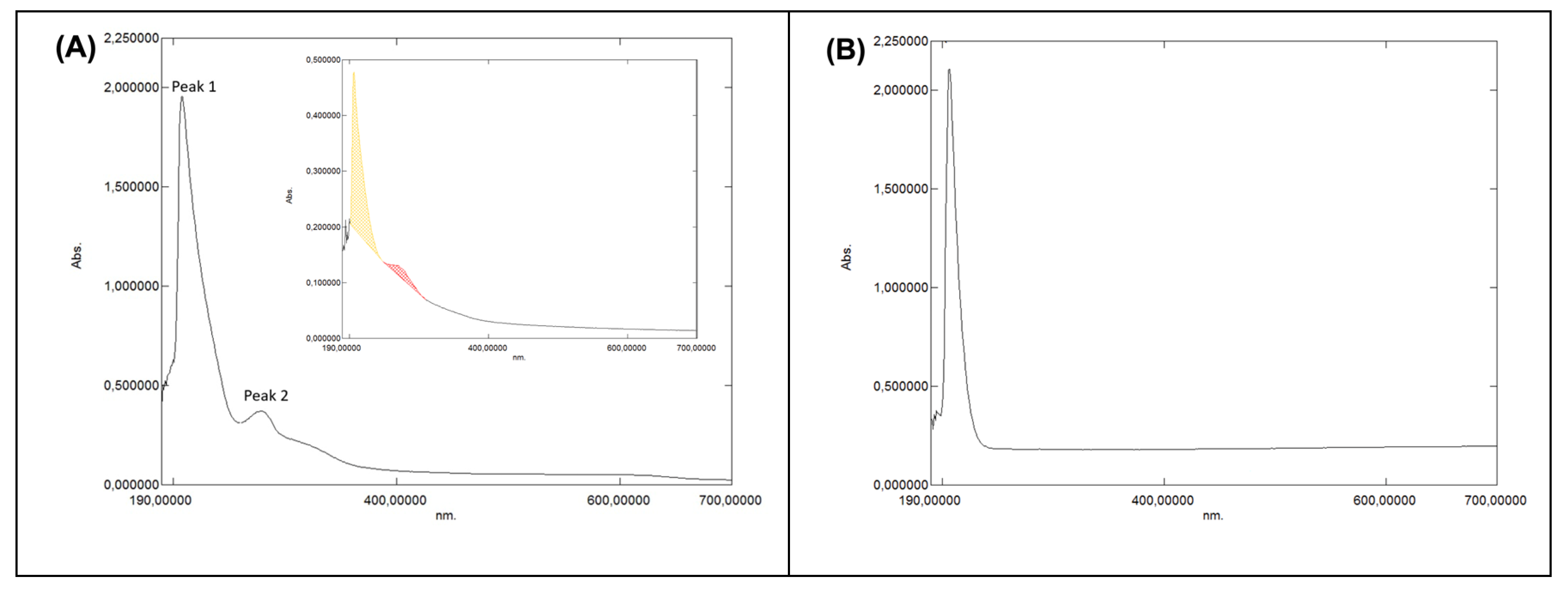
3.1.4.1. UV–VIS Characterisation of the Grape-Pomace Extract

The UV–VIS spectrum of the methanol:water (80:20, v/v) grape-pomace extract displayed two main absorption regions (Figure 3A): a strong band at ~208 nm (Peak 1) and a second band at ~280 nm (Peak 2) with a shoulder around 320–380 nm (Figure 3A). The first peak is characteristic of intense and high-energy far-UV π–π* transitions in aromatic rings (“E/B” band), while the second band is consistent with lower-energy π–π* transitions (Band II), often described as “benzenoid/benzoyl system” transitions in flavonoids and due to hydroxyl and carbonyl groups within aromatic structures typical of phenolic acids (like gallic acid) and flavan-3-ols. Moreover, the slight 320-380 nm shoulder is typical of π–π* transitions (Band I) in flavonols and flavones. Typically, plant extracts are composed of a multitude of different polyphenols (flavonoids, phenolic acids, stilbenes, hydrolysable tannins, lignans, etc.) (Figures S2 and S3D). In addition, solvents used for the UV/VIS measurements and pH further modulate peak position and intensity in UV/VIS absorbance spectra (§S4): acidic polyphenols dissolved in 0.11 M phosphate buffer (pH 7.4) at ~25 °C exhibit reduced absorbance and slightly shifted maxima relative to more acidic conditions, consistent with reported bathochromic and hypochromic trends [31,73,74,75,76,77,78,79,80,81] (Figure S3A,B).
Furthermore, plant extracts contain not only several polyphenol classes but also other cell-derived solutes. Hence, the resulting UV/VIS absorbance spectra will represent the superposition of multiple plots. A simple spectral reconstruction is reported in S3, combining typical spectra of free polyphenols, proanthocyanidins, tannin–protein complexes, and minor soluble proteins, and reproducing the main features of the measured spectrum (Figure S3C). The intense 208 nm peak can therefore be interpreted as arising from overlapping contributions of free and protein-bound polyphenols and condensed tannins and is typically much higher than the others [82] , whereas the 280 nm band is mainly associated with phenolic acids/flavan-3-ols, tannic acid, anthocyanins and proanthocyanidins [76,77,83] (Figure S3C).
Direct HPLC–PDA detection at 280 nm confirmed the presence of gallic acid, procyanidin dimers, (+)-catechin and 4-hydroxybenzoic acid, additional to other polyphenol compounds (Table 2, Figure S1), which is consistent with both the simulated composite UV/VIS spectrum (Figure S3C) and the wine and pomace phenolic profiles (Figure S3D).3.1.4.2. UV-VIS characterisation of Klason lignin from hazelnut shells
The UV-VIS spectrum of HS-KL exhibited a strong absorption band at ~207 nm, with a much weaker, broader feature centred at ~480 nm (Figure 3B). The deep-UV band reflects π–π* transitions in the aromatic and conjugated structures typical of lignin, while the low-intensity visible band is commonly ascribed to minor chromophores or extended conjugation domains.

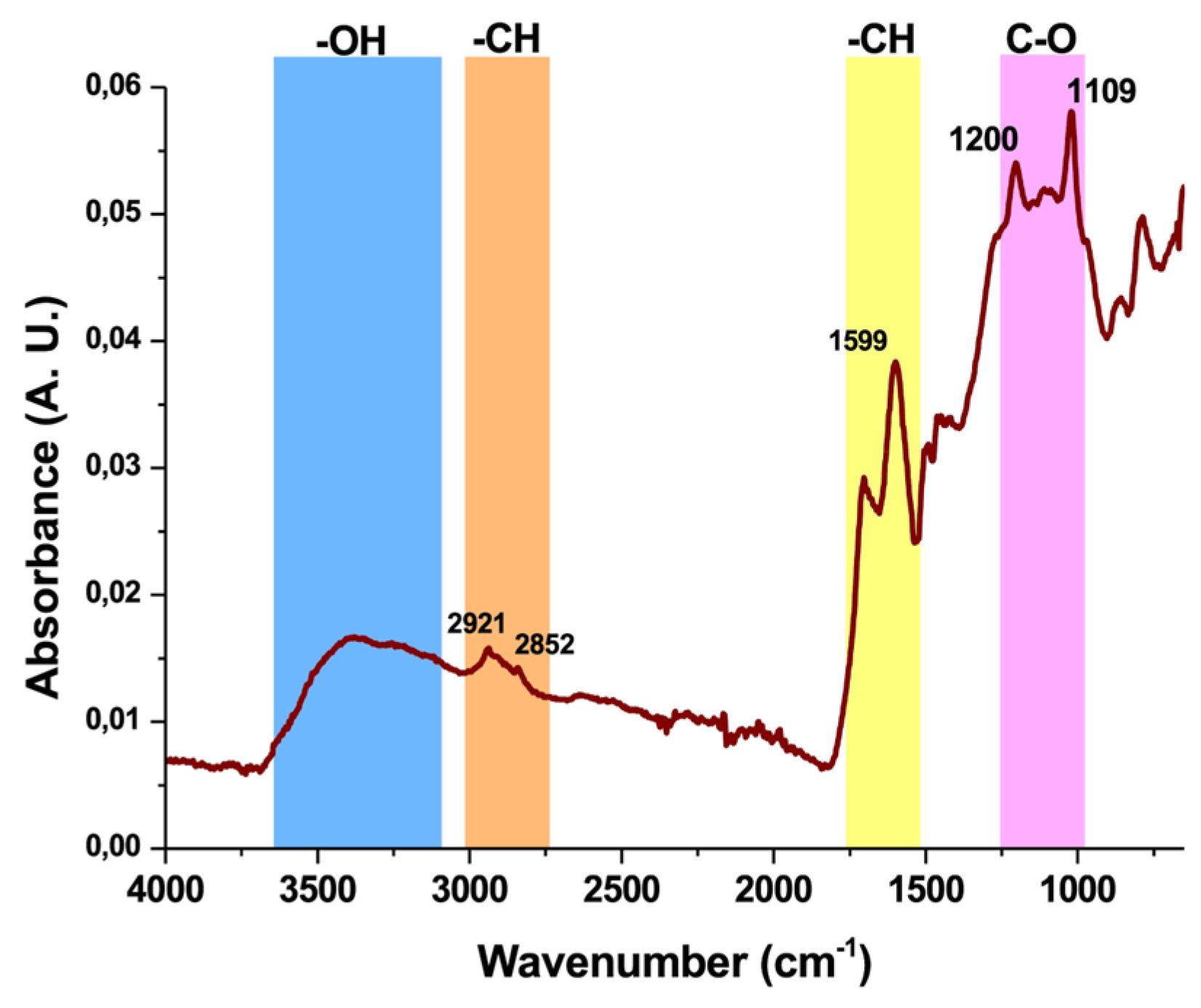
3.1.4.3. FTIR-ATR Characterisation of Klason Lignin from Hazelnut Shells

The FTIR-ATR spectrum of HS-KL displayed the expected signatures of lignin macromolecules. In Figure 4, a broad band around 3300 cm⁻¹ corresponds to O-H stretching vibrations of phenolic and aliphatic hydroxyl groups. Two weaker bands at approximately 2921 and 2852 cm⁻¹ can be assigned to C-H stretching in aromatic and aliphatic moieties [84] . In the fingerprint region, intense bands between 1600 and 1100 cm⁻¹ reflect the lignin aromatic backbone. The peaks at ~1600 and ~1500 cm⁻¹ are associated with aromatic skeletal vibrations, whereas the band at ~1450 cm⁻¹ is related to methoxy groups in guaiacyl and syringyl units, the main lignin monomer types [45] . Furthermore, the peak at1200 cm⁻¹ is attributed to vibrations of methoxy groups and to C-O stretching and deformation in secondary alcohols and aliphatic ethers. Finally, a distinct signal at ~1109 cm⁻¹ may indicate partial incorporation of sulfate groups into lignin molecular structures during the concentrated H₂SO₄ treatment[45] , which is consistent with the Klason method extraction protocol applied in this study (§2.1.1).

3.2. Structural Characterisation of Biohybrid Nanocomposites

3.2.1. Design Logic and Matrix Composition

The overarching goal of this work was to construct biohybrid nanocomposite matrices that, in functional terms, behave like controlled-release formulations: a limited initial burst followed by mid and late phases that can be tuned through material selection and architecture (Figure S4) [73,85,86,87,88] . Rather than encapsulating mineral nutrients, the scaffolds were designed to deliver a polyphenol-rich grape pomace extract as a bioactive cargo for plants. The design therefore mirrors the logic of controlled-release fertilisers (CRF), more than Slow-Release Fertilisers (SRF), in which nutrient release is governed by coating composition, layer structure, and environmental conditions (Figure 5) [89,90,91,92] , but is implemented here using biodegradable polyesters and agro-waste-derived additives.
To this end, four matrices (MatA-D) were engineered by combining two carrier polymers (PHB and PCL), Klason lignin (acid-insoluble fraction) from hazelnut shells (HS-KL) and polyphenols from a grape-pomace extract (GP-PP), using electrospinning and electrospraying (Table 1). The matrices differ systematically in:
  • Polymer phase organisation: single-polymer fibrous networks (PHB) versus multiphase fibrous architectures obtained by the co-deposition of PHB and PCL from separate electrospinning nozzles;
  • Localisation of HS-KL: confined to PHB fibres vs distributed across both PHB and PCL phases vs absent;
  • Localisation of GP-PP: restricted to bead-like depots vs distributed between fibrous networks and bead-like structures
  • Architecture: fibrous networks alone or combined with bead-type depots of different sizes and loading
All matrices were tested at ambient temperature (TA) and at 37 °C (T37) as well as upon short- and long-term exposure to aqueous solutions. In brief (see Table 1 for the full compositions):
  • MatA is a PHB-only scaffold. HS-KL is confined to electrospun PHB fibres, whereas GP-PP are loaded into PHB particles generated by electrospraying (co-deposition). Lignin and polyphenols do not co-exist in the same domains.
  • MatB is a PHB/PCL composite. PHB+HS-KL fibres form the structural network, whereas large PCL+GP-PP particles produced by electrospraying serve as the primary depots (co-deposition). Again, HS-KL and GP-PP reside in different polymer phases.
  • MatC contains both PHB and PCL fibres and PCL bead-on-string segments (co-deposited) in which HS-KL and GP-PP are co-located. Both polymers, therefore, act as carriers for HS-KL-GP-PP microdomains distributed across fibres and beads.
  • MatD has the same PHB/PCL architecture as MatC but contains GP-PP only, with no HS-KL. It provides a reference system in which polyphenols function solely as cargo and plasticisers, without lignin-mediated metering.
These four matrices thus span three key design axes: (i) PHB vs PCL as carrier phases; (ii) presence/absence and placement of lignin; and (iii) segregation vs co-location of HS-KL and GP-PP. This structural diversity underpins the different wetting, swelling, and release behaviours described in the subsequent sections

3.2.2. Polymer Phase and MAF/RAF Microstructure

PHB and PCL are both semicrystalline polyesters, but with distinct thermal windows and microstructures. PHB crystallises readily and has a higher glass transition temperature, whereas PCL is more rubbery at ambient conditions. When electrospun or electrosprayed, both polymers develop the classical three-phase microstructure of semicrystalline polymers: i) crystalline lamellae, ii) a mobile amorphous fraction (MAF), iii) a rigid amorphous fraction (RAF) at crystal interfaces [85,86,87,88,93] . MAF provides the main pathways for water ingress and solute diffusion; RAF is less mobile and behaves as an interfacial “shell” around crystals.
Although detailed crystallinity values were not measured here, the combination of polymer identity, fibre vs bead morphology and processing route suggests a qualitative hierarchy: PHB fibres > PHB beads > PCL fibres > PCL beads, in terms of overall crystallinity/rigidity (more crystals + RAF, less MAF). Coarser PHB fibres tend, therefore, to act as slower, more gated diffusion pathways, whereas PCL beads - especially the larger ones in MatB and the bead-on-string elements in MatC/D - contain the most accessible and continuous MAF and are expected to act as high-capacity depots for polyphenol release.
In practical terms, this means that: i) PHB-rich regions should contribute to structural stability and late-phase gating; ii) PCL-rich regions, particularly beads, should dominate the mid and late portions of the release curves, provided they do not densify excessively during ageing.

3.2.3. Lignin as a Structural and Interfacial Modifier

Within this semicrystalline framework, Klason lignin (HS-KL) plays a dual role. Structurally, its phenolic–aromatic framework can interact with PHB and PCL through hydrogen bonding and π–π interactions, influencing chain packing and crystallisation. Depending on concentration and local environment, HS-KL can: i) act as a nucleating agent, promoting formation of smaller crystals and increasing the RAF fraction; ii) or partially disrupt packing due to its bulky, irregular structure, thereby increasing the continuity of MAF [86,87] .
In either case, HS-KL-containing regions tend to become mechanically stiffer and less prone to uncontrolled swelling, as observed later for fibre swelling at T37. This contributes to the greater morphological stability of matrices that contain lignin in their fibrous framework (MatA-C) compared with the HS-KL-free system (MatD).
At the interface, lignin provides a dense distribution of hydroxyl and aromatic sites that can bind polyphenols via Hydrogen Bonding and π–π stacking (Figure 1C). Where HS-KL and GP-PP are co-located in the same polymer phase (MatC), these interactions: i) help to retain GP-PP within specific microdomains [94,95,96,97] , ii) reduce their ability to plasticise the polyester matrix, and iii) generate “interfacial depots” where diffusion is metered by reversible HS-KL–GP-PP binding.
When HS-KL and GP-PP are spatially separated (MatA and MatB), lignin still improves fibre stability and wettability but cannot directly meter depots, so its effect on release is more indirect.

3.2.4. Polyphenol Mixture and Expected Partitioning

The grape-pomace extract used here contains several polyphenol classes (Table 2), which span a broad polarity range (Table S5): i) small, highly hydrophilic molecules such as gallic and 4-hydroxybenzoic acids, ii) anthocyanins, generally hydrophilic and cationic/zwitterionic near neutral pH, iii) intermediate-polarity flavonols (e.g., catechin-derived structures), iv) more hydrophobic species, including stilbene-type molecules.
On the basis of their polarity and aromaticity, a simplified partitioning picture can be drawn: i) hydrophilic acids and anthocyanins preferentially reside in hydrated MAF regions and near HS-KL-rich interfaces, ii) flavonols can bridge between HS-KL-rich domains and more hydrophobic segments of PHB/PCL, iii) hydrophobic stilbene-like species tend to partition into less hydrated, more hydrophobic MAF (PCL > PHB), again interacting strongly with lignin where present.
Accordingly, in matrices where HS-KL and GP-PP are co-located (MatC), one expects a hierarchy of retention: hydrophilic acids and anthocyanins form relatively labile, early-releasing complexes; flavonols and stilbenes are held more strongly and contribute disproportionately to the mid and late phases. In HS-KL-free matrices (MatD), the same compounds act mainly as plasticisers: they ease chain mobility and water uptake but are less effectively “held back” by specific binding, so structural changes can outpace controlled metering.

3.2.5. Architecture, Porosity and Transport Pathways

Finally, the assembly of fibres and depots into 3D scaffolds controls porosity, pore connectivity, and the transport pathways available to water and solutes. In MatA, an open PHB fibrous mesh is decorated with relatively small PHB+GP-PP particles. Porosity and inter-fibre channels are abundant. Fibres carry HS-KL, whereas GP-PP is stored in separate particles, which act as soft depots embedded in a PHB gate. In MatB, PHB+HS-KL fibres form a structural “skeleton” interspersed with large PCL+GP-PP beads. The bead inventory is high, and the particle-to-fibre size ratio is large, so PCL depots are expected to dominate both mid and late release once hydrated, whereas PHB+HS-KL fibres constrain overall swelling. MatC combines PHB and PCL fibres with smaller PCL beads in a more compact, intertwined network. Because both fibres and beads carry HS-KL+GP-PP, the architecture contains many parallel HS-KL-GP-PP depots distributed throughout a relatively tight mesh. MatD has a similar fibre-and-bead layout, but with GP-PP only. The absence of HS-KL allows polyphenols to plasticise both PHB and PCL to a greater extent, predisposing the network to greater swelling, pore narrowing, and bead compaction during prolonged hydration.
From a transport perspective, fibres provide long-range pathways and define pore throats, while beads and bead-on-string segments are expected to act as local reservoirs. Swelling of fibres tends to narrow pores and increase tortuosity, whereas bead shrinkage or loss can decrease depot volume or locally open channels. The balance between these opposing trends - modulated by polymer phase, HS-KL placement, and GP-PP composition - ultimately generates the different burst-mid-late profiles observed at TA and T37.

3.3. Morphological Characterisation of the Bio-Based Nanohybrids

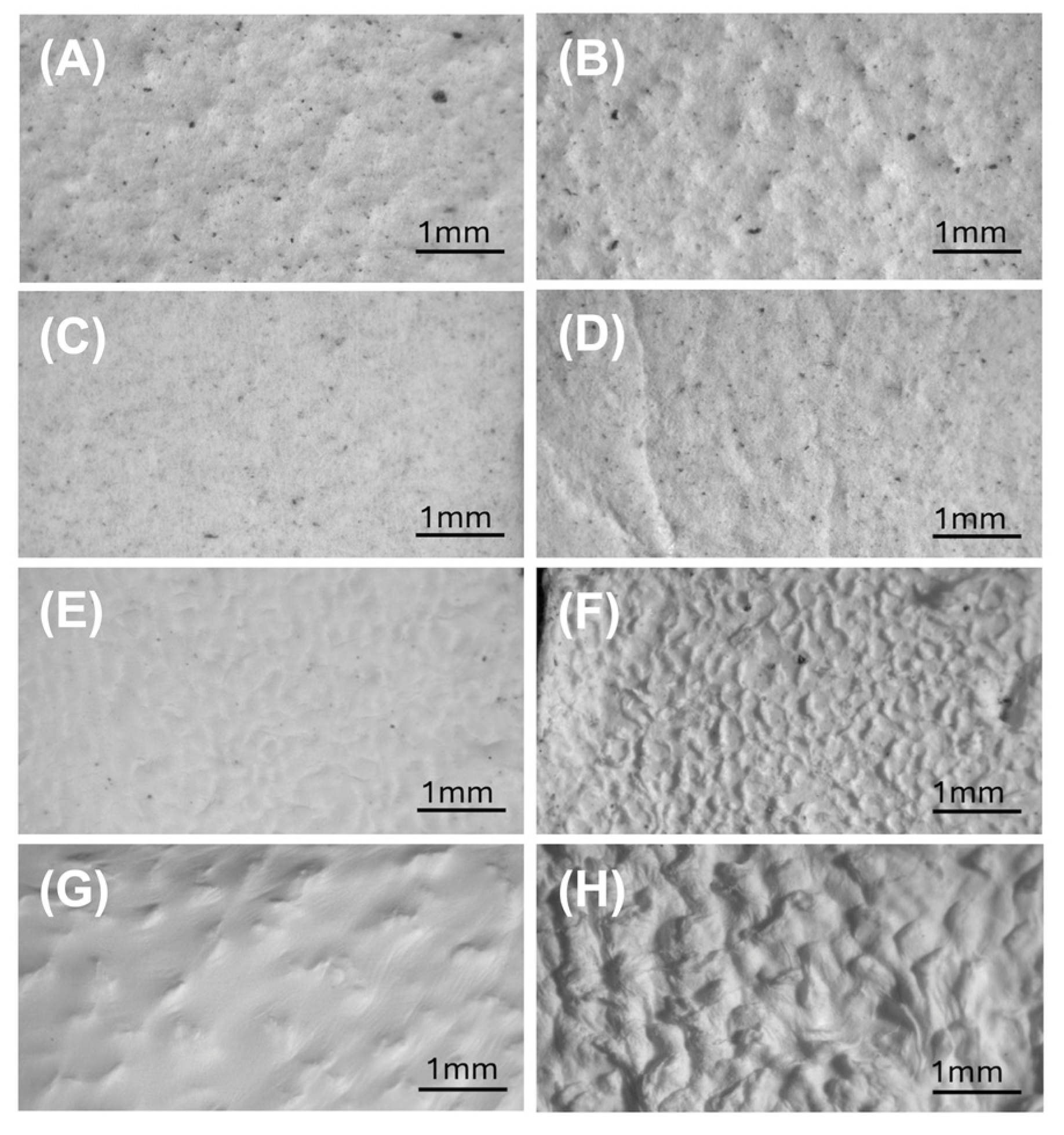
3.3.1. Stereomicroscopy

Bulleted stereomicroscopy provided an initial low-magnification overview of scaffold architecture before and after 14-day soaking in 0.11 M phosphate buffer (pH 7.4) at T37, i.e., under the same conditions used for the release tests. All mats appeared macroscopically continuous, but surface texture and graininess differed (Figure 6).
Before 14-day soaking in 0.11 M phosphate (pH 7.4), MatA and MatB (Figure 6A,C) showed a relatively rough, granular surface with numerous dark particles, whereas Mats C and D (Figure 6E,G) were smoother, with MatC often displaying a convoluted, “brain-like” topography and MatD a more silky, weakly wrinkled aspect. Immersion in 0.11 M phosphate buffer (pH 7.4) for 14 days generally increased surface roughness, particularly in Mats B-D, where depressions and ridges became more pronounced (Figure 6D,F,H). Given that all scaffolds are nanofibrous, this increased roughness is consistent with partial fibre swelling, collapse, and local surface fusion. Dark grains were abundant and broadly distributed in Mats A-C, but essentially absent in MatD. Microscopical observations at the millimetre scale do not show an evident decrease in the surface density of dark lignin-rich domains after 14 days of immersion at 37 °C, except for MatA.

3.3.1. Optical Microscopy

Optical microscopy, at higher magnification, emphasised the nanofibrous contribution to the architecture and refined the stereomicroscopic observations (Figure 7).
In Mats A and B (Figure 7A,C), a dense PHB fibre network was visible, with fibres of different diameters interlaced with darker, more compact domains corresponding to the bead-like depots. The presence and distribution of dark lignin-rich grains observed by stereomicroscopy were also confirmed after 14-day soaking in 0.11 M phosphate buffer. (pH 7.4)
In MatC, the unsoaked scaffold appeared as a clear, finely entangled fibrous web. After immersion, its surface acquired a characteristic convoluted, “brain-like” appearance, consistent with limited fibre coalescence and local reorganisation at the surface, without gross collapse of the fabric (Figure 7E,F). In MatD, the lignin-free network exhibited broader wrinkles even before 14-day soaking; these became more pronounced thereafter, consistent with a softer, less rigid framework that is more prone to macroscopic deformation (Figure 7G,H). The contrast between MatC and D at this scale already suggests that lignin contributes to mechanical rigidity and resistance to large-scale distortion.

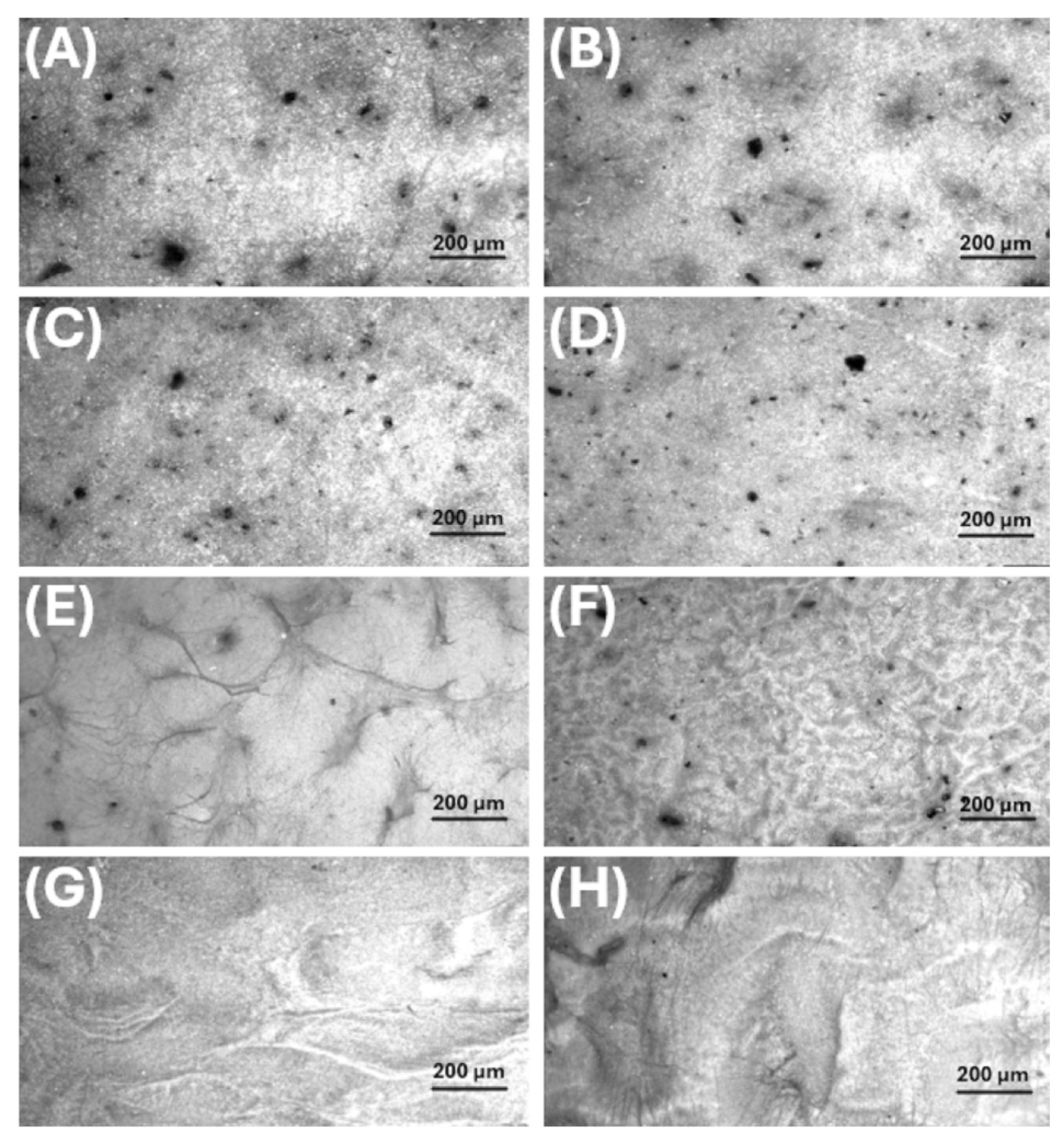
3.3.3. SEM Analysis: Fibres and Particles Before and After Soaking

SEM provided a detailed view of the multi-scale morphology of each scaffold, allowing fibre and bead dimensions to be quantified (Table 4) and their evolution on prolonged immersion in 0.11 M phosphate buffer (pH 7.4) at T37 to be assessed. (Figure 8 and Figure 9; Table 4).
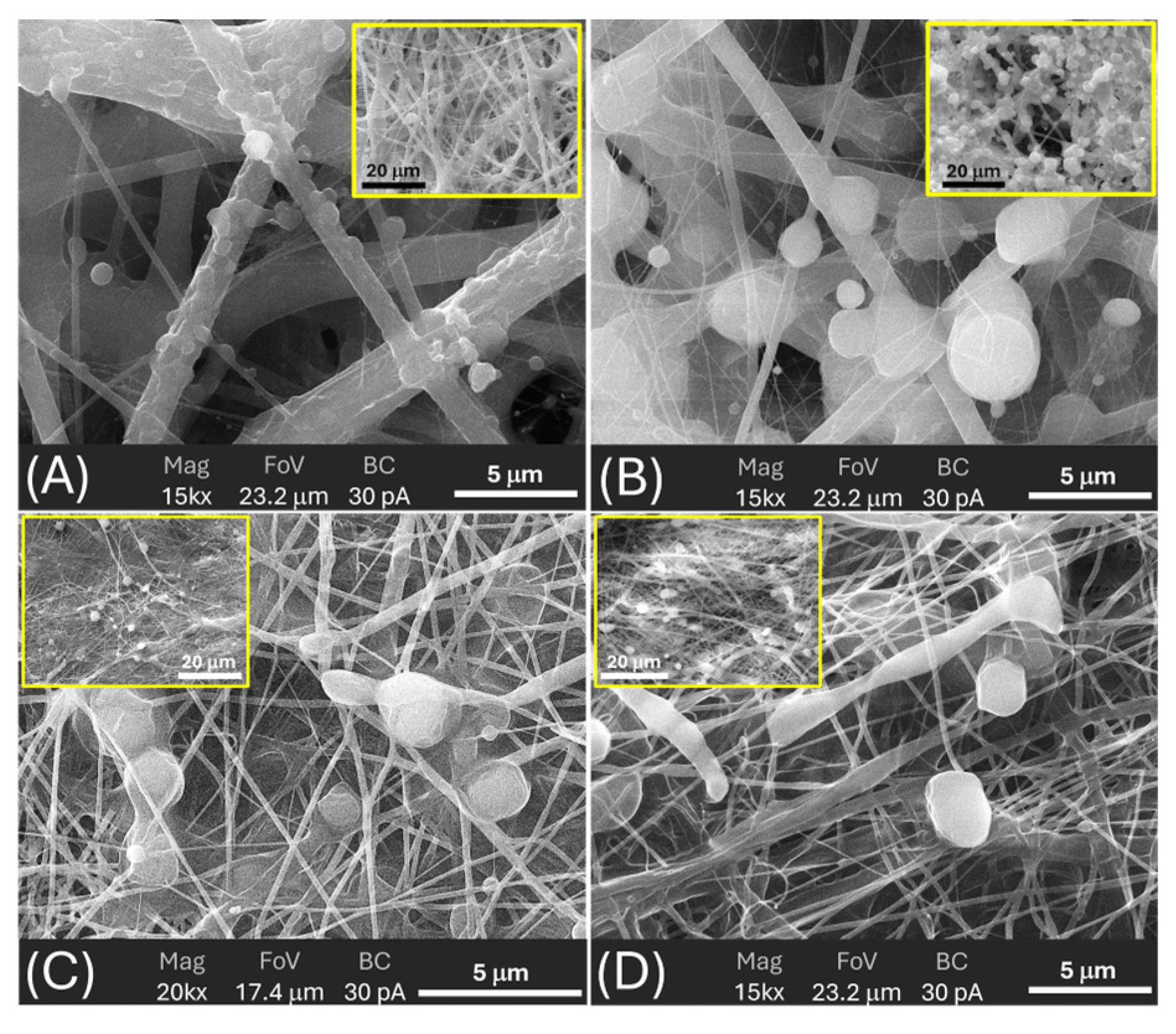
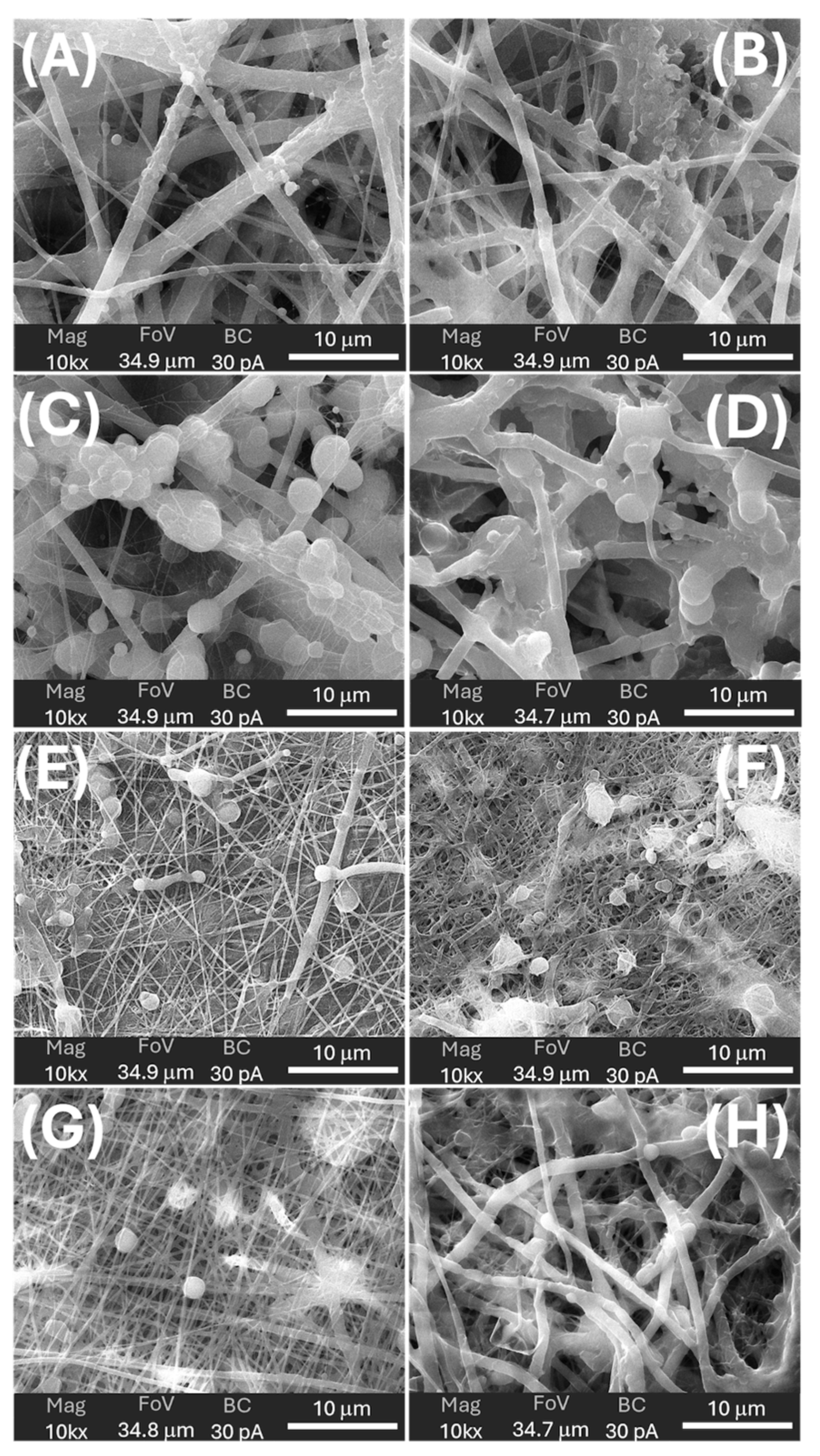
  • MatA (PHB+HS-KL fibres, PHB+GP-PP beads). The pristine MatA consisted of a randomly oriented PHB fibre network (mean diameter ≈1.0 µm, CV ≈2%) decorated by relatively small PHB-based particles (mean area ≈1.0 µm2, CV ≈42%) distributed along fibres of different sizes (Figure 10A, 11A; Table 4). The overview images showed an open network with visible inter-fibre voids and bead-like elements anchored to both thicker fibres and very thin nanofibres, indicating strong adhesion between electrosprayed PHB particles and electrospun PHB fibres (Figure 8A inset). After 14 days in 0.11 M phosphate buffer (pH 7.4) at T37, fibres in MatA were clearly swollen: the mean diameter increased by ~32%, and inter-fibre spaces narrowed, consistent with water uptake and partial relaxation of the PHB network (Figure 9B). In contrast, the average particle area and particle roundness changed only minimally (~6%), and total particle area increased slightly (~3%), indicating that PHB beads behaved as soft, shape-preserving depots rather than densifying entities (Table 4). Morphologically, MatA thus evolves towards a more compact fibrous mesh with stable, small PHB depots.
  • MatB (PHB+HS-KL fibres, large PCL+GP-PP beads). In MatB, PHB fibres (mean diameter ‚ ≈1.2 µm) formed a porous, multi-diameter network similar in scale to that of MatA but interspersed with large PCL-based spherical particles (mean area ≈7.6 µm2), often partially fused or embedded in a surrounding polymer matrix (Figure 10B, 11C; Table 4). At low magnification, these beads dominated the architecture, producing a pronounced fibre-bead multi-scale structure (Figure 8B inset). Very thin PCL nanofibres, originating from the electrosprayed PCL solution, were occasionally observed but were excluded from the diameter statistics (Figure 10B, 11C). Upon 14-day soaking in 0.11 M phosphate buffer (pH 7.4), PHB fibres in MatB swelled moderately (+17%), and some large fibres showed surface roughening or local damage, suggesting structural relaxation and mild degradation (Figure 9D; Table 4). The small PCL nanonet visible in the pristine material was no longer detectable, suggesting its collapse or dissolution. The most striking change concerned the PCL particles: their mean area and total particle area both decreased by ~36%, while roundness remained essentially constant. This pattern indicates significant in-place densification and shrinkage of PCL depots rather than their detachment. MatB, therefore, shifts from a fibre-supported network with large, soft depots to a structure with swollen fibres and more compact PCL beads.
  • MatC (PHB+PCL fibres with HS-KL+GP-PP, PCL+HS-KL+GP-PP beads-on-string). MatC was produced by co-electrospinning PHB and PCL solutions containing both HS-KL and GP-PP, yielding a single, integrated fibrous architecture in which PHB and PCL fibres were physically entangled (Figure 10C, 11E). The mean fibre diameter was much smaller than in A and B (≈0.23 µm, 3-5-fold thinner), and the network appeared dense and homogeneous (CV ≈26%) (Table 4). Rounded and ellipsoidal features along PCL fibres were interpreted as bead-on-string structures (mean area ≈0.8 µm2, CV ≈58%), providing a fine population of depots embedded in the fibrous matrix. Top-view images emphasised a compact, membrane-like appearance with limited apparent surface porosity (Figure 8C inset). After 14-day soaking in 0.11 M phosphate buffer (pH 7.4), fibre diameter increased only slightly (+5%), and fibres showed limited coalescence and mild surface roughening, confirming a restrained swelling behaviour (Figure 9F). The average bead area remained essentially unchanged (+0.5%), but total bead area dropped by about 22%, indicating the loss or detachment of a fraction of bead-on-string segments rather than bead shrinkage (Table 4).
Roundness increased modestly (+5%), suggesting that the remaining beads were slightly smoothed. Overall, MatC retains a compact fibrous backbone with a reduced but still finely distributed bead population, the main morphological change being a selective loss of PCL(HS-KL+GP-PP) depots rather than gross densification.
  • MatD (PHB+GP-PP and PCL+GP-PP fibres, PCL+GP-PP beads, no lignin). MatD, co-electrospun from PHB+GP-PP and PCL+GP-PP solutions, comprised an open, highly entangled fibrous mesh with thin fibres (mean diameter ≈0.28 µm) and PCL-based beads (mean area ≈2.8 µm2) that were less embedded and more superficially located than in MatC (Figure 10D, 11G; Table 4). Low-magnification views revealed a looser network with greater apparent porosity and lower internal cohesion (Figure 8D inset). Prolonged soaking in 0.11 M phosphate buffer (pH 7.4) for 14 days induced the most dramatic changes among all scaffolds. Fibre diameters increased by about 175%, and the finer nanofibrous elements largely disappeared, replaced by thickened, swollen strands and partially collapsed bundles (Figure 9H; Table 4). The mean bead area and total bead area decreased by ~23%, and bead roundness dropped (~−7%), consistent with notable surface erosion and bead densification within a strongly plasticised network. Morphologically, MatD evolves into a swollen, partially collapsed structure with fewer, more irregular depots and a substantially altered pore architecture.

3.3.4. Role of Matrix Components in Scaffold Architecture and Stability

The four scaffolds described above by SEM observations (Figure 8 and Figure 9; Table 4) confirm that the three main components, i.e. carrier polymers, lignin and polyphenols, contributed in distinct and complementary ways to the final architecture and its stability in water.
  • Carrier polymers (PHB vs PCL): Comparing the four scaffolds highlights the distinct roles of PHB and PCL as carrier phases. PHB-based fibres in Mats A and B formed the thickest backbones and exhibited moderate swelling at T37, whereas the mixed PHB/PCL fibres in Mats C and D were initially much thinner and thus more prone to dimensional change when plasticised. However, the presence or absence of lignin and GP-PP strongly modulated this tendency: MatC, with HS-KL+GP-PP in both PHB and PCL phases, showed only minimal fibre thickening, while MatD, with GP-PP only, displayed extreme swelling. PCL-based depots were systematically larger than PHB-based ones (MatB > MatD > MatC > MatA) and, in MatB and MatD, underwent clear shrinkage on 14-day soaking in 0.11 M phosphate buffer (pH 7.4), indicating significant densification. In MatC, by contrast, bead size was preserved, and the reduction in total bead area resulted from loss rather than compaction.
  • Role of lignin: Lignin influenced both morphology and stability. In fibres, its presence in MatA–MatC was associated with limited swelling upon 14-day soaking, whereas the lignin-free MatD exhibited pronounced fibre thickening and partial collapse of the nanofibrous network. This is consistent with lignin stiffening the amorphous phase of PHB and PCL and resisting water-driven expansion. In beads, the effect was more nuanced. PHB+GP-PP depots in MatA (no lignin) retain their size; PCL+GP-PP depots in MatB (no lignin) shrank markedly; PCL(HS-KL+GP-PP) beads in MatC largely retained their size but suffered some detachment.
  • Role of polyphenols: Polyphenols behave as both cargo and internal plasticiser. When they are widely distributed in fibres and beads without lignin (MatD), their largely hydrophilic character favours water uptake and chain mobility, leading to strong fibre swelling, bead erosion and a looser, partly collapsed architecture (pore narrowing and increased tortuosity). When co-localised with lignin (MatC), they instead contributed to more compact fibres and beads, consistent with the formation of lignin–polyphenol complexes reported in the literature. In depots, GP-PP combined with PCL generates very large beads in MatB that subsequently densify on 14-day soaking at T37, whereas GP-PP co-loaded with lignin in PCL beads (MatC) yields smaller, dimensionally stable depots (for HS-KL-GP-PP complexes), whose main change is partial loss from the web rather than shrinkage, with bead loss providing an additional pathway for cargo release. In PHB+GP-PP beads (MatA), the GP-PP load does not drive significant compaction, and the depots are small and soft.
3.3.4.1. Concluding Remarks
Taken together, the morphological data indicate that: i) PHB primarily defined the stiffness and connectivity of the fibrous framework (porosity), whereas PCL provided high-capacity depots whose size and evolution (stable, shrinking, or detachable) differed across architectures and were later reflected in the mid and late components of GP-PP release; ii) Lignin acted as a structural stabiliser in fibres and as a modifier of depot behaviour: it limited fibre swelling and promoted depot integrity, but could shift the balance between shrinkage and loss; iii) Polyphenols, depending on where and with whom they were co-located, either plasticised and destabilised the network (GP-PP-only architectures) or, when complexed with lignin, contributed to more rigid, metered depots.
Hence, each matrix approached the release tests with different features, which precisely translated into the observed burst, mid, and late polyphenol-release behaviours (§3.4 and §3.5): MatA as a PHB scaffold with stable small depots; MatB as a PHB backbone filled with large, densifying PCL depots; MatC as a compact PHB/PCL web with small, lignin-rich depots, some of which could detach; and MatD as a highly swellable GP-PP-rich network. These preset architectural differences

3.4. Interactions Between Nanohybrid Scaffolds and Water

Here, we link early wetting (water contact angle and water uptake) at TA with the longer-term structural evolution of the architectures, including the stress test at 37 °C. Water uptake is the first step that activates polyphenol release from the scaffolds.

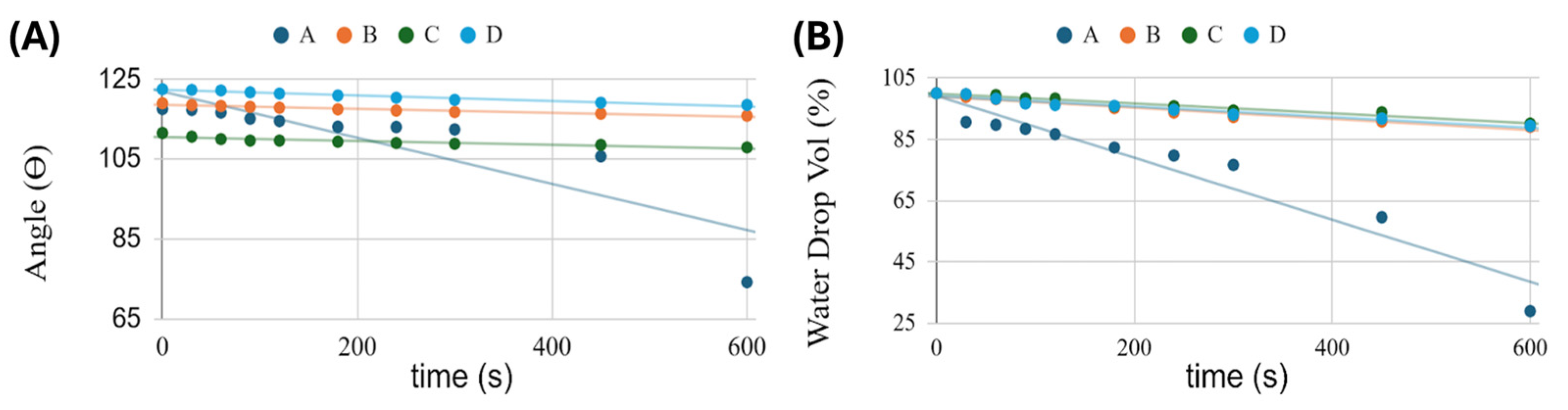
3.4.1. Early Wetting and Hydration (0–10 min, TA)

Dynamic water contact angle (WCA) and droplet-volume (WDV) decrease measurements at TA were used to explore the outer skin of each scaffold as it hydrated in the first minutes. It is well known that both surface chemistry and roughness control wetting behaviour and can strongly influence a material’s WCA [98,99,100,101]. At deposition (t0), all matrices showed high WCA values (≈112–123°) (Figure 10A), consistent with rough, porous and overall hydrophobic electrospun ± electrosprayed surfaces. The slight ranking (MatD most hydrophobic - 122.5°, MatC least - 111.6°) reflects differences in PHB/PCL ratio and additive content, but all four start in a Cassie-like state, with the droplet supported by asperities and air trapped beneath.
Over 10 min, however, their trajectories diverged (Figure 10B). For MatB, MatC, and MatD, the WCA decreased only slightly (≈3°), and WDV decreased by about 10%, values that can be explained by evaporation from a droplet with a largely pinned contact line and only modest superficial hydration [102,103] . In contrast, MatA showed a marked decrease in WCA (~118° to ~75°) and a ~70% apparent droplet-volume loss. Evaporation alone cannot account for such a large volume change [99,101,102,104] , indicating significant capillary uptake into the scaffold beneath the droplet and a partial Cassie-to-impregnating/Wenzel transition [98,100,101] .
This behaviour is consistent with the matrix architectures and additive localisation described in §3.2 and §3.3. MatA consists of an open PHB+HS-KL fibrous network decorated with small PHB+GP-PP beads. Both lignin-containing fibres and GP-PP-loaded particles are accessible at or near the surface. HS-KL introduces polar sites that facilitate hydration, while the small PHB+GP-PP depots are not locked into HS-KL–GP-PP complexes and remain relatively soft. Under a droplet, water can rapidly penetrate into these near-surface domains, swell the fibres locally, and fill air pockets, thereby increasing the solid–liquid contact area and significantly lowering the apparent WCA.
In MatB, MatC and MatD, the surface “seen” by the droplet is more sluggish on this timescale. In MatB, large PCL+GP-PP beads dominate the interface and hydrate more slowly; HS-KL is confined to PHB fibres that are only partially exposed. In MatC, HS-KL and GP-PP are co-located in both PHB and PCL phases, forming complexes that stiffen the amorphous regions and suppress rapid swelling. In MatD, GP-PP is present throughout PHB and PCL fibres and beads; however, during the first 10 min at ambient conditions, the hydrophobic backbone and limited chain mobility still prevent significant volumetric rearrangements. As a result, WCA and WDV for MatB-MatD remain essentially in an evaporation-dominated regime over 10 min.
In summary, early WCA and droplet-volume data indicate that MatA is intrinsically prone to rapid near-surface hydration and restructuring, whereas MatB-MatD remain comparatively inert on the minute timescale. As shown later (§3.5 and §3.6), this short-term “reactivity” is mechanistically informative but not directly predictive of the long-term release hierarchy.

3.4.2. Long-Term Hydration at Ambient Temperature: Conceptual Extrapolation

Direct morphological measurements were performed after 14 days of immersion at T37, whereas at TA, only the first 10 min were monitored using WCA and droplet-volume analysis. Nevertheless, combining early wetting at TA with the T37 morphology data (Table 4) and the TA vs T37 release profiles provides a qualitative picture of how the architectures likely evolve under prolonged hydration at TA.
Polymer physics suggests that the same processes observed at T37 - fibre swelling, secondary crystallisation (MAF-to-RAF conversion), depot densification or detachment - also occur at TA, but more slowly and to a smaller extent, because chain mobility and diffusivity are lower. This interpretation is consistent with the systematic finding that, across all matrices, total polyphenol release and late tail areas are larger at TA than at T37: after 14 days at TA, the networks remain less tightly packed and retain more accessible amorphous pathways for diffusion.
Starting from the early wetting hierarchy (MatA ≫ MatB ≈ MatC ≈ MatD), one can infer the following qualitative evolution at TA:
  • MatA - The PHB+HS-KL fibrous backbone with small PHB+GP-PP depots is expected to enter a moderately swollen state, with fibres thickening and inter-fibre pores narrowing, but without strong depot densification. The overall morphology should remain relatively open compared with its T37 counterpart, supporting a balanced burst-mid-late profile with a modest total release;
  • MatB - Large PCL+GP-PP depots that sharply densify at T37 will hydrate and reorganise more slowly at TA, so secondary crystallisation and volume loss are likely incomplete after 14 days. PHB+HS-KL fibres will still swell to some extent, but pore constriction will be less pronounced than at T37. This is compatible with MatB showing the highest total and late release at TA: the depots are plasticised but not yet fully compacted, and a substantial mobile amorphous volume remains;
  • MatC - At T37, MatC shows minimal fibre swelling and a reduction in total bead area mainly due to detachment of some PCL(HS-KL+GP-PP) bead-on-string segments. At TA, HS-KL-GP-PP complexes will still limit swelling and chain mobility, while mechanical stresses are milder; fibre diameters should increase only slightly, and bead detachment should be less extensive. The hydrated architecture after 14 days at TA is therefore expected to stay close to the original, compact state, with a well-preserved population of HS-KL-GP-PP depots. This matches the high total release and particularly strong late contribution observed for MatC at TA.
  • MatD - The GP-PP-only PHB/PCL network that swells dramatically and partially collapses at T37 will also move towards a swollen, more tortuous morphology at TA, but with less extreme pore closure. Fibres will still thicken more than in the lignin-containing matrices, and PCL+GP-PP beads will densify, yet the lower temperature implies reduced swelling and compaction. This is consistent with MatD remaining the weakest releaser at both temperatures: even under gentler conditions, a sizeable fraction of GP-PP remains trapped in a highly plasticised, partially collapsed network
Conceptually, then, prolonged hydration at TA preserves the relative structural ranking seen at T37 -MatC compact and robust, MatD swollen and fragile, MatA and MatB in between—but with smaller deformations and more open diffusion pathways, explaining the larger total and late releases at TA for all matrices.

3.4.3. Morphological Evolution Under Prolonged Hydration (14 d, 37 °C)

The 37 °C immersion data provide a quantitative reference for how the scaffolds age under more demanding thermal conditions. After 14 days in buffer at T37, all matrices showed signs of structural reorganisation, but to varying degrees (Figure 10 and Figure 11; Table 4).
Fibre diameters followed a clear swelling hierarchy: MatC exhibited the smallest increase (~5 %), MatB and MatA showed moderate thickening (~17 % and ~32 %, respectively), and MatD underwent extreme swelling (~175 %). This pattern is consistent with the roles of lignin and polyphenols described in Section 3.3. Lignin-containing fibres (MatA–MatC) are partially stabilised by π–π and H-bond networks with PHB/PCL, which restrain expansion, while GP-PP-only fibres in MatD are strongly plasticised and draw in much more water. Within the lignin-containing group, the PHB/PCL blend of MatC appears least prone to water-driven expansion (due to extensive HS-KL–GP-PP complexation), whereas the PHB-only network of MatA is more responsive.
Bead populations also evolved in matrix-specific ways. In MatA, PHB+GP-PP depots retained their mean size and total area, indicating that they remained soft but did not densify appreciably. In MatB, large PCL+GP-PP beads shrank markedly in both mean and total area, consistent with in situ densification driven by GP-PP loss, secondary crystallisation and collapse of residual microvoids. In MatC, PCL(HS-KL+GP-PP) beads showed almost unchanged mean area but a substantial reduction in total bead area (~22%), implying that a fraction detached from the fibrous web rather than shrinking in place. In MatD, PCL+GP-PP beads shrank in both mean and total area (~23%), but now within a highly swollen fibre web, indicating depot compaction inside a gel-like, GP-PP-rich matrix.
These coupled changes in fibre swelling and depot evolution have direct consequences for transport pathways and, ultimately, for release behaviour (Section 3.5). Moderate swelling with stable depots (MatA) yields a conservative, self-limiting profile; strong depot densification (MatB) front-loads release and weakens the late tail; minimal swelling with partial depot loss (MatC) preserves a compact network yet shifts some release to earlier times while maintaining the best late fraction; and extreme fibre swelling plus depot compaction (MatD) produces a tortuous, partially collapsed architecture that severely restricts overall polyphenol discharge.
In the following section, these hydration and ageing patterns are explicitly linked to the burst, mid and late release components at both TA and T37.

3.5. Polyphenol Release from the Biohybrid Nanostructures

The electrospun ± electrosprayed scaffolds were designed as biohybrid matrices that release a grape pomace polyphenol (GP-PP) extract in a controlled manner. Four architectures were tested (MatA-D), differing in polymer phase (PHB vs PCL blends), lignin (HS-KL) content and localisation, and GP-PP distribution between fibres and bead-like depots (Table 1). Polyphenol release was quantified at TA and T37, and the resulting profiles were analysed in terms of burst, mid and late phases, total released area and t50, as described in §2.7. A schematic of typical CRF release profiles under unimodal/monomodal, bimodal, and multimodal models is shown in Figure S4, which also displays the different release phases [105]. Typically, the cumulative curves of CRF vs SRF vs traditional fertilisers exhibit sigmoidal shapes [106] (Figure 5). Similarly, the cumulative curves of the matrices created here were sigmoidal, with visible inflexion points, confirming that the scaffolds behave as CRF-like systems rather than as simple diffusive slabs.

3.5.1. Release Profiles at Ambient Temperature (TA)

At TA, all matrices showed a clear multimodal release with a burst phase, containing a modest peak at ≈24 h, a mid phase, containing the second pronounced peak centered at ~120-144 h, and the late tail, containing the third peak at ~240-264 h plus the terminal shoulder at ~336 h (Figure 11A). In terms of total GP-PP released (integrated area), the ranking at TA was: MatB > MatC > MatA > MatD (≈57.1 > 49.4 > 41.4 > 34.8 a.u., respectively) (Table 5). The early burst, mid, and late regions followed the same order in absolute area (MatB > MatC > MatA > MatD), whereas t50 values clustered between ≈140 and 148 h, with MatA being the slowest and MatD the fastest to reach 50% of its own cumulative release, hence highlighting that MatB maximises throughput, MatC balances throughput and control, MatA constrains delivery, and MatD illustrates that GP-PP-only networks are poorly controlled-release carriers. The cumulative curves of the matrices exhibited a sigmoidal shape with visible inflexion points, corresponding to the release peaks described before (Figure 11B).
On a day-by-day basis, the normalised daily release trends at TA (Figure 12A) show that MatB is the dominant contributor on roughly half of the sampling days (7/14), MatC leads on 3 days, and on the remaining days, MatB and MatC contribute comparably. MatD is consistently the weakest contributor (with the lowest daily share on 12/14 days), whereas MatA occupies an intermediate position throughout the test period. This confirms that the higher integrated areas of MatB and MatC reflect genuinely stronger performance across the entire two-week window rather than being driven by a single transient event.
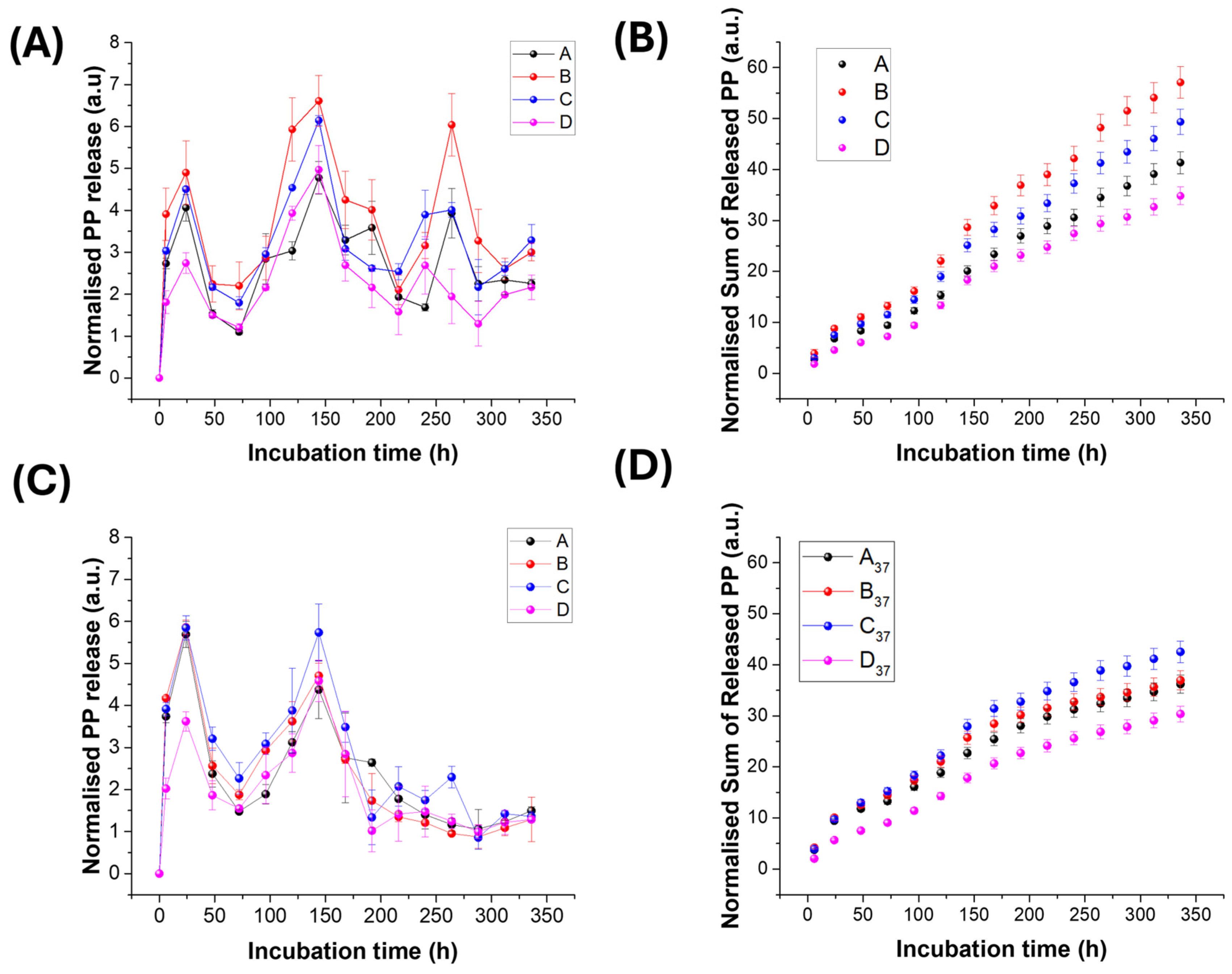
  • MatA (PHB+HS-KL fibres + PHB+GP-PP depots, no HS-KL-GP-PP co-location). MatA delivered an intermediate total amount (41.4 a.u.; Table 5), with a modest burst, a moderate mid contribution and a medium late tail. The cumulative curve is clearly multimodal but with a relatively shallow slope (Figure 11B). The latest t50 (≈148 h; Table 5) of MatA reflects diffusion through a PHB-only network in which HS-KL stabilises the fibres but does not directly meter the GP-PP depots. Release is governed by slow diffusion from PHB beads and by the porosity set by fibre diameter and bead coverage. Overall, MatA behaves as a conservative, low-dose scaffold with a relatively delayed response.
  • MatB (PHB+HS-KL fibres + large PCL+GP-PP depots, segregated HS-KL and GP-PP). At TA, MatB was the most productive matrix overall (total = 57.1 a.u.; Table 5), combining the largest burst (13.3 a.u.), mid (23.7 a.u.) and late (20.2 a.u.) areas. Although its burst was the strongest among the four matrices, it still represented only a minority of the total release, with most of the mass delivered in the mid and late windows. The cumulative curve for B therefore rises steeply but not explosively and clearly dominates those of the other scaffolds (Figure 11B). This behaviour reflects its architecture: PHB+HS-KL fibres provide a relatively stable supporting network, while the large PCL+GP-PP depots act as high-capacity, MAF-rich sources that are easily hydrated and drained at TA. Because HS-KL resides only in the PHB phase, it primarily stabilises the fibrous mesh rather than metering GP-PP within the PCL beads; as a result, MatB functions as a high-throughput system with strong mid and late contributions, suitable where a relatively high dose of polyphenols over 1-2 weeks is desired, even if fine control over tail "quality" is less critical.
  • MatC (PHB+PCL fibres and PCL beads, all with HS-KL+GP-PP co-located). MatC released somewhat less GP-PP than B (49.4 a.u.; Table 5) but with a smoother profile and a particularly strong late contribution. Burst and mid phases were high, and the late tail was second only to MatB in absolute terms but largest in relative terms (late/total). The cumulative curve of MatC tracks just below that of MatB (Figure 11B). Here, HS-KL and GP-PP share the same microdomains in both PHB and PCL phases, so HS-KL-GP-PP complexes meter desorption and stabilise labile species (anthocyanins and flavonols). The architecture behaves as a system of parallel depots distributed in fibres and beads, providing a broad, well-structured burst-mid-late sequence. At TA, MatC is thus slightly less productive than MatB in total mass but more controlled and better suited when the quality and persistence of the late phase are important.
  • MatD (PHB+PCL fibres and PCL beads, GP-PP only, no HS-KL). MatD, despite the highest nominal GP-PP loading, gave the lowest total release at TA (34.8 a.u.; Table 5), with the smallest burst and late areas. The cumulative curve lies clearly below those of the other systems (Figure 11B). The absence of HS-KL means that GP-PP primarily acts as a plasticiser for PHB and PCL; the network swells and softens rather than forming well-defined, stabilised depots. As a result, the scaffold is structurally quite responsive but functionally inefficient: pathways become tortuous, and a significant fraction of GP-PP remains trapped. MatD is therefore the least effective matrix at TA, despite its apparent "capacity".
Overall, the TA data show that long-term performance depends far more on polymer phase, depot morphology and HS-KL placement than on loading alone. MatB maximises throughput; MatC balances throughput and control; MatA constrains delivery; and MatD demonstrates that GP-PP-only networks are poorly controlled-release carriers.
A summarised description of matrix-by-matrix features at TA is reported in Table S5.

3.5.2. Release Profiles at 37 °C

Incubation at 37 °C represents a realistic warm-soil scenario for shallow Mediterranean horizons and a useful stress test for the scaffolds (§S6) [107,108,109,110,111,112,113,114,115,116,117] . At this temperature, water and solute mobility increase, but polymer reorganisation (swelling, secondary crystallisation, depot densification or detachment) is also accelerated. Across all matrices, peak fitting and cumulative curves revealed three general trends (Figure 11; Table 5): i) Total release decreased relative to TA (≈ -12 to -35%, depending on the matrix). ii) Late tails were strongly suppressed (≈ -34 to -66 %), so that the clear multimodal profiles were compressed. iii) t50 shifted to earlier times (≈103-125 h vs 140-148 h at TA), indicating that the PP released tends to do it sooner, before structural tightening fully develops. The ranking at T37 was: i) Total area: MatC > MatB > MatA > MatD; ii) Burst and mid areas: MatC > MatB > MatA > MatD; iii) Late area: MatC > MatA > MatD > MatB; iv) t50: MatB < MatC < MatA < MatD. The GP-PP release profile exhibited a multimodal shape also in this case, with a burst phase, containing an increased peak at ≈24 h, relative to TA, the mid phase, containing the second peak at ~120-144 h, and the late tail, containing the third peak at ~240-264 h plus the terminal shoulder at ~336 h.
  • MatA - At T37, MatA exhibited a modest reduction in total release (~−12 %) and a marked decrease in late-area (~−43.5 %), while its burst increased by 25.3% relative to TA, and t50 decreased from 148.3 h to 118.5 h (Table 5). PHB+HS-KL fibres swell and undergo secondary crystallisation, narrowing diffusion pathways, while PHB+GP-PP depots remain relatively soft but progressively less accessible. The profile becomes more front-loaded (larger early contribution, weaker tail), consistent with a scaffold that reacts quickly to warming but then self-limits further release.
  • MatB - MatB was the most temperature-sensitive system. Total release dropped by about one-third, and the late tail decreased by roughly two-thirds compared with TA (Table 5). The burst and mainly mid phases were also weakened. t50 shifted from 143.6 to 103.2 h. Morphologically, PHB+HS-KL fibres swell, whereas large PCL+GP-PP beads densify and shrink, thereby reducing the accessible MAF volume. These changes push more releases earlier and sharply erode late-phase capacity. At T37, MatB therefore loses much of the advantage it had at TA and no longer dominates in either total or late delivery.
  • MatC - MatC showed only a moderate reduction in total (≈−14%) and late (~−47%) areas, whereas both burst and mid peaks increased relative to TA (Table 5). t50 decreased but remained intermediate. Structurally, fibres swelled only slightly, preserving pore connectivity, and PCL(HS-KL+GP-PP) beads tended more to detach than to shrink in place. HS-KL-GP-PP co-location in both PHB and PCL phases continued to meter desorption and stabilise flavonols, stilbenes, and anthocyanins. As a result, even under stress conditions, MatC maintained the highest total release and the strongest late tail in absolute terms. It thus emerges as the most robust matrix at 37 °C.
  • MatD - For MatD, total release decreased by only ~13%, but it delivered the lowest overall GP-PP, with the smallest relative drop in the mid area and moderate late suppression (Table 5). However, MatD still delivered the lowest overall GP-PP at T37. The extreme swelling of GP-PP-only fibres (~+174%) and densification of PCL+GP-PP beads (~-23%) (Table 4) produced a highly swollen, partially collapsed network with reduced porosity and high tortuosity. Release became largely access-limited and poorly controllable; the profile remained weak across all phases.
In summary, warming to 37 °C compresses and attenuates the multimodal profiles for all matrices, but in matrix-specific ways. MatC retains both the highest total release and the best late component; MatB suffers the greatest loss in performance; MatA becomes a more conservative system; and MatD remains the least efficient.
A summarised description of main matrix-by-matrix features at T37 is reported in Table S6.

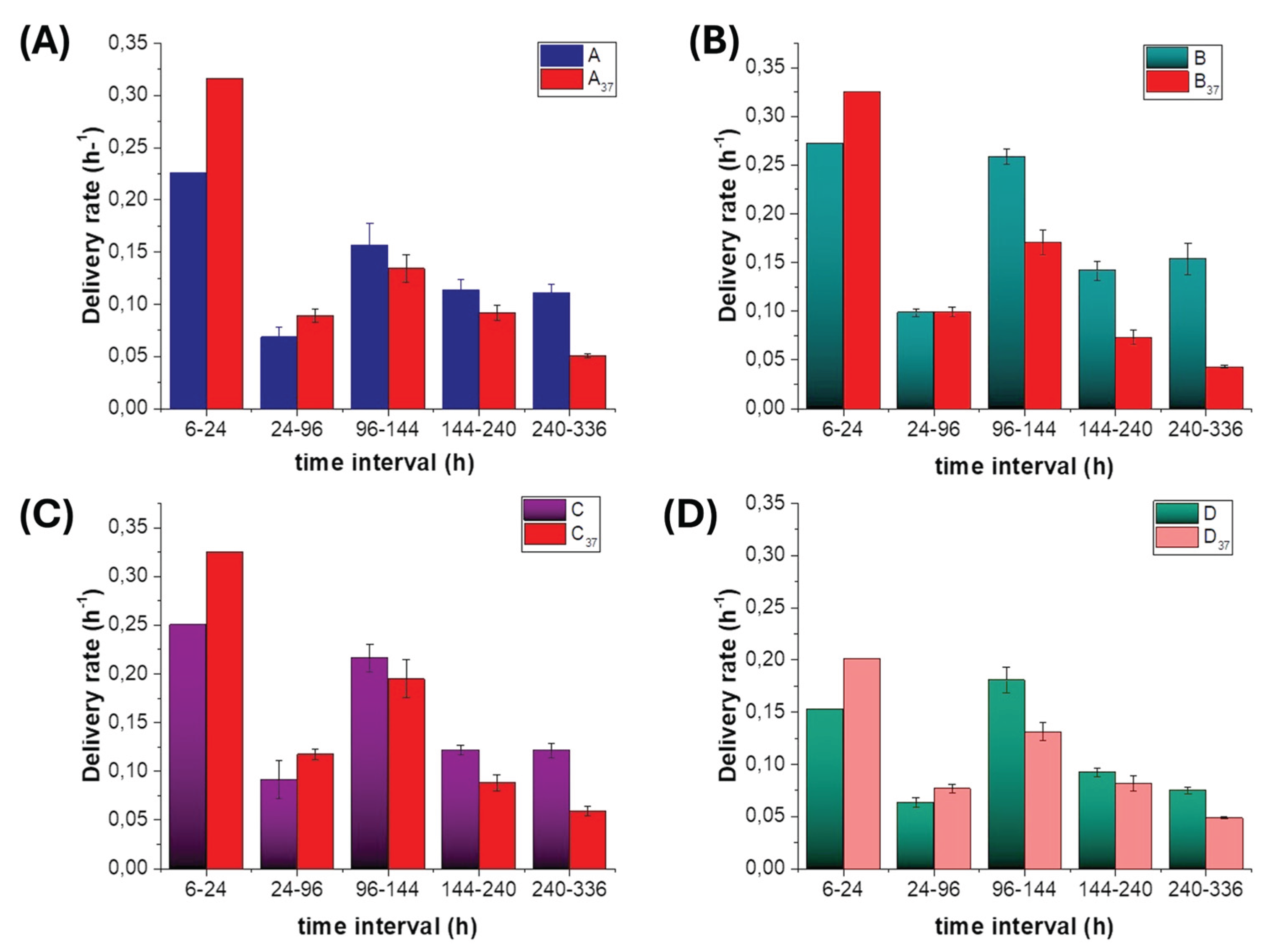
3.5.3. Polyphenol Release Rates at Ambient and 37 °C Temperatures.

In both datasets (TA and T37), we also examined instantaneous release rates, obtained as the slope of the cumulative curves over time intervals defined by the inflexion points of the multimodal profiles (Figure 13). At TA, all four matrices showed higher peak release rates than at T37, with MatB and MatC clearly dominating in the mid interval and MatD remaining rate-limited at every stage. At T37, the early (burst-window) rates were only slightly reduced or even enhanced for MatA and MatC, but mid- and late-interval rates dropped markedly for MatB and MatD, consistent with depot densification and pore tightening.
These rate trends are consistent with the integrated-area analysis: warming primarily compresses and attenuates the mid and late phases, particularly in MatB and MatD, whereas MatC remains the most productive and structurally robust system.

3.5.4. Key Parameters Controlling Polyphenol Release

The differences between matrices and temperatures can be rationalised in terms of a limited set of interdependent design variables.
  • Polymer phase and MAF/RAF microstructure: Both PHB and PCL are semicrystalline polyesters with crystalline lamellae embedded in an amorphous phase. Electrospinning produces oriented fibres in which the amorphous material can be separated conceptually into a mobile amorphous fraction (MAF), which hosts most of the diffusion pathways, and a rigid amorphous fraction (RAF) at crystal interfaces, which contributes more to mechanical stiffness than to transport. PHB typically crystallises more strongly and generates a larger RAF fraction, making it a slower, more gate-like carrier [86,87,93] . PCL, with a lower melting point and more mobile chains at both TA and T37, offers more continuous MAF pathways and behaves as a faster depot [118,119] . In the present architectures, PHB-rich regions therefore tend to set the overall permeability and late-phase quality, whereas PCL-rich depots largely control throughput in the burst and mid windows.
  • Bead evolution: shrinkage vs detachment: At T37, PCL-based beads evolved in two main ways: shrink-in-place densification (MatB and MatD) and adhesion-limited detachment (MatC). Densification reduces depot volume and mobile amorphous pathways, thereby eroding mid/late capacity, even if it shortens diffusion paths locally. Detachment instead removes some depots from the fibrous network, generating an early-release pulse while preserving the internal structure of the remaining HS-KL–GP-PP depots, thereby sustaining optimal late-phase release. PHB+GP-PP beads in MatA, by contrast, remained largely unchanged in size, acting as soft but increasingly shielded sources as the surrounding PHB matrix tightened
  • Fibre swelling and pore architecture: Fibres are not merely passive supports: they act as depots when loaded with GP-PP and, more importantly, as walls that define pore size, connectivity, and tortuosity. Swelling increases fibre diameter and reduces effective pore throats [120,121] , so a limited expansion can improve water access and wet the depots, whereas excessive swelling closes channels and throttles diffusion. In our system, co-electrospun PHB/PCL fibres in MatC swell least, PHB+HS-KL fibres in MatA and MatB show intermediate swelling, and GP-PP-only PHB/PCL fibres in MatD swell most, in line with their different GP-PP and HS-KL contents (Table 4), and the hydrophilic and H-bonding plasticising features of GP-PP. Thus, MatC preserves a relatively open, stable pore network that supports sustained mid/late release even at T37; MatA and MatB progressively tighten but retain usable pathways; and MatD evolves towards a highly swollen, tortuous mesh in which transport becomes access-limited and a large fraction of GP-PP remains trapped. Fibre swelling, therefore, acts as a second-level control on release, operating in parallel with bead densification/detachment and the chemical effects of HS-KL–GP-PP interactions.
  • Lignin as a physical and chemical stabiliser: HS-KL plays a dual stabilising role. Physically, it forms π–π and H-bond networks with PHB and PCL, which limit fibre swelling and promote secondary crystallisation in a controlled manner, thereby preserving the pore architecture—especially in MatC, where swelling is minimal even at T37. Chemically, when HS-KL and GP-PP are co-located (MatC), lignin provides binding sites and hydration shells that stabilise polyphenols and slow their desorption, yielding better-structured mid/late release and a more chemically rich late tail. Where HS-KL and GP-PP are segregated (MatB) or HS-KL is absent (MatD), depots are more prone to uncontrolled densification, and sensitive GP-PP classes are less protected.
  • Co-location vs segregation of HS-KL and GP-PP; GP-PP-only networks: The comparison between the matrices illustrates three regimes: i) Co-location (MatC) - HS-KL and GP-PP in the same PHB and PCL domains create genuine HS-KL-GP-PP depots: swelling is restricted, depots meter release, and labile species are better preserved. This configuration supports a broad burst-mid-late sequence that is relatively stable to temperature; ii) Segregation (MatA, MatB) - HS-KL in fibres and GP-PP in separate depots provide structural reinforcement and some gating, but do not directly co-stabilise the cargo. MatB exploits large PCL+GP-PP depots to maximise throughput at TA but loses much of this advantage at T37; MatA remains more conservative at both temperatures; iii) GP-PP-only networks (MatD) - Fibres and depots without HS-KL are strongly plasticised by GP-PP and water. Swelling and densification dominate, porosity collapses, and a substantial fraction of GP-PP remains trapped. This configuration performs poorly as a controlled-release system, even under high loading conditions.
Taken together, these observations point to a set of practical design rules for CRP-type materials based on PHB/PCL, lignin and polyphenols: combine a slower, more crystalline phase (PHB) with faster PCL depots; ensure at least one architecture in which HS-KL and GP-PP are co-located to create stabilised depots; limit GP-PP-only carrier phases; and tune bead size and adhesion so that depots contribute both to mid and late release without excessive densification or irreversible loss.

3.6. Integrated Mechanistic Interpretation

This section integrates the structural, wetting and release data to identify the main design rules governing polyphenol delivery from the four biohybrid matrices.

3.6.1. Early Wetting (10 min, TA ) Versus Long-Term Release (14 days, TA)

Bulleted Dynamic WCA/WDV tests at TA probe only the first few minutes of scaffold–water interaction under a sessile droplet. Under these conditions, MatA clearly stands out: its apparent WCA drops from ≈110–120° to ~75° and the WDV decreases by ~70%, whereas MatB–D show only a few degrees of WCA decrease and ~10% volume loss, values compatible with evaporation plus modest superficial hydration. Thus, at TA, the early wetting hierarchy is: MatA ≫ MatB ≈ MatC ≈ MatD.
This picture changes when the release is viewed over 14 days at TA. The total GP-PP released follows the order MatB > MatC > MatA > MatD, and the burst, mid, and late areas all follow the same ranking in absolute terms. t50 is longest for MatA and shortest for MatD (MatA > MatB > MatC > MatD). Hence, the scaffold that hydrates fastest at the surface (MatA) is not the most productive releaser, whereas a matrix with little early WCA change (MatB) dominates the long-term delivery at TA.
Mechanistically, this decoupling reflects the difference between local surface restructuring and bulk reorganisation of the 3D network: i) MatA combines PHB+HS-KL fibres with PHB+GP-PP beads. HS-KL and GP-PP are both accessible in the near-surface region, so the Cassie state collapses locally within minutes, producing strong WCA/WDV changes. However, PHB depots do not densify, GP-PP loading is moderate, and the PHB-only framework remains relatively restrictive; the result is a modest burst and intermediate mid/late release, despite the very reactive "skin". ii) MatB couples PHB+HS-KL fibres with large PCL+GP-PP beads. On the 10-min timescale, water mainly contacts hydrophobic PCL surfaces and a limited area of PHB+HS-KL fibres, so WCA and WDV barely change. Over hours-days, however, water gradually plasticises both PHB and PCL phases, without yet triggering strong bead densification at TA. Large PCL depots then deliver high burst, mid and late fluxes, making MatB the most productive system in all three phases at TA. iii) MatC is structurally tight at TA due to the co-location of HS-KL-GP-PP in both PHB and PCL fibres and PCL beads. Osmotic water uptake and swelling are reduced, so early wetting is conservative. Yet, once hydrated, multiple HS-KL-GP-PP depots in both phases provide well-metered pathways, yielding the second-highest total release and the largest fractional late contribution. iv) MatD contains GP-PP-only PHB and PCL fibres, as well as PCL beads. Even at TA, this configuration tends to swell and partially densify depots, trapping a relevant portion of the payload and limiting effective diffusion. As a result, MatD is the weakest releaser despite the highest nominal GP-PP loading.
In summary, 10-min WCA/WDV at TA reports how the outer skin hydrates and restructures, whereas 14-day TA release reflects how the entire fibre–bead network reorganises. A strongly “reactive” surface (MatA) does not guarantee the highest long-term release, and a seemingly inert surface (MatB) can still support the most productive burst/mid/late sequence once the bulk has hydrated.

3.6.2. Effect of Warming to 37 °C: How Temperature Reshapes Release

At T37, three processes act together: (i) water and solute mobility increase; (ii) polymer reorganisation accelerates (fibre swelling, secondary crystallisation, bead shrinkage or detachment); (iii) thermal sensitivity of GP-PP and HS-KL-GP-PP complexes becomes relevant. Under these conditions, the hierarchy of GP-PP release becomes: i) Total area: MatC > MatB > MatA > MatD; ii) Burst and mid: MatC ≥ MatB > MatA > MatD; iii) Late tail: MatC > MatA > MatD > MatB; t50: MatB < MatC < MatA < MatD.
Thus, MatC becomes the dominant releaser at 37 °C, MatB loses much of its advantage, MatA remains intermediate, and MatD stays the weakest despite its strong swelling.
These changes can be traced back to the different morphologies and HS-KL/GP-PP placements: i) MatA (PHB+HS-KL fibres, PHB+GP-PP beads): At T37, PHB+HS-KL fibres swell moderately (~32% increase in diameter), and PHB depots hydrate more rapidly. Faster diffusion enhances the burst area, but PHB ageing (MAF → RAF conversion, lamellar thickening) narrows pores and progressively suppresses mid and late flux. Overall, MatA becomes more front-loaded at 37 °C, with a conservative late tail and intermediate total release. ii) MatB (PHB+HS-KL fibres, large PCL+GP-PP beads): MatB is the most temperature-sensitive system. At T37, PHB+HS-KL fibres swell (+17%), and PCL beads shrink and densify (≈36% in area), reducing the accessible amorphous volume and cutting off late-diffusion pathways. The burst and mid remain appreciable, but the late tail is sharply reduced, and total release drops by more than one-third compared with TA. MatB thus shifts from the best TA performer to a matrix with fast t50 and a truncated tail under warm stress. iii) MatC (PHB/PCL fibres and PCL beads with HS-KL+GP-PP co-located): Co-location of HS-KL and GP-GP-PP in both polymer phases strongly limits fibre swelling (+4.8%) and favours bead detachment (≈22% total bead area) rather than shrink-in-place. At T37, this architecture responds by increasing burst and mid areas (due to faster hydration and partial release from labile or detached depots) while still preserving the highest total release and the strongest absolute late tail. HS-KL-GP-PP complexes continue to meter diffusion and stabilise labile classes, so MatC emerges as the most robust, well-structured releaser under warm conditions. iv) MatD (GP-PP-only PHB/PCL fibres and PCL beads): MatD experiences extreme fibre swelling (~+175% diameter) and bead densification (≈23% area) at T37, resulting in a highly swollen, partially collapsed network. Tortuosity and access limitations dominate; the burst remains the smallest, mid and late peaks are weak, and total release is the lowest at both TA and T37. Large structural changes, therefore, do not translate into effective delivery when no lignin is present to stabilise and meter the system.
Overall, the 37 °C test shows that the apparent advantage of higher temperature for diffusion is often offset by structural tightening and depot evolution. Only the HS-KL-GP-PP co-located architecture of MatC preserves a high total output and a useful late tail under warm stress.

3.6.3. Final Synthesis and Design Rules

Combining the TA and T37 results yields a coherent set of design rules: i) Short-term WCA/WDV at TA is mechanistic rather than predictive. It identifies scaffolds whose surface is intrinsically prone to rapid hydration and Cassie-state collapse (MatA), but it does not, by itself, predict long-term performance. The 14-day release profiles at TA and T37 are instead governed by bulk morphology, fibre swelling, bead evolution, and HS-KL-GP-PP localisation. ii) Polymer phase and morphology must be deliberately combined. PCL beads and bead-on-string domains act as high-capacity depots and dominate throughput (especially in MatB and MatC), whereas PHB, particularly when combined with HS-KL, provides structural rigidity and gating, thereby influencing the extent of that throughput and the behaviour of late tails. iii) HS-KL-GP-PP co-location is the most effective strategy. When HS-KL and GP-PP share the same PHB and PCL domains (MatC), HS-KL-GP-PP complexes reduce fibre swelling, stiffen the amorphous regions, stabilise labile polyphenols and support a structured burst-mid-late sequence that remains robust at T37. When HS-KL is restricted to fibres and GP-PP to separate depots (MatB, MatA), or when HS-KL is absent (MatD), temperature-induced densification and ageing are less buffered and late phases are structurally or chemically compromised. iv) Bead behaviour and fibre swelling act as coupled levers. In MatB and MatD, PCL beads shrink in place at T37, reducing depot volume and late capacity; in MatC, HS-KL-bearing beads are more prone to detachment, generating an early/mid pulse without fully sacrificing the late tail. In parallel, limited fibre swelling (MatC) preserves pore architecture and transport pathways, whereas extreme swelling (MatD) closes pores and traps GP-PP in a highly hydrated but poorly permeable network.
From a practical standpoint, these rules explain why MatB is the best option for maximum short- to mid-term mass delivery at TA, MatC is the most reliable and chemically “clean” releaser under both TA and warm conditions, MatA provides a conservative, self-braking profile, and MatD illustrates the limits of GP-PP-only carriers

3.7. Potential Applications of the Biohybrid Nanostructures

The release profiles recorded in this work (modest burst on day 1, a strong mid pulse around days 5-8, and a late tail up to days 10-14) resemble a two-week establishment programme rather than a season-long fertiliser curve. In Mediterranean systems, this window coincides with transplant shock, early root proliferation, and the onset of rapid vegetative growth - phases in which a polyphenol pulse can buffer oxidative stress, stabilise membranes, and “prime” the rhizosphere, thereby improving nutrient-use efficiency (NUE) rather than supplying nutrients directly.
Polyphenols are not nutrients, but they support nutrient uptake by reducing oxidative load, enhancing membrane integrity and modulating the soil-root interface (microbial signalling, Fe/P availability, organo–mineral interactions). The day-1 to day-14 multimodal pattern therefore aligns with known peaks in functional demand: immediate post-transplant stress (day 0-3), root initiation and early N/P uptake (day 3-7), and first fast vegetative growth (day 7-14), particularly under fluctuating moisture and episodic heat typical of Mediterranean springs and early summers.
On this basis, the matrices can be matched to crops and temperature regimes as follows (summarised in Table S6)
  • Ambient conditions (≈15-25 °C, irrigated or mild climates): i) MatB: best suited to fast, leafy crops (rocket, baby-leaf mixes, young brassicas) and short cycles, where a strong mass delivery over 1-2 weeks is desirable, and the late tail serves mainly to smooth the decline. ii) MatC: preferable for fruiting vegetables and perennial seedlings (tomato, pepper, aubergine, cucurbits, strawberry, vine/olive/citrus liners), where a well-metered, chemically "clean" late phase is advantageous for sustained antioxidant and signalling support. iii) MatA: conservative option when a gentle profile is required (e.g., sensitive seedlings, low-input systems), accepting a lower total release. iv) MatD: not recommended as a primary carrier due to its low effective release despite high loading.
  • Warm or stressed beds (surface soil‚ ≈32-37 °C; shallow Mediterranean soils in hot periods): i) MatCremains the first choice because it preserves the highest total release and late tail under thermal stress, making it suitable for summer transplants of Solanaceae and cucurbits, or for shallow-rooted perennials on hot aspects. ii) MatA can be used where only a modest, self-limiting pulse is desired under heat (e.g., to avoid excessive stimulation or where other inputs are high). iii) MatB becomes temperature-sensitive: it can still be exploited in cooler or irrigated beds but is less appropriate in persistently hot, shallow soils unless reformulated to reduce depot densification. iv) MatD should be avoided in hot conditions, as its pronounced swelling and poor control lead to weak, poorly metered release.
Illustrative applications in Mediterranean timing include: MatC patches at transplant for tomato, pepper and aubergine (field or tunnel), where the burst covers transplant shock, the mid peak overlaps root proliferation and first N/P ramp, and the late tail approaches early flowering; similar use for zucchini, melon and watermelon in warm beds; MatB at TA for rocket and baby-leaf crops to maximise early leaf expansion; MatC for autumn-planted strawberry runners and young vine/olive/citrus liners, where a two-week support phase assists rooting and establishment.

4. Conclusions

This work tested whether eco-friendly nanotechnological products composed of electrospun ± electrosprayed PHB/PCL biohybrid scaffolds loaded with agro-waste–derived lignin and polyphenols (from hazelnut shells and grape-pomace, respectively) could function as controlled-release polyphenol (CRP) systems for agricultural use. Four matrices were engineered by varying polymer phase (PHB vs PCL), Klason lignin presence and localisation, and the distribution of polyphenols (GP-PP) between fibres and bead-like depots. Morphology, early wetting and long-term release at TA and T37 were analysed using CRF-type criteria (burst amplitude, burst–mid–late structure, t50, temperature robustness and late-tail quality).
All matrices exhibited multimodal GP-PP release at TA, with three peaks grouped into burst, mid, and late phases over ~14 days, with modest initial bursts, which is favourable for avoiding transient phytotoxicity and better matching plant nutrient demand. At TA, the PHB/PCL composite MatB (HS-KL in PHB fibres, GP-PP in large PCL beads) showed the highest total release and the largest late tail; MatC (HS-KL and GP-PP co-located in both PHB and PCL fibres and in PCL beads) ranked second in total but provided a smoother, better metered profile and a chemically “richer” late fraction (flavonols and anthocyanins); MatA (PHB+HS-KL fibres and PHB+GP-PP particles, no HS-KL–GP-PP co-location) delivered an intermediate, more conservative profile; and MatD (GP-PP-only PHB/PCL fibres and beads, no HS-KL) released the smallest amount despite the highest nominal GP-PP loading, underscoring that GP-PP loading alone does not imply effective delivery.
When the temperature was raised to 37 °C, mimicking shallow Mediterranean soils during hot periods, all profiles became more compressed (earlier t50) and total and late release decreased, due to PHB ageing, PCL depot reorganisation and fibre swelling. Under these stressed conditions, MatB became the most temperature-sensitive, with strong losses in mid and late release; MatA showed a modestly increased burst but stronger mid/late gating; MatD suffered extreme swelling and depot densification with persistently weak release; in contrast, MatC remained structurally and functionally the most robust, retaining the highest total GP-PP release and the strongest late tail at T37, enriched in flavonols, stilbenes and HS-KL-stabilised anthocyanins, despite PCL bead detachment.
In agronomic terms, these findings suggest that at TA, MatB is suitable where a high two-week GP-PP dose is desired (e.g., fast-growing or short-cycle crops in cooler or irrigated systems), whereas MatC is preferable when a slightly lower total amount but a better controlled, sustained and chemically valuable late phase is required. Under warm conditions around T37, MatC clearly outperforms the other formulations in both quantity and quality of late release, MatA behaves as a conservative, self-limiting scaffold, and MatD remains too weak for practical use.
Beyond ranking individual formulations, the study yields general design rules for CRP materials from agro-industrial residues. (i) Polymer phase and morphology must be co-designed: PCL beads act as high-throughput depots, whereas PHB, especially with HS-KL, provides structural gating and supports late-phase quality. (ii) Co-location of lignin and polyphenols in the same domains is crucial for true metering and chemical stabilisation: when HS-KL is restricted to fibres (MatB) or absent (MatD), late tails are structurally or chemically compromised; when HS-KL and GP-PP share both PHB and PCL phases (MatC), HS-KL–GP-PP complexes limit swelling, stiffen the network and protect labile GP-PP classes. (iii) Bead–fibre adhesion is a useful tuning parameter: in MatC, partial detachment of HS-KL+GP-PP PCL beads contributes to a beneficial mid-time pulse at T37, but excessive loss would erode late capacity. Nevertheless, loss of GP-PP-loaded beads can provide an additional pathway for cargo release, ensuring further delivery in porous media. (iv) GP-PP-only fibres should not be the main carriers, as they swell excessively at elevated temperatures and collapse porosity, giving poor control (MatD).
Overall, this work shows that PHB/PCL electrospun ± electrosprayed biohybrid scaffolds incorporating lignin and polyphenols from agro-industrial waste can be rationally engineered to deliver CRF-like, temperature-responsive polyphenol release over agronomically relevant time windows. Among the architectures tested, the HS-KL–GP-PP co-located design of MatC emerges as a particularly promising platform for controlled delivery of antioxidant, signalling or biostimulant polyphenols in soils and rhizospheres, and the mechanistic understanding gained here - linking polymer phase, lignin placement, morphology and temperature to burst–mid–late behaviour - provides a transferable basis for future CRP systems, including those loaded with other bioactives and evaluated under field conditions.

Supplementary Materials

Supplementary Materials: The following supporting information can be downloaded at the website of this paper posted on Preprints.org. Table S1. List of comprehensive classes of nanomaterials, their general use, some specific applications and final products or processes, and mode of applications. Table S2. List of common polymer nanofibre types, their general uses, some specific applications with final products or processes, and mode of application. Table S3. Common constituent groups, components and main sources of agro-industrial waste originating from the processing of plant- or animal-derived materials. Table S4. List of main value-added products obtained from agro-industrial waste. Table S5. Some physicochemical properties of polyphenol classes and subclasses. Table S6. Matrix-by-matrix match between scaffold type (MatA–MatD), temperature scenario (ambient vs warm soils), crop category and management context (e.g., transplant vs direct sowing, protected vs open field), preferred application mode and depth, and the rationale for each choice in terms of burst/mid/late release characteristics. Figure S1. Identification of polyphenol components in the grape pomace extract through UV/VIS spectra at the respective absorbance wavelengths of aliquots resolved by HPLC: A) phenolic acids and flavan-3-ols at 280 nm, B) anthocyanins at 520 nm, C) stilbenes at 307 nm, and D) flavonols (quercetins) at 365 nm. Figure S2. Simulated UV/VIS absorbance spectra, in the range 200 nm-800 nm, of some polyphenol classes present in typical plant extracts (flavonoids, phenolic acids, stilbenes, hydrolysable tannins, and lignans), highlighting the absorbance peaks characteristics of each class and of the resulting combination (Total) (not quantitative). Figure S3. Simulated UV/VIS absorbance spectra, in the range 200 nm-800 nm, of polyphenols in plant extracts exhibiting the dependence on the solvent: water (pH 7.0 buffer) (blue), methanol (orange), ethanol (green), and DMSO (red) (A). Simulated UV/VIS absorbance spectra, in the range 200 nm-800 nm, of polyphenols in plant extracts displaying the dependence on pH: pH 1.0 (blue), 3.5 (orange), 7.4 (green), 9.0 (red), and 11.0 (violet) (B). Simulated UV/VIS absorbance spectra, in the range 150 nm-300 nm, of the various organic components typically present in the grape-pomace extracts upon polyphenol extraction (C). Simulated UV/VIS absorbance spectra, in the range 200 nm-800 nm, of the various polyphenols identified in this study in the grape-pomace (GP) extract and the relative assignment of the absorbance peaks as follows: anthocyanins, flavan-3-ols, flavonols (quercetin family), phenolic acids, and stilbenes (D). The UV/VIS absorbance spectrum in D considers the solvent used for the GP extract (methanol:water, 80:20 v/v) and the phosphate buffer (pH 7.4), where the extract absorbance was measured. Peaks modelled as Gaussians; total is normalised to a maximum of 1 for display (i.e. considering only the compounds measured and not including any unquantified polyphenols). A, B, and C are not quantitative. D refers to the total amount measured (Table 2) and accounts for the fact that the visible anthocyanin peak fades with increasing pH, becoming progressively colourless. The spectra here shown are specifically addressed to the 250–600 nm interval to emphasize diagnostic polyphenol bands; deep-UV absorption (<230 nm), which is typically dominated by strong aromatic π→π* transitions and background contributions, is here omitted. Figure S4. Schematic of typical CRF release rate profiles with burst, mid and late tail phases as typical of monomodal, bimodal and multimodal CRF.

Author Contributions

Conceptualization, A.M.; methodology, S.S., A.M., G.A., A.B., S.A.S., G.S., G.D.C. C.R. and P.P.; formal analysis, G.D.C. and C.R.; investigation, A.M., S.S..; resources, A.M., G.S., G.D.C., G.A., A.B.; data curation, F.D.C., S.S., A.M., G.A., A.B., S.A.S., G.S., G.D.C. and C.R.; writing—original draft preparation, F.D.C., S.S.; writing—review and editing, F.D.C., A.M.; visualization, F.D.C., S.S., A.M., G.A., A.B., S.A.S., G.S., G.D.C. and C.R; supervision, F.D.C., A.M.; funding acquisition, A.M. All authors have read and agreed to the published version of the manuscript.

Funding

Please add: This research was funded by the National Research Council (CNR), through the Project “TERRE”—Strategic Research Projects@CNR 2020–2022, No. AdC.202204-5.

Institutional Review Board Statement

Not applicable.

Data Availability Statement

The data presented in this study are available from the corresponding author upon request. The data are currently stored in IRIS, the institutional open-access repository of the National Research Council of Italy (CNR).

Acknowledgements

We acknowledge the support of A. Capocecera of IIA-CNR for his technical collaboration in software development and use, K. Stephensen of Brigham Young University-Utah (US) for her technical support during her undergraduate international stage, and S. Berti (IIA-CNR) for his administrative support. During the preparation of this manuscript, the authors used ChatGpt, 5.2 (by Open AI) for generating Figure 1, Figure S2, Figure S3, Figure S4. Additionally, they used Grammarly Premium (by Grammarly Inc.) for English language and style revision. The authors have reviewed and edited the output and take full responsibility for the content of this publication.

Conflicts of Interest

The authors declare no conflicts of interest.

Abbreviations

The following abbreviations are used in this manuscript:
PHB Poly-3-hydroxybutyric acid
PCL Polycaprolactone
CRF Controlled-release fertilisers
SRF Slow-release fertilisers
CRP Controlled-release polyphenols
HS Hazelnut-shells
HS-KL Hazelnut-shell Klason lignin (acid-insoluble fraction by Klason method); not Kraft lignin
GP Grape-pomace
GP-PP Grape-pomace polyphenols
(FE-)SEM Field-emission Scanning electron microscopy
FTIR-ATR Fourier Transform Infrared-Attenuated Total Reflectance
UV–VIS Ultraviolet-Visible radiation
WCA Water contact angle
WDV Water droplet volume
RAF Rigid amorphous fraction
MAF Mobile amorphous fraction
HBA Hydroxybenzoic acid

References

  1. Prado-Acebo, I.; Cubero-Cardoso, J.; Lu-Chau, T.A.; Eibes, G. Integral Multi-Valorization of Agro-Industrial Wastes: A Review. Waste Manag. 2024, 183, 42–52. [Google Scholar] [CrossRef] [PubMed]
  2. Kour, R.; Singh, S.; Sharma, H.B.; Naik, T.S.S.K.; Shehata, N.; N, P.; Ali, W.; Kapoor, D.; Dhanjal, D.S.; Singh, J.; et al. Persistence and Remote Sensing of Agri-Food Wastes in the Environment: Current State and Perspectives. Chemosphere 2023, 317, 137822. [Google Scholar] [CrossRef] [PubMed]
  3. Mondéjar-López, M.; García-Simarro, M.P.; Navarro-Simarro, P.; Gómez-Gómez, L.; Ahrazem, O.; Niza, E. A Review on the Encapsulation of “Eco-Friendly” Compounds in Natural Polymer-Based Nanoparticles as next Generation Nano-Agrochemicals for Sustainable Agriculture and Crop Management. Int. J. Biol. Macromol. 2024, 280, 136030. [Google Scholar] [CrossRef]
  4. Hazarika, A.; Yadav, M.; Yadav, D.K.; Yadav, H.S. An Overview of the Role of Nanoparticles in Sustainable Agriculture. Biocatal. Agric. Biotechnol. 2022, 43, 102399. [Google Scholar] [CrossRef]
  5. Joudeh, N.; Linke, D. Nanoparticle Classification, Physicochemical Properties, Characterization, and Applications: A Comprehensive Review for Biologists. J. Nanobiotechnology 2022, 20, 262. [Google Scholar] [CrossRef]
  6. Shekhawat, D.; Vauth, M.; Pezoldt, J. Size Dependent Properties of Reactive Materials. Inorganics 2022, 10, 56. [Google Scholar] [CrossRef]
  7. El-Kady, M.M.; Ansari, I.; Arora, C.; Rai, N.; Soni, S.; Verma, D.K.; Singh, P.; Mahmoud, A.E.D. Nanomaterials: A Comprehensive Review of Applications, Toxicity, Impact, and Fate to Environment. J. Mol. Liq. 2023, 370, 121046. [Google Scholar] [CrossRef]
  8. Belay, T.; Worku, L.A.; Bachheti, R.K.; Bachheti, A.; Husen, A. Advances in Smart Nanomaterials and Their Applications; 2023; pp. 1–21. [Google Scholar] [CrossRef]
  9. Ding, B.; Yu, J.; Wang, X. Electrospinning: Nanofabrication and Applications, 1st ed.; Ding, *!!! REPLACE !!!*, Yu, *!!! REPLACE !!!*, Bin, *!!! REPLACE !!!*, Wang, *!!! REPLACE !!!*, Jianyong, *!!! REPLACE !!!*, Xianfeng, *!!! REPLACE !!!*, Eds.; Elsevier Inc.; ISBN 9780323512701.
  10. Asmatulu, R.; Khan, W.S. Synthesis and Applications of Electrospun Nanofibers; Elsevier Inc.: Amsterdam, Netherlands, 2019; ISBN 978-0-12-813914-1. [Google Scholar]
  11. Keirouz, A.; Wang, Z.; Reddy, V.S.; Nagy, Z.K.; Vass, P.; Buzgo, M.; Ramakrishna, S.; Radacsi, N. The History of Electrospinning: Past, Present, and Future Developments. Adv. Mater. Technol. 2023, 8. [Google Scholar] [CrossRef]
  12. Cleeton, C.; Keirouz, A.; Chen, X.; Radacsi, N. Electrospun Nanofibers for Drug Delivery and Biosensing. Acs Biomater Sci Eng 2019, 5, 4183–4205. [Google Scholar] [CrossRef]
  13. Abdulhussain, R.; Adebisi, A.; Conway, B.R.; Asare-Addo, K. Electrospun Nanofibers: Exploring Process Parameters, Polymer Selection, and Recent Applications in Pharmaceuticals and Drug Delivery. J. Drug Deliv. Sci. Technol. 2023, 90, 105156. [Google Scholar] [CrossRef]
  14. Vatanpour, V.; Kose-Mutlu, B.; Koyuncu, I. Electrospraying Technique in Fabrication of Separation Membranes: A Review. Desalination 2022, 533, 115765. [Google Scholar] [CrossRef]
  15. Huang, S.; Mansouri, J.; Le-Clech, P.; Leslie, G.; Tang, C.Y.; Fane, A.G. A Comprehensive Review of Electrospray Technique for Membrane Development: Current Status, Challenges, and Opportunities. J. Membr. Sci. 2022, 646, 120248. [Google Scholar] [CrossRef]
  16. Jayaprakash, P.; Maudhuit, A.; Gaiani, C.; Desobry, S. Encapsulation of Bioactive Compounds Using Competitive Emerging Techniques: Electrospraying, Nano Spray Drying, and Electrostatic Spray Drying. J. Food Eng. 2023, 339, 111260. [Google Scholar] [CrossRef]
  17. Tang, J.; Wu, C.; Chen, S.; Qiao, Z.; Borovskikh, P.; Shchegolkov, A.; Chen, L.; Wei, D.; Sun, J.; Fan, H. Combining Electrospinning and Electrospraying to Prepare a Biomimetic Neural Scaffold with Synergistic Cues of Topography and Electrotransduction. ACS Appl. Bio Mater. 2020, 3, 5148–5159. [Google Scholar] [CrossRef]
  18. Soheili, S.; Dolatyar, B.; Adabi, M.R.; Lotfollahi, D.; Shahrousvand, M.; Zahedi, P.; Seyedjafari, E.; Mohammadi-Rovshandeh, J. Fabrication of Fiber-Particle Structures by Electrospinning/Electrospray Combination as an Intrinsic Antioxidant and Oxygen-Releasing Wound Dressing. J. Mater. Chem. B 2024, 12, 9074–9097. [Google Scholar] [CrossRef]
  19. He, M.-K.; He, Y.-L.; Li, Z.-Q.; Zhao, L.-N.; Zhang, S.-Q.; Liu, H.-M.; Qin, Z. Structural Characterization of Lignin and Lignin-Carbohydrate Complex (LCC) of Sesame Hull. Int. J. Biol. Macromol. 2022, 209, 258–267. [Google Scholar] [CrossRef] [PubMed]
  20. García-Fuentevilla, L.; Rubio-Valle, J.F.; Martín-Sampedro, R.; Valencia, C.; Eugenio, M.E.; Ibarra, D. Different Kraft Lignin Sources for Electrospun Nanostructures Production: Influence of Chemical Structure and Composition. Int. J. Biol. Macromol. 2022, 214, 554–567. [Google Scholar] [CrossRef]
  21. Luzi, F.; Yang, W.; Ma, P.; Torre, L.; Puglia, D. Lignin-Based Materials for Biomedical Applications; 2021; pp. 291–326. [Google Scholar] [CrossRef]
  22. Luzi, F.; Torre, L.; Puglia, D. Micro and Nanolignin in Aqueous Dispersions and Polymers; 2022; pp. 293–324. [Google Scholar] [CrossRef]
  23. Budnyak, T.M.; Slabon, A.; Sipponen, M.H. Lignin–Inorganic Interfaces: Chemistry and Applications from Adsorbents to Catalysts and Energy Storage Materials. ChemSusChem 2020, 13, 4344–4355. [Google Scholar] [CrossRef]
  24. Mateo, S.; Fabbrizi, G.; Moya, A.J. Lignin from Plant-Based Agro-Industrial Biowastes: From Extraction to Sustainable Applications. Polymers 2025, 17, 952. [Google Scholar] [CrossRef] [PubMed]
  25. Ariyanta, H.A.; Sari, F.P.; Sohail, A.; Restu, W.K.; Septiyanti, M.; Aryana, N.; Fatriasari, W.; Kumar, A. Current Roles of Lignin for the Agroindustry: Applications, Challenges, and Opportunities. 2023, 240, 124523. [Google Scholar] [CrossRef] [PubMed]
  26. Gaspar, R.; Fardim, P. Lignin-Based Materials for Emerging Advanced Applications. Curr. Opin. Green Sustain. Chem. 2023, 41, 100834. [Google Scholar] [CrossRef]
  27. Shorey, R.; Salaghi, A.; Fatehi, P.; Mekonnen, T.H. Valorization of Lignin for Advanced Material Applications: A Review. RSC Sustain. 2024, 2, 804–831. [Google Scholar] [CrossRef]
  28. Yang, G.; Gong, Z.; Luo, X.; Chen, L.; Shuai, L. Bonding Wood with Uncondensed Lignins as Adhesives. Nature 2023, 621, 511–515. [Google Scholar] [CrossRef]
  29. Zagoskina, N.V.; Zubova, M.Y.; Nechaeva, T.L.; Kazantseva, V.V.; Goncharuk, E.A.; Katanskaya, V.M.; Baranova, E.N.; Aksenova, M.A. Polyphenols in Plants: Structure, Biosynthesis, Abiotic Stress Regulation, and Practical Applications (Review). Int. J. Mol. Sci. 2023, 24, 13874. [Google Scholar] [CrossRef] [PubMed]
  30. Koudoufio, M.; Desjardins, Y.; Feldman, F.; Spahis, S.; Delvin, E.; Levy, E. Insight into Polyphenol and Gut Microbiota Crosstalk: Are Their Metabolites the Key to Understand Protective Effects against Metabolic Disorders? Antioxidants 2020, 9, 982. [Google Scholar] [CrossRef]
  31. Panzella, L.; Napolitano, A. Condensed Tannins, a Viable Solution To Meet the Need for Sustainable and Effective Multifunctionality in Food Packaging: Structure, Sources, and Properties. J. Agric. Food Chem. 2022, 70, 751–758. [Google Scholar] [CrossRef] [PubMed]
  32. Gourlay, G.; Hawkins, B.J.; Albert, A.; Schnitzler, J.; Constabel, C.P. Condensed Tannins as Antioxidants That Protect Poplar against Oxidative Stress from Drought and UV-B. Plant, Cell Environ. 2022, 45, 362–377. [Google Scholar] [CrossRef]
  33. Liu, Y.; Shi, Y.; Zhang, M.; Han, F.; Liao, W.; Duan, X. Natural Polyphenols for Drug Delivery and Tissue Engineering Construction: A Review. Eur. J. Med. Chem. 2024, 266, 116141. [Google Scholar] [CrossRef] [PubMed]
  34. Wang, H.; Wang, C.; Zou, Y.; Hu, J.; Li, Y.; Cheng, Y. Natural Polyphenols in Drug Delivery Systems: Current Status and Future Challenges. Giant 2020, 3, 100022. [Google Scholar] [CrossRef]
  35. Raju, N.N.; Sankaranarayanan, M.; Bharathiraja, B. Production of Polyhydroxybutyrate (PHB), a Biodegradable Polymer from Seaweed Biomass Using Novel Bacterial Isolates. J. Mol. Struct. 2024, 1303, 137511. [Google Scholar] [CrossRef]
  36. Balasubramanian, V.K.; Chellapandi, R.; Balakrishnan, M.; Murugan, K.; Kennedy, J.P.K.J.; Murugan, S.; Khumalo, M.V.; Sarangi, P.K.; Chou, J.-Y.; Muthuramalingam, J.B. Biosynthesis of Bioplastic Polyhydroxybutyrate (PHB) from Microbes Isolated from Paddy/Sugarcane Fields and Fabrication of Biodegradable Thin Film. Process Saf. Environ. Prot. 2024, 187, 1178–1188. [Google Scholar] [CrossRef]
  37. Price, S.; Kuzhiumparambil, U.; Pernice, M.; Ralph, P.J. Cyanobacterial Polyhydroxybutyrate for Sustainable Bioplastic Production: Critical Review and Perspectives. J. Environ. Chem. Eng. 2020, 8, 104007. [Google Scholar] [CrossRef]
  38. Mandragutti, T.; Jarso, T.S.; Godi, S.; Begum, S.S.; K, B. Physicochemical Characterization of Polyhydroxybutyrate (PHB) Produced by the Rare Halophile Brachybacterium Paraconglomeratum MTCC 13074. Microb. Cell Factories 2024, 23, 59. [Google Scholar] [CrossRef]
  39. Rathna, R.P.; Kishore, S.N.; Kulandhaivel, M. Statistical Design-Driven Optimization of Polyhydroxy-Butyrate (PHB) Production Using Sugarcane Bagasse by Brevibacterium Sp. (PP989436) Strain. J. Polym. Environ. 2025, 33, 910–927. [Google Scholar] [CrossRef]
  40. Rathna, R.P.; Kulandhaivel, M. Sustainable Synthesis of Biopolymer Polyhydroxybutyrate (PHB) from Agro-Residue by Brevibacterium Casei with Emphasis on Degradation Analysis. J. Pure Appl. Microbiol. 2024, 18, 347–366. [Google Scholar] [CrossRef]
  41. Kotcharat, P.; Chuysinuan, P.; Thanyacharoen, T.; Techasakul, S.; Ummartyotin, S. Development of Bacterial Cellulose and Polycaprolactone (PCL) Based Composite for Medical Material. Sustain. Chem. Pharm. 2021, 20, 100404. [Google Scholar] [CrossRef]
  42. Spizzirri, U.G.; Aiello, F.; Carullo, G.; Facente, A.; Restuccia, D. Nanotechnologies: An Innovative Tool to Release Natural Extracts with Antimicrobial Properties. Pharmaceutics 2021, 13, 230. [Google Scholar] [CrossRef] [PubMed]
  43. Bang, J.; Kim, J.-H.; Park, S.-W.; Kim, J.; Jung, M.; Jung, S.; Kim, J.-C.; Choi, I.-G.; Kwak, H.W. Effect of Chemically Modified Lignin Addition on the Physicochemical Properties of PCL Nanofibers. Int. J. Biol. Macromol. 2023, 240, 124330. [Google Scholar] [CrossRef] [PubMed]
  44. TAPPI Acid-Insoluble Lignin in Wood and Pulp. In 2002-2003 TAPPI Test Methods; Tappi Press: Atlanta, GA, USA, 2002.
  45. Agustin-Salazar, S.; Cerruti, P.; Medina-Juárez, L.Á.; Scarinzi, G.; Malinconico, M.; Soto-Valdez, H.; Gamez-Meza, N. Lignin and Holocellulose from Pecan Nutshell as Reinforcing Fillers in Poly (Lactic Acid) Biocomposites. Int. J. Biol. Macromol. 2018, 115, 727–736. [Google Scholar] [CrossRef] [PubMed]
  46. Ritchey, J.G.; Waterhouse, A.L. A Standard Red Wine: Monomeric Phenolic Analysis of Commercial Cabernet Sauvignon Wines. Am. J. Enol. Vitic. 1999, 50, 91–100. [Google Scholar] [CrossRef]
  47. Torrent, J.; Pfeiffer, M.; Ibañez, J.J. Encyclopedia of Soils in the Environment (Second Edition). Pedology 2023, 319–331. [Google Scholar] [CrossRef]
  48. Marzaioli, R.; D’Ascoli, R.; Pascale, R.A.D.; Rutigliano, F.A. Soil Quality in a Mediterranean Area of Southern Italy as Related to Different Land Use Types. Appl. Soil Ecol. 2010, 44, 205–212. [Google Scholar] [CrossRef]
  49. Sadh, P.K.; Duhan, S.; Duhan, J.S. Agro-Industrial Wastes and Their Utilization Using Solid State Fermentation: A Review. Bioresour Bioprocess 2018, 5, 1. [Google Scholar] [CrossRef]
  50. Commission, E. Bioeconomy Research and Innovation. Available online: https://research-and-innovation.ec.europa.eu/research-area/environment/bioeconomy_en (accessed on 16 January 2026).
  51. WasteManaged Agricultural Waste Guide 2025. Available online: https://www.wastemanaged.co.uk/our-news/agriculture/agricultural-waste-guide/?utm_source=chatgpt.com (accessed on 18 January 2026).
  52. Šelo, G.; Planinić, M.; Tišma, M.; Tomas, S.; Komlenić, D.K.; Bucić-Kojić, A. A Comprehensive Review on Valorization of Agro-Food Industrial Residues by Solid-State Fermentation. Foods 2021, 10, 927. [Google Scholar] [CrossRef] [PubMed]
  53. Lee, H.V.; Hamid, S.B.A.; Zain, S.K. Conversion of Lignocellulosic Biomass to Nanocellulose: Structure and Chemical Process. Sci. World J. 2014, 2014, 631013. [Google Scholar] [CrossRef]
  54. Srivastava, K.; Chaudhary, K.; Adil, M.; Rajora, A. Exploring the Potential of Lignin Nanoparticles: Synthesis, Applications, and Future Directions. Polym. Bull. 2025, 82, 6277–6306. [Google Scholar] [CrossRef]
  55. Singh, S.K.; Singh, A.; Mishra, S. Electrospun Nanofibers, Fabrication, Functionalisation and Applications. Springer Ser. Polym. Compos. Mater. 2021, 171–197. [Google Scholar] [CrossRef]
  56. Adam, A.A.; Dennis, J.O.; Al-Hadeethi, Y.; Mkawi, E.M.; Abdulkadir, B.A.; Usman, F.; Hassan, Y.M.; Wadi, I.A.; Sani, M. State of the Art and New Directions on Electrospun Lignin/Cellulose Nanofibers for Supercapacitor Application: A Systematic Literature Review. Polymers 2020, 12, 2884. [Google Scholar] [CrossRef] [PubMed]
  57. Kai, D.; Jiang, S.; Low, Z.W.; Loh, X.J. Engineering Highly Stretchable Lignin-Based Electrospun Nanofibers for Potential Biomedical Applications. J. Mater. Chem. B 2015, 3, 6194–6204. [Google Scholar] [CrossRef]
  58. Nainggolan, G.; Gea, S.; Marpongahtun; Harahap, M.; Dellyansyah; Situmorang, S.A. Promoting Electrospun Lignin/PEO Nanofiber for High-Performance CO Filtration. J. Nat. Fibers 2023, 20, 2160402. [Google Scholar] [CrossRef]
  59. Chutturi, M.; Kelkar, B.U.; Yadav, S.M.; Wibowo, E.S.; Bhuyar, P.; Naik, B.P.; Sinha, A.; Lee, S.H. Exploring Nanolignin as a Sustainable Biomacromolecule in Polymer Composites: Synthesis, Characterization, and Applications: A Review. Int. J. Biol. Macromol. 2025, 304, 140881. [Google Scholar] [CrossRef]
  60. Camargos, C.H.M.; Yang, L.; Jackson, J.C.; Tanganini, I.C.; Francisco, K.R.; Ceccato-Antonini, S.R.; Rezende, C.A.; Faria, A.F. Lignin and Nanolignin: Next-Generation Sustainable Materials for Water Treatment. ACS Appl. Bio Mater. 2025, 8, 2632–2673. [Google Scholar] [CrossRef]
  61. Saini, N.; Anmol, A.; Kumar, S.; Wani, A.W.; Bakshi, M.; Dhiman, Z. Exploring Phenolic Compounds as Natural Stress Alleviators in Plants- a Comprehensive Review. Physiol. Mol. Plant Pathol. 2024, 133, 102383. [Google Scholar] [CrossRef]
  62. Patil, J.R.; Mhatre, K.J.; Yadav, K.; Yadav, L.S.; Srivastava, S.; Nikalje, G.C. Flavonoids in Plant-Environment Interactions and Stress Responses. Discov. Plants 2024, 1, 68. [Google Scholar] [CrossRef]
  63. Kumar, G.A.; Kumar, S.; Bhardwaj, R.; Swapnil, P.; Meena, M.; Seth, C.S.; Yadav, A. Recent Advancements in Multifaceted Roles of Flavonoids in Plant–Rhizomicrobiome Interactions. Front. Plant Sci. 2024, 14, 1297706. [Google Scholar] [CrossRef]
  64. Hättenschwiler, S.; Vitousek, P.M.; Hättenschwiler, S.; Vitousek, P.M. The Role of Polyphenols in Terrestrial Ecosystem Nutrient Cycling. Trends Ecol. Evol. 2000, 15, 238–243. [Google Scholar] [CrossRef] [PubMed]
  65. Min, K.; Freeman, C.; Kang, H.; Choi, S.-U. The Regulation by Phenolic Compounds of Soil Organic Matter Dynamics under a Changing Environment. Biomed Res Int 2015, 2015, 825098. [Google Scholar] [CrossRef]
  66. Shah, A.; Smith, D.L. Flavonoids in Agriculture: Chemistry and Roles in, Biotic and Abiotic Stress Responses, and Microbial Associations. Agronomy 2020, 10, 1209. [Google Scholar] [CrossRef]
  67. Mekapogu, M.; Vasamsetti, B.M.K.; Kwon, O.-K.; Ahn, M.-S.; Lim, S.-H.; Jung, J.-A. Anthocyanins in Floral Colors: Biosynthesis and Regulation in Chrysanthemum Flowers. Int. J. Mol. Sci. 2020, 21, 6537. [Google Scholar] [CrossRef]
  68. Buondonno, A.; Capra, G.F.; Coppola, E.; Dazzi, C.; Grilli, E.; Odierna, P.; Rubino, M.; Vacca, S. Aspects of Soil Phenolic Matter (SPM): An Explorative Investigation in Agricultural, Agroforestry, and Wood Ecosystems. Geoderma 2014, 213, 235–244. [Google Scholar] [CrossRef]
  69. Cortés-Ferré, H.E.; Arredondo-Ochoa, T.; Gaytán-Martínez, M. Polysaccharides-Polyphenolic Interactions: Formation, Functionality and Applications. Trends Food Sci. Technol. 2025, 163, 105117. [Google Scholar] [CrossRef]
  70. Guo, Y.; Sun, Q.; Wu, F.; Dai, Y.; Chen, X. Polyphenol-Containing Nanoparticles: Synthesis, Properties, and Therapeutic Delivery. Adv. Mater. 2021, 33, e2007356. [Google Scholar] [CrossRef]
  71. Xu, W.; Lin, Z.; Pan, S.; Chen, J.; Wang, T.; Cortez-Jugo, C.; Caruso, F. Direct Assembly of Metal-Phenolic Network Nanoparticles for Biomedical Applications. Angew. Chem. Int. Ed. 2023, 62, e202312925. [Google Scholar] [CrossRef] [PubMed]
  72. Huo, K.; Liu, W.; Shou, Z.; Wang, H.; Liu, H.; Chen, Y.; Zan, X.; Wang, Q.; Li, N. Modulating the Interactions of Peptide-Polyphenol for Supramolecular Assembly Coatings with Controllable Kinetics and Multifunctionalities. Adv. Sci. 2025, 12, 2412194. [Google Scholar] [CrossRef] [PubMed]
  73. Kaeswurm, J.A.H.; Scharinger, A.; Teipel, J.; Buchweitz, M. Absorption Coefficients of Phenolic Structures in Different Solvents Routinely Used for Experiments. Molecules 2021, 26, 4656. [Google Scholar] [CrossRef]
  74. Velho, P.; Rebelo, C.S.; Macedo, E.A. Extraction of Gallic Acid and Ferulic Acid for Application in Hair Supplements. Molecules 2023, 28, 2369. [Google Scholar] [CrossRef]
  75. Uivarasan, A.; Lukinac, J.; Jukić, M.; Šelo, G.; Peter, A.; Nicula, C.; Cozmuta, A.M.; Cozmuta, L.M. Characterization of Polyphenol Composition and Starch and Protein Structure in Brown Rice Flour, Black Rice Flour and Their Mixtures. Foods 2024, 13, 1592. [Google Scholar] [CrossRef] [PubMed]
  76. Favaro, L.; Balcão, V.; Rocha, L.; Silva, E.; Jr, J.O.; Vila, M.; Tubino, M. Physicochemical Characterization of a Crude Anthocyanin Extract from the Fruits of Jussara (Euterpe Edulis Martius): Potential for Food and Pharmaceutical Applications. J. Braz. Chem. Soc. 2018. [Google Scholar] [CrossRef]
  77. Boulet, J. -C.; Ducasse, M. -A.; Cheynier, V. Ultraviolet Spectroscopy Study of Phenolic Substances and Other Major Compounds in Red Wines: Relationship between Astringency and the Concentration of Phenolic Substances. Aust. J. Grape Wine Res. 2017, 23, 193–199. [Google Scholar] [CrossRef]
  78. Grasel, F. dos S.; Ferrão, M.F.; Wolf, C.R. Ultraviolet Spectroscopy and Chemometrics for the Identification of Vegetable Tannins. Ind. Crop. Prod. 2016, 91, 279–285. [Google Scholar] [CrossRef]
  79. Nakamura, K.; Shirato, M.; Ikai, H.; Kanno, T.; Sasaki, K.; Kohno, M.; Niwano, Y. Photo-Irradiation of Proanthocyanidin as a New Disinfection Technique via Reactive Oxygen Species Formation. PLoS ONE 2013, 8, e60053. [Google Scholar] [CrossRef]
  80. Chua, L.S.; Thong, H.Y.; Soo, J. Effect of pH on the Extraction and Stability of Anthocyanins from Jaboticaba Berries. 2024, 5, 100835. [Google Scholar] [CrossRef]
  81. Okello, A.; Owuor, B.O.; Namukobe, J.; Okello, D.; Mwabora, J. Influence of the pH of Anthocyanins on the Efficiency of Dye Sensitized Solar Cells. 2022, 8, e09921. [Google Scholar] [CrossRef]
  82. Ku, C.S.; Mun, S.P. Characterization of Proanthocyanidin in Hot Water Extract Isolated from Pinus Radiata Bark. Wood Sci. Technol. 2007, 41, 235. [Google Scholar] [CrossRef]
  83. Espina, A.; Sanchez-Cortes, S.; Jurašeková, Z. Vibrational Study (Raman, SERS, and IR) of Plant Gallnut Polyphenols Related to the Fabrication of Iron Gall Inks. Molecules 2022, 27, 279. [Google Scholar] [CrossRef]
  84. Argenziano, R.; Moccia, F.; Esposito, R.; D’Errico, G.; Panzella, L.; Napolitano, A. Recovery of Lignins with Potent Antioxidant Properties from Shells of Edible Nuts by a Green Ball Milling/Deep Eutectic Solvent (DES)-Based Protocol. Antioxidants 2022, 11, 1860. [Google Scholar] [CrossRef] [PubMed]
  85. Li, Z.; Chen, Z.; Chen, H.; Chen, K.; Tao, W.; Ouyang, X.; Mei, L.; Zeng, X. Polyphenol-Based Hydrogels: Pyramid Evolution from Crosslinked Structures to Biomedical Applications and the Reverse Design. Bioact. Mater. 2022, 17, 49–70. [Google Scholar] [CrossRef]
  86. Lugoloobi, I.; Li, X.; Zhang, Y.; Mao, Z.; Wang, B.; Sui, X.; Feng, X. Fabrication of Lignin/Poly(3-Hydroxybutyrate) Nanocomposites with Enhanced Properties via a Pickering Emulsion Approach. Int. J. Biol. Macromol. 2020, 165, 3078–3087. [Google Scholar] [CrossRef]
  87. Weihua, K.; He, Y.; Asakawa, N.; Inoue, Y. Effect of Lignin Particles as a Nucleating Agent on Crystallization of Poly(3-hydroxybutyrate). J. Appl. Polym. Sci. 2004, 94, 2466–2474. [Google Scholar] [CrossRef]
  88. Vollrath, A.; Kretzer, C.; Beringer-Siemers, B.; Shkodra, B.; Czaplewska, J.A.; Bandelli, D.; Stumpf, S.; Hoeppener, S.; Weber, C.; Werz, O.; et al. Effect of Crystallinity on the Properties of Polycaprolactone Nanoparticles Containing the Dual FLAP/mPEGS-1 Inhibitor BRP-187. Polymers 2021, 13, 2557. [Google Scholar] [CrossRef] [PubMed]
  89. Govil, S.; Long, N.V.D.; Escribà-Gelonch, M.; Hessel, V. Controlled-Release Fertiliser: Recent Developments and Perspectives. Ind. Crop. Prod. 2024, 219, 119160. [Google Scholar] [CrossRef]
  90. Mansouri, H.; Said, H.A.; Noukrati, H.; Oukarroum, A.; youcef, H.B.; Perreault, F. Advances in Controlled Release Fertilizers: Cost-Effective Coating Techniques and Smart Stimuli-Responsive Hydrogels. Adv. Sustain. Syst. 2023, 7. [Google Scholar] [CrossRef]
  91. Lawrencia, D.; Wong, S.K.; Low, D.Y.S.; Goh, B.H.; Goh, J.K.; Ruktanonchai, U.R.; Soottitantawat, A.; Lee, L.H.; Tang, S.Y. Controlled Release Fertilizers: A Review on Coating Materials and Mechanism of Release. Plants 2021, 10, 1–26. [Google Scholar] [CrossRef]
  92. Swify, S.; Mažeika, R.; Baltrusaitis, J.; Drapanauskaitė, D.; Barčauskaitė, K. Review: Modified Urea Fertilizers and Their Effects on Improving Nitrogen Use Efficiency (NUE). Sustainability 2023, 16, 188. [Google Scholar] [CrossRef]
  93. Stephens, J.S.; Chase, D.B.; Rabolt, J.F. Effect of the Electrospinning Process on Polymer Crystallization Chain Conformation in Nylon-6 and Nylon-12. Macromolecules 2004, 37, 877–881. [Google Scholar] [CrossRef]
  94. Lizundia, E.; Sipponen, M.H.; Greca, L.G.; Balakshin, M.; Tardy, B.L.; Rojas, O.J.; Puglia, D. Multifunctional Lignin-Based Nanocomposites and Nanohybrids. Green Chem 2021, 23, 6698–6760. [Google Scholar] [CrossRef] [PubMed]
  95. Meenu, M.; Pujari, A.K.; Kirar, S.; Mansi; Thakur, A.; Garg, M.; Bhaumik, J. Development of Bionanocomposite Packaging Films Based on Lignin Nanoencapsulated Anthocyanins Extracted from Agro-Waste for Enhancing the Post-Harvest Shelf Life of Tomatoes. Sustain. Food Technol. 2025, 3, 414–424. [Google Scholar] [CrossRef]
  96. Lv, X.; Mu, J.; Wang, W.; Liu, Y.; Lu, X.; Sun, J.; Wang, J.; Ma, Q. Effects and Mechanism of Natural Phenolic Acids/Fatty Acids on Copigmentation of Purple Sweet Potato Anthocyanins. Curr. Res. Food Sci. 2022, 5, 1243–1250. [Google Scholar] [CrossRef] [PubMed]
  97. Pajer, N.; Cestari, C.; Argyropoulos, D.S.; Crestini, C. From Lignin Self Assembly to Nanoparticles Nucleation and Growth: A Critical Perspective. npj Mater. Sustain. 2024, 2, 31. [Google Scholar] [CrossRef]
  98. Zhang, Z.; Yan, Y. The Effect of Surface Roughness on Sessile Droplet Evaporation Dynamics of Silica Nanofluid. Int. J. Heat Mass Transf. 2024, 234, 126156. [Google Scholar] [CrossRef]
  99. Bormashenko, E. Progress in Understanding Wetting Transitions on Rough Surfaces. Adv. Colloid Interface Sci. 2015, 222, 92–103. [Google Scholar] [CrossRef]
  100. Chen, X.; Ma, R.; Li, J.; Hao, C.; Guo, W.; Luk, B.L.; Li, S.C.; Yao, S.; Wang, Z. Evaporation of Droplets on Superhydrophobic Surfaces: Surface Roughness and Small Droplet Size Effects. Phys. Rev. Lett. 2012, 109, 116101. [Google Scholar] [CrossRef]
  101. Bico, J.; Thiele, U.; Quéré, D. Wetting of Textured Surfaces. Colloids Surf. A: Physicochem. Eng. Asp. 2002, 206, 41–46. [Google Scholar] [CrossRef]
  102. Brutin, D.; Starov, V. Recent Advances in Droplet Wetting and Evaporation. Chem. Soc. Rev. 2017, 47, 558–585. [Google Scholar] [CrossRef]
  103. Liu, X.; Liu, L.; Yang, Y.; Liu, B.; Duan, R. Evaporation Characteristics of Sessile Droplets on Flat Hydrophobic Surfaces in Non-Boiling Regime. Int. Commun. Heat Mass Transf. 2023, 142, 106614. [Google Scholar] [CrossRef]
  104. McHale, G.; Newton, M.I.; Shirtcliffe, N.J. Dynamic Wetting and Spreading and the Role of Topography. J. Phys.: Condens. Matter 2009, 21, 464122. [Google Scholar] [CrossRef]
  105. Subramani, M.; Balakrishnan, P. Nano-Enabled Phosphorus Fertilizers: Mechanisms, Applications, and Environmental Implications – A Critical Review. Soil Tillage Res. 2026, 257, 106959. [Google Scholar] [CrossRef]
  106. Ma, X.; Chen, J.; Yang, Y.; Su, X.; Zhang, S.; Gao, B.; Li, Y.C. Siloxane and Polyether Dual Modification Improves Hydrophobicity and Interpenetrating Polymer Network of Bio-Polymer for Coated Fertilizers with Enhanced Slow Release Characteristics. Chem. Eng. J. 2018, 350, 1125–1134. [Google Scholar] [CrossRef]
  107. Sanford, R.A.; Chee-Sanford, J.C.; Yang, W.H. Diurnal Temperature Variation in Surface Soils: An Underappreciated Control on Microbial Processes. Front. Microbiol. 2024, 15, 1423984. [Google Scholar] [CrossRef]
  108. Chen, H.; Huang, S.; Quan, C.; Chen, Z.; Xu, M.; Wei, F.; Tang, D. Effects of Different Colors of Plastic-Film Mulching on Soil Temperature, Yield, and Metabolites in Platostoma Palustre. Sci. Rep. 2024, 14, 5110. [Google Scholar] [CrossRef]
  109. Chicco, J.M.; Mandrone, G.; Vacha, D. Effects of Wildfire on Soils: Field Studies and Modelling on Induced Underground Temperature Variations. Front. Earth Sci. 2023, 11, 1307569. [Google Scholar] [CrossRef]
  110. Cheng, Q.; Zhang, M.; Jin, H.; Ren, Y. Spatiotemporal Variation Characteristics of Hourly Soil Temperature in Different Layers in the Low-Latitude Plateau of China. Front. Environ. Sci. 2022, 10, 1091985. [Google Scholar] [CrossRef]
  111. Hillel, D. Environmental Soil Physics; 1998; pp. 309–339. [Google Scholar] [CrossRef]
  112. SinghGill, M.; Gill, P.; Pal, R.; Singh, N. Mulching Effects on Soil Temperature and Yield of Pear [Pyrus Pyrifoila (Burm.) Nakai] in Humid Subtropical Climate of Punjab. 2022, 73, 941–948. [Google Scholar] [CrossRef]
  113. Ramakrishna, A.; Tam, H.M.; Wani, S.P.; Long, T.D. Effect of Mulch on Soil Temperature, Moisture, Weed Infestation and Yield of Groundnut in Northern Vietnam. 2006, 95, 115–125. [Google Scholar] [CrossRef]
  114. Calderisi, G.; Salaris, E.; Cogoni, D.; Rossetti, I.; Murtas, F.; Fenu, G. Relationship Between Post-Fire Vegetation Recovery and Soil Temperature in the Mediterranean Forest. Fire 2025, 8, 91. [Google Scholar] [CrossRef]
  115. Lozano-Parra, J.; Pulido, M.; Lozano-Fondón, C.; Schnabel, S. How Do Soil Moisture and Vegetation Covers Influence Soil Temperature in Drylands of Mediterranean Regions? Water 2018, 10, 1747. [Google Scholar] [CrossRef]
  116. Delgado-Capel, M.J.; Egea-Cariñanos, P.; Cariñanos, P. Assessing the Relationship between Land Surface Temperature and Composition Elements of Urban Green Spaces during Heat Waves Episodes in Mediterranean Cities. Forests 2024, 15, 463. [Google Scholar] [CrossRef]
  117. Costa, J.M.; Egipto, R.; Aguiar, F.C.; Marques, P.; Nogales, A.; Madeira, M. The Role of Soil Temperature in Mediterranean Vineyards in a Climate Change Context. Front. Plant Sci. 2023, 14, 1145137. [Google Scholar] [CrossRef]
  118. Serra, R.S. i; Kyritsis, A.; Ivirico, J.L.E.; Ribelles, J.L.G.; Pissis, P.; Salmerón-Sánchez, M. Molecular Mobility in Biodegradable Poly( -Caprolactone)/Poly(Hydroxyethyl Acrylate) Networks. Eur. Phys. J. E 2011, 34, 37. [Google Scholar] [CrossRef]
  119. Flamini, M.D.; Lima, T.; Corkum, K.; Alvarez, N.J.; Beachley, V. Annealing Post-Drawn Polycaprolactone (PCL) Nanofibers Optimizes Crystallinity and Molecular Alignment and Enhances Mechanical Properties and Drug Release Profiles. Mater. Adv. 2022, 3, 3303–3315. [Google Scholar] [CrossRef]
  120. Ko, S.W.; Lee, J.Y.; Lee, J.; Son, B.C.; Jang, S.R.; Aguilar, L.E.; Oh, Y.M.; Park, C.H.; Kim, C.S. Analysis of Drug Release Behavior Utilizing the Swelling Characteristics of Cellulosic Nanofibers. Polymers 2019, 11, 1376. [Google Scholar] [CrossRef] [PubMed]
  121. Xu, F.; Sheardown, H.; Hoare, T. Reactive Electrospinning of Degradable Poly(Oligoethylene Glycol Methacrylate)-Based Nanofibrous Hydrogel Networks. Chem. Commun. 2015, 52, 1451–1454. [Google Scholar] [CrossRef] [PubMed]
Figure 1. A) Classification of main polyphenols. B) Major applications of polyphenols. C) Principal mechanisms involved in interactions between polyphenols, lignin and carrier polymers.
Preprints 198420 g001
Figure 2. Steps of hazelnut shell processing from harvesting (a) to waste formation upon outer shell (HS) cracking (b), to lignin extraction from HS (HS-KL: Hazelnut-shell Klason lignin) (c), and finally to its powder upon vacuum drying (d).
Preprints 198420 g002
Figure 3. UV/VIS absorbance spectra, in the range 195 nm-700 nm, of the polyphenolic extract from grape pomace, depicting two characteristic peaks: Peak 1 (207.5 nm) and Peak 2 (278.5 nm) (A). UV/VIS absorbance spectra, in the range 195 nm-700 nm, of lignin extracted from hazelnut shells (B). The inset in A shows an example of how the peak areas were calculated for quantitative analysis.
Preprints 198420 g003
Figure 4. FTIR-ATR spectrum of purified Klason lignin (acid-insoluble fraction) from hazelnut shells (HS-KL).
Preprints 198420 g004
Figure 5. Schematic of nutrient release dynamics for different type of fertilisers: Conventional/Raw fertilisers; Slow-Release Fertilisers (SRF); Controlled-Release Fertilisers (CRF). Nutrient release rate (A); Cumulative nutrient release (%).
Preprints 198420 g005
Figure 6. Comparison of nanostructured scaffolds MatA, MatB, MatC, and MatD before (A,C,E,G) and after (B,D,F,H) 14-day soaking in the 0.11 M phosphate buffer (pH 7.4) at 37 °C as observed by Stereomicroscopy.
Preprints 198420 g006
Figure 7. Comparison of nanostructured scaffolds MatA, MatB, MatC, and MatD before (A,C,E,G) and after (B,D,F,H) 14-day soaking in the 0.11 M phosphate buffer (pH 7.4) at 37 °C as observed by Optical Microscopy.
Preprints 198420 g007
Figure 8. Comparison of pristine nanostructured scaffolds MatA, MatB, MatC, and MatD as observed by Scanning Electron Microscopy at low (MatA, MatB, MatC and MatD: 5k×) (inset) and high (MatA, MatB, and MatD: 15k×; MatC: 20k×) magnifications.
Preprints 198420 g008
Figure 9. Comparison of nanostructured scaffolds MatA, MatB, MatC, and MatD before (A,C,E,G) and after (B,D,F,H) 14-day soaking in the 0.11 M phosphate buffer (pH 7.4) at 37 °C as observed by Scanning Electron Microscopy (10k×).
Preprints 198420 g009
Figure 10. Time-dependence of water contact angle (A) and water droplet volume variation (B) for scaffolds MatA, MatB, MatC, and MatD, illustrating their different wetting and absorption behaviours over a 600 s (10 min) period.
Preprints 198420 g010
Figure 11. Normalised polyphenol release as a function of time for each scaffold at ambient temperature (A) and 37°C (C). Normalised cumulative release of polyphenols over time from the various matrices at ambient temperature (B) and 37°C (D).
Preprints 198420 g011
Figure 12. The day-by-day contribution of the various matrices along the 14-day incubation period calculated as the percentage of the UV-VIS absorbance of the incubation solutions of each matrix per day relative to the sum of the UV-VIS absorbance of all the fabrics on the same day, at both TA and T37.
Preprints 198420 g012
Figure 13. Normalised polyphenol release rates from each scaffold (Mats A to D) calculated at different incubation period intervals at ambient temperature and at 37 °C (e.g. MatA vs MatA37).
Preprints 198420 g013
Table 1. Description of the electrospun ± electrosprayed scaffolds in terms of composition, weight percentage of components in solution, deposition mode (electrospinning/electrospraying) and processing conditions.
Scaffolds Description Ratio (w/w) Rate and Voltage* ES/ESP Polymers
(%Tot w/w)
Lignin
(%Tot w/w)
Polyphenols
(%Tot w/w)
MetA Combination of: -4.5 KV; (1) 7.3 KV; (2) 8.3 KV
-Sol.1) PHB+HS-KL 1:0.033 500 µL/h ES 64.77% PHB 2.22%
-Sol.2) PHB+GP-PP 1:0.088 1600 µL/h ESP 30.23% PHB 2.78%
MetB Combination of: -10 KV; (1) 8.5 KV; (7) 14 KV
-Sol.1) PHB+HS-KL 1:0.033 500 µL/h ES 61.75% PHB 2.02%
-Sol.7) PCL+GP-PP 1:0.075 1600 µL/h ESP 33.70% PCL 2.53%
MetC Combination of: -3.5 KV; (3) 7.3 KV; (4) 9.3 KV
-Sol.3) PHB+HS-KL+GP-PP 1:0.065:0.058 750 µL/h ES 41.36% PHB 2.71% 2.42%
-Sol.4) PCL+HS-KL+GP-PP 1:0.056:0.050 750 µL/h ES 48.38% PCL 2.71% 2.42%
MetD Combination of: -5.5 KV; (5) 7.6 KV; (6) 10.3 KV
-Sol.5) PHB+GP-PP 1:0.058 750 µL/h ES 43.73% PHB 0% 2.56%
-Sol.6) PCL+GP-PP 1:0.050 750 µL/h ES 51.15% PCL 0% 2.56%
Note *In the voltage conditions, the first value corresponds to the negative potential applied to the collector, while the second and third values refer to the positive voltage applied to the needle during electrospinning and electrospraying.
Table 2. Polyphenol composition of the extract obtained from grape pomace waste.
Polyphenol classes Compounds Content (mg mL-1) Percent of total Percent within class
Anthocyanins Total 141.28 30.2
Malvidin-3-O-glucoside 40.88 8.7 28.9
Pelunidin-3-O-glucoside 36.27 7.7 25.7
Cyanidin-3-O-glucoside 32.68 7.0 23.1
Delphinidin-3-O-glucoside 31.45 6.7 22.3
Flavan-3-ols Total 94.38 20.2
Catechins 33.18 7.1 35.2
Procyanidin dimer B3 31.67 6.8 33.6
Procyanidin dimer B1 29.53 6.3 31.3
Flavonols (quercetins) Total 116.61 24.9
Quercetin 62.3 13.3 53.4
Quercetin-3-O-glucoside 49.31 10.5 42.3
Quercetin-3-O-rhamnoside 5.0 1.1 4.3
Phenolic acids Total 53.98 11.5
Hydroxybenzoic acids 35.57 7.6 65.9
Gallic acid 18.41 3.9 34.1
Stilbenes Resveratrol 62.12 13.3 100.0
Table 4. Morphological characterisation of fibres and particles comprising the bio-based nanohybrid scaffolds before and after 14-day soaking at 37°C in 0.11 M phosphate buffer (pH 7.4) based on Scanning Electron Microscopy (SEM) observations.
Scaffolds Fibre diameterp(µm) Fibre diameters(µm) Fibre diameter variation (%) Particle roundnessp Particle roundnesss Particle roundness variation (%)
MatA 1.03±0.63 1.36±0.46 32.3% 0.75±0.10 0.80±0.10 6.4%
MatB 1.21±0.34 1.42±0.31 17.0% 0.82±0.10 0.82±0.09 0%
MatC 0.23±0.06 0.24±0.06 5.1% 0.83±0.08 0.88±0.07 5.3%
MatD 0.28±0.07 0.76±0.18 174.4% 0.84±0.09 0.78±0.13 -6.9%
Scaffolds Particlep area(µm2) Particles area(µm2) Particle area variation (%) Particlep areaTot(µm2) Particles areaTot(µm2) Particle AreaTot variation(%)
MatA 1.03±0.43 1.05±0.34 1.3% 51.7 53.4 3.4%
MatB 7.31±2.77 4.70±2.09 -35.7% 365.7 235.2 -35.7%
MatC 0.81±0.47 0.81±0.41 0.5% 39.5 30.8 -22.1%
MatD 2.83±0.96 2.18±1.07 -22.8% 141.4 111.4 -22.5%
Notes p = pristine scaffolds
s = scaffolds upon soaking
Table 5. Matrix-by-matrix peak areas by GP-PP release profile regions, total areas, and t50 absolute values and percentage differences as a function of temperature (ambient and 37 °C temperatures). Numbers in brackets are the percentages of variation of the values at T37 relative to those at TA.
Ambient (TA) peak areas and t50
Matrix Burstregion Midregion Late tailregion Totalarea Latefraction t50 (h)
MatA 9.43 17.53 14.40 41.36 0,35 148
MatB 13.25 23.67 20.19 57.10 0,35 144
MatC 11.51 19.34 18.51 49.35 0,38 142
MatD 7.25 15.92 11.66 34.83 0,33 140
37 °C (T37) peak areas and t50
Matrix Burstregion Midregion Late tailregion Totalarea Late fraction t50 (h)
MatA 11.81 16.27 8.14 36.21 0,22 118
MatB 12.60 17.59 6.77 36.96 0,18 103
MatC 12.97 19.79 9.76 42.52 0,23 114
MatD 7.51 15.21 7.64 30.36 0,25 125
Δpeak areas (absolute and percentage changes)
Matrix ΔBurstregion ΔMidregion ΔLateregion ΔTotalarea ΔLate fraction ∆ t50 (h)
MatA +2.38 (+25.3%) −1.27 (-7.2%) −6.26 (-43.5%) −5.14 (-12.4%) −0.12 (-34.5%) −29.84 (-20.1%)
MatB −0.65 (-4.9%) −6.08 (-25.7%) −13.41 (-66.5%) −20.14 (-35.3%) −0.17 (-48.1%) −40.50 (-28.2%)
MatC +1.47 (+12.8) +0.45 (+2.4%) −8.75 (-47.3%) −6.83 (-13.8%) −0.15 (-40.0%) −28.00 (-19.7%)
MatD +0.26 (+3.5%) −0.71 (-4.4%) −4.02 (-34%) −4.47 (-12.8%) −0.08 (-23.9%) −14.88 (-10.7%)
Causes of variations
Notes Rises at 37 °C for MatA and MatC (faster hydration/solubility; in MatC also weaker bead–fibre adhesion), roughly flat/slightly down for MatB, small uptick for MatD Largest drop in MatB (PCL bead shrinkage + narrowed pores); MatC is slightly up due to the detached-bead pulse; MatA/MatD down modestly All down at 37 °C; the biggest fall is MatB , then MatC, MatA, MatD All down at 37 °C; the biggest fall is MatB, then MatC, MatA, MatD Earlier at 37 °C for every matrix (largest shift in MatB, meaning whatever can leave tends to do so before tightening/ageing fully develops. Earlier at 37 °C for every matrix (largest shift in MatB, meaning whatever can leave tends to do so before tightening/ageing fully develops.
Disclaimer/Publisher’s Note: The statements, opinions and data contained in all publications are solely those of the individual author(s) and contributor(s) and not of MDPI and/or the editor(s). MDPI and/or the editor(s) disclaim responsibility for any injury to people or property resulting from any ideas, methods, instructions or products referred to in the content.
Copyright: This open access article is published under a Creative Commons CC BY 4.0 license, which permit the free download, distribution, and reuse, provided that the author and preprint are cited in any reuse.
Prerpints.org logo

Preprints.org is a free preprint server supported by MDPI in Basel, Switzerland.

Subscribe

Disclaimer

Terms of Use

Privacy Policy

Privacy Settings

© 2026 MDPI (Basel, Switzerland) unless otherwise stated