Submitted:
09 February 2026
Posted:
11 February 2026
You are already at the latest version
Abstract
This paper presents the design, modeling, and numerical validation of a compact artificial magnetic conductor (AMC)–backed flexible UHF RFID tag antenna intended for on-body biomedical and wearable sensing applications. Human tissue proximity typically causes severe detuning, radiation efficiency degradation, and increased specific absorption rate (SAR) for conventional RFID tag antennas. To address these limitations, a miniaturized AMC metasurface based on a modified Jerusalem-cross geometry with meandered and interdigitated features is developed on a high-permittivity biocompatible substrate using CST Studio Software. Full-wave simulations demonstrate that the proposed design, with an ultra-compact footprint of 0.0246 λ2 (32.12 mm × 64.24 mm), functions as an effective shielding element, significantly enhancing the tag antenna gain and reading range by an order of magnitude compared to conventional on-body tags, while simultaneously reducing backward radiation and SAR. The antenna demonstrates robust platform tolerance and excellent isolation from the human body, ensuring high reliability. Fabricated on a thin, flexible, biocompatible, silicon-doped dielectric substrate, this device also functions as an epidermal antenna for on-skin health parameter sampling. This research paves the way for advanced, non-invasive wearable medical devices with superior performance.
Keywords:
UHF-RFID system
; AMC metasurface
; flexible antennas
; on-body applications
; biomedical applications
1. Introduction
The rapid digitization of healthcare has catalyzed a paradigm shift toward personalized medicine, centered on wearable biomedical devices that enable continuous, non-invasive health monitoring and diagnostics [1,2]. These innovations have brought new design challenges for wearable, implantable, and biocompatible systems (acting as the interface between the human body and the digital world) that rely on electromagnetic (EM) wave propagation to gather data about a person’s emotional, behavioral, environmental, and physical states, ultimately enhancing overall well-being [3,4]. As these devices evolve at the intersection of materials science, wireless communication, electromagnetics, mechanics, and electronics, there is an urgent need for radiators that are not only high-performing but also mechanically conformable and electromagnetically robust against the complex loading of human tissue [1,3,4].
These smart wearable devices blend seamlessly into everyday clothing and accessories, paving the way for innovative applications for health and wellness monitoring. Wireless data collection is essential, and passive radio frequency identification (RFID) technology in the Ultra-High Frequency (UHF) band undoubtedly stands out as the ideal solution owing to its proven reliability and capability to harvest energy from the reader signals [5,6] and seamless integration with the Internet of Things [6].
RFID offers a battery-less architecture, harvesting energy directly from the interrogator’s signal, which facilitates long-term maintenance-free operation [5,6].RFID systems operate on the principle of electromagnetic backscattering, employing tiny Integrated Circuit (IC) transponders that seamlessly integrate with low-profile, flexible wearable devices, capable of providing a read range of more than 10 meters in the Ultra-High Frequency (UHF) range [7]. Additionally, modern RFID Integrated Circuits (ICs) have transitioned from simple ID transponders to sophisticated sensing nodes, capable of interfacing directly with epidermal sensors to monitor temperature, humidity, or biochemical markers], facilitating health monitoring by easily acquiring epidermal data through RFID tag-skin interaction without the need for additional complex signal-conditioning circuitry [2,8,9,10].
Despite these advantages, designing on-body RFID antennas presents a fundamental "antenna-in-environment" problem. The human body is a high-permittivity, lossy, and dispersive medium. When a standard antenna is placed in close proximity to the skin, the high dielectric constant of the underlying tissue causes severe impedance detuning, while the tissue conductivity leads to significant power absorption, resulting in the deterioration of antenna efficiency, read range, and thereby raising safety concerns [10,11,12,13,14]. This absorption is quantified by the Specific Absorption Rate (SAR), which must be minimized to comply with stringent safety standards (e.g., FCC/ICNIRP). Furthermore, the dielectric properties of the "platform" are not constant; they depend on the antenna operational frequency range and also vary significantly across different anatomical regions—such as the high-water-content muscle of the thigh versus the low-permittivity adipose tissue of the chest—and vary between individual patients [15,16,17,18,19]. This variability often necessitates a different antenna design for every body part, which is impractical for mass-market healthcare solutions.
To overcome these challenges and attain better on-body performance, conventional mitigation strategies have employed planar inverted-F antennas (PIFAs), microstrip patch antennas, and aperture antenna designs, relying on a metallic ground plane to isolate the radiator from the body [20,21,22,23]. However, at UHF frequencies, these structures typically require thick dielectric substrates or air gaps to maintain isolation and ensure sufficient bandwidth and radiation efficiency, leading to bulky, rigid profiles that hinder wearer comfort.
Traditional UHF RFID tag antennas employ a meandered dipole configuration, which provides long current paths, leading to miniaturized and low-cost operation [24,25,26,27]. However, these meandered tags experience destructive interference when placed on conductive platforms, such as the human body, as reflected signals combine out of phase with incident signals, reducing the read range [28]. Alternatively, patch antennas with full ground planes isolate underlying conductive objects, but suffer from a large size and low radiation efficiency [9,29].
One effective solution, offering a good height-efficiency trade-off is to integrate the designed tag antenna with Artificial Magnetic Conductors, which have been proposed as high-impedance surfaces (HIS) [30,31,32,33]. Unlike a Perfect Electric Conductor (PEC) that reflects waves with a 180° phase shift—leading to destructive interference for low-profile antennas—an AMC acts as a "magnetic mirror." These artificially engineered surfaces reflect therefore incident waves constructively with a near-zero phase shift within their resonance band, allowing the antenna to be placed extremely close to the surface without deteriorating its behaviour [34,35,36,37]. In addition, the AMC structure also helps to suppress the back-lobe radiation by providing isolation from the underlying human body platform. This arrangement significantly enhances the antenna radiation gain and efficiency, reduces SAR (to comply with FCC standards), and improves overall on-body performance [34,35,36,37].
This intrinsic isolation property of AMCs is effectively utilized while integrating it with an arbitrary antenna, provided the antenna has smaller dimensions. The supported antenna may be of a wire type or a planar design. For optimum performance, appropriate spacing between the AMC and the antenna is often required. This gap can be conveniently filled through suitable dielectric support or lightweight materials, such as foam.
The gain enhancement due to isolation resulting from employing the AMC structure also depends upon the layout of the antenna. For instance, the Planar Inverted-F Antenna (PIFA) [38,39] with existing ground planes exhibits a gain improvement of a few decibels when integrated with AMC structures. Conversely, generic tag structures such as printed monopoles [40] and Yagi-Uda designs [41] exhibit a gain improvement exceeding 10 dB, highlighting the significant role of AMC structure support in delivering adequate radiation performance and realized gain under typical operating conditions.
Current literature has explored various AMC structures for on-body applications [32,33,34,35,36,42,43,44,45,46,47,48], aiming to achieve single-band [32,36,37,47,48] and multiband behavior [38,39,40,41,45,49,50]. However, most reported designs suffer from three critical shortcomings:
- excessive footprints relative to the radiator size,
- performance degradation when subjected to mechanical bending (conformality),
- a lack of platform tolerance.
Many existing tags are optimized for a specific phantom and fail when moved to a body part with different dielectric properties [42,43,44,45,46,49,50], showing a weak permittivity invariance. Furthermore, miniaturizing AMC cells for the lower UHF RFID spectrum remains a significant design bottleneck due to the long wavelengths involved [24,25,28,29,47,48,51].
This research addresses these gaps by proposing a methodology for a novel, ultra-thin (2.23 mm) AMC-integrated RFID tag antenna for on-body biomedical applications. The proposed structure utilizes a thin (2 mm) silicon-doped flexible substrate for the AMC, and a 200 µm PET substrate for the tag, while all the metallic traces have been implemented using a 10 µm-thick silver-ink with conductivity 106 S/m. The resulting 2.23 mm profile is significantly thinner than traditional AMC-backed designs, yet it provides high-gain and low-SAR operation, and the structure is fully planar, flexible, conformable, low cost, and can be used as epidermal antenna. The structure has been designed using CST Microwave Studio 2025, a general-purpose software for the 3D electromagnetic simulation of microwave components. CST is a well-assessed and established electromagnetic software for more than 20 years, and its results can be considered equivalent to experimental data, as reported in the open literature for a wide range of applications (see, for example, [49,50,51,52,53,54,55,56,57,58]). Hence, we rely on CST results for assessing the performance of the proposed structure, ensuring the results align with established benchmarks for on-body epidermal applications.
Table 1 compares the proposed work with recent high-impact literature focusing on AMC-backed wearable antennas.
A critical analysis of the table above reveals several key advantages of the proposed methodology over existing state-of-the-art designs:
Height and Profile (The "Zero-Gap" Advantage): Most existing designs (e.g., [42,43,44]) rely on significant air gaps or thick foam spacers ranging from 3 mm to 10 mm to achieve constructive reflection and decoupling. In contrast, the proposed structure achieves a record-low profile of 2.23 mm with zero air gap, directly integrating the tag with the AMC substrate without sacrificing performance.
Radiation Efficiency and Gain Increment: The gain improvement of 13 dB reported in this work is among the highest in the literature for the UHF band. Many textile-based antennas ([43],[46]) show much lower increments, suggesting that their AMC structures are less efficient at suppressing back-lobe radiation into the lossy human body.
Electrical Compactness: With an electrical area of only 0.0246λ2, our antenna is significantly more compact than the majority of UWB and textile antennas (e.g.,[46] at 2.01 λ2). This miniaturization is achieved without the typical narrow-band limitations associated with compact UHF designs.
Mechanical and Biological Compatibility: Unlike rigid FR4-based designs ([45],[51]), our structure is fully flexible and conformable. Furthermore, whereas many designs ignore the impact of diverse phantoms, this work focuses on Robust Platform Tolerance, ensuring that the antenna does not require an air gap to maintain its resonance across different tissue types (fat, muscle, skin).Frequency Target: While many recent works focus on the 2.45 GHz or 5.8 GHz ISM bands ([42],[43],[44],[46])—where antenna dimensions are naturally smaller—this work tackles the more challenging 868 MHz UHF RFID band, delivering a compact and ultra-thin solution where wavelength-related size constraints are much more severe.
The performance of the proposed RFID tag was rigorously evaluated and compared under two distinct operating conditions: directly mounted on the human body and integrated with a custom-designed Artificial Magnetic Conductor (AMC) structure. The AMC layer serves as an electromagnetic shield, effectively isolating the tag from the high-loss dielectric environment of the wearer's body. Experimental results demonstrate a substantial enhancement in the tag antenna gain, yielding an increase of approximately 13 dB. This gain improvement—nearly an order of magnitude—significantly outperforms typical increments reported for similar wearable devices in the literature (as shown in Table I). Consequently, this isolation leads to a marked extension of the read range, enabling reliable performance in standard operating scenarios and establishing the platform as a robust, "platform-tolerant" solution.
The designed antenna exhibits very good robustness and high reliability, maintaining stable performance regardless of the proximity to the human body and of bending conditions. This stability is largely attributed to the optimized isolation provided by the AMC planar structure. Furthermore, the implementation utilizes ultra-thin dielectric substrates for both the AMC and the RFID tag. By tailoring the AMC substrate to combine a high dielectric constant with low tangential losses, we have achieved a configuration that is simultaneously flexible and biocompatible. Due to these specific material properties, the RFID tag is uniquely suited for use as an epidermal antenna. This configuration supports high-fidelity "on-skin" sampling of critical physiological and environmental parameters, including: surface and core body temperature, pH levels and humidity, skin impedance and electrophysiological potentials, mechanical deformations and fluid exchanges at the skin interface. This versatility positions the device as a high-performance tool for real-time health monitoring and advanced wearable sensing applications.
2. Design of the AMC Unit Cell
Artificial Magnetic Conductors (AMCs), often categorized as High-Impedance Surfaces (HIS), are engineered metasurfaces acting as periodic structures, designed to manipulate the propagation and reflection of incident electromagnetic (EM) waves under different incident angles or polarization conditions. These metasurface structures are designed to resonate and exhibit filtering characteristics, thereby benefiting various microwave applications through their compact size and high gain. Unlike a conventional Perfect Electric Conductor (PEC), which exhibits a 180° reflection phase (causing destructive interference and signal cancellation when a radiating element is placed in close proximity), an AMC acts as a "magnetic mirror”, as demonstrated in Figure 1. It reflects incident waves with a nearly zero-degree phase shift at its resonant frequency.
The operational principle of an AMC relies on the resonance occurring within the effective cavity formed between the periodic top metallization and the continuous ground plane. This unique property allows for the design of ultra-low-profile antennas, as the radiating element can be placed directly on the metasurface layer, which represents the AMC surface, without impedance detuning or gain degradation. For wearable applications, antenna performance deteriorates when placed directly on the human body due to its high dielectric properties, resulting in impedance detuning and reduced efficiency and gain. Thus, to attain isolation and robust performance, AMC can be placed between the antenna and the human body platform, since it serves as an effective isolation shield, decoupling the antenna from the high-permittivity, lossy tissues of the human body. AMC structure particularly helps enhance the radiation properties, and thus the gain compared to the antenna affixed directly to the human body. Additionally, these structures demonstrate varied applications such as acting as resonant structures, acting as a ground layer of an antenna, isolating or shielding the radiating structures, improving the radiation performance in wearable antennas by enhancing radiation efficiency and stabilizing gain, lowering the Specific Absorption Rate (SAR) levels ensuring safety compliance for long-term monitoring, and enabling detection of antennas and their functioning in tunable devices.
The primary challenge in UHF-RFID designs (865–928 MHz) is the physical size of the metasurface, as conventional unit cells are often too bulky for on-body and epidermal applications [62,63]. To achieve a compact footprint, this work employs a structured design evolution (see Figure 2a–d):
- The design begins with a symmetric square patch inspired by the "Jerusalem Cross" geometry. This establishes the baseline High-Impedance Surface (HIS) characteristics. The structure can be modeled as a parallel LC resonant circuit, where the gaps between adjacent patches provide the capacitance C, and the narrow microstrip segments provide the inductance L.
- To shift the resonance to the lower UHF band without increasing the physical area, the arms of the cross are meandered. This increases the electrical length of the surface current paths, effectively introducing additional inductive reactance.
- Further miniaturization is achieved by incorporating multiple parallel strips (comb-like arms) in each quadrant. These function as interdigitated slots, significantly boosting the coupling capacitance between unit cells. This high-density capacitive loading allows the modified AMC to resonate at a much lower frequency than a standard patch of the same dimensions.
- The structure is fine-tuned by varying the inter-cell spacing (DLcell), the lengths of the comb-arms (L1, L2, L3), and the overall unit cell periodicity to lock the 0° reflection phase precisely at the center frequency of 866 MHz.
A primary challenge in the design and implementation of AMC structures for UHF applications is achieving a compact physical footprint [62],[63]. While optimizing the periodic geometry is essential, the precise engineering and fabrication of a high-permittivity substrate are equally critical. Given the inherently narrowband characteristics of AMC structures, the substrate dielectric properties must be meticulously tailored; even marginal deviations can significantly degrade device performance or shift the operational frequency out of specification. To realize a substrate meeting these stringent requirements, we exploit the work described in [64], where a nanocomposite material was developed by embedding a highly ferroelectric ceramic filler within a silicone rubber matrix. An important innovation of this work relies also in the use of such house-made high-permittivity, flexible, and biocompatible dielectric substrate, which allows to balance the requirements of miniaturization and wearer comfort. Silicone rubber was selected as the composite matrix because it is biocompatible, non-toxic, and easy to process, while remaining sufficiently fluid during pre-curing to allow uniform filler dispersion and molding. Careful mixing, preferably with air-removal techniques, is required to avoid microbubbles that would degrade the dielectric performance. Barium Titanate (BaTiO₃) was chosen as the ceramic filler for its high dielectric constant, which is strongly dependent on its crystalline phase. Since BaTiO₃ undergoes a phase transition above about 120 °C that significantly reduces permittivity, all processing is carried out at room temperature to preserve a stable dielectric constant of approximately 250. To predict the effective permittivity εeff of the final composite, the Lichtenecker logarithmic mixture model [65] was applied:
where:
ln(εeff) = f1*ln (ε1)+f2*ln (ε2)
- εeff is the effective dielectric constant of the composite.
- ε1 and ε2 are the dielectric constants of the matrix (3.25) and the filler (250), respectively.
- f1 and f2 represent the respective volume fractions of the materials.
For this AMC design, an εeff of 6.24 and a loss tangent of 0.0135 were selected. According to the model, this can be achieved using a filler volume fraction of approximately 16%. The use of this high-permittivity substrate further shrinks the guided wavelength λg, allowing the AMC unit cell to reach a miniaturized state that is ideal for discrete, on-body RFID tags.
The final AMC design has a unit cell with periodicity D = 32.12 mm (0.11 λ0 at 868 MHz) and a total thickness of 2.02 mm (0.007 λ0 at 868 MHz). The conventional AMC cell with the same geometry will resonate beyond 1.75 GHz, therefore the comb-like arms allow a size reduction of almost 50%.
The reflection coefficient (amplitude and phase) of the AMC structure across the four evolution steps is reported in Figure 3(a-b), while Figure 4 illustrates the performance of the final optimized configuration. Furthermore, Figure 5(a-b) highlights the impact of substrate thickness ‘hs’ on the AMC response. Increasing the thickness leads to a broader operating bandwidth and a downward shift in the resonant frequency. Notably, for thicknesses below 3 mm, the AMC exhibits only a partial phase inversion. While thicker substrates would improve bandwidth, epidermal and on-body applications demand a low-profile, comfortable, and unobtrusive design. Consequently, to balance electromagnetic performance with wearable constraints, the substrate thickness was fixed at 2 mm. Although these results show only a partial phase inversion (as seen also in Figure 2 and Figure 3), it remains sufficient to ensure satisfactory performance when the integrated RFID tag is deployed on the human body, as demonstrated by the results presented in the following sections.
3. Proposed RFID tag
This section discusses design and optimization of the proposed RFID tag antenna (whose final layout is shown in Figure 6), which are focused on the European UHF-RFID band (865–870 MHz), with a target center frequency of 866 MHz. The antenna is realized by using a 10 µm thick silver ink for the metal traces, printed onto a low-cost PET substrate. The substrate has a thickness of 0.2 mm, a relative permittivity of 3, and a loss tangent of 0.04. The final optimized physical footprint of the antenna is a compact 59.43x17.29x0.2 mm3. The performance of a passive RFID tag is primarily governed by the power transfer efficiency between the antenna and the Integrated Circuit (IC). For this design, the Impinj Monza 4 chip was selected to be connected at the tag feed terminal (g3 in Figure 5), offering a high sensitivity of -17.4 dBm. To ensure maximum power transfer from the tag antenna to the employed chip, the antenna impedance (Zant=Rant+jXant) must be the complex conjugate of the chip impedance (Zchip= Rchip+jXchip). The impedance of the RFID chip is determined by referring to the information provided in its datasheet [66]. The chip electrical characteristics are typically provided as a parallel RC network,and for the selected chip we have Rp=1.65kΩ, Cp=1.21pF. To facilitate the design of the matching network, these values are converted into an equivalent series impedance at 866 MHz using equation (1) below:
– j ≈ 13 – j 151 Ω (1)
Consequently, the antenna must be designed to exhibit a highly inductive input impedance of approximately 13+j151 Ω to achieve perfect conjugate matching with the impedance of the employed Impinj Monza 4chip and maximize the read range.
Achieving a high inductive reactance in a compact form factor is addressed through two primary design features:
- A T-match structure is integrated at the feed terminal (g3 in Figure 6). This network acts as an impedance transformer, allowing for the precise tuning of the inductive reactance Xant to cancel the chip capacitive reactance. By adjusting the dimensions of the T-match arms and their proximity to the main radiator, the resistance Rant is also transformed to match the low 13 Ω requirement of the chip.
- The radiating body employs a modified patch structure incorporating two symmetrically positioned U-shaped slots. These slots serve a dual purpose:
- o They force the surface currents to meander, effectively increasing the electrical length of the antenna without increasing its physical size. This enables the antenna to resonate at 866 MHz despite its sub-wavelength dimensions, facilitating miniaturization and achieving a compact physical footprint.
- o The U-shaped geometry introduces additional distributed capacitive and inductive loadings, which influence the overall electrical length of the antenna and its resonant behavior. This provides the design flexibility needed to fine-tune the resonance and broaden the Impedance Bandwidth, ensuring the tag remains functional despite the frequency shifts often caused by varying environmental conditions or proximity to diverse materials.
Furthermore, to enhance design flexibility and fine-tune the impedance, multi-strip slots are integrated, which further broaden the impedance bandwidth ensuring robust performance of RFID systems across diverse environmental conditions. The dimensions of the central radiating section and the stubs at each end were optimized through parametric sweeps in CST Studio Suite. These "comb-like" multi-strip slots integrate additional degrees of freedom, allowing for independent control over the center frequency and the impedance bandwidth. This robust design ensures that the antenna maintains its performance characteristics when transitioned from a free-space environment to being integrated with the AMC shielding layer described in the subsequent section. Figure 7 illustrates the simulated input impedance and the power transmission coefficient τ of the designed tag in free space. The coefficient τ accounts for the impedance mismatch between the antenna and the microchip, and is defined as equation (2) below:
(2)
where Zin= Rin+jXin and Zchip= Rchip+ jXchip represent the complex input impedances of the tag antenna and the RFID chip, respectively. The results demonstrate excellent performance within the European UHF RFID band (865–870 MHz). Furthermore, the transmission coefficient bandwidth, defined as the frequency range where τ > 0.8, extends from 820 MHz to 930 MHz. This broad operational range ensures full compliance not only with European regulations but also with the US UHF RFID band (902–928 MHz).
4. Numerical Results and On-Body Performance
To evaluate the robustness and efficiency of the proposed RFID system, its performance was analyzed using a high-fidelity numerical human body phantom within the CST Studio Suite environment. This section compares two distinct operational scenarios to highlight the performance enhancement provided by the AMC shielding structure: the standalone RFID tag placed directly on the skin, and the integrated RFID-AMC system (tag mounted on the tailored AMC structure) attached to the phantom.
A. Human Body Phantom and Tissue Modeling
To realistically simulate the electromagnetic interaction between the antenna and biological tissues, a multi-layer heterogeneous human body model (with an area of 200 × 200 mm²) was employed. The phantom accurately replicates the human anatomy through five distinct layers: Skin, Fat, Muscle, Bone, and Internal Organ, as illustrated in Figure 8. The specific electromagnetic properties (permittivity εr and conductivity σ) and layer thicknesses at the center frequency of 866 MHz are summarized in Table 2.
B. Comparison of Scenarios: Standalone vs. AMC-Integrated Tag
- Scenario I: RFID Tag Directly on Phantom
When the RFID tag is placed directly on the skin without a backing structure, the high permittivity and conductivity of the body lead to severe impedance mismatch and high absorption losses. Figure 9 displays the simulated input impedance, transmission coefficient, and realized gain. The dissipative nature of the tissues effectively "shorts" the antenna, resulting in a very low realized gain of only -21 dB at 868 MHz, a transmission coefficient below 0.32 and a consequently reduced read range of less than 0.5 meters.
- Scenario II: RFID Tag Integrated with 2×1 AMC Array
In the second scenario, the tag is integrated with the designed AMC metasurface array, consisting of 2 X 1unit cells, which represents the smallest possible size for a finite AMC. The tag is placed directly upon the AMC without any separation air gap (Figure 10). The integrated structure maintains an ultra-compact footprint of 64.24×32.12×2 mm³ (0.017 λ03), achieving significant miniaturization for an on-body tag antenna at the operating frequency of 866 MHz.
The AMC acts as a high-impedance surface, approximating a "perfect magnetic conductor" (PMC) condition. This prevents the electromagnetic fields from penetrating the lossy body tissues. The inclusion of the AMC leads to a considerable gain increase of 13 dB compared to the standalone case, while maintaining a high front-to-back ratio and low cross-polarization levels. This electromagnetic isolation significantly enhances the read range, making the tag suitable for long-range biomedical monitoring.
Figure 11 compares the simulated transmission coefficient and realized gain for both scenarios. The power transmission coefficient remains stable within the 865–870 MHz band and extends up to 920 MHz, even in the presence of the phantom. This indicates that the AMC provides an effective buffer that preserves the conjugate matching between the IC and the antenna.
The presented results confirm that the AMC structure serves as an effective shielding layer between the antenna and the human body. This ensures system robustness against the 'body-loading' effect typical of wearable electronics while providing high isolation. This behavior is further validated by the far-field patterns in Figure 12: the AMC-backed tag exhibits a cross-polar component significantly lower than the standalone configuration (with a 10 dB reduction in peak values) and a front-to-back ratio exceeding 10 db. Furthermore, the SAR values for 10 g and 1 g tissue masses, as illustrated in Figure 13, demonstrate that the AMC-shielded structure reduces SAR by more than an order of magnitude compared to the standalone tag. The attained SAR values for both the scenarios are summarized in Table 3.
As shown in Figure 11b, the 13 dB gain increment allowed by the AMC represents a significant improvement for the performance of the proposed on-body/epidermal device, enabling reliable long-range communication. This shielding benefit is inherent to the AMC design and can be effectively applied to various antenna geometries, provided the antenna footprint remains within the AMC boundaries. As evidenced by the state-of-the-art comparison in Table I, the AMC functions as a high-performance, independent isolation layer, with the specific gain and isolation levels determined by the synergy between the AMC layout and the supported antenna.
5. Robustness and Bending Validation
The practical utility of a wearable RFID tag depends heavily on its ability to maintain stable performance despite environmental and mechanical variations. This section rigorously assesses the sensitivity and robustness of the proposed on-body AMC-Backed RFID Tag Antenna under mechanical deformation (bending). In wearable applications, tags are frequently subjected to non-planar mounting on limbs, such as arms or legs. To validate performance in these dynamic conditions, the system was simulated on a cylindrical phantom with varying radii, representing different anatomical dimensions.
Figure 14 illustrates the simulated Power Transmission Coefficient and Realized Gain for the AMC-backed tag attached to a multilayer leg model across different radii Rm of muscle layer, and hence for different bending diameters. By varying the thickness of the muscle layer, and consequently adjusting the overall phantom diameter, we explored different antenna bending diameters ranging from 150 mm to 300 mm. This parametric exploration allowed us to evaluate the antenna sensitivity also in the context of a multilayer cylindrical phantom model. Despite the substantial variations in layer thickness, the antenna exhibited remarkable stability in performance. As shown in Figure 13b, both the realized gain and the transmission coefficient curves remain highly consistent regardless of the phantom radius within the designated operating frequency band (865-870 MHz). This resilience can be attributed to the high isolation provided by the supporting AMC structure. It highlights the platform tolerance of our structure, showing its low sensitivity and excellent robustness regarding both the degree of bending and the specific dimensions of the underlying multilayer phantom.
On the other hand, the comparison between the planar reference and the bent configurations indicates a realized gain difference of approximately 3 dB and a 15–20% variation in the transmission coefficient. It is essential to clarify that this shift is not a result of electromagnetic degradation caused by bending itself, but rather a simulation-driven adjustment necessitated by numerical constraints:
- Planar Model uses a metal trace thickness of 10 µm, consistent with standard thin conductive inks.
- In Bent Model, to maintain mesh integrity and prevent geometric "clashing" or self-intersection errors within the CST bending tool, the trace thickness was increased to 80 µm.
This modification strongly alters the volume of the conductive material, thereby modifying resistive losses and surface current distribution. Consequently, the observed gain reduction is a numerical artifact; the physical performance is expected to remain even more stable than the numerical model suggests.
The most significant finding of this analysis is the stability of the electrical response relative to the bending radius. The performance metrics (Gain and Power Transmission) remain virtually identical whether the tag is mounted on a small-radius limb (e.g., a wrist) or a larger-radius limb (e.g., a thigh). This high level of robustness validates two key system attributes:
- Mechanical Resilience: The proposed layout is electrically stable. Variations in curvature (simulating body movement or diverse mounting surfaces) do not significantly perturb antenna tuning or radiation efficiency.
- Operational Integrity: The low sensitivity to bending ensures that communication with the RFID reader is maintained even when the device is worn over joints or utilized in highly dynamic, non-static environments. This makes it an ideal candidate for long-term health monitoring and epidermal sensing.
6. Conclusions
This paper presents the design, modeling, and numerical validation of a compact AMC-backed flexible UHF RFID tag antenna, specifically designed for on-body biomedical and wearable sensing applications. Human tissue proximity typically causes severe detuning, radiation efficiency degradation, and increased specific absorption rate (SAR) for conventional RFID tag antennas.
To address these limitations, an AMC metasurface based on a modified Jerusalem-cross geometry is employed, miniaturized through meandered arms and interdigitated comb-like features. The design achieves an ultra-compact footprint of 0.0246 λ2 (32.12 mm × 64.24 mm), representing a 50% reduction in size over traditional AMC unit cells. In addition, the implementation on a custom-tailored, high-permittivity, silicon-doped biocompatible substrate ensures the device is both ultra-thin (2.23 mm) and mechanically conformable for wearable use. Full-wave simulations demonstrate that the AMC structure serves as an effective electromagnetic shielding element, isolating the radiator from lossy human tissue. This isolation yields a gain enhancement of approximately 13 dB (exceeding an order of magnitude improvement over conventional standalone on-body tags) and a corresponding extension in the read range. Concurrently, the structure suppresses backward radiation and reduces SAR values by more than tenfold, ensuring strict compliance with user safety standards. The designed tag antenna also exhibits excellent platform tolerance and mechanical robustness, maintaining stable electrical performance across bending radii ranging from 75 mm to 150 mm. By striking a strategic balance between mechanical flexibility, compact dimensions, and high radiation efficiency, this design provides a reliable foundation for non-invasive, high-fidelity epidermal sensing and real-time health monitoring within the evolving IoT-enabled healthcare landscape.
Author Contributions
Conceptualization, A. Bansal. and G. A. Casula; methodology, A. Bansal. and G. A. Casula; software, A. Bansal. and G. A. Casula; validation, A. Bansal. and G. A. Casula; formal analysis, A. Bansal. and G. A. Casula; investigation, A. Bansal. and G. A. Casula; resources, A. Bansal. and G. A. Casula; data curation, A. Bansal. and G. A. Casula; writing—original draft preparation, A. Bansal; writing—review and editing, G. A. Casula; visualization, A. Bansal. and G. A. Casula; supervision, G. A. Casula. All authors have read and agreed to the published version of the manuscript.
Conflicts of Interest
The authors declare no conflicts of interest.
References
- Bonato, P. Wearable sensors and systems: The future of health monitoring. IEEE Eng. Med. Biol. Mag. 2010, 29, 25–36. [Google Scholar] [CrossRef]
- Catarinucci, L.; Colella, R.; De Donno, M.; De Lorenzis, E.; De Vittorio, M.; Zappatore, D. A Smart Healthcare System Based on a Novel UHF RFID Wearable Tag for Remote Monitoring. IEEE J. Biomed. Health Inform. 2023, 27, 1172–1181. [Google Scholar]
- Paradiso, J.A.; Starner, T. Wearable electronics for smart textiles. IEEE Pervasive Comput. 2008, 7, 46–59. [Google Scholar]
- Kim, S.G.; Lee, Y.J.; Kim, J.Y. Flexible and Wearable Antenna for Biomedical Applications. Sensors 2018, 18, 256. [Google Scholar]
- Catarinucci, L. RFID from a Circuit and System Point of View; Wiley: Hoboken, NJ, USA, 2018. [Google Scholar]
- Catarinucci, L.; Colella, R. The Internet of Things: A survey. Ad Hoc Netw. 2016, 37, 381–397. [Google Scholar]
- Dobkin, D.M. The RF in RFID: UHF RFID in Practice, 2nd ed.; Elsevier: Amsterdam, The Netherlands, 2013. [Google Scholar]
- Lim, S.; Han, J.; Lee, C. RFID-based temperature and humidity sensor. Sensors 2010, 10, 1076–1087. [Google Scholar]
- Rao, K.V.S.; Nikitin, P.V.; Lam, S.F. Antenna design for UHF RFID tags: a review and a practical application. IEEE Trans. Antennas Propag. 2005, 53, 3870–3876. [Google Scholar] [CrossRef]
- Bukhari, S.S.; Bakar, M.A.; Zaidi, S.M.I. On-body communication: A survey. J. Ambient Intell. Humaniz. Comput. 2019, 10, 35–51. [Google Scholar]
- Lee, H.; Hwang, K.C. Compact Flexible Wearable Antennas for On-Body Communications. IEEE Antennas Wireless Propag. Lett. 2017, 16, 120–123. [Google Scholar]
- Rizwan, M.R.M.; Kim, Y.T.; Lee, J.H. Flexible textile antenna for wearable applications. Microw. Opt. Technol. Lett. 2017, 59, 562–566. [Google Scholar]
- Kim, K.H.; Kim, K.T.; Lee, J.H. Wearable Flexible Antenna for WBAN Applications. IEEE Antennas Wireless Propag. Lett. 2018, 17, 136–139. [Google Scholar]
- Bhatti, P.S.; Lee, J.S. Design of Wearable Antennas for On-Body Applications. IEEE Antennas Propag. Mag. 2016, 58, 103–111. [Google Scholar]
- Chiu, C.F.; Lee, J.H. Wearable Antenna Design with Reduced Body Effect. IEEE Antennas Wireless Propag. Lett. 2016, 15, 106–109. [Google Scholar]
- Kim, Y.T.; Lee, J.H. Wearable Antenna with Enlarged Ground Plane for On-Body Applications. IEEE Antennas Wireless Propag. Lett. 2017, 16, 2505–2508. [Google Scholar]
- Kim, J.R.; Kim, Y.T.; Lee, J.H. Compact Wearable Antenna with Reduced Ground Plane for On-Body Communications. IEEE Antennas Wireless Propag. Lett. 2018, 17, 140–143. [Google Scholar]
- Khan, M.A.; Al-Hadi, K.; Khan, M.A. Wearable Antennas for Biomedical Applications: A Review. IEEE Access 2019, 7, 129206–129220. [Google Scholar]
- Li, Y.; Li, J. Wearable Antennas for Medical Applications. Sensors 2019, 19, 2781. [Google Scholar]
- Soh, S.H.; Chung, H.S. Design of Wearable Aperture Antenna for On-Body Communication. IEEE Antennas Wireless Propag. Lett. 2016, 15, 171–174. [Google Scholar]
- Lee, J.Y.; Chung, H.S. Wearable Aperture Antenna for On-Body Communication. IEEE Antennas Wireless Propag. Lett. 2017, 16, 240–243. [Google Scholar]
- Lai, A.M.H.; Lo, T.K.; Lee, Y.S. Wearable PIFA Antenna for On-Body Communications. IEEE Antennas Wireless Propag. Lett. 2016, 15, 110–113. [Google Scholar]
- Kim, J.; Lee, J.H. Wearable PIFA Antenna with Enhanced Performance for On-Body Communications. IEEE Antennas Wireless Propag. Lett. 2017, 16, 2501–2504. [Google Scholar]
- Bansal, A.; Sharma, S.; Khanna, R. Compact meandered RFID tag antenna with high read range for UHF band applications. Int. J. RF Microw. Comput. Eng. 2019, 29, e21695. [Google Scholar] [CrossRef]
- Mo, L.; Li, C. Double loop inductive feed patch antenna design for antimetal UHF RFID tag. Int. J. Antennas Propag. 2019, 2019, 2917619. [Google Scholar] [CrossRef]
- Bansal, A.; Sharma, S.; Khanna, R. A Spiral Shaped Loop Fed high Read Range Compact Tag Antenna for UHF RFID Applications. IEEE International Conference on RFID Technology and Applications (RFID-TA), Pisa, Italy, 2019; pp. 212–215. [Google Scholar]
- Bansal, A.; Sharma, S.; Khanna, R. RFID Tag Design with high read range Performance for Dual band Applications in UHF Range. IEEE 12th International Conference on RFID Technology and Applications (RFID-TA), Cagliari, Italy, 2022; pp. 82–85. [Google Scholar]
- Finkenzeller, K. RFID Handbook: Fundamentals and Applications in Contactless Smart Cards and Identification, 2nd ed.; Wiley: Hoboken, NJ, USA, 2003. [Google Scholar]
- Marrocco, G. The art of UHF RFID antenna design: Impedance-matching and size-reduction techniques. IEEE Antennas Propag. Mag. 2008, 50, 66–79. [Google Scholar] [CrossRef]
- Sievenpiper, D.; Zhang, L.; Broas, R.F.J.; Alexopolous, N.G.; Yablonovitch, E. High-impedance electromagnetic surfaces with a forbidden frequency band. IEEE Trans. Microw. Theory Techn 1999, 47, 2059–2074. [Google Scholar] [CrossRef]
- Yang, F.; Rahmat-Samii, Y. Electromagnetic Band-Gap Structures in Antenna Engineering; Cambridge University Press: Cambridge, UK, 2009. [Google Scholar]
- Kim, S.G.; Lee, Y.J.; Kim, J.Y. Artificial Magnetic Conductor for Wearable Antenna Applications. Sensors 2018, 18, 257. [Google Scholar]
- Bansal, A.; Sharma, S.; Khanna, R. Improved UHF-RFID Tag Design and Middleware Implementation for Effective Site Management and Access Control at Construction Site. IEEE J. Radio Freq. Identif. 2022, 6, 610–621. [Google Scholar] [CrossRef]
- Kim, D.; Yeo, J. Low-Profile RFID Tag Antenna Using Compact AMC Substrate for Metallic Objects. IEEE Antennas Wireless Propag. Lett. 2008, 7, 718–720. [Google Scholar]
- Abdullah, S.; Xiao, G.; Amaya, R.E. A Review on the History and Current Literature of Metamaterials and Its Applications to Antennas & Radio Frequency Identification (RFID) Devices. IEEE J. Radio Freq. Identif. 2021, 5, 427–445. [Google Scholar] [CrossRef]
- Gao, B.; Yuen, M.M.F. Passive UHF RFID packaging with electromagnetic band gap (EBG) material for metallic objects tracking. IEEE Trans. Compon. Packag. Manuf. Technol. 2011, 1, 1140–1146. [Google Scholar] [CrossRef]
- Li, Y.; Li, J. Artificial Magnetic Conductor for On-Body Antenna Applications. IEEE Antennas Wireless Propag. Lett. 2019, 18, 150–153. [Google Scholar]
- Kwak, S.I.; Sim, D.U.; Kwon, J.H.; Yoon, Y.J. Design of PIFA with metamaterials for body-SAR reduction in wearable applications. IEEE Trans. Electromagn. Compat. 2017, 59, 297–300. [Google Scholar] [CrossRef]
- Gao, G.P.; Yang, C.; Hu, B.; Zhang, R.F.; Wang, S.F. A wearable PIFA with an all-textile metasurface for 5 GHz WBAN applications. IEEE Antennas Wireless Propag. Lett. 2019, 18, 288–292. [Google Scholar] [CrossRef]
- Jiang, Z.; Brocker, D.E.; Sieber, P.E.; Werner, D.H. A compact, low-profile metasurface-enabled antenna for wearable medical body-area network devices. IEEE Trans. Antennas Propag. 2014, 62, 4021–4030. [Google Scholar] [CrossRef]
- Abirami, B.S.; Sundarsingh, E.F. EBG-backed flexible printed Yagi–Uda antenna for on-body communication. IEEE Trans. Antennas Propag. 2017, 65, 3762–3765. [Google Scholar] [CrossRef]
- Ali, U.; Ullah, S.; Ullah, R.; Khan, M.; Mabrouk, I.B.; Al-Hasan, M. Design and SAR analysis of AMC-based fabric antenna for body-centric communication. IEEE Access 2023, 11, 73894–73908. [Google Scholar] [CrossRef]
- Thangavelu, Y.; Thangaraju, B.; Maheswar, R. Design and SAR analysis of an AMC-integrated wearable cavity-backed SIW antenna. Micromachines 2024, 15, 1530. [Google Scholar] [CrossRef]
- Ashyap, A.Y.I.; Dahlan, S.H.; Abidin, Z.Z.; Al-Hadi, A.A.; Al-Saman, A.; Giddani, K.A. Highly bendable AMC-based antenna for wearable applications. IEEE Access 2024, 12, 145981–145995. [Google Scholar] [CrossRef]
- Dey, A.B.; Jamlos, M.F.; Othman, N.A.; Kamarudin, M.R. A triple-band slotted patch antenna with metasurface loading for UHF-RFID, satellite communication and 5G applications. IEEE Access 2023, 11, 14458–14472. [Google Scholar]
- Dey, A.B.; Kumar, S.; Arif, W.; Anguera, J. Elastomeric textile substrates to design a compact, low-profile AMC-based antenna for medical and IoT applications. IEEE Internet Things J. 2023, 10, 4952–4969. [Google Scholar] [CrossRef]
- Hadarig, R.C.; De Cos, M.E.; Las-Heras, F. UHF dipole-AMC combination for RFID applications. IEEE Antennas Wireless Propag. Lett. 2013, 12, 1041–1044. [Google Scholar] [CrossRef]
- Liu, Q.; Zhong, S.; Yu, Y.; Zhao, W.S.; Wang, G. Platform-tolerant Nested-slot RFID Tag Antenna Based on Jigsaw-shaped Meta-surface. IEEE Antennas Wireless Propag. Lett. 2022, 21, 1148–1152. [Google Scholar] [CrossRef]
- Shahzad, M.A.; Zebiri, C.; Sayad, D.; Abd-Alhameed, R.A.; Rodriguez, J. An artificial magnetic conductor-backed compact wearable antenna for smart watch IoT applications. Electronics 2021, 10, 2908. [Google Scholar] [CrossRef]
- Zhang, J.; Meng, J.; Li, W.; Yan, S.; Vandenbosch, G.A.E. A wearable button antenna sensor for dual-mode wireless information and power transfer. Sensors 2021, 21, 5678. [Google Scholar] [CrossRef] [PubMed]
- Hong, J.H.; Chiu, C.W.; Wang, H.C. Design of circularly polarized tag antenna with artificial magnetic conductor for on-body applications. Prog. Electromagn. Res. C 2018, 81, 89–99. [Google Scholar] [CrossRef]
- Casula, G.A.; Michel, A.; Montisci, G.; Nepa, P.; Valente, G. Energy-based considerations for ungrounded wearable UHF antenna design. IEEE Sens. J. 2017, 17, 687–694. [Google Scholar] [CrossRef]
- Casula, G.A.; Michel, A.; Nepa, P.; Montisci, G.; Mazzarella, G. Robustness of wearable UHF-band PIFAs to human-body proximity. IEEE Trans. Antennas Propag. 2016, 64, 2050–2055. [Google Scholar] [CrossRef]
- Michel, A.; Colella, R.; Casula, G.A.; Nepa, P.; Catarinucci, L.; Montisci, G.; Mazzarella, G.; Manara, G. Design considerations on the placement of a wearable UHF-RFID PIFA on a compact ground plane. IEEE Trans. Antennas Propag. 2018, 66, 3142–3147. [Google Scholar] [CrossRef]
- Casula, G.A.; Montisci, G.; Valente, G.; Gatto, G. A robust printed antenna for UHF wearable applications. IEEE Trans. Antennas Propag. 2018, 66, 4337–4342. [Google Scholar] [CrossRef]
- Casula, G.A.; Montisci, G. A design rule to reduce the human body effect on wearable PIFA antennas. Electronics 2019, 8, 244. [Google Scholar] [CrossRef]
- Casula, G.A.; Montisci, G.; Rogier, H. A wearable textile RFID tag based on an eighth-mode substrate integrated waveguide cavity. IEEE Access 2020, 8, 11116–11123. [Google Scholar] [CrossRef]
- Hsu, H.-T.; Huang, T.-J. A 1 × 2 Dual-Band Antenna Array for Radio-Frequency Identification (RFID) Handheld Reader Applications. IEEE Trans. Antennas Propag. 2014, 62, 5260–5267. [Google Scholar] [CrossRef]
- Sharif, A.; Kumar, R.; Althobaiti, T.; Alotaibi, A.A.; Safi, L.; Ramzan, N.; Imran, M.A.; Abbasi, Q.H. Bio-Inspired Circular-Polarized UHF RFID Tag Design Using Characteristic Mode Analysis. IEEE Sens. J. 2023, 23, 10847–10855. [Google Scholar] [CrossRef]
- Anee, R.-E.-A.; Karmakar, N.C. Chipless RFID Tag Localization. IEEE Trans. Microw. Theory Tech. 2013, 61, 4008–4017. [Google Scholar] [CrossRef]
- Lasantha, L.; Karmakar, N.C.; Ray, B. Chipless RFID Sensors for IoT Sensing and Potential Applications in Underground Mining—A Review. IEEE Sens. J. 2023, 23, 9033–9048. [Google Scholar] [CrossRef]
- Hosseini, M.; Hakkak, M. Characteristics estimation for Jerusalem cross-based artificial magnetic conductors. IEEE Antennas Wireless Propag. Lett. 2008, 7, 58–61. [Google Scholar] [CrossRef]
- Koulouridis, S.; Kiziltas, G.; Zhou, Y.; Hansford, D.J.; Volakis, J.L. Polymer–ceramic composites for microwave applications: Fabrication and performance assessment. IEEE Trans. Microw. Theory Techn 2006, 54, 4202–4208. [Google Scholar] [CrossRef]
- Goncharenko, A. V.; Lozovski, V. Z.; Venger, E. F. Lichtenecker’s equation: Applicability and limitations. Opt. Commun. 2000, 174, 19–32. [Google Scholar] [CrossRef]
- Rogers Corporation. Rt/Duroid? 5880 Laminates Datasheet. Rogers Corp, Mar 2024. Available online: https://www.rogerscorp.com/advanced-electronics-solutions/rt-duroid-laminates/rt-duroid-5880-laminates.
- Available online: https://support.impinj.com/hc/en-us/articles/202756908-Monza-4-Datasheet.
Figure 1.
AMC Unit EM Wave transmission on Reflector a) PEC and b)AMC structures [6].
Figure 1.
AMC Unit EM Wave transmission on Reflector a) PEC and b)AMC structures [6].
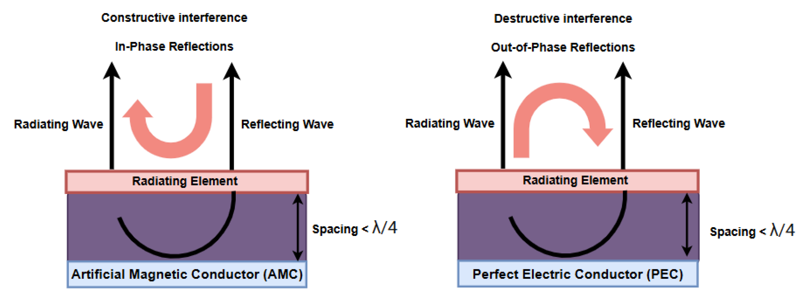
Figure 2.
AMC Unit Cell Structure Design Evolution: a) Square Patch; b) Meandered Cross; c) Final Interdigitated Comb Structure; d) Main geometrical parameters.DL1=1.06 mm; DL11=1.3 mm; DL21=0.43 mm; ML1=0.87 mm; ML2=0.87 mm; L1=5.78 mm; g1=0.30 mm.
Figure 2.
AMC Unit Cell Structure Design Evolution: a) Square Patch; b) Meandered Cross; c) Final Interdigitated Comb Structure; d) Main geometrical parameters.DL1=1.06 mm; DL11=1.3 mm; DL21=0.43 mm; ML1=0.87 mm; ML2=0.87 mm; L1=5.78 mm; g1=0.30 mm.
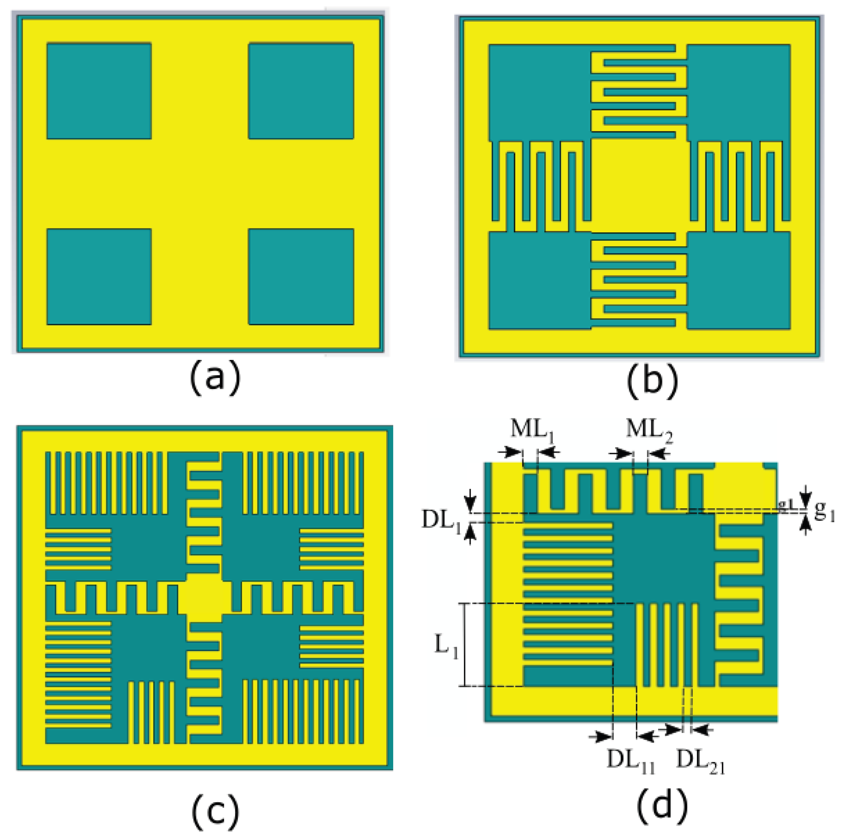
Figure 3.
Frequency response of the proposed AMC cell for the four evolution steps: (a) Reflection coefficient magnitude and (b) phase.
Figure 3.
Frequency response of the proposed AMC cell for the four evolution steps: (a) Reflection coefficient magnitude and (b) phase.
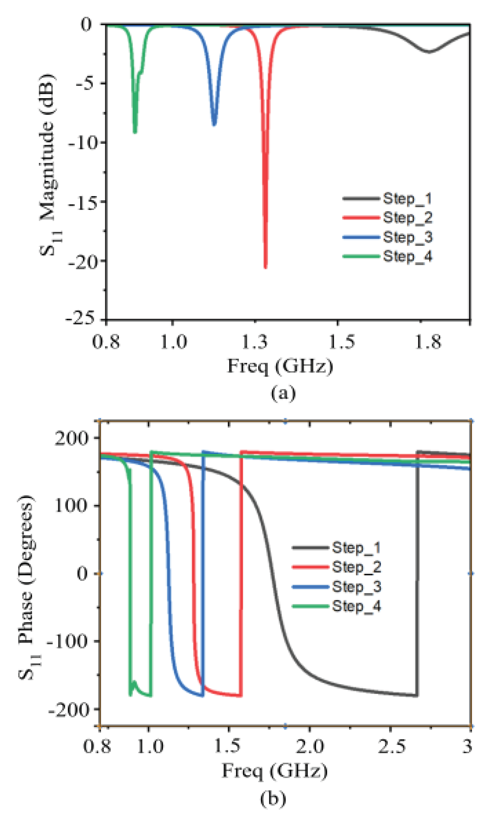
Figure 4.
Frequency response of the final optimized AMC (fourth evolution step).
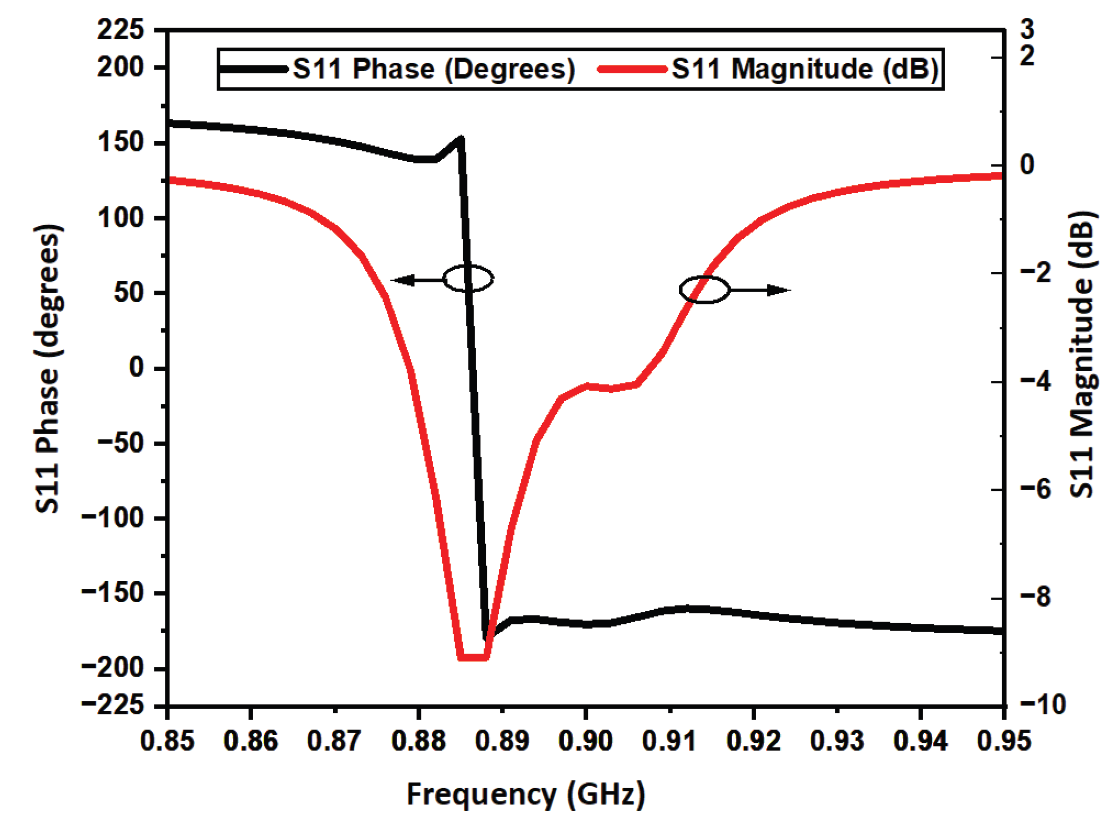
Figure 5.
Frequency response of the proposed AMC cell for different substrate thicknesses: (a) Reflection coefficient magnitude and (b) phase.
Figure 5.
Frequency response of the proposed AMC cell for different substrate thicknesses: (a) Reflection coefficient magnitude and (b) phase.
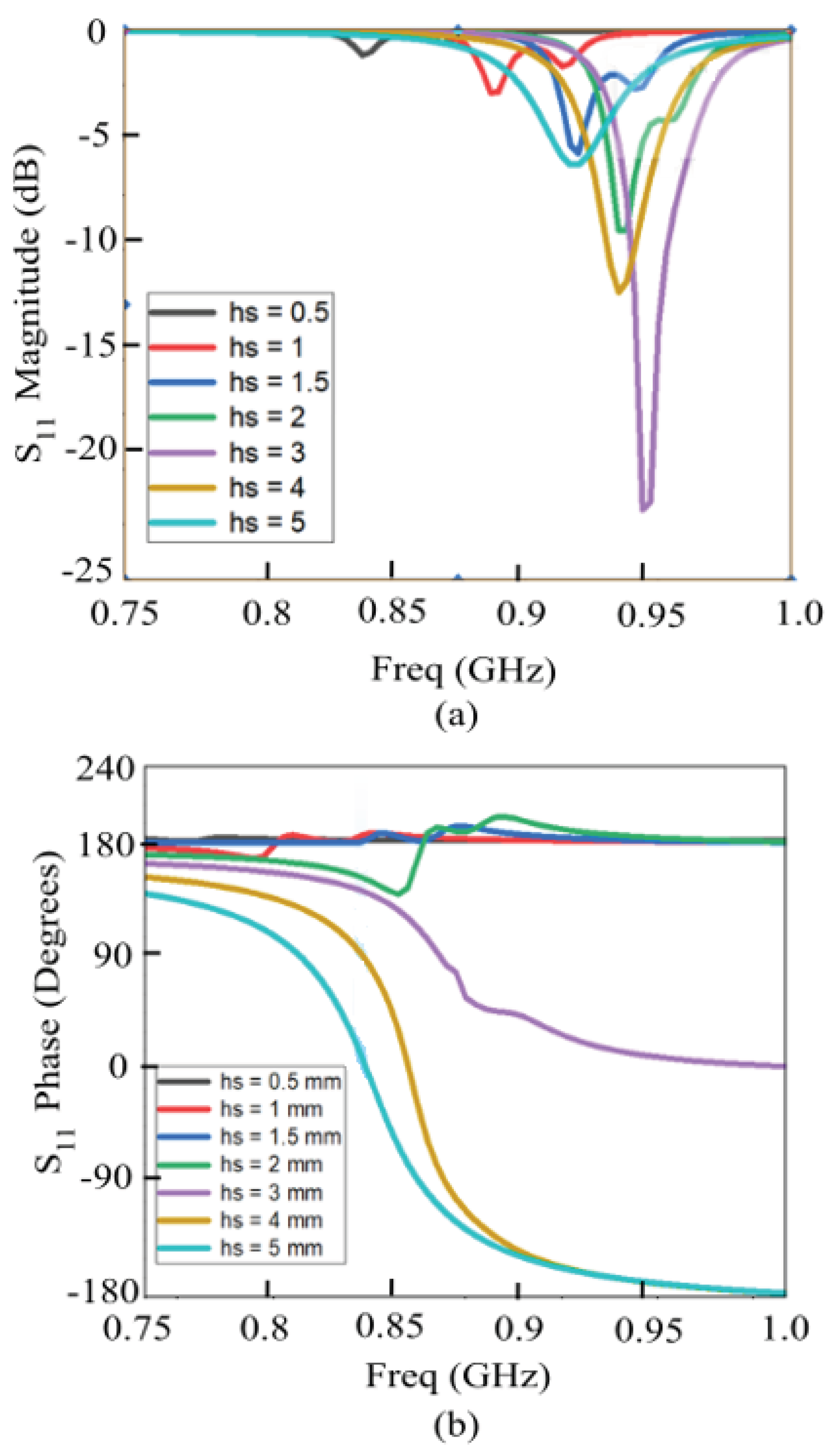
Figure 6.
Proposed multi-strip slotted RFID tag antenna Design. LTAG=59.43 mm; WTAG=17.29 mm; L=49.71 mm; W1=16.21 mm; Wa=7.56 mm; La=7.56 mm; g1=0.54 mm; g2=1.08 mm; g3=0.5 mm; g4=0.4 mm; g5=0.54 mm; g6=0.54 mm; g7=0.67 mm; L1=2.16 mm; L2=1.62 mm; Lt1=4.5 mm; Lt2=13.75 mm; Wg=3.35 mm; Wt=1.7 mm.
Figure 6.
Proposed multi-strip slotted RFID tag antenna Design. LTAG=59.43 mm; WTAG=17.29 mm; L=49.71 mm; W1=16.21 mm; Wa=7.56 mm; La=7.56 mm; g1=0.54 mm; g2=1.08 mm; g3=0.5 mm; g4=0.4 mm; g5=0.54 mm; g6=0.54 mm; g7=0.67 mm; L1=2.16 mm; L2=1.62 mm; Lt1=4.5 mm; Lt2=13.75 mm; Wg=3.35 mm; Wt=1.7 mm.
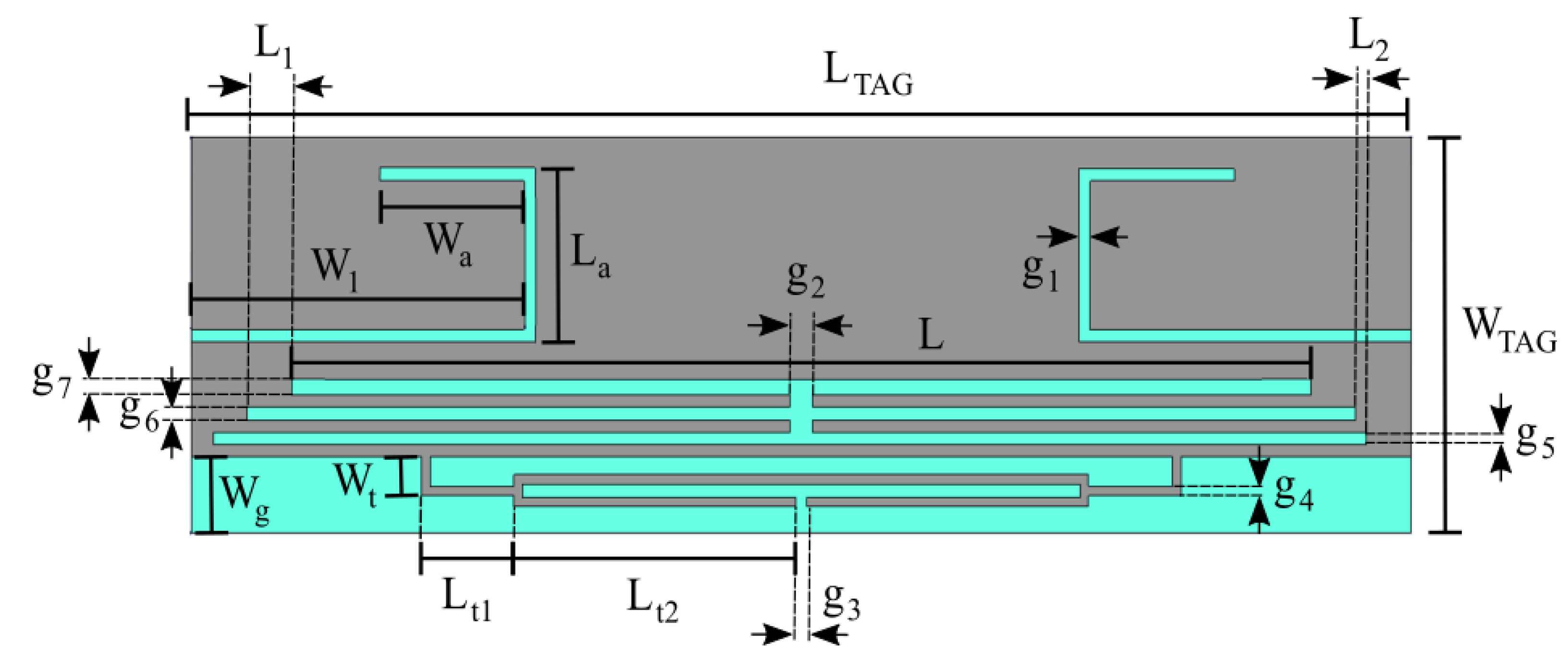
Figure 7.
Frequency response of the designed TAG. (a) Input impedance (Rin, Xin). (b) Transmission coefficient (τ).
Figure 7.
Frequency response of the designed TAG. (a) Input impedance (Rin, Xin). (b) Transmission coefficient (τ).
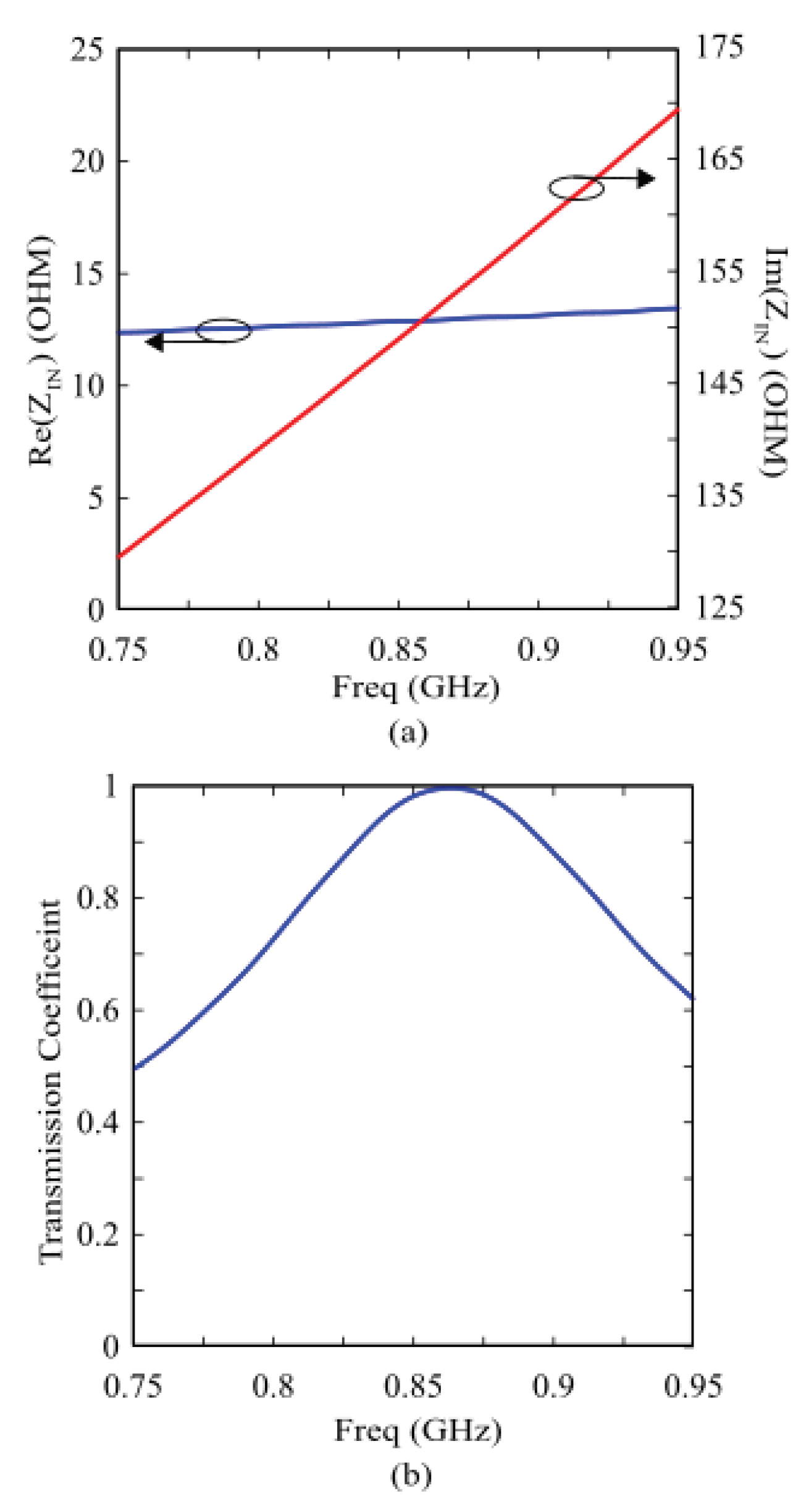
Figure 8.
Simplified multilayer human body model.
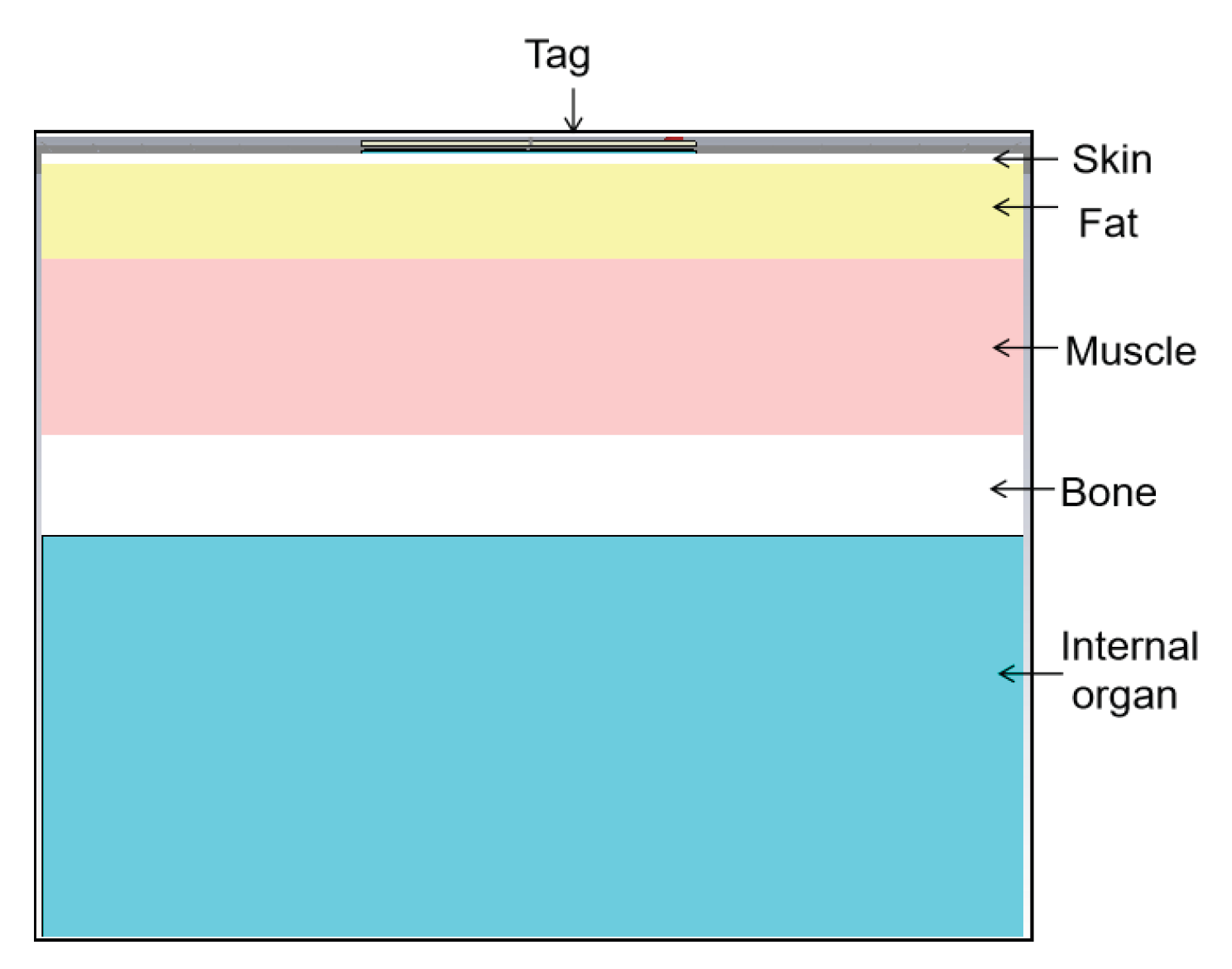
Figure 9.
Results for the designed TAG directly attached to the phantom. (a) Top view; (b) TAG Input Impedance; (c) TAG transmission coefficient; (d) TAG realized gain.
Figure 9.
Results for the designed TAG directly attached to the phantom. (a) Top view; (b) TAG Input Impedance; (c) TAG transmission coefficient; (d) TAG realized gain.
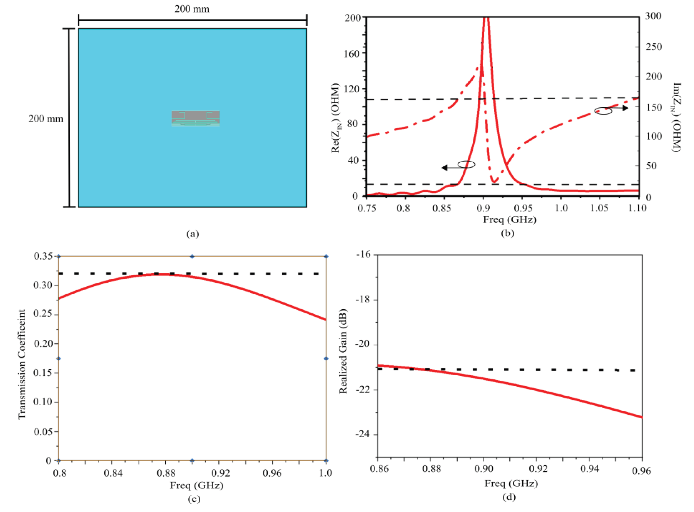
Figure 10.
Designed AMC-Backed RFID Tag Antenna.LO=64.24 mm; LV=32.12 mm; LC=31.25 mm; Gap1=0.87 mm; Gap2=0.43 mm.
Figure 10.
Designed AMC-Backed RFID Tag Antenna.LO=64.24 mm; LV=32.12 mm; LC=31.25 mm; Gap1=0.87 mm; Gap2=0.43 mm.
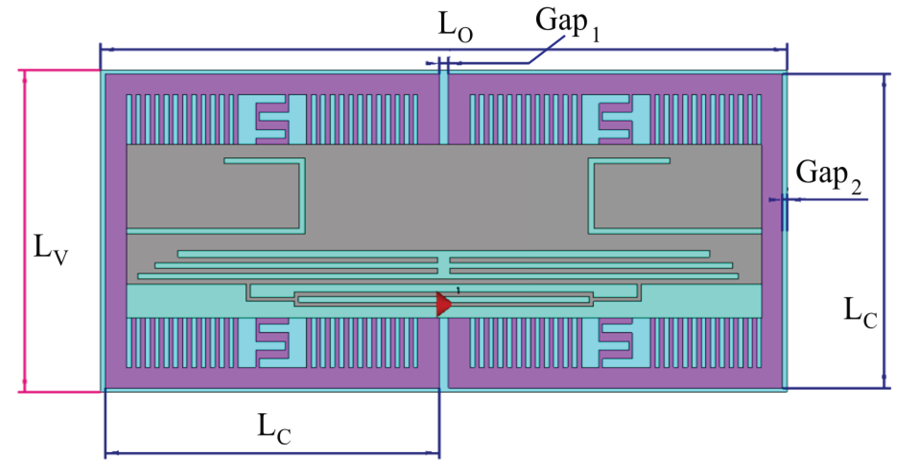
Figure 11.
Results for the designed TAG with AMC on phantom. (a) Transmission coefficient; (d) Realized gain.
Figure 11.
Results for the designed TAG with AMC on phantom. (a) Transmission coefficient; (d) Realized gain.
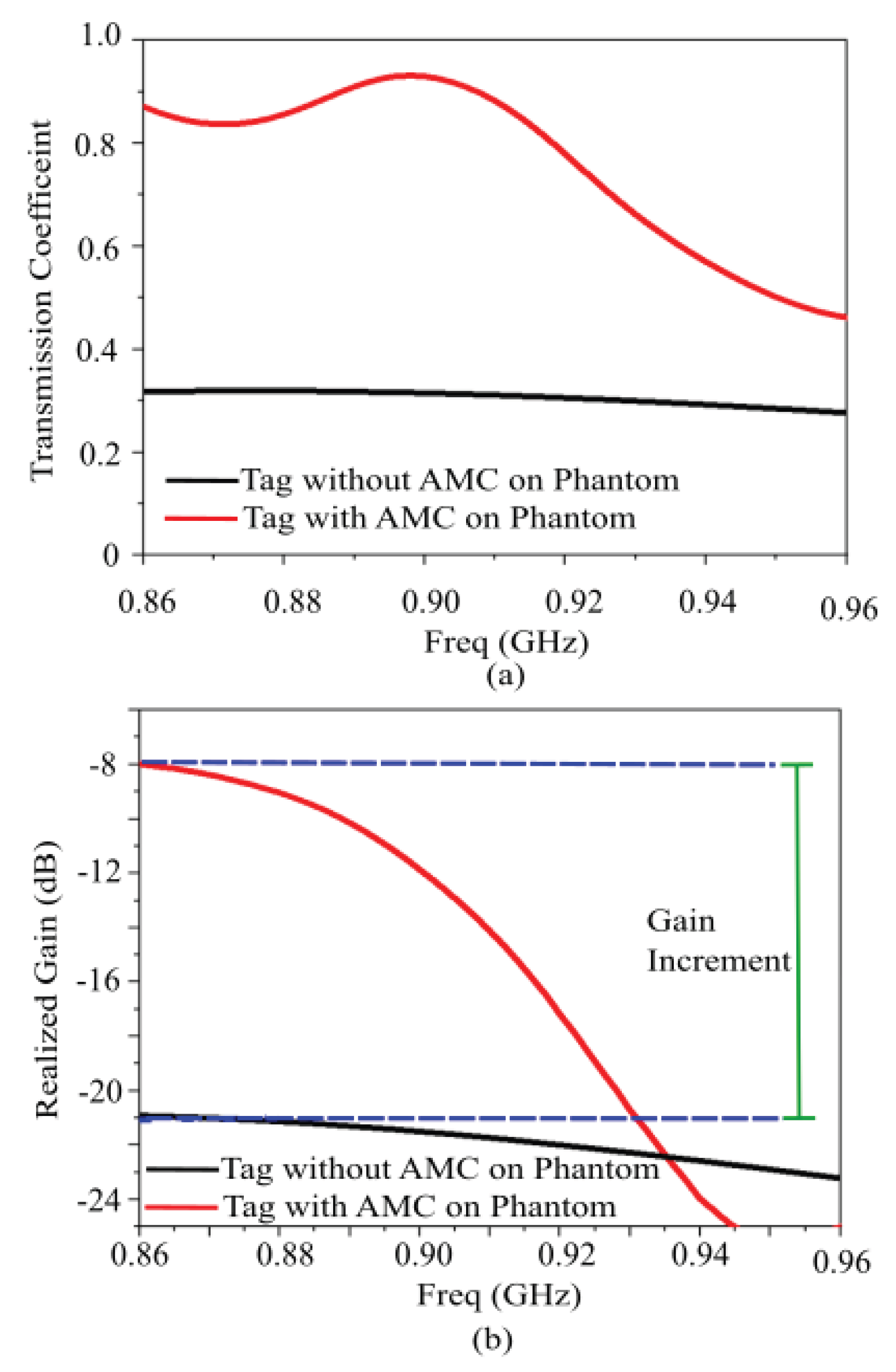
Figure 12.
Normalized far field pattern (a) when the tag is directly attached to the phantom and (b) when the tag is placed upon the tailored AMC structure. Comparison between the Far Field Patterns: (c) E-Plane; (d) H-Plane.
Figure 12.
Normalized far field pattern (a) when the tag is directly attached to the phantom and (b) when the tag is placed upon the tailored AMC structure. Comparison between the Far Field Patterns: (c) E-Plane; (d) H-Plane.
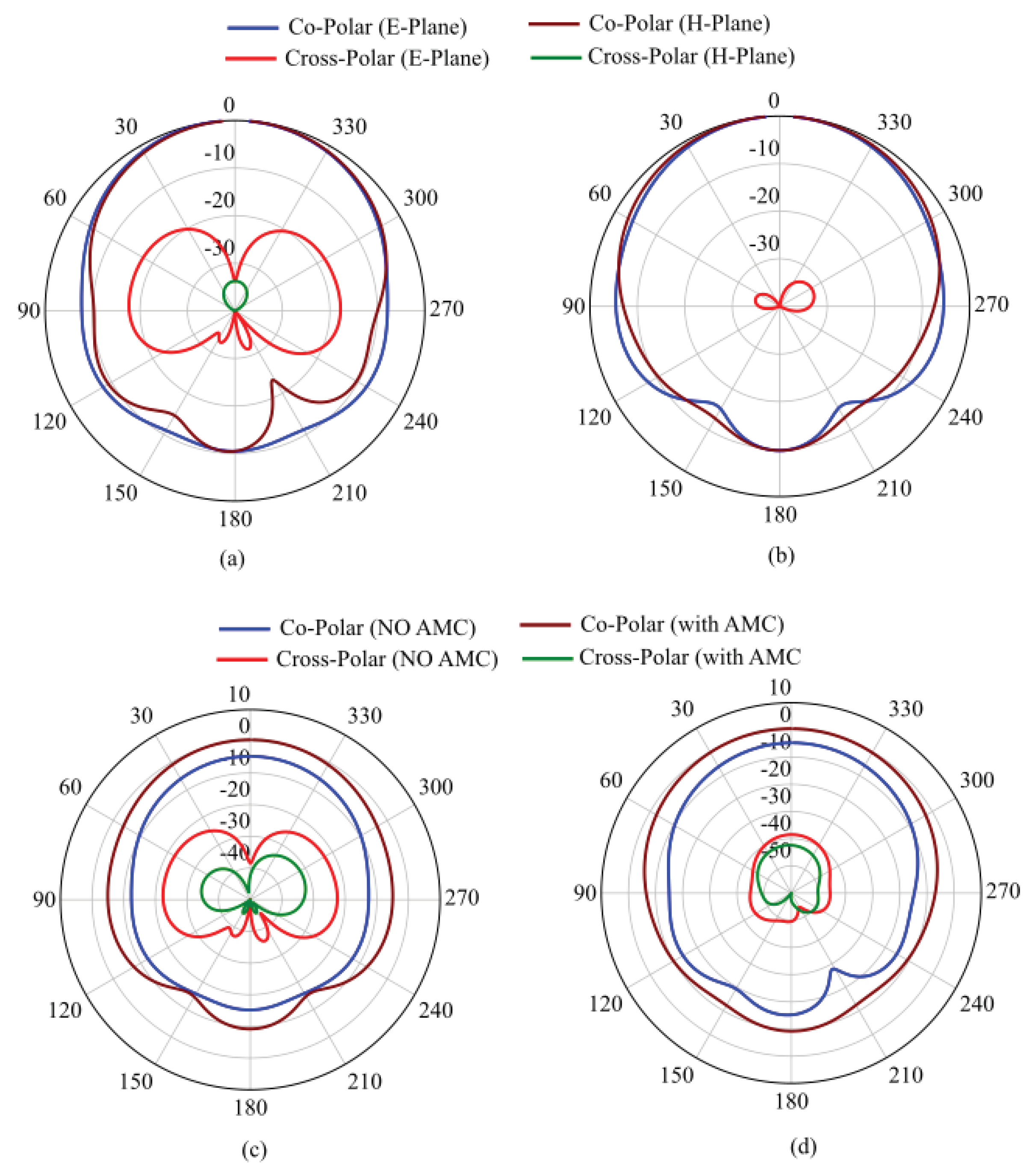
Figure 13.
SAR values when the tag is placed upon the tailored AMC structure for (a) 10g and (b) 1g tissue masses. SAR values when the tag is directly attached to the phantom for (c) 10g and (d) 1g tissue masses.
Figure 13.
SAR values when the tag is placed upon the tailored AMC structure for (a) 10g and (b) 1g tissue masses. SAR values when the tag is directly attached to the phantom for (c) 10g and (d) 1g tissue masses.
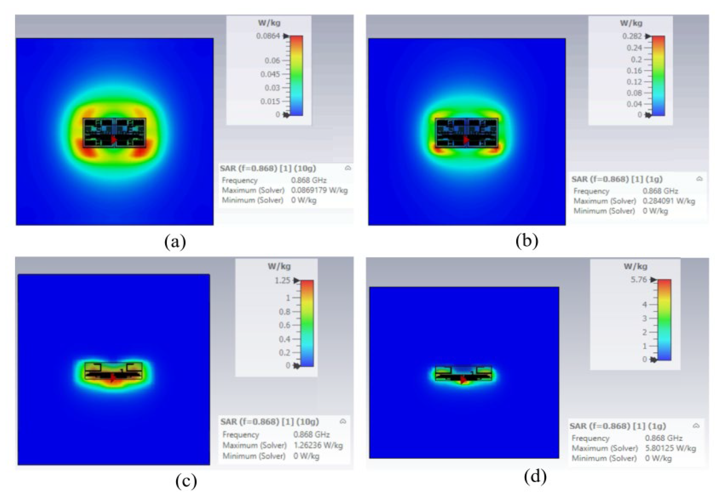
Figure 14.
a) Simulated Power Transmission Coefficient and (b) Realized Gain for the proposed AMC-Backed RFID Tag Antenna attached to the multilayer leg model for different radii Rm of muscle layer, and hence for different bending diameters.
Figure 14.
a) Simulated Power Transmission Coefficient and (b) Realized Gain for the proposed AMC-Backed RFID Tag Antenna attached to the multilayer leg model for different radii Rm of muscle layer, and hence for different bending diameters.
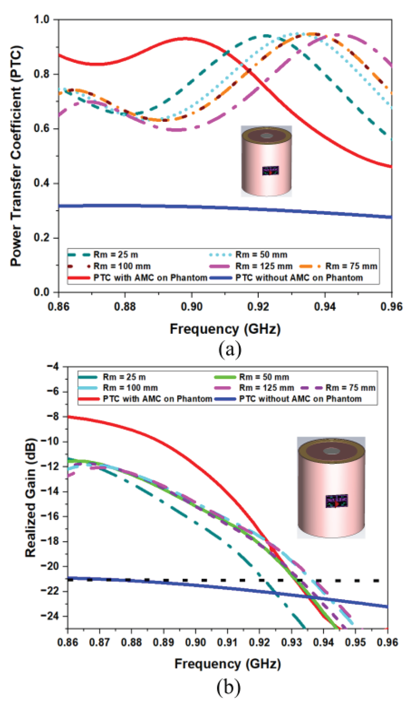

Table 1.
Comparison with the State-Of-The-Art for AMC-backed wearable antennas.
| Ref. | f0 (MHz) | Substrate (ϵr) | Height (mm) | Area (λ2) | Gain On Body (dBi) | Gain on Body with AMC (dBi) | Δ Gain (dB) | Flexible | AMC Sub. | Biocompatible | Air Gap | Platform Tolerant |
|---|---|---|---|---|---|---|---|---|---|---|---|---|
| [42] | 2450 2550 2560 |
Felt (1.3) | 2 mm + 7 mm foam | 0.0267 | 0.36 (skin) -2.94 (3-layer) -4.20 (4-layer) -3.45 (arm) |
4.13 4.05 4.21 3.15 |
(stable) 6.6 dBi |
Yes | Yes |
Yes |
7 mm |
Yes* |
| [43] | 2450 | cotton (1.6) | 3.8 | 0.1925 | 5.72 | 7.09 | 1.37 | Yes | Yes | Yes | 3 mm | Yes* |
|
[44] |
2400 | Flexible denim (1.7) | 3 | 0.2304 | -1.2 | 6.98 | 8.18 | Yes | Yes | Yes | 1 mm | Yes* |
| [45] | 865 3450 4100 |
FR4 (4.2) | 6.52+1.52 | 0.0362 | 4.55 5.03 5.6 / 3.15 |
4.61 6.24 3.26 |
1.21 | No |
No |
No | No |
No |
| [46] | 5800 | Jeans (2) | 3.2 | 2.014 | 0.99 | 4.88 | 5.3 | Yes | Yes | Yes | No | Yes |
| [49] | 868 | 6.24 | 2.8 | 0.0283 | -15.3 | - | - | No | No | Yes | No | No |
| [50] | 915 | 4.4 | 6.4 | 0.422 | -2.44 | 5.01 | 7.45 | No | Yes | No | ||
| [51] | 868 | 2.8 | 4.18 | 8.8/103 | -18.1 | - | - | No | No | Yes | No | No |
| This Work | 868 | doped Silicon (6.24) | 2.23 | 0.0246 | -21 dB | -8 dB | 13 dB | Yes | Yes | Yes | No | Yes |
*Claims tolerance but requires specific spacing or air gaps to maintain resonance.
Table 2.
Electromagnetic parameters and thickness of the multi-layer human body model (at 866 MHz).
| Material (Bio-Tissue) |
Thickness (mm) |
Permittivity ϵr | Conductivityσ ([S/m]) | Density ρ ([kg/m³]) |
|---|---|---|---|---|
| Skin | 2 | 41.3 | 0.89 | 1100 |
| Fat | 20 | 5.46 | 0.05 | 910 |
| Muscle | 37 | 55.0 | 0.94 | 1041 |
| Bone | 21 | 20.8 | 0.34 | 1850 |
| Internal Organs | 84 | 52.1 | 0.91 | 1000 |
Table 3.
SAR Values on Human Model.
| Tissue weight | 1 g | 10 g |
| Tag placed on tailored AMC | 5.76 | 1.25 |
| Tag Placed directly | 0.282 | 0.0864 |
Disclaimer/Publisher’s Note: The statements, opinions and data contained in all publications are solely those of the individual author(s) and contributor(s) and not of MDPI and/or the editor(s). MDPI and/or the editor(s) disclaim responsibility for any injury to people or property resulting from any ideas, methods, instructions or products referred to in the content. |
© 2026 by the authors. Licensee MDPI, Basel, Switzerland. This article is an open access article distributed under the terms and conditions of the Creative Commons Attribution (CC BY) license (http://creativecommons.org/licenses/by/4.0/).
Copyright: This open access article is published under a Creative Commons CC BY 4.0 license, which permit the free download, distribution, and reuse, provided that the author and preprint are cited in any reuse.


