
Submitted:
26 April 2025
Posted:
28 April 2025
You are already at the latest version
Abstract
This paper presents the effects of effective dielectric properties of human torso on carrier-link-margin (CLM) and data-link-margin (DLM) of an experimentally validated miniaturized corner-chamfered meander-line implantable antenna placed within an implantable system prototype consisting of battery, PCB, camera and sensor encapsulated by biocompatible gelatin at 2.5 GHz. Specific Absorption Rate (SAR) and link margin performances of the implanted antenna are analyzed for 2500 scenarios (±20% variations in reference to the mean values of the effective relative permittivity, ɛeff, and conductivity, σeff, of the human body). For accurate dependence analyses, an artificial neural network (ANN) with two input variables (ɛeff, σeff) and five output variables (SAR_1g, SAR_10g, fractional bandwidth, CLM and DLM) is trained by 80% and tested by 20% of the total scenarios. Compared with the reference effective electrical properties of the homogeneous human body model, respective maximum variations of 63%, 41.6%, 17.97%, 26.79%, and 5.89% are observed in 1 g SAR value, 10 g SAR value, fractional bandwidth, CLM and DLM at 4 m distance for 100 Kbps. This work pioneers accurate dependences of link margins of body-implantable antenna system on effective relative permittivity and conductivity analyses.
Keywords:
Biotelemetry
; Carrier Link Margin
; Data Link Margin
; Implantable Antenna
; Meander-line
; Specific Absorption Rate
1. Introduction
In the last two decades, the popularity of medical bio-telemetry devices has escalated interest in therapeutic and diagnostic functions for continuous patient monitoring in applications like temperature, heartbeat, glucose level detection, heart rate regulation, drug delivery and pain control [1,2,3]. Implantable antennas embedded in these medical devices can transfer the patients’ health-related sensed data to the doctor’s end wirelessly to save them from a sudden death or a critical condition with the help of the emerging Internet of Medical Things (IoMT) technology [4]. Erroneous communication link characterization may cause data loss, which leads to the misinterpretation of the patient’s health condition and wrong diagnosis. The quality of communication (or link margin), includes the gains of the implantable antenna and the external monitoring device’s antenna, operating frequency, transmitted power, path loss, polarization of the antennas, data rate, and signal-to-noise ratio (SNR) [5]. Figure 1 shows a schematic of wireless telemedical communication between an implantable antenna and an external monitoring device. Previously, inductive coupling was utilized for an implant communication. However, this communication technique has some limitations, viz: low data rates (1-30 kbps), low communication range (less than 10 cm) and low sensitivity of the coils [6,7]. To overcome these restrictions, medical implant communications are performed at different frequencies, such as Medical Implant Communication Service (MICS) (402 – 405 MHz); Wireless Medical Telemetry Service (WMTS) (608 – 614, 1395 – 1400 and 1427 – 1432 MHz), and Industrial, Scientific and Medical (ISM) bands (such as 2.4-2.5 GHz, 5.73-5.88 GHz etc.) [8,9].
Implantable antennas have significant challenges, including developing miniaturized prototypes, achieving an agreement with safety guidelines regarding Specific Absorption Rate (SAR) and measuring the dielectric properties of tissues [10,11,12]. According to electromagnetic regulatory guidelines [13,14,15,16,17], SAR averaged over 1 g and 10 g of contiguous cubical tissue should be less than 1.6 W/Kg and 2 W/Kg respectively at 2.5 GHz. As the wireless communication link of the implantable antenna with the monitoring device is established through the human tissue, this communication performance depends on the bioelectric properties of tissue, viz: relative permittivity and conductivity. Relative permittivity of human tissues is dependent on factors like age, gender of patients, location of implant, thickness of skin and fat layers and hormonal variations in patients’ bodies. [18,19,20,21,22,23]. It is also dependent on the water and oil content, the structure of fibers, etc. 0.4 – 0.6 mm thick stratum corneum (a part of the epidermis of the skin layer) contains comparatively lower water content (around 10%) [24]. Hwang et al. [25] and Boric-Lubecke et al. [26] showed that the effective complex permittivity of different body parts is not the same. The generation of tumors in any layer may increase effective complex permittivity by about 20%. The effective dielectric properties can also change due to pathological changes in the liver due to cirrhosis, steatosis and, hepatocellular carcinoma. [27]. Therefore, it is enough to study the possible variation in link performance by considering ±20% variations in mean bioelectric properties of the overall human body.
Effective loss in channels can change due to variations in the electrical properties of the biological environment of the implanted antenna, which may lead to varying communication link performance metrics. For small size and low mass anatomical models, the realized gain and the radiated power of the implanted antenna are low. The impact of anatomical variations in the relative permittivity and conductivity of the human body model due to skin and fat thickness variations on reflection coefficient (S11) and fractional bandwidth of an implantable antenna at MICS (402-405 GHz) was assessed in [28]. Authors in [29] studied the dependence of S11 and bandwidth of an implantable rectangular patch antenna on the relative and conductivity of different tissues such as fat, kidney, liver, muscle, gray matter, white matter, different ages, gender, height and mass of the patients. In the literature survey, the dielectric parameters of human tissue also influence the performance of implantable antenna. The detuning of an implantable antenna in terms of reflection coefficient due to relative permittivity and conductivity of the human body was studied in [30]. In [3], the authors investigated the dependence of S11, resonant frequency, gain and SAR of the implantable antenna on the variations of the dielectric constant of the human head and body model. They performed their investigations by taking a very small number of samples, which were not sufficient to analyze their dependencies. The communication link is also dependent on the variation of the data rate, the uncertainties of channel properties etc.
In this article, a corner-chamfered meander-line implantable antenna was designed within an equivalent homogeneous human body model (mean tissue permittivity = 52.7 and mean conductivity = 1.95 S/m) and exhibited communication performance was studied at 2.45 GHz ISM band (dedicated for medical investigations by FCC). A frequency shift of 25 MHz from reference frequency was observed for ±20% variation in mean relative permittivity and conductivity values of the human body. Due to this possible variation of the bioelectrical properties, peak SAR and its distribution due to the placement of implantable antenna are changed, which has been studied here. To limit the SAR value as per safety guidelines, input power should be controlled properly, and the input power is one of the main parameters for the link margin to characterize the communication quality. The bandwidth of an implantable antenna is another important parameter for communication because it can characterize the channel capacity of wireless communication based on Shannon’s channel capacity theorem. Link margin includes a gain of the implanted antenna, the distance between the implanted antenna and monitoring device, a gain of the antenna of the monitoring antenna, different communication characteristics in terms of signal-to-noise ratio, type of modulation and data rate. There are two parts of Communication link margin – (a) carrier-link-margin (CLM) related to carrier signal-to-noise ratio and (b) data-link-margin (DLM) related to data signal-to-noise ratio [30],[31]. There is no reported work related to the dependences of the CLM and DLM along with SAR profile to ensure a reliable and safe wireless patient monitoring on the effective body electrical properties. This paper closes the research gap by developing an artificial neural network (ANN) to train and validate the effective properties with respect to the CLM and DLM. The ANN was trained by 80% of 2500 scenarios (±20% variations in the referenced mean relative permittivity, ɛeff, and conductivity, σeff, of the human body) and validated by 20% of them. The ANN predicted with 99.24% average accuracy with respect to the simulated and the measured responses. Compared with the referenced effective electrical properties of the homogeneous human body model, respective maximum variations of 63%, 41.6%, 17.97%, 26.79% and 5.89% are observed in 1 g and 10 g SAR value, fractional bandwidth, CLM and DLM at 4 m distance for 100 Kbps.
The novelty of this work compared with previous works reported in [32,33,34,35,36,37,38,39] is highlighted in Table 1. The significance and timeliness of this work are summarized below.
(i) Table 1 concludes that this is the first work where the carrier link margin and the data link margin of a muscle-implanted antenna with an external monitoring device were performed.
(ii) The SAR value (220.26 W/kg) for a 1-g tissue at 1W input power ensures the patient’s safety after implantation compared with the existing work.
(iii) The performance matrices [including signal radiation (gain) and reflection (S11)] within the body model are comparable with the leading implantable antennas.
(iv) The authors in [36] designed an implantable antenna which could communicate up to 13 m variation. In [38], the effect of phantom size on the gain and the efficiency of the spiral-implanted antenna were discussed. The possibility of variations in S11 and frequency of an implanted antenna due to variation in relative permittivity of the body was observed in [39] based on only 6 samples of permittivity values. Our work takes a comprehensive approach to investigate and validate the impact of both human body electrical parameters (including effective relative permittivity and conductivity) on the link margins (CLM, DLM). The prevailing performance matrices for potential IoMTs applications include operating frequency, realized gain, data rate, channel loss, range of communication, bandwidth, and SAR signature of the implanted antenna.
(v) 2500 samples of effective body models were considered, and ANN modelling was performed to analyze the accuracy of the dependence. The innovative use of ANN in this field further underlines the pioneering nature of this research.
(vi) This work presents the first extensive human body electrical properties dependence analysis of the SAR profile and communication link performance of implantable antennas.
(vii) The reported research findings will aid the innovative development of 5G/6G IoMTs devices for existing and/or emerging wearable technology use cases and/or applications.
Figure 2.
Geometry of the corner-chamfered implantable antenna: (a) Top view and (b) Bottom view.
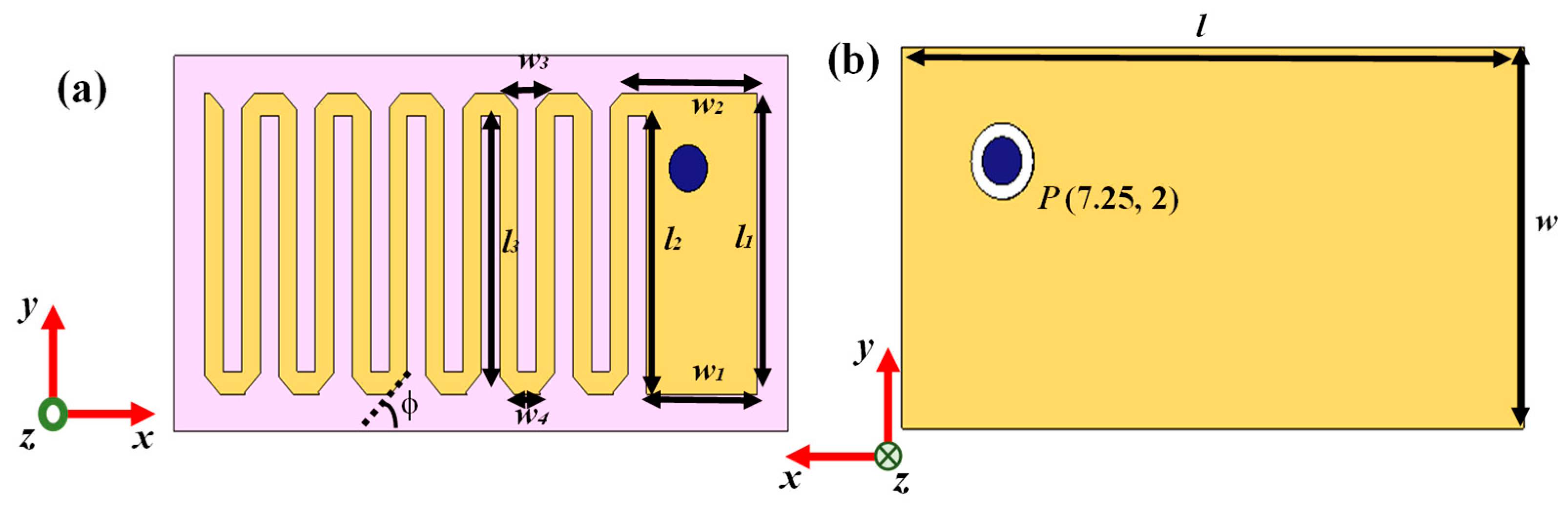

Table 2.
Parameters of Implantable Antenna.
| Parameters | Values | Parameters | Values |
|---|---|---|---|
| l | 20 mm | w2 | 4.397 mm |
| w | 10 mm | w3 | 1.46 mm |
| l1 | 8 mm | w4 | 0.86 mm |
| w1 | 3.6 mm | φ | 45o |
| l2 | 7.4 mm | P | (7.25 mm, 2 mm) |
2. Models and Methods
2.1. Implantable Transmitting Antenna System Design
2.1.1. Design Procedure
The geometry of designed 152.4 mm3 antenna within implantable medical device is illustrated in Figure 2 and the parameters of the antenna are listed in Table 2. The radiator part of this antenna was printed on Arlon AD 430 dielectric substrates with a thickness of 0.762 mm. Meandering was performed here to lengthen the effective current path, which led to an increase in the effective wavelength with miniaturized structure. Corner-chamfering was performed to reduce the stray radiated emission to minimize losses and unwanted reactance [40]. For proper analysis of the communication and SAR performance, a prototype of implantable medical device (shown in Figure 3) containing the corner-chamfered antenna, camera, PCB and sensor encapsulated by 0.5 mm thick biocompatible coating made of 10 g gelatin and 15 g deionized (DI) water which has relative permittivity of 41.57 and loss tangent of 0.39 at 2.45 GHz, was taken. A coaxial probe with 0.63 mm probe radius providing input impedance of 50 Ω was used for exciting the antenna system.
2.1.2. Simulation Setup
The corner-chamfered antenna was implanted within a 100 mm X 100 mm X 100 mm cubical mean Homogeneous Human Body Model (HHBM) at the center as shown in Figure 4. The HHBM has a relative permittivity of 52.7 and conductivity of 1.95 S/m based on FCC guideline [41]. HHBM was enclosed by an airbox which is considered as radiation boundary of the implanted system. Numerical simulations were performed using Finite Element Method (FEM) method using CST MWS 2019 commercial software. Here, a Gaussian source was fed to the implanted antenna and frequency response was measured at 2.5 GHz.
2.1.3. Design Evolution
The design steps of the implantable antenna are shown in Figure 5. An initial patch with size of 18 mm X 8 mm was designed on substrate, resulting in poor S11 response at operating frequency of 3.18 GHz. In Step 2, a meander-line was created at the opposite edge of excited part by etching two 0.6 mm slots as shown in Figure 5. The operating frequency was shifted to 2.82 GHz and S11 was improved to -18.05 dB. The incorporation of slots increased effective guided wavelength by increasing equivalent capacitance. To tune the operating frequency within 2.45 GHz ISM band (2.4-2.5 GHz), more symmetrical slots were etched to increase meander-line numbers. After creating six meander-line slots as shown in Figure 5, the operating frequency was tuned at the desired band. The reflection coefficient (S11) of this antenna architecture was observed as -15.59 dB. The realized gain of this antenna was -47.28 dBi. To improve the antenna responses in terms of S11 and gain, the chamfering of the corners were performed. Operating frequency was not varied due to chamfer; however, reflection coefficient was improved to -45.87 dB and realized gain was increased to -38.42 dBi. The simulated antenna possessed a fractional bandwidth of 5.67%.
Figure 5.
Design Evolution steps of implantable antenna within human body model and their reflection coefficients (dB).
Figure 5.
Design Evolution steps of implantable antenna within human body model and their reflection coefficients (dB).
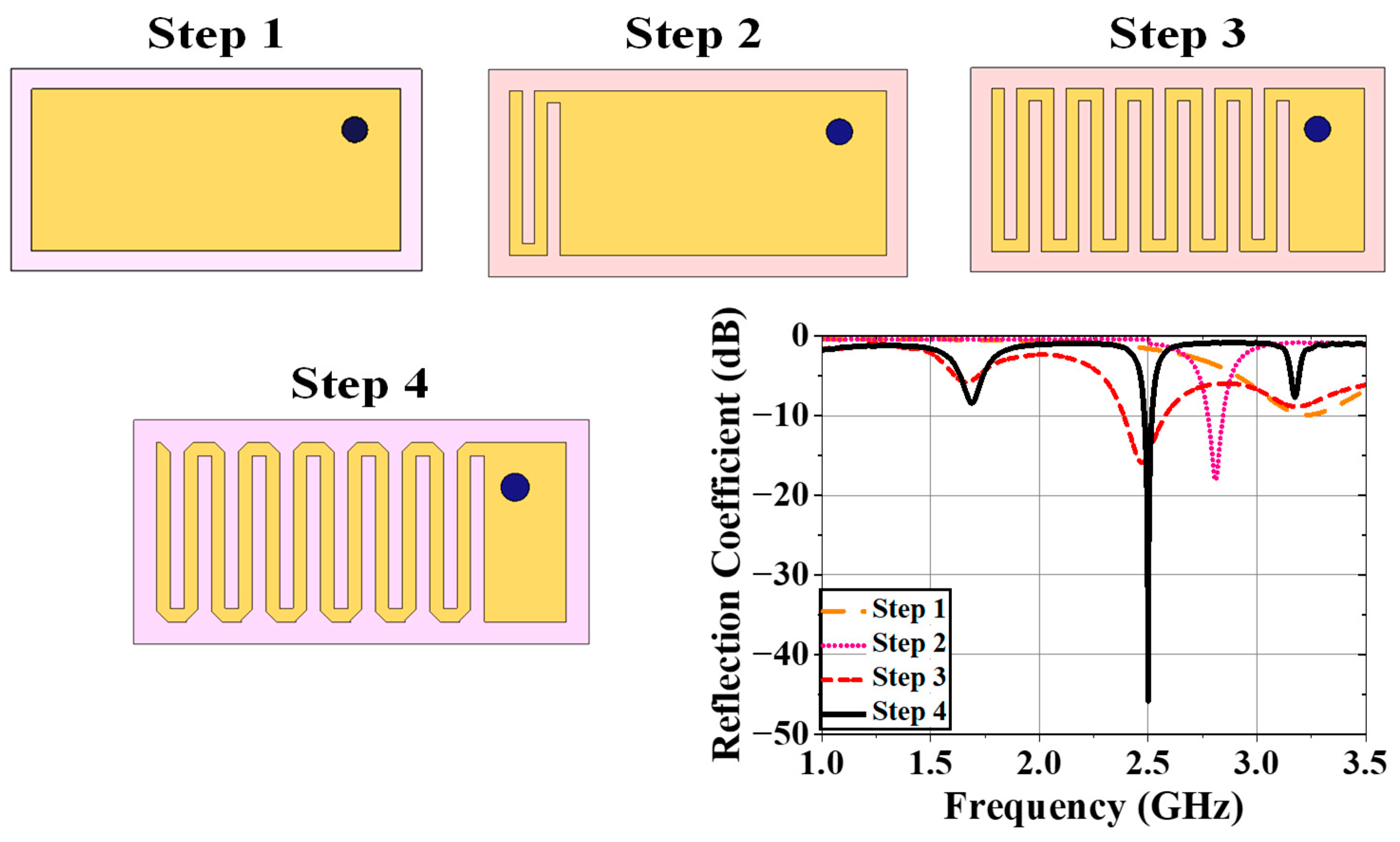
Figure 6.
(a) Surface current distribution on patch of antenna at 2.5 GHz; 3D 1W SAR plots (Y=0 calibration) for (b) 1g and (c) 10g tissue.
Figure 6.
(a) Surface current distribution on patch of antenna at 2.5 GHz; 3D 1W SAR plots (Y=0 calibration) for (b) 1g and (c) 10g tissue.
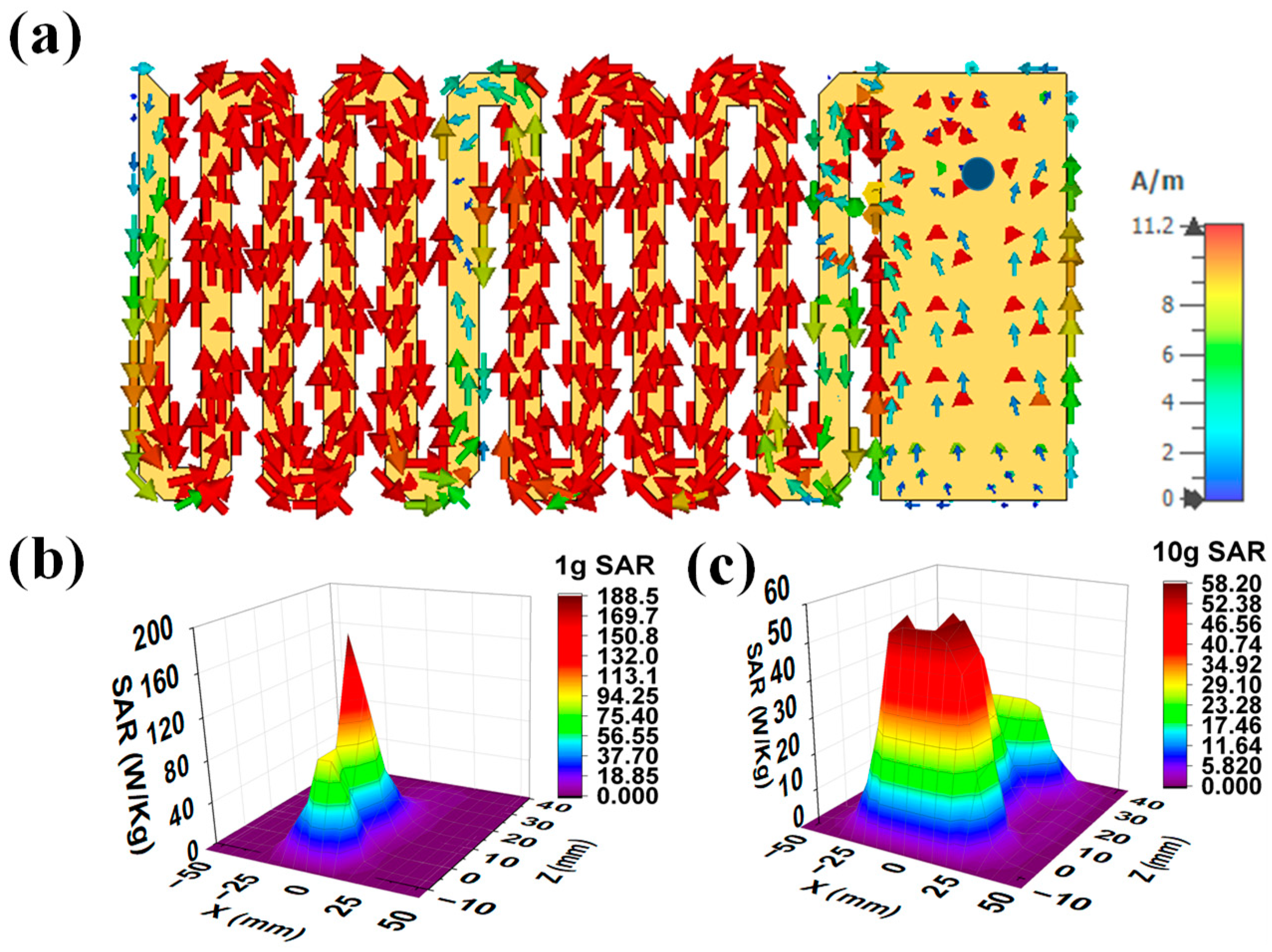
2.1.4. Current Distribution and SAR profile
Figure 6 (a) shows the surface current distribution of the final antenna radiator at 2.5 GHz. This current was injected through 50Ω coaxial probe from RF source. From this figure, the current was distributed from connector to the patch surface. The currents were highly dense at the edges of meander-lines. The safety performance of the implanted antenna was evaluated in terms of compliance with international safety guidelines, the IEEE Std. C95.1-2019 [41] guideline. Initially, 1 W average input power was applied to the implanted antenna to observe the SAR distributions for 1 g and 10 g contiguous models. The maximum SAR for the 1 g and the 10 g should be less than 1.6 W/kg and 2 W/kg, respectively, as per the standard guidelines [41]. The peak SAR values for the 1 g and 10 g cubical tissues were obtained as 220.26 W/kg and 59.73 W/kg respectively. The maximum input powers for 1 g and 10 g of body tissues were 7 mW and 24 mW respectively, for maintaining the SAR values within the standard SAR limits. Figure 6 (b) and (c) present simulated 3D 1 g and the 10 g SAR distribution for the implanted antenna respectively for a 1 W input power.
Figure 7.
(a) General block diagram of wireless patient monitoring (b) top view of receiving antenna present in external monitoring device where ltx = 90 mm, wtx = 80mm, lx1 = 38 mm, wx1 = 29 mm and lx2 = 7.5 mm (c) reflection coefficient plot of Rx antenna.
Figure 7.
(a) General block diagram of wireless patient monitoring (b) top view of receiving antenna present in external monitoring device where ltx = 90 mm, wtx = 80mm, lx1 = 38 mm, wx1 = 29 mm and lx2 = 7.5 mm (c) reflection coefficient plot of Rx antenna.
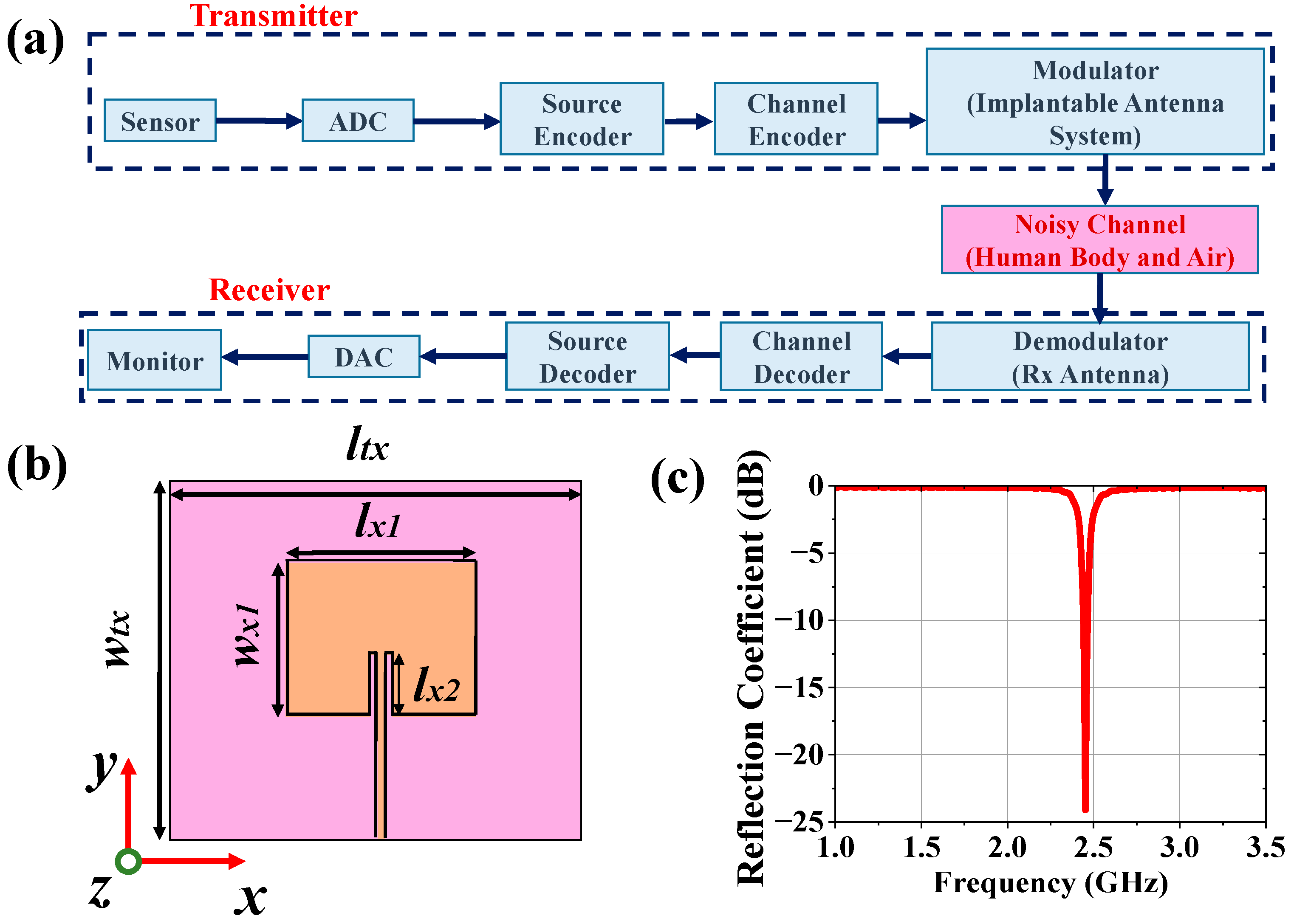
2.2. Antenna Design for Monitoring Device
The external monitoring device can wirelessly monitor the patient’s health condition by collecting sensed data from implantable antenna system tuned to the antenna of the external receiving device as illustrated in Figure 7 (a). Therefore, the receiving antenna of the external monitoring device should be tuned at 2.5 GHz. A patch antenna was designed and placed at 50 mm distance from the top surface of the phantom (refer to Figure 8 (a)). The top view of receiving patch antenna is shown in Figure 7 (b). The antenna has return loss of 24.09 dB at operating frequency 2.49 GHz with realized gain 4.95 dBi.
2.3. Communication Performance Characterization
For proper establishment of medical communication with external monitoring devices to conduct continuous patient monitoring, the link margin (L) should be calculated using (1). Based on the SAR profile, the input power of the implantable antenna will be PTX = 7mW = 8.45dBm.
L = RLink (dB) – Rreq. (dB)
RLink = PTX + GTX + GRX – 20*log(4πd/λ)
RReq. = (Eb/No) + 10*log(Dr) – GC +GD
In (2), the expression RLink represents the ratio of the Rx power the patch antenna receives at any distance (d) to the noise power density of the implanted chamfered meander lined antenna. RReq, in (3), denotes the ratio of required carrier power to noise power at the Rx end. Binary Phase Shift Keying (BPSK) modulation with normalized signal-to-noise ratio (Eb/No) of 9.6 dB was considered here, and L was calculated using the link budget parameters mentioned in Table 3 for bit rates of 7 kbps, 100 kbps and 1 Mbps. From Figure 8 (b), it was observed that the implantable antenna is able to communicate with the Rx antenna at a distance of more than 700 m for a bit rate of 7 kbps. If the value of Dr is increased to 100 kbps, the transfer range (where L (dB) = 0) is reduced to 200 m. For a further increment of data rate at 1 Mbps, implantable antenna communicates efficiently within 60 m.
2.4. Carrier-Link-Margin and Data-Link-Margin Calculation
Noise temperature is one of the important parameters of any system. Noise temperature is the measurement of equivalent level of available noise power introduced by a component or source. Let us consider the effective noise temperature of the system, which is Tsys. Therefore, the modified expression of the generalized link margin is given in (4).
L = PTX + GTX + GRX-20*log(4πd/λ)-(Eb/No) -10*log(Dr)+GC- GD- 10*log (Tsys)
Table 3.
Parameters for Link Budget Analysis.
| Parameters | Variable | Values | |
|---|---|---|---|
| Transmitter | Frequency | fr | 2.47 GHz |
| Transmitted Power | PTX | 8.45 dBm | |
| Tx Antenna gain | GTX | -38.42 dBi | |
| Receiver | Receiving Antenna gain | GRX | 4.95 dBi |
| Polarization | P | LP | |
| Temperature | To | 293 K | |
| Boltzmann Constant | K | 1.38Χ10-23 | |
| Noise Power Density | No | 199.95 dB/Hz | |
| Signal Quality | Distance | d | 1-15m |
| Ideal-BPSK | Eb/No | 9.6 dB | |
| Coding gain | GC | 0 | |
| Fixing deterioration | GD | 2.5 dB |
To characterize the wireless communication link between the implantable antenna and an external device, carrier link margin (CLM) and data link margin (DLM) were required to learn. CLM is the difference between the achieved carrier-to-noise power and the required carrier-to-noise power in human body communication, and DLM is the difference between the data signal-to-noise power achieved and the data signal-to-noise power required. The CLM and DLM are calculated using (4) for 14 K noise temperature and 100 Kbps data rate and plotted in Figure 8 (c) for variable distance (d) between the receiver and transmitting implanted antenna.
3. Dependence Analysis and Discussion
The human body model's respective mean relative permittivity (ɛeff) and conductivity (σeff) are 52.7 and 1.95 S/m as per FCC guidelines at 2.5 GHz. The electrical properties can be varied by around ±20% with respect to reference ɛeff and σeff. Therefore, two Gaussian pulses (Nɛ and Nσ) for ɛeff and σeff were taken as mentioned in equations (5-6) and sampled into 50 points. Therefore, 2500 scenarios with different combinations of ɛeff and σeff were obtained to record the implanted antenna's communication performance and SAR profile. The possible variations in medical communication performance and SAR profile due to both body-electrical properties variations were studied here.
Nɛ = {1/√(2π(Ψɛ)2}*exp[(-1/2){(ɛeff-52.7)2 / (Ψɛ)2}]
Nσ = {1/√(2π(Ψσ)2}* exp[(-1/2){( σeff- 52.7)2 / (Ψσ)2}]
Figure 9.
Effect of ±20% variation in effective relative permittivity on (a) S11, (b) realized gain, (c) fractional bandwidth, (d) 1g SAR (1watt input power) (e) 10g SAR (1 watt input power), (f) CLM (100 kbps data rate at d = 4 m) and (g) DLM (100 kbps data rate at d = 4 m) of implanted antenna system.
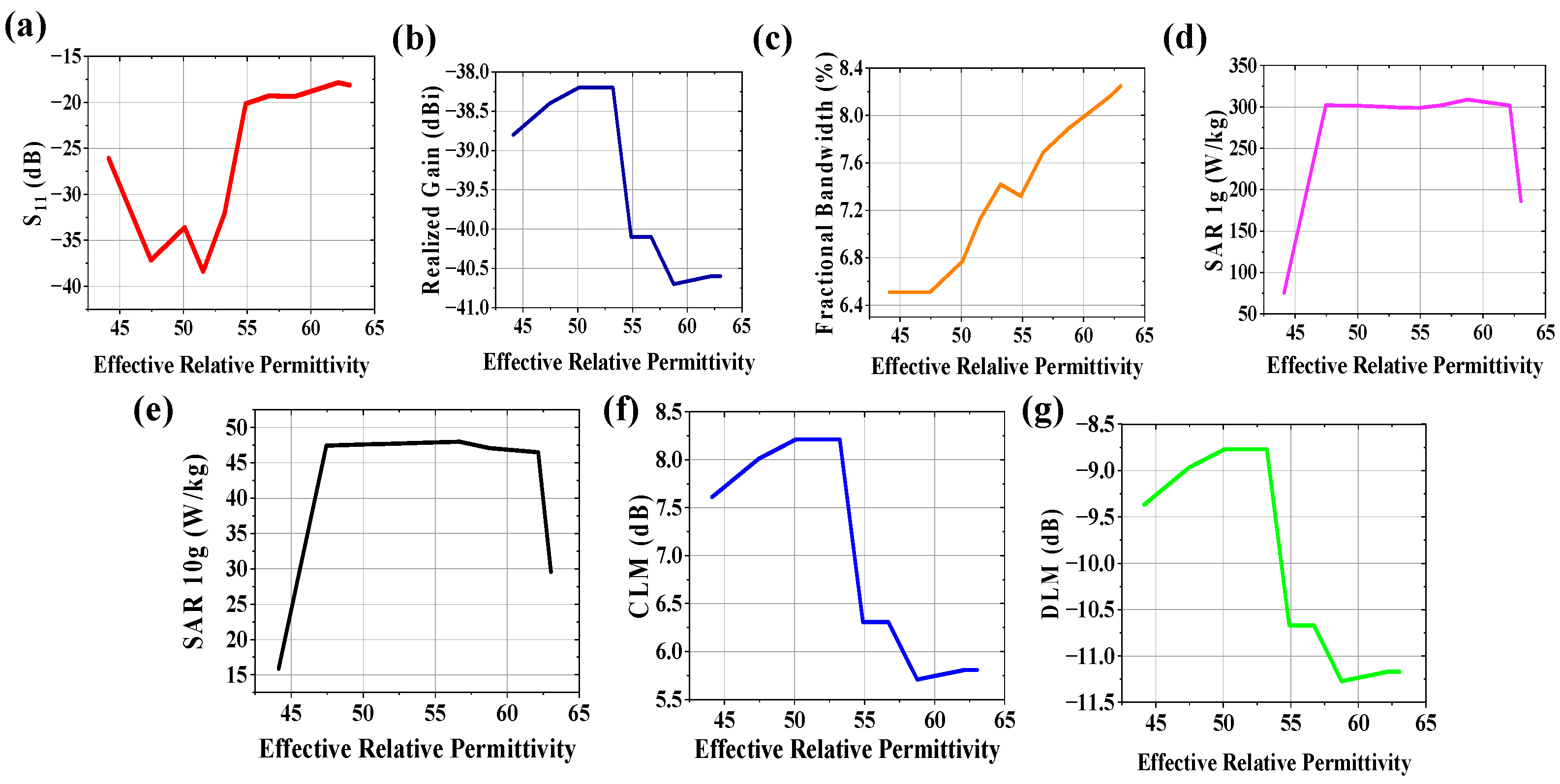
Figure 10.
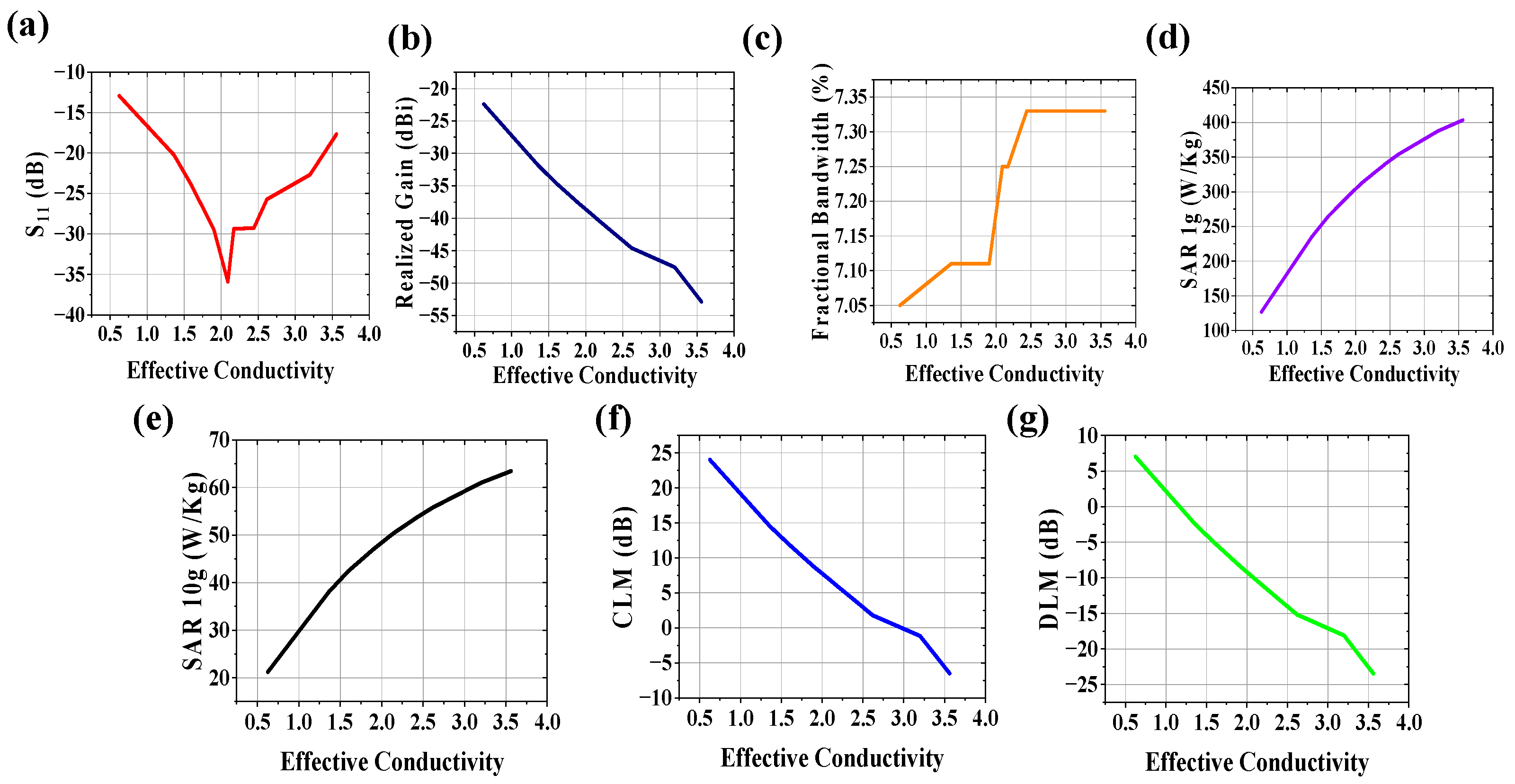
Effect of ±20% variation in effective conductivity on (a) S11, (b) realized gain, (c) fractional bandwidth, (d) 1g SAR (1watt input power) (e) 10g SAR (1 watt input power), (f) CLM (100 kbps data rate at d = 4 m) and (g) DLM (100 kbps data rate at d = 4 m) of implanted antenna system.
Figure 10.
Effect of ±20% variation in effective conductivity on (a) S11, (b) realized gain, (c) fractional bandwidth, (d) 1g SAR (1watt input power) (e) 10g SAR (1 watt input power), (f) CLM (100 kbps data rate at d = 4 m) and (g) DLM (100 kbps data rate at d = 4 m) of implanted antenna system.
3.1. Variation of Effective Relative Permittivity
The communication channel characteristics between implantable antenna system and external receiving antenna connected to monitoring device are varied due to variation in electrical property of human tissues. The effect of effective relative permittivity of body model on radiation performance (S11, realized gain, fractional bandwidth), communication performances (CLM, DLM for 100 kbps data rate at 4 m from implantable antenna system) and SAR profile (SAR for 1g and 10g contiguous tissue) was studied at 2.5 GHz keeping effective conductivity of body model constant at 1.95 S/m and plotted in Figure 9. Due to variation in effective relative permittivity of human body, the return loss is improved for 44.12< ɛeff <55 due to increase in loading on antenna system. Beyond this range, the impedance loading is not taking dominant effect on reflection coefficient of the system as obtained from Figure 9(a). For 44.12< ɛeff <55, variation in realized gain (Figure 9(b)) is almost negligible (~38.4 dBi). However, it is deteriorated towards -41 dBi which also leads to worsen CLM and DLM (refer to Figure 9 (f, g)). Misinterpretation of patient’s data, noisy data acceptance may happen in receiving end. Therefore, doctor cannot monitor and diagnose patient wirelessly in proper way. From Figure 9(c), fractional bandwidth is improved with increase in effective relative permittivity. SAR values for both 1g and 10g tissue (Figure 9(d) and (e) respectively) are not widely dependent on effective relative permittivity variation between 47.45< ɛeff <62.15.
3.2. Variation of Effective Conductivity
The effect of effective conductivity of body model on system performance was studied at 2.5 GHz keeping effective relative permittivity of body model constant at 52.7 and plotted the effects in Figure 10. The increase in conductivity of the wireless communication channel can increase in noise in terms of loss tangent (tan δ) = σeff/ωεeff. From Figure 10 (a), S11 value is improved when σeff is between 1.5 and 3 S/m. Realized gain (Figure 10 (b)), CLM (Figure 10 (f)) and DLM (Figure 10 (g)) are deteriorated with increase in conductivity of human body which hamper the communication performance for Wireless Body Area Network. Analyzing the plot of fractional bandwidth vs effective conductivity shown in Figure 10 (c), it is observed that fractional bandwidth has almost linear relationship with effective conductivity with low slope. SAR values for both 1g and 10g tissue (Figure 10 (d, e) respectively) are highly dependent on effective conductivity variation. SAR values increase in large scale with conductivity increment which may hamper patient safety.
Figure 11.
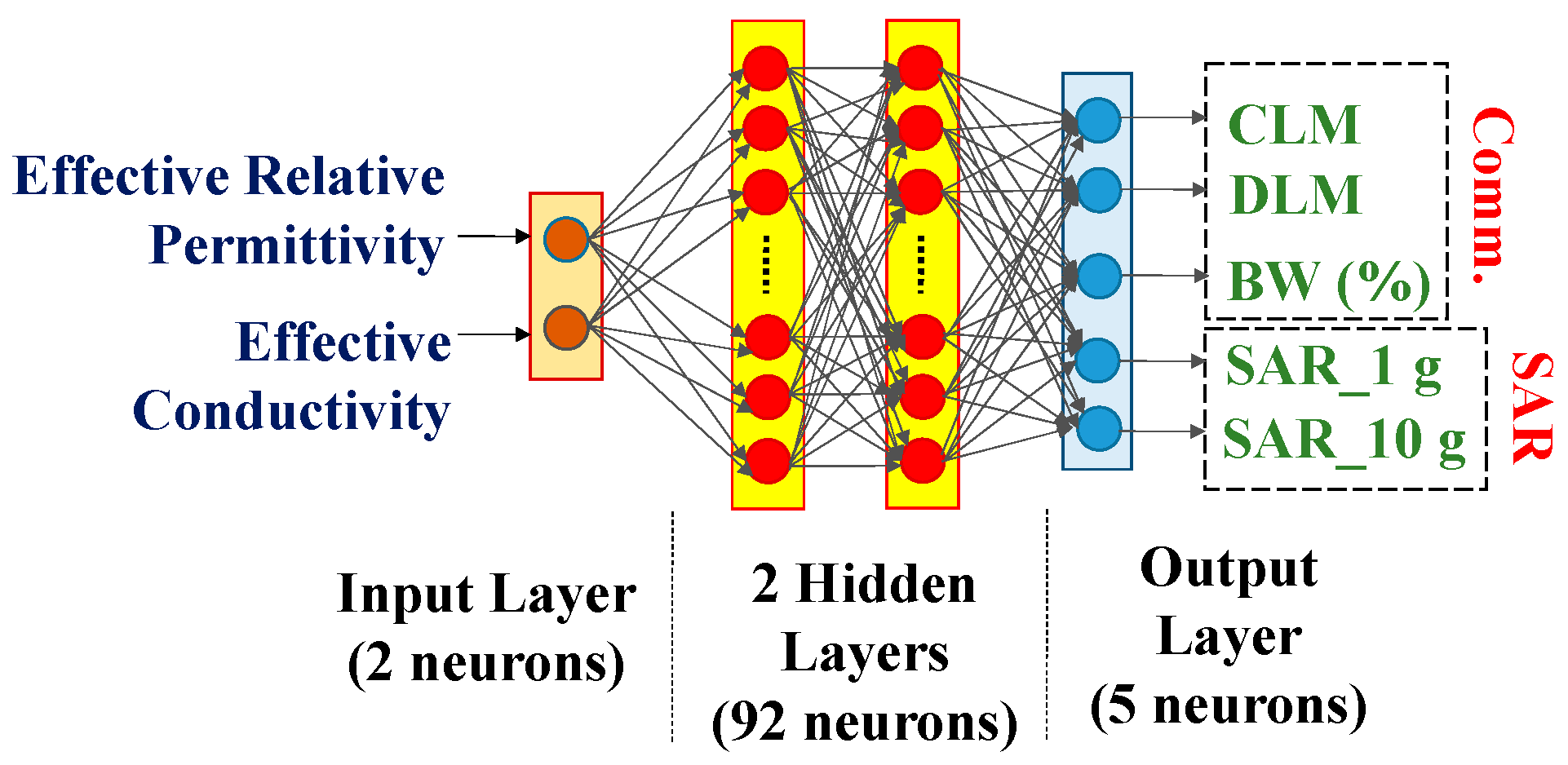
Artificial Neural Network.
3.3. Variations in both Effective Relative Permittivity and Conductivity
Communication characteristics, such as CLM, DLM, include the realized gain and reflection coefficient of implantable antenna system. Therefore only CLM, DLM, SAR for 1g and 10g tissue models and fractional bandwidth are considered for dependence analyses. 2500 scenarios (± 20% variations in reference to effective relative permittivity and conductivity of the human body) were considered here. An artificial neural network (ANN) with two input neurons (ɛeff and σeff) two hidden layers (92 neurons), and five output layers (CLM, DLM, BW (%), SAR_1g and SAR_10g) shown in Figure 11, was trained with 80% of the total scenarios and validated by remaining 20% data. Training time was 2 msec/step. 10 random scenarios were simulated in CST, and simulated responses were collected. The responses of similar scenarios predicted by ANN were recorded to observe the efficiency of prediction by designed ANN. The ANN was modeled to predict the antenna system performance parameter values for any random set of (ɛeff, σeff) because the set values are different for different patients’ bodies.
4. Experimental Setup and Measurement
4.1. Implantable Antenna System
In this section, in-vitro performance analysis of simulated implantable antenna system is described. The physical prototypes of implantable antenna and receiving antenna were fabricated. The fabricated prototype of implantable antenna is shown in Figure 12 (a). Small battery (π X 3.952X 3.6 mm3), prototype of PCB (Arlon AD 430 covered with copper in both sides), prototypes of sensor and camera (Arlon AD 430) were taken to replicate the simulated antenna system as shown in Figure 12(a).To excite the antenna, 50Ω coaxial cable was connected using soldering (Figure 12 (b, c)) and other end was connected with one of the two ports of vector network analyzer (VNA) for S-parameter measurement as illustrated in Figure 12 (d). Top and bottom views of implantable antenna system before coating are shown in Figure 12 (b) and (c) respectively.
The whole system was covered with biocompatible gelatin cover made of 15g DI water and 10g gelatin which is depicted in Figure 12 (e). For in-vitro measurement, homogeneous semi-solid body phantom model was developed by 66.3% DI water, 31.6% DGME, 0.4% NaCl and 1.7% Agar agar powder. The dielectric properties in terms of relative permittivity and conductivity of the phantom were measured using Agilent 85070E dielectric kit. The developed phantom had effective relative permittivity and conductivity of 51.75 and 1.91 S/m respectively at 2.5 GHz. The designed antenna system was then implanted within semi-solid human body phantom at 50 mm depth from top surface as shown in Figure 12 (d) to measure the reflection coefficient of the implanted antenna. The comparison between simulated and measured S11 responses was plotted in Figure 12 (f). The measured S11 was -22.97 dB at 2.43 GHz. The co- and cross-polar E and H plane far field radiation patterns obtained from measurement set up shown in Figure 13 (a-b) are plotted in Figure. 14 (a-d). The antenna system had measured realized gain of -32.68 dBi at its operating frequency.
4.2. Monitoring Antenna
The receiving antenna for monitoring device was fabricated and measured in similar process of reflection coefficient and radiation pattern measurement processes of implantable antenna system. The top view of fabricated Rx antenna along with its comparison plots of reflection coefficient for simulated and measured results is shown in Figure 13 (c). The fabricated antenna had S11 and realized gain of -20.18 dB and 4.02 dBi. For communication performance study, Rx antenna was kept at different distances (d) from implantable antenna as shown in Figure 13 (d) and study CLM, DLM and gain from transmission coefficient measurements.
Table 4.
Comparison of Estimated Responses of ANN with Simulated and Measured Results.
4.3. Variation Analysis
These scenarios were replicated in a laboratory by varying the amount of DGME with 273 ml DI water and 794 mg NaCl. The practical antenna parameters within 10 prepared phantoms were collected by putting fabricated antenna inside them. Table 4 and Table 5 show the effective predictions of communication performance and SAR profile by ANN due to the variable human body model, respectively. From Table 4 and Table 5, it is observed that the designed antenna could predict the communication performance of the implanted antenna with a respective average accuracy of 99.89% and 99.78% with respect to simulation and measurement for ±20% possible variations in both electrical properties. Respective average accuracies of implantable antenna of 99.01% and 98.27% for 1 g and 10 g SAR profiles were observed. Compared with the reference effective electrical properties of the homogeneous human body model, respective maximum variations of 63%, 41.6%, 17.97%, 26.79% and 5.89% are observed in 1 g and 10 g SAR value, fractional bandwidth, CLM and DLM at 4 m distance for 100 Kbps.
5. Conclusions
In this study, the dependences of communication performance and SAR profile variations of a corner-chamfered meander-line body-implantable antenna at 2.5 GHz on effective relative permittivity and conductivity were numerically analyzed. An ANN with two input variables (ɛeff, σeff) and five output variables (SAR_1g, SAR_10g, fractional bandwidth, CLM and DLM) is trained by 80% and tested by 20% of total scenarios for accurate dependence analysis. Compared with the reference effective electrical properties of the homogeneous human body model, respective maximum variations of 63%, 41.6%, 17.97%, 26.79% and 5.89% were observed in 1 g and 10 g SAR value, fractional bandwidth, CLM and DLM at 4 m distance for 100 Kbps. Designed ANN can predict the communication performance of implanted antenna with respective average accuracy of 99.89% and 99.78% with respect to simulation and measurement for ±20% possible variation in both electrical properties. Respective average accuracies of implantable antenna 99.01% and 98.27% for 1 g and 10 g SAR profiles are observed.
Author Contributions
Conceptualization, Soham Ghosh; Formal analysis, Fanuel Elias and Bhaskar Gupta; Funding acquisition, Stephen Alabi; Investigation, Soham Ghosh; Methodology, Soham Ghosh, Sunday Ekpo, Fanuel Elias and Bhaskar Gupta; Software, Soham Ghosh; Supervision, Sunday Ekpo and Bhaskar Gupta; Validation, Soham Ghosh, Sunday Ekpo and Bhaskar Gupta; Writing – original draft, Soham Ghosh; Writing – review & editing, Sunday Ekpo, Fanuel Elias and Stephen Alabi.
Funding
This research received no funding.
Institutional Review Board Statement
Not applicable.
Informed Consent Statement
Not applicable.
Data Availability Statement
The original contributions presented in this study are included in the article/supplementary material. Further inquiries can be directed to the corresponding author(s).
Conflicts of Interest
The authors declare no conflicts of interest.
References
- Singh, M. S.; Ghosh, J.; Ghosh, S.; and Sarkhel, A. Miniaturized Dual-Antenna System for Implantable Biotelemetry Application. IEEE Antennas and Wireless Propagation Letters. 2021, 20(8), 1394-1398. [CrossRef]
- Dixon, A. M. R.; Allstot, E. G.; Gangopadhyay, D.; and Allstot, D. J. Compressed Sensing System Considerations for ECG and EMG Wireless Biosensors. IEEE Transactions on Biomedical Circuits and System. 2012, 6(2), 156-166. [CrossRef]
- Kiourti, A.; and Nikita, K. S. Numerical Assessment of the Performance of a Scalp-Implantable Antenna: Effects of Head Anatomy and Dielectric Parameters. Bioelectromagnetics, 2012, 34(3). [CrossRef]
- Kim, J.; and Rahmat-Samii, Y.; Implanted antennas inside a human body: simulations, designs, and characterizations. IEEE Transactions on Microwave Theory and Techniques. 2004, 52(8), pp. 1934-1943. [CrossRef]
- Hayat, S.; Shah, S. A. A.; and Yoo, H.; Miniaturized Dual-Band Circularly Polarized Implantable Antenna for Capsule Endoscopic System. IEEE Transactions on Antennas and Propagation. 2021, 69(4), 1885-1895. [CrossRef]
- Crumley, G. C.; Evans, N. E.; Burns, J. B.; and Trouton, T. G. On the design and assessment of a 2.45 GHz radio telecommand system for remote patient monitoring. Medical Engineering & Physics. 1999, 20(10), 750-55. [CrossRef]
- McIntosh, R. L.; Iskra, S.; McKenzie, R. J.; Chambers, J;. Metzenthen, B.; and Anderson, V. Assessment of SAR and thermal changes near a cochlear implant system for mobile phone type exposures. Bioelectromagnetics, 2007, 29(1), pp. 71-80. [CrossRef]
- Ghosh, S.; Kundu, A.; and Gupta, B.; Slot based Miniaturized Human Body Implantable Antenna Design at 2.45 GHz ISM Band. In 2022 IEEE Wireless Antenna and Microwave Symposium, Rourkela, India, 2022, pp. 1-5. [CrossRef]
- Yeap, K.; Voon, C.; Hiraguri, T.; and Nisar, H. A compact dual-band implantable antenna for medical telemetry. Microwave Optical Technology Letters. 2019, 61(9). [CrossRef]
- Karacolak, T.; Hood, A. Z.; and Topsakal, E. Design of a Dual – Band Implantable Antenna and Development of Skin Mimicking Gels for Continuous Glucose Monitoring. IEEE Transactions on Microwave theory and Techniques, 2008, 56(4). [CrossRef]
- Yilmaz, T.; Karacolak, T.; and Topsakal, E. Characterization and Testing of a Skin Mimicking Material for Implantable Antennas Operating at ISM Band (2.4 GHz – 2.48 GHz). IEEE Antennas and Wireless Propagation Letters, 2008, 7, 418 – 420. [CrossRef]
- Zada, M. and Yoo, H. A Miniaturized Triple – Band Implantable Antenna System for Bio -Telemetry Applications. IEEE Transactions on Antennas and Propagation, 2018, 66(12), 7378 – 7382. [CrossRef]
- ICNIRP. Guidelines for limiting exposure to electromagnetic fields (100 KHz to 300 GHz). Health Phys. 2020, 118(5), 483-524.
- Cleveland, R. F., Jr.; Sylvar, D. M;. and Ulcek, J. L. Evaluating compliance with FCC guidelines for human exposure to radiofrequency electromagnetic fields. FCC OET Bulletin. 1997, 65(97-01), Washington D.C.
- Department of Telecommunication (DoT). A Journey for EMF. 2012, www.dot.gov.in/journey-emf.
- Le, T. T.; Kim, Y. -D.; and Yun, T. -Y. A Triple-Band Dual-Open-Ring High-Gain High-Efficiency Antenna for Wearable Applications. IEEE Access. 2021, 9, 118435-118442. [CrossRef]
- Fear, E. C.; Meaney, P. M.; and Stuchly, M. A. Microwaves for breast cancer detection? IEEE Potentials. 2003, 22(1), 12-18. [CrossRef]
- Yousef, H., Alhajj, M., Sharma, S. Anatomy, Skin (Integument), Epidermis. StatPearls [Internet], 2023.
- Markova, M. S., Zeskand, J., McEntee, B., Rothstein, J., Jimenez, S. A., Siracusa, L. D. A role for the androgen receptor in collagen content of the skin. J Invest Dermatol. 2004, 123, 1052-1056. [CrossRef]
- Kopera, D. Impact of Testosterone on Hair and Skin. Endocrinology& Metabolic Syndrome, 2015. 4(3), 2015.
- Wang, X., Xu, M., Li, Y. Adipose Tissue Aging and Metabolic Disorder, and the impact of Nutritional Inventions. Nutrients. 2022, 14. [CrossRef]
- Walia, N. S., Raj, R., and Tak, C. S. Gottron’s syndrome. Indian Journal of Dermatology, Venereology and Leprosy. 2001, 67.
- Szewc, M., Sitarz, R., Moroz, N., Maciejewski, R. and Wierzbicki, R. Madelung’s disease – progressive, excessive, and symmetrical deposition of adipose tissue in the subcutaneous layer: case report and literature review. Diabetes, Metabolic Syndrome and Obesity: Targets and Therapy. 2018, 11, 819-825. [CrossRef]
- Ghodgaonkar, D. K.; Gandhi, O. P.; and Iskander, M. F. Complex permittivity of human skin in vivo in the frequency band 26.5-60 GHz. IEEE Antennas and Propagation Society International Symposium. Transmitting Waves of Progress to the Next Millennium. 2000 Digest. Held in conjunction with: USNC/URSI National Radio Science Meeting (C, Salt Lake City, UT, USA, 2000, 2, 1100-1103.
- Hwang, H.; Yim, J.; Cho, J.-W.; Cheon, C.; and Kwon, Y. 110 GHz broadband measurement of permittivity on human epidermis using 1 mm coaxial probe. In IEEE MTT-S International Microwave Symposium Digest, 2003, Philadelphia, PA, USA, 1, 399-402.
- Boric-Lubecke, O.; Nikawa, Y.; Snyder, W.; Lin, J.; and K. Mizuno, Novel microwave and millimeter-wave biomedical applications. In 4th International Conference on Telecommunications in Modern Satellite, Cable and Broadcasting Services. TELSIKS'99 (Cat. No.99EX365), Nis, Yugoslavia, 1999, 186-193.
- Peyman, A.; Kos, B.; Djokic, M.; Trotovsek, B.; L.-Stokin, C.; Sersa, G.; and Miklavcic, D. Variation in Dielectric Properties Due to Pathological Changes in Human Liver. Bioelectromagnetics. 2015. 36,603-612. [CrossRef]
- Johnson, J. Statistical analysis of detuning effects for implantable microstrip antennas. Ph.D. Thesis, University of Utah, 2007.
- Vidal, N.; Curto, S.; Lopez Villegas, J. M.; Sieiro, J.; and Ramos, F. M. Detuning study of implantable antennas inside the human body. Progress in Electromagnetics Research. 2012. 124, 265-283. [CrossRef]
- Ekpo, S. C.; and George, D. Impact of Noise Figure on a Satellite Link Performance. IEEE Communications Letters. 2011, 15(9), 977-979. [CrossRef]
- Ekpo, S. C. Parametric System Engineering Analysis of Capability-Based Small Satellite Missions. IEEE Systems Journal. 2019, 13, (3), 3546-3555. [CrossRef]
- Jing, D.; Li, H.; Ding, X.; Shao, W.; and Xiao, S. Compact and Broadband Circularly Polarized Implantable Antenna for Wireless Implantable Medical Devices. IEEE Antennas and Wireless Propagation Letters. 2023, 22(6), 1236-1240. [CrossRef]
- Fang, X.; Du, X.; Bärhold, M.; Wang, Q.; and Plettemeier, D. MICS-Band Helical Dipole Antenna for Biomedical Implants. IEEE Antennas and Wireless Propagation Letters. 2022, 21(12), 2502-2506. [CrossRef]
- Ali, R.; Cho, Y.; Shah, I. A.; Hayat, S.; Basir, A.; and Yoo, H. Compact Dual-Band MIMO Implantable Antenna System for High-Data-Rate Cortical Visual Prostheses Applications. IEEE Transactions on Antennas and Propagation. 2024, 72(8), 6374-6386. [CrossRef]
- Ashvanth, B.; and Partibane, B. Miniaturized dual wideband MIMO antenna for implantable biomedical applications. Microw. Opt. Technol. Lett.. 2023, 65(12), 3296–3302.
- Iqbal, A.; Al-Hasan, M.; Mabrouk, I. B.; and Denidni, T. A.; Deep-Implanted MIMO Antenna Sensor for Implantable Medical Devices. IEEE Sensors Journal. 2023, 23(3), 2105-2112. [CrossRef]
- Iqbal, A.; Sura, P. R.; Smida, A.; Al-Hasan, M.; Ben Mabrouk, I.; and Denidni, T. A. Dual-Band 3-D Implantable MIMO Antenna for IoT-Enabled Wireless Capsule Endoscopy. IEEE Internet of Things Journal. 2024, 11(19), 31385-31393. [CrossRef]
- Vidal, N.; Garcia-Miquel, A.; Lopez-Villegas, J. M.; Sieiro, J. J. and Ramos, F. M. Influence of phantom models on implantable antenna performance for biomedical applications. In 2015 9th European Conference on Antennas and Propagation (EuCAP), Lisbon, Portugal, 2015, 1-4..
- Perez, M. D.; Jeong, S. H.; Raman, S.; Nowinski, D.; Wu, Z.; Redzwan, S.; Velander, J.; Peng, Z.; Hjort, K.; and Augustine, R. Head-compliant microstrip split ring resonator for noninvasive healing monitoring after craniosynostosis-based surgery. Healthcare Technology Letters. 2020, 7(1), 29-34. [CrossRef]
- Patra, K. Analytical Modelling of Microstrip Travelling Wave Antennas. PhD Dissertation. Electronics and Tele-Communication Engineering, Jadavpur University, India, 2018.
- IEEE Standard for Safety Levels with Respect to Human Exposure to Electric, Magnetic, and Electromagnetic Fields, 0 Hz to 300 GHz – Redline. IEEE Std C95.1-2019 (Revision of IEEE Std C95.1-2005/ Incorporates IEEE Std C95.1-2019/Cor 1-2019) – Redline. 2019, 1-679, 4.
Short Biography of Authors
 |
SOHAM GHOSH was born in Kolkata, India, in 1997. He received the B. Tech degree in Electronics and Communication Engineering from Academy of Technology affiliated to Maulana Abul Kalam Azad University of Technology, Kolkata, India in 2019 and M.E. degree in Electronics and Telecommunication Engineering from Jadavpur University, Kolkata, India in 2022. He is currently pursuing Ph. D. degree from the Faculty of Engineering and Technology, Jadavpur University, India since 2022. His research interests include electromagnetic theory, implantable antenna design and communication, mathematical modeling of antenna, 5G antennas, Terahertz antennas etc. He has authored three conference papers and coauthored five conference papers published in IEEE. He has authored three journal papers and coauthored two journal papers published in different journals. He is a member of IEEE Microwave Theory and Techniques- Student Branch Chapter, Jadavpur University under Kolkata Section, India. He received University Gold medal from Jadavpur University, India in 2022. He received “Best Student Paper Award” in the conference IEEE Wireless Antenna and Microwave Symposium in 2022. |
 |
SUNDAY C. EKPO obtained the MSc. Degree in Communication Engineering from the University of Manchester, Manchester, U.K. in September 2008 and proceeded for his PhD degree in Electrical and Electronic Engineering at the same institution. He holds a PGC. in Academic Practice; MA. in Higher Education; Chartered Engineer; and Senior Fellow of the Higher Education Academy, UK. He is a Chartered Engineer (CEng) with experience of carrying out world-leading fundamental, use-inspired and applied research projects on sustainable radio communication and satellite systems engineering. He designs reconfigurable / digitally-assisted architectures to achieve ultra-low energy and spectrum-efficient multi-radio multi-coverage/range solutions/ internet of things products. He is a Senior Lecturer in Electrical and Electronic Engineering, Manchester Metropolitan University, UK; leads the Communication and Space Systems Engineering research team. He is a British Council Stakeholder for the Innovation for African Universities Projects and Community of Practice. His research work spans 120+ peer-reviewed and refereed technical publications and attracted £1.5m+ grants income. He is a recipient of the Huawei's Influential Thinkers in Engineering and Technology Recognition 2019, and member of the UK Research and Innovation Talent Panel College; Engineering and Physical Sciences Research Council Peer Review College; Institution of Engineering and Technology, UK; internationally recognized R&D leader in Advanced Manufacturing of Electronics; American Institute of Aeronautics and Astronautics Member of the Association of International Education Administrators, USA; Carbon Literacy Champion for the Electrical & Electronic Engineering program; and Principal Investigator of the Sony’s Sensing Solutions University Program. |
 |
FANUEL ELIAS is an accomplished Electrical and Electronics Engineering researcher who received his first-class BEng Degree in Electrical and Electronics Engineering from the Manchester Metropolitan University, UK, in 2023. He is pursuing a PhD in RF Engineering and specializes in Reconfigurable Holographic Multi-Radio Metasurface Rectennas for Ultra-low Power 5G/Wi-Fi 6/6E/7/Hallow Applications. His award-winning final year project focused on Reconfigurable Wireless WI-FI6/6E/7/5G Energy Harvesting Design. He's also a research assistant for the Royal Academy of Engineering, contributing to Premenstrual Dysphoric Disorder (PMDD) sensors. His expertise encompasses RF engineering, including subsystem design, rectifiers, antenna design, and RF transceiver characterization. His research interests lie in metamaterial and metasurface analysis, specifically emphasizing energy harvesting and antenna applications, driving innovation in wireless communication technology. He served on the technical programme committee for the Second International Adaptive and Sustainable Science, Engineering and Technology (ASSET) Conference 2023 and as Publicity Chair for the Third ASSET Conference 2024, both held in Manchester, UK. |
 |
STEPHEN ALABI holds a BSc in Engineering Physics and a MSc in Advanced Process Design for Energy from The University of Manchester, UK. He currently leads the R&D of passive, hybrid and active energy-efficient and ultra-low-carbon internet of things sensors electronics innovations using advanced nanoscale integrated manufacturing technology for the global net zero attainment. He is the Founder and Managing Director of SmOp CleanTech and has overall responsibility for its operational performance. Stephen is also the driving force behind SmOp’s strategic plan. His background is in the scientific aspects of the Company’s project which has aided products delivery and knowledge transfer. His involvement in setting the strategic direction of the business and authority to commit resources to support Research and development projects make him the ideal candidate to act as Senior Business Employee. He was the Technical Programme Chair at the Second International Adaptive and Sustainable Science, Engineering and Technology (ASSET) Conference 2023 held in Manchester, UK and gave Keynote Speeches on “Hybrid Wireless Power Transfer for Passive Electronic Appliances” (ASSET 2023); and “Advanced Manufacturing of Electronics for Green Energy Harvesting Use Cases and Applications” (ASSET 2024). SmOp CleanTech was the Diamond Sponsor of the ASSET Conference and He is an Executive Stakeholder of the ASSET Council has 10 peer-reviewed and refereed technical publications and 10+ peer-reviewed articles on “green energy development for future-generations telecoms infrastructure” in-preparation. Under Stephen’s R&D engineering leadership, SmOp has developed intellectual properties and patentable green radio frequency communication and low-carbon hybrid RF-solar energy harvesting products for different horizontal and vertical use cases spanning civil and commercial applications for the major industries/sectors. |
 |
BHASKAR GUPTA was born in Kolkata, India, in 1960. He received the B.E.Tel.E., M.E.Tel.E., and Ph.D. (Eng.) degrees from Jadavpur University, Kolkata, in 1982, 1984 and 1996, respectively. He is Ex-Vice Chancellor at Jadavpur University, Kolkata, India where he has been teaching since 1985. He has published numerous research articles in refereed journals and conferences and co-authored three books of advanced research topics. He is a Senior Member of IEEE, Fellow of IETE, Fellow of Institution of Engineers (India), and Life Member of SEMCE (I). He was the Chairman of WB Centre, ET division of IE(I) and Vice Chair, IEEE Kolkata Section. He served as referee, Associate Editor and Guest Editor in different internationally acclaimed journals. His present area of interest is Planar Antennas, Implantable and Wearable Antennas etc. in Microwave Engineering and Antennas. He has published about 200 research articles in refereed journals including IEEE journals and conferences and coauthored two books on advanced research topics, published internationally. |
Figure 1.
Overview of a wireless communication link between an implantable antenna system and an external health monitoring device.
Figure 1.
Overview of a wireless communication link between an implantable antenna system and an external health monitoring device.
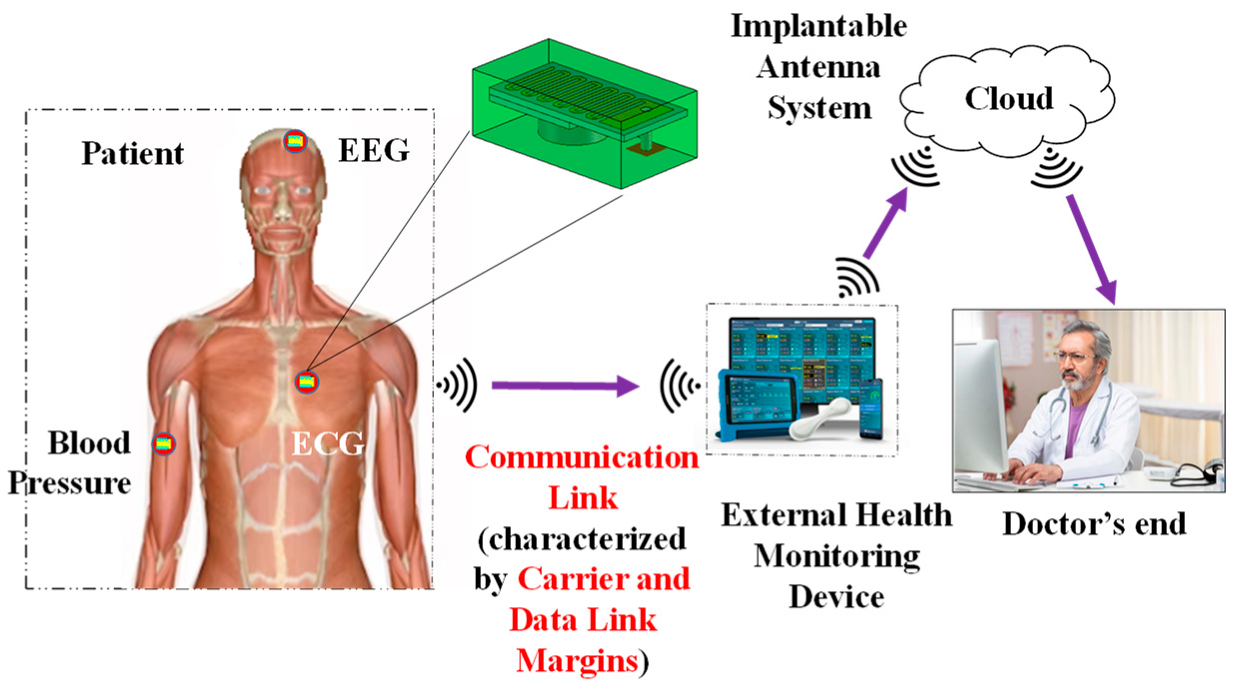
Figure 3.
Detailed architecture of Implantable device: (a) Top view, (b) Bottom view, (c) Isometric view and (d) Exploded view.
Figure 3.
Detailed architecture of Implantable device: (a) Top view, (b) Bottom view, (c) Isometric view and (d) Exploded view.
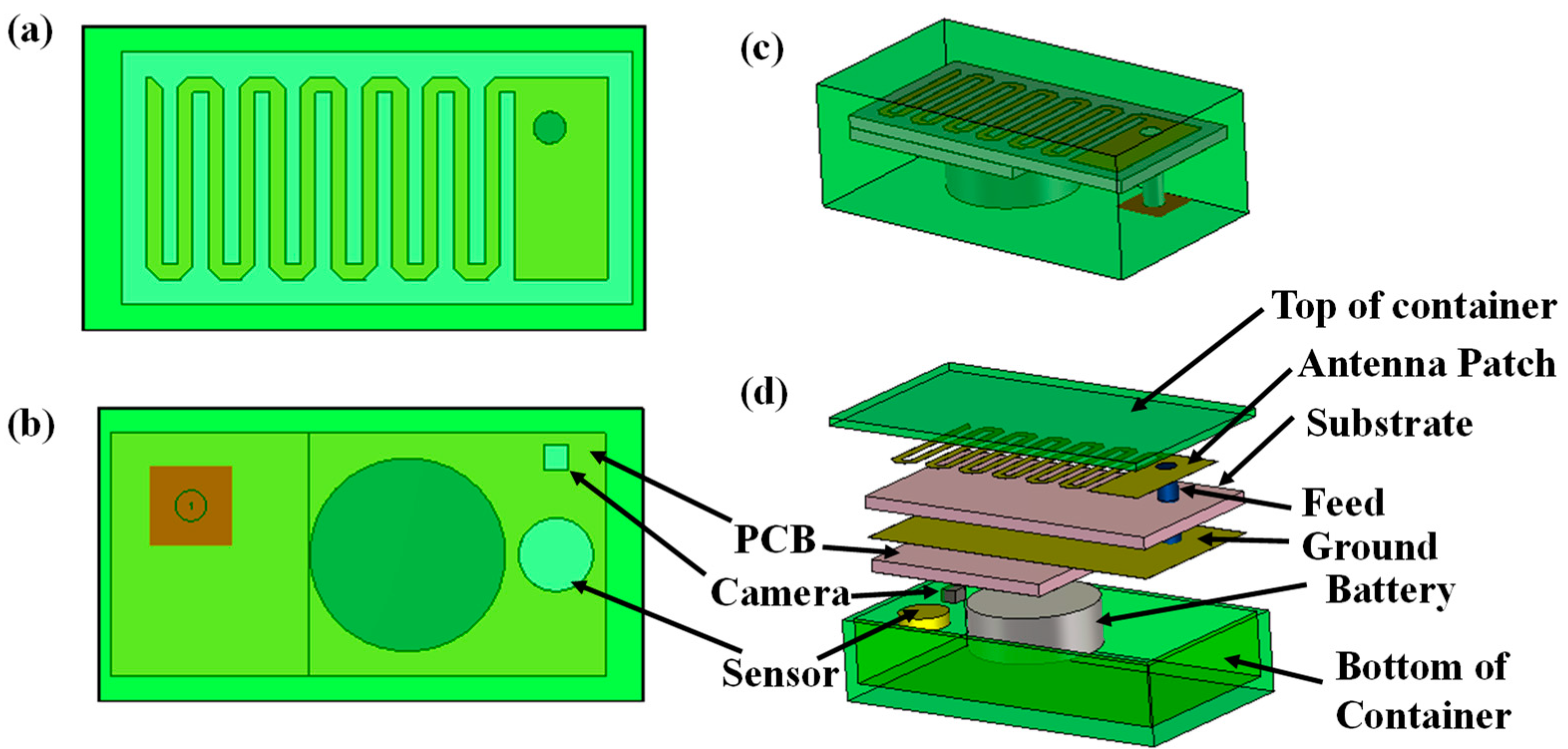
Figure 4.
Homogeneous human body model consider to simulate implantable antenna system.
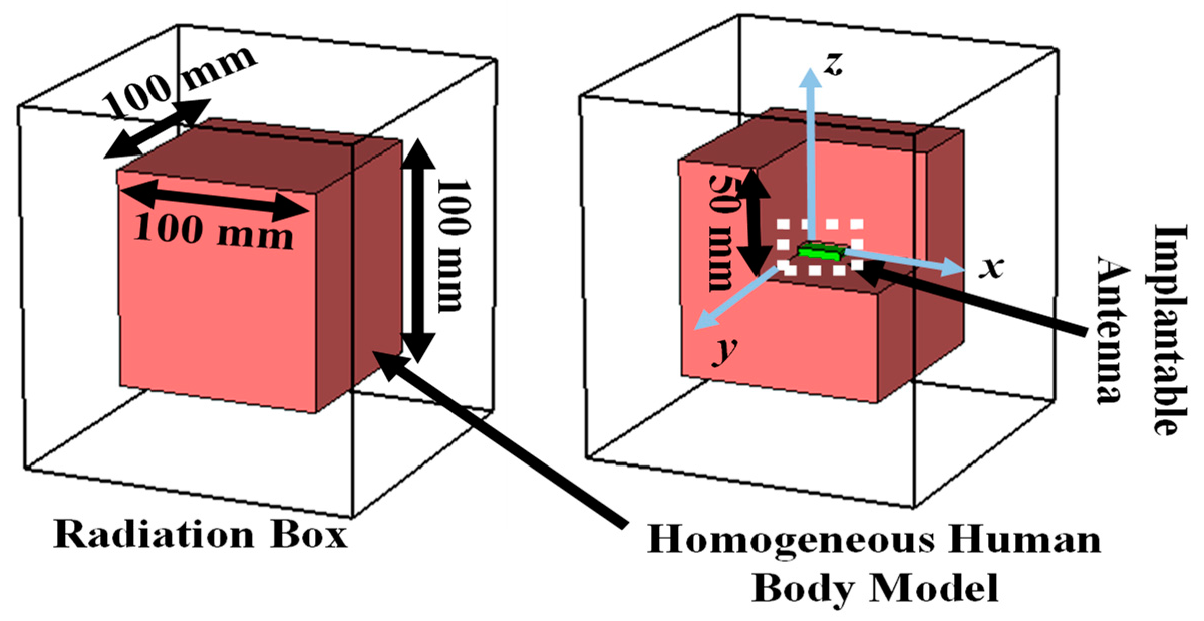
Figure 8.
(a) Simulation setup for calculating link margin, (b) generalized link margin vs distance between implanted antenna system and receiving antenna and (c) CLM and DLM vs distance.
Figure 8.
(a) Simulation setup for calculating link margin, (b) generalized link margin vs distance between implanted antenna system and receiving antenna and (c) CLM and DLM vs distance.
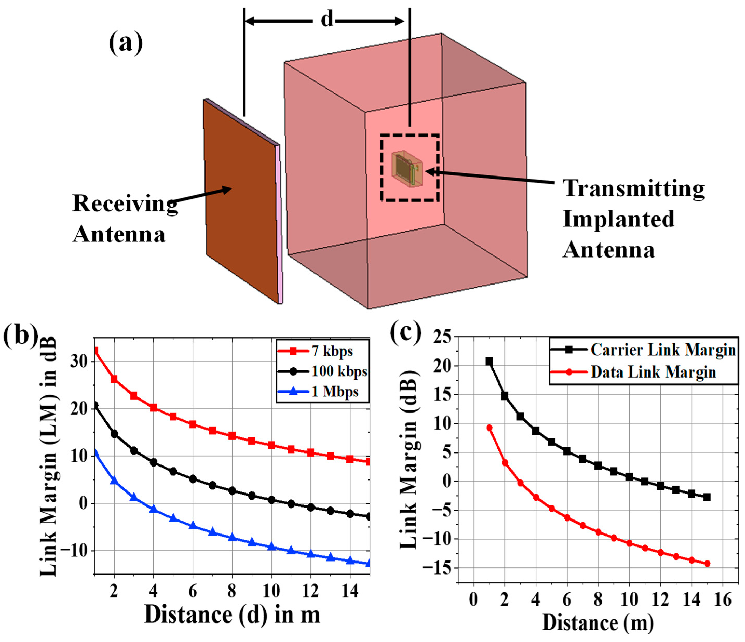
Figure 12.
(a) Fabricated prototypes of all components of the implantable antenna system, (b) top and (c) bottom views of implantable antenna system without cover, (d) reflection coefficient measurement setup of implantable antenna, (e) top view of antenna system within gelatin coating and (f) comparison between simulated and measurement.
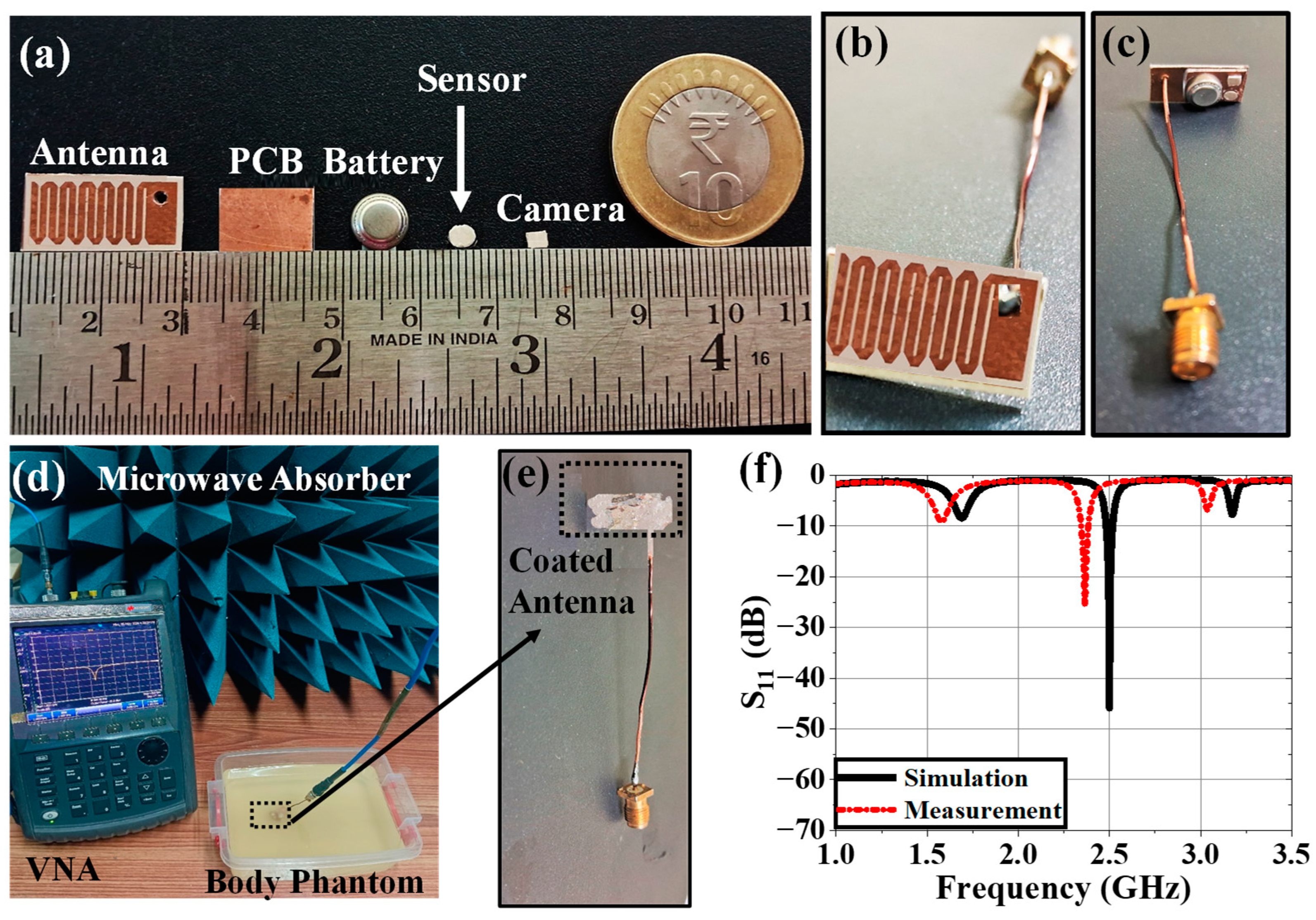
Figure 13.
(a) Schematic of far-field radiation pattern measurement setup within anechoic chamber and its required hardware, (b) Far-field radiation pattern measurement of implantable antenna system within phantom using a TEM horn antenna, (c) top view of fabricated receiving antenna and its reflection coefficient plots (comparison between simulation and measurement), (d) communication performance between Tx implantable antenna system and Rx antenna.
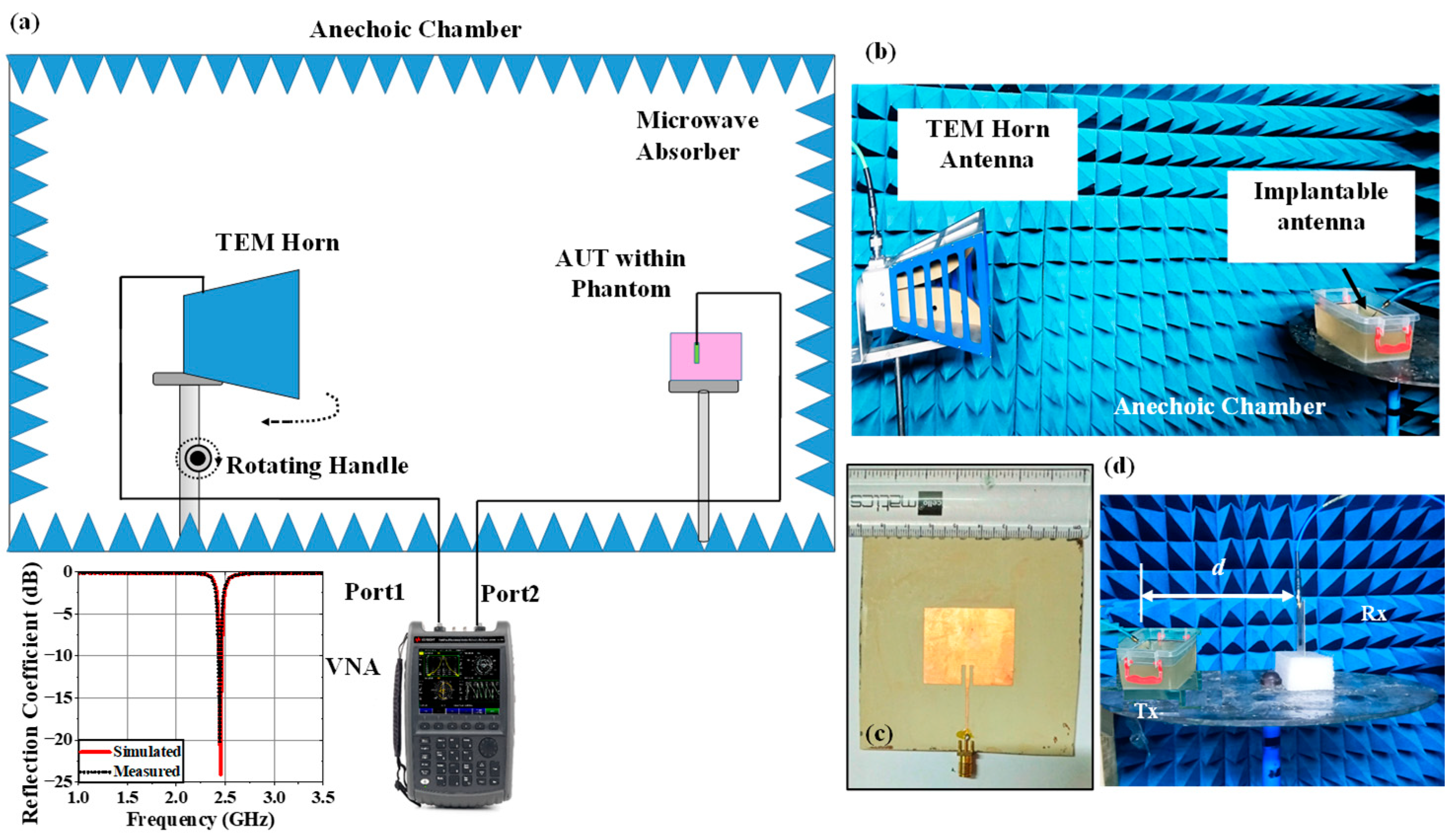
Figure 14.
Comparison of radiation patterns between simulated and measured responses at (a) E-plane co-polar, (b) E-plane cross polar, (c) H-plane co-polar and (d) H-plane cross polar at 2.5 GHz.
Figure 14.
Comparison of radiation patterns between simulated and measured responses at (a) E-plane co-polar, (b) E-plane cross polar, (c) H-plane co-polar and (d) H-plane cross polar at 2.5 GHz.
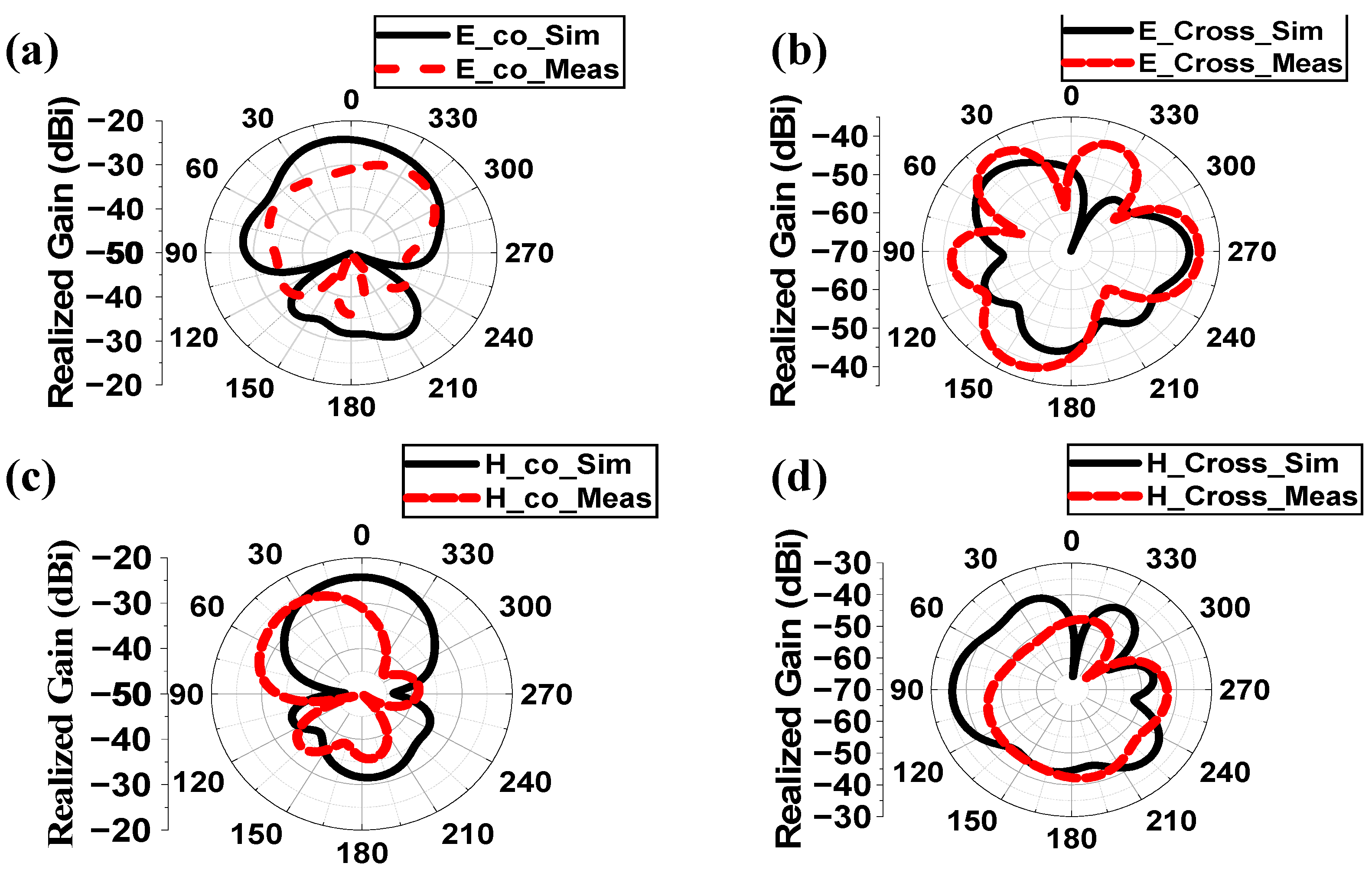
Table 1.
Comparison with Previously Reported Works.
| Ref. | Freq. (GHz) | S11 (dB) |
Gain (dBi) | SAR_1g (1W) (W/Kg) | CLM (dB) | DLM (dB) | Comm. range (m) | Uncertain Parameters | Samples | Variation Analysis Techniques | Variation in parameters Tested |
|---|---|---|---|---|---|---|---|---|---|---|---|
| [32] | 2.4 | -25 | -24.7 | 697.5 | No | No | 17 (7kbps), 4.3 (100 kbps) and 1.4 (1 Mbps) |
No | No | No | No |
| [33] | 0.4 | -20 | -18.9 | No | No | No | No | No | No | No | No |
| [34] | 0.915, 2.45 | -25, -40 |
-30.47, -24.71 |
658, 589 | No | No | 2 | No | No | No | No |
| [35] | 0.915, 2.45 | -20, -37 |
-36, -30.1 |
333 | No | No | No | No | No | No | No |
| [36] | 0.915 | -20 | -23.23 | 270.3 | No | No | 13 | Effective permittivity | 6 | Cartesian plot | Sensing Performance |
| [37] | 0.915, 2.45 | -19, -15 |
-26.30, -20.9 |
306.19, 252.36 | No | No | 8 | No | No | No | No |
| [38] | 0.402, 2.45 | No | -37, -24.5 |
No | No | No | No | Phantom Size | 2 | Cartesian plot | Gain, efficiency |
| [39] | 2.45 | -11 | No | No | No | No | No | Relative Permittivity | 6 | Cartesian plot | S11 and frequency |
| This Work | 2.5 | -45.9 | -38.42 | 220.26 |
20.73 (d = 1m, Ts =13K) (First) |
9.28 (d = 1m, Ts =13K) (First) |
15 (7kbps), 10 (100 kbps) and 3.5 (1 Mbps) |
Effective permittivity and Conductivity | 2500 |
ANN modeling (First) |
CLM, DLM, bandwidth and SAR performance (First) |
Table 5.
Comparison of SAR Profile Predicted By ANN with Simulated Results.
| Sample | Effective Properties | Simulation | ANN | % error of prediction w.r.t Simulation | ||||
|---|---|---|---|---|---|---|---|---|
| ɛeff | σeff | 1 g | 10 g | 1 g | 10 g | 1 g | 10 g | |
| 1 | 46.02 | 0.63 | 250.15 | 65.09 | 247.60 | 64.98 | 1.03 | 0.17 |
| 2 | 46.02 | 0.92 | 147.78 | 43.57 | 145.98 | 42.65 | 1.23 | 2.16 |
| 3 | 46.02 | 3.56 | 302.63 | 74.26 | 300.98 | 75.95 | 0.55 | 2.23 |
| 4 | 49.80 | 1.80 | 227.38 | 61.01 | 227.22 | 61.42 | 0.07 | 0.67 |
| 5 | 51.69 | 1.51 | 203.46 | 56.43 | 202.65 | 57.23 | 0.40 | 1.40 |
| 6 | 53.59 | 1.80 | 225.20 | 60.72 | 226.18 | 60.55 | 0.43 | 0.28 |
| 7 | 55.48 | 2.10 | 348.30 | 64.03 | 345.45 | 65.22 | 0.83 | 1.82 |
| 8 | 57.37 | 0.63 | 109.15 | 33.91 | 108.45 | 33.22 | 0.65 | 2.08 |
| 9 | 59.26 | 0.92 | 127.85 | 42.47 | 125.65 | 42.58 | 1.75 | 0.26 |
| 10 | 63.04 | 2.97 | 231.16 | 68.81 | 235.22 | 69.18 | 1.73 | 0.53 |
Disclaimer/Publisher’s Note: The statements, opinions and data contained in all publications are solely those of the individual author(s) and contributor(s) and not of MDPI and/or the editor(s). MDPI and/or the editor(s) disclaim responsibility for any injury to people or property resulting from any ideas, methods, instructions or products referred to in the content. |
© 2025 by the authors. Licensee MDPI, Basel, Switzerland. This article is an open access article distributed under the terms and conditions of the Creative Commons Attribution (CC BY) license (http://creativecommons.org/licenses/by/4.0/).
Copyright: This open access article is published under a Creative Commons CC BY 4.0 license, which permit the free download, distribution, and reuse, provided that the author and preprint are cited in any reuse.


