Submitted:
09 February 2026
Posted:
10 February 2026
You are already at the latest version
Abstract
High-performance difference patterns (DPs) are critical for compact and inte-grated microwave array systems, particularly in monopulse tracking and beam-scanning applications. However, the design of monopulse phased arrays with steep slopes, high directivity, low sidelobes, and symmetric main lobes remains challenging due to con-straints imposed by the array aperture and radome structure. In this paper, a novel design method is proposed to maximize the DP directivities for monopulse linear and planar phased arrays composed of microstrip patch antennas. The DP synthesis problem is first formulated as a nonconvex optimization model for directivity maximization. By fixing the reference phase of the DP slope and applying a first-order Taylor expansion of the quad-ratic function, the original problem is decomposed into a sequence of convex subproblems that can be solved efficiently. The proposed method fully exploits the flexibility of the phased array feed network, enabling directivity enhancement without altering the geo-metric configuration of the monopulse array. Finally, two numerical examples employing a radome-enclosed linear phased array and a uniform planar phased array are presented to demonstrate effectiveness of the proposed method in achieving the monopluse array DP synthesis with high directivity and symmetric main-lobes.
Keywords:
difference pattern (DP)
; directivity maximization
; monopulse array
; microstrip patch antenna
; radome-enclosed linear phased array
; planar phased array
; low sidelobes
1. Introduction
Antenna arrays with sum and difference patterns (SDPs) are widely employed in various radar and guidance systems for target detection and tracking. In a typical monopulse architecture, the target angular and distance information is obtained by comparing the SDP signals. A difference pattern (DP) is applied to detect the direction of the target. Consequently, a low sidelobe level (SLL) DP with large slope in the target direction is desired to enhance the tracking accuracy.
Many efficient DP synthesis techniques have been proposed, including numerical analysis methods, global optimization algorithms, convex optimization methods, and alternating projection techniques. Classical Bayliss method and its extensions were proposed in [3,4,5,6] to synthesize low SLL DPs for linear and planar arrays. Although these methods are computationally efficient and straightforward to implement, they are only applicable to uniform arrays composed of ideal isotropic point sources. With the development of computer technology, different kinds of global optimization algorithms [7,8,9,10,11,12,13], such as genetic algorithms [7,8], differential evolution algorithms [9,10], and particle swarm optimization methods [11], have been extensively applied to solve the DP synthesis problems. These global optimization methods are not limited by the array geometry and can obtain good results, but these algorithms may trap into local optimal solution, and the optimization process takes a relatively long time with the increase of the variable dimension. As an efficient global optimization framework, convex optimization approach has also been widely adopted for the DP syntheses in various array configurations. In 2005, Bucci et al. first proposed a new approach based convex optimization that can obtain the low SLL DPs of an arbitrary arrays with a given geometry by solving a convex optimization problem [14]. Two polarization-controlled DP synthesis methods were developed in [15,16], where the polarization and power pattern constraints were jointly converted into convex constraints. These approaches can synthesize the DPs for the circularly polarized linear arrays, the elliptically polarized circular-arc arrays, as well as the broadband polarization-controlled arrays. In 2014, the semidefinite relaxation techniques were used to simultaneously synthesize the SDPs [17], in which part excitation coefficients of the SDP were shared. However, an approximate eigenvalue decomposition is required in this approach [17] to recover the excitations, which may lead to performance degradation of the optimized radiation patterns. An iterative convex optimization method was proposed in [18] for the DP synthesis of asymmetric-aperture conformal arrays. In addition, the alternating direction method of multipliers were employed in [19,20] for the synthesis of low SLL SDPs. Nevertheless, the aforementioned methods primarily focus on sidelobe suppression and polarization control of the DPs, and directivity optimization of the array DP has not yet been addressed.
Directivity, as another important performance index of antenna arrays, has also attracted considerable attention. In 2019, Lei et al. formulated the wide-beam array synthesis as a power-gain optimization problem and employed the convex optimization to achieve the minimum-gain maximization in [21], and further extended the framework in [22] by incorporating the dynamic range ratio constraints via the iterative convex approximation, enabling practical wide-beam gain optimization with global optimality guarantees. By introducing a convex optimization framework and some mathematical techniques, the nonconvex directivity maximization problems were transformed into the two-stage iterative convex optimization processes in [23,24] to synthesize the high-performance pencil beams and wide beams under the SLL constraints. Furthermore, convex optimization has been extended to the directivity optimization of irregular arrays [25,26,27,28], sparse arrays [29], and multibeam subarray partitioning structures [30,31]. However, these existing directivity maximization methods are mainly devoted to the directivity maximization of pencil-beam, shaped-beam [32] and wide-beam, and specific requirements of the DPs, such as null depth, slope, and balanced directivities of two main lobes, have not yet been addressed. As a result, these methods are not directly applicable to the DP synthesis with directivity maximization.
In this paper, a novel DP synthesis method based on the convex optimization is proposed to maximize the DP directivity with the SLL and slope constraints. To the best of the authors’ knowledge, main contributions of this work with respect to the existing works are highlighted as follows. (1) To maximize the directivity while simultaneously synthesize the low SLL DP with large slope, a new nonconvex problem is established. (2) In order to deal with the nonconvexity, some mathematical transformations and the first-order Taylor expansion of the quadratic function are introduced, and the objective function of the directivity maximization is approximated as a linear convex function. By setting reference phase of the DP slope, the nonconvex constraints are transformed into convex ones. Then, the original nonconvex problem is converted into a series of convex subproblems, which are efficiently solved by the convex optimization solver. Besides, a novel initialization strategy is developed to ensure feasibility and convergence of the proposed iterative scheme. Finally, two numerical examples, including a radome-enclosed linear array and a uniform planar array, are presented to demonstrate effectiveness and practicality of the proposed method.
2. Problem Formulation
Consider a planar array with antenna elements, which are arbitrarily arranged on the xoy plane. Let the position coordinates of the l-th element be denoted as . The far-field direction of the array is characterized by the azimuth angle and the elevation angle . The array steering vector is expressed as
where represents the wavenumber, , , and is the active element pattern of the l-th element.
Given the excitation vector , the array DP is defined as
The directivity of the planar array in the direction can be expressed as
For mathematical convenience, Equation (3) can be represented in the following matrix form
where
Both matrices A and B are Hermitian, and B is positive definite [24]. For any arbitrary planar array, once the element positions, operating frequency, and target direction are specified, A and B are completely determined.
In the monopulse radar systems, the DP design requirements are different from those of the sum pattern (SP). For the SP, the directivity in the target direction should be as high as possible, and the peak SLL in the sidelobe region should be as low as possible. However, for the DP, a deep null in the target direction and the low SLLs are required at the same time. Moreover, in order to improve angular estimation accuracy, steep slopes on both sides of the DP null are also required. For the problem of maximizing the DP directivity under the SLL constraints, usually following four design objectives should be achieved.
(1) Null Depth (ND) Constraint: A deep null depth must be formed in the target direction , such that
(2) Slope Constraint: For an elevation DP, the slope in the target direction must satisfy
For an azimuth DP, the corresponding slope constraint is
where S denotes the prescribed minimum slope. Two slopes of the DP are respectively expressed as
where
(3) SLL Suppression: The peak SLL within the sidelobe region is less than a given upper bound , i.e.,
(4) Directivity Maximization: For the DP, usually two main lobes are symmetrically located on both sides of the null. In order to maximize the directivity of these two main lobes while minimizing their imbalance, the optimization objective is formulated as
where is the angle between the main beam direction and the target direction.
By discretizing the sidelobe region into Q angular sampling points and incorporating the above design requirements, the azimuth DP directivity maximization problem with the SLL and ND constraints can be formulated as
Similarly, the elevation DP directivity maximization problem is constructed by replacing the azimuth slope constraint in (16) with the elevation slope constraint (9). Problem (16) is nonconvex, since the objective function and the second constraints in Problem (16) are all nonconvex.
3. Proposed Method
In this section, a novel method based on the first-order Taylor expansion of a quadratic function is proposed, and the DP directivity maximization problem is equivalently transformed into a series of convex subproblems, which can be optimally solved in polynomial time. Then, an iterative method is designed to obtain solutions of the convex subproblems.
For a real planar array, in Equation (4) represents the total power radiated or received by the antenna array over the entire space. For any nonzero excitation vector , it holds that . Therefore, B is a Hermitian positive-definite matrix, and there always exists a Hermitian positive-definite matrix C such that . Let , the total radiated (or received) power of the array can be rewritten as , and the directivity in Equation (4) can be equivalently expressed as
where .
First, by substituting (7), (10) and (17) into Problem (16) and introducing a slack variable t, Problem (16) can be reformulated as
where is a constant, and its value will not affect the optimal solution. Since the directivities of two main lobes are maximized simultaneously and the phase information is unknown, the conventional SP directivity maximization method is no longer applicable. Besides, the equality constraint and the DP slope constraint in Problem (18) are all nonconvex.
Fortunately, the ND and SLL constraints in Problem (18) are convex. To improve the computer efficiency and make best use of the convexity, the following equivalent transformations are performed, and the nonconvex Problem (18) is then transformed into a standard convex optimization problem.
(1) Since the DP slope is independent of its phase, the DP slope constraint is equivalent to setting its imaginary part as zero and requiring the real part to be greater than S, i.e.,
(2) The equality constraint is relaxed to an inequality constraint . For any solution satisfying the relaxed constraint, one can always obtain another feasible solution by appropriately scaling the excitation vector, which yields a strictly better directivity value.
(3) Two nonconvex constraints and are handled as follows. The radiated power is defined as a quadratic function
By using the first-order Taylor expansion, the function (20) is expanded at a point , which is a solution satisfied all the constraints in Problem (20). The linear approximation of the function (20) is given by
Let ,where is a perturbation vector. Then, two nonconvex main lobe radiated power constraints in Problem (18) can be transformed into two following convex constraints
In this way, Problem (18) is converted into a series of convex subproblems, and each subproblem can be efficiently solved by using the CVX Tool Box [33]. At the k-th iteration, the convex subproblem can be expressed as
where is the initial solution at the k-th iteration, and is a step-size parameter to guarantee the accuracy of the linear approximation. By solving Problem (23), is obtained, the optimal solution of Problem (18) is updated by .
It should be noted that each convex subproblem converges only within its sub-domain, and its optimal solution is a local solution of Problem (18). Therefore, a good initial point is critical, which can improve the probability for converging to the global optimal solution and reduce the number of iterations. However, the constraints in Problem (18) are extremely complicated, and it is difficult to find an initial feasible solution by the analytical method. In this paper, a convex optimization problem is solved to obtain a feasible initial point , which can be formulated as
Obviously, in Problem (24), the DP slope is maximized subject to the similar constraints in Problem (18). By solving Problem (24), an initial solution for Problem (23) is obtained. Ultimately, the low SLL DP synthesis problem with maximum directivity is solved iteratively by the convex optimization method.
4. Numerical Examples
To verify effectiveness of the proposed method, two representative examples, namely, a 20-element radome-enclosed linear array and a 16×16-element planar array are synthesized in this section. The active element patterns are obtained by using HFSS software. The active element patterns are different from the isolated pattern due to the unavoidable mutual coupling effect between the elements and radome. All the simulations are performed on a computer with an intel i7-10510U, 1.8 GHz CPU and 32 GB RAM. The Mosek solver of the CVX toolbox is used during the optimization process [33]. Unless stated otherwise, in our simulations, we choose , ,, and the sample interval is 0.1°.
4.1. The 20-element Radome-Enclosed Linear Array
In the first numerical example, a 20-element radome-enclosed linear array is considered. Structures of the linear array are shown in Figure 1. A coax-fed microstrip patch antenna working at 10 GHz, which consists of a rectangle patch, a feeding probe, a ground and a 5 mm-thickness dielectric layer with relative permittivity 4.4, is chosen as the array elements. In order to mimic the real-array environment, an asymmetric flat conical radome with relative permittivity 2.65 is designed, which is placed directly above the linear array to protect the array antenna. The width of the radome is 280 mm, its length is 620 mm, its height is 160 mm, and its thickness is 30 mm.
Firstly, to examine the impact of ∆θ on the DP performance, we set ∆θ ranging from 5° to 20°, and two main-lobe directivities of the DP are maximized. The target direction is set to (0°, 0°), the desired peak SLL is less than −20 dB, and the desired null depth is less than −50 dB.
The results of the DPs for different ∆θ’s are presented in Figure 2, with the normalized DPs depicted in Figure 2 (a), and the main-lobe directivity variation given in Figure 2 (b). As shown in this figure, when ∆θ is smaller, the DP slope at the boresight is larger but the directivities will decrease. When ∆θ is too large, the DP main beam will become two split beams. Figure 2 (b) further illustrates the effect of ∆θ on the DP directivities with the same SLL. When , the DP directivities are all greater than 12.9 dBi. Therefore, as long as we set ∆θ within this range, the DP directivities will achieve the optimal value. Therefore, in order to enhance universality of the proposed method and avoid the situation where the proposed method fails to converge due to the improper parameter choice for ∆θ, an optimal parameter selection strategy is applied in this paper. In this strategy, the initial DP obtained by solving Problem (24) is taken as the target, and two main-lobe directivities of the DP are maximized.
To test performance of the proposed method, the low SLL DPs with different scanning angles are synthesized. The optimization objective is to maximize two main-lobe directivities of the DP. The peak SLL is less than −20 dB and the ND is less than −50 dB. The target directions are respectively set to 0° and 30°. The sidelobe regions are respectively chosen as and . The Bayliss method [3], the traditional convex optimization method [14] and the proposed method are used to synthesize the low SLL DPs, respectively.
The normalized DPs with the 0° scan angle obtained by three different methods are compared in Figure 3, and Table 1 lists the relevant data. The proposed method can be observed to not only satisfy the peak SLL constraint but also achieve the deepest ND, while attaining the highest directivity. Besides, due to the radome influence, the Bayliss method fails to meet the SLL requirement. In traditional convex optimization method [14], only the SLL and slope constraints are considered, thus its obtained directivity is the lowest.
The normalized DPs with the 30° scan angle obtained by three different methods are plotted in Figure 4, and the specific values are listed in Table 2, where ΔD denotes the directivity difference between two main lobes of the DP. As shown in this figure and table, it can be concluded that the DPs obtained the method in [14] and the proposed method meet the desired specifications of SLL and ND, but the directivity obtained by the proposed method is 1.67 dB higher than that obtained by the method in [14]. Besides, ΔD=0.25 dB obtained by the proposed method is the smallest, indicating that two main lobes of the DP are perfectly symmetrical. It is worth mentioning that although the directivity obtained by the Bayliss method [3] is the highest, this method [3] fails to compensate for the deteriorating effect of the radome on the array radiation pattern, such as the null correction and the ND optimization, which limits its application. The above results confirm effectiveness and superiority of the proposed method.
4.2. 16×16-element Planar Array
In the second numerical example, to further verify the ability of the proposed method to synthesize the low SLL and high directivity DP of the planar array, a 16×16-element planar array is synthesized, and the array element spacing is 15 mm. The array structure is shown in Figure 5, and the array element structure is shown in Figure 1. The optimization objective is to maximize two main lobe directivities of the DP. The target direction is set to . The desired peak SLL is less than −30 dB within the sidelobe region . The desired null depth is less than −50 dB. The proposed method and two existing methods proposed in [3] and [14] are used to solve this DP synthesis problem, respectively.
The optimized DPs obtained by three methods are illustrated in Figure 6(a)-(b), and the corresponding detailed values, including the directivity, SLL and ND, are summarized in Table 3. For the azimuth DP synthesis, a −30 dB Bayliss distribution is employed along the x-direction to generate the DP, while a −30 dB Taylor distribution is employed along the y-direction to form the sum pattern and effectively suppress the SLLs. As reported in Table 3, the proposed method exhibits significantly superior performance compared with other two existing methods [3,14]. Under the identical SLL and ND constraints, the directivity achieved by the proposed method are 2.11 dB and 1.19 dB higher than those obtained by the Bayliss method [3] and the method in [14], respectively. More importantly, the directivity imbalance between two main lobes of the DP, i.e., ΔD, is not controllable in other two existing methods [3,14], whereas only the proposed approach is capable of producing a symmetric DP. Figure 6(d) presents convergence curve of the proposed method. It follows from this figure that the proposed method converges to the optimal solution within only 4 iterations. This is mainly attributed to the novel initialization strategy for generating a good feasible starting point.
5. Conclusions
In this paper, a novel design method is proposed to a novel design method is proposed to maximize the DP directivities for monopulse linear and planar phased arrays. First, a new nonconvex problem for maximizing two main-lobe directivities of the DP while simultaneously synthesizing the low sidelobe DP is established. Then, to address the nonconvexity of the directivity maximization objective, a sequential convex optimization approach based on the first-order Taylor expansion of quadratic function is developed. By fixing reference phase of the DP slope, the nonconvex constraints are equivalently converted into the convex ones. Consequently, the original nonconvex problem is decomposed into a series of convex subproblems, which are efficiently solved by standard convex optimization solvers. In addition, an effective initialization strategy is proposed to generate a good feasible starting point that satisfies the complicated constraints. Finally, two representative examples have been represented to demonstrate excellent performance of the proposed design method.
Author Contributions
All authors have significantly contributed to the research presented in this manuscript; conceptualization, W.L., Y.-C.J., Y.Z. and L.Z.; investigation, W.L.; writing, W.L. and Y.-C.J.; W.L., Y.-C.J., Y.Z. and L.Z. reviewed and revised the manuscript. All authors have read and agreed to the published version of the manuscript.
Funding
This research was funded by the National Natural Science Foundation of China, 62301379.
Data Availability Statement
All data generated or analyzed during this study are included in this manuscript. There are no additional data or datasets beyond what is presented in the manuscript.
Acknowledgments
In this section, you can acknowledge any support given which is not covered by the author contribution or funding sections. This may include administrative and technical support, or donations in kind (e.g., materials used for experiments).
Conflicts of Interest
The authors declare no conflicts of interest.
References
- Skolnik, M. I. Radar Handbook; McGraw-Hill: New York, NY, USA, 2008. [Google Scholar]
- Sherman, S. M.; Barton, D. K. Monopulse Principles and Techniques; Artech House: Norwood, MA, USA, 2011. [Google Scholar]
- Bayliss, E. T. Design of monopulse antenna difference patterns with low sidelobes. Bell Syst. Tech. J. 1968, 47, 623–650. [Google Scholar] [CrossRef]
- Elliott, R. Design of line source antennas for difference patterns with sidelobes of individually arbitrary heights. IEEE Trans. Antennas Propag. 1976, 24, 310–316. [Google Scholar] [CrossRef]
- McNamara, D. A. Direct synthesis of optimum difference patterns for discrete linear arrays using Zolotarev distributions. IEE Proc. H. 1993, 140, 495–500. [Google Scholar] [CrossRef]
- McNamara, D. A. Performance of Zolotarev and modified-Zolotarev difference pattern array distributions. IEE Proc., Microw. Antennas Propag. 1994, 141, 37–44. [Google Scholar] [CrossRef]
- Oraizi, H.; Fallahpour, M. Sum, Difference and Shaped Beam Pattern Synthesis by Non-Uniform Spacing and Phase Control. IEEE Trans. Antennas Propag. 2011, 59, 4505–4511. [Google Scholar] [CrossRef]
- Zeng, Q.; Yang, P.; Lu, X.; Luo, M.; Man, Y.; Yang, F.; Yang, S. Synthesis of Simultaneous Sum and Difference Patterns in Single-Channel 1-Bit Time-Modulated Array. IEEE Antennas Wireless Propag. Lett. 2022, 21, 1542–1546. [Google Scholar] [CrossRef]
- Caorsi, S.; Massa, A.; Pastorino, M.; Randazzo, A. Optimization of the difference patterns for monopulse antennas by a hybrid real/integer-coded differential evolution method. IEEE Trans. Antennas Propag. 2005, 53, 372–376. [Google Scholar] [CrossRef]
- Chen, Y.; Yang, S.; Nie, Z. The application of a modified differential evolution strategy to some array pattern synthesis problems. IEEE Trans. Antennas Propag. 2008, 56, 1919–1927. [Google Scholar] [CrossRef]
- Li, M.; Liu, Y.; Guo, Y. J. Design of Sum and Difference Patterns by Optimizing Element Rotations and Positions for Linear Dipole Array. IEEE Trans. Antennas Propag. 2021, 69, 933–945. [Google Scholar] [CrossRef]
- Yang, S.-H.; Kiang, J.-F. Optimization of Asymmetrical Difference Pattern with Memetic Algorithm. IEEE Trans. Antennas Propag. 2014, 62, 2297–2301. [Google Scholar] [CrossRef]
- Cui, C.Y.; Jiao, Y.-C.; Zhang, L.; Lu, L.; Zhang, H. Synthesis of Subarrayed Monopulse Arrays With Contiguous Elements Using a DE Algorithm. IEEE Trans. Antennas Propag. 2017, 65, 4340–4345. [Google Scholar] [CrossRef]
- Bucci, O. M.; D’Urso, M.; Isernia, T. Optimal synthesis of difference patterns subject to arbitrary sidelobe bounds by using arbitrary array antennas. IEE Proc. Microw., Antennas Propag. 2005, 152, 129–137. [Google Scholar] [CrossRef]
- Li, M.; Wang, X.; Dong, J.; Li, Y. Optimal Difference Pattern Synthesis With Polarization Control for Arbitrary Arrays. IEEE Antennas Wireless Propag. Lett. 2012, 11, 1358–1361. [Google Scholar] [CrossRef]
- Li, M.; Chang, Y.; Li, Y.; Dong, J.; Wang, X. Optimal polarized pattern synthesis of wideband arrays via convex optimization. IET Micro. Antennas Propag. 2013, 15, 1228–1237. [Google Scholar] [CrossRef]
- Fuchs, B. Application of Convex Relaxation to Array Synthesis Problems. IEEE Trans. Antennas Propag. 2014, 62, 634–640. [Google Scholar] [CrossRef]
- Lin, H. S.; Cheng, Y. J.; Fan, Y. Synthesis of Difference Patterns for 3-D Conformal Beam-Scanning Arrays With Asymmetric Radiation Aperture. IEEE Trans. Antennas Propag. 2022, 70, 8040–8050. [Google Scholar] [CrossRef]
- Fan, X.; Liang, J.; Zhao, X.; Zhang, Y.; So, H. C. Optimal Synthesis of Sum and Difference Beam Patterns With a Common Weight Vector for Symmetric and Asymmetric Antenna Arrays. IEEE Trans. Antennas Propag. 2020, 68, 6982–6996. [Google Scholar] [CrossRef]
- Fan, X.; Liang, J.; Jing, Y.; So, H. C.; Geng, Q.; Zhao, X. Sum/Difference Pattern Synthesis With Dynamic Range Ratio Control for Arbitrary Arrays. IEEE Trans. Antennas Propag. 2022, 70, 1940–1953. [Google Scholar] [CrossRef]
- Lei, S.; Yang, Y.; Hu, H.; Zhao, Z.; Chen, B.; Qiu, X. Power Gain Optimization Method for Wide-beam Array Antenna via Convex Optimization. IEEE Trans. Antennas Propag. 2019, 67, 1620–1629. [Google Scholar]
- Lei, S.; Hu, H.; Tang, P.; Chen, B.; Tian, J.; Yang, W.; Qiu, X. Power-Gain Pattern Synthesis of Array Antenna With Dynamic Range Ratio Restriction. IEEE Antennas Wireless Propag. Lett. 2019, 18, 2691–2695. [Google Scholar] [CrossRef]
- Zhang, Y.-X.; Jiao, Y.-C.; Zhang, L. Efficient Directivity Maximization of Time-Modulated Arrays With Two-Stage Convex Optimization. IEEE Antennas Wireless Propag. Lett. 2020, 19, 1847–1851. [Google Scholar]
- Zhang, Y.-X.; Jiao, Y.-C.; Zhang, L. Antenna Array Directivity Maximization With Sidelobe Level Constraints Using Convex Optimization. IEEE Trans. Antennas Propag. 2021, 69, 2041–2052. [Google Scholar] [CrossRef]
- Ma, Y.; Yang, S.; Chen, Y.; Qu, S. -W.; Hu, J. High-Directivity Optimization Technique for Irregular Arrays Combined With Maximum Entropy Model. IEEE Trans. Antennas Propag. 2021, 69, 3913–3923. [Google Scholar] [CrossRef]
- Pu, S.; Dong, W.; Xu, Z.; Zeng, H.; Yang, G. Joint Optimization of Domino Subarray Tiling and Generalized Directivity Based on Iterative Convex Relaxation. IEEE Antennas Wireless Propag. Lett. 2024, 23, 483–487. [Google Scholar] [CrossRef]
- Yang, F.; Ma, Y.; Long, W.; Sun, L.; Chen, Y.; Qu, S.-W. Synthesis of Irregular Phased Arrays Subject to Constraint on Directivity via Convex Optimization. IEEE Trans. Antennas Propag. 2021, 69, 4235–4240. [Google Scholar]
- Yang, F.; Ma, Y.; Chen, Y.; Qu, S.; Yang, S. A Novel Method for Maximum Directivity Synthesis of Irregular Phased Arrays. IEEE Trans. Antennas Propag. 2022, 70, 4426–4438. [Google Scholar] [CrossRef]
- Yang, F.; Yang, S.; Chen, Y.; Qu, S.; Hu, J. Synthesis of Sparse Antenna Arrays Subject to Constraint on Directivity via Iterative Convex Optimization. IEEE Antennas Wireless Propag. Lett. 2021, 20, 1498–1502. [Google Scholar] [CrossRef]
- Gong, Y.; Xiao, S.; Zheng, Y.; Wang, B. An Effective Hybrid Synthesis Strategy of Multibeam Subarray. IEEE Trans. Antennas Propag. 2022, 70, 2623–2633. [Google Scholar] [CrossRef]
- Zeng, H.; Xu, Z.-H.; Yang, G.-Q.; Dong, W.; Wang, S.-L.; Xiao, S.-P. Multibeam Directivity Maximization for Overlapped Subarrayed Array via Alternate Convex Programming. IEEE Antennas Wireless Propag. Lett. 2024, 23, 2910–2914. [Google Scholar] [CrossRef]
- Lei, S.; Chen, B.; Lin, Z.; Yang, W.; Tian, J.; Hu, H. Sidelobe-Level Minimization With Power Gain Constraint via a Wide-Beam Antenna Array. IEEE Antennas Wireless Propag. Lett. 2023, 22, 422–426. [Google Scholar] [CrossRef]
- CVX Research, Inc. (Dec. 2021). CVX: MATLAB Software for Disciplined Convex Programming, Version 2.2. [Online]. Available: http://cvxr.com/cvx.
Figure 1.
The structures of the 20-element radome-enclosed linear array and the microstrip patch antenna element.
Figure 1.
The structures of the 20-element radome-enclosed linear array and the microstrip patch antenna element.
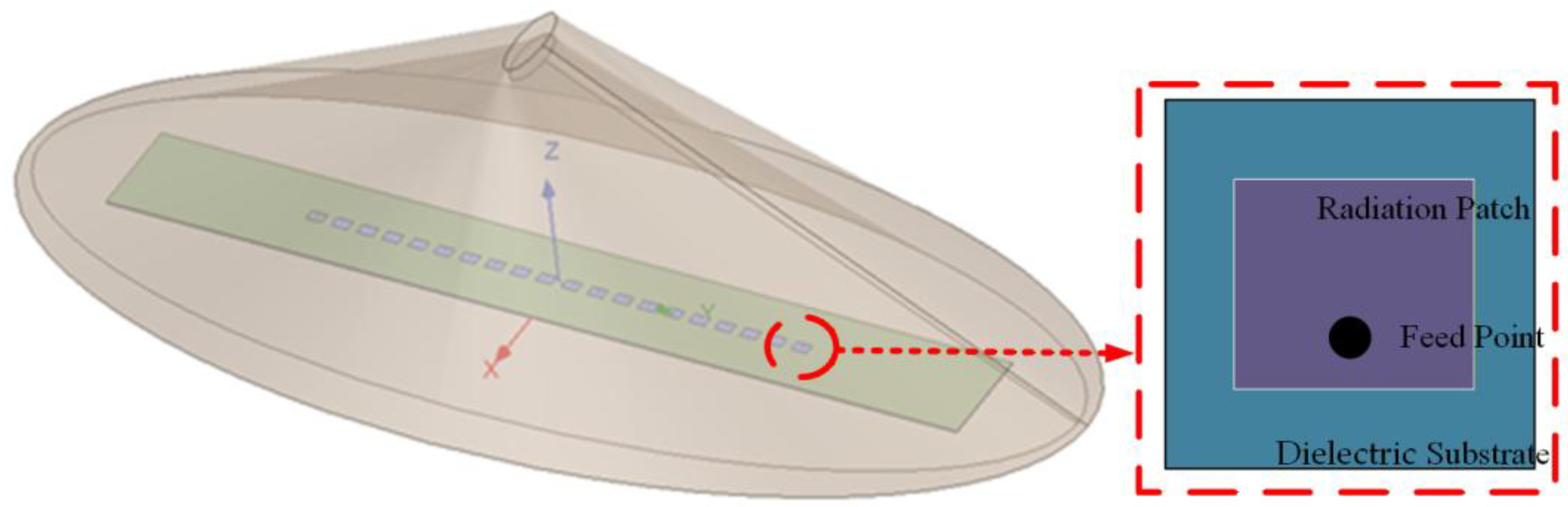
Figure 2.
The optimal DPs and directivities for different ∆θ: (a) The normalized DPs; (b) The directivity variation.
Figure 2.
The optimal DPs and directivities for different ∆θ: (a) The normalized DPs; (b) The directivity variation.
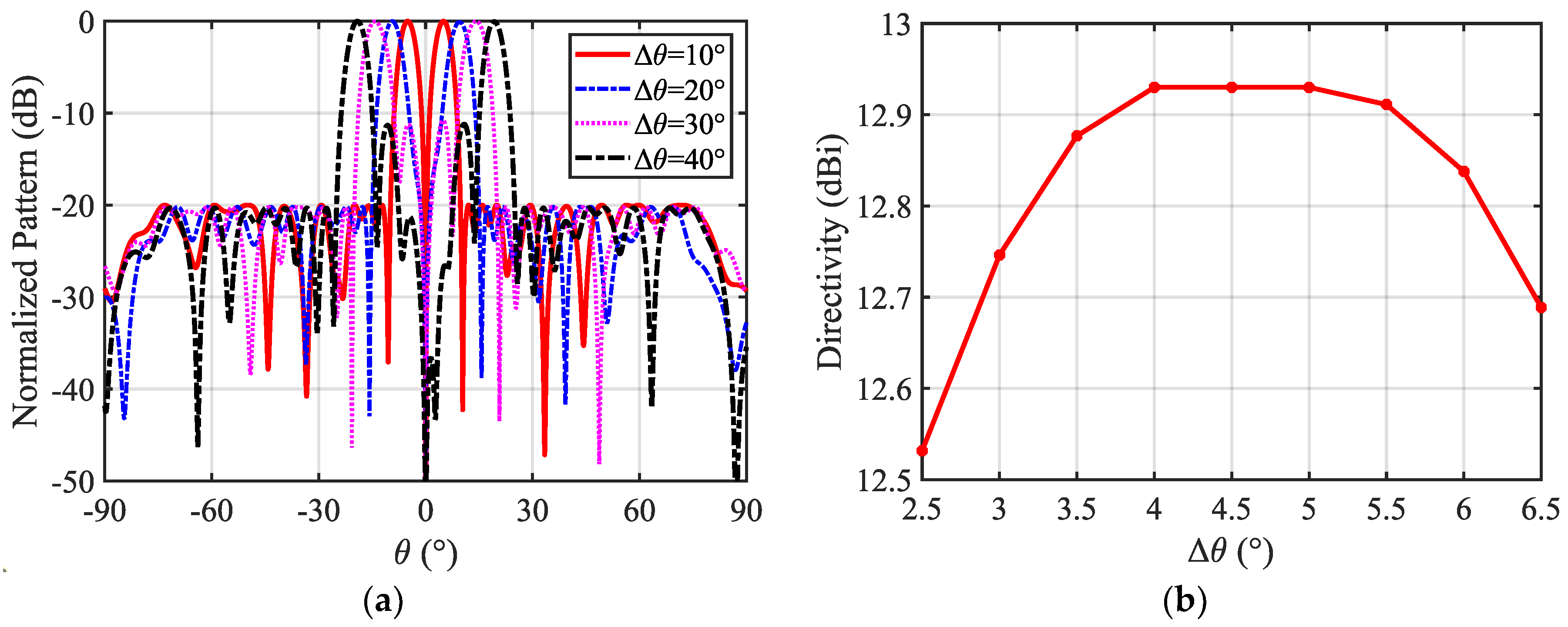
Figure 3.
The normalized DPs with the 0° scan angle obtained by three different methods.
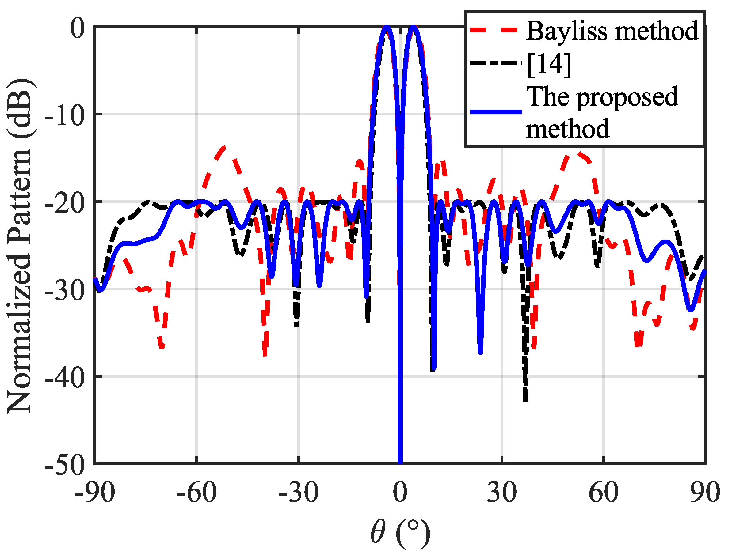
Figure 4.
The normalized DPs with the 30° scan angle obtained by three methods.
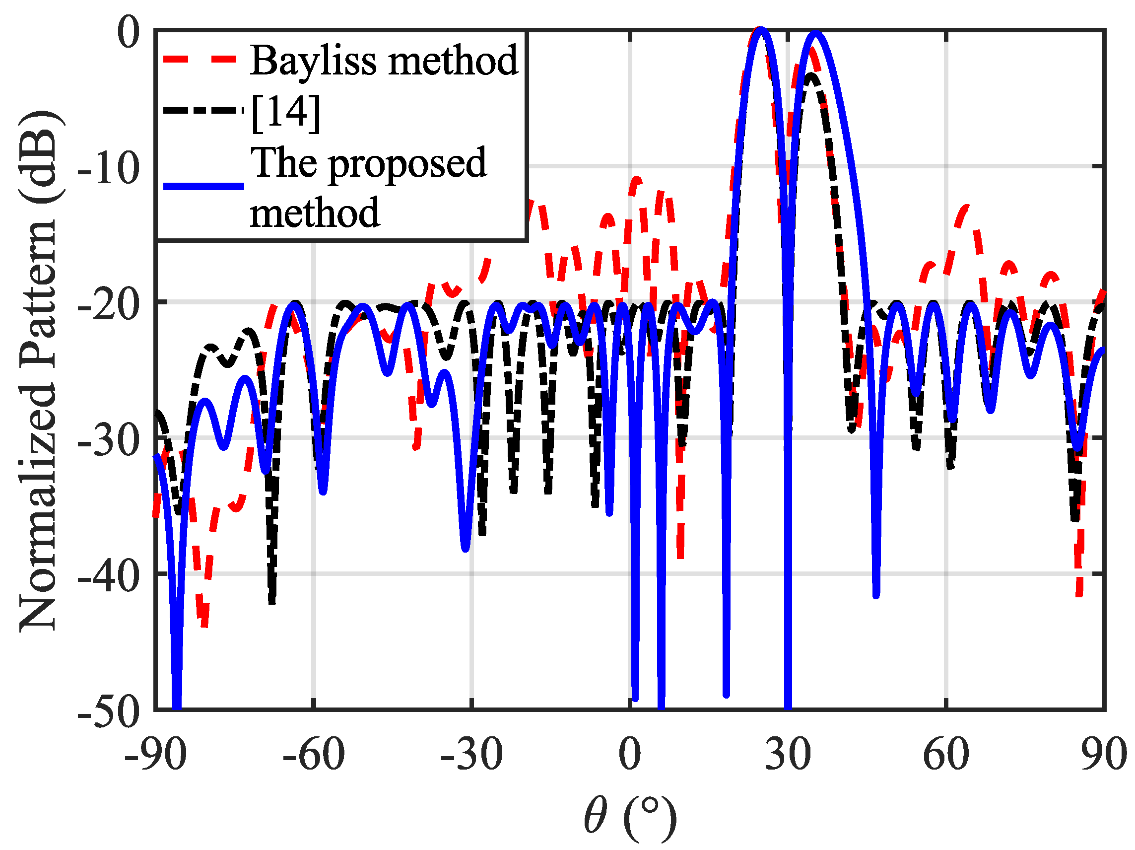
Figure 5.
Structure of the 16×16-element symmetric planar array.
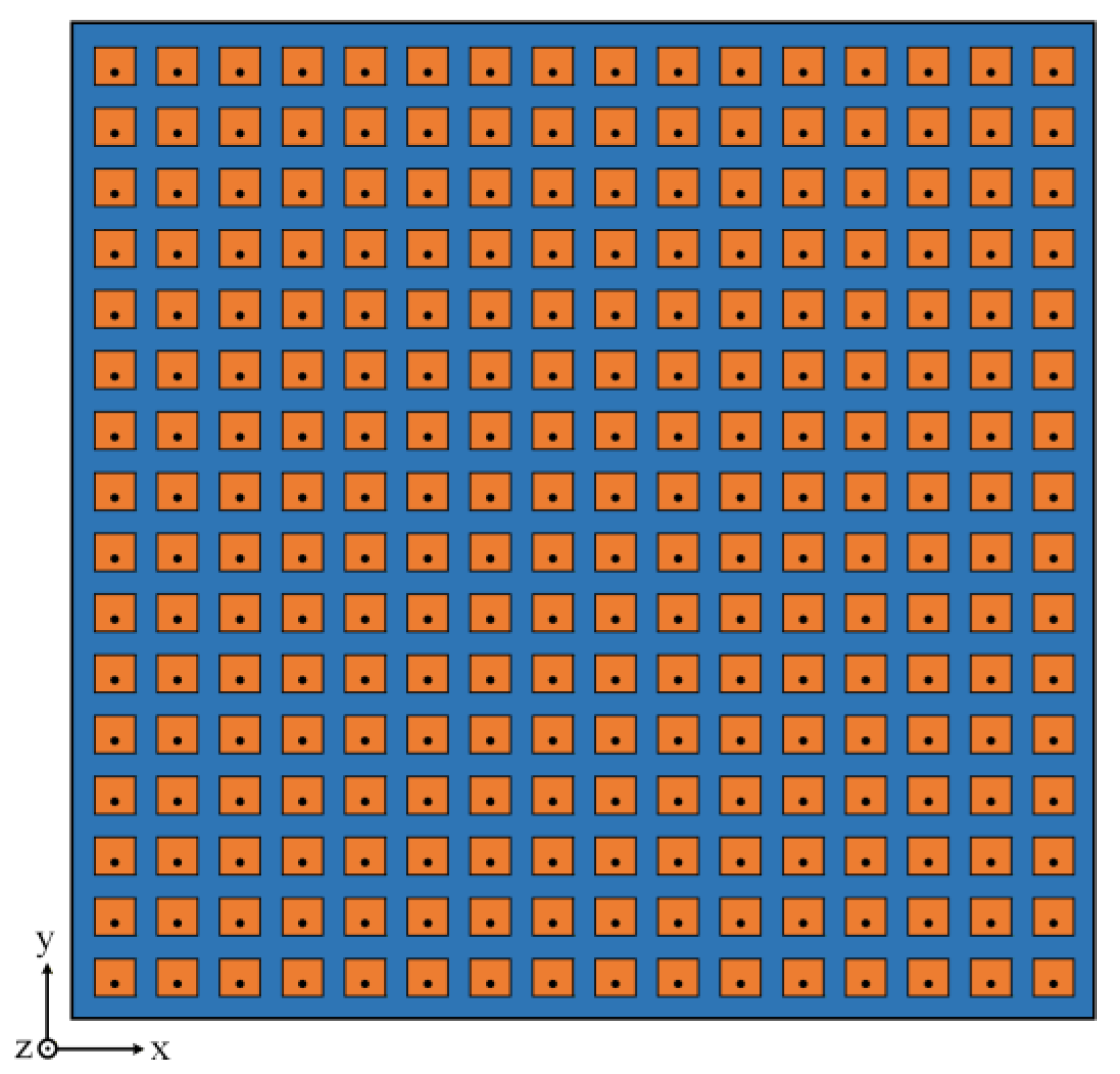
Figure 6.
The optimized radiation patterns of the 16×16-element planar array. (a) The normalized 2D DPs obtained by three different methods; (b) Directivity comparison of the DPs; (c) The normalized 3D DP; (d) Convergence curve of the proposed method.
Figure 6.
The optimized radiation patterns of the 16×16-element planar array. (a) The normalized 2D DPs obtained by three different methods; (b) Directivity comparison of the DPs; (c) The normalized 3D DP; (d) Convergence curve of the proposed method.
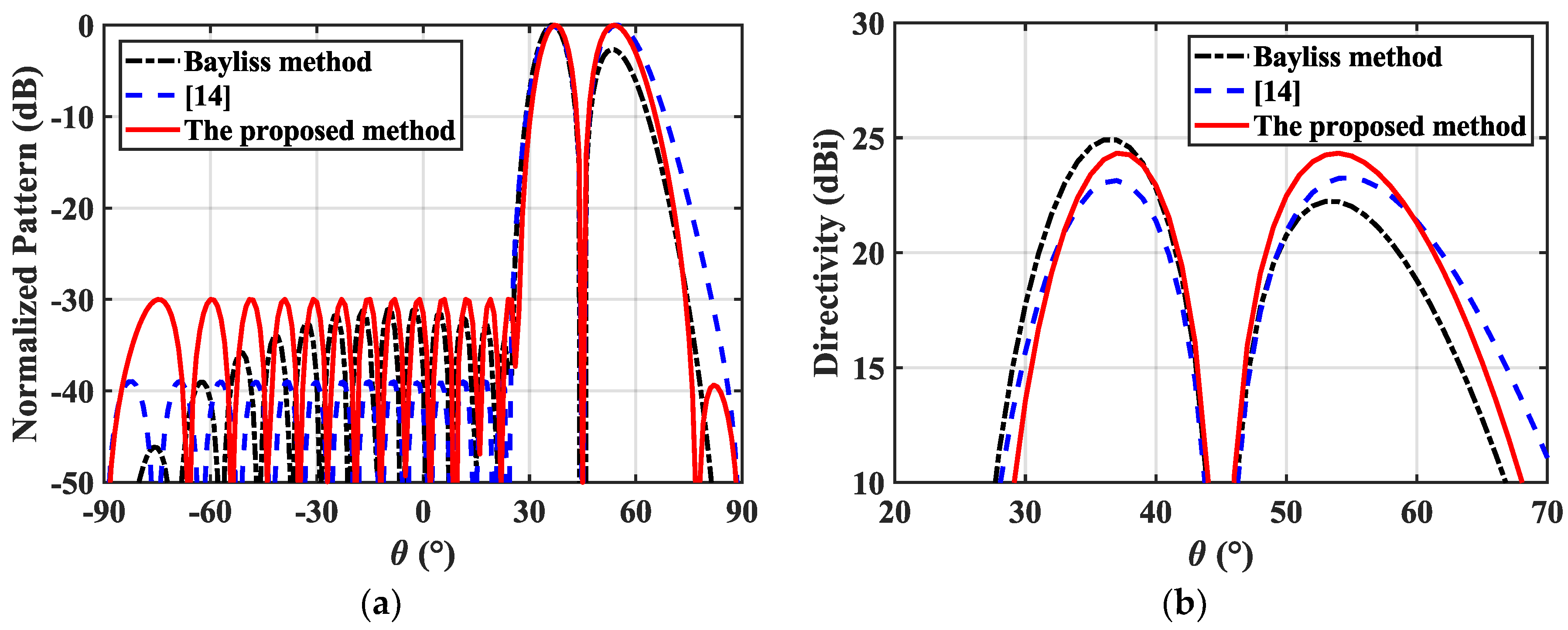
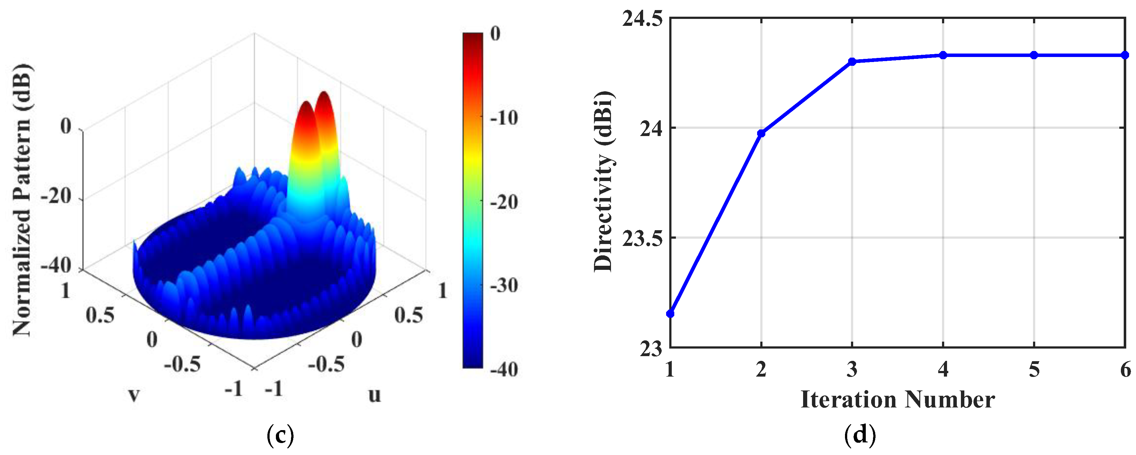

Table 1.
Parameter comparison of the optimal DPs with the 0° scan angle.
| Algorithm | Directivity (dBi) | SLL (dB) | ND (dB) |
| Bayliss method [3] | 12.58 | -13.82 | -37.53 |
| [14] | 12.27 | -20.00 | -50.00 |
| The proposed method | 12.93 | -20.00 | -55.00 |
Disclaimer/Publisher’s Note: The statements, opinions and data contained in all publications are solely those of the individual author(s) and contributor(s) and not of MDPI and/or the editor(s). MDPI and/or the editor(s) disclaim responsibility for any injury to people or property resulting from any ideas, methods, instructions or products referred to in the content. |
© 2026 by the authors. Licensee MDPI, Basel, Switzerland. This article is an open access article distributed under the terms and conditions of the Creative Commons Attribution (CC BY) license (http://creativecommons.org/licenses/by/4.0/).
Copyright: This open access article is published under a Creative Commons CC BY 4.0 license, which permit the free download, distribution, and reuse, provided that the author and preprint are cited in any reuse.


