Submitted:
05 February 2026
Posted:
09 February 2026
You are already at the latest version
Abstract
To solve the problem of constructing the frequency responses (FR) of filters on switched capacitors, which belong to the class of electronic circuits with a periodically changing structure, a method for modeling them in Micro-Cap and Delta Design environments is proposed. It allows you to evaluate the nature of changes in the FR of such filters in the time domain. As an example, a comparative analysis of the frequency response of a second-order analog bandpass filter, as well as two bandpass filter circuits with switching resistors and capacitors, is given. An assessment of the current state of EDA and trends in their development is given.
Keywords:
amplitude-frequency response
; switched capacitor filter
; ARC-filter
; ARCS-filter
; SC-filter
; Micro-Cap
; Delta Design
; Symica
; Kovcheg 3.04
1. Introduction
eCAD or EDA (Electronic Design Automation) is a set of methodologies, algorithms, and software tools that help automate the design, implementation, verification, and testing of electronic systems. The methodology involves a sequential improvement of the design of the device being developed, moving from an abstract, high-level description to a low-level, detailed description of the physical implementation. There are numerous EDA applications available for a wide range of integrated circuit design tasks.
In circuit simulation programs, two modes of circuit analysis are most commonly used - small-signal analysis and transient analysis. So, for example, in the Micro-Cap program, these are the “AC” and “Transient” modes, respectively [1]. Analysis of the circuit in the “AC” mode makes possible to build the amplitude-frequency and phase-frequency responses, and in the Transient mode, we can see the passage of the signal through the circuit under study, as well as the waveforms in its various intermediate nodes. A distinctive feature of the “AC” mode is that it is impossible to build the frequency response of circuits containing nonlinear elements, as well as circuits with switches that are periodically switched on and off under the action of control signals. The latter is due to the fact that when the switches are closed and opened, the configuration of the circuit changes, which determines a new set of equations that describe each state of the circuit. This class includes, for example, filter circuits based on switched capacitors (SC filters) and (or) switched resistors (ARCS filters) [2,3,4,5]. Similar schemes for analyzing their properties should also include synchronous filters, which, in addition to filter blocks, contain analog or switch signal multipliers [6,7].
The main goal and novelty of the article is to review trends in Russian EDA systems, as well as a method for constructing an amplitude-frequency response of filter with a periodically changing structure to evaluate its properties, based on a comparative simulation of ARC, SC, and ARCS filter circuits by analyzing their time-domain circuits in Micro-Cap and Delta Design circuit simulation programs.
2. Key Players in the EDA Field
Functionally, the EDA market is usually divided into five key segments: CAE134, SIP135, (PCB & MCM136), IC Design and Verification, and services. Each of these segments has its own key players. Let's take a closer look at these market segments [8].
CAE (computer-aided engineering) in the context of EDA includes software tools and methods for the design and analysis of electronic systems.
Key companies in this segment include Synopsys (USA), Cadence (USA), Siemens EDA (Germany), Keysight Technologies (USA), and Altium137 (Renesas Electronics, Japan). These companies offer a wide range of solutions for various stages of the design and analysis of electronic systems.
Integrated Circuit Design and Verification is a segment that covers the processes of creating and verifying the functionality, reliability, and performance of integrated circuits (chips).
Key companies in this segment include Synopsys (USA), Cadence (USA), Siemens EDA (Germany), Xilinx (currently part of AMD, USA), Intel PSG (Programmable Solutions Group, USA), and ARM (Softbank, UK/Japan). In recent years, Chinese manufacturers have also emerged and become active in this segment.
Semiconductor Intellectual Property (SIP) blocks are pre-built IP blocks that are used to design integrated circuits and can include processors, memory, interfaces, and other functional modules.
SIPs are particularly important for complex systems on a chip (SoC), which use dozens of IP blocks.
Key players include Arm (UK/Japan), Synopsys and Cadence (USA), Imagination Technologies (UK), and Rambus (USA).
PCB design key players include Cadence (USA), Altium (Renesas Electronics, Japan), Mentor Graphics138 (part of Siemens, Germany), and Zuken (Japan). It is also worth noting the emergence of several growing products in China, including Huawei's domestic products, in Korea (Samsung), and in Japan (Fujitsu).
3. Artificial Intelligence in EDA
As for the distribution of market shares among key players, it is worth noting that the EDA market is effectively monopolized by three companies: Synopsys, Cadence, and Siemens EDA. Together, they account for approximately 75% of the market. However, in recent years, EDA products developed by Chinese companies have been gaining traction. These solutions offer high-quality features at a significantly lower cost.
In recent years, AI has been transforming EDA, making the design process faster, cheaper, and opening up new horizons for innovation. The use of AI technologies in EDA began in the 1990s with early experiments in expert systems, but the active practical application of AI became noticeable in the mid-2010s. In the early stages, in the 1990s and 2000s, AI was used in the form of expert systems that employed pre-coded rules to perform tasks such as logic optimization or routing.
With the advancement of machine learning technologies in the 2010s, the interest in AI in EDA significantly increased. AI began to be actively applied in various stages of the design process. The use of AI has led to reduced development time and improved placement and routing quality.
One important achievement has been the use of AI algorithms that automatically generate design solutions. For example, the DARPA IDEA Intelligent Design of Electronic Assets program has developed methods for automatically generating circuits with little or no engineering input, which is particularly useful for small and medium-sized companies. The IDEA program aims to leverage advancements in applied machine learning, optimization algorithms, and expert systems to provide users without prior design experience with the ability to perform physical design on advanced technology nodes. The goal of the IDEA program is to provide a path for rapid development of next-generation electronic systems without the need for large design teams, reducing the cost and complexity barriers associated with advanced electronic design.
Cadence and Synopsys, the leading EDA companies in the world, have integrated AI into their platforms, significantly reducing iteration times and improving the efficiency of engineering work.
The effects of AI integration in EDA include accelerating the design process, reducing costs, and eliminating the need for manual work, particularly in routine tasks, while also improving the quality of results by finding optimal solutions that are difficult to achieve through traditional methods.
4. Russian EDA Developments
By the early 2020s, the vast majority of electronic CAD systems used in Russia were owned by foreign companies and were designed to meet foreign design and manufacturing standards, such as Synopsys, Cadence, Mentor Graphics, Altium, and Zuken. However, in 2022, as sanctions tightened, many of these CAD software manufacturers stopped supporting Russian users.
It is important to note that the legalization of software is crucial. Typically, foreign chip manufacturing factories verify the legal use of CAD software and SIPs when receiving final chip design files. If this verification is not completed, the customer assumes full responsibility for the quality of the manufactured product.
Unlike in mechanical engineering, where comprehensive domestic software products already exist and are widely used, the situation is different in microelectronics. Currently, a set of disparate tools is being used. Active work is being carried out to create a full-fledged EDA stack, as evidenced by the relevant roadmap of the Ministry of Industry and Trade of the Russian Federation and the activities of industry consortia.
However, the creation of a unified ecosystem that is competitive on a global scale (similar to the solutions offered by Synopsys or Cadence) is a long-term goal. Achieving this goal, which takes years, requires close coordination with the development of domestic chip manufacturing. The key challenge is the lack of mass production in Russia that meets modern technological standards, which makes it difficult to fully debug and validate new EDA tools.
Competing with global brands is challenging. The market is almost monopolized by three companies: Cadence, Siemens, and Synopsys, which hold more than 90% of the market share.
Russia has several specialized institutions that focus on the design of microelectronic systems. However, despite the existing scientific base, there are still no full-fledged commercial domestic EDA systems for electronics. The products available on the market are typically developed by small companies and focus on solving specialized tasks.
There are several similar developments. For example, Integral Solutions LLC develops the Symica EDA system, which is designed for the circuit design of electronic circuits and provides a set of tools for the development of modern analog and digital-to-analog VLSI circuits. Symica EDA supports Process Development Kits (PDK191) from leading integrated circuit manufacturers. The main users of Symica EDA are startups and small and medium-sized design centers.
One of the active developers of domestic EDA systems is Eremex, which creates the Delta Design platform for comprehensive PCB design. In 2024, the company announced a specialized solution for the design and synthesis of integrated circuits, Delta Design Simtera IC, and in 2025, it began commercial sales.
The Technological Center, a research and production company, operates in the market. Its key product, the Kovcheg 3.04 EDA system, is designed for the development of semi-customized CMOS LSI. This system features a unified software shell running on Windows and includes the essential subsystems required for a complete design cycle and product preparation for manufacturing.
In addition to established companies, promising startups are emerging in the field of EDA. A notable example is the SMEKALETS project, which aims to create an intelligent EDA system for microwave integrated circuits. Its innovation lies in the use of artificial intelligence, where evolutionary algorithms and expert systems are employed to automatically select optimal structural and topological designs, as well as component parameters [9].
MemriLab, a specialized EDA system for modeling processes in circuits with nonlinear elements and designing neuromorphic circuitry, is currently under development [10]. This system is designed to simulate memristor elements and design the topology of corresponding integrated circuits.
As evident from this list, Russia has niche solutions for designing individual electronic components, but there are no comprehensive routes (from architecture to transferring the project database for manufacturing) in any of these areas. Additionally, there is no software available for developing complex processor-level chips.
At the Microelectronics 2024 conference, a report by the Industrial Competence Center for Electronics and Microelectronics revealed that Russian developers have 65 "white spots" in the field of software for microelectronics, areas that Russian software cannot yet replace after the departure of foreign companies. Of these, 46 relate to the design of electronic components and six to the design of radio-electronic equipment [11].
In the context of Western sanctions and the pursuit of technological independence, there is a clear demand for the development of domestic electronic component design systems to protect against various types of "backdoors".
In March 2023, a Working Group on the Development of Electronic CAD Systems was established under the Council for the Development of the Electronic Industry, and in 2024, the Ministry of Industry and Trade of the Russian Federation presented a roadmap for the development of Russian electronic and microelectronics CAD systems until 2030, taking into account plans for the localization of production.
The presented roadmap outlines the development of key routes (Digital, Analog, Microwave, Photomasks, Crystal/Substrate/Package, and Devices and Technologies) in the field of microelectronics until 2030.
Let us take a closer look at the EDA Delta Design system from Eremex [12]. The Delta Design system is a versatile tool for developing electronic devices that combines various automated design tools.
The functionality of the Delta Design EDA system provides a full cycle of electronic device development:
- Creation of a database of electronic components and its maintenance.
- Development of electrical schematic diagrams.
- Simulation of analog and digital circuits and analysis of the simulation results.
- Development of printed circuit board designs.
- Placement of components and semi-automatic and automatic routing of printed circuit boards.
- Production of design documentation (in accordance with standards).
- Production of manufacturing documentation, including for automated production lines.
- Preparation of data for compiling a list of purchased products and materials required for the project.
The innovative component model makes creating a database of electronic components in the Delta Design system a simple and intuitive process. Even the most complex component can be added to the database quickly and accurately.
The library manager (LiBerty) provides maintenance of the database of electrical and electronic components in the Delta Design environment. The database of electrical and electronic components is based on a set of libraries. A library is a separate, functionally complete data repository for components, meaning that if a component is included in a library, it means that the library contains all the necessary information for using that component. The use of libraries allows for a clear structure of the database of electrical and electronic components and facilitates the import and export of various groups of components, such as libraries, parts of libraries, individual components, and individual parts of component descriptions.
The structure of working with components includes the following:
- Components are classified into families according to GOST 2.710-91.
- Each family defines a set of technical specifications (attributes).
- A single component can have multiple modifications (radio components).
- The description of a component can correspond to a technical datasheet.
To facilitate the migration of data from third-party EDA systems, Delta Design supports the import of libraries, schematics, and circuit boards from P-CAD 2006, as well as the import of libraries and projects from Altium Designer and PADS.
The functionality of the circuit editor (FlexyS) allows you to design electrical circuits in the Delta Design environment based on the selected design and layout standards, which allows you to combine the design process and documentation production. The system allows you to create circuits with complex hierarchical structures. The extensive toolkit helps the designer to implement even the most complex technical solutions, making their work easier by automating common tasks, such as automatically routing circuits and rearranging the circuit during editing without violating the layout standards, supporting various layout styles, and creating a detailed list of electrical connections (netlist) with the ability to navigate through it. The user-friendly interface of the editor reduces the number of errors during circuit design, preventing the user from performing incorrect actions.
The key features of the system include:
- Automated design using component libraries.
- Compliance with GOST standards for documentation.
- Advanced search for components based on various parameters.
- Automatic diagnostics of component placement accuracy.
- Automatic assignment of position labels.
- Automated routing of electrical connections.
- Built-in library of SPICE components.
- Verification of circuits for completeness and correctness.
- Export to PDF with hypertext navigation.
- Generation of documentation in accordance with industry standards.
The following principles are used to create circuits in FlexyS:
- The circuit is based on individual radio components.
- Each communication line forms a unique circuit.
- Circuits must connect the pins of components.
- Circuits can be combined into buses.
- Circuits are created based on a standard grid.
- Additional graphics do not affect the design process.
Delta Design provides the developer with a set of tools that allow for the simulation of both analog and digital processes in electrical circuits (SimOne and Simtera functionality). The system also allows for the simulation of software that is intended to be used for the device being developed.
SimOne offers a wide range of circuit analysis tools that are similar to those found in classic SPICE programs such as PSpice, Micro-Cap, and OrCad. Additionally, it provides a new feature called circuit stability analysis.
When developing the electronic circuit simulation module, special attention was given to improving the speed and accuracy of calculations compared to its competitors.
SimOne provides the following types of analog circuit analysis:
- DC Analysis.
- AC Analysis.
- Transient Analysis.
- Periodic Steady State Analysis.
- Temperature sweep.
- Parametric sweep.
- Stability Analysis.
- DC sensitivity analysis.
- Sensitivity analysis.
- Monte-Carlo Analysis.
The rules editor (DRM) allows you to manage the rules and technological constraints of the PCB being designed. The rule hierarchy tree is generated based on the complexity of the project. The rules are managed using the principle of inheritance of specified parameters based on the hierarchy of circuits, layers, and regions (areas) on the PCB. Each level of rules is represented by a separate table with consistent data management principles.
The PCB editor (RightPCB) allows you to create PCB designs of any complexity in Delta Design, using a pre-built material library. The placement of components and routing of tracks are performed with continuous monitoring of design rules. Additional control of gaps and conductor lengths is applied for the routing of differential pairs. This approach allows for precise definition of the properties of the designed product and generally improves the efficiency of the development of multi-layered boards. The PCB routing can be performed in an interactive or fully automated mode.
The TopoR autorouter, which is part of Delta Design, significantly reduces the length of parallel traces and reduces the level of cross-electromagnetic interference. The routing of conductors is performed at arbitrary angles, allowing for more efficient use of switching space. The efficiency of autorouting surpasses that of its competitors.
3D visualization not only provides a realistic 3D model of the board, but also allows for tracking the intersections of components, ensuring compatibility between components and their mounting locations, and visualizing the enclosures of electronic devices as specified in standards.
The system enables the generation of design and manufacturing documentation. The format of the manufacturing documentation allows for its use on automated production lines. The design documentation is generated in accordance with the standards chosen by the designer (GOST and ISO standards are available), and the designer has the ability to define their own standards, ensuring compliance with any requirements for design documentation.
Integration API is an extension of Delta Design's functionality that allows users to automate specific design operations. Delta Design includes a set of tools that provide access to the system's core functions through an open-source software interface for working with schematics, printed circuit boards, and electronic component libraries.
Integration API can be used to integrate Delta Design with other systems, and it has already been integrated with the LOMAN:PLM product lifecycle management system.
5. Methodology For Constructing Frequency Response of Filters Based on Comparative Modeling of Analog And Discrete-Analog Filters
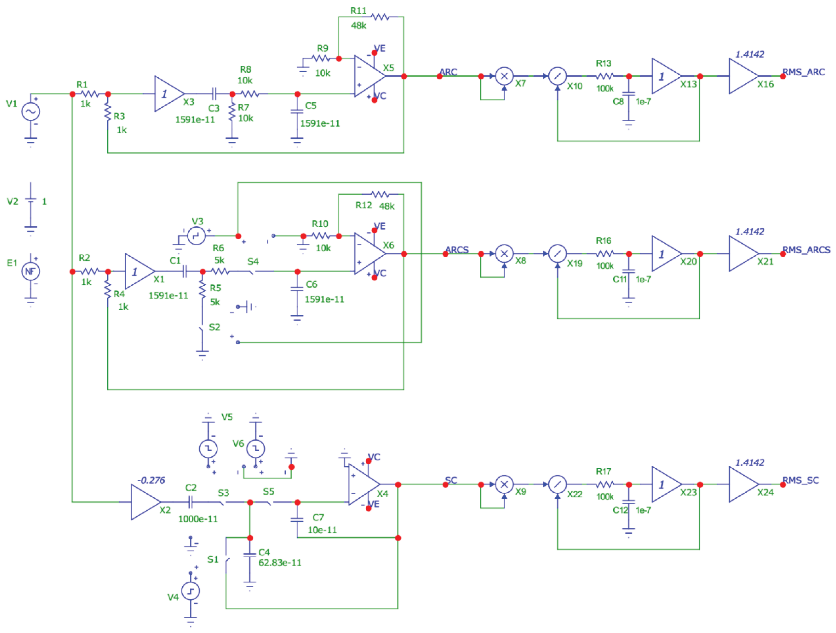
For analysis, we use three modifications of the band-pass filter circuits (Figure 1), which have the same parameters - the frequencies and attenuation of the poles, as well as the transfer ratios at the center frequency. In this circuit the input source of sine-wave voltage V1 is connected simultaneously to the inputs of all three second-order links. In the figure the topmost circuit is an analog active RC filter (ARC filter), the middle circuit is a switched-resistor filter (ARCS filter) and the bottom circuit is a switched-capacitor filter (SC filter) [13,14,15,16,17,18,19,20,21,22,23,24,25,26,27,28]. At the same time, the outputs of these circuits are assigned the symbolic names ARC, ARCS and SC, respectively.
Figure 1.
The generalized scheme for comparative simulation of three filter circuits: from the top to the bottom − ARC filter, ARCS filter and SC filter.
Figure 1.
The generalized scheme for comparative simulation of three filter circuits: from the top to the bottom − ARC filter, ARCS filter and SC filter.
According to the accepted notation in the diagram of Figure 1 the main parameters of the ARC filter are determined by the formulas:
- pole frequency
- attenuation of the pole
- transfer ratio on the pole frequency
Similar for the ARCS filter:
The parameters of the SC filter:
In the above formulas: is a switching period of the controlled switches ARCS and SC filters [17,18,19,20,21,22], and is time of the closed state of switches S2 и S4 during the period of the ARCS filter.
It was noted above that in the “AC” mode, only the analog ARC filter can be analyzed. The frequency response graph of this circuit, obtained by simulation in the AC mode, is shown in Figure 2, and the calculated value of the center passband frequencies of all three filters was chosen to be 1000 Hz. When modeling the circuit, numerical values of the parameters of the elements were used, which were obtained by calculation. This made it possible, when modeling circuits, to exclude additional errors in the resulting characteristics, which could be influenced by the values of the parameters of the elements when choosing their values from existing series, for example E192.
Figure 2.
The frequency response of the analog ARC filter circuit shown in Figure 1.
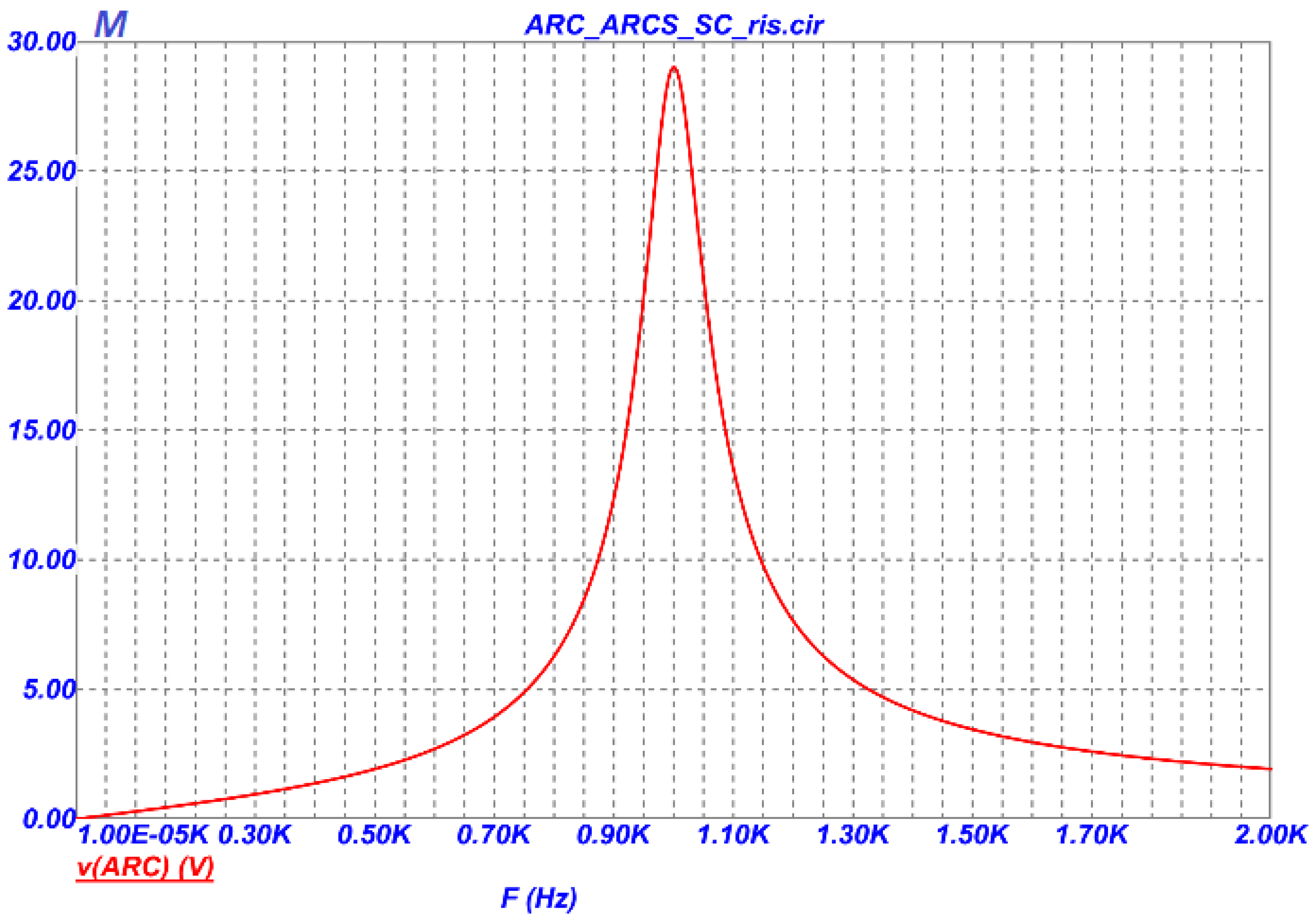
Further, this frequency response graph will be used for comparison with a similar graph obtained by another method.
It is possible to verify the operability of the filter circuits with monitoring switches by obtaining transient responses. To do this, it is necessary to connect constant voltage source V2 with voltage of 1V to the inputs of the circuits and perform the analysis in the “Transient” mode, as is done in Figure 3. The transient characteristics were obtained with the indicated parameters of the passive elements in Figure 3, as well as when setting the source signals that control the pulse switches for ARCS filter (V3) with a sequence of rectangular pulses with a duty cycle equal to , and for the SC filter with sources of rectangular pulses V5, V6 and V4, forming each of them at their outputs alternately once per period pulses equal in duration to one third of the period [4]. During simulation the period of control pulses of all switcs was chosen to be T=100 μs, which corresponds to a switc switching frequency of 10 kHz.
Figure 3.
The transient characteristics of ARC-, ARCS- and SC-filters of Figure 1.
Figure 3.
The transient characteristics of ARC-, ARCS- and SC-filters of Figure 1.
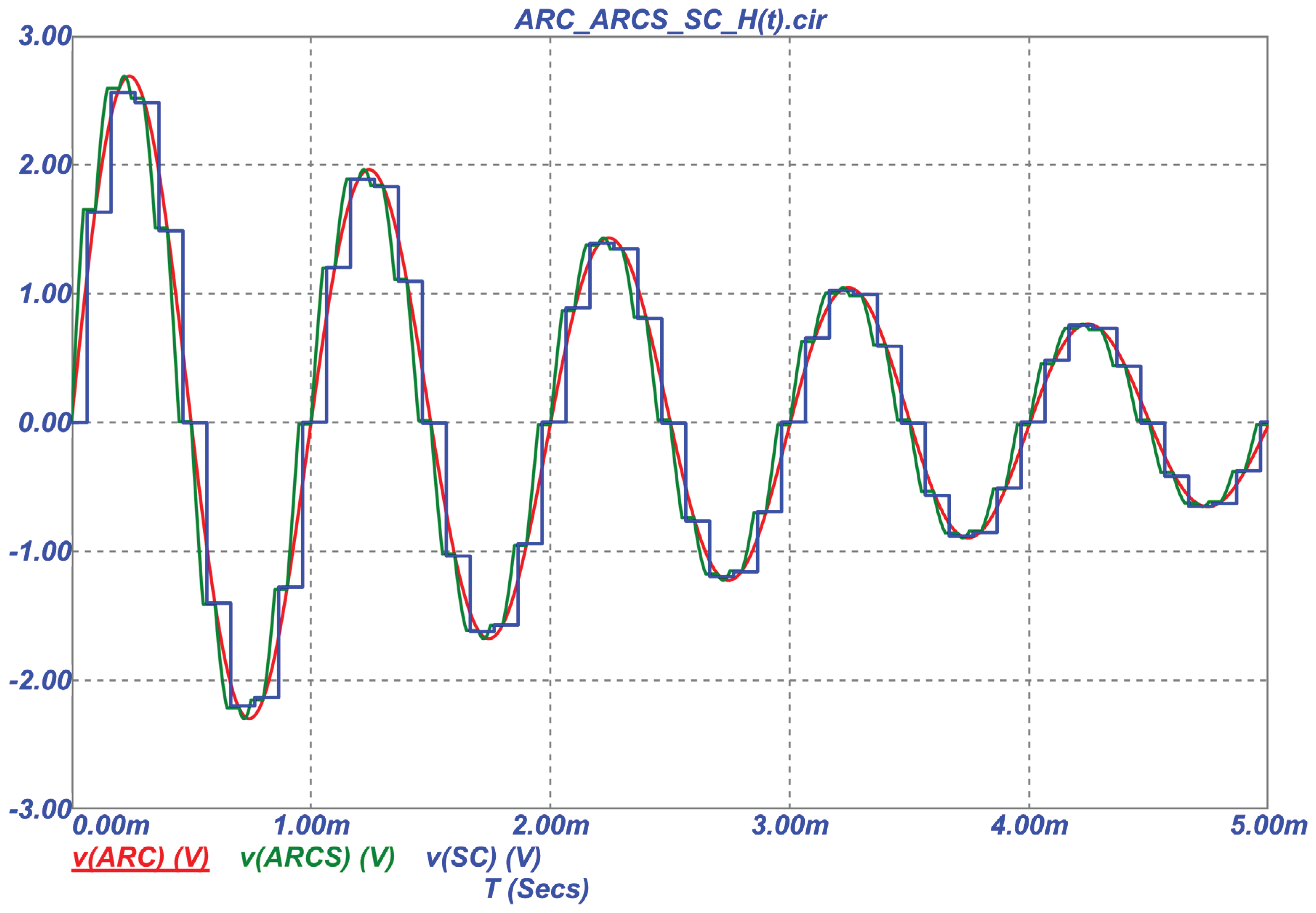
Comparison of the transient graphs of the analog filter circuit (red graph) with the graphs of the ARCS filter (green graph) and the SC filter (blue graph) shows that their nature is very similar, but due to the discrete change in the amplitudes of the output voltages of filters with switches, it is difficult to perform an accurate comparison.
It is known that in practice, to construct the frequency response of the operating device, a sine-wave oscillator connected to its input, and an AC voltmeter is connected to its output. Then, by tuning the oscillator in frequency, the dependence of the output voltage on frequency is removed and frequency response graph is plotted. We use the same idea to construct a simulation circuit and obtain the frequency response of filters with a periodically changing structure.
To construct a tunable sine-wave oscillator, the functional source NF available in the Micro-Сap program (see Figure 1) was used, the output voltage shape of which can be set using a mathematical formula. Instead of the AC voltmeter, the filter outputs are connected to the root-mean-square value (RMS) detectors, made according to the scheme of implicit calculation of the RMS [33], and which convert the AC voltage into the DC voltage proportional to it. To calculate the RMS voltage values [34] in the circuit in Figure 1, blocks of analog multipliers X7-X9 and analog voltage dividers X10, X19, X22 are used, which are available in the Micro-Cap program. The graphs of the filter circuit frequency response at the outputs of the RMS detectors, shown in Figure 4, were obtained by connecting the source NF to the inputs of the filters and setting the output signal of the oscillator using the formula A*sin(π*V*t^2), where A=1V is an amplitude, V is rate of change of frequency (Hz/sec), t is current analysis time.
Figure 4.
The frequency response graphs of three filters obtained in the “Transient” mode.
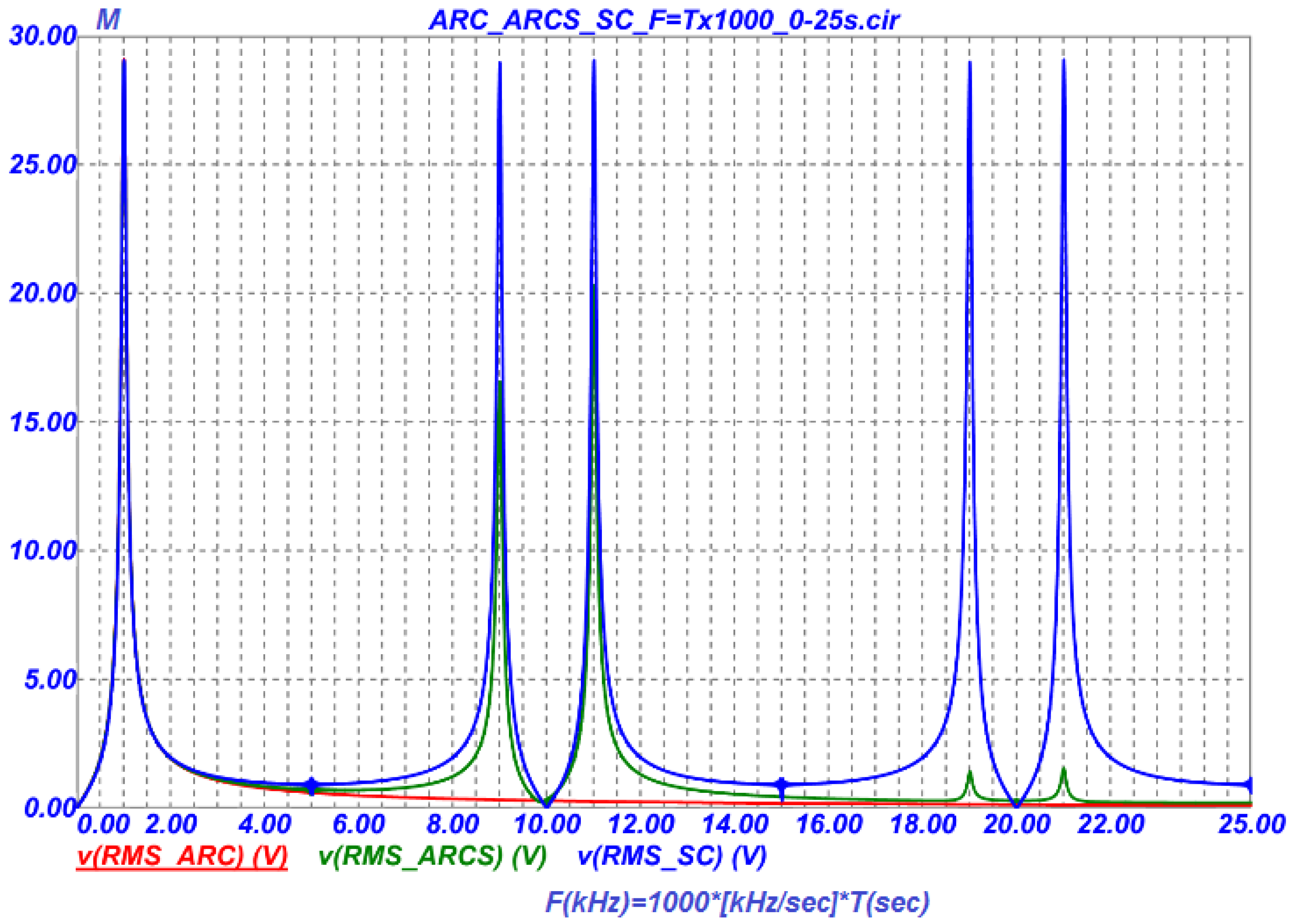
The frequency response graphs shown in Figure 4 were obtained at V=1000 Hz/sec. Since the graphs were obtained in the “Transient” mode, the time T(Secs) is displayed along the abscissa, but taking into account the selected rate of oscillator tuning on frequency F(kHz), 1 sec corresponds to 1 kHz on the graphs. Thus, the given frequency response graphs correspond to the bandwidth of the filter link circuits from 0 to 25 kHz.
From the analysis of the obtained graphs, it follows that in the operating bandwidth up to the half the sampling frequency, i.e. up to 5 kHz, the graphs are practically indistinguishable, and after this frequency they have significant differences, which are in good agreement with the theory presented, for example, in [2].
The reproduction accuracy of the frequency response obtained in the graphs of Figure 4 depends on the realizable attenuations (quality factors) of the filter circuits, on the time constants of the low-pass filters, on the basis of which the circuits of the RMS detectors are made, and also on the rate of frequency tuning of the sine-wave oscillator. The listed parameters lead to a shift in the frequency of the maximum of the frequency response to the right, and with a quick tuning of the oscillator, they can also cause a decrease in the transfer ratio.
Figure 5 shows the frequency response graphs of the filters in the bandwidth on the enlarged scale at the oscillator tuning rate of 1000 Hz/s, and Figure 6 illustrates similar graphs at the tuning rate of 100 Hz/sec. From the comparison of the graphs, it is clearly seen that the lower the oscillator tuning rate, the less transients affect in the circuits and the more accurately the frequency response graphs are displayed.
Figure 5.
The frequency response of the filters within the operating bandwidth at the tuning rate of the oscillator frequency of 1000 Hz/sec.
Figure 5.
The frequency response of the filters within the operating bandwidth at the tuning rate of the oscillator frequency of 1000 Hz/sec.
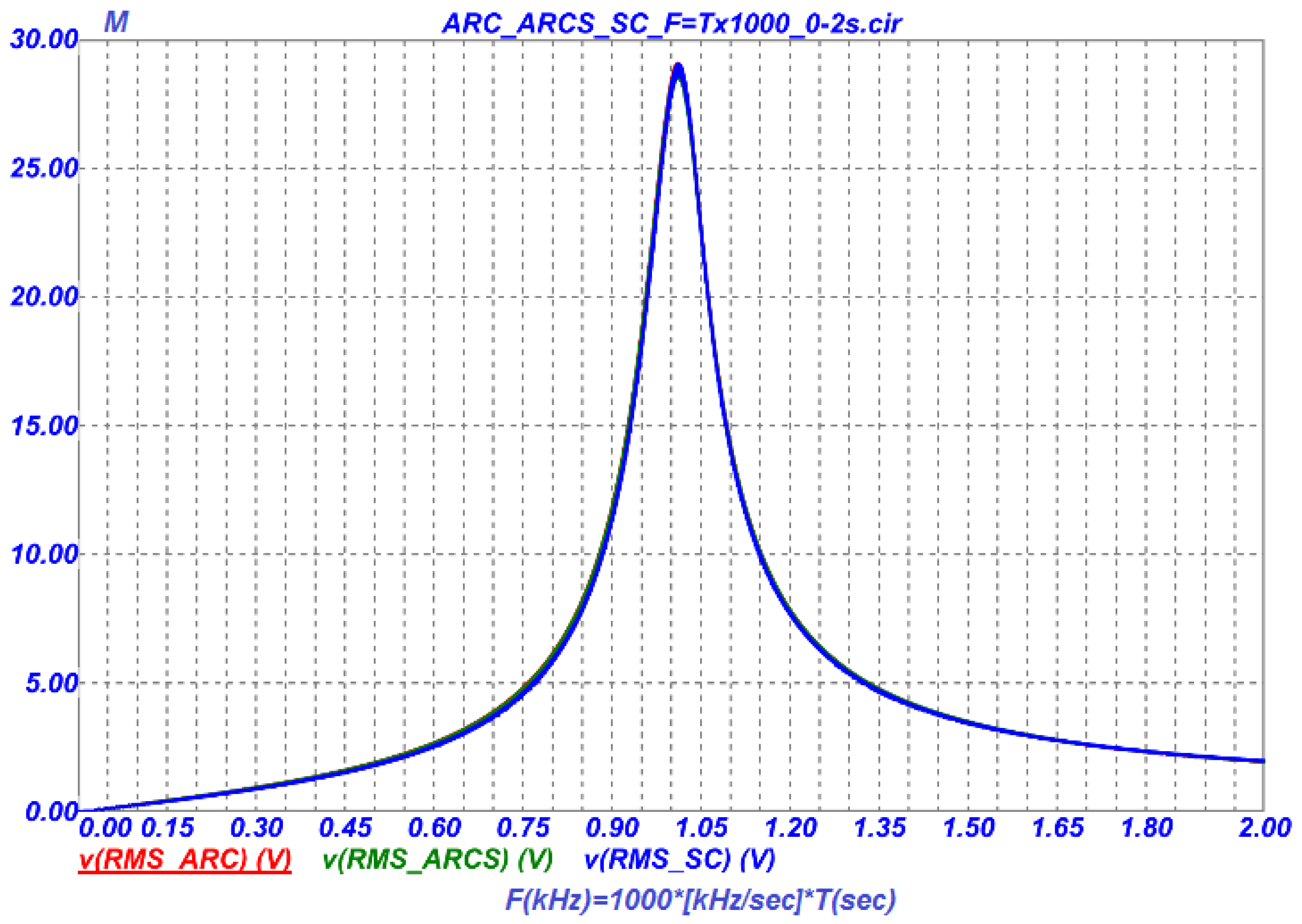
Figure 6.
The frequency response of filters within the operating bandwidth at the tuning rate of the oscillator frequency of 100 Hz/sec.
Figure 6.
The frequency response of filters within the operating bandwidth at the tuning rate of the oscillator frequency of 100 Hz/sec.
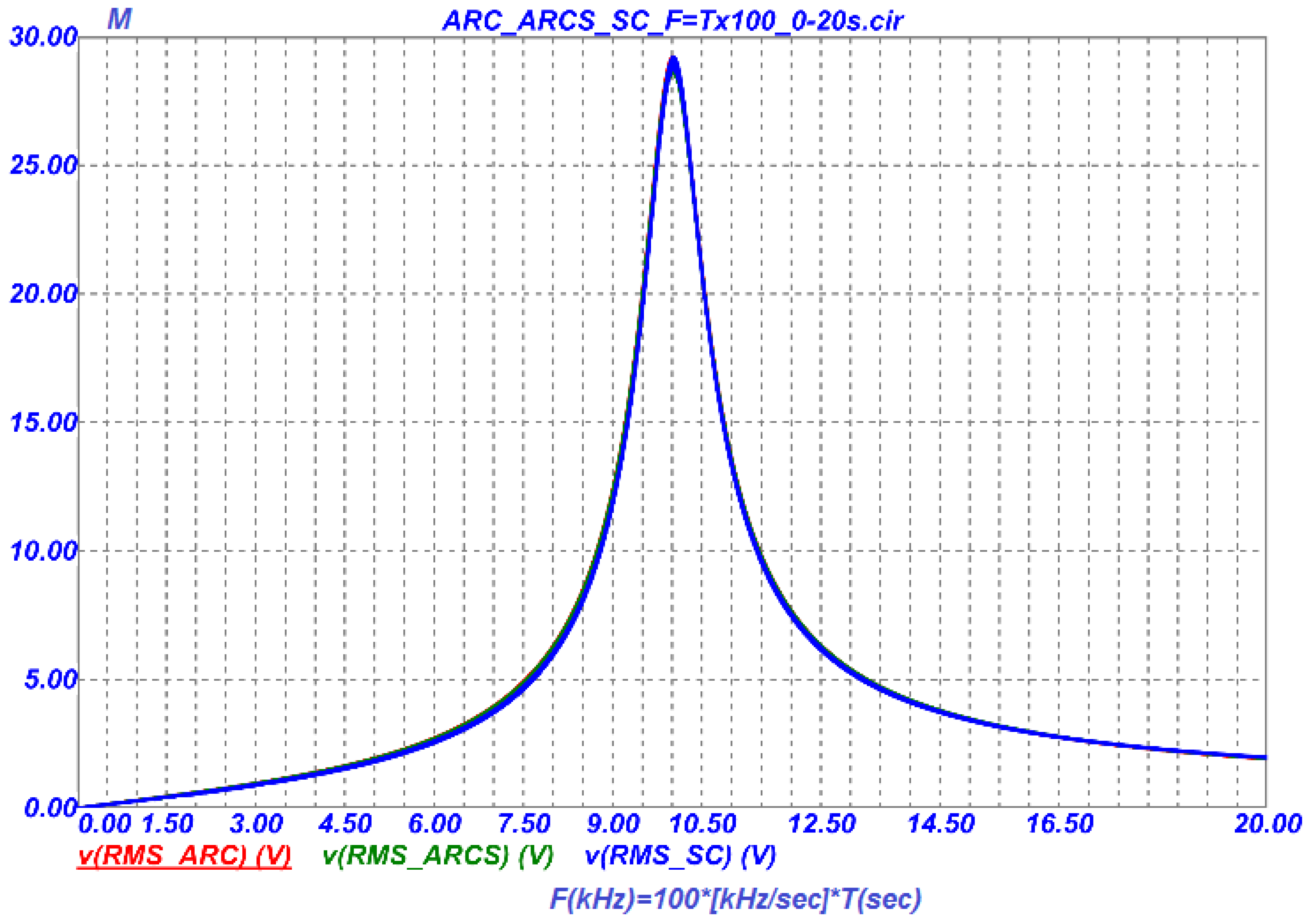
Comparison of the frequency response graph of the analog filter (Figure 2), obtained in the “AC” mode, and the frequency response graphs of the SC, ARCS filters with a periodically changing structure (Figure 6), obtained in the “Transient” Micro-Cap mode, shows that the techniques suggested in this work, can be used to study the properties of the switched-capacitor filters.
The second-order link of the SC filter, shown in Figure 1 has an interesting feature. Its pole frequency, i.e. the center frequency of the passband can be tuned by changing the capacitance of only one capacitor, while the transfer ratio and attenuation in the link remain unchanged [4].
Figure 7.
Tuning of the pole frequency of the SC filter in the operating bandwidth with a discrete change in the capacitance of capacitor C4.
Figure 7.
Tuning of the pole frequency of the SC filter in the operating bandwidth with a discrete change in the capacitance of capacitor C4.
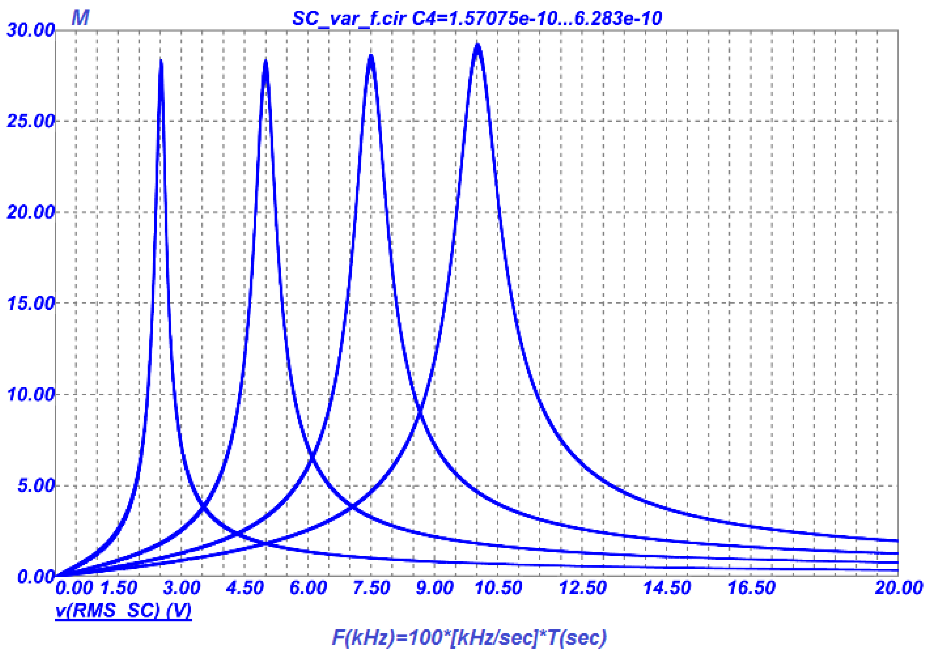
To demonstrate how the techniques proposed in this paper work, Figure 7 shows the obtained frequency response graphs of the SC filter with a discrete change in the capacitance of capacitor C4 within the range from 157.075 pF to 628.3 pF with a step of 157.075 pF, which corresponds to the tuning of the center frequency from 250 Hz to 1000 Hz with a step of 250 Hz.
6. Features of Comparative Filter Modeling in the Delta Design Environment
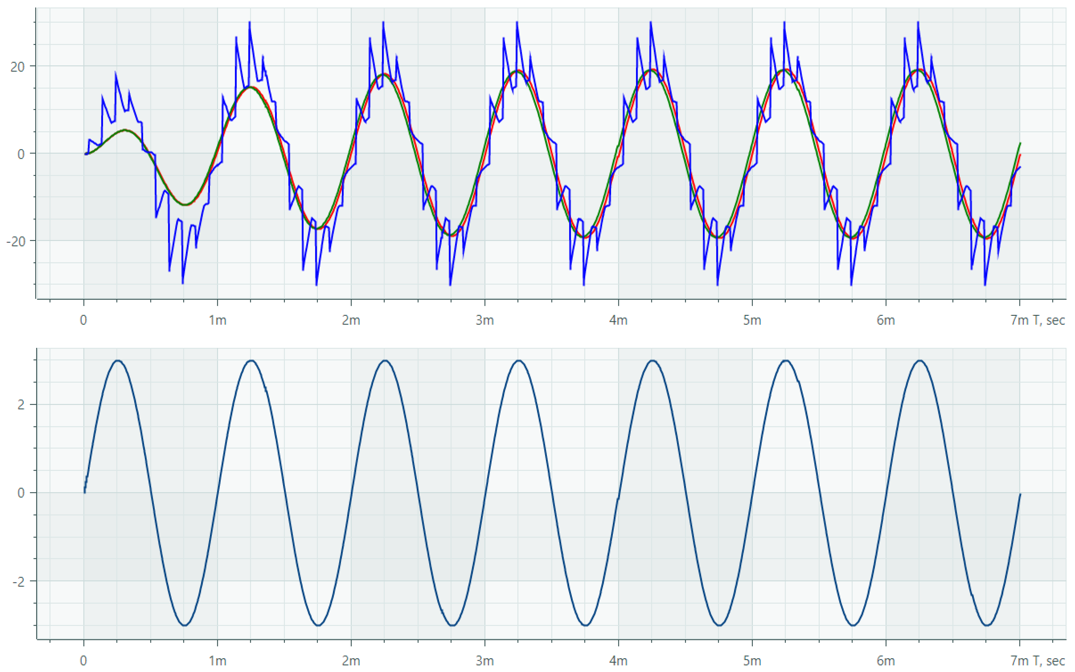
SimOne is a full–featured analog modeling module within Delta Design EDA. It implements SPICE-compatible modeling and is designed to analyze the behavior of electronic circuits at the level of analog components. The simulation of the circuit in Figure 1 in the “Transient” mode is shown in Figure 8. A sinusoidal signal with a frequency of 1kHz and an amplitude of 3V is applied to the input of all filters. According to the transmission coefficient equations, there is an amplification of the output signal at the center frequency. The upper graph shows the output of the ARC filter in red, the ARCS filter in green, and the SC filter in blue. The lower graph corresponds to the input signal.
Figure 8.
Transient analysis in Delta Design EDA.
The RMS measurement circuit could not be assembled in Delta Design, since the necessary primitives of analog signal multipliers and dividers are missing here. However, the standard library contains the LTC1966 RMS-to-DC converter model from Analog Devices, which could be used as a replacement. Nevertheless, there were problems with the simulation, since EDA consumes too much RAM to calculate transients lasting more than 1 s (it took at least 25 s for experiments). Therefore, it was not possible to repeat the method of measuring the frequency response of discrete-analog filters (DAF) in Delta Design on an experimental device. It is possible that there will be a memory leak in the software.
7. Conclusions
An assessment of the current state of Russian EDA systems is given, and the trends of their development are considered. Russian developers are following the path of import substitution of Western analogues, especially in the field of microelectronics (Symica and Kovcheg 3.04) and the full development cycle of printed circuit board devices (Delta Design).
A technique for constructing the amplitude-frequency characteristics of filters with switchable capacitors by modeling their circuits in a Micro-Cap environment in the "Transient" mode has been developed and tested in practice. It allows us to evaluate the nature of changes in the frequency response of such filters in the time domain [37]. The results obtained are recommended for use in the analysis of electronic circuits with periodically changing structure, including SC and ARCS filters.
The features of comparative modeling of the amplitude-frequency characteristics of DAF in the Delta Design environment are considered. One of the significant limitations in this case is the smaller number of modeling primitives in the standard library compared to Micro-Cap. There were also some problems with the performance of the EDA itself.
Funding
The research has been carried out at the expense of the Grant of the Russian Science Foundation (project No. 23-79-10023), https://rscf.ru/en/project/23-79-10023/.
Conflicts of Interest
The authors declare no conflict of interest.
References
- Micro-Cap 12. Information. Available online: https://gotroot.ca/spectrum/www.spectrum-soft.com/download/download.html (accessed on 4th February 2026).
- Allen, Ph. E.; Sanchez-Sinencio, E. Switched Capacitor Circuits; Springer Dordrecht, 1984. [Google Scholar]
- Ivanov, Yu.I. “Second Order Multiplex SC Filters” Interacademic subject scientific collection “Selecting Closed Loop Systems”; (in Russian). TRTI: Taganrog, 1991; pp. 126–130. [Google Scholar]
- Tepin, V.P. Patent No. 1510072 USSR; Bandpass SC-Filter: publ. 23.09.92. (in Russian). Bull. No. 35 / Ivanov Yu.I.
- Tepin, V.P. Patent No. 1732434 USSR; Tunable ARCS-Filter: publ. 07.10.90. (in Russian). Bull. No. 37 / Ivanov Yu.I.
- Tepin, V.P. Patent No. 1598120 USSR; Bull. No. 17 / Ivanov Yu.I. (in Russian). Synchronous Filter.
- Khristich, V.V. “Complex Synchronous Filters”. News of TRTI, Selecting Closed Loop Systems, 1995; pp. 78–82. [Google Scholar]
- Abakumov, E.M.; Lysachev, M.N.; Prokhorov, A.N. Microelectronics. Analysis, trends, global experience; 480 p. (in Russian). Boiko, A., Pravosudov, P., Eds.; Sci. IP Betretdinov R.G.: Moscow, Russia, 2026. [Google Scholar]
- The 50om team of the TUSUR business incubator has received the status of a Skolkovo resident. Available online: https://sbi.tusur.ru/50om_resident (accessed on 4th February 2026).
- MemriLAB Electronic Design Automation System for Neuromorphic Systems. Available online: https://memrilab.polyketon.ru/en/ (accessed on 4th February 2026).
- After the flight of foreigners, 65 "white spots" remained in the Russian microelectronics software. Available online: https://www.cnews.ru/news/top/2024-10-17_posle_uhoda_inostrantsev (accessed on 4th February 2026).
- Delta Design. Available online: https://www.eremex.ru/products/delta-design/ (accessed on 4th February 2026).
- Ismail, Mohammed; Franca, José. Introduction to Analog VLSI Design Automation. In The Springer International Series in Engineering and Computer Science (SECS; 1990; volume 95, p. 192 p. [Google Scholar]
- Carusone, Tony Chan; Johns, David A.; Martin, Kenneth W. Analog integrated circuit design, 2nd ed.; John Wiley & Sons, Inc., 2011; p. 822 p. [Google Scholar]
- Razavi, Behzad. Design of analog CMOS integrated circuits, Second edition; professor of electrical engineering, University of California: Los Angeles; McGraw-Hill Education, 2017; p. 801 p. [Google Scholar]
- Allen, Phillip E. “CMOS Analog Circuit Design”, Third Edition; Oxford University Press, 2012; p. 783 p. [Google Scholar]
- Sedra, Adel S.; Smith, Kenneth C. “Microelectronic Circuits”, Seventh Edition; Oxford University Press, 2014; p. 1488 p. [Google Scholar]
- de Andrade Serra, Hugo Alexandre; Paulino, Nuno. “Design of Switched-Capacitor Filter Circuits using Low Gain Amplifiers”. In SpringerBriefs in Electrical and Computer Engineering; 2015; p. 92 p. [Google Scholar]
- Tumati, S. “Design of large time constant switched-capacitor filters for biomedical applications”; 2005; p. 138 p. [Google Scholar]
- Sanchez-Sinencio, E.; Silva-Martinez, J.; Geiger, R. Biquadratic SC filters with small GB effects. IEEE Transactions on Circuits and Systems 1984, vol. 31(no. 10), 876–884. [Google Scholar] [CrossRef]
- Duque-Carrillo, J. F.; Silva-Martinez, J.; Sanchez-Sinencio, E. Programmable switched-capacitor bump equalizer architecture. IEEE Journal of Solid-State Circuits 1990, vol. 25(no. 4), 1035–1039. [Google Scholar] [CrossRef]
- Xuexiang, C; Sánchez-Sinencio, E; Geiger, RL. “Pole-zero pairing strategies for cascaded switched-capacitor filters”. Proceedings IEE 1987, 134(4), 199–204. [Google Scholar] [CrossRef]
- Ausin, J. L.; Duque-Carillo, J. F.; Torelli, G.; Sanchez-Sinencio, E.; Maloberti, F. Periodical nonuniform individually sampled switched-capacitor circuits. 2000 IEEE International Symposium on Circuits and Systems (ISCAS) 2000, vol.5, 449–452. [Google Scholar] [CrossRef]
- Sánchez-Sinencio, E; Gómez-Osorio, JL. “Switched-capacitor simulation of grounded inductors using operational-amplifier pole”. Electronics Letters 1979, Vol. 15(Issue 6), 160–170. [Google Scholar] [CrossRef]
- Alagappan, A.; Soto-Aguilar, S.; Sánchez-Sinencio, E. Reduced clock harmonic distortion technique in maximum tunable switched-R-MOSFET-C filters. 2014 IEEE 57th International Midwest Symposium on Circuits and Systems (MWSCAS), 2014; pp. 1037–1040. [Google Scholar] [CrossRef]
- Ausín, J.L.; Torelli, G.; Duque-Carrillo, J.F.; et al. Series/Parallel Time-Multiplexed Switched-Capacitor Filters with Programmability Based on Non-Uniform Sampling. Analog Integr Circ Sig Process 2006, 46, 241–252. [Google Scholar] [CrossRef]
- Garcia-Vazquez, J.; Sanchez-Sinencio, E. Finite gain - bandwidth product effects on a pair of pseudo-N-path SC filters. IEEE Transactions on Circuits and Systems 1984, vol. 31(no. 6), 583–584. [Google Scholar] [CrossRef]
- Sánchez-Sinencio, E; Ramirez-Angulo, J; Geiger, RL. “Computer-aided program for reduction of total capacitance in cascade sc filters”. 29th Midwest Symposium on Circuits and Systems, 1987; pp. 597–599. [Google Scholar]
- Serra, H.; Oliveira, J. P.; Paulino, N. A 0.9-V Programmable Second-Order Bandpass Switched-Capacitor Filter for IoT Applications. IEEE Transactions on Circuits and Systems II: Express Briefs 2018, vol. 65(no. 10), 1335–1339. [Google Scholar] [CrossRef]
- Parisi, A.; Papotto, G.; Ragonese, E.; Palmisano, G. A 1-V 7th-Order SC Low-Pass Filter for 77-GHz Automotive Radar in 28-nm FD-SOI CMOS. Electronics 2021, 10, 1466. [Google Scholar] [CrossRef]
- Wakaumi, Hiroo. “A Switched-Capacitor Low-Pass Filter with Dynamic Switching Bias OP Amplifiers”. Advances in Science, Technology and Engineering Systems Journal 2017, Vol. 2(No. 6), 100–106. [Google Scholar] [CrossRef]
- Retdian, N.; Shima, T. Design of low-noise switched-capacitor low-pass filters with adaptive configuration. 2015 European Conference on Circuit Theory and Design (ECCTD), 2015; pp. 1–4. [Google Scholar] [CrossRef]
- A Basic Introduction to Filters—Active, Passive, and Switched-Capacitor; Application Note 779; National Semiconductor: Kerry Lacanette, 21 April 2010.
- Timonteev, B.N.; Velichko, L.M.; Tkachenko, V.A. Analog signal multipliers in radioelectronic equipment; 112 p. (in Russian). Radio and communication: Moscow, Russia, 1982. [Google Scholar]
- Denisenko, D.; Titov, A.; Butyrlagin, N.; Zhuk, A. Research of a Filter on Switchable Capacitors with Three-Phase Control of Electronic Keys. In 2024 Wave Electronics and its Application in Information and Telecommunication Systems (WECONF); St. Petersburg, Russian Federation; Volume 2024, pp. 1–4. [CrossRef]
- Denisenko, D.; Titov, A.; Prokopenko, N.; Butyrlagin, N. Discrete-Analog Filters on Switchable Capacitors with a Summator of Input and Output Signals on a Differential Difference Operational Amplifier. 2024 IEEE Ural-Siberian Conference on Biomedical Engineering, Radioelectronics and Information Technology (USBEREIT), Yekaterinburg, Russian Federation, 2024; pp. 106–109. [Google Scholar] [CrossRef]
- Denisenko, D.; Ivanov, Y.; Prokopenko, N.; Titov, A. Techniques for Constructing Amplitude Frequency Characteristics of Switched-Capacitor Filters by Comparative Simulating their Circuits in Micro-Cap Environment. 2023 International Conference on Electrical Engineering and Photonics (EExPolytech), ST PETERSBURG, Russian Federation, 2023; pp. 18–21. [Google Scholar] [CrossRef]
Disclaimer/Publisher’s Note: The statements, opinions and data contained in all publications are solely those of the individual author(s) and contributor(s) and not of MDPI and/or the editor(s). MDPI and/or the editor(s) disclaim responsibility for any injury to people or property resulting from any ideas, methods, instructions or products referred to in the content. |
© 2026 by the authors. Licensee MDPI, Basel, Switzerland. This article is an open access article distributed under the terms and conditions of the Creative Commons Attribution (CC BY) license (http://creativecommons.org/licenses/by/4.0/).
Copyright: This open access article is published under a Creative Commons CC BY 4.0 license, which permit the free download, distribution, and reuse, provided that the author and preprint are cited in any reuse.


