
Submitted:
15 November 2023
Posted:
15 November 2023
You are already at the latest version
Abstract
We offered the circuit of a discrete analog filter (DAF) low frequencies of second-order on switchable capacitors, which differs from the known ones in that three capacitors with one terminal are connected to a common bus, and the frequency of the DAF pole depends not only on the ratio of the capacitances of the frequency-setting capacitors, but also on the ratio of resistances two additional resistors in the feedback. This allows at constant values of the capacitances and a fixed switching frequency of electronic switches, control the pole frequency by changing the resistance ratio of additional resistors. Computer simulation of the developed circuit was performed in the Micro-Cap environment. It has been established that the DAF has a transmission coefficient close to minus one at very low frequencies and a transmission coefficient close to zero at higher frequencies.
Keywords:
discrete-analog low-pass filter
; switched capacitors
; transient process
; second-order transfer function
; operational amplifier
; electronic switch
; micro-Cap
1. Introduction
Despite the fact that the digital transformation of industrial production makes extensive use of digital analog signal processing methods, they are redundant in some cases. As a consequence, discrete-analog processing, which combines the main advantages of analog-digital methods, is very promising. Thus, discrete-analog filters on switched capacitors (DAF), produced by dozens of leading microelectronic companies in the world, incl. Texas Instruments (USA), Maxim (USA), CYPRESS (USA), Analog Devices (USA), etc., provide a significant gain (in comparison with classic digital and analog filters) in size, cost, accuracy, functionality and are an effective means construction of frequency selection circuits and processing of analog signals in science and technology.
Discrete-analog switched capacitor filters and their practical applications have become the subject of intense intellectual property protection in almost every country in the world over the past 30 years [1,2,3,4,5,6]. The most promising DAF solutions [1,2,3,4,5,6] are patented by companies in the USA, Japan, France, Taiwan, China, Germany, Great Britain, Italy, etc.
The main goal and novelty of the article is to create and study a discrete-analog low-pass filter (LPF) based on switched capacitors [7], with adjustment of the pole frequency by changing the resistance ratio of additional resistors at a fixed switching frequency of electronic switches.
2. Discrete-Analog Low-Pass Filter with Resistive Pole Frequency Adjustment
Figure 1 shows the developed DAF [7], where three frequency-setting capacitors C1, C2 and C3 are connected to a common bus, which increases the manufacturability of the DAF in microelectronic design. On Figure 1 designated is BA - buffer amplifier, OA – operational amplifier, Us4, Us5 – voltage applied to electronic keys.
With sequential and periodic closure of the first S1 and third S3, as well as the second S2 and fourth S4 electronic keys, in conditions where the frequency switching frequency of electronic keys much higher than the pole frequency of the second-order link, as a result of mathematical analysis of the DAF circuit in Figure 1 it can be shown that this circuit implements the transfer function of a second-order low-pass filter (LPF) in the low-frequency region.
the main parameters of which are found using the following formulas:
- -
- LPF transmission coefficient at zero frequency
- -
- LPF transmission coefficient at the pole frequency
- -
- pole frequency
- -
- pole attenuation
In formula (4), is the switching frequency of electronic keys, and is their switching period, R1 and R2 are the resistances of the first R1 and second R2 additional resistors, C1, C2, C3 and C4 are the capacitances of the first C1, the second C2, third C3 and fourth C4 frequency-setting capacitors, respectively.
Thus, the frequency of the low-pass filter pole (formula (4)) depends both on the ratio of the capacitances of the frequency-setting capacitors and on the ratio of the resistances of additional resistors R1 and R2. Consequently, with constant C1, C2, C3, C4 and , the frequency of the low-pass filter pole can be changed by the ratio of resistances R2 to R1.
As control signals, the first S1, second S2, third S3 and fourth S4 electronic keys of DAF (Figure 1) use sequences of rectangular pulses, the oscillograms of which are shown in Figure 3.
Figure 4 shows the response of the circuit in Figure 2 (its output voltage v(Out_1)) to the input sinusoidal signal v(In) with an amplitude of 1V and a frequency of 1125 Hz, which, with the parameters of the elements indicated in the diagram in Figure 2 and the switching frequency of electronic keys is 1 MHz (their period is 1μs) is equal to the pole frequency , implemented by the circuit. In accordance with formula (3), at this frequency with the selected parameters of the elements, the transmission coefficient of the DAF is equal to -3.53. To obtain smaller absolute values of , the parameters of the elements included in formula (3) should be selected accordingly. In the case of constructing a high-order filter, the numerical values of for each link included in such a filter structure may be chosen differently, incl. =-1.
3. Conclusion
The developed discrete-analog filter [7] has significant advantages in comparison with the well-known DAF [9] - in it, the pole frequency depends not only on the ratio of the capacitances of the frequency-setting capacitors, but also on the ratio of additional resistors in the feedback circuit. At constant values of the frequency-setting capacitors, the pole frequency can be set by changing the ratio of the resistances of the additional resistors. In addition, in the considered circuit, the first C1 and third C3 frequency-setting capacitors are connected with one output to a common power supply bus, which simplifies its microelectronic design.
The studied DAF [7] has the properties of a low-pass filter - it has a transmission coefficient close to minus one at very low frequencies (M0=-1 at R1=R2) and a transmission coefficient close to zero at higher frequencies.
Computer simulation performed in the Micro-Cap environment confirms the performance of the proposed DAF as a second-order low-pass filter.
The research has been carried out at the expense of the Grant of the Russian Science Foundation (project No. 23-79-10023).
References
- P. Novac, “Signal conditioning circuit between an optical device and a processing unit,” Patent US 7988638, Publicated: August 02, 2011.
- G. Bawa, “Enhanced switched capacitor filter (SCF) compensation in DC-DC converters,” Patent TW201725843, Publicated: July 16, 2017.
- D.R. Welland , D. A. Kerth, “Method and circuitry for generating reference voltages,” Patent US 4804863-A, Publicated: February 01, 1989.
- R.L. Gower, B.K. Ahuja, “Low power wide bandwidth programmable gain CDS amplifier/instrumentation amplifier,” Patent US 6573784, Publicated: June 03, 2003.
- Discrete-Time Filter (Switched-Capacitor Filter), http://iclab01.uos.ac.kr/iclab/ lecture/scfilter1.pdf.
- Switched Capacitor Filters (SCF), https://hasler.ece.gatech.edu/Courses/ECE3400/Proj4/UCalgary_Switch_Cap_notes.pdf.
- D.Yu. Denisenko, I.V. Pakhomov, I.A. Alferova, N.N. Prokopenko, “Discrete-analog low-pass filter using switched capacitors,” RU Patent appl. 2023129519, Publicated: November 14, 2023. (In Russian).
- Micro-Cap 12 Information, http://www.spectrum-soft.com/demo.shtm.
- D.Yu. Denisenko, N.N. Prokopenko, Yu.I. Ivanov, A.E. Titov, “Discrete-analog low-pass filter using switched capacitors,” RU Patent 2801744, Publicated: August 15, 2023. (In Russian).
Figure 1.
Circuit of proposed discrete-analog low-pass filter [7].
Figure 1.
Circuit of proposed discrete-analog low-pass filter [7].
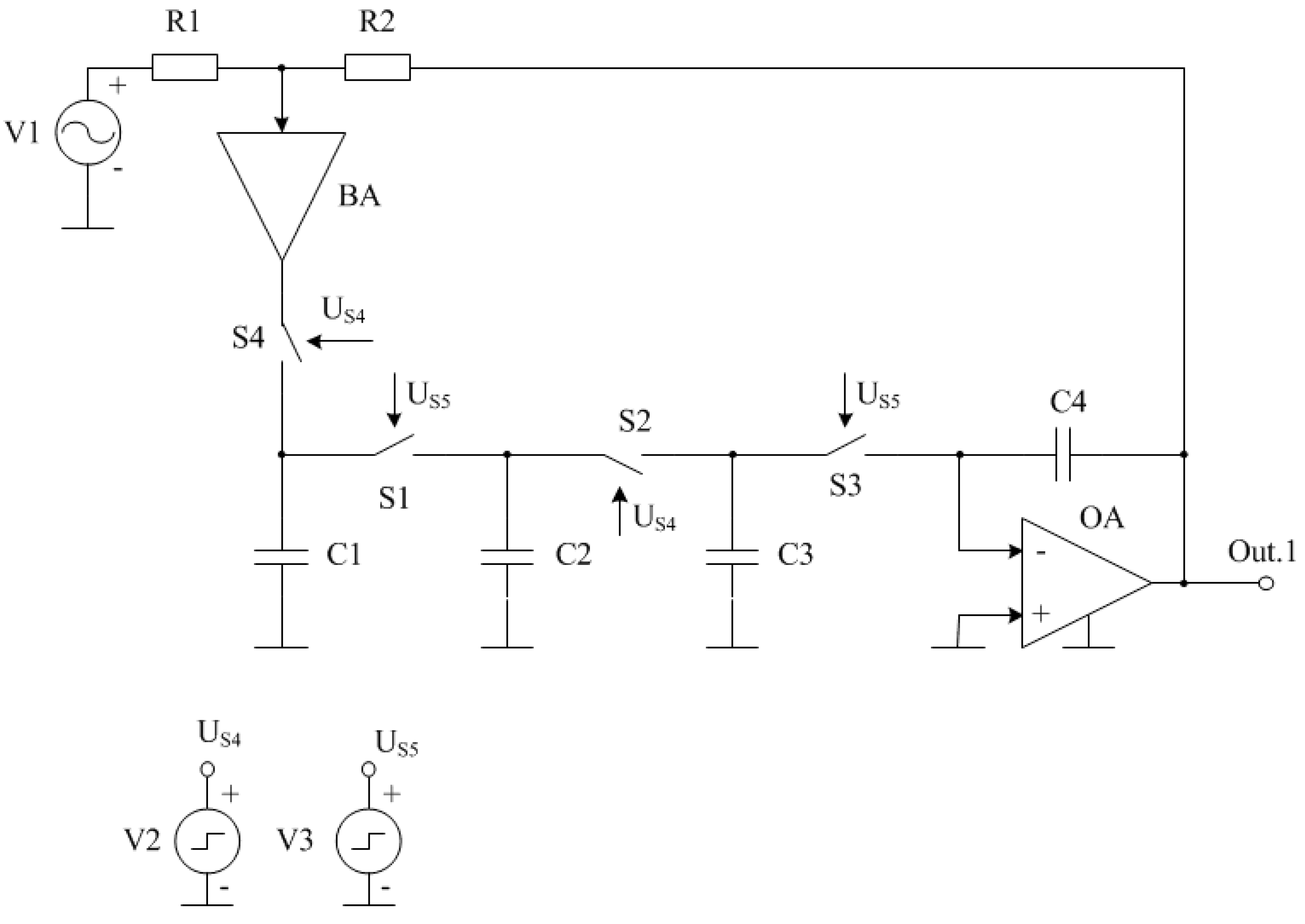
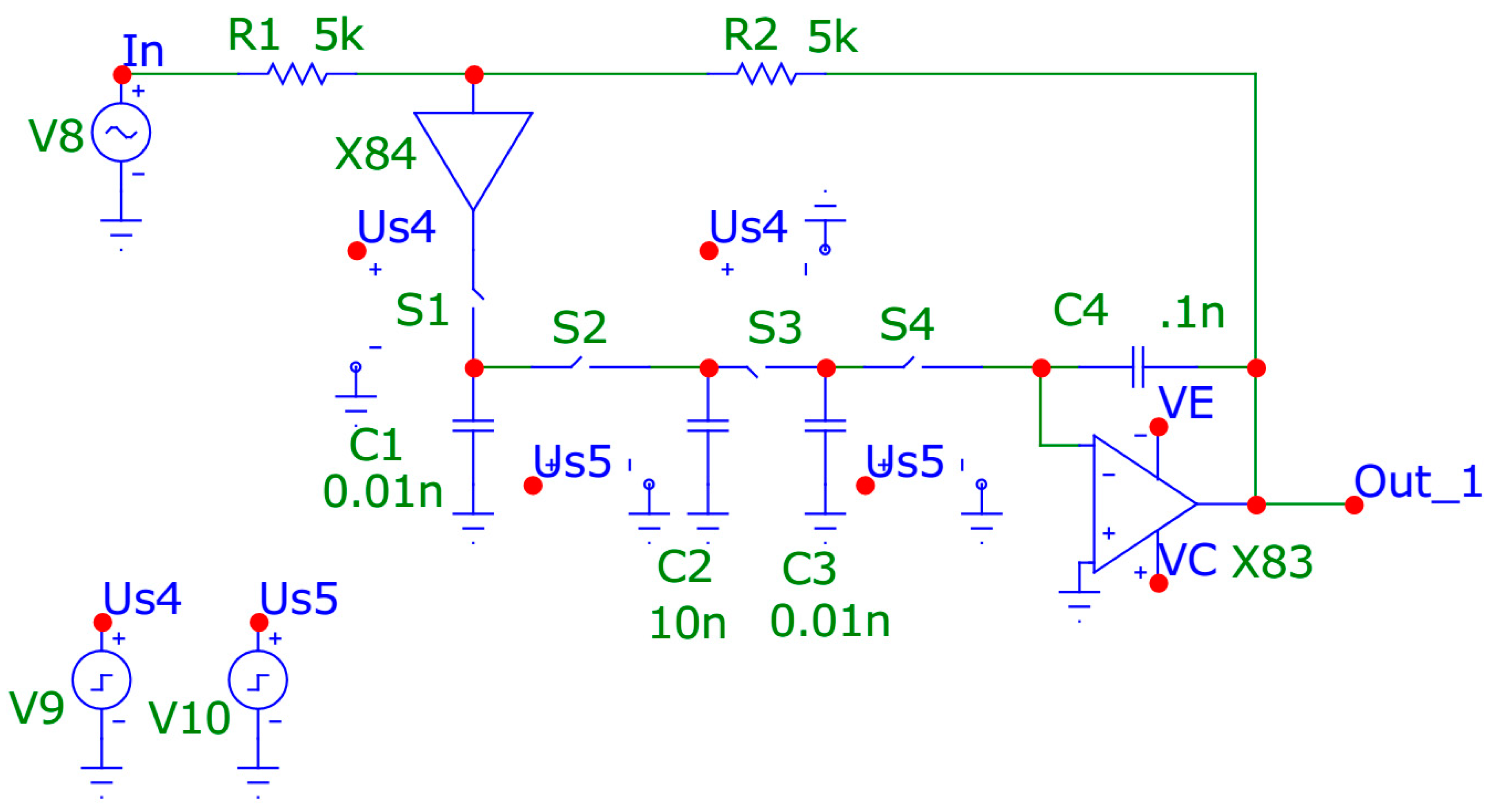
Figure 3.
Control signals of DAF electronic keys (Figure 1).
Figure 3.
Control signals of DAF electronic keys (Figure 1).
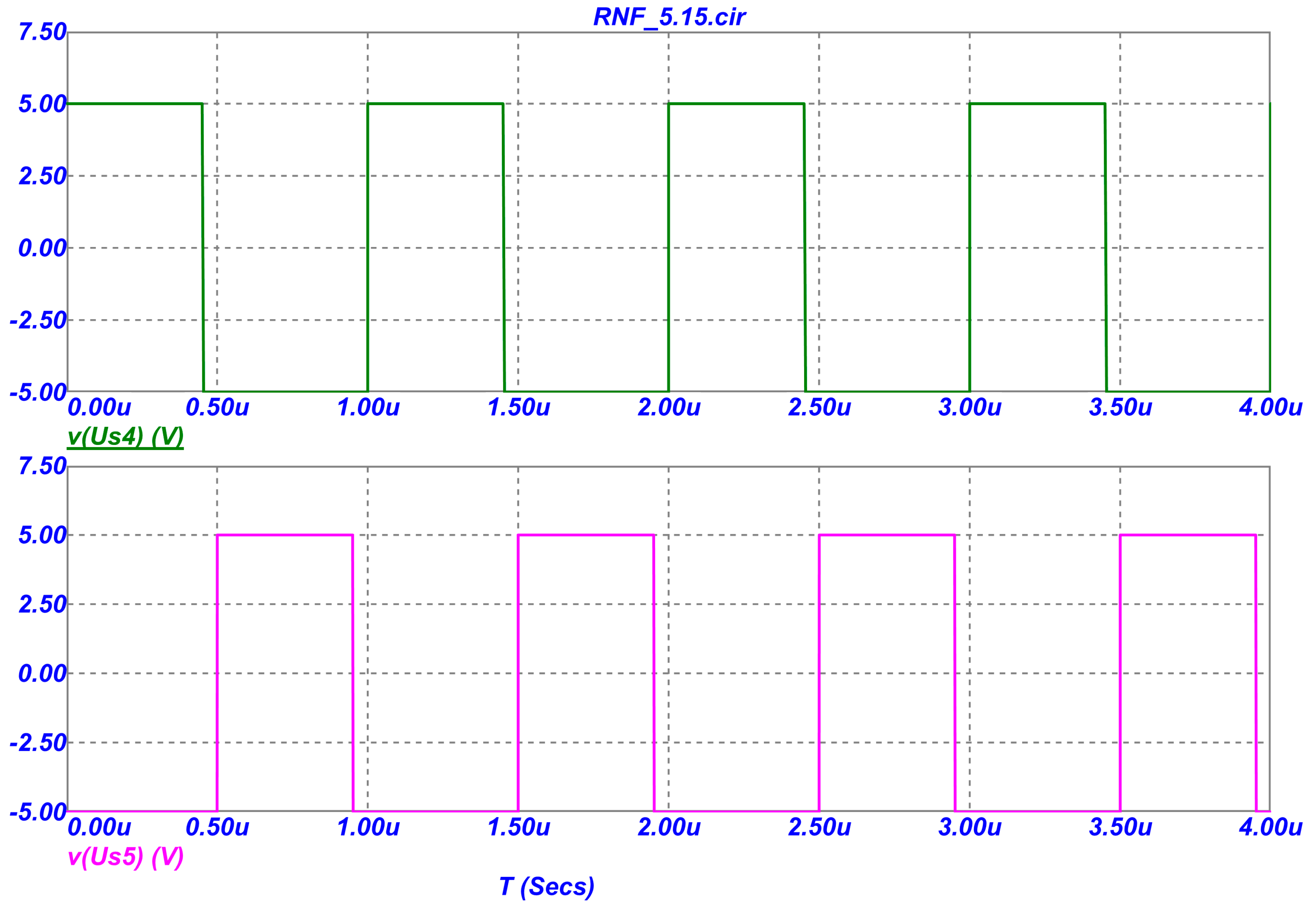
Figure 4.
Oscillograms of the input and output signals of the DAF (Figure 2).
Figure 4.
Oscillograms of the input and output signals of the DAF (Figure 2).
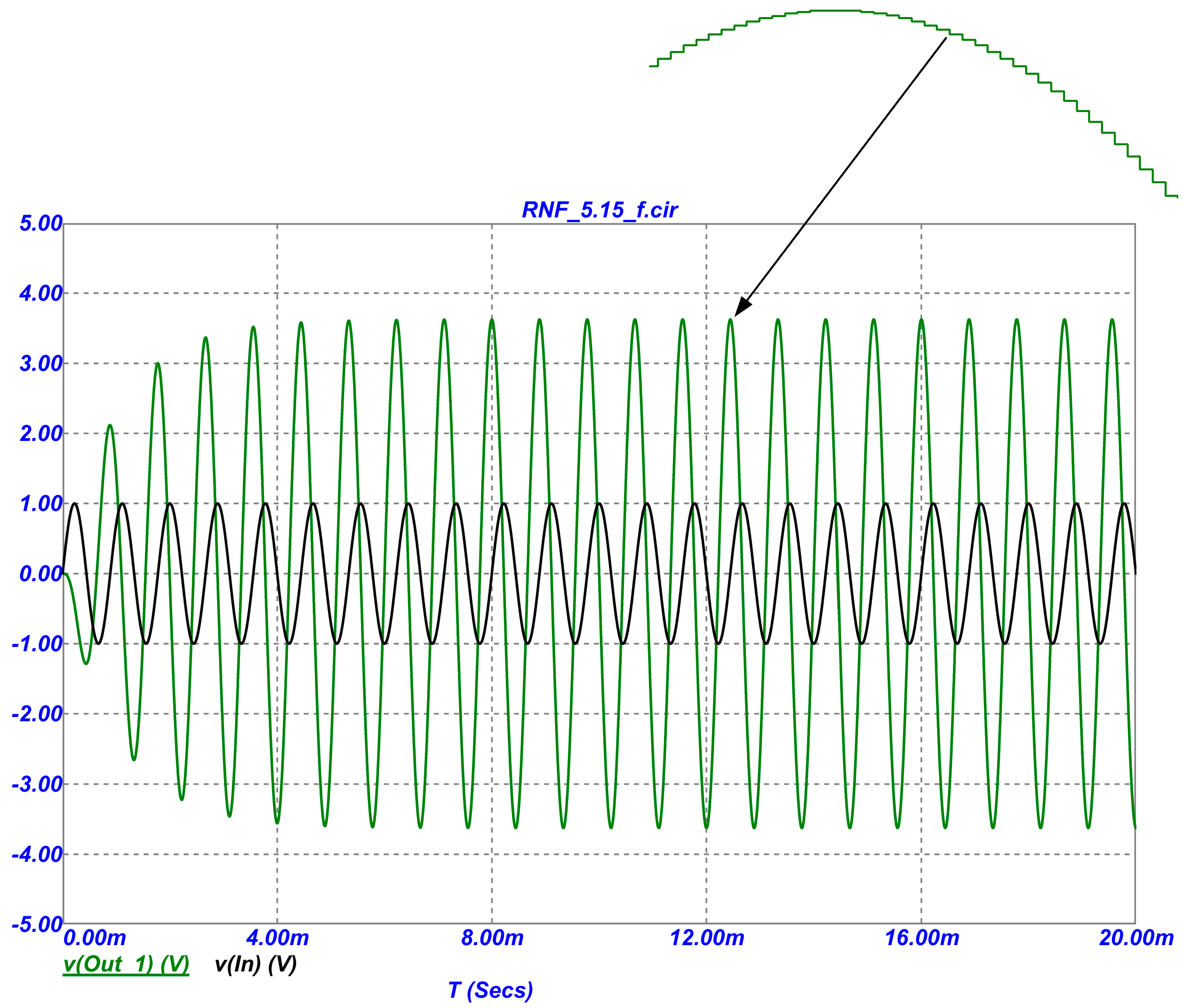
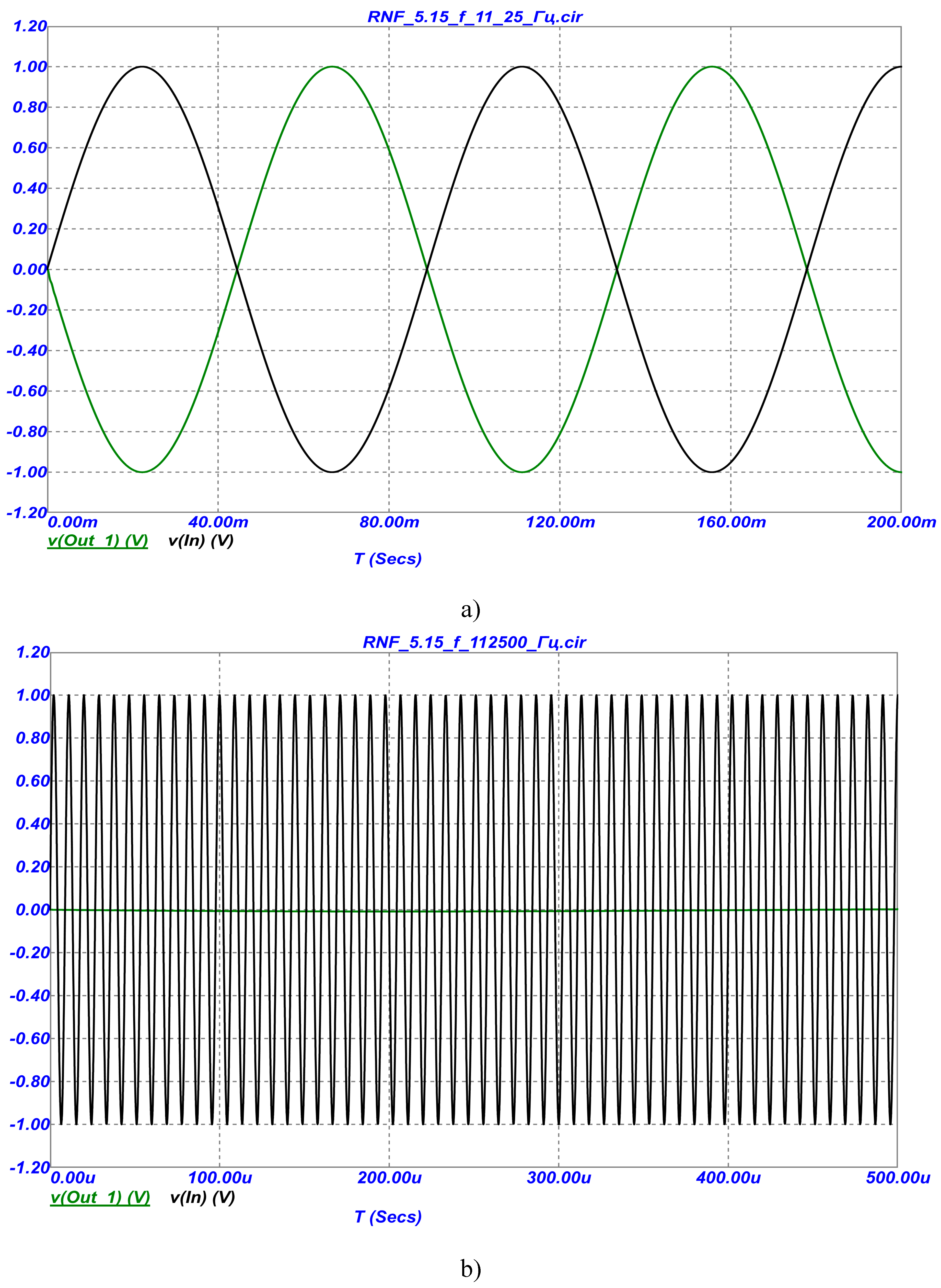
Figure 5.
Oscillograms of the input and output signals of the DAF in the range of very low (100 times lower than the pole frequency) (a) and high (100 times higher than the pole frequency) (b).
Figure 5.
Oscillograms of the input and output signals of the DAF in the range of very low (100 times lower than the pole frequency) (a) and high (100 times higher than the pole frequency) (b).
Disclaimer/Publisher’s Note: The statements, opinions and data contained in all publications are solely those of the individual author(s) and contributor(s) and not of MDPI and/or the editor(s). MDPI and/or the editor(s) disclaim responsibility for any injury to people or property resulting from any ideas, methods, instructions or products referred to in the content. |
© 2023 by the authors. Licensee MDPI, Basel, Switzerland. This article is an open access article distributed under the terms and conditions of the Creative Commons Attribution (CC BY) license (http://creativecommons.org/licenses/by/4.0/).
Copyright: This open access article is published under a Creative Commons CC BY 4.0 license, which permit the free download, distribution, and reuse, provided that the author and preprint are cited in any reuse.


