
Submitted:
05 February 2026
Posted:
06 February 2026
You are already at the latest version
Abstract
The autonomous grasping of flexible slings is a pivotal challenge for unmanned crane systems, primarily stemming from the slings' geometric indeterminacy, material compliance under load,and stochastic initial pose relative to the hook.To address this challenge,we propose an intelligent hook system featuring a novel compound mechanical architecture.This architecture integrates a horizontal slewing mechanism for in-plane alignment with a self-locking worm-gear drive for secure grasping.A coordinated control strategy,employing a Fuzzy PID algorithm,ensures robust dynamic performance under variable loading conditions.Finite element analysis confirms structural integrity under a rated load of 500 kg,with a maximum stress of 344.34 MPa.Experimental results demonstrate that the hook completes a full pick-and-release cycle in approximately 2 seconds for parallel slings, with a success rate exceeding 95%.This represents an approximately 60% improvement in operational efficiency over manual operation.This work provides a practical and efficient solution for automating flexible sling handling.
Keywords:
rotating mechanism
; intelligent hook
; mechanical structure
; control system
; fuzzy PID control
; finite element analysis
1. Introduction
The automation of lifting and handling operations represents a critical frontier for enhancing efficiency,safety,and operational predictability within modern industrial logistics and manufacturing [1].This is particularly relevant for handling irregular,bulk,or loosely packaged materials,where flexible sling—such as synthetic roundslings and textile belts—are indispensable due to their versatility and favorable load distribution.However,the transition to fully autonomous hooking and unhooking of these compliant loads remains a significant engineering challenge.The core difficulty arises from three inherent problems:the geometric indeterminacy of the sling,its material compliance (leading to dynamic shape deformation),and the stochastic spatial relationship between the hook and sling at the moment of engagement.These factors collectively pose significant obstacles to reliable automated alignment,introduce safety hazards due to mis-hooking,and limit the deployment of unmanned crane systems in complex material-handling scenarios.
Current research and development efforts targeting these issues reveal a fragmented landscape.A well-established body of work focuses on enhancing conventional hook systems through advanced finite element analysis for topological optimization [2] and integrating sensor networks for real-time health monitoring [3].While crucial for enhancing intrinsic safety,these approaches remain within the paradigm of a static hook geometry and fail to address the need for autonomous posture adaptation.Parallel efforts in mechanization have produced motor-driven mechanisms that automate the opening and closing of the hook latch [4].Designs of automated hooking systems have been explored to reduce manual intervention [5].Yet,such mechanisms typically assume a predetermined,vertically aligned approach trajectory and lack inherent spatial reorientation capability,rendering them ineffective when the initial hook-sling configuration is non-vertical.More recent work seeks to integrate perception-driven guidance,primarily using machine vision to identify sling pose [6].A persistent shortcoming of this approach,however,is the frequent decoupling between perceptual sensing and physical actuation.These systems often lack a tightly integrated mechanical actuator capable of executing the precise spatial adjustments identified by perception.
A critical synthesis identifies a persistent adaptation gap:a lack of integrated systems that seamlessly couple real-time perception with a mechanically responsive structure to achieve reliable grasping under all orientations.Structural optimizations do not confer adaptive intelligence, mechanized hooks are geometrically inflexible,and perception-based systems are often crippled by an execution layer incapable of spatial adaptation.Consequently,there is a compelling need for a new class of intelligent lifting device that embodies the co-design of kinematics,control, and perception to autonomously execute a holistic "perceive-align-engage-lock" sequence.
In response,this paper presents the design, implementation, and validation of a novel Horizontal Rotating Intelligent Hook.The primary contributions are threefold.First,we introduce a compound mechanical architecture that synergistically combines a worm-gear-driven grasping mechanis—providing fail-safe,power-off self-locking—with an independently actuated slewing mechanism.This dual-degree-of-freedom design fundamentally decouples the hook's alignment rotation from its grasping function,enabling posture adaptation to a wide range of sling orientations [7].Second,we develop and validate a Fuzzy PID control strategy for the servo-driven systems.Comparative simulation and experimental analysis demonstrate its superior performance in managing system nonlinearities and disturbances,outperforming conventional PID controllers in settling time and trajectory tracking accuracy [8].Third,we detail the development of a fully functional prototype centered on an STM32 microcontroller and conduct Extensive experiments.Performance benchmarking against manual operation and a non-rotating automated hook quantitatively verifies the system's high operational efficiency,success rate across diverse angles,and practical advantage in automating flexible sling handling.
2. Materials and Methods
2.1. Structural Design Scheme and Overall Improvements
To address the critical challenges in automated flexible sling handling—specifically alignment difficulties,safety hazards,and the limited adaptability of conventional hooks—this study presents an intelligent hook featuring horizontal slewing and adaptive grasping capabilities.The overall architecturez comprises an external protective housing and internal functional modules.The design workflow follows a systems engineering approach from requirement analysis to detailed design,as illustrated in Figure 1.
Compared to traditional hooks,this design incorporates three major improvements.First,functional actuation is introduced,Traditional hooks are entirely passive,relying on the gross motion of the crane and manual operation for all alignment and grasping actions.This design integrates a drive system, empowering the hook to execute grasping and releasing actions autonomously.Second, pose adaptability.Traditional hooks have a fixed orientation and cannot handle initial scenarios where the sling is parallel to the hook plane.This design introduces an independent horizontal slewing degree of freedom,enabling the hook to actively adjust its own azimuth for omnidirectional alignment.Third,integrated safety.Traditional hooks depend on additional safety devices such as mechanical latches.This design leverages the inherent self-locking property of the worm-gear transmission to integrate the safety mechanism directly into the core drive train,achieving fail-safe, power-off self-locking.These improvements transform the hook from a static tool into an intelligent end-effector with preliminary environmental interaction capabilities.
2.2. Drive Mechanism Design
The drive system of the intelligent hook is responsible for providing the power required for the grasping action.To ensure smooth and controllable operation,an MD57AIS61-24-C00510-B1-14-1-R DC servo motor is selected [9],with a rated voltage of 24 V and a rated torque of 0.72 N·m.This motor drives the rotation of the hook shaft via the transmission mechanism,thereby controlling the opening and closing of the hook body.
The selection of an energy source is a critical design consideration.The design requires the hook to complete one automatic pick-and-release cycle within 2 seconds and operate continuously for 2,000 cycles.Based on the rated parameters, the power consumption is estimated,and the minimum required battery capacity is determined as:
Based on this calculation and considering factors such as battery aging,temperature effects,and installation space,a rechargeable lithium-ion battery pack with a capacity of 2600 mAh is ultimately selected as the power supply.This drive scheme ensures sustained and stable autonomous operation of the intelligent hook,eliminating reliance on direct manual intervention.
2.3. Transmission Mechanism Design
The transmission mechanism serves as the critical interface between the drive system and the end-effector (hook body).Its core design requirements are efficient torque transmission,precise motion conversion,and guaranteed power-off safety—a feature absent in traditional hooks.Given the requirements for self-locking and a high transmission ratio,a worm-gear transmission mechanism is adopted in this design [10].
The selection of the transmission ratio must balance self-locking conditions,output torque,and response speed.Based on the required load torque and the motor's rated torque the preliminary ratio should satisfy where is the transmission efficiency.To ensure reliable self-locking, the worm lead angle must be less than the equivalent friction angle ,i.e.:
where: is the number of worm threads; is the module; is the worm reference diameter.
In this design,the maximum required load torque is 42.5 N·m, the motor rated torque is 0.72 N·m,taking and ≈69.4.To simultaneously meet self-locking (selecting =1) and structural compactness, the final ratio is set to =70.At this ratio,the lead angle =0.81,which is less than the material's friction angle,satisfying the self-locking requirement.The calculated output torque is 42.3 N·m,meeting the load demand.A matching worm wheel with tooth count is designed to interface with the hook shaft.
The worm gear and worm are fabricated via 3D printing using glass-fiber-reinforced polyamide (PA6 + 30% GF) and are coated with an alumina ceramic spray to enhance wear resistance.As the force-transmitting core,the hook spindle is made of 40Cr alloy steel,and its mechanical properties are shown in Table 1.To ensure safety,its allowable stress must be checked:
Where: represents the allowable stress of the hook shaft; denotes the yield limit of the material; is the safety factor.
With a safety factor of 1.5,the allowable stress is 456.11 MPa.Verification via static finite element analysis under full-load conditions (Figure 2) shows that the maximum stress on the hook spindle is 344.34 MPa,with a maximum deformation of only 0.047 mm,fully complying with the design standards and confirming the reliability and safety of the transmission system [11].
2.4. Slewing Mechanism and Overall Integration
To enable the hook to adapt to initial poses parallel to the flexible sling,an independent horizontal slewing mechanism is integrated into the design [12].This represents a fundamental innovation that distinguishes it from both traditional hooks and automated hooks with only opening/closing capabilities.This mechanism is driven by a high-precision servo motor with a rated voltage of 6.0-7.4 V, a stall torque of 1.47 N·m, and capable of precise angular control within a 180° range.
Given the servo motor's inherent self-locking capability and substantial output torque [13], a gear transmission scheme is adopted for the slewing mechanism.To optimize the structure, the pinion is selected with the minimum number of teeth to avoid undercutting, i.e.,z_min = 17.The hook's slewing angle is set to 90°,and the gear transmission ratio is configured as i_g = 2, resulting in a driven gear tooth count of z₂ = 34.The slewing shaft (material Q345),which connects the crane's wire rope to the hook body,has mechanical properties listed in Table 2. Static analysis results (Figure 3) indicate that under the combined load of the hook's self-weight and the rated payload, the maximum equivalent stress on the slewing shaft is 188 MPa,with a maximum deformation of 0.03 mm, verifying its structural integrity.
Finally,the mechanical system of the intelligent hook achieves a high level of integration,with its internal structure depicted in Figure 4.First,the slewing motion:The rotary steering gear (Component 9) drives the pinion,which engages with the large rotary gear ring (Component 10) fixed to the housing,causing the entire lower assembly to rotate horizontally about the main bearing (Component 8).Second,grasping and self-locking: The DC motor (Component 1) transmits torque via a coupling (Component 2) to the worm (Component 3),which meshes with the worm wheel (Component 4) fixed to the hook spindle (Component 5),thereby actuating the hook body (Component 7) for opening and closing.The inherent reverse self-locking property of the worm-gear pair ensures that the hook remains securely locked under load even when the motor is powered off.The control board and battery compartment (Component 11) are housed within the main housing (Component 12).This design,which decouples and integrates the two major functions of horizontal alignment and vertical grasping both mechanically and in the control system,forms the physical foundation enabling the intelligent hook to autonomously complete the entire sequence of "perceive-align-engage-lock" operations.
3. Modeling and Fuzzy PID Control Simulation Analysis of the Intelligent Hook
3.1. Modeling of the Intelligent Hook
Following the mechanical design of the intelligent hook,a detailed mathematical model is formulated to characterize the relationship between the hook’s rotation angle and the motor’s motion.The derivation proceeds as follows:
During system modeling,the armature voltage is designated as the control input.Based on Kirchhoff’s voltage law,the voltage balance equation for the armature circuit is established as:
In the formula: is the DC motor armature voltage; is the armature current; is the armature resistance; is the motor inductance; is the motor back electromotive force (back-EMF),where ,and is the back-EMF constant.
According to the torque balance equation of the motor,the relationship is expressed as follows:
In the formula: is the output torque of the motor,where ,and is the motor torque constant; is the moment of inertia of the motor shaft after reduction through the worm gear transmission; is the friction coefficient of the motor shaft rotational speed.
If the rotation angle of the motor output shaft is θ1,then ,by substituting into Formula (4),the following expression can be obtained:
Since the armature inductance of the DC motor is very small,it is considered negligible in the practical control model.By combining Equation (3) and Equation (5),the dynamic equation of the motor can be derived as:
If the rotation angle of the intelligent hook is θ2 and the transmission ratio is i=70,where θ1=iθ2,substituting this into Equation (6) yields the differential equation relating the rotation angles of the intelligent hook and the motor:
To validate the accuracy of the mathematical model,a simulation model was implemented in MATLAB/Simulink.A step input of 24 V armature voltage was applied,and the corresponding rotation angle response of the hook was simulated.The simulation results were subsequently compared with experimental data, in which the actual hook rotation angle was measured using an encoder. As shown in Figure 5,the maximum discrepancy between the simulated and experimental rotation angles is 2.3°,corresponding to an error rate below 3%.These results confirm that the model effectively captures the dynamic relationship between the motor input voltage and the hook’s rotational displacement.
The observed correlation between the intelligent hook's angular displacement and the motor input voltage—where angle variations consistently follow voltage chang—theoretically validates the electromechanical mechanism enabling precise positional control via motor actuation.
3.2. Simulation Analysis Based on Fuzzy PID Control
To verify the superiority of the proposed fuzzy PID control strategy,a simulation model of the intelligent hook servo drive system was built in MATLAB/Simulink [14,15]. The system transfer function is based on Eq. (7).The traditional PID controller parameters are: , , .The fuzzy PID controller takes the angle error and error change rate as inputs and adjusts online via a designed fuzzy rule table. Figure 6 and Figure 7 respectively present the comparative response curves of the fuzzy PID and traditional PID controllers for step inputs and sinusoidal trajectory tracking [16,17,18].The simulation results indicate that for the step response,the fuzzy PID controller achieves a significantly reduced overshoot of only 8.5%—representing a 61.5% improvement over the 22.1% overshoot of the traditional PID—along with an approximately 40% reduction in settling time.Furthermore,in trajectory tracking,the fuzzy PID controller reduces the root mean square error (RMSE) by about 35% compared to the conventional method,demonstrating enhanced anti-interference capability and superior robustness.
Figure 8 further illustrates the anti-disturbance performance of both controllers when subjected to a sudden load torque disturbance of 5 N·m at t = 2 s during steady-state operation.The fuzzy PID controller restores stability within 0.15 s and exhibits a smaller angular fluctuation amplitude compared to the traditional PID controller.These simulation results conclusively demonstrate that the designed fuzzy PID controller effectively accommodates system nonlinearities and load variations,outperforming the conventional PID approach in both dynamic response and steady-state stability,thereby providing a solid theoretical foundation for subsequent physical implementation.
4. Control System Design of the Intelligent Hook
4.1. Remote Control Section of the Intelligent Hook
The prototype of the intelligent hook consists of an execution unit—comprising the mechanical structure and servo drive—and a handheld remote control unit. The remote is equipped with a three-button interface (power, lift, lower) and communicates wirelessly over a local network, operating reliably within a temperature range of −20 °C to 40 °C.The system control is centered on an STM32F103 microcontroller, which interfaces directly with the servo motor encoder via an integrated Controller Area Network (CAN) bus.A 1.3-inch Organic Light-Emitting Diode (OLED) display is integrated to provide real-time status feedback to the operator.
Figure 9 illustrates the hardware connections of the system.The human–machine interface (HMI) of the remote unit is implemented via the General-Purpose Input/Output (GPIO) pins of a Raspberry Pi,incorporating two control buttons, a display screen,and status indicator Light-Emitting Diodes (LEDs).Communication between the remote (master) and the hook assembly (slave) is established through a wireless module based on the Transmission Control Protocol/Internet Protocol (TCP/IP) Socket protocol.This configuration ensures the reliable transmission of parsed button commands from the remote to the STM32F103-based receiver unit [19].
The Transmission Control Protocol/Internet Protocol (TCP/IP) Socket protocol was selected due to its balanced performance across several key requirements:its connection-oriented architecture ensures reliable,in-order command delivery in industrial wireless environments,effectively mitigating packet-loss-induced failures;it offers broad compatibility with existing industrial Local Area Networks (LANs) and embedded systems,enabling straightforward integration and future expansion such as data reporting;mature Socket libraries on both STM32 and Raspberry Pi platforms streamline development and improve stability;and despite its general-purpose design,the low data volume of hook control commands allows TCP/IP latency in a LAN to meet millisecond-level real-time response demands.Together,these attributes—reliability,compatibility,development efficiency,and real-time suitability—make TCP/IP Socket a well-founded choice for the wireless control link in the intelligent hook system.
4.2. Overall Control Flow
The intelligent hook is equipped with two control buttons and three status indicators,all located on the same side of the hook housing for convenient operator access.Button A serves as the start button,which powers on the control system and is accompanied by illumination of the power indicator (Indicator 1).Button B functions as the stop button to cut off system power.Commands are transmitted from the remote control unit (End A) to the hook assembly (End B) via wireless communication.Signal 1 triggers forward motor rotation to open the hook,with the opening indicator (Indicator 2) activated until the hook reaches the 90° horizontal position.Conversely,Signal 2 commands reverse motor rotation to close the hook, during which the engagement indicator (Indicator 3) remains lit until closure is completed.To prevent potential damage from erroneous commands,an initial-position monitoring function verifies the hook’s current state before executing any movement.The detailed control logic is illustrated in Figure 10.
Upon completion of a lifting operation, pressing Button A again resets the control system automatically,preparing it for the next cycle.
5. Physical Experiment Verification and Performance Analysis
5.1. Remote Lifting and Self-Locking Experiment of the Intelligent Hook
A laboratory-based remote-control experiment was performed to validate both the functional integrity of the intelligent hook’s mechatronic control system and the performance superiority of the implemented fuzzy PID control algorithm [20,21].Under simulated field conditions—with the hook suspended by a wire rope—commands were issued via the remote unit,successfully executing a complete operational cycle:system startup,lifting and rotation to the 90° horizontal position with reliable motor-cutoff self-locking,and a smooth return to the closed position.The process exhibited consistent responsiveness,positional accuracy, and operational stability.The results confirm effective remote operability,dependable mechanical self-locking,and smooth motion transitions,thereby verifying both the correctness of the control program and the efficacy of the fuzzy PID algorithm.Synchronized real-time status indication through LED lights provided clear visual feedback of the system workflow,as illustrated in Figure 11.
5.2. Experiment on Hooking Flexible Slings in Parallel Position
The flexible sling and the intelligent hook were arranged in a parallel configuration as shown in Figure 12.
The hook and sling are in a parallel configuration, simulating a common real-world misalignment scenario that conventional hooks cannot handle autonomously.
A control signal was sent to the intelligent hook's terminal,simulating the output of a vision-based recognition system upon detecting the relative angle between the flexible sling and the hook.In response,the hook initially opened,followed by a 90° rotation of its slewing mechanism to achieve vertical alignment for engagement,as shown in Figure 13.
The hook autonomously rotates 90°,achieving perpendicular alignment with the sling and demonstrating the core adaptive capability of the slewing mechanism.
Subsequently,the neodymium magnets positioned beneath the intelligent hook attract the magnetic elements integrated into the flexible sling,thereby achieving full automated engagement between the hook and the sling.As shown in Figure 14,the hook successfully completed the automated grasping sequence,which validates the effectiveness of the integrated‘slew-and-grasp’workflow when confronting parallel alignment challenges.
Following the alignment in Figure 13, the hook successfully grasps the sling via integrated magnetic assistance,completing the "perceive–align–engage" sequence.
5.3. Performance Comparison Experiment Design
To quantitatively assess the performance advantages of the proposed intelligent hook,a comparative experimental scheme was designed.The experimental group utilized the proposed intelligent hook with an integrated slewing mechanism.Control group 1 consisted of traditional manual operation performed by an experienced worker,while control group 2 utilized an automated hook with only vertical lifting/lowering capabilities and no slewing function,representing existing automated solutions.The test required the completion of 10 pick-and-hang cycles for three typical hook-to-sling angles:0° (vertical), 45°,and 90° (parallel).Performance was evaluated based on the average cycle time,success rate,and maximum positioning error per operation.The detailed experimental results are presented in Table 3.
Based on the results presented in Table 3,it can be concluded that the proposed intelligent hook achieves efficient and reliable automated pick-and-hang operations across varying angles.The data quantitatively shows that in the challenging 45° and 90° configurations,our hook maintains a high success rate of 95% and 92%,respectively.In stark contrast,the non-slewing automated hook fails completely (0% success rate) under the same conditions.In particular,it demonstrates significant advantages in these non-vertical configurations.In contrast, traditional manual operation proves inefficient and labor-intensive. These findings validate both the necessity and effectiveness of integrating a slewing mechanism to enable full-pose adaptive handling of flexible slings,thereby substantially advancing the automation capability and operational adaptability of lifting systems.
5.4. Control Performance Experiment Under Different Loads
To validate the robustness of the control system under varying load conditions,angle step-response experiments were performed for a 90° rotation command under no-load,half-load (250 kg),and full-load (500 kg) scenarios.The corresponding results are presented in Figure 15.
The angle step response curves under no-load,half-load, and full-load conditions verify the effectiveness and stability of the proposed Fuzzy PID controller across the entire operational range.
5.5. Engineering Application Analysis and Prospects
Building on the experimental verification, the developed intelligent hook prototype demonstrates significant potential for addressing the core challenges of automated flexible sling handling.Its transition to practical engineering applications hinges on the construction of a "perception-decision-execution" closed-loop system deeply integrated with existing industrial infrastructure.The complete engineering system architecture,illustrated in Figure 16,builds upon the current prototype by integrating high-precision vision/lidar sensing modules to enable real-time 3D pose recognition of slings in complex industrial environments.A central controller (based on an STM32 or industrial PLC) computes the optimal operational path from the perceptual data and executes precise motion control by invoking the fuzzy PID algorithm detailed in Section 3 of this work.Concurrently,communication with upper-level hosts (e.g., crane control systems or Terminal Operating Systems (TOS)) via industrial Ethernet or CAN bus facilitates command reception and status reporting,forming a seamless, integrated operational loop.
6. Conclusion
This paper presented the design and implementation of a horizontal-slewing intelligent hook for the automated handling of flexible slings.The main conclusions are summarized as follows:(1) The proposed worm-slewing compound mechanical architecture effectively addresses the automation challenge posed by flexible slings,which lack fixed gripping points and exhibit random poses.The worm drive ensures safe, power-off self-locking,while the slewing mechanism provides essential posture adaptation.(2) Simulations of the fuzzy PID control strategy confirm its superior dynamic performance over conventional PID,contributing to stable and responsive system operation.(3) Physical experiments and comparative analyses show that the intelligent hook achieves a success rate above 92% in non-vertical pick-and-hang tasks,improves operational efficiency by over 60% compared to manual methods,and bridges a functional gap in existing automated hooks under such conditions.
Limitations and Future Work:The laboratory prototype developed in this study provides a feasible technical solution for automated flexible sling handling.Its transition to practical engineering applications necessitates the construction of a complete "perception-decision-execution" closed-loop (as illustrated in the conceptual diagram of Figure 16):the real-time pose of the sling is perceived through fusion perception combining machine vision and lidar;path planning and decision-making are performed by an on-board industrial computer;and precise grasping is ultimately executed by the electromechanical system designed in this paper.This system can be modularly integrated into equipment such as port container cranes and rail-yard gantry cranes.Upon deployment,it is expected to fundamentally eliminate the safety risks associated with manual hooking,standardize the single-operation cycle time,and provide a key equipment foundation for achieving all-weather unmanned material transfer.Subsequent work will focus on research into the anti-interference capability of perception algorithms in complex environments
References
- Wang, H; Yang, Q; Liu, Q. Automated productivity analysis of cable crane transportation using deep learning-based multi-object tracking. Automation in Construction 2024, 166105644–105644. [Google Scholar] [CrossRef]
- Yannan, Y; Zhiping, L; Yao, L. Optimal design of main girder structure of bridge crane based on equal life concept driven by data. Journal of Mechanical Science and Technology 2023, 37, 4767–4786. [Google Scholar] [CrossRef]
- Mingju, C; Zhongxiao, L; Zhengxu, D. HDS-YOLOv5: An improved safety harness hook detection algorithm based on YOLOv5s. Mathematical biosciences and engineering: MBE 2023, 20, 15476–15495. [Google Scholar] [CrossRef]
- Li, F; Qian, Y; Wu, S. A self-adapting trajectory tracking control for double-pendulum marine tower crane considering constraint dead zone against seawave disturbances. Ocean Engineering 2024, 309, 118358–118358. [Google Scholar] [CrossRef]
- Jiaqi, XU; Huixing, ZHOU; Jianming, GUO; et al. Structure Design and Control of a Remotely Controllable Automatic Hook. Science Technology and Engineering 2023, 23, 9927–9932. [Google Scholar]
- Jianbo, G; Yong, Q; Haibin, W. Research on Position Recognition System of Gantry Hoisting Based on Machine Vision. Integrated Ferroelectrics 2021, 219, 280–298. [Google Scholar] [CrossRef]
- Ding, W; Zhang, H; Hua, C. Deep reinforcement learning-based trajectory planning for double pendulum cranes: Design and experiments. Mechanical Systems and Signal Processing 2025, 234112780–112780. [Google Scholar] [CrossRef]
- Yang, X; Wu, D; Wang, C. Adaptive fuzzy PID control of high-speed on-off valve for position control system used in water hydraulic manipulators. Fusion Engineering and Design 2024, 203114437. [Google Scholar] [CrossRef]
- S. I P Model-Based Design of Microprocessor Control System for Direct Current Servo Electric Drive. Russian Electrical Engineering 2023, 94, 84–90. [CrossRef]
- Yu, P. Y M. E M Visualization of the Design Parameters of Worm Gears. Journal of Machinery Manufacture and Reliability 2023, 52, 367–374. [Google Scholar] [CrossRef]
- Tang, T; Wang, L; Zhu, M. Topology Optimization: A Review for Structural Designs Under Statics Problems. Materials (Basel, Switzerland) 2024, 17, 5970–5970. [Google Scholar] [CrossRef] [PubMed]
- A A I, R D Y. I D N Transmission and slewing mechanism for highly manoeuvrable small machine transmissions. Journal of Physics: Conference Series 2022, 2373. [Google Scholar] [CrossRef]
- Jing, H; Cheng, Q; Yanhui, Y. Intelligent Dynamic Force Loading Algorithm for Aerospace Rudder Load Simulator. Journal of Aerospace Engineering 2023, 36. [Google Scholar] [CrossRef]
- Lennert, R J; Fodor, D; Szalay, I. Development of an Automated Solution for the Error Analysis of MATLAB/Simulink-Based Digital Twins †. Engineering Proceedings 2025, 113, 49–49. [Google Scholar] [CrossRef]
- Yusre, M A F A; Samuji, A N S; Shari, M S N. Modeling and Simulation of AVR Systems in MATLAB/Simulink: Performance Comparison of PID and ANN Controllers. Journal of Power and Energy Engineering 2025, 13, 315–325. [Google Scholar] [CrossRef]
- Jiaxing, D. Performance comparison and analysis of traditional PID and fuzzy PID control applied to UAV. Journal of Physics: Conference Series 2023, 2649. [Google Scholar] [CrossRef]
- Guanggang, J; Lidong, Z; Mingyang, S. Enhanced variable universe fuzzy PID control of the active suspension based on expansion factor parameters adaption and genetic algorithm. Engineering Research Express 2023, 5. [Google Scholar] [CrossRef]
- Gómez, G R O; Navarro, Z A M; Sandoval, G P J. Heat exchanger control: Performance of thermodynamics-based geometrical vs classical PID controllers. Case Studies in Thermal Engineering 2025, 71106130–106130. [Google Scholar] [CrossRef]
- Nilnoree, S; Taparugssanagorn, A; Kaemarungsi, K. Enhancing Wireless Sensor Network in Structural Health Monitoring through TCP/IP Socket Programming-Based Mimic Broadcasting: Experimental Validation. Applied Sciences 2024, 14. [Google Scholar] [CrossRef]
- Li, W; Wei, X; Sun, D. Application of Hybrid SMA (Slime Mould Algorithm)-Fuzzy PID Control in Hip Joint Trajectory Tracking of Lower-Limb Exoskeletons in Multi-Terrain Environments. Processes 2025, 13, 3250–3250. [Google Scholar] [CrossRef]
- Oguzhan, K; Hasan, K. Design of robust fractional order fuzzy PID sliding mode controller based on hybrid swarm intelligence algorithm for a 6-DOF robotic manipulator. Robotica 2025, 43, 1110–1139. [Google Scholar] [CrossRef]
Figure 1.
Design process of the intelligent hook.
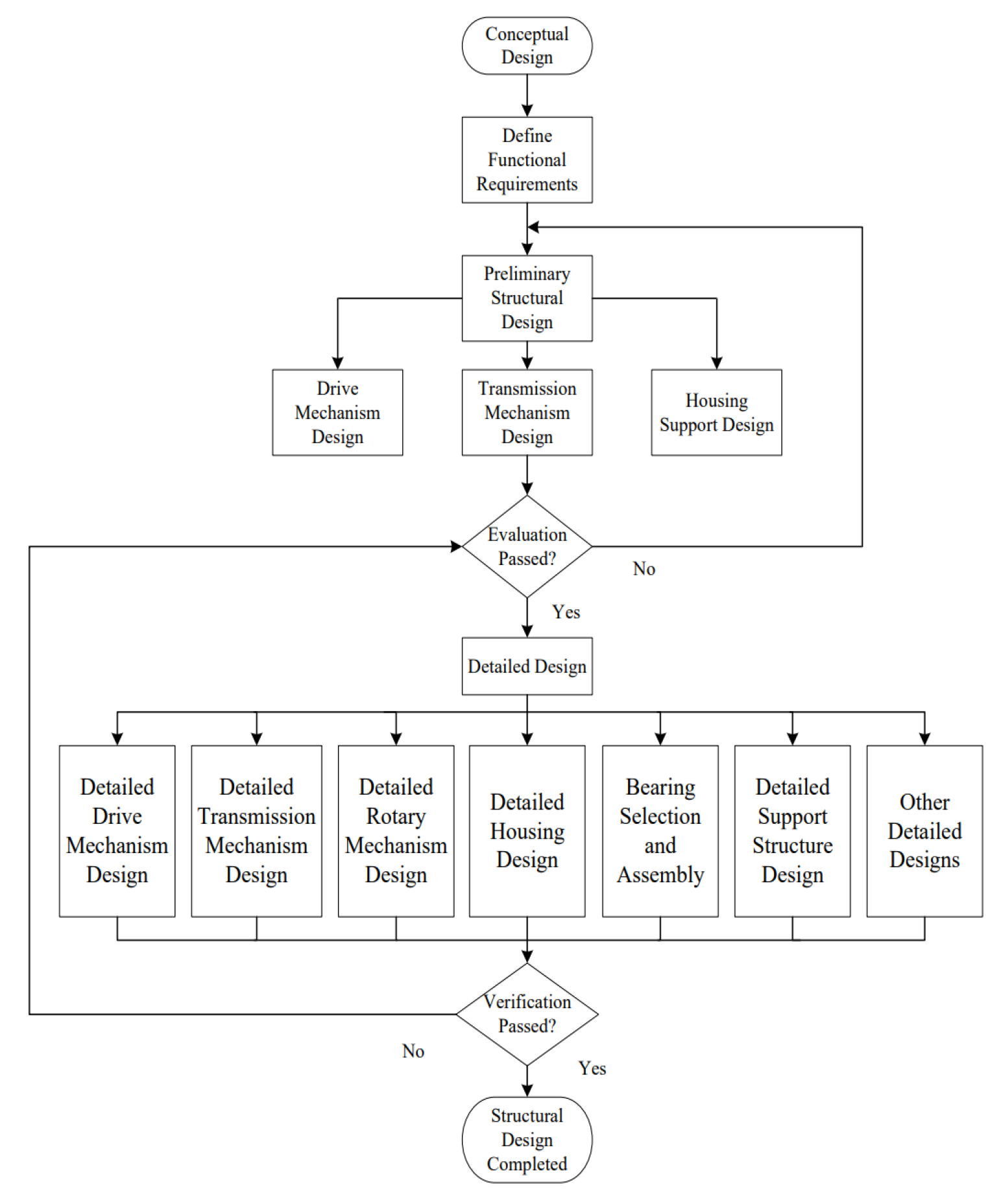
Figure 2.
Finite element analysis results of the hook shaft.
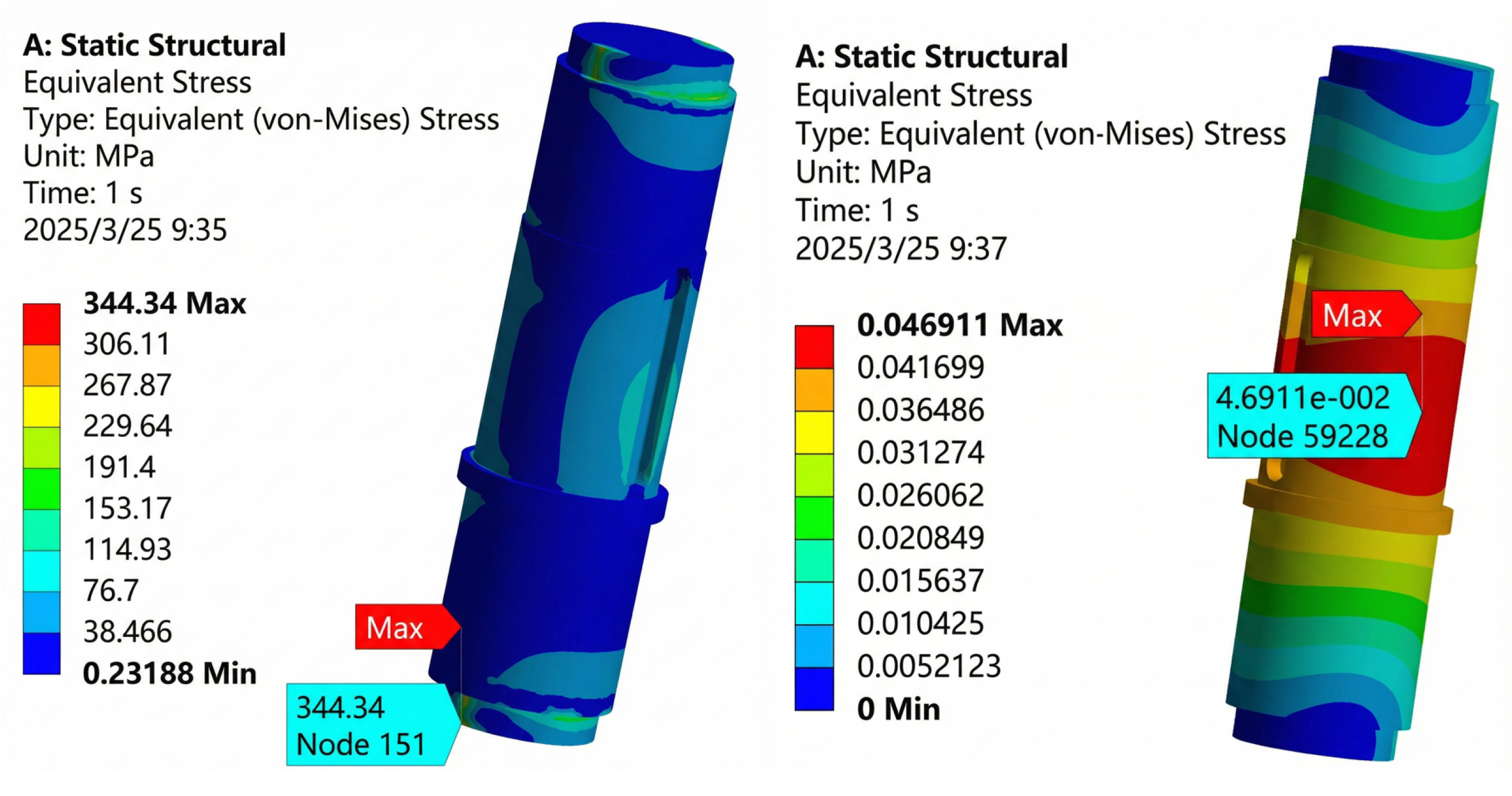
Figure 3.
Static analysis results of the slewing shaft.
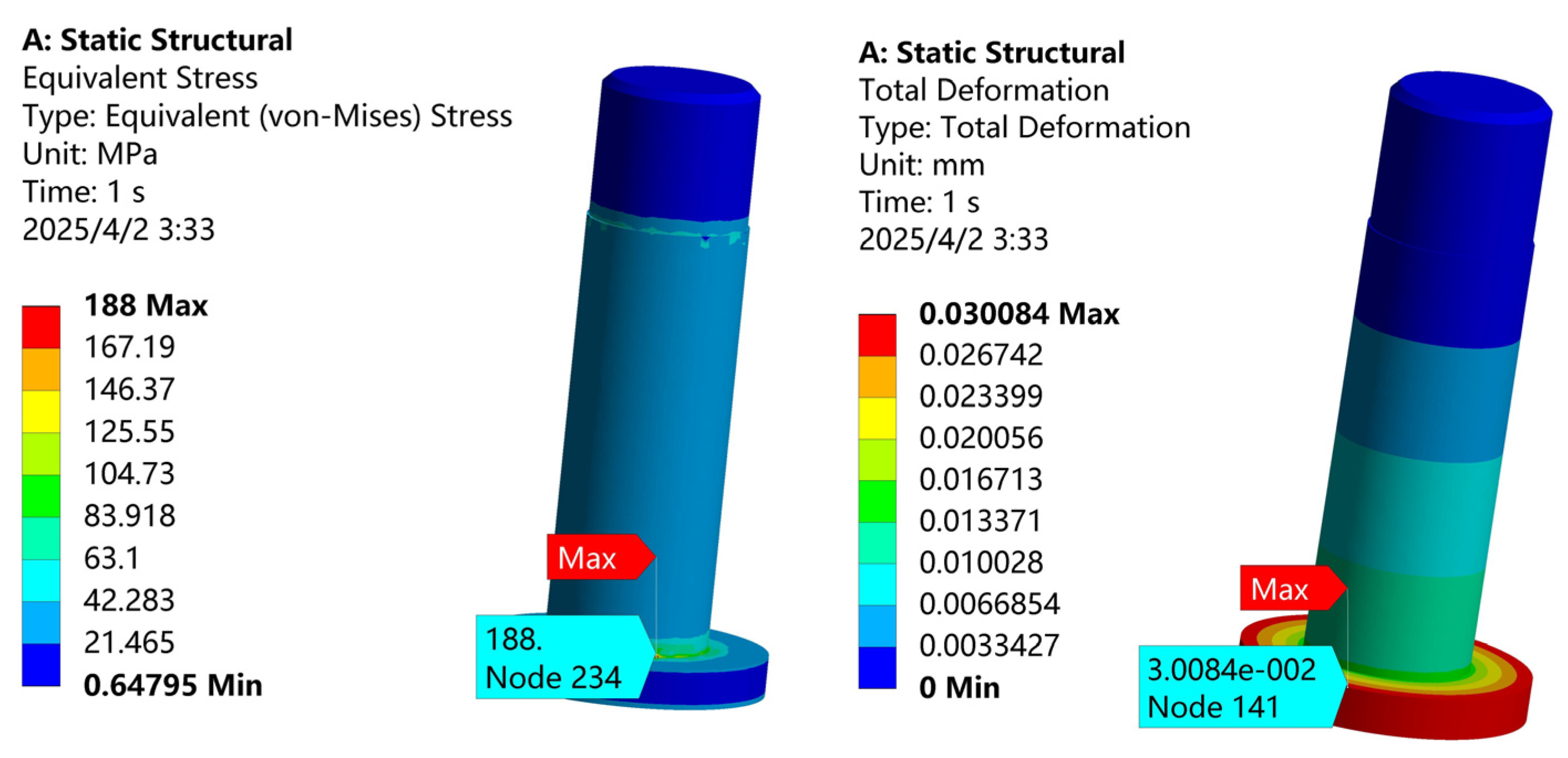
Figure 4.
Schematic diagram of the internal structure of the intelligent hook. (Labeling:1.DC motor;2.Coupling;3.Worm; 4.Worm wheel;5.Hook spindle;6.Main bearing support;7.Hook body (integrated magnet);8.Rotary large bearing;9.Rotary steering gear;10.Rotary gear ring;11.Control board and battery compartment location;12.Housing.).
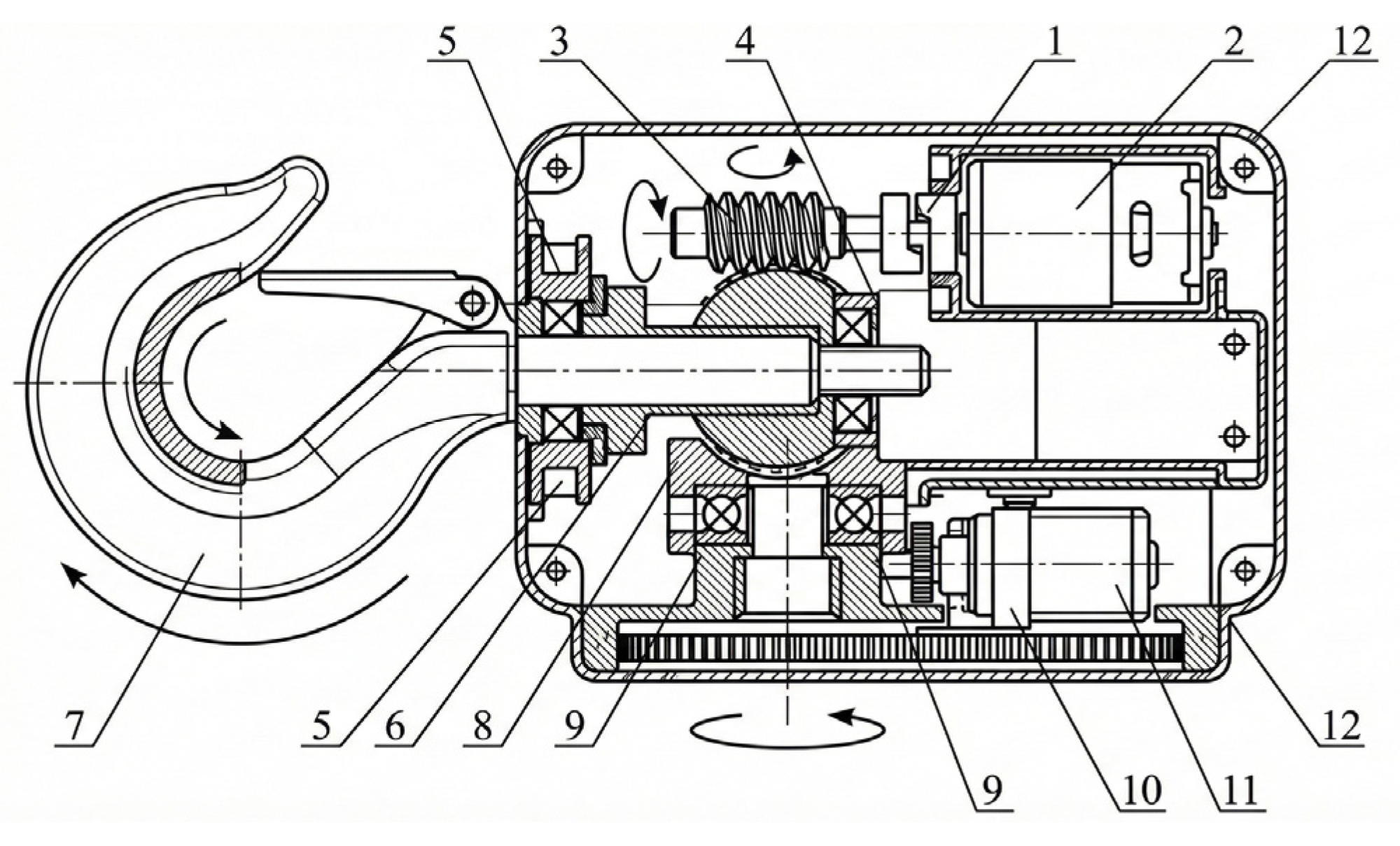
Figure 5.
Comparison curves of simulated and experimental rotation angles.
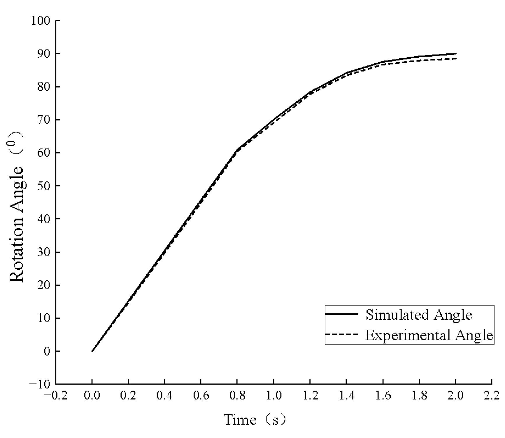
Figure 6.
Simulation comparison of step response between traditional PID and fuzzy PID controllers.
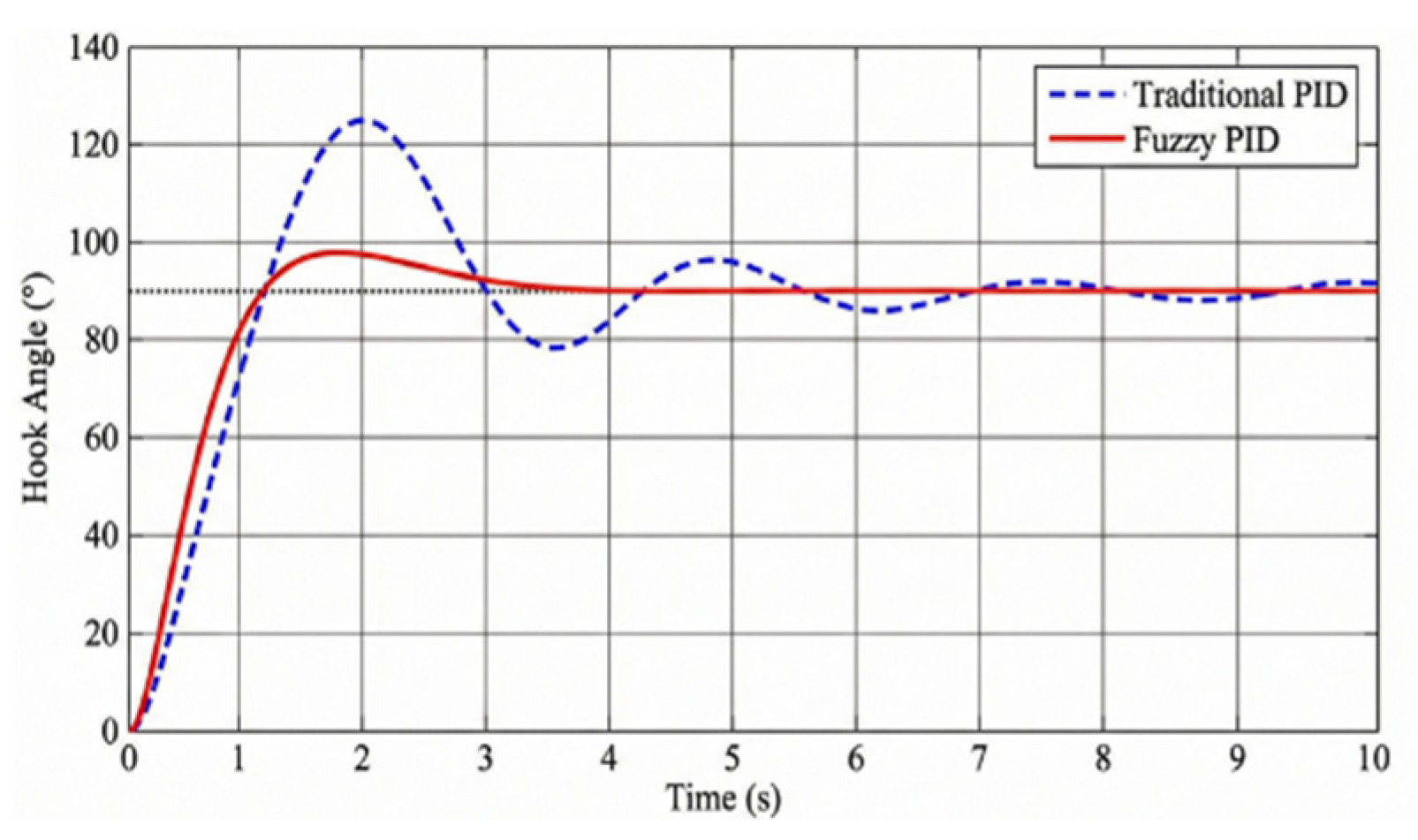
Figure 7.
Simulation comparison of sine trajectory tracking between traditional PID and fuzzy PID controllers.
Figure 7.
Simulation comparison of sine trajectory tracking between traditional PID and fuzzy PID controllers.
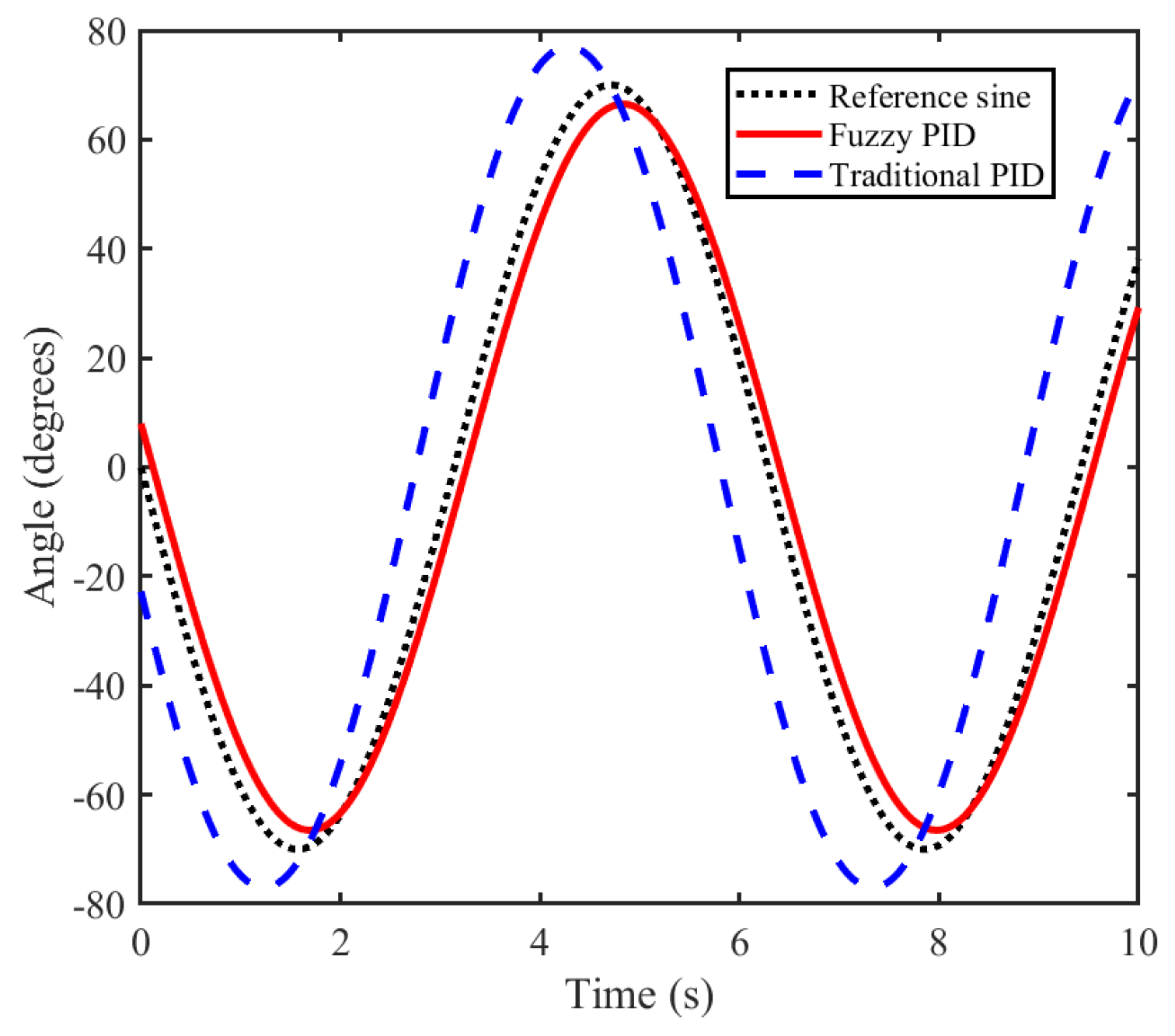
Figure 8.
Comparison of anti-interference performance under sudden load disturbance.
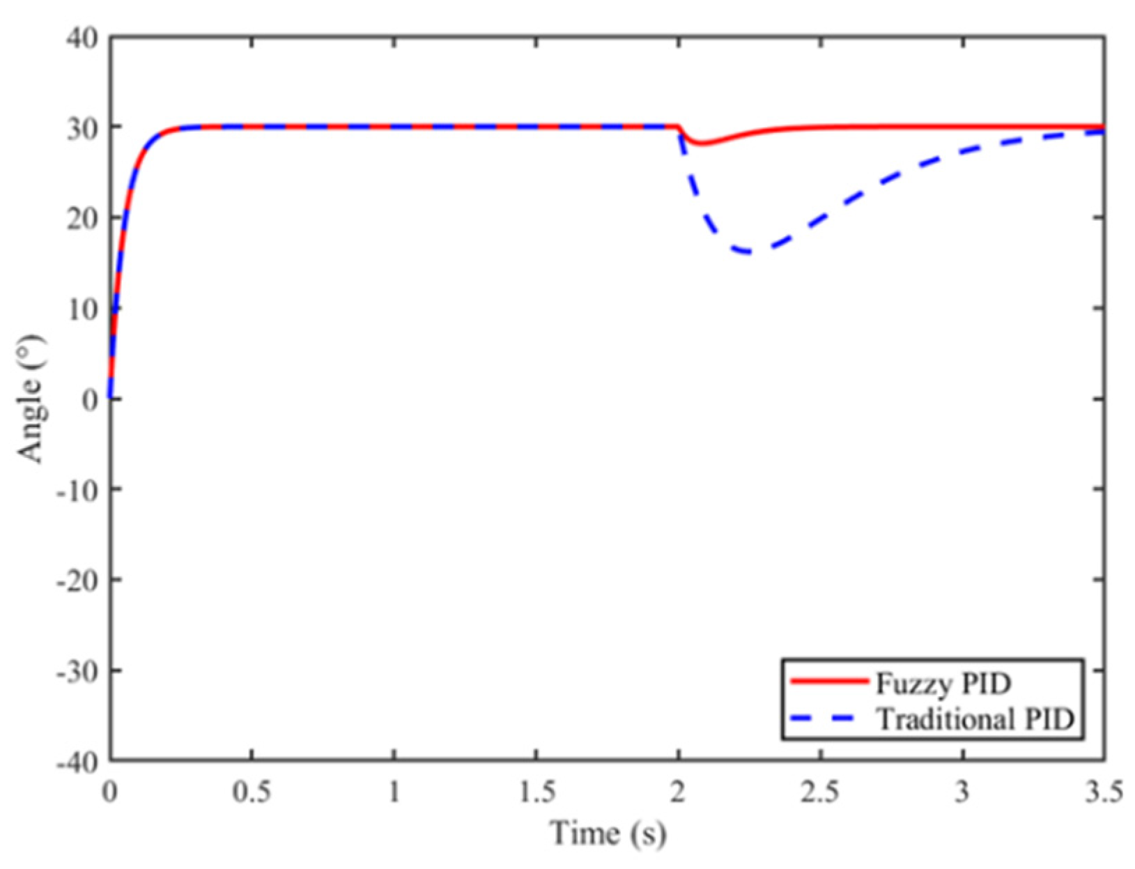
Figure 9.
Remote control flow of the intelligent hook.
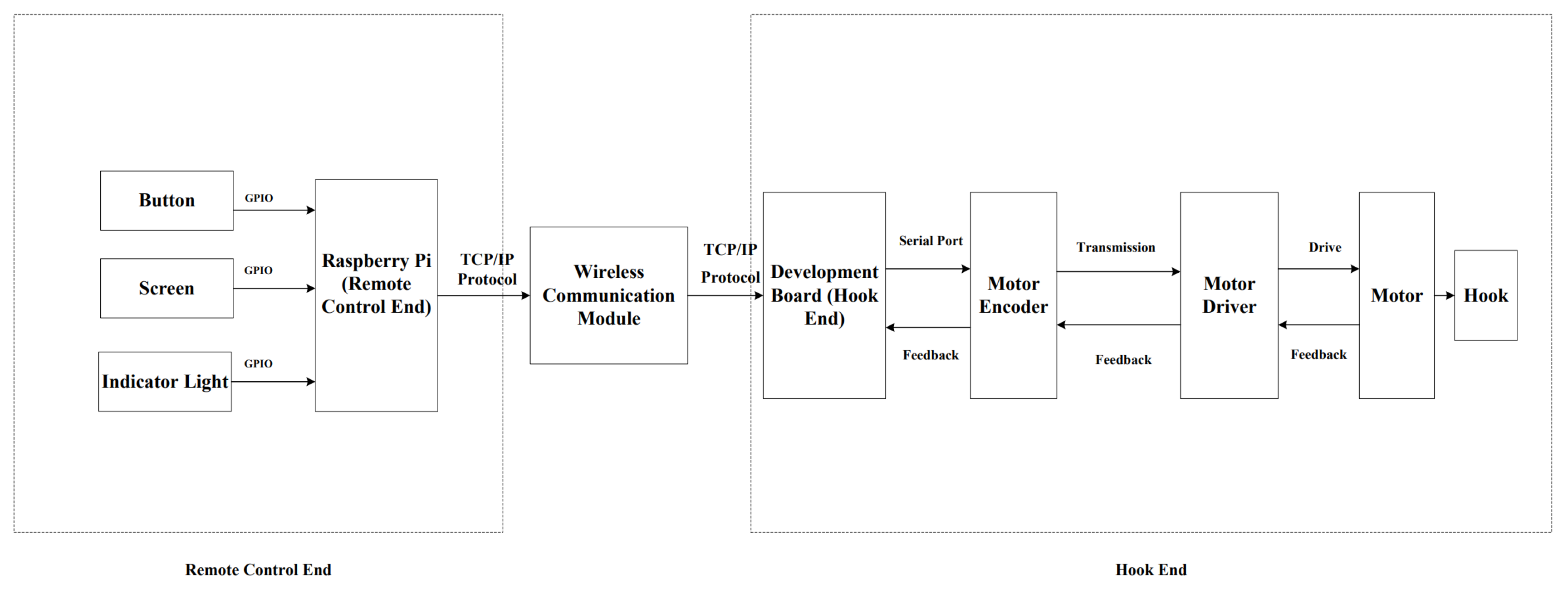
Figure 10.
Workflow diagram of the intelligent hook.
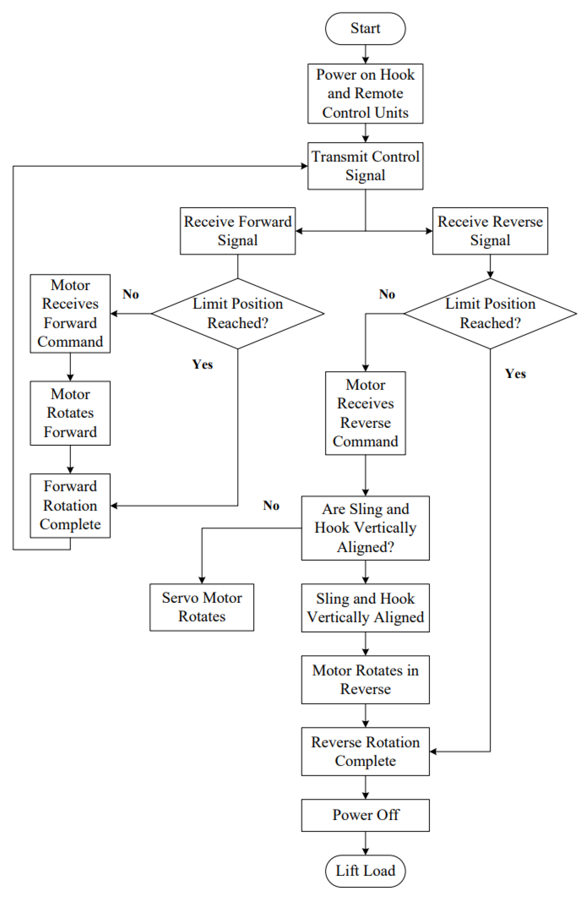
Figure 11.
Lifting (left) and descending (right) process of the intelligent hook.
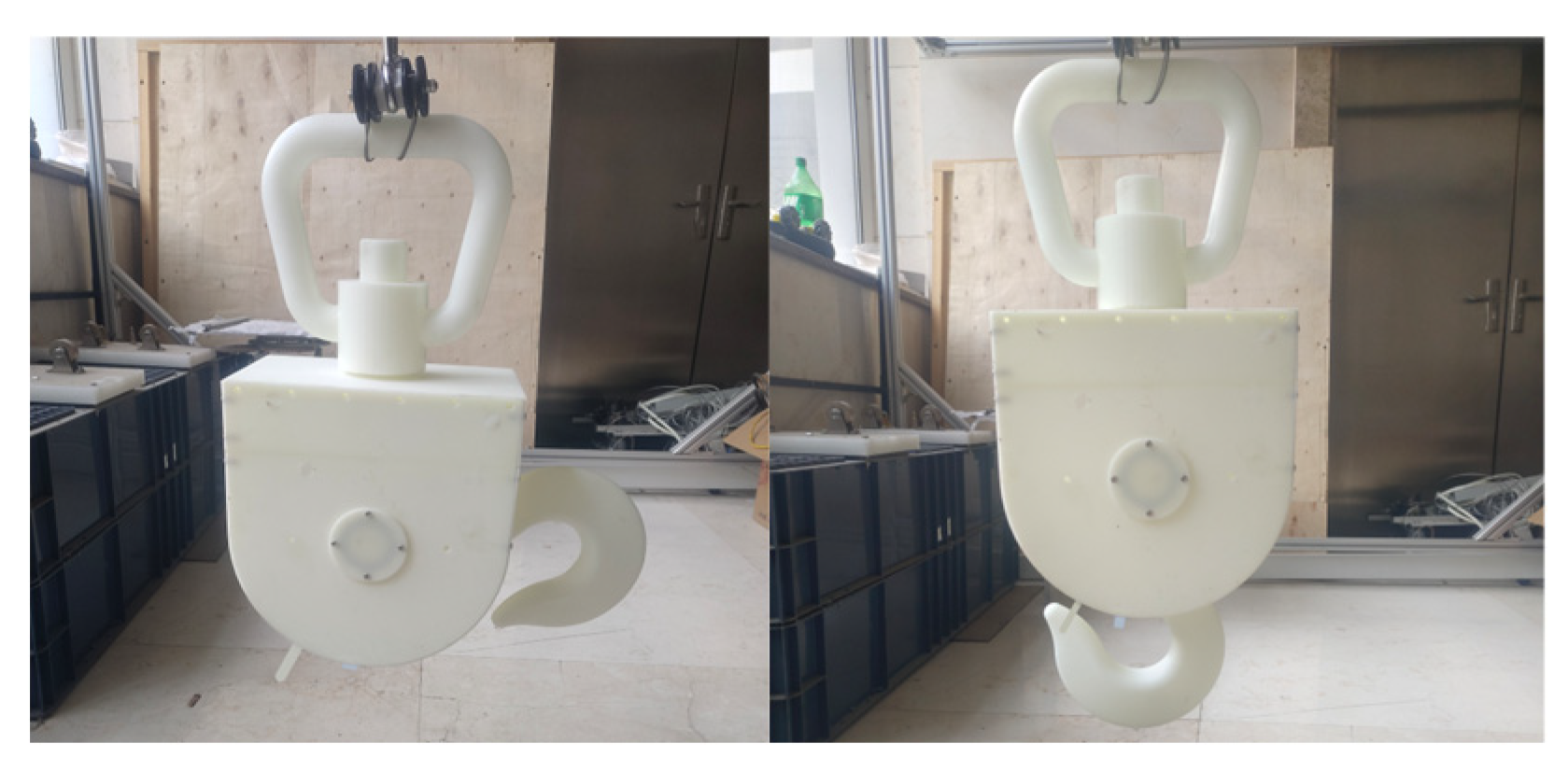
Figure 12.
Relative position of the sling and the hook.
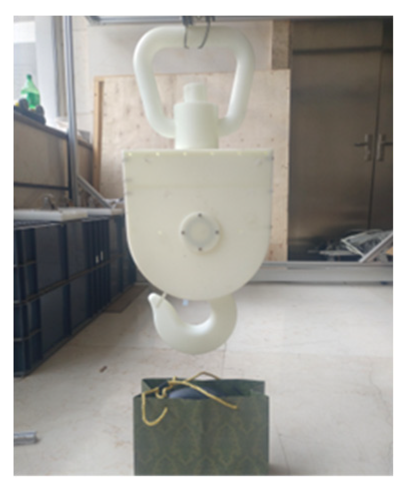
Figure 13.
Schematic diagram of the slewing motion of the intelligent hook.
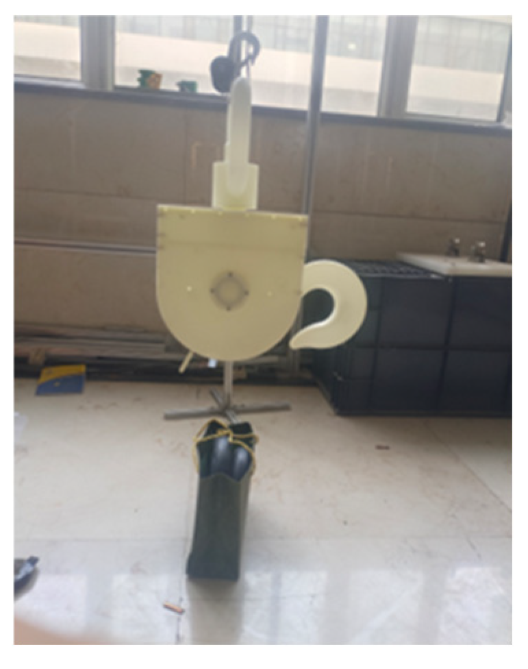
Figure 14.
The intelligent hook engaging the flexible sling.
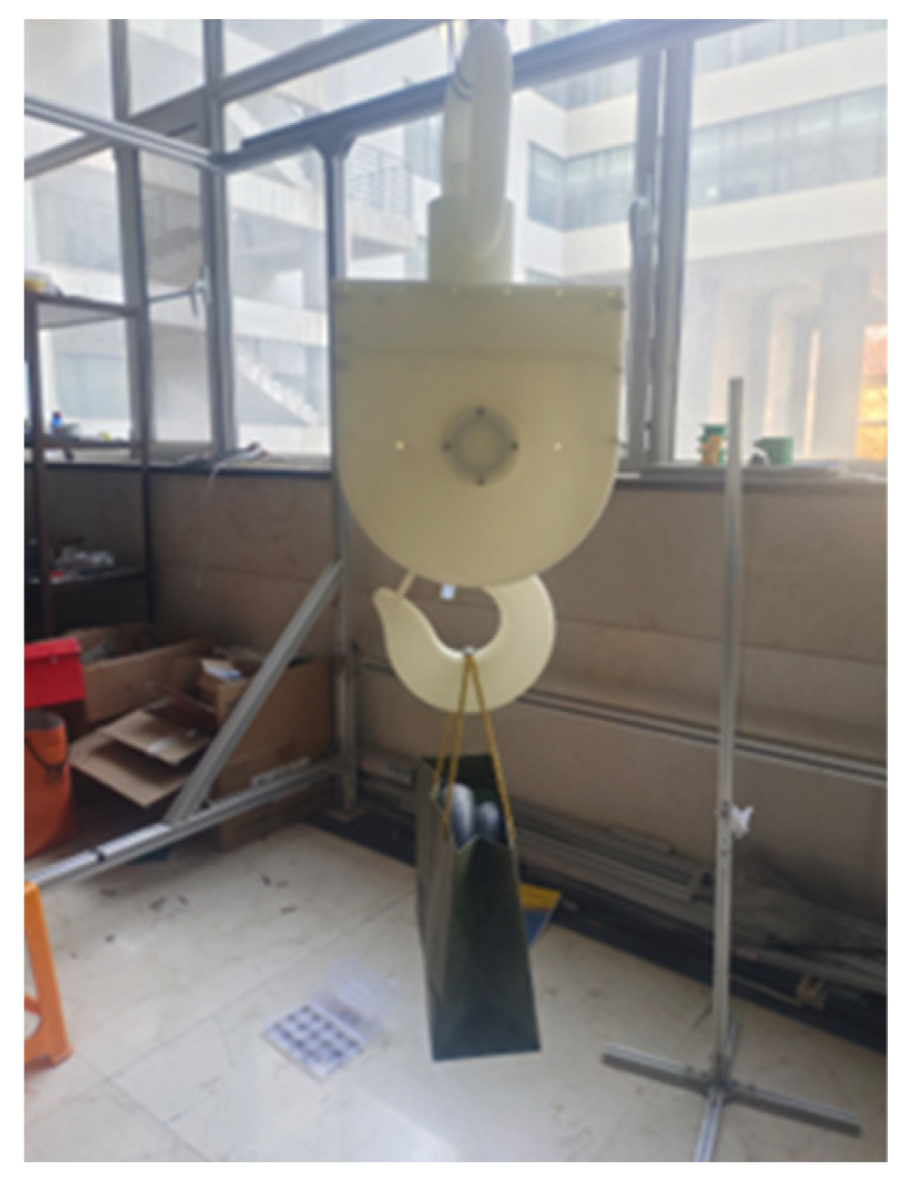
Figure 15.
Experimental curves of angle step response of the smart hook under different load conditions.
Figure 15.
Experimental curves of angle step response of the smart hook under different load conditions.
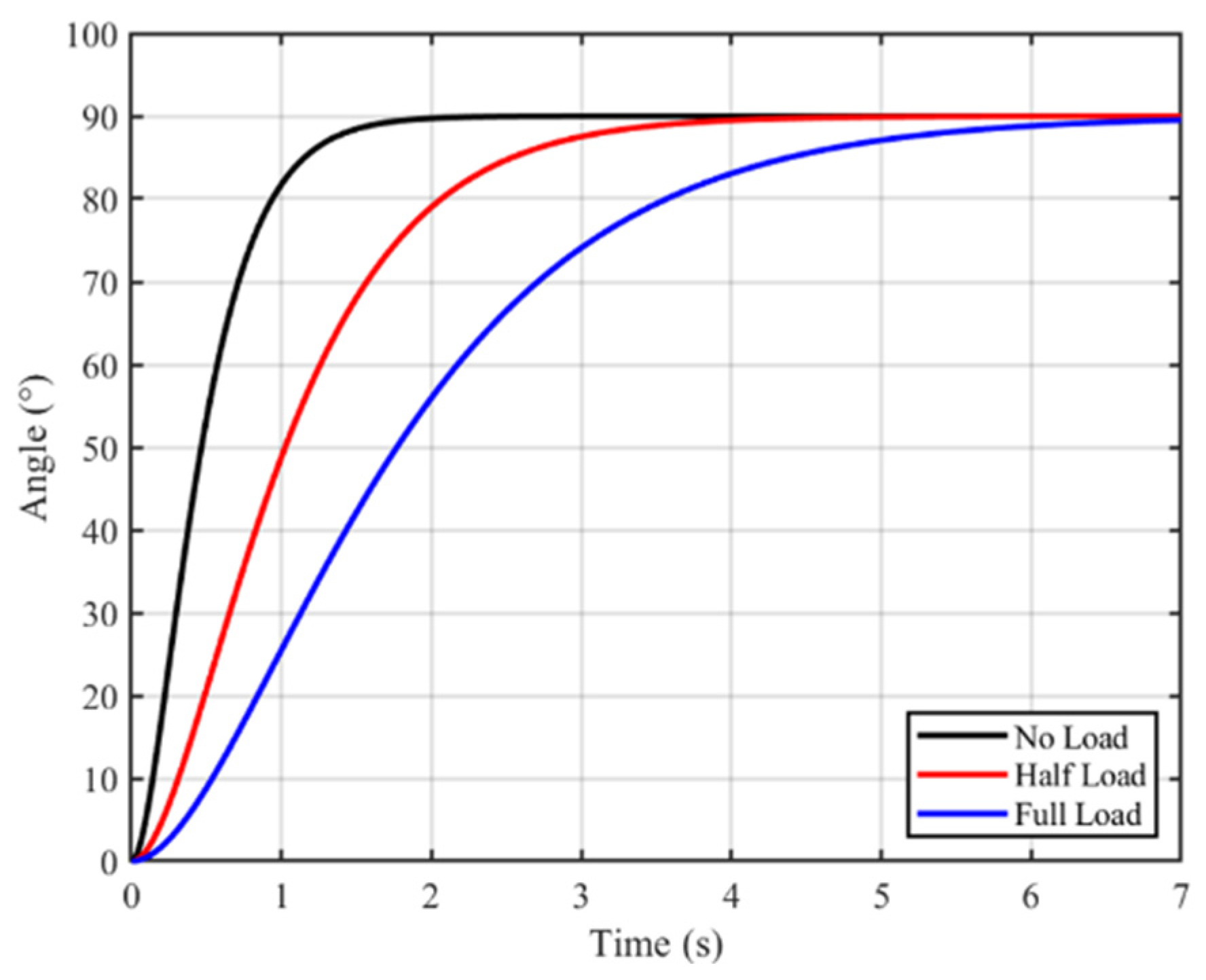
Figure 16.
System Architecture Diagram of the Intelligent Hook for Engineering Applications.
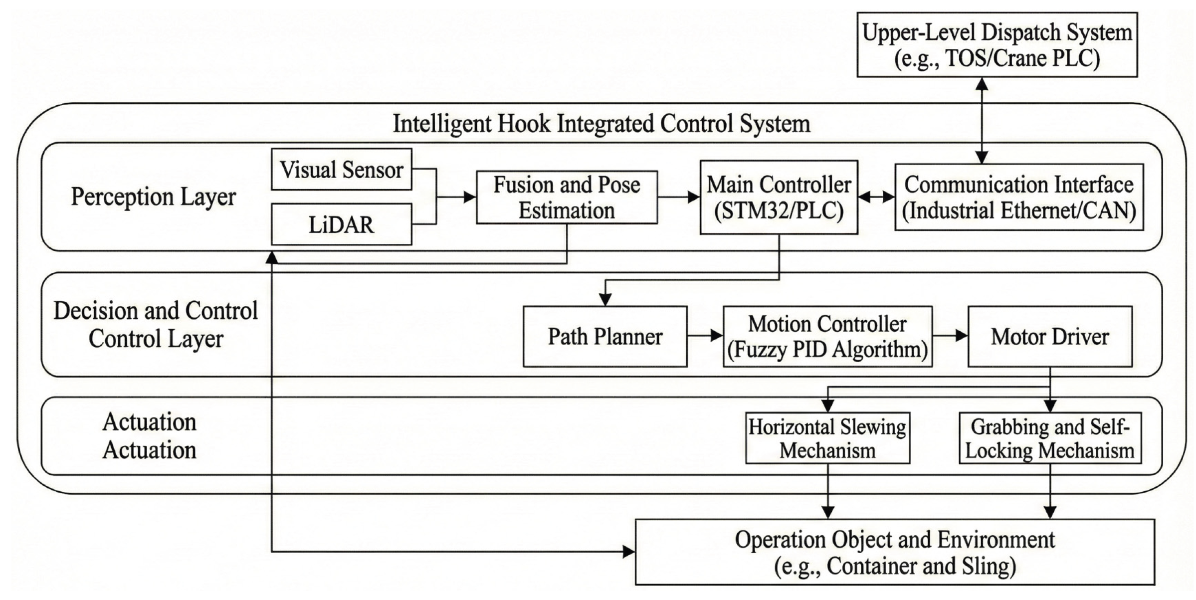

Table 2.
Mechanical characteristic parameters of Q345 steel.
| Slewing Shaft Material | Elastic Modulus/GPa | Yield Strength/MPa | Poisson's Ratio | Density/kg·mm-3 |
| Q345 | 202 | 345 | 0.31 | 7850 |
Table 3.
Performance comparison of different schemes.
| Angle | Scheme | Avg.Time(s) | Success Rate(%) |
| 0° | Intelligent Hook | 1.8 | 100 |
| Traditional Manual | 15.2 | 100 | |
| Non-slewing Hook | 2.1 | 100 | |
| 45° | Intelligent Hook | 2.5 | 95 |
| Traditional Manual | 18.5 | 90 | |
| Non-slewing Hook | Failure | 0 | |
| 90° | Intelligent Hook | 3.0 | 92 |
| Traditional Manual | 25+ | 70 | |
| Non-slewing Hook | Failure | 0 |
Disclaimer/Publisher’s Note: The statements, opinions and data contained in all publications are solely those of the individual author(s) and contributor(s) and not of MDPI and/or the editor(s). MDPI and/or the editor(s) disclaim responsibility for any injury to people or property resulting from any ideas, methods, instructions or products referred to in the content. |
© 2026 by the authors. Licensee MDPI, Basel, Switzerland. This article is an open access article distributed under the terms and conditions of the Creative Commons Attribution (CC BY) license (http://creativecommons.org/licenses/by/4.0/).
Copyright: This open access article is published under a Creative Commons CC BY 4.0 license, which permit the free download, distribution, and reuse, provided that the author and preprint are cited in any reuse.


