Submitted:
04 February 2026
Posted:
06 February 2026
You are already at the latest version
Abstract
In unmanned aerial vehicle (UAV) applications, the performance of simultaneous localization and mapping (SLAM) systems often degrades under high-frequency vibrations induced by airflow and wind disturbances, which can corrupt LiDAR measurements and lead to pose estimation drift or even complete system failure. To address this challenge, this paper proposes a graph optimizationbased multi-keyframe SLAM method designed to enhance robustness and accuracy under strong vibration conditions. Unlike conventional approaches that align the current frame only with the most recent keyframe, the proposed method aligns each LiDAR frame with multiple historical keyframes to construct a factor graph. Each alignment is modeled as a relative pose constraint between nodes, while an adaptive weighting strategy based on spatial distance and temporal interval dynamically balances the contributions of different keyframes. Global pose optimization is then performed within a non-linear least squares framework using the Gauss–Newton method. Experimental results on the NTU VIRAL dataset demonstrate that the proposed method significantly reduces both trajectory and rotational errors compared with LeGO-LOAM, achieving improvements of up to 71% and 84% in position and orientation accuracy, respectively. Furthermore, real-world UAV experiments validate the effectiveness and reliability of the proposed approach, showing stable and accurate mapping performance even under rapid aerial motion and external disturbances.
Keywords:
UAV
; LiDAR–inertial SLAM
; graph optimization
; multi-keyframe
; vibration robustness
; localization and mapping
1. Introduction
In recent years, unmanned aerial vehicles (UAVs) have been increasingly applied to tasks such as autonomous inspection, environmental monitoring, and logistics delivery. Reliable autonomous operation in these scenarios critically depends on accurate localization and mapping capabilities, especially in complex and dynamic environments. Among various perception techniques, LiDAR-based simultaneous localization and mapping (SLAM) has demonstrated notable advantages in terms of accuracy and robustness. Recent survey studies have systematically summarized the progress of LiDAR-based SLAM in robotics and autonomous systems, highlighting its effectiveness in large-scale, GPS-denied, and complex environments [1,2,3,4]. However, in real-world UAV operations, external disturbances such as airflow turbulence and wind gusts often induce high-frequency vibrations, which can severely corrupt LiDAR measurements and lead to unstable pose estimation or even complete SLAM failure.
To address motion-induced measurement degradation, a variety of LiDAR and LiDAR–inertial SLAM systems have been developed. Early LiDAR-only methods, such as LOAM [5], decompose the SLAM problem into high-frequency odometry estimation and low-frequency mapping optimization to achieve real-time performance. Building upon this framework, LeGO-LOAM [6] introduces ground-based constraints to improve computational efficiency on lightweight platforms. More recently, tightly coupled LiDAR–inertial SLAM approaches, including LIO-SAM [7], iEKF-based fusion methods [8], and multi-modal systems such as LVI-SAM [9], integrate inertial or visual information into optimization or filtering frameworks, significantly enhancing motion compensation and robustness under aggressive maneuvers. Comprehensive reviews on multi-sensor fusion SLAM further indicate that LiDAR–IMU–camera integration has become a dominant paradigm for improving robustness in highly dynamic scenarios [17,18,19,20].
Despite these advances, most existing LiDAR-based SLAM systems still rely primarily on sequential scan-to-scan or frame-to-keyframe alignment strategies. Under high-frequency vibration and rapid attitude changes, such local registration schemes are prone to accumulating drift over time, as corrupted measurements cannot be effectively corrected using limited temporal context. Moreover, aligning the current frame with only the most recent keyframe restricts the utilization of historical spatial information, reducing the system’s ability to achieve globally consistent pose estimation in challenging flight conditions. Similar limitations have been identified in recent comparative evaluations and large-scale LiDAR SLAM analyses [21,22,23].
Graph-based optimization has become a fundamental paradigm in modern SLAM, formulating state estimation as a nonlinear least-squares problem on a factor graph. Efficient solvers such as g2o [12], Ceres Solver [11], and incremental methods like iSAM2 [15] enable large-scale and real-time optimization, and have been successfully applied in practical systems including Google Cartographer [14] and ORB-SLAM [10]. Survey studies on SLAM architectures further emphasize that factor graph optimization provides a principled way to incorporate heterogeneous constraints and long-term temporal information [24]. However, in many existing implementations, graph optimization is still constructed upon locally constrained measurements, limiting its effectiveness when facing severe vibration-induced noise and rapid UAV motion. To overcome these limitations, this paper proposes a multi-keyframe graph optimization-based SLAM method specifically tailored for UAV operations under high-vibration conditions. Instead of relying on a single reference keyframe, the proposed approach aligns each incoming LiDAR frame with multiple historical keyframes and formulates the resulting constraints as a factor graph for joint pose optimization. An adaptive weighting strategy that jointly considers spatial distance and temporal interval is further introduced to balance the contributions of different keyframes. The resulting nonlinear least-squares problem is efficiently solved using the Gauss–Newton method, leading to more stable and globally consistent pose estimation under challenging flight conditions.
Comprehensive experiments are conducted on the NTU VIRAL dataset [25] as well as on a real UAV platform. The results demonstrate that the proposed method significantly improves localization accuracy and mapping consistency compared with LeGO-LOAM, particularly in scenarios involving severe UAV vibrations and rapid motion.
2. Materials and Methods
2.1. System Framework
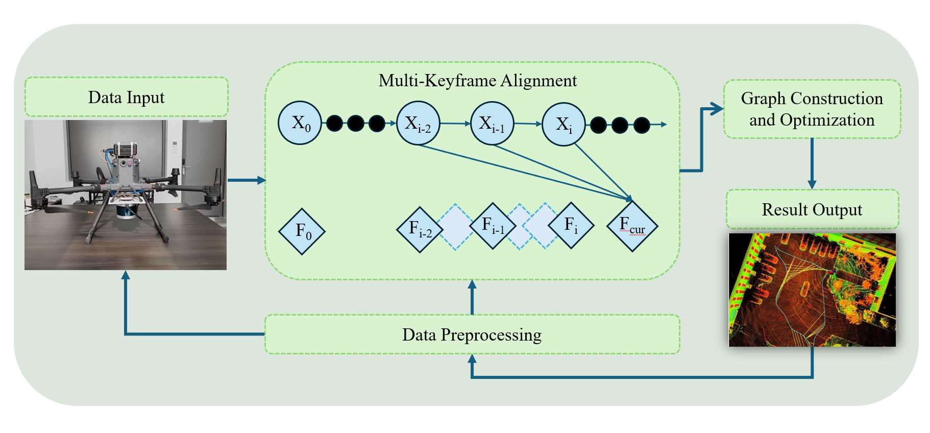
The proposed keyframe-based graph optimization method is designed to enhance the robustness and accuracy of LiDAR SLAM for UAVs operating under vibration disturbances. As illustrated in Figure 1, the overall system framework consists of four main modules: data preprocessing, multi-keyframe alignment, graph construction and optimization, and result output.
In the data preprocessing module, raw LiDAR measurements are first temporally synchronized and compensated for motion distortion caused by UAV movement. Subsequently, feature extraction is performed to identify edge and planar feature points, which serve as inputs for the subsequent point cloud registration process.
The multi-keyframe alignment module aligns the current LiDAR frame not only with the most recent keyframe, but also with multiple historical keyframes within a certain temporal window. For each selected keyframe, a relative transformation between the current frame and the keyframe is estimated through point cloud registration. By leveraging multiple keyframes, this module generates several local pose constraints, which provide richer and more redundant information for robust pose estimation.
In the graph construction and optimization module, the relative pose constraints obtained from multi-keyframe alignment are integrated into a unified factor graph. In this graph, nodes represent the poses of the current frame and selected keyframes, while edges encode the relative transformations between them. The overall pose estimation problem is formulated as a nonlinear least-squares optimization, which is solved using a Gauss–Newton-based approach to jointly optimize all involved poses. This global optimization process effectively mitigates noise accumulation and drift induced by high-frequency UAV vibrations, leading to improved pose consistency.
Finally, in the result output module, the optimized pose of the current frame is extracted and incorporated into the global map. The updated map and pose estimates are then provided as outputs for downstream UAV navigation and mapping tasks. All system modules are implemented in a modular and extensible manner, facilitating reproducibility and independent evaluation.
2.2. Factor Graph Construction
In keyframe-based factor graph optimization, the construction of reliable constraints plays a crucial role in achieving stable and accurate pose estimation. By aligning the current LiDAR frame with multiple historical keyframes and exploiting the existing inter-keyframe relationships, a factor graph composed of multiple vertices and edges is constructed. In this representation, each vertex corresponds to a pose variable to be optimized, while each edge encodes a spatial constraint derived from point cloud registration residuals.
In a SLAM framework, relative pose constraints between keyframes are commonly obtained through pairwise point cloud alignment. Let and denote two keyframes associated with point clouds and , respectively. The relative transformation between them can be estimated by minimizing the point-to-point registration error:
Here, and represent the k-th corresponding points in the point clouds of keyframes and . This formulation applies not only to relative pose estimation between consecutive historical keyframes, such as , but also to the alignment between the current frame and multiple preceding keyframes. The resulting set of relative transformations constitutes the edge constraints of the factor graph.
By incorporating multiple spatial and temporal constraints from both recent and earlier keyframes, the proposed method improves the connectivity and redundancy of the factor graph, thereby enhancing the robustness of pose estimation under noisy measurements and dynamic UAV motion.
In conventional multi-keyframe alignment strategies, all historical keyframes are typically treated with equal importance when estimating the pose of the current frame. However, in real-world UAV operations, the influence of each keyframe varies depending on its spatial proximity and temporal relevance. To address this issue, a dual-factor adaptive weighting strategy is introduced, which assigns different weights to each keyframe based on both spatial distance and temporal interval.
The distance weight between the current frame and a historical keyframe is defined as:
where denotes the Euclidean distance between the poses of and , and is a tunable parameter controlling the decay rate of the distance weight.
Similarly, the temporal weight is defined as:
where represents the time interval between and , and and denote the maximum and minimum time intervals among all selected keyframes, respectively.
The combined weight for each keyframe is computed as:
where is a fusion coefficient that balances the contributions of spatial and temporal factors.
Using these adaptive weights, the relative transformation between the current frame and each historical keyframe is estimated as:
In addition, relative transformations between adjacent historical keyframes are refined using corresponding inter-keyframe weights:
where is computed based on the spatial and temporal relationships between the two keyframes. These weighted constraints are directly incorporated into the factor graph optimization process in both dataset-based evaluations and real UAV experiments, as described in Results Section.
2.3. Factor Graph Structure
Based on the constraints described in the previous subsection, a local factor graph is constructed to jointly optimize the poses of the current LiDAR frame and multiple historical keyframes. In this graph, each node represents a 6-DoF pose of a keyframe or the current frame, while each edge encodes a relative transformation constraint obtained from weighted point cloud registration, as illustrated in Figure 1. The factor graph is maintained in a sliding-window manner, allowing the system to balance computational efficiency and robustness.
Specifically, the constructed factor graph contains the following types of edges:
- An edge between and , representing the relative transformation ;
- An edge between and , representing the relative transformation ;
- An edge between the current frame and the historical keyframe , representing ;
- An edge between and , representing ;
- An edge between and , representing .
By connecting the current frame with multiple recent keyframes, the proposed graph structure introduces redundant spatial–temporal constraints that are particularly beneficial under high-frequency vibration and rapid motion. At the same time, limiting the graph to a small set of temporally adjacent keyframes avoids excessive computational overhead and reduces the risk of incorporating outdated or inconsistent constraints. All edges in the factor graph are weighted according to the adaptive spatial–temporal strategy described in the previous subsection, ensuring that more relevant keyframes contribute more significantly to the overall optimization.
This factor graph structure enables robust and locally consistent pose estimation by effectively leveraging both short-term motion continuity and longer-term spatial consistency, thereby mitigating vibration-induced noise and pose drift in UAV LiDAR SLAM.
2.4. Graph Optimization
In the proposed multi-keyframe SLAM framework, graph optimization aims to jointly minimize the residuals of all weighted edges in a local sliding window of the factor graph. Let the graph contain n edges and m nodes within the current optimization window. The objective function is defined as:
where
- denotes the set of node poses within the sliding window, with representing the state of the i-th node;
- is the error function for the k-th edge, which may involve the current frame and one or more historical keyframes;
- is the information matrix that incorporates the adaptive spatial-temporal weights described in Factor Graph Structure Subsection, ensuring that edges corresponding to more relevant keyframes have higher influence.
Specifically, the edge residuals are defined on as follows:
As in standard pose graph optimization, the factor graph is sparse: each node is connected only to a subset of edges in the sliding window. This sparsity allows efficient computation by reducing the number of non-zero elements in the Hessian matrix.
To solve the nonlinear least-squares problem, the Gauss–Newton method is employed iteratively within the sliding window. The main steps are:
- 1.
- Jacobian computation: calculate partial derivatives of each edge residual with respect to the connected node poses, forming the Jacobian ;
- 2.
- Linearization: approximate each residual using first-order Taylor expansion around the current estimate :
- 3.
- Linear system formation: accumulate the contributions from all edges in the sliding window to form
- 4.
- State update: solve for and update all node poses within the sliding window:
- 5.
- Convergence check: evaluate residual reduction and iterate until convergence criteria are met.
By performing Gauss–Newton optimization on this weighted multi-keyframe factor graph, the system achieves robust and globally consistent pose estimation, effectively mitigating the impact of UAV vibrations and high-frequency measurement noise while maintaining computational efficiency.
3. Results
3.1. Experimental Evaluation on Datasets
To evaluate the performance of the proposed optimization method, experiments were conducted on the NTU VIRAL dataset. The NTU VIRAL dataset, developed by the research team at Nanyang Technological University in Singapore, is designed to meet the complex requirements of autonomous aerial vehicles. It integrates a variety of sensor configurations, including two 3D LiDAR units, stereo time-synchronized cameras, multiple inertial measurement units (IMUs), and four sets of ultra-wideband nodes, forming a comprehensive perception system. These sensors work collaboratively to capture environmental information from diverse perspectives, providing high-quality multimodal data for algorithm evaluation. Flight tests were conducted in various indoor and outdoor environments, covering scenarios from urban streets to complex indoor spaces, making the dataset a comprehensive benchmark for UAV SLAM performance assessment.
To quantitatively assess the performance of the proposed method, we compared it with the widely-used LeGO-LOAM algorithm, as it represents a strong baseline for LiDAR-only SLAM under vibration-prone conditions. LeGO-LOAM has demonstrated strong performance in LiDAR-based SLAM, particularly in point cloud processing and map construction. For a reliable evaluation benchmark, ground-truth trajectories were generated using an IMU-assisted SLAM system. The IMU provides real-time pose and acceleration data, which, when fused with LiDAR measurements, yields trajectories that closely approximate the true motion of the UAV, enabling a more objective and accurate comparison between algorithms.
Figure 4 further compares the trajectory and rotational estimation results obtained using the proposed method and LeGO-LOAM. During the experiments, UAVs were subject to external disturbances, such as vibration, posing a significant challenge for pose estimation. LeGO-LOAM exhibits noticeable deviations under such conditions, resulting in less accurate environmental reconstruction. The reconstructed maps closely match the real environment, clearly preserving key structural and geometric features. This indicates that the proposed approach is highly resilient to UAV-induced perturbations, ensuring precise localization and reliable mapping in challenging scenarios.
Figure 2.
Comparison of mapping results in outdoor environments.
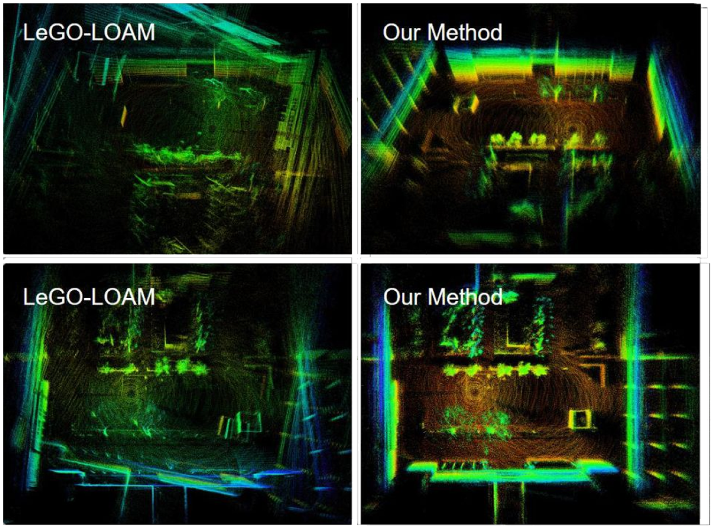
Figure 3.
Comparison of mapping results in indoor environments.
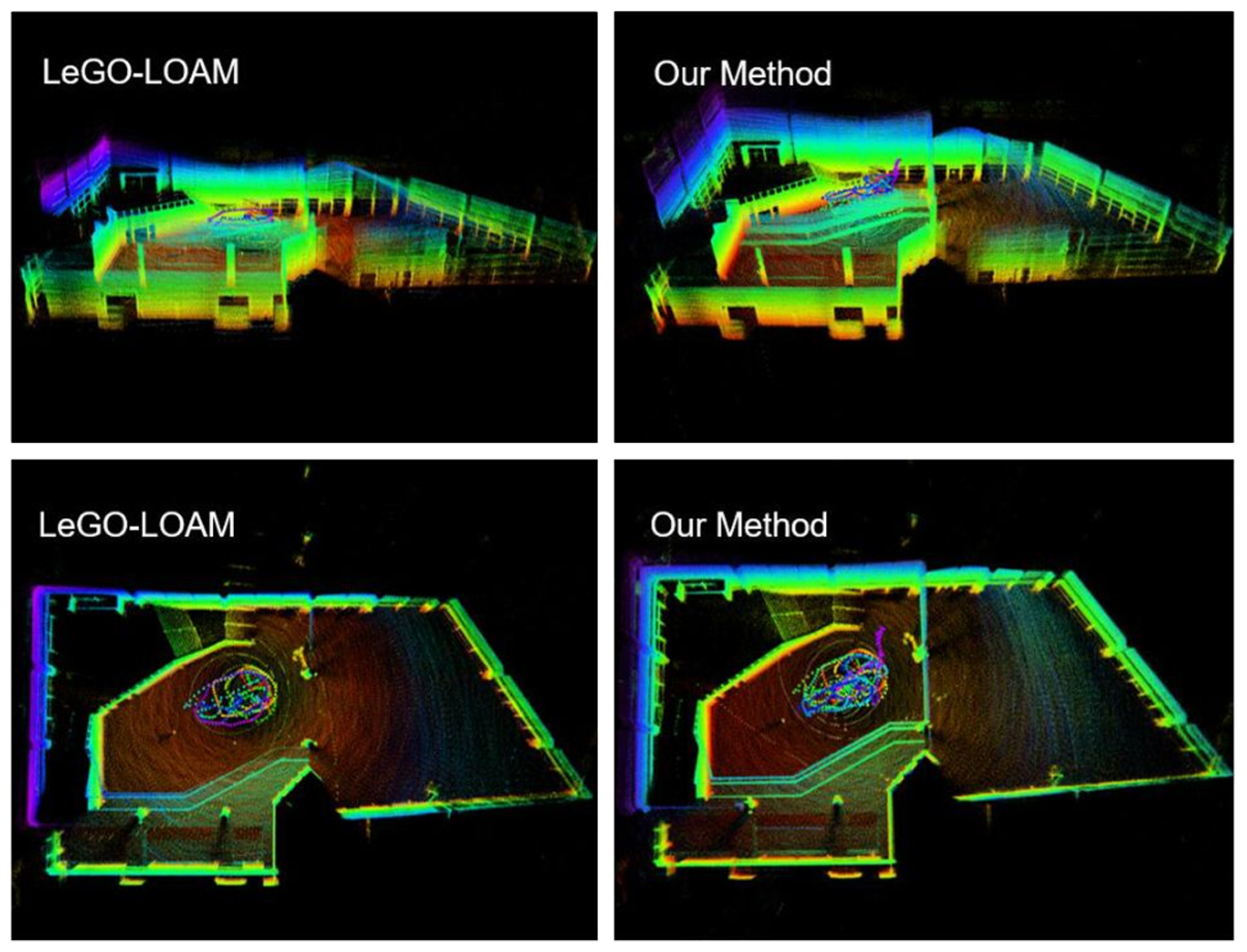
Figure 4.
Comparison of trajectory and rotational estimation between the proposed method and LeGO-LOAM. Subfigures (a)–(d) respectively show indoor translation, indoor rotation, outdoor translation, and outdoor rotation results.
Figure 4.
Comparison of trajectory and rotational estimation between the proposed method and LeGO-LOAM. Subfigures (a)–(d) respectively show indoor translation, indoor rotation, outdoor translation, and outdoor rotation results.
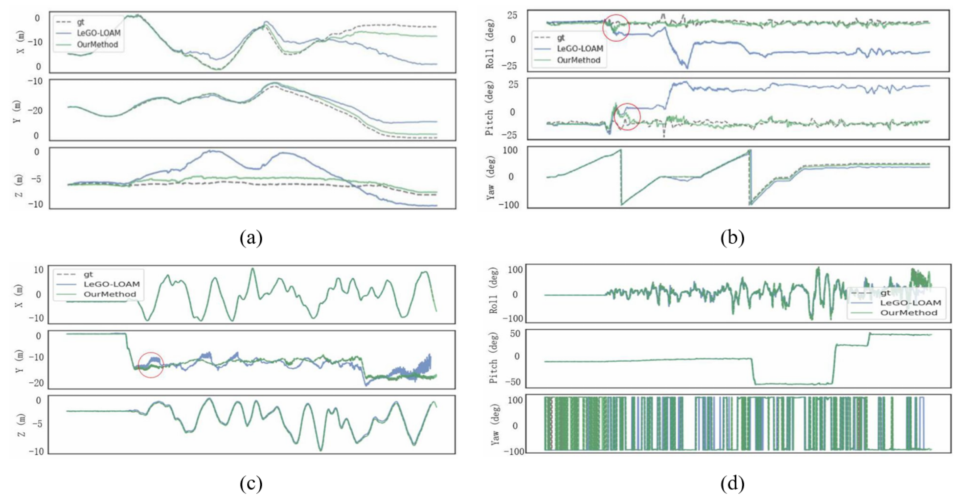
In addition to these qualitative mapping results, we further evaluate the trajectory and rotational accuracy quantitatively using ground-truth data. Table 1 and Table 2 provide quantitative comparisons of trajectory and rotational errors. In outdoor scenarios, the trajectory RMSE for LeGO-LOAM reaches 8.00 m, whereas the proposed method reduces it to 2.32 m, corresponding to an improvement of approximately 71%. The rotational RMSE is reduced from 45.01° to 7.06° (∼84% improvement), reflecting the effectiveness of multi-keyframe constraints and spatial-temporal weighting in suppressing vibration-induced orientation errors. In indoor environments, trajectory RMSE is reduced from 0.49 m to 0.35 m (∼29% improvement), while rotational RMSE decreases from 2.98° to 1.71° (∼43% improvement).
These results demonstrate that the proposed method significantly outperforms LeGO-LOAM in both localization accuracy and rotational consistency. The multi-keyframe graph optimization with spatial-temporal weighting effectively reduces drift and suppresses vibration-induced noise, ensuring reliable and precise mapping performance in real-world UAV applications.
3.2. Algorithm Deployment
To comprehensively validate the performance of the proposed graph-based multi-keyframe joint optimization method in real-world scenarios, we deployed the proposed algorithm on an unmanned aerial vehicle (UAV) platform and performed field experiments to evaluate its practical effectiveness. This section presents the hardware configuration, data collection process, and experimental results.
As shown in Figure 5, the UAV platform mainly consists of the following components:
- 1.
- Velodyne VLP-16 LiDAR: Serves as the primary environmental perception sensor.
- 2.
- IMU: Provides high-frequency attitude and acceleration data to assist LiDAR data compensation.
- 3.
- NUC Mini Computer: Executes the proposed SLAM algorithm in real time. Its compact design and low power consumption make it ideal for UAV applications.
- 4.
- UAV Platform: Provides stable flight control and payload capability to carry the LiDAR, IMU, and NUC.
Figure 6 presents the 3D map reconstructed by the proposed algorithm. Key structural and geometric features, including building contours, road layouts, and vegetation distributions, are accurately preserved, demonstrating the algorithm’s ability to capture both large-scale structures and fine details. The point cloud exhibits high density and uniform distribution, demonstrating the algorithm’s accuracy and robustness in environmental perception and map construction.
Figure 7 shows the experimental UAV platform. The UAV performed flights over diverse environments, including open spaces, building surroundings, and vegetation-rich areas, enabling comprehensive evaluation of the algorithm’s robustness.
Table 3 presents quantitative errors in trajectory and rotation. The low RMSE, mean, and standard deviation values indicate that the proposed algorithm preserves accurate pose estimates under real-world UAV conditions, consistent with the dataset-based evaluation. Table 3 and Fig. Figure 8 illustrate that the estimated UAV trajectory closely aligns with the ground truth, exhibiting minimal deviation even in complex environments. These results confirm that the proposed algorithm maintains high localization accuracy and stable tracking performance, ensuring reliable UAV localization and supporting autonomous navigation. The overall mapping and trajectory validation confirm the strong real-world applicability of the proposed SLAM system.
4. Discussion
The experimental results demonstrate that the proposed multi-keyframe graph optimization approach substantially improves localization accuracy and mapping consistency under high-vibration UAV conditions. Compared with LeGO-LOAM, the method achieves reduced trajectory drift and enhanced robustness, particularly during rapid attitude changes. For instance, the outdoor trajectory RMSE decreased from 8.00 m to 2.32 m, while rotational RMSE dropped from 45.01° to 7.06°, highlighting the effectiveness of the approach in challenging scenarios.
The performance improvement primarily arises from joint optimization over multiple historical keyframes. By incorporating spatially and temporally distributed constraints into the factor graph, the method effectively mitigates the adverse effects of vibration-induced LiDAR measurement noise. In contrast, traditional scan-to-scan or single-keyframe-based approaches tend to accumulate errors when local alignment becomes unreliable.
The proposed adaptive weighting strategy further enhances system stability by dynamically balancing the contributions of different keyframes. Keyframes that are spatially closer and temporally more relevant exert stronger influence during optimization, which helps maintain local consistency while preserving the global map structure. This combination of multi-keyframe constraints and adaptive weighting ensures accurate pose estimation and consistent map reconstruction even under rapid UAV maneuvers and external disturbances.
Despite these advantages, certain limitations remain. Increasing the number of keyframes involved in optimization inevitably raises computational cost compared with lightweight SLAM frameworks. Although real-time performance is demonstrated on the onboard NUC computer, further optimization or hardware acceleration may be required for smaller UAV platforms with stricter payload constraints.
Overall, these findings indicate that the proposed approach provides a favorable trade-off between accuracy and computational complexity, making it well-suited for practical UAV applications in dynamic and vibration-prone environments.
5. Conclusions
This paper addressed the limited accuracy and stability of UAV-based SLAM systems under severe motion disturbances. The proposed method exploits spatial-temporal correlations in historical observations by aligning the current frame with multiple historical keyframes and constructing a pose graph, thereby substantially improving pose estimation accuracy and robustness.
Extensive experiments on the NTU VIRAL dataset demonstrated that the proposed method outperforms LeGO-LOAM, reducing trajectory RMSE by up to 71% and rotational RMSE by up to 84%, particularly under rapid motion and oscillatory disturbances. Real-world UAV experiments further confirmed the practical applicability of the method, demonstrating real-time processing and accurate mapping in complex environments, including buildings, vegetation, and ground structures.
Overall, the graph-based multi-keyframe optimization framework effectively mitigates UAV vibration effects, enhances localization accuracy and mapping consistency, and exhibits strong potential for deployment in practical aerial applications.
Author Contributions
Conceptualization, Y.T. and J.S.; Methodology, Y.T.; Software, Y.T. and H.Y.; Validation, Y.T. and Y.W.; Formal analysis, Y.T. and H.Y.; Investigation, Y.T.; Resources, Y.W. and J.S.; Data curation, Y.T.; Writing—original draft preparation, Y.T.; Writing—review and editing, Y.T., Y.W., H.Y. and J.S.; Visualization, Y.T.; Supervision, J.S.; Project administration, J.S.; Funding acquisition, J.S. All authors have read and agreed to the published version of the manuscript.
Funding
This research received no external funding.
Institutional Review Board Statement
Not applicable.
Informed Consent Statement
Not applicable.
Data Availability Statement
The data presented in this study are available on request from the corresponding author.
Acknowledgments
The authors would like to acknowledge the support of computational resources and experimental facilities provided by Xi’an Jiaotong University. The authors also thank Prof. Jian Sun for guidance and supervision.
Conflicts of Interest
The authors declare no conflicts of interest. The funders had no role in the design of the study; in the collection, analyses, or interpretation of data; in the writing of the manuscript; or in the decision to publish the results.
References
- Zhang, Y.; Shi, P.; Li, J. 3D LiDAR SLAM: A Survey. Photogramm. Rec. 2024, 39, 457–517. [Google Scholar] [CrossRef]
- Jiang, H.; Cheng, Y.; Dai, W.; et al. GPS-Denied LiDAR-Based SLAM—A Survey. IET Cyber-Syst. Robot. 2025, 7, e70031. [Google Scholar] [CrossRef]
- Li, Y.; An, J.; He, N.; et al. A Review of Simultaneous Localization and Mapping Algorithms Based on LiDAR. World Electr. Veh. J. 2025, 16, 56. [Google Scholar] [CrossRef]
- Yue, X.; Zhang, Y.; Chen, J.; et al. LiDAR-Based SLAM for Robotic Mapping: State of the Art and New Frontiers. Ind. Robot 2024, 51, 196–205. [Google Scholar] [CrossRef]
- Zhang, J.; Singh, S. LOAM: Lidar Odometry and Mapping in Real-Time. In Proceedings of the Robotics: Science and Systems, Berkeley, CA, USA, 12–16 July 2014; pp. 1–9. [Google Scholar]
- Shan, T.; Englot, B. LeGO-LOAM: Lightweight and Ground-Optimized Lidar Odometry and Mapping on Variable Terrain. In Proceedings of the IEEE/RSJ International Conference on Intelligent Robots and Systems (IROS), Madrid, Spain, 1–5 October 2018; pp. 4758–4765. [Google Scholar]
- Shan, T.; Englot, B.; Meyers, D.; Wang, W.; Ratti, C.; Rus, D. LIO-SAM: Tightly-Coupled Lidar Inertial Odometry via Smoothing and Mapping. In Proceedings of the IEEE/RSJ International Conference on Intelligent Robots and Systems (IROS), Las Vegas, NV, USA, 25–29 October 2020; pp. 5135–5142. [Google Scholar]
- Xu, W.; Zhang, F. Fast-LIO: A Fast, Robust Lidar-Inertial Odometry Package by Tightly-Coupled Iterated Kalman Filter. IEEE Robot. Autom. Lett. 2021, 6, 3317–3324. [Google Scholar] [CrossRef]
- Shan, T.; Englot, B.; Ratti, C.; Rus, D. LVI-SAM: Tightly-Coupled Lidar-Visual-Inertial Odometry via Smoothing and Mapping. In Proceedings of the IEEE International Conference on Robotics and Automation (ICRA), Xi’an, China, 30 May–5 June 2021; pp. 5692–5698. [Google Scholar]
- Mur-Artal, R.; Montiel, J.M.M.; Tardós, J.D. ORB-SLAM: A Versatile and Accurate Monocular SLAM System. IEEE Trans. Robot. 2015, 31, 1147–1163. [Google Scholar] [CrossRef]
- Agarwal, S.; Mierle, K. Ceres Solver: Tutorial and Reference. Google Inc. 2012, 2, 1–72. [Google Scholar]
- Kümmerle, R.; Grisetti, G.; Strasdat, H.; Konolige, K.; Burgard, W. g2o: A General Framework for Graph Optimization. In Proceedings of the IEEE International Conference on Robotics and Automation, Shanghai, China, 9–13 May 2011; pp. 3607–3613. [Google Scholar]
- Yi, S.; Lyu, Y.; Hua, L.; Pan, Q.; Zhao, C. Light-LOAM: A Lightweight LiDAR Odometry and Mapping Based on Graph-Matching. IEEE Robot. Autom. Lett. 2024, 9, 3219–3226. [Google Scholar] [CrossRef]
- Dwijotomo, A.; Rahman, M.A.A.; Ariff, M.H.M.; Zamzuri, H.; Azree, W.M.H. Cartographer SLAM Method for Optimization with an Adaptive Multi-Distance Scan Scheduler. Appl. Sci. 2020, 10, 347. [Google Scholar] [CrossRef]
- Kaess, M.; Johannsson, H.; Roberts, R.; Ila, V.; Leonard, J.; Dellaert, F. iSAM2: Incremental Smoothing and Mapping with Fluid Relinearization and Incremental Variable Reordering. In Proceedings of the IEEE International Conference on Robotics and Automation, Shanghai, China, 9–13 May 2011; pp. 3281–3288. [Google Scholar]
- Wang, Y.; Sun, J.; Zhou, F. Three-Stage Hierarchical LiDAR SLAM with Confidence-Based Pose Selection for Enhanced Vertical Accuracy. In Proceedings of the International Conference on Mechanical Engineering and Robotics Research (ICMERR), 2025; pp. 94–100. [Google Scholar]
- Zhu, J.; Li, H.; Zhang, T. Camera, LiDAR, and IMU Based Multi-Sensor Fusion SLAM: A Survey. Tsinghua Sci. Technol. 2023, 29, 415–429. [Google Scholar] [CrossRef]
- Xu, X.; Zhang, L.; Yang, J.; et al. A Review of Multi-Sensor Fusion SLAM Systems Based on 3D LiDAR. Remote Sens. 2022, 14, 2835. [Google Scholar] [CrossRef]
- Fan, Z.; Zhang, L.; Wang, X.; et al. LiDAR, IMU, and Camera Fusion for Simultaneous Localization and Mapping: A Systematic Review. Artif. Intell. Rev. 2025, 58, 1–59. [Google Scholar] [CrossRef]
- Debeunne, C.; Vivet, D. A Review of Visual–LiDAR Fusion Based Simultaneous Localization and Mapping. Sensors 2020, 20, 2068. [Google Scholar] [CrossRef] [PubMed]
- Ćwian, K.; Nowicki, M.R.; Wietrzykowski, J.; et al. Large-Scale LiDAR SLAM with Factor Graph Optimization on High-Level Geometric Features. Sensors 2021, 21, 3445. [Google Scholar] [CrossRef] [PubMed]
- Lee, D.; Jung, M.; Yang, W.; et al. LiDAR Odometry Survey: Recent Advancements and Remaining Challenges. Intell. Serv. Robot. 2024, 17, 95–118. [Google Scholar] [CrossRef]
- Garigipati, B.; Strokina, N.; Ghabcheloo, R. Evaluation and Comparison of Eight Popular LiDAR and Visual SLAM Algorithms. In Proceedings of the 25th International Conference on Information Fusion (FUSION), Linköping, Sweden, 4–7 July 2022; pp. 1–8. [Google Scholar]
- Huang, B.; Zhao, J.; Liu, J. A Survey of Simultaneous Localization and Mapping with an Envision in 6G Wireless Networks. arXiv 2019, arXiv:1909.05214. [Google Scholar]
- Nguyen, T.M.; Yuan, S.; Cao, M.; et al. VIRAL SLAM: Tightly Coupled Camera–IMU–UWB–LiDAR SLAM. arXiv 2021, arXiv:2105.03296. [Google Scholar]
Figure 1.
System framework of the proposed method
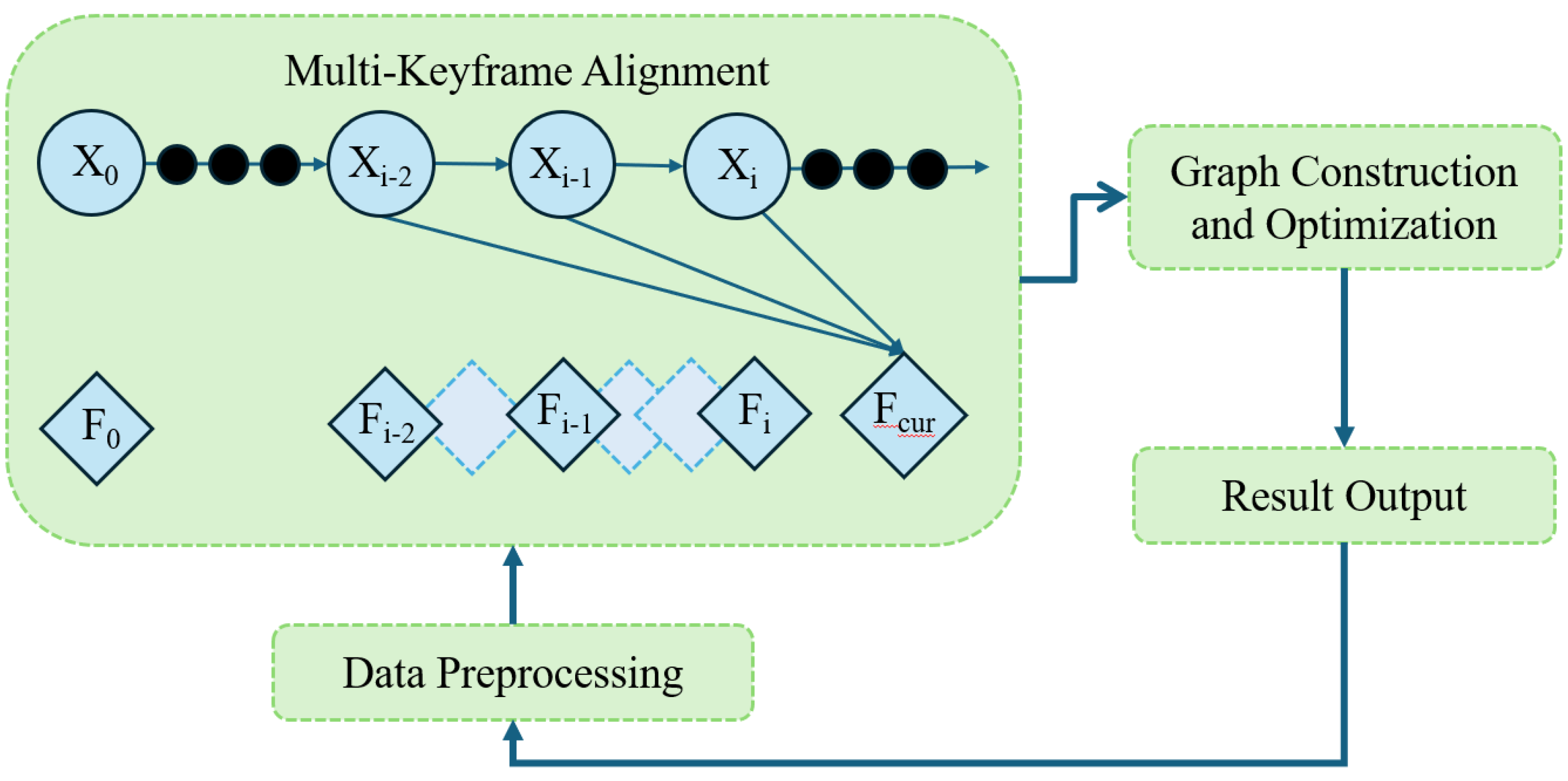
Figure 5.
Hardware framework of the UAV SLAM system.
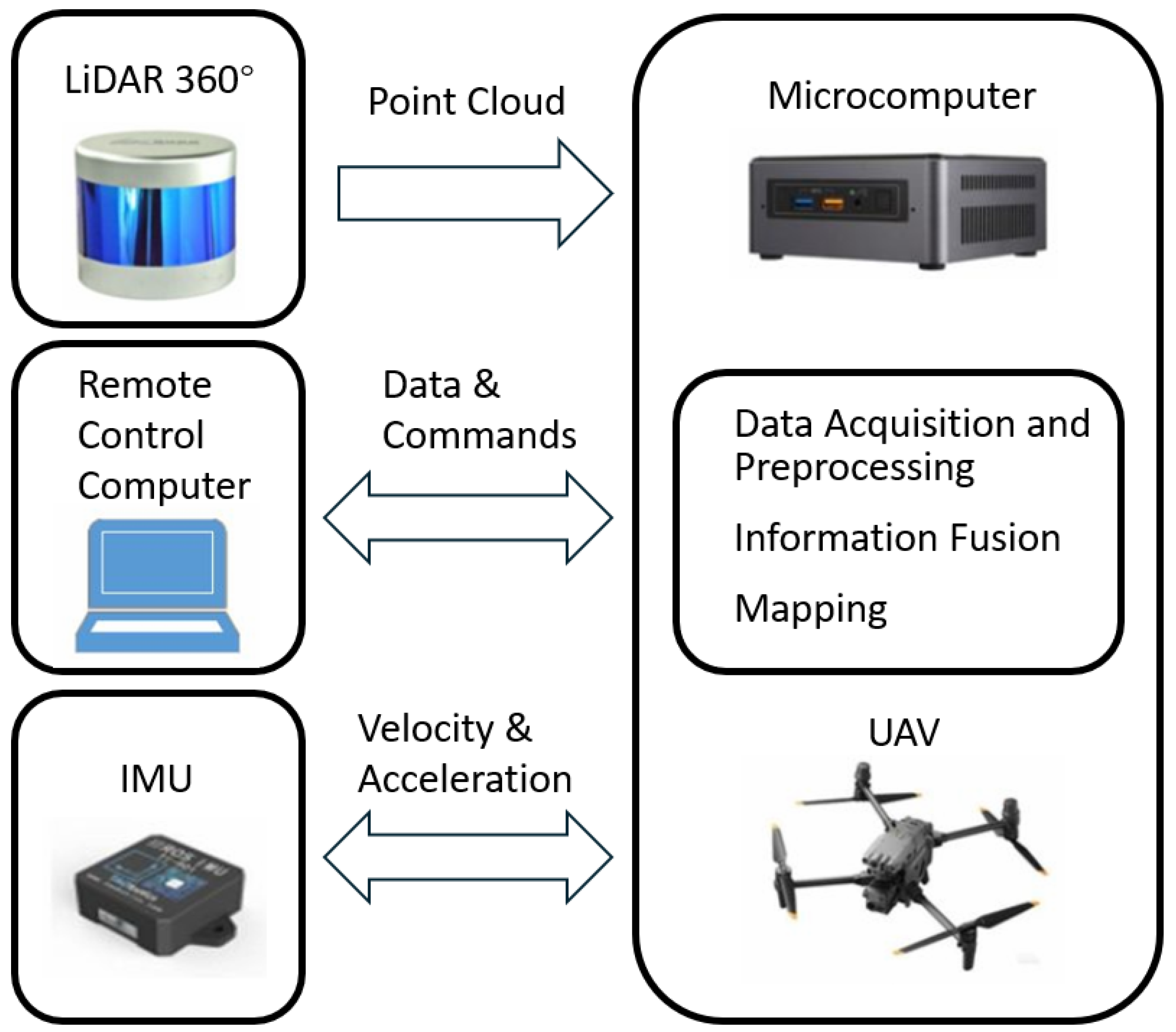
Figure 6.
3D mapping results of the UAV using the proposed algorithm.
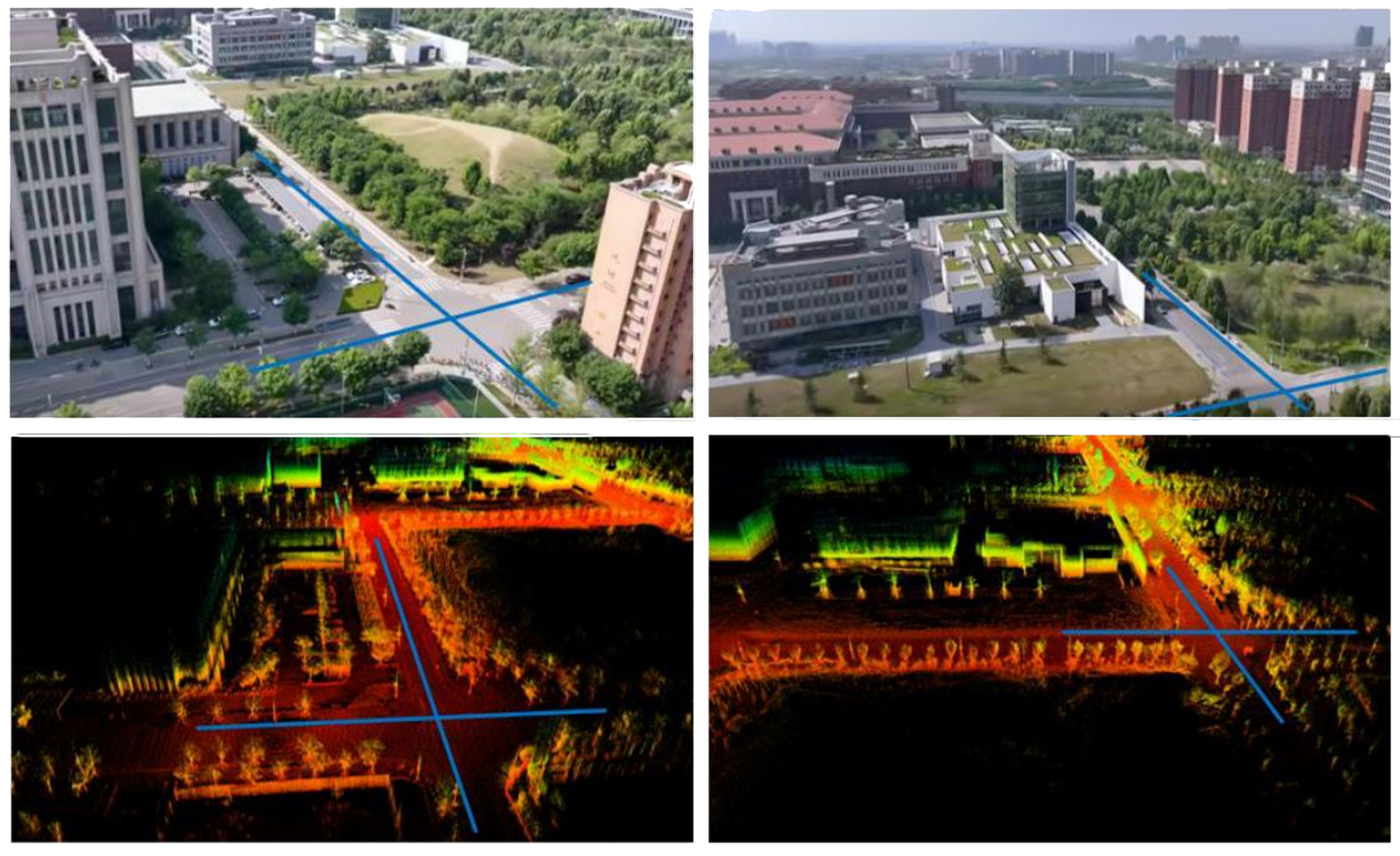
Figure 7.
UAV SLAM experimental platform.
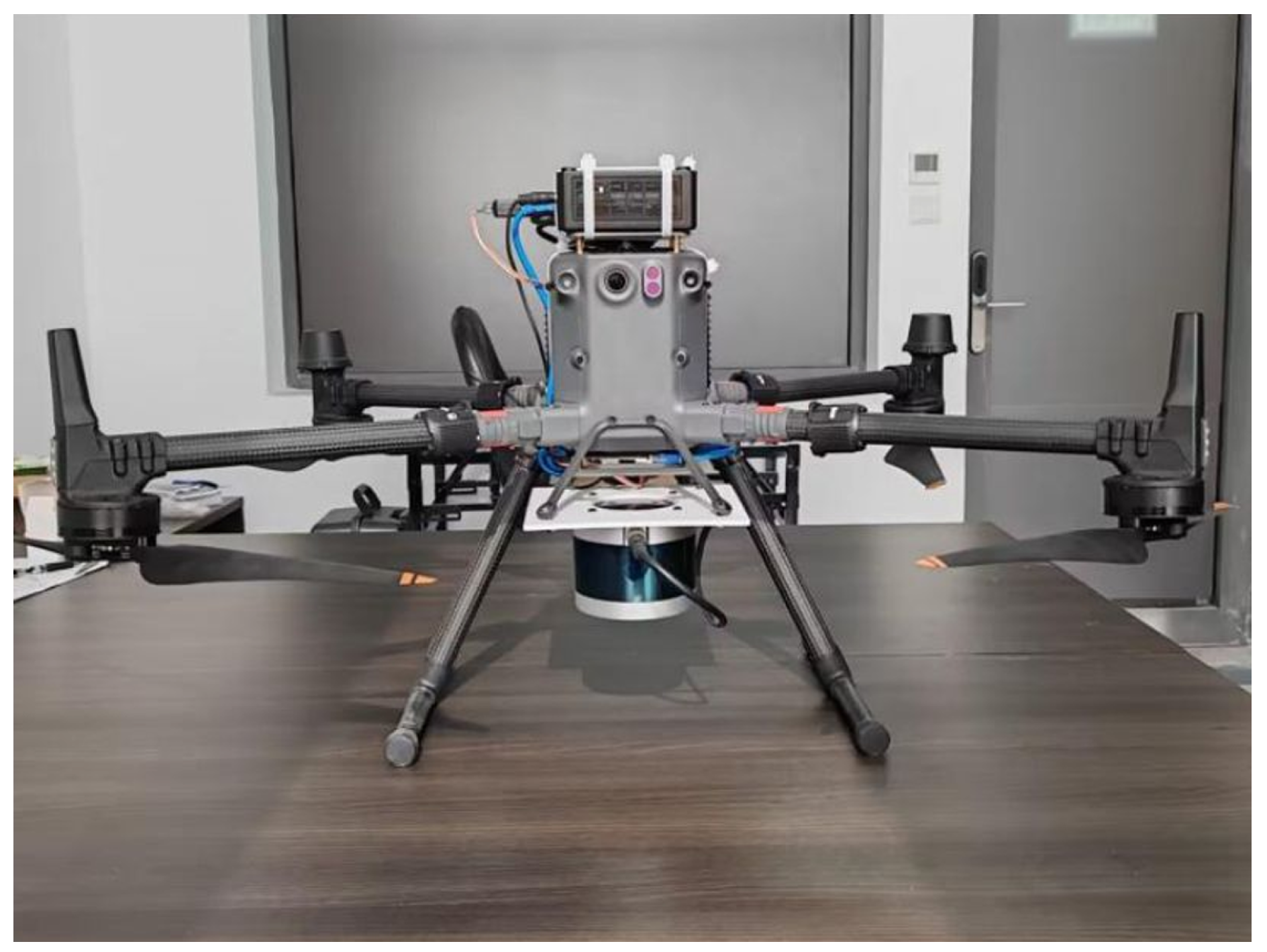
Figure 8.
Estimated UAV flight trajectory compared with the ground truth.
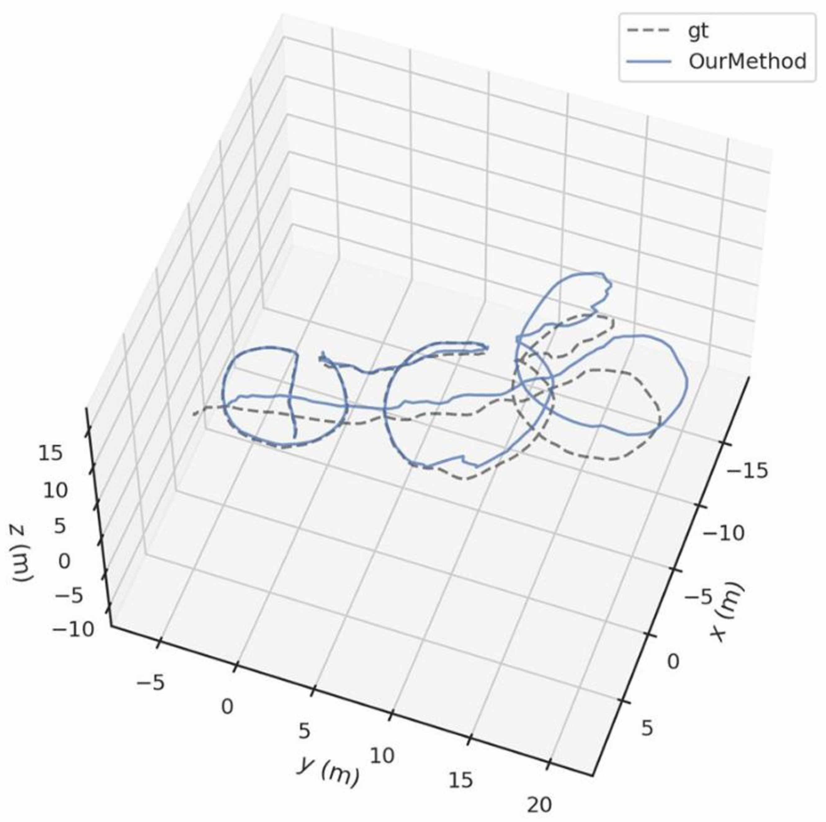

Table 1.
Outdoor trajectory and rotation errors.
| Error Type | Metric | LeGO-LOAM | Proposed Method |
|---|---|---|---|
| Trajectory (m) | RMSE | 8.00 | 2.32 |
| Mean | 6.96 | 2.06 | |
| Median | 6.96 | 2.33 | |
| Std | 3.99 | 1.07 | |
| Rotation (°) | RMSE | 45.01 | 7.06 |
| Mean | 40.32 | 6.25 | |
| Median | 52.03 | 6.15 | |
| Std | 20.02 | 3.30 |
Table 2.
Indoor trajectory and rotation errors.
| Error Type | Metric | LeGO-LOAM | Proposed Method |
|---|---|---|---|
| Trajectory (m) | RMSE | 0.49 | 0.35 |
| Mean | 0.40 | 0.27 | |
| Median | 0.36 | 0.21 | |
| Std | 0.27 | 0.17 | |
| Rotation (°) | RMSE | 2.98 | 1.71 |
| Mean | 2.08 | 1.23 | |
| Median | 1.40 | 1.10 | |
| Std | 2.13 | 1.67 |
Table 3.
Rotation and trajectory errors of the UAV experiment.
| Error Type | RMSE | Mean | Median | Std |
|---|---|---|---|---|
| Trajectory (m) | 2.50 | 2.30 | 2.40 | 1.10 |
| Rotation (°) | 10.20 | 9.00 | 9.20 | 4.00 |
Disclaimer/Publisher’s Note: The statements, opinions and data contained in all publications are solely those of the individual author(s) and contributor(s) and not of MDPI and/or the editor(s). MDPI and/or the editor(s) disclaim responsibility for any injury to people or property resulting from any ideas, methods, instructions or products referred to in the content. |
© 2026 by the authors. Licensee MDPI, Basel, Switzerland. This article is an open access article distributed under the terms and conditions of the Creative Commons Attribution (CC BY) license (http://creativecommons.org/licenses/by/4.0/).
Copyright: This open access article is published under a Creative Commons CC BY 4.0 license, which permit the free download, distribution, and reuse, provided that the author and preprint are cited in any reuse.


