
Submitted:
03 February 2026
Posted:
03 February 2026
You are already at the latest version
Abstract
In geotechnical engineering, operations such as foundation pit excavation, slope cutting, and tunnel boring often involve lateral unloading under plane strain conditions. This unloading pattern exhibits significant differences from the traditional axisymmetric triaxial loading path. To investigate the mechanical behavior of silt under such conditions, a series of plane strain tests were conducted using a self-designed plane strain apparatus, focusing on both vertical loading (constant lateral stress) and lateral unloading (constant vertical stress) paths. The results indicate that the failure of soil during unloading can be identified as the stage where the vertical deformation rate first increases and then decreases, corresponding to a distinct inflection in the stress-strain curve. The internal friction angle remained essentially constant regardless of the stress path, dry density, or consolidation stress ratio, while cohesion was higher under loading than under unloading. Failure deviatoric stress increased linearly with vertical consolidation stress and was unaffected by the consolidation stress ratio. The classical limit equilibrium condition remains valid for unloading under both isotropic and anisotropic consolidation. These findings provide a practical criterion for failure detection and highlight the necessity of adopting plane strain parameters in the design of lateral unloading engineering works.
Keywords:
plane strain
; lateral unloading
; silt
; deformation behavior
; shear strength
; failure criterion
1. Introduction
In geotechnical engineering, activities such as foundation pit excavation, slope cutting, and tunnel construction often subject the surrounding soil to lateral unloading under approximate plane strain conditions. This stress path—characterized by a constant vertical stress and a gradually decreasing lateral stress—differs fundamentally from conventional triaxial loading paths: the latter maintains constant lateral stress while increasing vertical stress, and the specimen remains in an axisymmetric state. As demonstrated by Lade [1], soil behavior is intrinsically stress-path dependent. Therefore, a dedicated investigation into the lateral unloading behavior under plane strain conditions is essential for accurate geotechnical design and analysis.
Initial research on unloading phenomena primarily relied on triaxial tests, exploring aspects such as the differences in shear strength parameters between loading and unloading paths [2,3,4], and the influences of consolidation stress [5,6] and unloading rate [7]. However, the mechanical behavior of soil under plane strain conditions differs significantly from that under the axisymmetric stress state of conventional triaxial tests, largely due to the influence of the intermediate principal stress [8,9]. Subsequently, numerous experimental and theoretical studies have been conducted to elucidate the relationship between soil properties under these two distinct stress states [10,11,12,13,14,15].
To better simulate the unloading mechanical behavior under plane strain conditions, researchers have employed specialized apparatuses. For instance, He [16] conducted lateral unloading tests using a true triaxial apparatus, while Zhuang [17] performed plane-strain unloading tests under both drained and undrained conditions, observing strain-hardening behavior in consolidated drained tests. Zhang [18,19,20] and Zhao [21] utilized a plane-strain apparatus to investigate loess, analyzing the influence of initial stress states on its strength and deformation. Ni [6] employed a modified plane strain apparatus to study silty clay, leading to a proposed model for excavation-induced earth pressure on retaining walls. Furthermore, Xu [22] explored the reinforcement mechanism of geosynthetics through plane-strain model experiments.
In the realm of theoretical and numerical analysis, Niu [23] incorporated the effects of excavation unloading into constitutive equations for plane-strain problems, deriving a method for calculating post-excavation soil displacement. Wang [24] investigated the consolidation characteristics of unsaturated soils at varying depths under plane strain conditions, and Liang [25] simulated plane strain unloading tests using the three-dimensional discrete element method.
The above analysis indicates that although significant progress has been made in studying soil behavior under plane strain conditions, most research has focused on loading paths or particular soil types. Systematic investigations into the lateral unloading behavior of silts—particularly under varying consolidation stress ratios—remain insufficient. Furthermore, explicit and practical failure criteria for unloading process under plane strain conditions have yet to be fully established. Against this backdrop, this study employs a self-developed plane strain testing apparatus to conduct systematic experimental investigations on alluvial silts from the Yellow River Plain. Tests were performed under two loading regimes: constant lateral stress with vertical loading, and constant vertical stress with lateral unloading. The research primarily examines the effects of loading/unloading paths, consolidation stress, and consolidation stress ratio on stress-strain relationships, failure stresses, and strength parameters. The research aims to establish reliable unloading failure criteria and elucidate the variation patterns of shear strength parameters, thereby providing experimental evidence and theoretical support for the analysis and design of geotechnical engineering projects involving lateral unloading, such as excavation and slope excavation.
2. Materials and Methods
2.1. Test Apparatus
The experiments were conducted using a self-designed plane strain apparatus (Patent No. ZL201510322064.8). As illustrated in Figure 1, the device consists of a rigid steel frame that confines a soil specimen of dimensions 20 mm × 100 mm × 100 mm. A transparent acrylic front panel allows for visual observation of deformation, while a fixed steel rear plate ensures zero strain in the intermediate principal stress direction. Both plates are securely bolted to maintain plane strain conditions.
Lateral stress is applied to one side of the specimen via a loading plate connected to a tensioned steel-wire system. Vertical stress is applied through a lever mechanism to the top loading plate. Stresses in both directions are increased or decreased incrementally using weights. The instrument is equipped with load cells to monitor vertical and lateral stresses, and displacement transducers to record deformations. The apparatus is characterized by its simple design, ease of operation, and low cost, while maintaining satisfactory measurement accuracy, making it suitable for laboratory use in research and industry settings.
2.2. Test Material and Procedure
The tested soil was obtained from an alluvial silt deposit in the Zhengdong New District of Zhengzhou, located on the Yellow River Plain. According to the Chinese geotechnical investigation code (GB50021-2001) [26], the soil is classified as silty sand. Its index properties are summarized in Table 1.
All specimens were remolded and prepared at a moisture content of 14% using a dedicated molding device. Following molding, specimens were saturated using the vacuum saturation method before being installed in the testing apparatus. To minimize boundary friction, the inner surfaces of the front and rear confinement plates were coated with a thin layer of Vaseline and covered with plastic film.
Since the apparatus does not permit pore pressure measurement or drainage control, all tests were conducted under consolidated-drained (CD) conditions. Consolidation was considered complete when the deformation rate fell below 0.01 mm/h. Shearing commenced immediately afterward. Two primary stress paths were investigated:
Loading Path: Lateral consolidation stress (σ30) was held constant while the vertical stress (σ1) was increased in stages.
Unloading Path: Vertical consolidation stress (σ10) was held constant while the lateral stress (σ3) was reduced in stages.
At each stress increment or decrement, loading/unloading was paused until vertical displacement rate fell below 0.01 mm per 10-minute interval, at which point the next step was applied. The initial load increment was set at 10 kPa, which was reduced to 5 kPa during the middle to late stages of shearing to better capture the pre-failure response. A schematic of the test procedure is shown in Figure 2, and the detailed test program, including variables such as stress path, consolidation state, dry density, and stress levels, is summarized in Table 2.
2.3. Failure Criteria
During loading tests, the stress-strain curves exhibited a strain-hardening pattern, as shown later in Figure 4, with no distinct peak stress observed. Therefore, a vertical strain of 15% was adopted as the failure point, and the corresponding deviatoric stress (σ1f−σ30) was defined as the failure deviatoric stress. For a detailed analysis of the loading path stress-strain curve, please refer to Section 3.1.
During unloading tests, the failure process under unloading was characterized by a distinct pattern in the deformation rate. As illustrated in Figure 3(a), the vertical deformation rate following each unloading increment typically decayed to zero during the early stage and near failure stage of the test. However, at failure, the vertical deformation rate exhibited a different response: after unloading, it initially increased, reached a peak, and then gradually decreased toward zero. This turning point coincided precisely with a clear inflection point on the deviatoric stress–strain curve, as shown in Figure 3(b). Beyond this inflection, the stress increased only minimally while the strain grew significantly, indicating a sharp reduction in the compressive modulus and a substantial weakening of the soil’s mechanical properties—i.e., the onset of failure. The vertical strain at this failure point ranged from 1% to 4% under different consolidation stresses, consistent with findings reported by Ni [6] and Li [7].
Based on the above observations, the failure under unloading was defined as the point at which the deformation rate first increased and then decreased. The lateral stress at this stage was taken as the critical lateral stress σ3f, and the corresponding deviatoric stress (σ10−σ3f) was defined as the failure deviatoric stress.
In geotechnical monitoring practices for excavations, the cumulative horizontal and vertical displacements and their daily rates of change are commonly used as early warning indicators [27]. The findings of this test suggest that failure can occur even while cumulative displacements remain relatively small. Therefore, monitoring should prioritize the rate of change of displacement. Furthermore, when evaluating the rate of change, attention should not be limited to the total daily displacement. It is crucial to observe shorter term trends (e.g., over one to two hours). An increasing rate of change may signal that soil failure is imminent, warranting immediate attention.
3. Results
3.1. Loading and Unloading Test on Isotropically Consolidated Specimens
The test results for specimens with dry densities of 1.58, 1.63, and 1.68 g/cm³ exhibited consistent trends. For conciseness, the following analysis focuses on the representative specimen with a dry density of 1.63 g/cm³.
Under the loading path (constant lateral stress, increasing vertical stress), the deviatoric stress–strain relationship displayed an approximately linear, strongly strain-hardening response, as shown in Figure 4. This is attributed to the concomitant increase in the intermediate principal stress during loading, which inhibits soil weakening. At strains below 6%, the curves for different consolidation stresses were nearly coincident and slightly concave upward, indicating a small increase in compressive modulus due to initial compaction. Beyond 6% strain, the curves diverged: at a given vertical strain, the deviatoric stress increased with higher consolidation stress, reflecting a greater compressive modulus and higher resistance to deformation.
Under unloading (constant vertical stress, decreasing lateral stress), the stress–strain curve followed a hyperbolic shape (Figure 3(b)), indicating a progressive decrease in compressive modulus and gradual weakening of the soil. Initially, for deviatoric stresses below approximately 70 kPa, deformation was negligible, and the early-stage unloading curves nearly overlapped. As the stress approached the failure condition, each curve deviated abruptly from this common trend, demonstrating a degree of brittle failure. According to the failure criterion established in Section 2.3, the vertical strain at failure ranged from 1% to 4%, increasing slightly with consolidation stress. This failure strain is markedly lower than that under loading (15%). After failure, however, the specimen could sustain additional deformation, with the final vertical strain exceeding 10% in some cases, owing to the constraining effect of the intermediate principal stress.
Under loading with consolidation stresses of 50, 75, and 100 kPa, the failure deviatoric stresses were 458, 549, and 655 kPa, respectively. Under unloading with consolidation stresses of 200, 300, and 400 kPa, the corresponding values were 170, 247, and 328 kPa. In both paths, the failure deviatoric stress increased with consolidation stress, due to a lower void ratio and denser structure after consolidation. Notably, despite the higher consolidation stresses used in the unloading tests, the failure deviatoric stresses were substantially lower than those under loading. This difference is attributed to the distinct evolution of the intermediate principal stress: it decreases during lateral unloading but increases during vertical loading.
The relationship between lateral strain and vertical strain is shown in Figure 5. All curves were nonlinear. Under loading, at a given vertical strain, lateral strain decreased as consolidation stress increased, indicating that denser specimens are more resistant to lateral deformation. Under unloading, lateral strain remained very small until the vertical strain reached about 2%, near the inflection point on the stress–strain curve. Beyond this point, lateral strain increased rapidly, signaling the approach to failure.
3.2. Unloading Tests on Anisotropically Consolidated Specimens
Anisotropic consolidation refers to the condition where the initial lateral and vertical consolidation stresses differ. This difference is quantified by the consolidation stress ratio, k=σ30/σ10. In this series, tests were conducted with k values of 0.7, 0.8, and 0.9 on specimens with a dry density of 1.63 g/cm³. As summarized in Table 3, the shear strength parameters (cohesion c and internal friction angle φ) obtained from these tests were nearly identical to those from the isotropically consolidated unloading tests. This indicates that the loading/unloading path, dry density, and consolidation stress ratio do not affect the internal friction angle, while cohesion is influenced primarily by the stress path.
Although the strength parameters remained unaffected, the consolidation stress and stress ratio significantly influenced the stress-strain response and the magnitude of the failure deviatoric stress.
3.2.1. Effect of Lateral Consolidation Stress
Similar to the isotropic consolidation tests, specimens under anisotropic consolidation exhibited the characteristic failure phenomenon where the deformation rate first increased and then decreased. Therefore, the same failure criterion was applied. The deviatoric stress-strain curves, as shown in Figure 6, displayed a hardening hyperbolic shape with a distinct inflection point. As the lateral consolidation stress increased, the failure deviatoric stress rose progressively, while the corresponding vertical strain at failure showed only a minor increase, consistent with the trend observed under isotropic conditions.
3.2.2. Effect of Consolidation Stress Ratio
The influence of the consolidation stress ratio k on the stress-strain relationship is shown in Figure 7 (using data for σ30= 200 kPa as an example). When the deviatoric stress was below approximately 100 kPa, vertical strain was negligible. Beyond this threshold, deformation increased markedly. At a given vertical strain, a smaller consolidation stress ratio (implying a higher vertical consolidation stress for a fixed σ30) resulted in a larger deviatoric stress. This is attributed to the higher total consolidation stress, which produces a denser, stiffer specimen requiring greater stress to achieve the same deformation.
The combined effects of lateral consolidation stress and consolidation stress ratio on the failure deviatoric stress are presented in Figure 8. The failure deviatoric stress increased linearly with lateral consolidation stress, with the slope of this linear relationship varying with the consolidation stress ratio. For a constant lateral consolidation stress, the failure deviatoric stress increased as the consolidation stress ratio decreased (i.e., as the vertical consolidation stress increased). This confirms that the total consolidation stress (σ30+σ10) is a important factor governing the failure stress under unloading. The relationship between the failure deviatoric stress and the sum of consolidation stresses is plotted in Figure 9.
As shown in Figure 9, the failure deviatoric stress increases periodically with the sum of consolidation stresses. With lateral consolidation stresses of 200, 300, and 400 kPa, the test points are correspondingly divided into three zones. Within each zone, the deviatoric stress increases linearly with the sum of consolidation stresses, and the distribution of test points across the three zones is nearly parallel. Subtracting the lateral consolidation stress from the horizontal coordinate of each zone reveals the relationship between the deviatoric stress at failure and the vertical consolidation stress, as shown in Figure 10.
3.2.3. Effect of Vertical Consolidation Stress
Figure 10 shows that the deviatoric stress at failure increases linearly with vertical consolidation stress and is unaffected by the consolidation stress ratio. This indicates that the anisotropy during consolidation does not influence the relationship between deviatoric stress at failure and vertical consolidation stress.
3.3. Shear Strength Parameters
The shear strength parameters obtained from loading and unloading tests are summarized in Table 3.
As shown in the table, the internal friction angle remains essentially constant under all tested conditions, with values approximately equal to 41° for both loading and unloading paths. This parameter is unaffected by dry density, consolidation state, or consolidation stress ratio. Such behavior is consistent with the critical state soil mechanics framework, wherein the internal friction angle is fundamentally governed by the mineral composition, particle shape, and gradation of the soil, and is independent of initial density or stress history once the critical state is reached.
In contrast, cohesion is clearly influenced by the stress path. Under the loading path, cohesion ranges between 43.9 and 66.4 kPa and increases with dry density. Under the unloading path, cohesion is significantly lower, ranging between 10.6 and 15.0 kPa, and does not exhibit a clear dependence on dry density. This difference highlights that soil strength under loading exceeds that under unloading, a result attributable to the distinct evolution of the intermediate principal stress: it increases during loading, thereby enhancing shear resistance, but decreases during unloading, leading to lower mobilized cohesion. Consequently, strength parameters derived from conventional loading tests should not be directly applied to the design of engineering works involving lateral unloading, as this would lead to unsafe predictions.
It is noteworthy that the internal friction angles obtained in this study are consistently higher than those typically reported from conventional triaxial compression tests on similar soils, where values generally range between 25° and 36° [28,29]. As indicated by Zhu [30], such differences can exceed 30%. This discrepancy arises from the fundamental difference in the intermediate principal stress condition: in triaxial tests, the intermediate and minor principal stresses are equal, whereas in plane strain tests, zero strain is enforced in the intermediate principal stress direction, resulting in a higher intermediate principal stress that enhances the apparent strength of the soil.
3.4. Limit Equilibrium Conditions Under Unloading Paths
The observed behavior can be explained theoretically as follows. In the lateral unloading tests, the vertical consolidation stress remains constant while the lateral stress gradually decreases. The corresponding change in the stress state is represented by the Mohr circles shown in Figure 11, where Circle I denotes the initial state after consolidation and Circle II represents the state at failure. Based on the geometric relationship at failure, Equation (1) is obtained[31].
Rearranging this equation yields Equation (2).
Given that the values of cohesion c and internal friction angle φ obtained under different consolidation conditions are nearly identical, Equation (2) indicates that the failure deviatoric stress (σ10−σ3f) increases linearly with the vertical consolidation stress σ10, and this relationship is independent of the consolidation stress ratio k. Substituting the average values of c and φ from Table 3 into Equation (2) yields the theoretical straight line plotted in Figure 10.
During the unloading test, the vertical consolidation stress remains constant, but the lateral stress is not held constant after consolidation; instead, it is progressively reduced. Substituting k=σ30 /σ10 into Equation (2) leads to Equation (3).
This shows that, for given values of c and φ, the relationship between the failure deviatoric stress (σ10−σ3f) and the lateral consolidation stress σ30 depends on k. For different values of k, distinct linear relationships are obtained, corresponding to the theoretical lines plotted in Figure 8.
The experimental relationship between σ3f and σ10 is shown in Figure 12. The lateral stress at failure increases linearly with the vertical consolidation stress, and this linear trend is unaffected by the consolidation stress ratio k. Rearranging Equation (2) gives Equation (4).
The calculated results, presented in Figure 12, show good agreement with the experimental data. Equation (4) is the classical limit equilibrium condition formula in soil mechanics[31]. Previous studies did not account for the influence of the consolidation stress ratio during unloading. This study demonstrates, both experimentally and theoretically, that the same formula remains applicable to the unloading process under anisotropic consolidation conditions. Therefore, in lateral unloading engineering, provided the values of c and φ are unaffected by k, the lateral stress at failure σ3f can be determined using Equation (4), regardless of whether the soil is initially isotropically or anisotropically consolidated. When the lateral load approaches this critical value, it indicates that soil failure may be imminent and warrants immediate attention.
4. Discussion
(1)Engineering implications of the proposed unloading failure criterion
The failure criterion proposed in this study—identified as the stage where the deformation rate first increases and then decreases—aligns well with the characteristic inflection point in the deviatoric stress–strain curve. This correspondence provides a mechanistic basis for deformation-rate-based monitoring, a practice already common in geotechnical engineering for excavations and slopes. The results emphasize that even when cumulative displacements remain small, a rising deformation rate over short time intervals (e.g., one to two hours) can signal impending failure. Consequently, monitoring should prioritize tracking short-term rate trends alongside conventional daily displacement thresholds, thereby enabling earlier and more reliable warnings in lateral unloading scenarios.
(2)Role of the intermediate principal stress
The influence of the intermediate principal stress is central to interpreting the observed responses under plane-strain conditions. All key experimental trends—including the absence of peak/softening in loading, the capacity for substantial post-failure deformation in unloading, the higher failure deviatoric stress and cohesion under loading compared to unloading—can be attributed to the evolution of the intermediate principal stress. During loading, the increase in intermediate principal stress enhances confinement and strength; during unloading, its reduction promotes a loss of confinement and earlier failure. As the current apparatus does not directly measure the intermediate stress, quantitative relationships between its magnitude and the mechanical response remain to be established in future work.
(3)Applicability of the test apparatus and directions for improvement
The self-designed plane strain apparatus employed in this study offers a simple, cost-effective and operable solution for laboratory investigations, making it particularly suitable for research institutes and construction companies. Its limitation, however, lies in the inability to measure the intermediate principal stress, which restricts a full quantitative analysis of the three-dimensional stress evolution. Future improvements could focus on integrating sensors capable of monitoring the intermediate stress. Such an enhancement would allow a more complete characterization of soil behavior under plane strain conditions and facilitate the development of more refined constitutive models.
5. Conclusions
This study systematically investigated the deformation and strength behavior of alluvial silt under plane strain conditions, with particular focus on lateral unloading. The main conclusions are summarized as follows:
(1) A practical failure criterion for plane strain unloading is established. Failure is identified as the stage where the vertical deformation rate first increases and then decreases, which corresponds to a distinct inflection point in the stress–strain curve and a sharp increase in lateral strain. This criterion aligns closely with deformation-rate monitoring in geotechnical practice and supports early warning based on short-term displacement trends.
(2) The stress–strain response is strongly path-dependent. Under loading with constant lateral stress, the behavior is nearly linear and strain-hardening, with higher consolidation stress leading to greater stiffness and reduced lateral deformation. Under unloading with constant vertical stress, the response shows progressive softening, and failure occurs at relatively small vertical strain (1–4%), although considerable post-failure deformation may follow due to the constraining effect of the intermediate principal stress.
(3) The internal friction angle remains essentially constant (approximately 41°) and is unaffected by stress path, dry density, or consolidation stress ratio. In contrast, cohesion is path-sensitive: it is significantly higher under loading than under unloading and increases with dry density under loading. These results underscore that strength parameters derived from conventional loading tests should not be directly adopted in the design of lateral-unloading engineering works.
(4) The failure deviatoric stress increases linearly with vertical consolidation stress and is independent of the consolidation stress ratio. Its relationship with lateral consolidation stress, however, varies with the consolidation stress ratio. The experimental data are well described by the Mohr–Coulomb failure criterion, confirming that the classical limit equilibrium condition remains valid for unloading under both isotropic and anisotropic consolidation.
Overall, the findings highlight the necessity of using plane strain parameters—rather than conventional triaxial data—in the analysis and design of geotechnical structures involving lateral unloading, such as excavations, slopes, and tunnels. The proposed failure criterion and the clarified dependencies of strength and deformation on stress path provide practical guidance for both laboratory characterization and field monitoring.
Funding
This research was funded by the 2025 Annual Henan Provincial Key Scientific and Technological Research Project of China(No. 252102321018)
References
- Lade, P. V.; Duncan, J. M. Stress path dependent behavior of cohesionless Soil. J. Geotech. Eng. 1976, 102, 51–68. [Google Scholar] [CrossRef]
- Zhou, Q. J.; Chen, X. P. Test research on typical mechanical characteristics of soft clay under lateral unloading condition. Chin. J. Rock Mech. Eng. 2009, 28, 2215–2221. [Google Scholar]
- Yuan, J. P.; Nguyen, H. V. Laboratory study on soil shear stiffness and strength under unloading conditions. J. Test. Eva. 2011, 39, 2215–2221. [Google Scholar] [CrossRef]
- Liu, X. Y.; Yan, S. W.; Dou, Y. M. Experimental studies of simulated excavation process. Rock Soil Mech. 2005, 26, 97–104. [Google Scholar]
- Chen, S. H.; Ling, P. P.; He, S. X. Experimental study on deformation behavior of silty clay under unloading. Rock Soil Mech. 2007, 28, 2534–2538. [Google Scholar]
- Ni, P. P.; Mei, G. X.; Zhao, Y. L. Plane strain evaluation of stress paths for supported excavations under lateral loading and unloading. Soils Founda. 2018, 58, 146–159. [Google Scholar] [CrossRef]
- Li, L.; Zang, M.; Zhang, R. T.; Lu, H. J. Experimental Study on Mechanical Properties of Structured Clay under Different unloading Rates and Unloading Stress Paths. Buildings 2023, 13, 1544. [Google Scholar] [CrossRef]
- Li, G. X.; Huang, Y. N.; Zhang, Q. G. The principal stress of soil in the direction of plane strain. Chin. J. Geotech. Eng. 2001, 23, 358–361. [Google Scholar]
- Zhang, H. P.; Ma, Q. Y.; Huang, K. Strength and deformation analysis of frozen sand under different stress paths using triaxial test. Rock Soil Mech. 2023, 44, 1477–1486, 1500. [Google Scholar]
- Luo, T.; Yao, Y. P.; Matsuoka, H. Soil strength equation in plane strain based on SMP. Rock Soil Mech. 2000, 21, 390–393. [Google Scholar]
- Adel, H. Determination of plane-strain shear strength of sand from the results of triaxial tests. Can. Geotech. J. 2001, 38, 1231–1240. [Google Scholar] [CrossRef]
- Shi, W. C.; Zhu, J. G.; Zhang, B. Strength characteristics of coarse-grained soil under plane strain condition. Chin. J. Geotech. Eng. 2011, 33, 1974–1979. [Google Scholar]
- Hu, H. X.; Yao, Y. P.; Luo, T. Soil strength equation under plane strain condition based on Lade-Duncan criterion. Rock Soil Mech. 2022, 43(Supp. 1), 389–396. [Google Scholar]
- Li, C. Description of strength characteristics of soil under plane strain condition based on MNLD criterion. J. Rail. Sci. Eng. 2019, 16, 1955–1960. [Google Scholar]
- Li, B. P.; He, R.; Zhang, Y. Calculation and applicability of earth pressure based on elastic theory under plane strain conditions. Chin. Earthquake Eng. J. 2023, 45, 673–680. [Google Scholar]
- He, S. X.; Zhu, Z. Z.; Yang, X. Q. A study of true triaxial test on lateral unloading of soil mass of foundation pit. Rock Soil Mech. 2005, 26, 869–892. [Google Scholar]
- Zhuang, X. S.; Zhao, X.; He, S. X. An experimental study of soil mass deformability subject to true triaxial loads during unloading under drainage. Rock Soil Mech. 2007, 28, 1387–1390. [Google Scholar]
- Zhang, Y.; Fan, T. J.; Xu, C. Y. Study on structure evolution characteristics of undisturbed Q3 loess under plane-strain condition. Chin. Civ. Eng. J. 2022, 55, 65–77. [Google Scholar]
- Zhang, Y.; Xu, C. Y.; Fan, T. J. Improvement and validation of a newly developed plane strain apparatus based on true triaxial testing. J. Test. Eva. 2023, 51, JTE20220370. [Google Scholar] [CrossRef]
- Zhang, Y.; Zhao, Y.; Liu, K. J. Mechanical characteristics of plane strain unloading conditions with different initial states. Chin. J. Geotech. Eng. 2024, 46, 162–173. [Google Scholar]
- Zhao, Y. Study on structural evolution and mechanical properties of Loess under plane strain unloading conditions. Master’s Thesis, Xi'an Technological University, Xi’an, China, 2022. [Google Scholar]
- Xu, C.; Liang, C.; Shen, P. P. Experimental and numerical studies on the reinforcing mechanisms of geosynthetic-reinforced granular soil under a plane strain condition. Soils Founda. 2020, 60, 466–477. [Google Scholar] [CrossRef]
- Niu, J. D.; Li, Z. W.; Xiao, J. Deformation calculation and supporting performance of foundation pit considering stress path. J. Rail. Sci. Eng. 2021, 18, 71–80. [Google Scholar]
- Wang, L.; Shen, S. D.; Li, T. Y. Two-dimensional plane strain consolidation of unsaturated soils considering the depth-dependent stress. J. Rock Mech. Geotech. Eng. 2023, 15, 1603–1614. [Google Scholar] [CrossRef]
- Liang, L. J.; Xu, C. J.; Fan, X. Z. Hyperbolic stress-strain behaviour of sandy soil under plane strain unloading condition and its application on predicting displacement-dependent active earth pressure. Comput. Geotech. 2023, 155, 1–13. [Google Scholar] [CrossRef]
- GB50021-2001; Code for investigation of geotechnical engineering. China Architecture ang Building Press: Beijing, China, 2009.
- GB50497-2009; Technical code for monitoring of building foundation pit engineering. China planning press: Beijing, China, 2009.
- Wu, Q. X.; Peng, L. Y.; Long, P. H. Study of modifying silt by lime and cement. Highway 2015, 60(9), 14–19. [Google Scholar]
- Ma, X. Y.; Qian, Y.; Xuan, M. M.; Ren, H. P.; Ye, X. Y.; Liu, B. Study on the Influence Mechanism of Sample Preparation Method on the Shear Strength of Silty Soil. Sustainability 2023, 15(3), 2635. [Google Scholar] [CrossRef]
- Zhu, S. Z.; Liu, Q.; Bao, C. G. Triaxial test principle and application technology; China Electric Power Press: Beijing, China, 2003. [Google Scholar]
- Knappett, J. A.; Craig, R. F. Craig's Soil Mechanics, 8th ed.; Spon Press: London, UK, 2012. [Google Scholar]
Figure 1.
Self-designed plane strain apparatus and sample preparation tool: (a) schematic of the apparatus; (b) specimen molding device.
Figure 1.
Self-designed plane strain apparatus and sample preparation tool: (a) schematic of the apparatus; (b) specimen molding device.
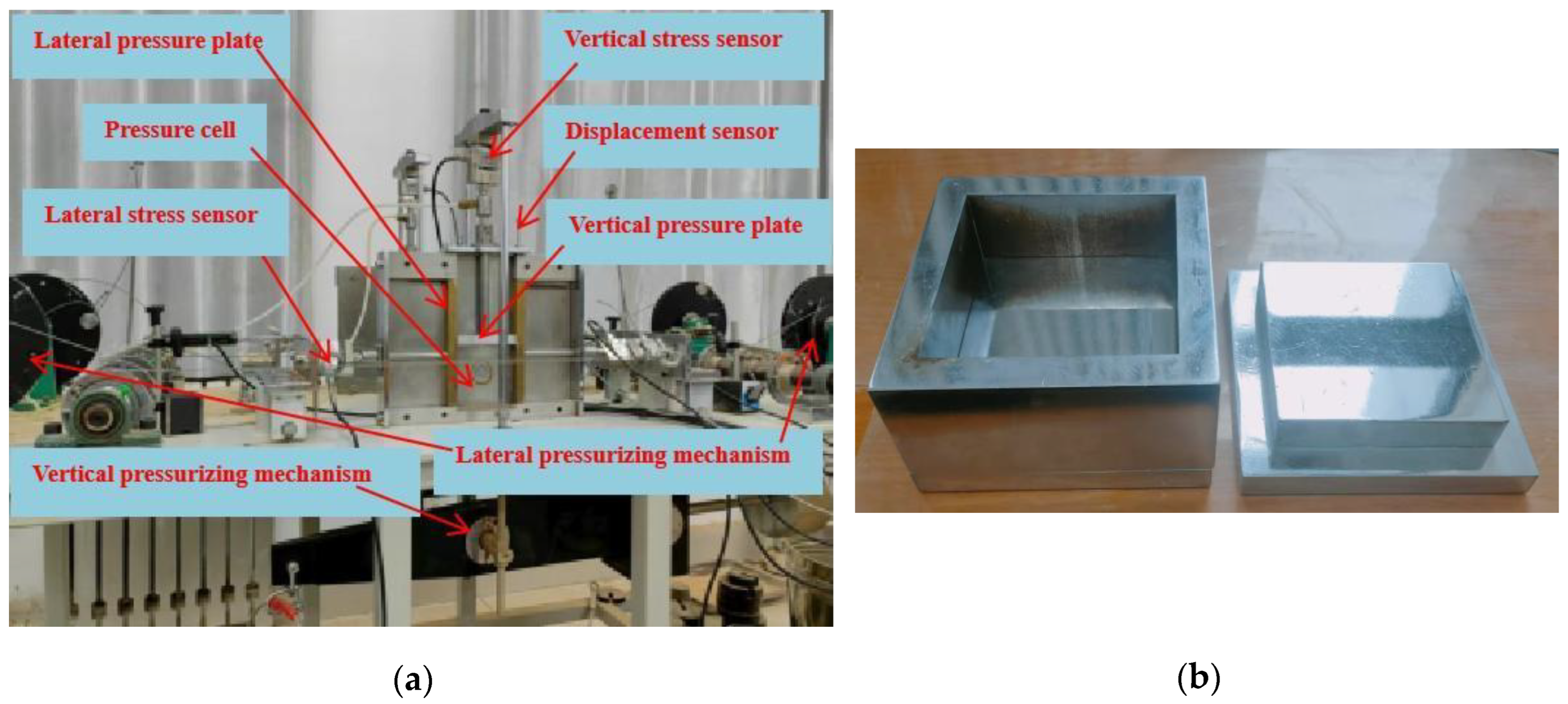
Figure 2.
Schematic diagram of the experimental procedure for loading and unloading tests.
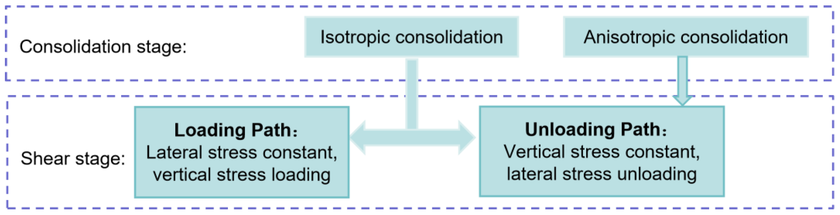
Figure 3.
Typical response of silt under plane strain unloading: (a) evolution of vertical deformation rate with time; (b) deviatoric stress–strain relationship with failure point.
Figure 3.
Typical response of silt under plane strain unloading: (a) evolution of vertical deformation rate with time; (b) deviatoric stress–strain relationship with failure point.
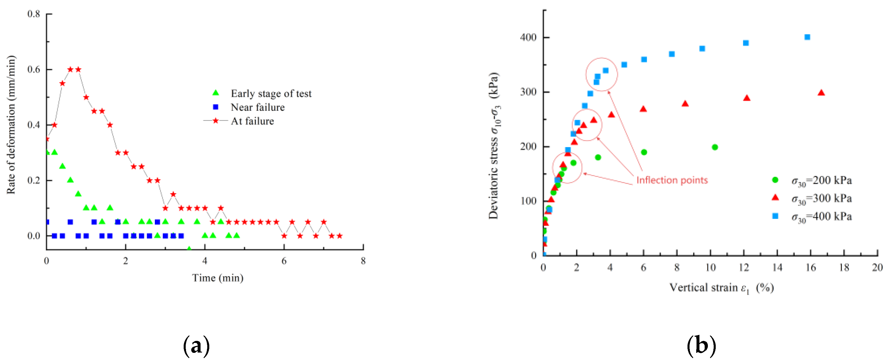
Figure 4.
Deviatoric stress–strain curves of silt under loading path with different consolidation stresses.
Figure 4.
Deviatoric stress–strain curves of silt under loading path with different consolidation stresses.
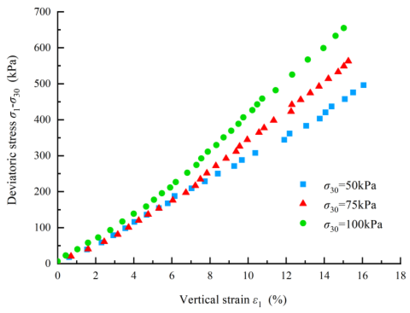
Figure 5.
Relationship between lateral strain and vertical strain: (a) loading path; (b) unloading path.
Figure 5.
Relationship between lateral strain and vertical strain: (a) loading path; (b) unloading path.
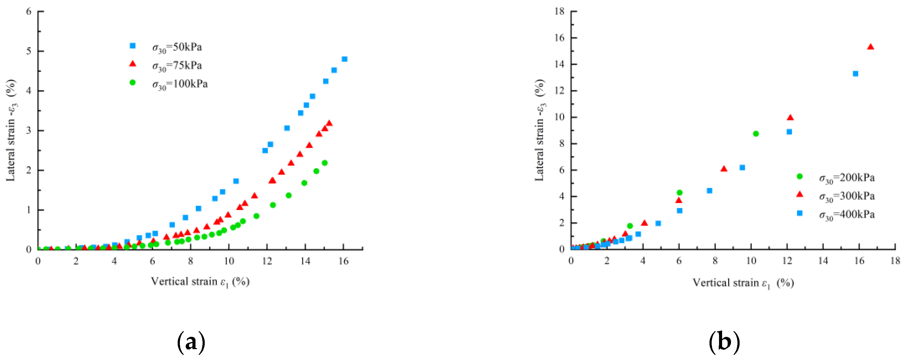
Figure 6.
Deviatoric stress–strain curves under anisotropic consolidation unloading with different lateral consolidation stresses: (a) k=0.7; (b) k=0.8; (c) k=0.9.
Figure 6.
Deviatoric stress–strain curves under anisotropic consolidation unloading with different lateral consolidation stresses: (a) k=0.7; (b) k=0.8; (c) k=0.9.
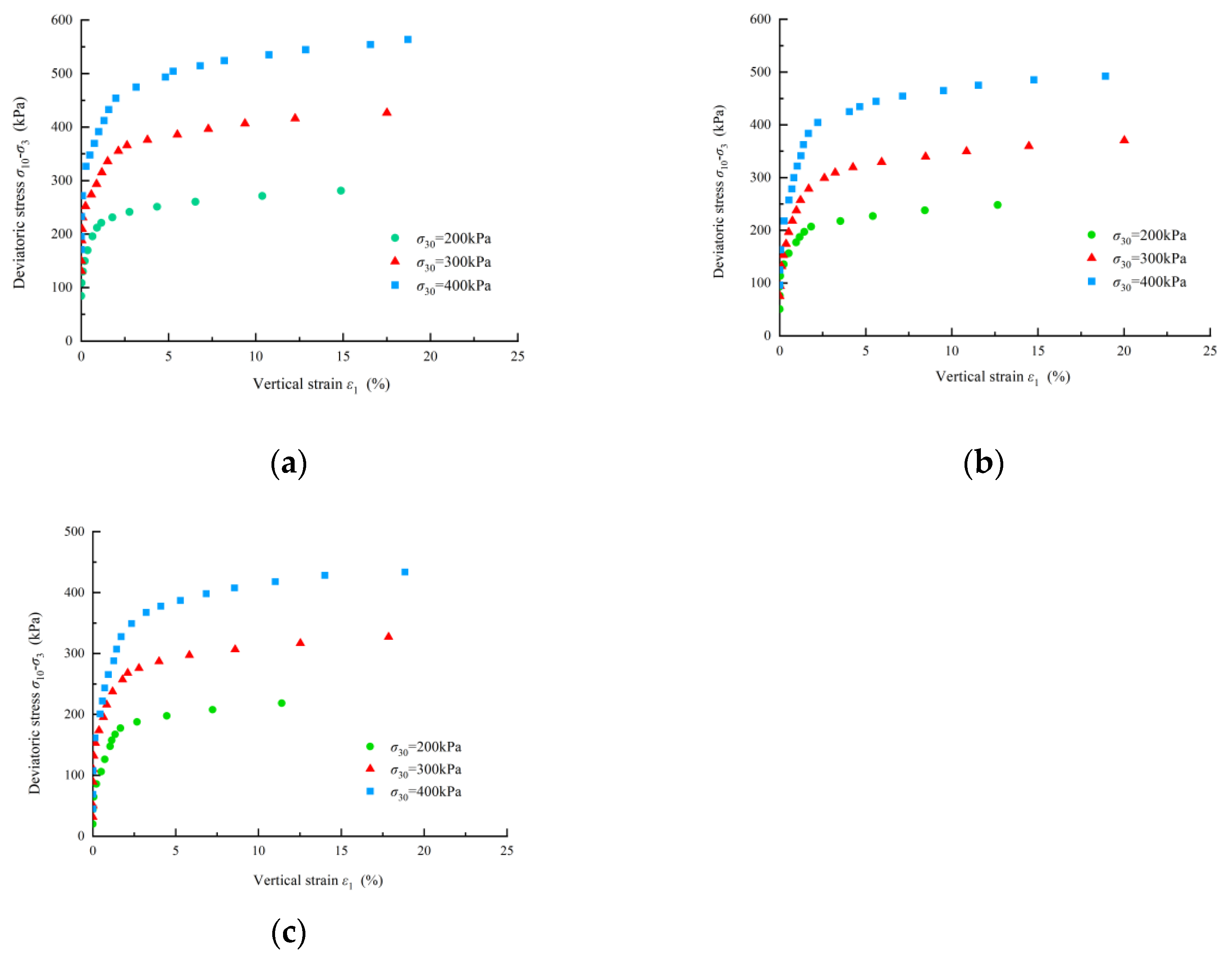
Figure 7.
Influence of consolidation stress ratio k on deviatoric stress–strain behavior under constant lateral consolidation stress (σ30=200 kPa).
Figure 7.
Influence of consolidation stress ratio k on deviatoric stress–strain behavior under constant lateral consolidation stress (σ30=200 kPa).
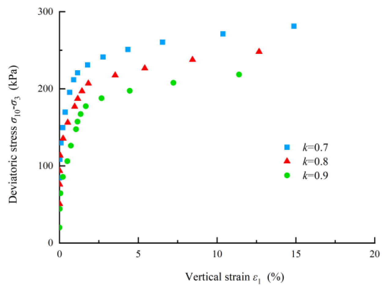
Figure 8.
Variation of failure deviatoric stress with lateral consolidation stress under different consolidation stress ratios.
Figure 8.
Variation of failure deviatoric stress with lateral consolidation stress under different consolidation stress ratios.
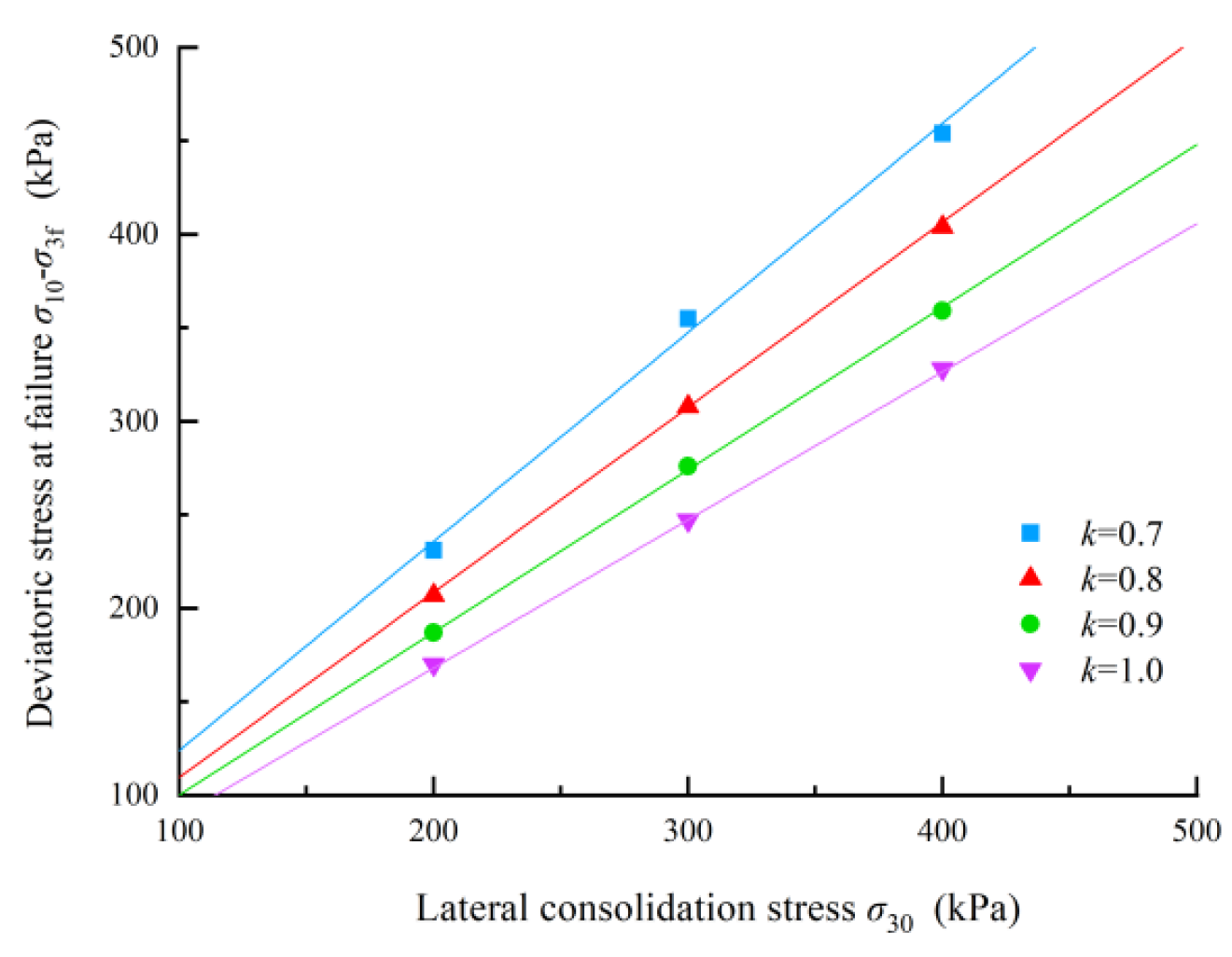
Figure 9.
Relationship between failure deviatoric stress and the sum of consolidation stresses under unloading conditions.
Figure 9.
Relationship between failure deviatoric stress and the sum of consolidation stresses under unloading conditions.
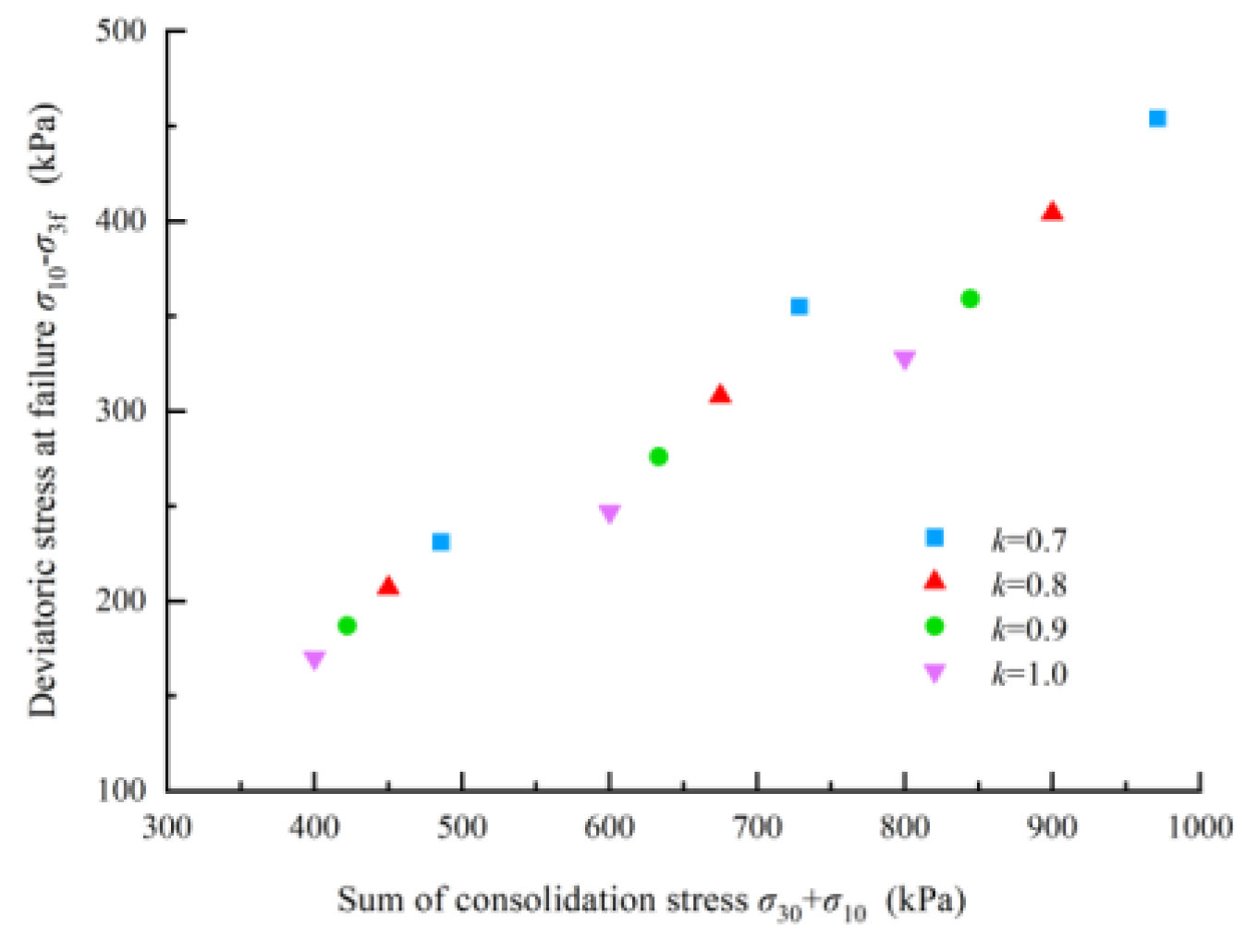
Figure 10.
Linear relationship between failure deviatoric stress and vertical consolidation stress.
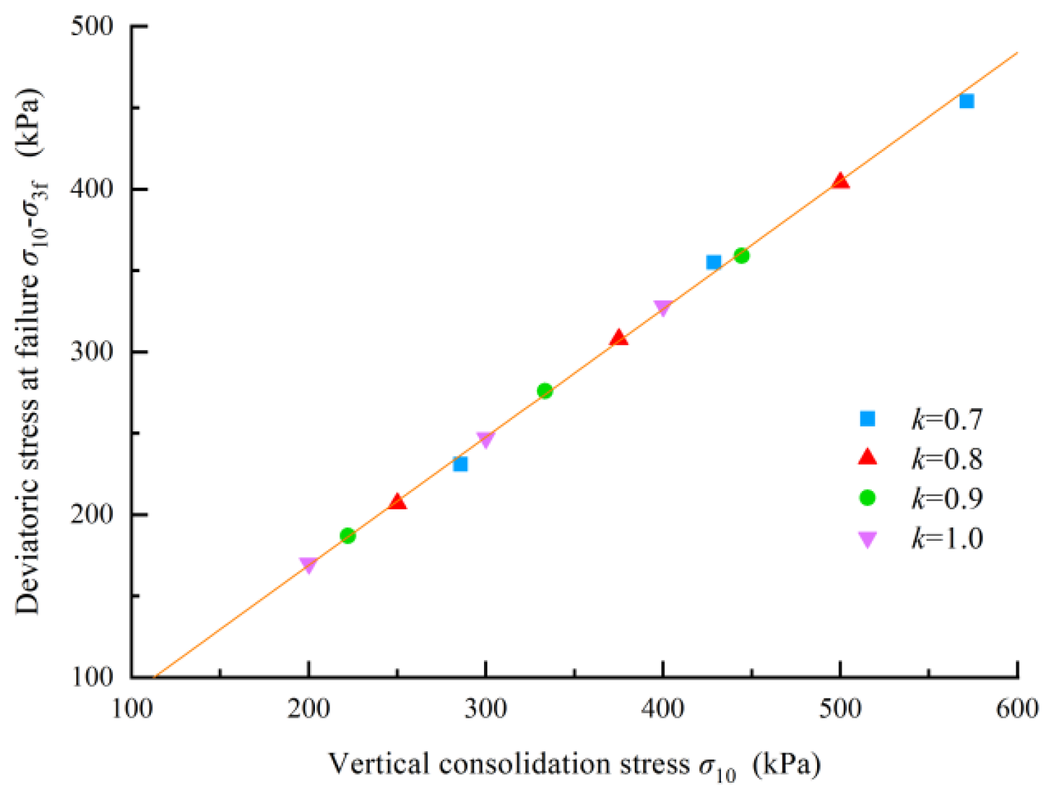
Figure 11.
Mohr circles representing stress states at initial consolidation and failure during lateral unloading.
Figure 11.
Mohr circles representing stress states at initial consolidation and failure during lateral unloading.
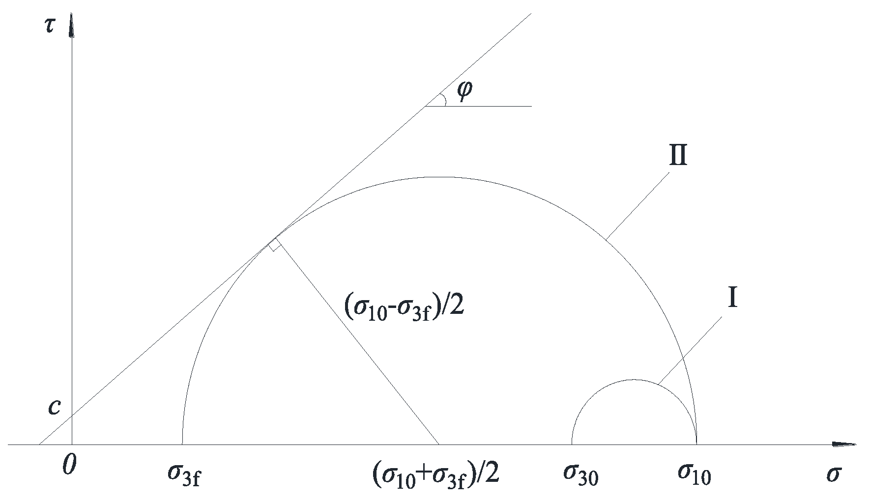
Figure 12.
Relationship between lateral stress at failure and vertical consolidation stress under different consolidation stress ratio.
Figure 12.
Relationship between lateral stress at failure and vertical consolidation stress under different consolidation stress ratio.
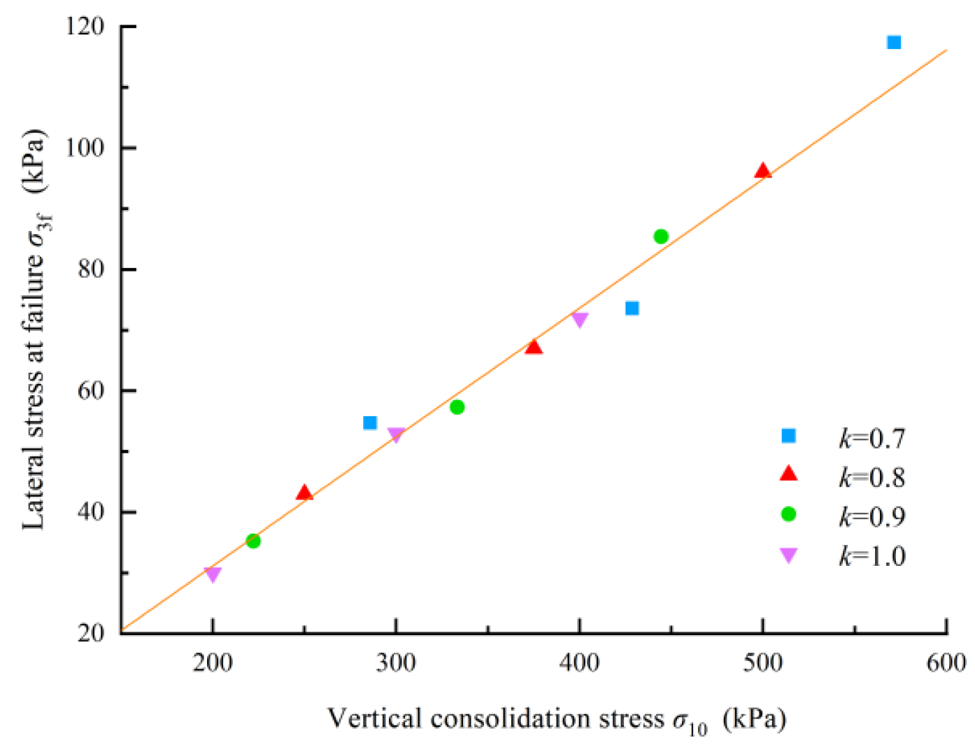

Table 1.
Physical properties of the tested silty soil.
| Specific gravity | Maximum dry density(g/cm3) | Optimum moisture content(%) | Plastic limit(%) | Liquid limit(%) | Plasticity index |
|---|---|---|---|---|---|
| 2.71 | 1.80 | 15.6 | 14.2 | 23.8 | 9.6 |
Table 2.
Test program for plane strain loading and unloading experiments
| Stress path | Consolidation state | Consolidation stress ratio k * | Dry density ρd (g/cm3) |
Lateral consolidation stress σ30(kPa) | Vertical consolidation stress σ10(kPa) |
|---|---|---|---|---|---|
| Loading Path | Isotropic consolidation | 1 | 1.58, 1.63, 1.68 | 50 | 50 |
| 75 | 75 | ||||
| 100 | 100 | ||||
| Unloading Path | Isotropic consolidation |
1 |
1.58, 1.63, 1.68 |
200 | 200 |
| 300 | 300 | ||||
| 400 | 400 | ||||
| Anisotropic consolidation | 0.9 |
1.63 |
200 | 222 | |
| 300 | 333 | ||||
| 400 | 444 | ||||
| 0.8 |
1.63 |
200 | 250 | ||
| 300 | 375 | ||||
| 400 | 500 | ||||
| 0.7 | 1.63 | 200 | 286 | ||
| 300 | 429 | ||||
| 400 | 571 |
* Consolidation stress ratio k is the ratio of later consolidation stress to vertical consolidation stress.
Table 3.
Summary of shear strength parameters under different testing conditions
| Stress path | Consolidation state | Consolidation stress ratio k | Dry density ρd (g/cm3) |
Cohesion c(kPa) | Internal friction angle φ(°) |
|---|---|---|---|---|---|
| Loading Test |
Isotropic consolidation |
1 | 1.58 | 43.9 | 41 |
| 1.63 | 60.0 | 41 | |||
| 1.68 | 66.4 | 41 | |||
| Unloading Test | Isotropic consolidation |
1 | 1.58 | 13.2 | 40 |
| 1.63 | 10.6 | 41 | |||
| 1.68 | 15.0 | 40 | |||
| Anisotropic consolidation | 0.9 | 1.63 | 14.0 | 40 | |
| 0.8 | 1.63 | 11.5 | 41 | ||
| 0.7 | 1.63 | 13.0 | 40 |
Disclaimer/Publisher’s Note: The statements, opinions and data contained in all publications are solely those of the individual author(s) and contributor(s) and not of MDPI and/or the editor(s). MDPI and/or the editor(s) disclaim responsibility for any injury to people or property resulting from any ideas, methods, instructions or products referred to in the content. |
© 2026 by the authors. Licensee MDPI, Basel, Switzerland. This article is an open access article distributed under the terms and conditions of the Creative Commons Attribution (CC BY) license (http://creativecommons.org/licenses/by/4.0/).
Copyright: This open access article is published under a Creative Commons CC BY 4.0 license, which permit the free download, distribution, and reuse, provided that the author and preprint are cited in any reuse.


