Submitted:
02 February 2026
Posted:
03 February 2026
You are already at the latest version
Abstract
The growing need for reliable, efficient power conversion in high-voltage, high-power applications has accelerated the development of new converter topologies and control methods. This paper provides a comprehensive analysis of multicellular (series multicell) converters, focusing on their topologies, mathematical modeling, and advanced control methods in both chopper and inverter setups. The multicellular converter topology offers many advantages, including distributed voltage stress, modularity, improved output waveform quality, and enhanced dynamic performance. However, to ensure the system runs smoothly, it needs advanced control systems to maintain balanced floating-capacitor voltage and respond effectively to changing or disturbed conditions. Two mathematical modelling approaches—instantaneous and average value models—are developed for the series multi-cell converter. Building on these, three control strategies are proposed and analyzed: open-loop natural balancing, closed-loop proportional-integral (PI) regulation for floating capacitor voltages, and a robust sliding-mode control integrating decoupled current and voltage regulation. The phase-shifted pulse-width modulation method is used to implement these controllers, and detailed MATLAB/Simulink simulations of a three-cell converter driving an R-L load are used to test them. The results show that advanced control techniques have led to significant improvements, including faster dynamic response, better voltage balancing, less variation in output voltage and current, and greater resistance to disturbances. The paper lays the groundwork for the use of multicellular converters in renewable energy systems. Future work will focus on integrating a three-arm inverter into wind turbine conversion chains, further reducing control chattering and testing performance in real-world conditions.
Keywords:
multicellular converter
; proportional-integral (PI) control
; decoupling control
; sliding mode control (SMC)
; wind turbine conversion chain
1. Introduction
Power electronics has advanced significantly due to the increasing demand for high-power, high-efficiency, and reliable power conversion systems across applications such as industrial drives, electric vehicles, and renewable energy generation. Managing high-voltage and high-current levels without sacrificing switching performance, efficiency, or reliability is a fundamental challenge in this field. While expanding semiconductor device areas can frequently boost current-handling capability, increasing voltage ratings presents more difficult design and technology challenges, such as increased conduction losses, lower switching frequencies, and increased device stress [1,2].
Multilevel power converter topologies have emerged as an appropriate solution to such problems by distributing voltage stresses across multiple switching devices and generating enhanced output waveforms with lower harmonic distortion. Among these, multicellular (or series multi-cell) converters stand out because they have better dynamic performance, are easier to add to, and may be more fault-tolerant. But these benefits come at the cost of more complex regulation, especially maintaining the capacitors’ voltage balance during system operation [3].
The multicellular converter concept, developed at the LAPLACE laboratory in Toulouse, has been extensively researched for diverse applications. However, additional examination is required to formulate control strategies that ensure rapid dynamic response, accurate voltage balancing, and robustness to system disturbances, particularly when functioning in both chopper and inverter modes. Standard open-loop natural balancing methods are easy to use, but they are slow to adjust. If constructed correctly, advanced closed-loop approaches can greatly enhance performance [4].
The present paper offers a comprehensive analysis, modeling, and regulation of multicellular converters in both chopper and inverter designs. Two mathematical models—one based on instantaneous values and the other on averaged quantities—are created to explain how the system works. Based on this foundation, three control strategies are implemented and compared:
1. Closed-loop voltage balancing without current regulation (PI-based)
2. Decoupling control integrating capacitor voltage and load current regulation
3. Sliding mode control for robust high-performance operation
Much research has been done in this field, for example, Hamdi et al. [5] develop and evaluate a fixed-switching-frequency, soft-switching sliding mode control strategy for a multi-cell Buck DC-DC converter in a dual-battery system. Also, Ben Miloud et al. [6] propose a new method for hybrid modeling and switching design of a multicellular converter that accounts for its cyclic behaviour. Ben Said et al. [7] present some solutions for the active control of the voltages across the flying capacitors in the presence of variations in the input voltage. In addition, Djemai et al. [8] present a multi-cellular converter connected to a DC motor based on the second-order sliding mode technique. And Bouhafs et al. [9] present a comparative study using a fault-detection-based k-nearest neighbor (KNN) approach to compare sliding mode control and exact linearization control applied to an isolated PV-system-based multicellular power converter. Finally, Gevorkov et al. [10] provide a review and analysis of the most significant aspects of multiport converters, including types based on various characteristics, their topologies, the benefits and drawbacks, and areas of application.
Simulation studies are carried out to evaluate the performance of these methods in terms of voltage balance, dynamic response, disturbance rejection, and waveform quality. The results demonstrate that advanced control techniques can significantly improve multicellular converter performance and lay the groundwork for future implementation in renewable energy systems, specifically within wind turbine conversion chains.
2. Modeling and Control of a Multi-Cell Converter
Serial Multi-Cell Converters, introduced in the 1990s, offer many degrees of freedom, including the ability to distribute voltage stresses across the switches and to improve the harmonic content of the output voltage. In such structures, it is necessary to balance the voltages of the internal capacitors at specific target values. Pulse Width Modulation (PWM) control techniques enable this balancing but tend to result in slow dynamics, especially during steady-state operation. In this work, we propose a simple open-loop control method based on natural balancing, followed by a closed-loop control approach utilizing a proportional-integral (PI) controller [15].
2.1. Mathematical Model
For inverter modelling, we consider idealized operation:
Perfect switches: Switch switching is instantaneous (zero closing and opening times) and lossless. Finally, the voltage drops across the switches is considered zero during conduction;
Perfect sources: The voltage across the DC bus terminals is constant and does not vary with the power exchanged;
Neglected dead times: Since the goal of our study is to reduce the switching frequency, dead times will therefore have little impact.
The multicellular structure is composed of a series of complementary switches (called cells) connected in parallel, with floating voltage sources intercalated between them, implemented using capacitors. This structure can operate in several configurations: as a DC-DC converter or an inverter, in half-bridge or full-bridge. In the general case of a structure with (n) cells, the number of output levels is (N), and the number of capacitors is (n-1). In this work, the following notation will be used with :
represents the state of switch i. ( = 1: closed; = 0: open).
Celli represents cell i, the set of and .
represents capacitor i
An example of a three-cell multi-cell converter is shown in Figure 1.
The modelling aspect of static converter control is of particular interest. Indeed, a static converter (whether multicellular or not) possesses continuous variables (typically current and/or voltage), as well as discontinuous variables (such as switch states).
In this paper, two models for the series multi-cell converter are introduced. The first is the instantaneous value model, which accounts for actual switching events and the instantaneous values of the converter’s state variables, enabling a detailed representation of each switching cell throughout each period. The second is the average-value model, where the state variables are approximated by their moving averages over the switching period Tdec, simplifying analysis while capturing overall system behavior.
2.2. Instantaneous Value Model
The first model we present enables us to study the evolution of the key state variables that govern the operation of series multi-cell converters, explicitly accounting for switching actions. This approach enables the state of each switching cell to be represented throughout the switching period Tdec. Moreover, the instantaneous value model allows observation of the natural balancing phenomenon in the capacitor voltages [16].
The voltages across each cell can be expressed as a function of the capacitor voltage, as follows:
With and ,
The capacitor voltages can be written as a function of the output current and the switch states:
Finally, the output voltage can be written as follows:
By deriving 2 and grouping with 3, we obtain the representation of the system in the form of equations of state:
Equation (4) show that the serial multi-cell converter is a class of hybrid dynamic system (HDS) for a better description of HDS.
In the steady state, the cell voltages are equal:
Under these conditions, the voltages across the capacitors take the following values:
2.3. Chopper Model
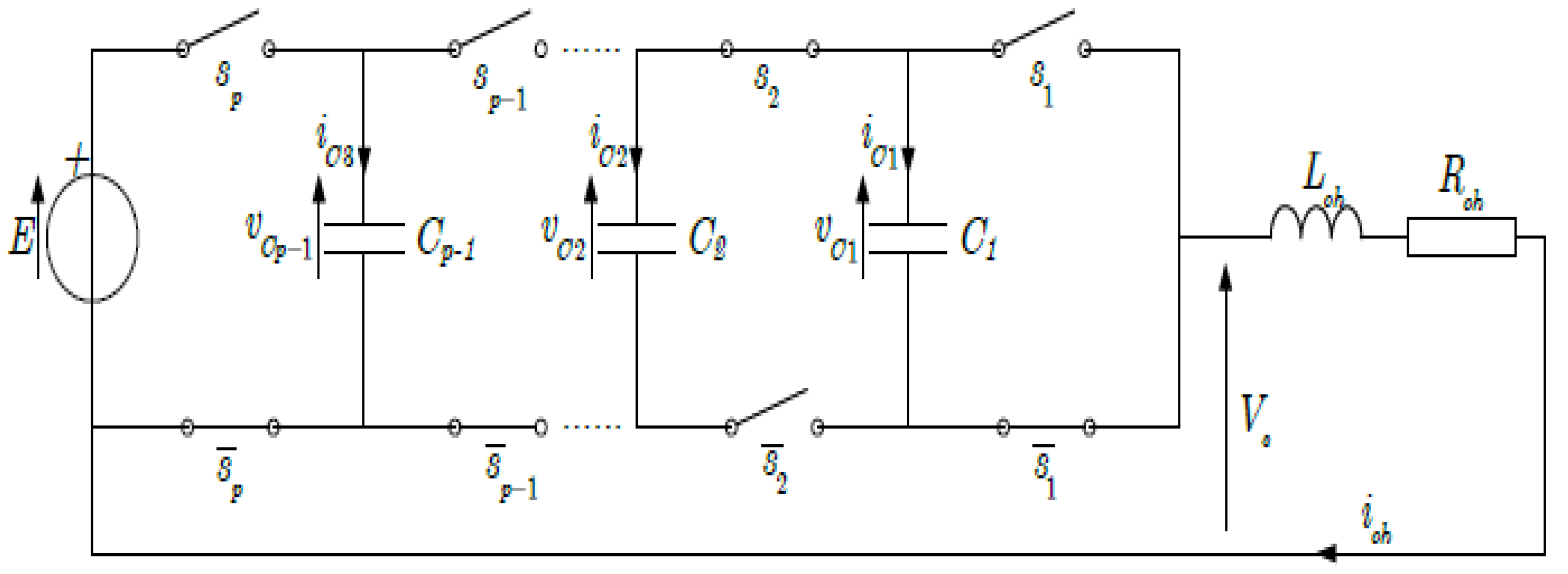
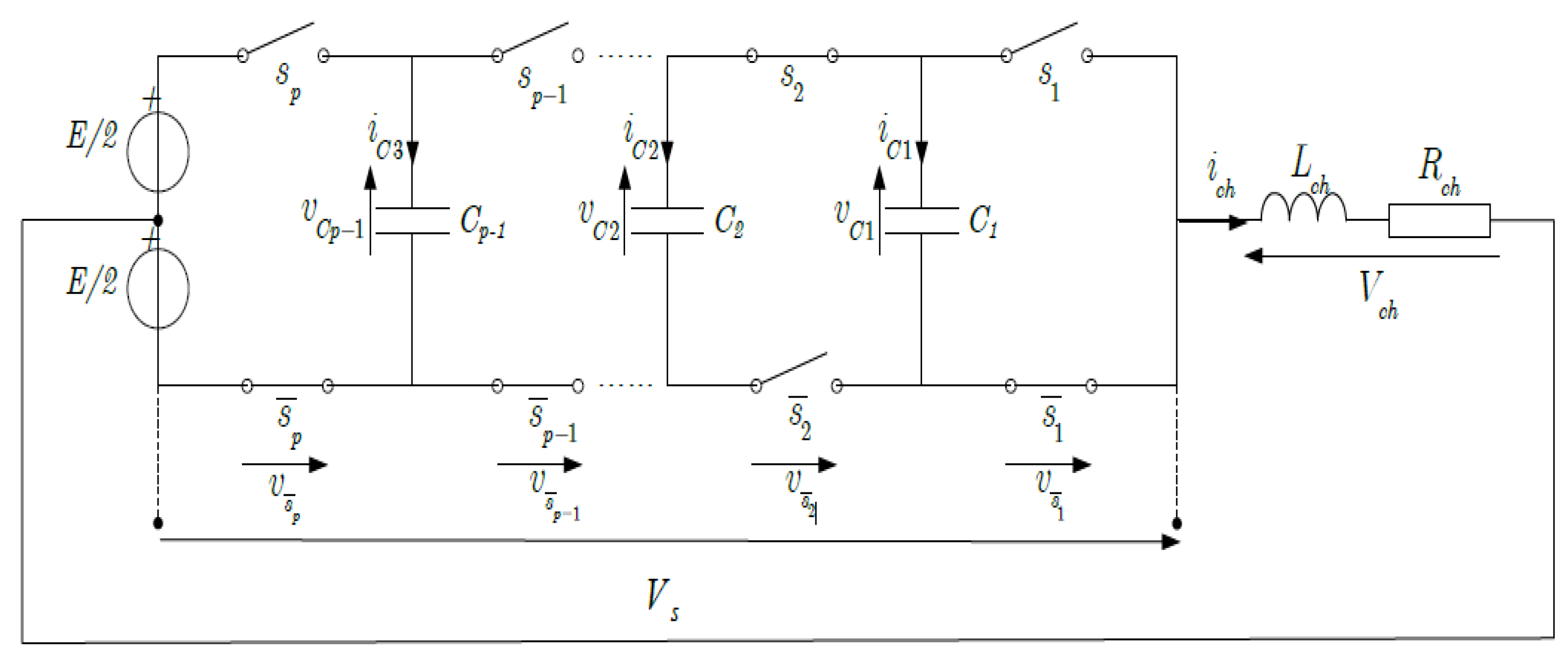
The following figure represents a multi-cell converter with p cells connected in series to an R-L load [17].
To model this system, we need to implement:
p-1 equations related to the evolution of the voltages across the p-1 floating capacitors;
An equation related to the load current, ich.
Figure 2.
P-cell chopper associated with an R-L load.
Cell voltages can be expressed as a function of capacitor voltages, as follows:
With and .
The capacitor voltages can be written as a function of the output current and the states of the adjacent switches:
So:
Such that ici represents the current passing through the capacitor Ci.
The output voltage Vs corresponds to the sum of the voltages across the switches. These voltages are defined by:
Knowing that:
So:
In the case of an R-L type load, the equation giving the evolution of the current ich is obtained from the voltage Vch.
From where:
Using Equation (14) we obtain the expression for the evolution of the current ich on as a function of the voltages of the floating capacitors :
In general, the instantaneous model of a multi-cell converter operating as a chopper-buck converter is given by the following set of equations:
To easily find the state representation of the system, we set:
So, Equation (17) becomes:
From (18) we find the state representation of the system as follows:
Such as:
2.4. Inverter Model
A series R-L circuit powered with a mid-point source, as shown in Figure 8, produces positive and negative output voltages.
The voltage across the load terminal is therefore written as follows:
This implies that the expression for the load current becomes:
So, the general expression for the evolution of the charging current ich is written in the form:
We can therefore represent the system, when operating as an inverter, by a set of equations identical to those of the chopper, with the only difference being the expression for the load current:
After formulating the instantaneous model of the multi-cell converter for both chopper and inverter operation, we now turn to the simulation and control of its switching devices.
2.5. Switch Control
As previously described, the switches in the different cells are controlled by the signals Si, which are set to 0 when the switches are blocked and to 1 when they are conducting. These signals can be obtained using pulse-width modulation (PWM), in which the intersections between a reference (modulating) wave and a generally triangular carrier wave determine the switching. The control signals are generated directly from these intersections [19].
When controlling the switches of a multi-cell arm, the control signals must have identical duty cycles and a phase shift of corresponding to the phase between two signals controlling two adjacent cells. Obtaining these signals Si is possible by developing p triangular signals of frequency fp (corresponding to the switching frequency fdec) and phase-shifted by .
The modulation control signal (chopper operation) and the carrier functions are represented as follows:
Figure 4.
Control signals by modulation—chopper operation.
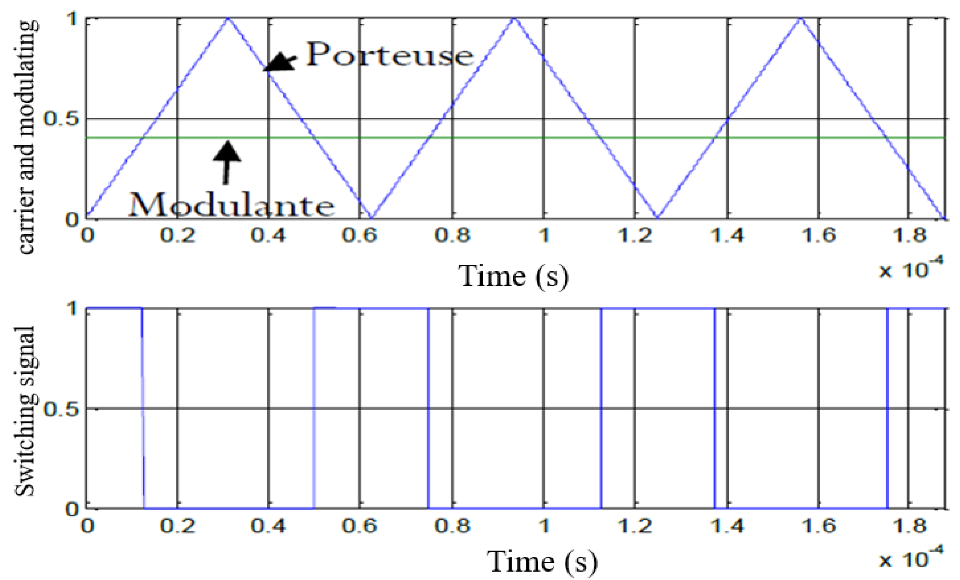
The carrier functions are given by:
For inverter operation, the modulation control signals are given by Figure 5:
The carrier functions are given by:
Comparing the Porti signals and the modulating modi will allow us to find the command Si signals as follows:
If
Otherwise then:
2.6. Closed-Loop Control of a Multi-Cell Arm
We have already seen in previous studies the open loop control (natural balancing) of a multicellular arm as well as its simulation which gave us a general idea of the operation of the multicellular, in what follows and to improve the performances and the results we will apply the closed loop control which consists of giving the reference signal from the signal resulting from the control [20].
2.6.1. Closed Loop Control Without Current Regulation
Firstly, a proportional control law that regulates only capacitor voltages is based on duty-cycle modulation. The principle of this first method is to modify these duty cycles [21].
If the duty cycles of cells and are different, the average current in capacitor Ci is not zero and consequently, the voltage changes.
When an imbalance appears on a capacitor voltage , the average current that crosses the capacitor during a switching period is such that the voltage tends towards its equilibrium value. The relation then obtains the variation of the capacitor voltage :
So:
So, the command in the imbalance is expressed in the form:
It should be noted that there are p control quantities (p duty cycles) and p-1 capacitor voltages to be controlled. This implies that the additional control variable will either be held constant at the operating point or used to control an output quantity of the converter. Our primary concern is controlling the voltages ; the input quantity is constant, and we have arbitrarily chosen the duty cycle .
We have:
By choosing the duty cycle to be up, we can easily reconstruct the (p-1) duty cycles.
The following figure generally represents the control law of p cells.
Figure 6.
Structure of the control law modulating the duty cycles [32].
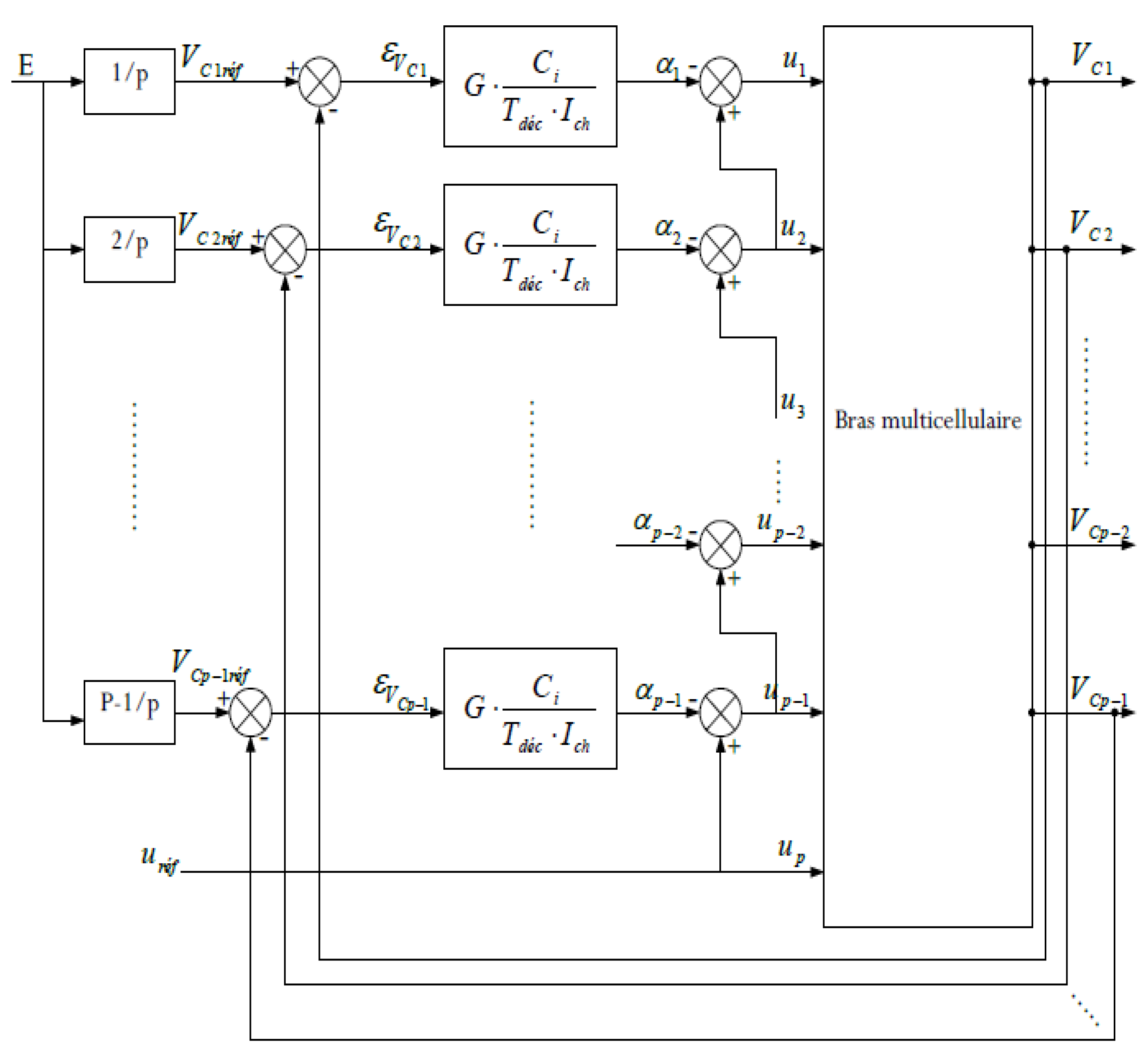
The control law is given by the equations:
Such that i varies between 1 and p-1.
The difference corresponds to the error ; we see that when this difference is zero, all the cyclic ratios are equal.
Since the current can be represented by its average over a switching period, it is possible to define, in the frequency domain, a control loop specific to each capacitor.
Figure 7.
VCi floating voltage regulation loop [32].
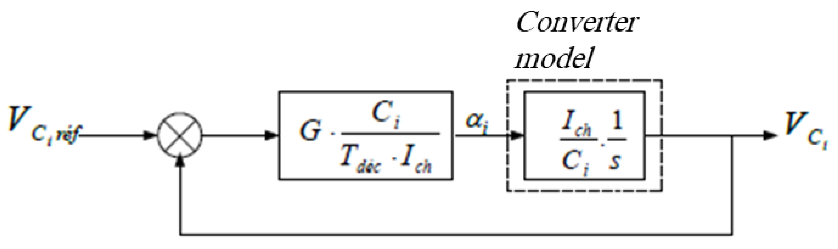
The transfer function governing this system is:
Is a first-order transfer function such that .
The choice of gain G is made by considering the following points:
The higher the capacitor Ci and the gain G, and the lower the current Ich, the faster the regulation will saturate;
With the power source set to its reference value E, the converter is started (with the capacitors Ci discharged) with a duty cycle defining the operating point (load current).
In the initial state the error is maximum:
The reference duty cycle uref allows the rest of the duty cycles to be calculated using the recurrence equation given by (30).
According to these recurrence equations, we notice that each ratio is less than its predecessor, such that:
The gain is therefore calculated as and that So:
We then deduce that the time constant which characterizes the system is expressed in the form:
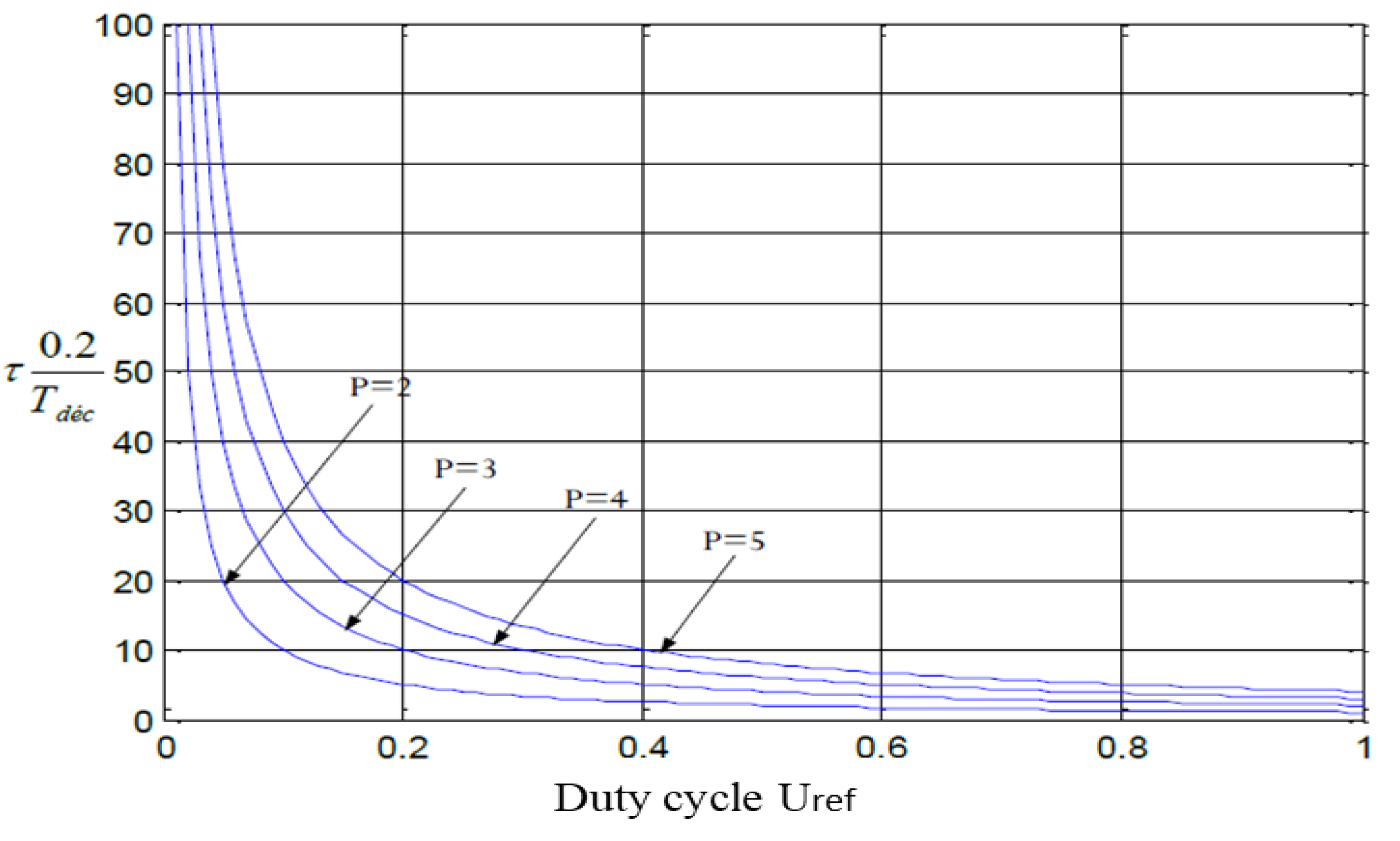
It is then possible to define a relationship between the time constant and the switching period Tdéc, as well as the duty cycle uréf. For this, we consider that the capacitor Ci is sized according to the maximum voltage ripple at its terminals:
Substituting the expression in Equation (36) and assuming that the ripple D1 is set at 10% of E/p (E/p corresponds to the equilibrium value of the switching voltages), the time constant becomes:
The evolution of the time constant in reduced units is shown in Figure 8 and indicates that it decreases as the duty cycle increases.
Figure 8.
Evolution in the reduced unit of the time constant as a function of the reference duty cycle and number of cells p.
Figure 8.
Evolution in the reduced unit of the time constant as a function of the reference duty cycle and number of cells p.
As regards the charging current Ich, since it is not regulated, it is directly subject to variations in the supply voltage because the continuous value, as its continuous value depends on it:
in the case of a step-down chopper.
2.6.2. Decoupling Control
To facilitate comparison with direct predictive control, we implemented a decoupling control, which enables control of floating voltages and effective current monitoring using a PI-type corrector. This approach uses a classic control principle for multi-cell inverters, specifically employing phase-shifted PWM among the switching cells, where denotes the frequency and p is the number of cells [22].
The control of the floating voltages remains the same; the only difference is that we will calculate the reference duty cycle from the current control loop, whose parameters are computed as follows:
The transfer function of the open-loop system:
Hence, the control is as follows:
Figure 9.
Decoupling control.
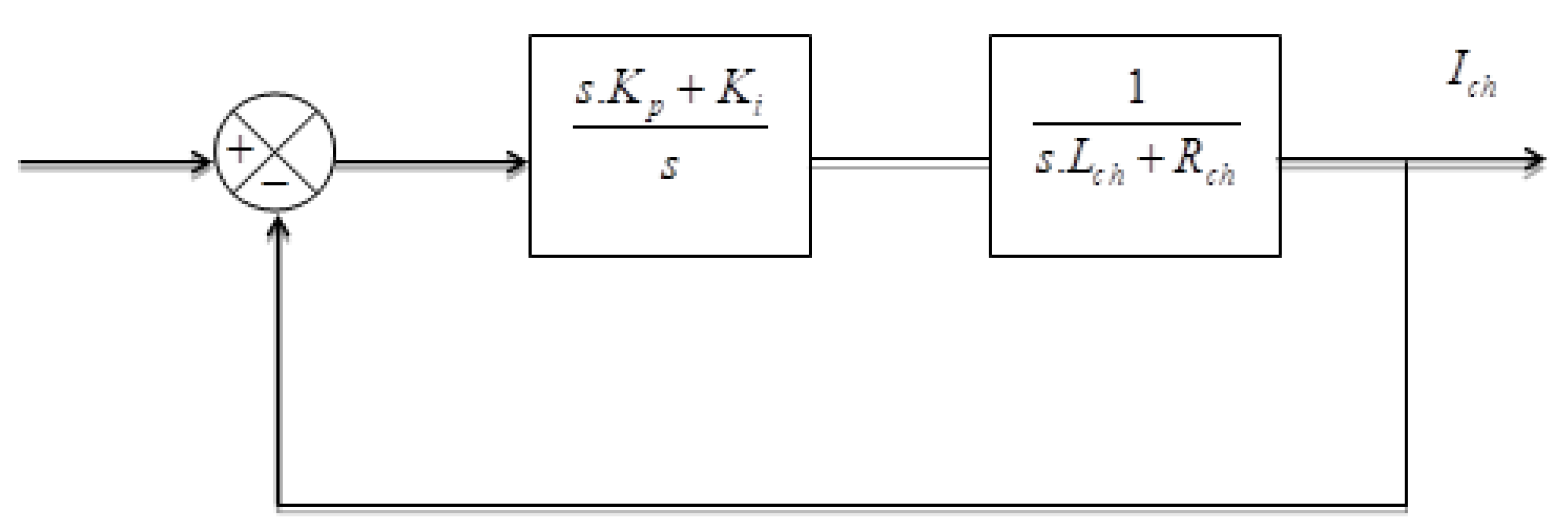
So, the transfer function of the closed loop system is:
The PI controller parameters are calculated using the pole-placement method.
The choice of the values of the natural pulsation and the damping coefficient is made as follows:
Such that represents the response time of the system.
2.6.3. Sliding Mode Control of the Multi-Cell Converter
Sliding mode control is a suitable control solution for a switching converter. In this section, we propose a sliding-mode controller for the multi-cell converter under study. Sliding mode control is a nonlinear control technique based on Variable Structure Theory. It is straightforward to complete and provides insight into the robustness of the controlled system and its dynamic response. For the proposed sliding mode control, the sliding surface is defined as follows [23]:
The Si components are defined as follows:
Our goal is to control the sliding surface, such as:
Where is the voltage of the kth floating capacitor, and is the reference defined by the following equation:
With: ich is the load current, and iref is its desired reference.
The control signal is defined by:
With: This control mode allows the convergence of V and I towards their reference values [30].
3. Simulations and Results
3.1. The Simulation of a Closed-Loop Controlled Multi-Cell Arm Without the Current Regulation
The simulation of a closed-loop-controlled multi-cell arm without regulation of the Ichse load current is performed with the following parameters:
The results illustrated in Figure 10 demonstrate the ability of the proposed control strategy to ensure effective voltage regulation of the floating capacitor under steady-state and dynamic operating conditions. The rapid convergence of the capacitor voltage toward its reference value, with negligible steady-state error, highlights the intrinsic balancing capability of the converter when properly controlled. This behavior confirms that the energy exchanged between the switching cells is correctly managed, despite the nonlinear and hybrid nature of the multicellular converter. Moreover, the absence of large oscillations indicates that the controller maintains a satisfactory damping of the internal energy dynamics, which is a critical requirement for ensuring long-term reliability and preventing overvoltage stress on semiconductor devices:
Figure 11 further emphasizes the robustness of the control scheme by illustrating the system response under transient conditions, such as load or reference variations. The smooth evolution of the electrical quantities reflects a well-coordinated interaction between the converter stages, avoiding excessive circulating currents or abrupt voltage deviations. From a converter design standpoint, this behavior is particularly significant, as it demonstrates that the proposed approach limits internal energy imbalance while preserving fast dynamic response. Such a compromise between dynamic performance and internal stability is often difficult to achieve in multilevel and multicellular topologies, where strong coupling effects may otherwise degrade system performance:
Figure 12 shows that the switching cell voltages converge to 500 V, with a rapid dynamic response and near-zero static error. This voltage represents one-third of the source voltage (E/3), demonstrating the effectiveness of the control.
The waveforms presented in Figure 12 provide additional insight into the quality of the power conversion process. The reduced ripple and well-shaped voltage and current profiles confirm that the converter operates close to its ideal switching behavior. This reflects an efficient modulation strategy and an adequate control bandwidth, ensuring that the converter meets power quality requirements while minimizing switching losses. From a broader perspective, these results validate the suitability of the proposed converter–control association for high-performance energy conversion applications, where efficiency, robustness, and voltage balancing are key challenges. Collectively, the three figures confirm that the proposed approach offers a coherent and reliable solution for advanced static power conversion systems, particularly in applications involving renewable energy integration and high-power electronic interfaces.
3.2. Simulation Result of the Decoupling Control
The simulation model using the MATLAB program is illustrated in the following figure.
Figure 3.
Inverter p cells with capacitive midpoint associated with an R-L load.
The simulations of the decoupling control are carried out with the following parameters:
The response to a 1500V voltage step, followed by a sudden drop to 1000V, demonstrating the operation of the control, is shown in the following figures.
Figure 14 and Figure 15 show that the floating capacitor voltages balance and follow their references and their dynamics are fast, such that the capacitor of cell 1 balances at the value 500V which is equal to E/3, and the voltage of capacitor two balances at the value 1000V which represents 2/3 of the source voltage (2E/3), then at the time of the voltage drop to 1000V the capacitor voltages quickly follow their references. Hence, the control ensures perfect balancing.
The results depicted in Figure 14 highlight the dynamic behavior of the converter under controlled operation, revealing a clear improvement in stability and regulation performance compared to conventional strategies. The controlled variables exhibit smooth trajectories with limited overshoot and fast settling time, which indicates that the control scheme efficiently manages the internal energy exchanges within the converter. This response confirms that the proposed approach successfully mitigates the strong coupling effects inherent to multicellular and multilevel static converters, ensuring a predictable and well-damped dynamic behavior even in the presence of nonlinearities and switching phenomena.
Figure 15 provides further insight into the robustness of the converter when subjected to operating condition variations, such as changes in load or reference values. The observed waveforms demonstrate that the converter maintains satisfactory performance without inducing excessive oscillations or instability. From a power electronics standpoint, this behavior is particularly relevant, as it reflects the controller’s ability to preserve voltage and current balance while avoiding harmful transient stresses on semiconductor devices and passive components. Such robustness is a key requirement for practical deployment in high-power and renewable energy applications, where operating conditions are inherently variable and uncertain.
Figure 16 shows that the load current closely follows its reference value and exhibits a rapid dynamic response, indicating that the regulation performs very effectively.
The results illustrated in Figure 16 emphasize the effectiveness of the proposed control strategy in ensuring stable and well-regulated operation of the static converter under nominal conditions. The smooth and well-damped evolution of the electrical variables reflects a precise management of the converter’s internal energy dynamics. This behavior confirms that the control scheme successfully handles the nonlinear and switched nature of the system, maintaining internal voltage balance while avoiding excessive transient stresses. Such performance is particularly important in multicell and multilevel converters, where improper energy distribution can lead to instability or premature component degradation.
Figure 17 shows that the voltages at the switch terminals (cell voltages) all converge to 500 V with a rapid dynamic response. We therefore conclude that the PI control is effective. This figure provides further evidence of the robustness of the converter when operating conditions vary. The system demonstrates a fast recovery and limited overshoot in response to disturbances, indicating a strong resilience to parameter variations and external perturbations. From a power electronics standpoint, this response highlights the controller’s capability to mitigate coupling effects between converter stages and to suppress internal circulating currents. This robustness is a key requirement for practical implementations, especially in high-power and renewable energy applications, where fluctuations in load and source conditions are unavoidable.
3.3. Simulation Result of the Sliding Mode Control
To illustrate the proposed control, we consider a multi-cell circuit with three cells connected to an R-L load. The control law aims to ensure that the sliding surfaces Si converge to zero, allowing the variables to reach their references.
We use the same parameter as in the previous control.
Figure 18 demonstrates that the objective of this control is met, as the voltage of capacitor C1 follows its reference with rapid dynamics and reduces disturbances, so that the floating voltage Vc1 converges to the desired reference of 500 V. This figure confirms the high quality of the power conversion achieved by the proposed approach. The reduced ripple content and well-shaped voltage and current profiles indicate an efficient modulation process combined with an adequately tuned control bandwidth. This results in improved power quality, reduced switching stress, and enhanced overall efficiency. Collectively, the behaviors observed in Figure 16 and Figure 17, and 18 demonstrate that the proposed converter–control association offers a coherent and reliable solution for advanced static power conversion systems, ensuring a favorable compromise between dynamic performance, robustness, and energy efficiency.
Figure 19 highlights that the purpose of this control is satisfied, as the voltage of capacitor C2 follows its reference with rapid dynamics, in addition to the reduction of disturbances, such that the floating voltage Vc2 converges towards the desired value of 1000 V. This figure clearly demonstrates that the control objective is fully achieved, as the voltage across capacitor C2 accurately tracks its reference with fast and well-damped dynamics. The control strategy effectively attenuates disturbances, ensuring a smooth transient response and a stable steady state. As a result, the floating capacitor voltage Vc2 converges reliably toward the desired reference value of 1000 V, confirming the robustness and efficiency of the proposed regulation scheme in maintaining voltage balance under dynamic operating conditions.
Figure 20 shows that the charging current Ich accurately tracks its reference with excellent precision, reflecting a fast and well-controlled dynamic response. The absence of steady-state error confirms the effectiveness of the control strategy in ensuring precise current regulation. Consequently, the charging current exhibits a clean sinusoidal behavior, oscillating symmetrically between +60 A and −60 A, which highlights the high dynamic performance and stability of the overall system.
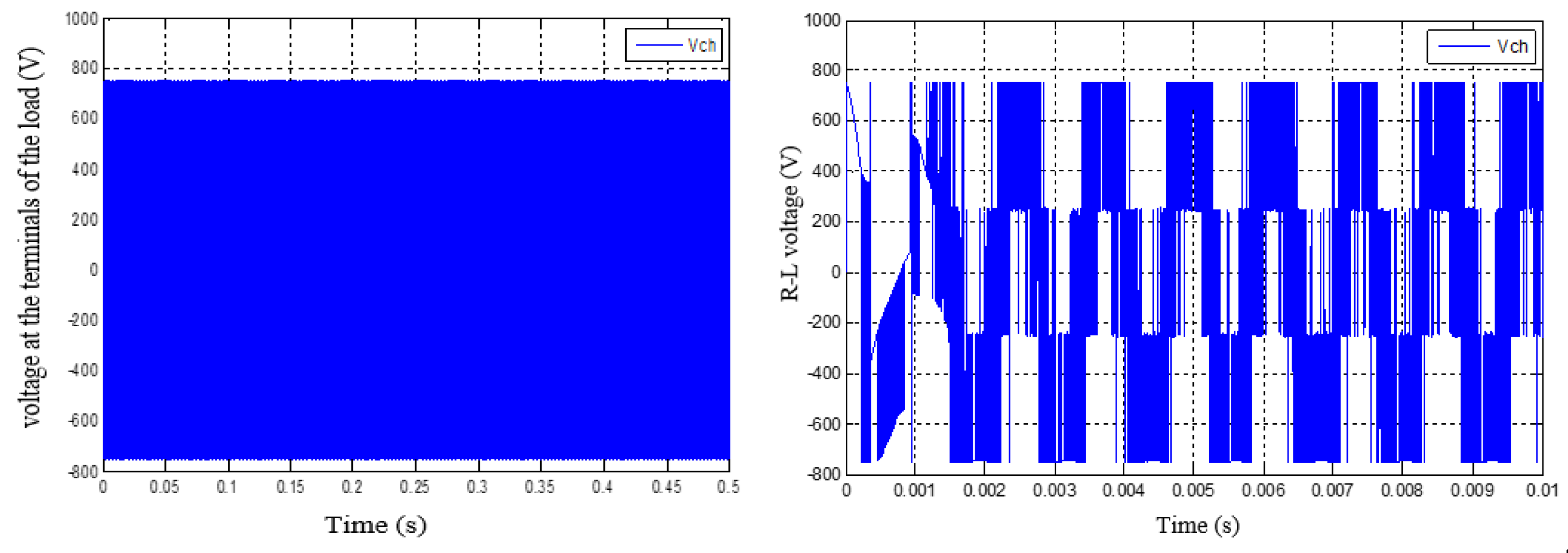
Figure 21 clearly illustrates that the voltage across the R–L load at the multicell inverter output exhibits a well-defined alternating waveform, rapidly varying between −800 V and +800 V. This fast and stable voltage transition confirms the effectiveness of the sliding mode control strategy in driving the multicell inverter. The obtained results demonstrate that the controller operates as intended, ensuring robust performance, high dynamic response, and reliable voltage synthesis at the inverter output.
4. Conclusions
This paper presents a thorough investigation of the topology, modeling, and advanced control strategies for multicellular converters operating in both chopper and inverter modes. It provides a detailed theoretical framework and comprehensive mathematical models, including both instantaneous and averaged representations, describing the behavior of series multicellular converters. Building on this foundation, several control strategies were developed and analyzed, including open-loop natural balancing, closed-loop PI regulation, decoupling control, and sliding mode control. Simulation results demonstrate that the proposed approaches effectively achieve voltage balancing across floating capacitors, enhance dynamic performance, and significantly reduce voltage and current fluctuations. Notably, the closed-loop PI and decoupling controllers ensure precise regulation under both steady-state and transient conditions, while the sliding mode control offers strong robustness, rapid tracking, and minimal steady-state error, making it particularly suitable for applications requiring fast response and effective disturbance rejection. These findings highlight that advanced control strategies can substantially improve the performance, stability, and efficiency of multicellular converter systems, which is critical for high-power, high-reliability applications such as renewable energy conversion. Future work will focus on the practical implementation of a three-arm multicellular inverter in a wind turbine conversion chain to mitigate control chattering and validate the proposed methods under real-world operating conditions. Such developments represent a crucial step toward more efficient, reliable, and compact power conversion solutions for modern energy systems.
References
- Blaabjerg, F.; Yang, Y.; Kim, K.A.; Rodriguez, J. Power Electronics Technology for Large-Scale Renewable Energy Generation. Proceedings of the IEEE 2023, vol. 111(no. 4), 335–355. [Google Scholar] [CrossRef]
- Zhongting, T.; Yongheng, Y.; Frede, B. Power electronics-the enabling technology for renewable energy integration. CSEE Journal of Power and Energy Systems 2021, vol. 8(no. 1). [Google Scholar] [CrossRef]
- Gonzatti, R.B.; Li, Y.; Amirabadi, M.; Lehman, B.; Peng, F.Z. An Overview of Converter Topologies and Their Derivations and Interrelationships. IEEE J Emerg Sel Top Power Electron 2022, vol. 10(no. 6), 6417–6429. [Google Scholar] [CrossRef]
- Toubakh, H.; Sayed-Mouchaweh, M.; Benmiloud, M.; Defoort, M.; Djemai, M. Self-adaptive learning scheme for early diagnosis of simple and multiple switch faults in multicellular power converters. ISA Trans 2021, vol. 113, 222–231. [Google Scholar] [CrossRef] [PubMed]
- Hamdi, R.; Hamida, A.H.; Bennis, O. On modeling and real-time simulation of a robust adaptive controller applied to a multicellular power converter. Electrical Engineering & Electromechanics 2022, no. 6, 48–52. [Google Scholar] [CrossRef]
- Benmiloud, M.; Benalia, A. Hybrid control scheme for multicellular converter. in 2013 International Conference on Control, Decision and Information Technologies (CoDIT), May 2013; IEEE: Hammamet, Tunisia; pp. 476–482. [Google Scholar] [CrossRef]
- Said, S.B.; Saad, K.B.; Benrejeb, M. HIL simulation approach for a multicellular converter controlled by sliding mode. Int J Hydrogen Energy 2017, vol. 42(no. 17), 12790–12796. [Google Scholar] [CrossRef]
- DJEMAI, M.; BUSAWON, K.; BENMANSOUR, K.; MAROUF, A. Real time control via a high order sliding mode controller of a multi-cellular converter. IFAC Proceedings Volumes 2009, vol. 42(no. 17), 346–351. [Google Scholar] [CrossRef]
- Bouhafs, A.; Kafi, M.R.; Louazene, L.; Rouabah, B.; Toubakh, H. Fault-Detection-Based Machine Learning Approach to Multicellular Converters Used in Photovoltaic Systems. Machines 2022, vol. 10(no. 11), 992. [Google Scholar] [CrossRef]
- Gevorkov, L.; Domínguez-García, J.L.; Romero, L.T.; Martínez, À.F. Modern MultiPort Converter Technologies: A Systematic Review. Applied Sciences 2023, vol. 13(no. 4), 2579. [Google Scholar] [CrossRef]
- Won, J.; Srdic, S.; Lukic, S.M. Optimized Multi-Carrier PWM Strategy and Topology Review for Multi-Cell Series-Parallel Medium-Voltage Rectifier. IEEE J Emerg Sel Top Power Electron 2022, vol. 10(no. 6), 6770–6783. [Google Scholar] [CrossRef]
- Zebboudj, A.H.; Boukhelif, R.; Doghmane, M.Z.; Akroum, H.; Springer. Topology Analysis of Multi-cellular Converters in a Wind Energy System; Cham., 2023; vol. 591, Network, pp. 614–628. [Google Scholar] [CrossRef]
- Hamida, M.L.; FEKIK, A.; DENOUN, H.; Ardjal, A.; Azar, A.T. Sliding mode controller for a single-phase six-level flying capacitor inverter—application for a standalone PV system. In in Power Electronics Converters and their Control for Renewable Energy Applications; Elsevier, 2023; pp. 301–325. [Google Scholar] [CrossRef]
- Ramírez, R.O.; Baier, C.R.; Villarroel, F.; Espinosa, E.; Arevalo, M.; Espinoza, J.R. Reduction of DC Capacitor Size in Three-Phase Input/Single-Phase Output Power Cells of Multi-Cell Converters through Resonant and Predictive Control: A Characterization of Its Impact on the Operating Region. Mathematics 2023, vol. 11(no. 14), 3038. [Google Scholar] [CrossRef]
- Won, J.; Srdic, S.; Lukic, S.M. Optimized Multi-Carrier PWM Strategy and Topology Review for Multi-Cell Series-Parallel Medium-Voltage Rectifier. IEEE J Emerg Sel Top Power Electron 2022, vol. 10(no. 6), 6770–6783. [Google Scholar] [CrossRef]
- Luo, S.; Qin, D.; Wu, H.; Wang, T.; Chen, J. Multi-Cell-to-Multi-Cell Battery Equalization in Series Battery Packs Based on Variable Duty Cycle. Energies (Basel) 2022, vol. 15(no. 9), 3263. [Google Scholar] [CrossRef]
- Haroun, R.; El Aroudi, A.; Mandal, K.; Zhang, G.; Li, Z.; Martínez-Salamero, L. Fast Single-Loop Voltage-Based MPPT Using Sliding-Mode Control for Switched-Inductor Multi-Cell Boost Converters. IEEE Transactions on Circuits and Systems I: Regular Papers 1–14, 2025. [CrossRef]
- Hu, K.; Peng, L. A Digital FIR-Type Generic Multicell Network Control for LCL -Filtered Grid- Connected Inverters. IEEE J Emerg Sel Top Power Electron 2024, vol. 12(no. 5), 4691–4702. [Google Scholar] [CrossRef]
- Srief, M.L.; Soltane, B.; Lokmane, N.A.; Malak, G. A complete control structure based backstepping controller design for stacked multi-cell multi-level SPWM VSC STATCOM. Energy Reports 2024, vol. 12, 687–698. [Google Scholar] [CrossRef]
- Zebboudj, A.H.; Boukhelif, R.; Doghmane, M.Z.; Akroum, H. Topology Analysis of Multi-cellular Converters in a Wind Energy System; 2023; pp. 614–628. [Google Scholar] [CrossRef]
- Alepuz, S. A Survey on Capacitor Voltage Control in Neutral-Point-Clamped Multilevel Converters. Electronics (Basel) 2022, vol. 11(no. 4), 527. [Google Scholar] [CrossRef]
- Gong, Z.; Liu, C.; Shang, L.; Lai, Q.; Terriche, Y. Power Decoupling Strategy for Voltage Modulated Direct Power Control of Voltage Source Inverters Connected to Weak Grids. IEEE Trans Sustain Energy 2023, vol. 14(no. 1), 152–167. [Google Scholar] [CrossRef]
- Gong, S. Sliding Mode Control-Based Decoupling Scheme for Quad-Active Bridge DC–DC Converter. IEEE J Emerg Sel Top Power Electron 2022, vol. 10(no. 1), 1153–1164. [Google Scholar] [CrossRef]
Figure 1.
Three-cell half-bridge multi-cell inverter.
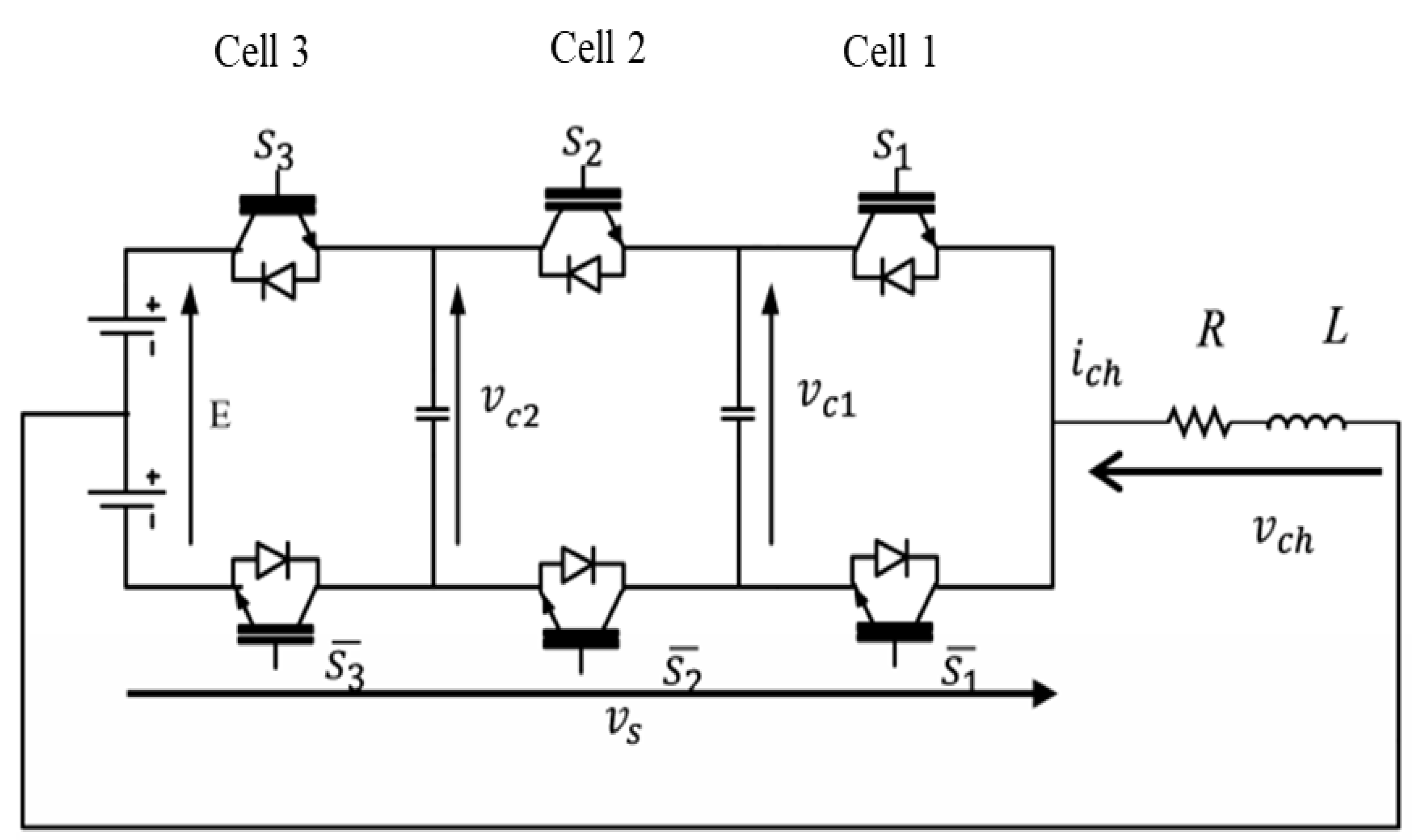
Figure 5.
Control signal by modulation—inverter operation.
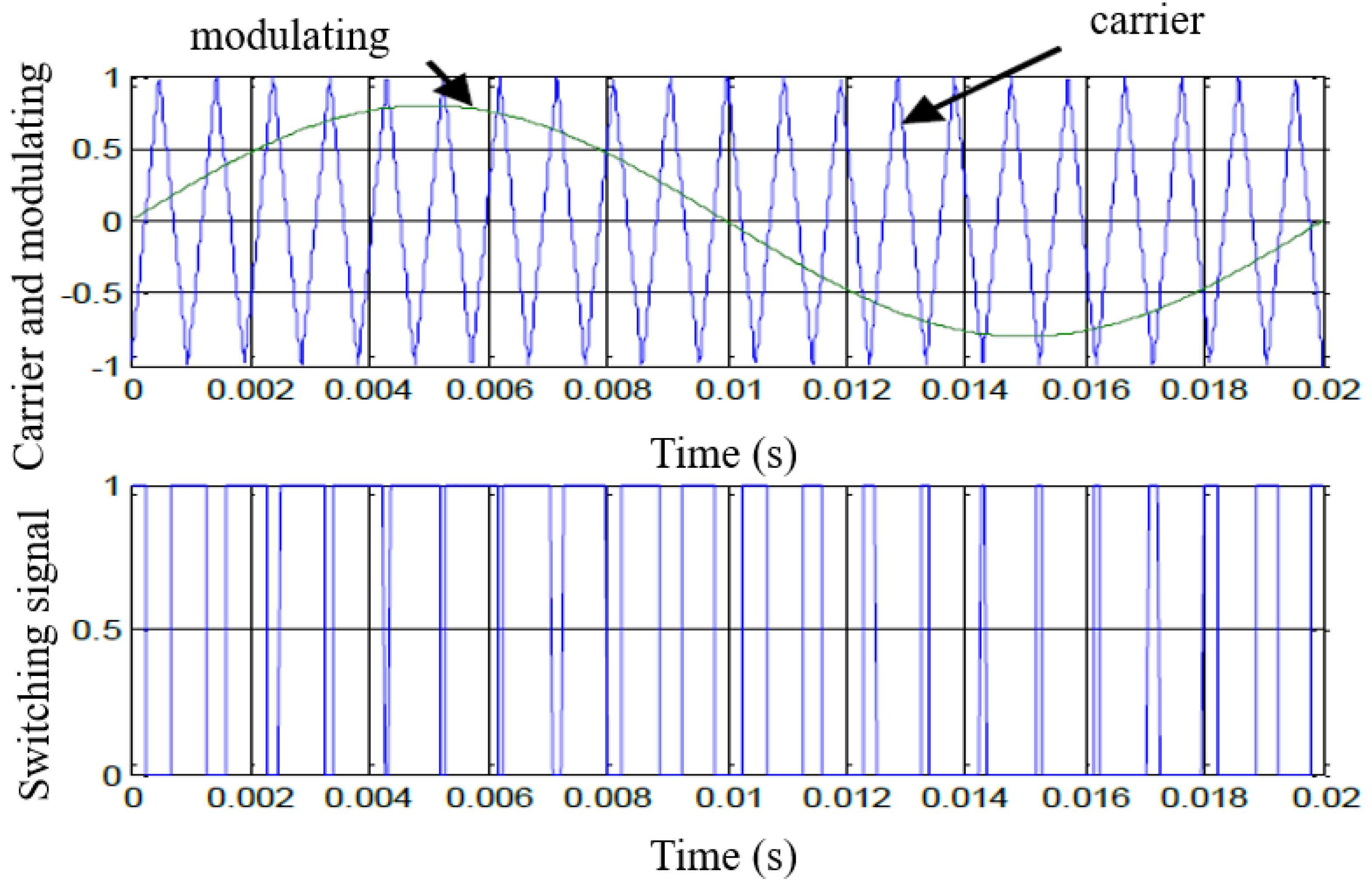
Figure 10.
Voltage across capacitor C1.
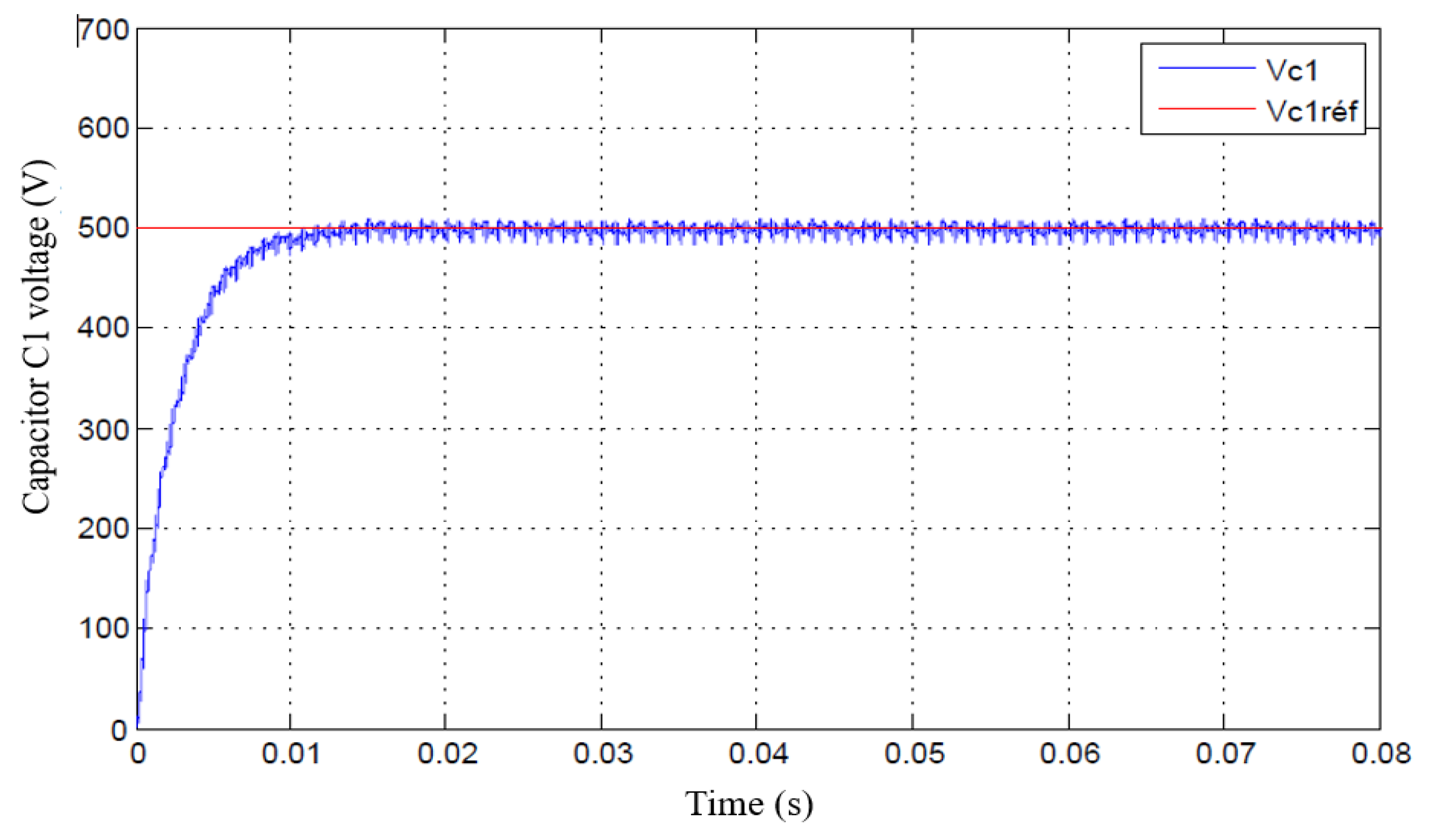
Figure 11.
Voltage across capacitor C2.
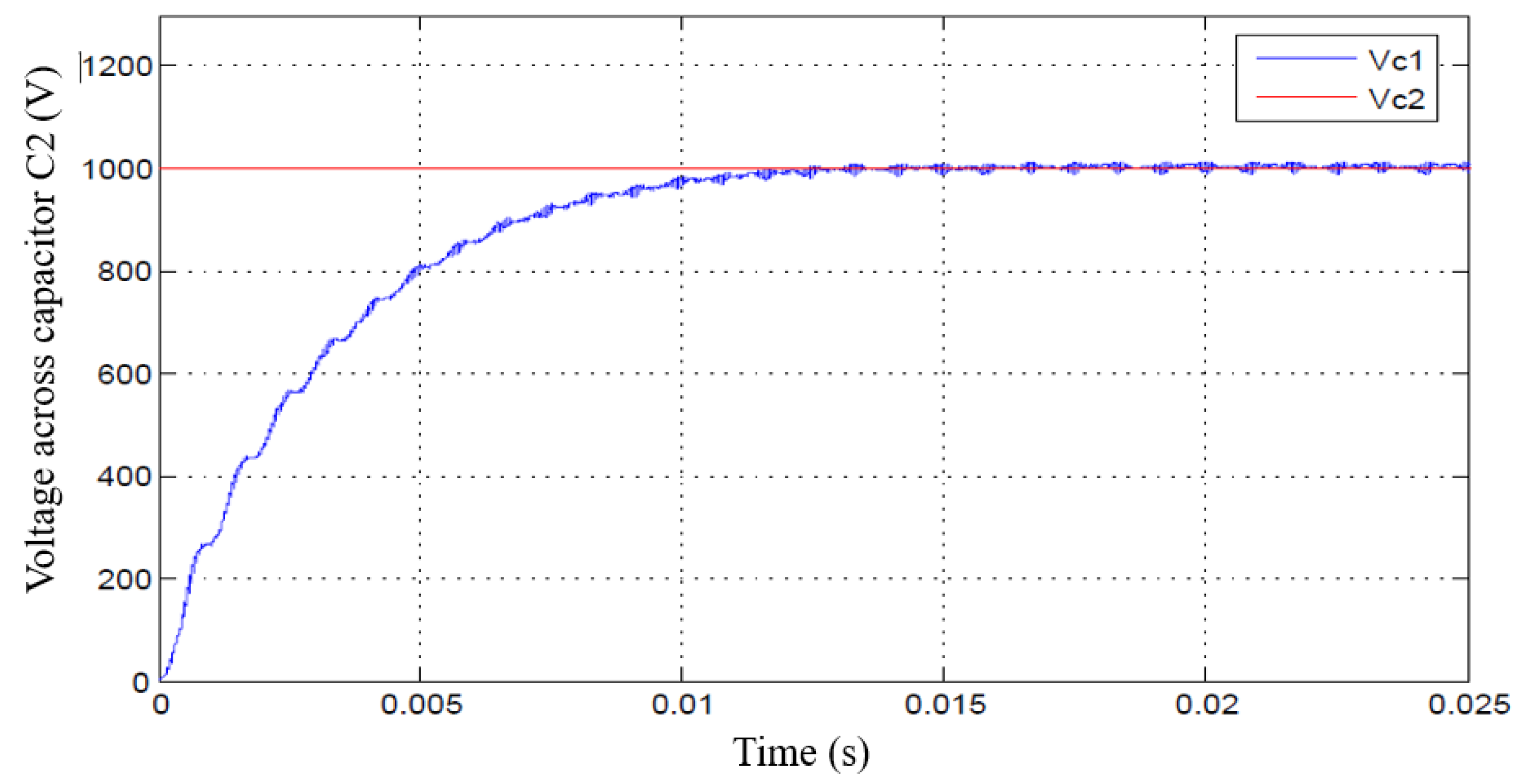
Figure 12.
Switching cell voltages.
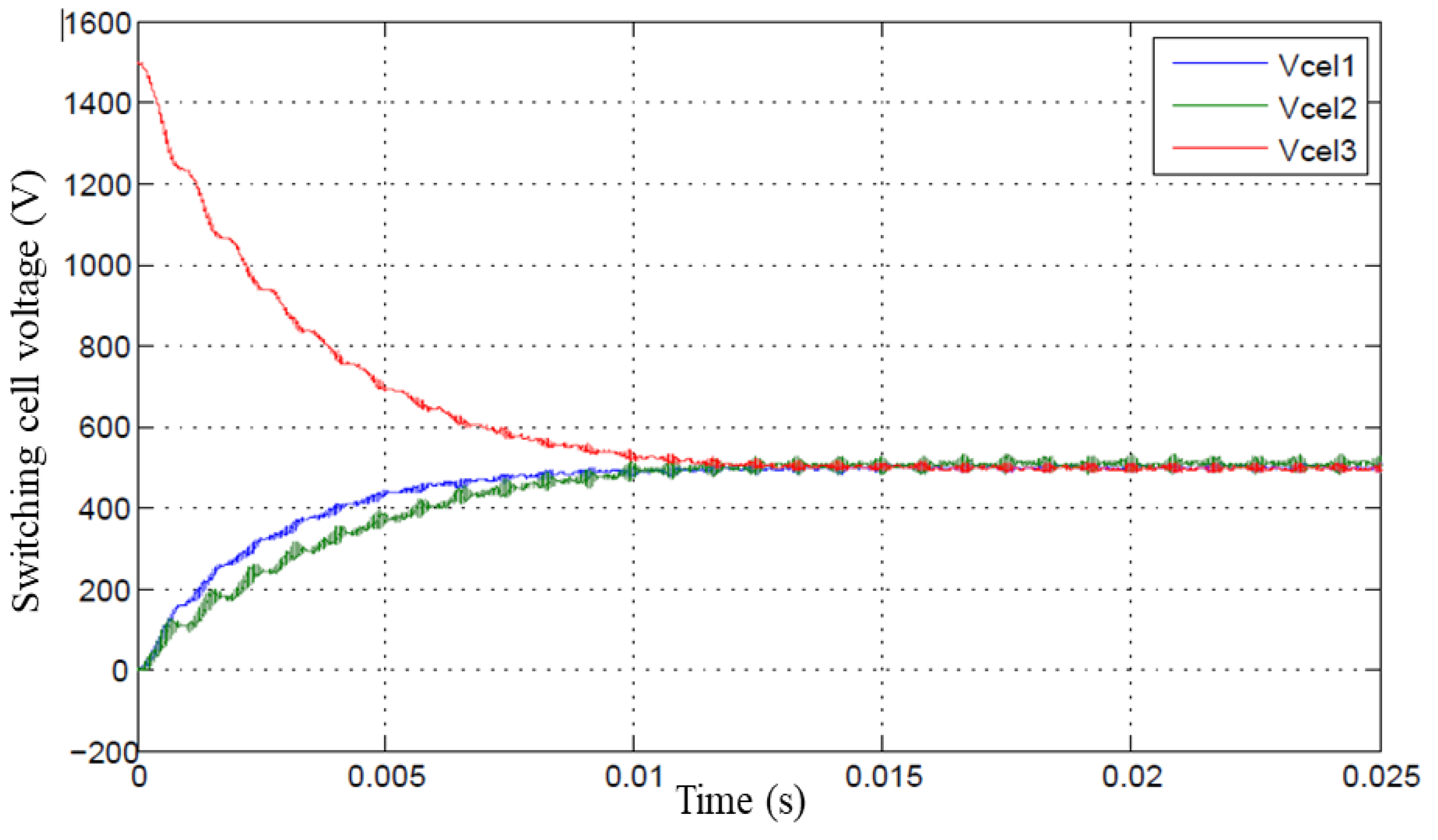
Figure 14.
The voltage across capacitor 1 and its reference.
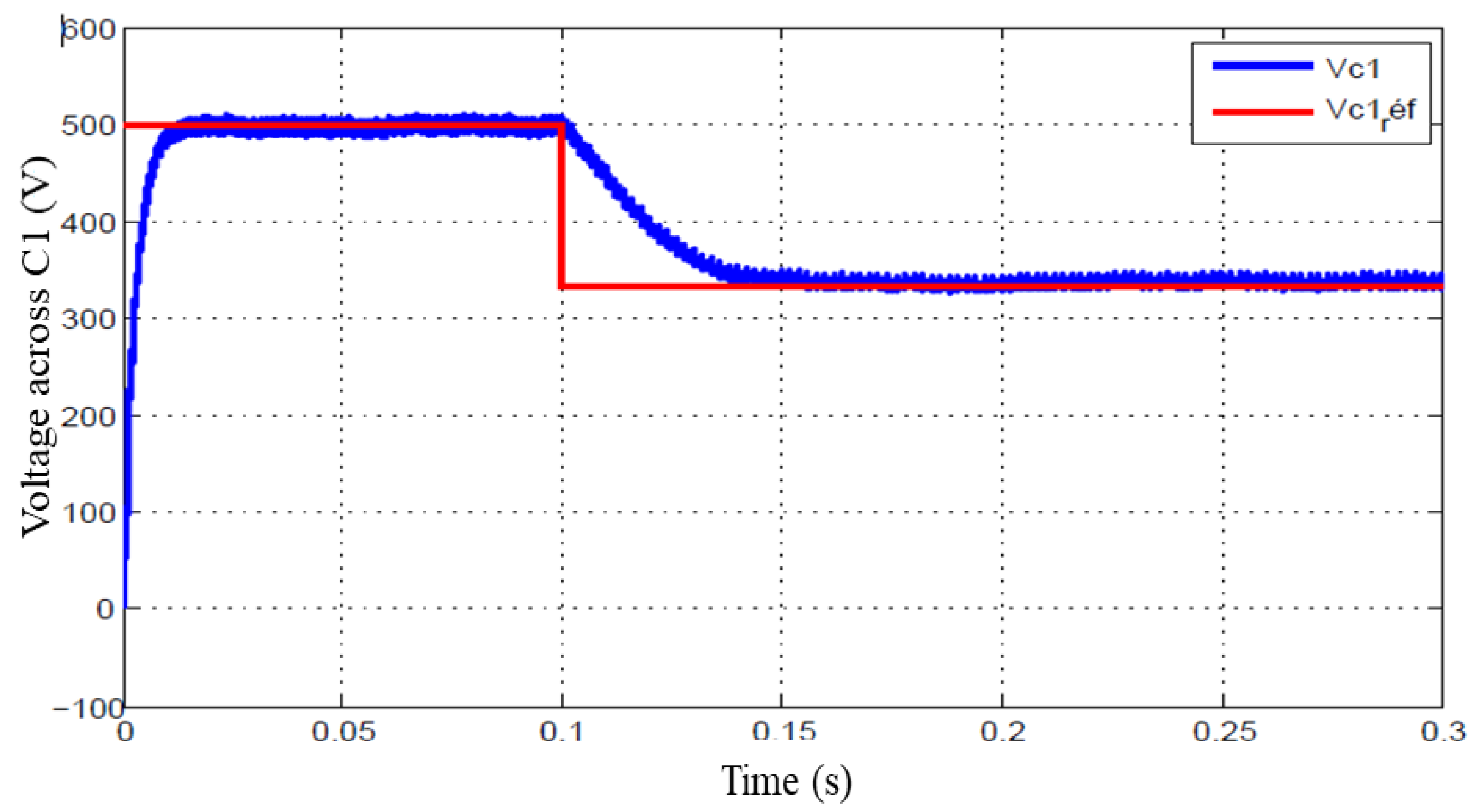
Figure 15.
The voltage across capacitor 2 and its reference.
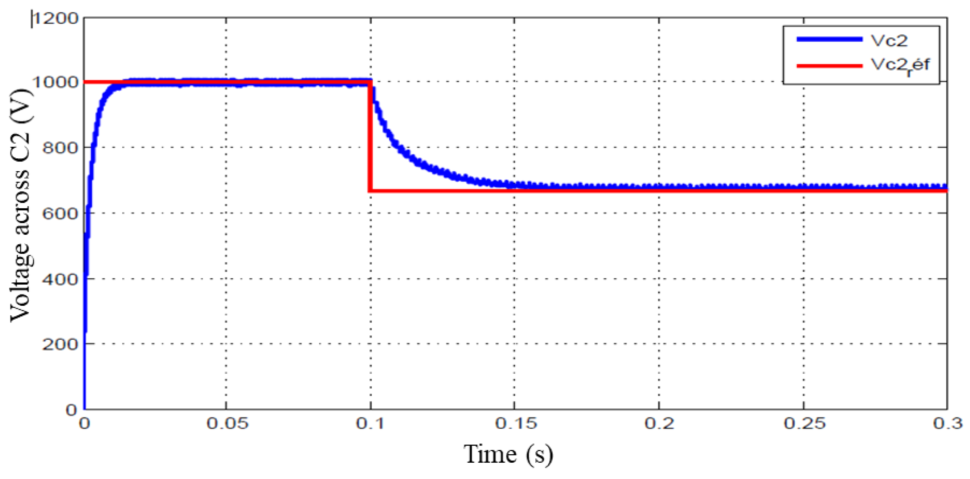
Figure 16.
This is a figure. Schemes follow the same formatting.
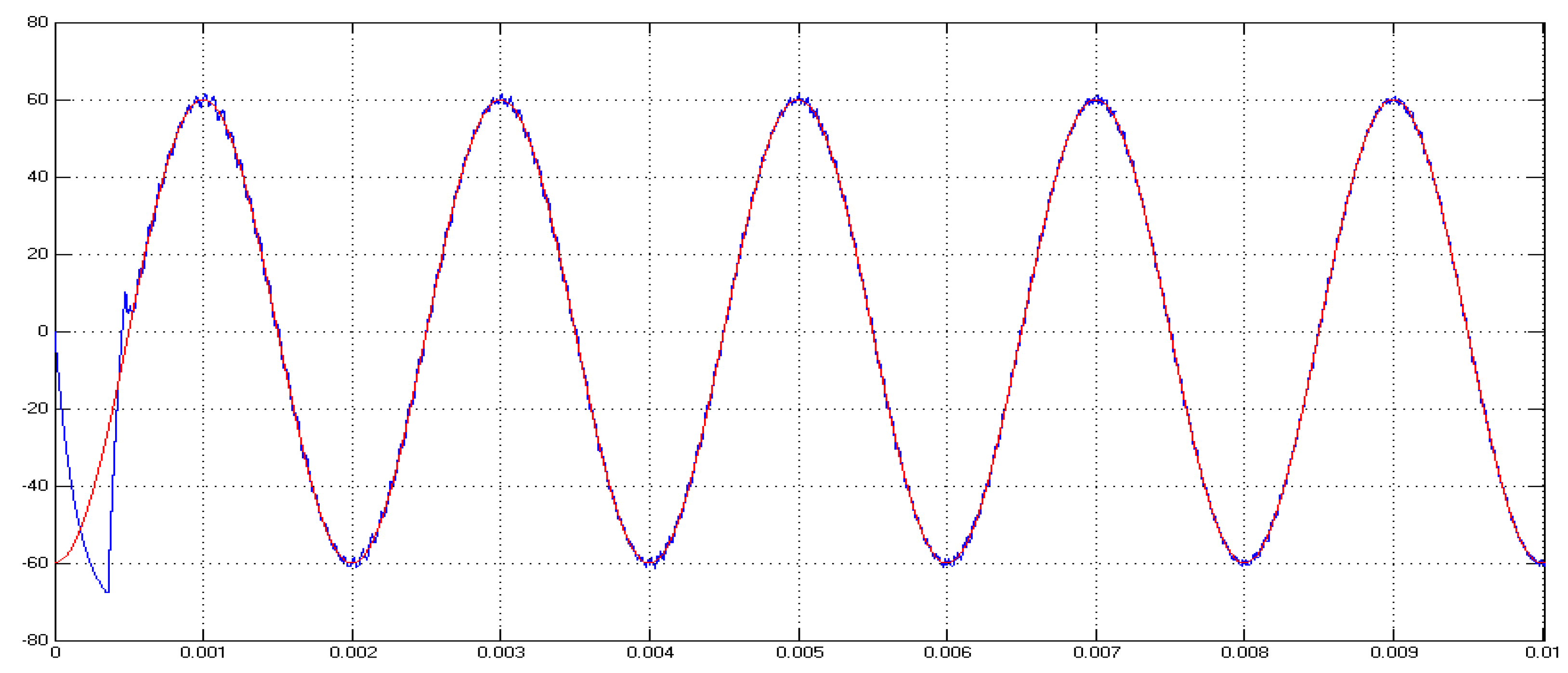
Figure 17.
Evolution of switching cell voltages.
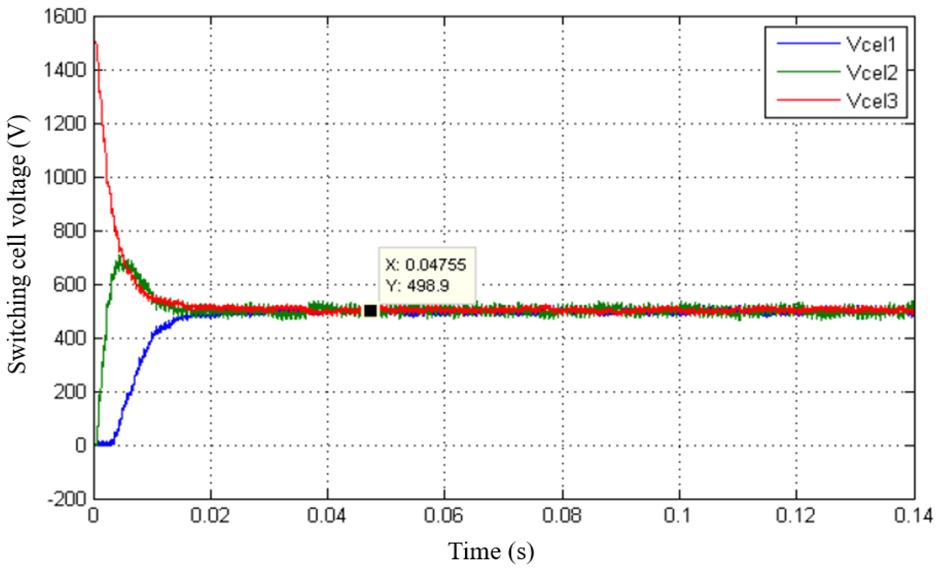
Figure 18.
Float voltage control C1.
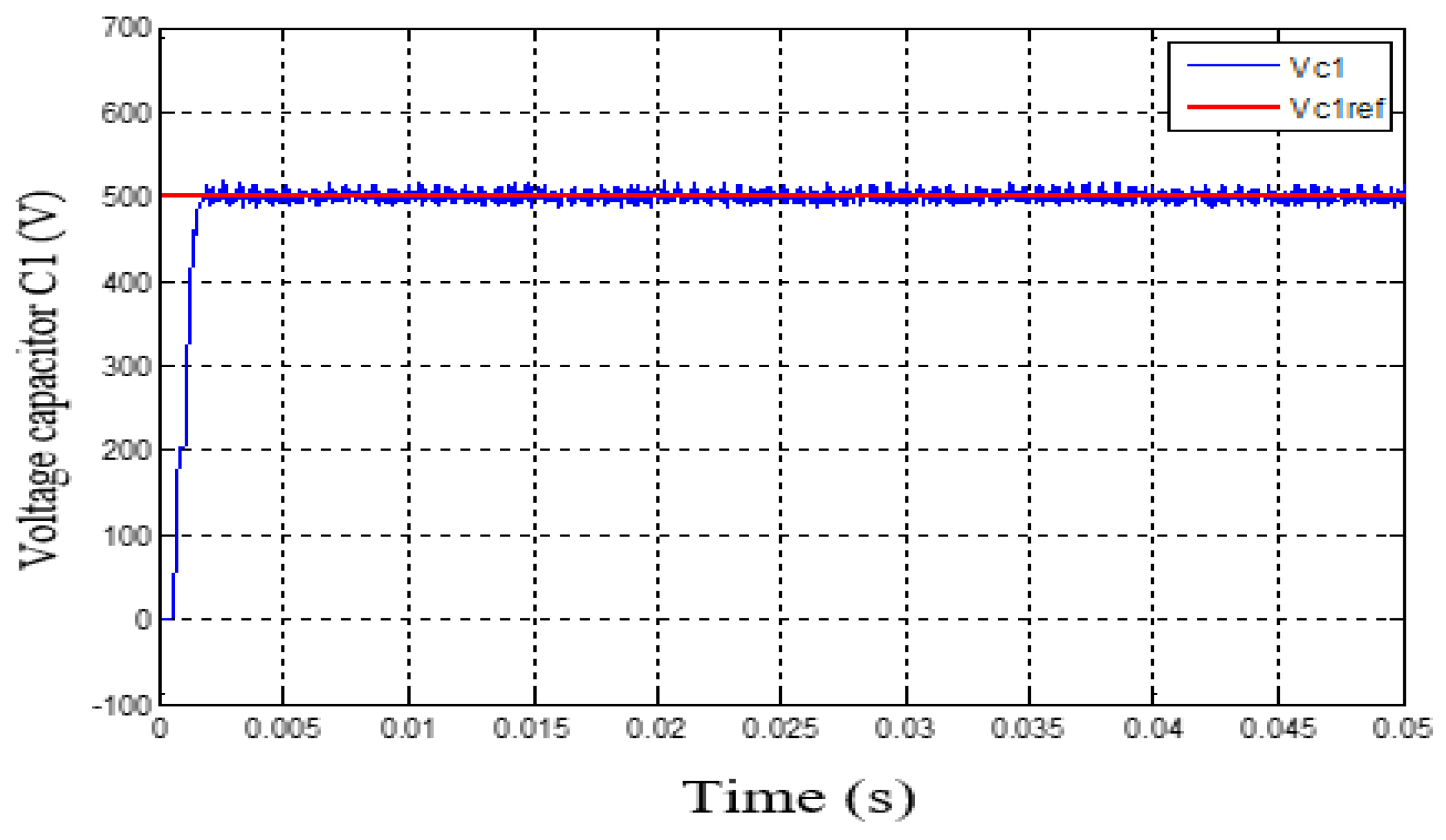
Figure 19.
Float voltage control C2.
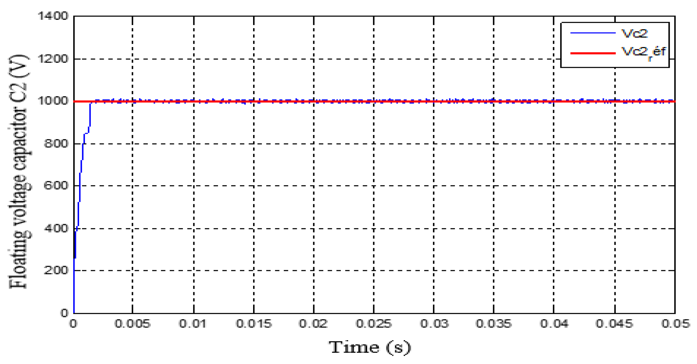
Figure 20.
Load current control.
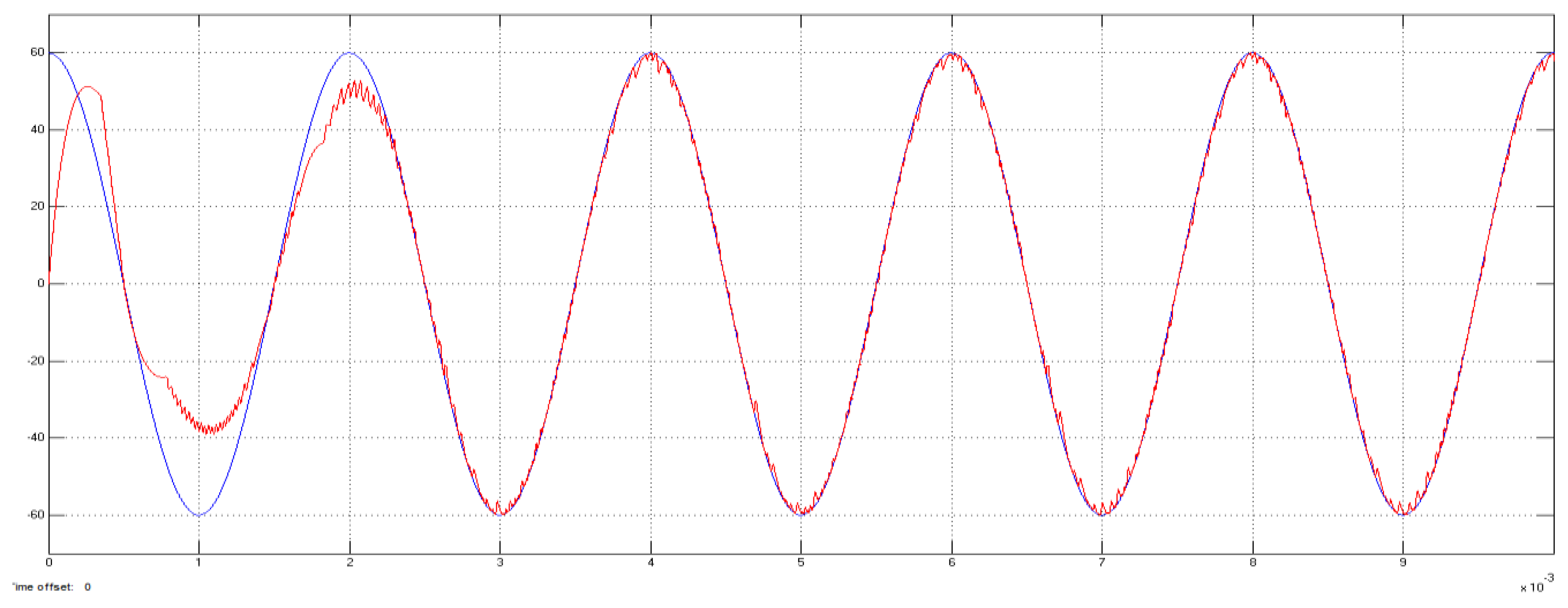
Figure 21.
Load voltage control.
Disclaimer/Publisher’s Note: The statements, opinions and data contained in all publications are solely those of the individual author(s) and contributor(s) and not of MDPI and/or the editor(s). MDPI and/or the editor(s) disclaim responsibility for any injury to people or property resulting from any ideas, methods, instructions or products referred to in the content. |
© 2026 by the authors. Licensee MDPI, Basel, Switzerland. This article is an open access article distributed under the terms and conditions of the Creative Commons Attribution (CC BY) license (http://creativecommons.org/licenses/by/4.0/).
Copyright: This open access article is published under a Creative Commons CC BY 4.0 license, which permit the free download, distribution, and reuse, provided that the author and preprint are cited in any reuse.


