
Submitted:
10 February 2025
Posted:
10 February 2025
You are already at the latest version
Abstract
The conventional cascaded control strategies using proportional-integral- derivative controller often result in high settling times, considerable oscillations, poor voltage regulation, and low bandwidth. This leads to unsatisfactory performance in systems where multiple input variables are each subject to high levels of temporal variability, such as in DC microgrids (MGs) with renewable sources of generation. To overcome these challenges, an average current mode (ACM)-based cascaded control approach is proposed for DC MGs to maintain small-signal stability. An analytical small-signal equivalent model of the cascaded ACM control is developed to examine the impact of control parameter variations on system dynamics. Stability is assessed of DC MG to evaluate the effectiveness of the designed controller, while a sensitivity analysis identifies critical parameters affecting system performance. The effectiveness of the proposed control scheme is demonstrated through MATLAB/Simulink simulations of a power converter model, which specifically addresses small-signal disturbances such as load changes, generation variations, and battery charging and discharging cycles. Results demonstrate that the ACM-based control scheme provides superior robustness against small-signal disturbances, minimising settling time, and eliminating oscillations. Additionally, it offers improved power quality, bandwidth and voltage regulation compared to conventional methods under both normal operating conditions and in response to small-signal perturbations.
Keywords:
control
; disturbance
; dynamic
; microgrid
; stability
1. Introduction
DC microgrids (MGs) integrate diverse distributed renewable energy sources (DRESs), such as solar panels, wind turbines, wave energy converters, and energy storage devices (ESDs) like batteries, and supercapacitors. It can also be combined with hydrogen technology, including electrolysers, hydrogen storage, and fuel cells. This versatility not only significantly reduces greenhouse gas emissions compared to systems reliant on diesel fuel, but also enables better matching of generation with demand. For systems comprising DC-powered modern electronic devices, variable-speed drive motors, and DC motor driven pumps and equipment, DC microgrids can be particularly advantageous [1]. Benefits of DC MGs over conventional diesel-based AC systems include improved efficiency, simpler system designs, seamless integration with DRESs, enhanced compatibility with ESDs and modern electronic loads, and the elimination of frequency, reactive power flow, and skin effect issues [2,3,4]. These attributes make DC MGs particularly well-suited for powering remote communities and offshore industries, where low-cost, reliable systems and a shift away from reliance on diesel fuel is desirable.
Integrating various DRESs into a single DC MG network presents significant challenges in maintaining small-signal stability under variations in generation and load. These challenges include maintaining voltage stability under all operating conditions, ensuring accurate power sharing, balancing power generation with demand, and upholding power quality [5,6,7]. Small-signal instability can result in poor voltage regulation, increased settling times and oscillations, and degraded controller performance.
ESDs can compensate for the intermittent generation from DRESs in DC MGs, ensuring a stable and continuous power supply [8,9]. They play a critical role in balancing supply and demand by storing surplus energy during periods of high generation and releasing it during demand peaks, thus enhancing the system’s overall reliability. Bidirectional DC-DC converters are essential components of DC MGs because they connect ESDs to DC buses, improving the reliability, efficiency, and stability of operations. These converters are pivotal for managing the power flow between storage devices and DC buses while also regulating voltage and current levels [10]. However, controlling bidirectional DC-DC converters in DC MGs presents significant challenges in maintaining required voltage levels at the outputs of different units, particularly in systems integrated with various DRESs and ESDs. Without an adequate control approach, this integration can result in complex dynamic behaviour which may lead to stability issues [10,11].
Conventional droop control is widely used in DC MGs due to its simplicity. However, significant challenges, particularly in droop-coefficient selection, can lead to voltage fluctuations and inaccurate current sharing [7,12,13]. To address these challenges and improve the stability and performance of DC MGs, various strategies have been proposed, including hybrid power sharing control [14] and several dual-loop cascaded control structures [15,16,17].
In these cascaded configurations, the inner loop controls the battery current, while the outer loop stabilises DC bus voltage, providing a systematic and effective approach to MG management. Specifically, a dual-loop control structure designed to regulate both DC bus and supercapacitor voltage was developed in [15]. Additionally, a hybrid control structure was introduced in [16] to regulate DC bus voltage and ensure accurate battery current management. Another approach, a two-loop-based nested control structure, has been developed to regulate the DC bus voltage, considering the state of charge (SoC) of batteries [17].
Prediction-based cascaded control [18,19] and sliding mode control [20,21] systems have also been proposed for DC bus voltage regulation, which significantly enhance battery lifespan. However, these techniques may require high-speed processors, optimisation, and additional measurements, which increase implementation costs and computational complexity. The small-signal stability analysis of the cascaded control approach has been investigated to study the dynamic responses under various operating conditions, such as load variations, changes in generations, topology changes, and battery charging and discharging [22,23,24]. Furthermore, sensitivity analysis has been conducted for DC MGs to assess the impact of variations in system parameters [25,26,27].
A proportional-integral-derivative (PID)-based cascaded control system may not adequately provide fast transient responses and could negatively impact voltage quality [28]. In addition, the time-consuming process of tuning PID parameters complicates its usage. Although PID-based cascaded control systems are designed to optimise transient responses, they often result in higher overshoot due to tuning issues, leading to significant variations in DC bus voltage [15,16,17]. Additionally, the output current and voltage fluctuations caused by this controller compromise system stability and prolong battery response time.
The average current mode (ACM) control approach is the optimal choice for battery charging and discharging due to its direct control over battery current and stable operation at any duty ratio [29]. An ACM-based cascaded controller has been designed to analyse the small-signal stability of DC MGs [30]. However, the performance is limited by the varying operating voltage of the supercapacitor, resulting in low gain and phase margin. Additionally, an ACM-based cascaded control approach has been introduced for DC MGs [31], although this study lacks detailed analysis and mathematical modelling. Small-signal stability and sensitivity analysis are crucial, especially when considering case studies designed to support practical implementation.
To identify issues associated with DC MGs, various control modes have been analysed, including PID voltage mode control, PID-based cascaded control, and ACM-based cascaded control [32]. This analysis has revealed that ACM-based cascaded control is the most suitable method for DC MGs. The proposed approach offers several major advantages over the conventional PID controllers commonly used in existing literature [15,16,17]. These advantages include satisfactory transient responses with fast recovery, low voltage deviations, higher phase margin, and increased bandwidth. It also ensures stable operation under normal conditions and during disturbances, such as load and generation changes, as well as during battery charging and discharging.
Motivated by the aforementioned discussion, an ACM-based cascaded control approach is initially proposed for DC MGs, followed by the development of an analytical small-signal model. This model examines how variations in control and system parameters impact system dynamics. Stability is assessed using the root locus and Bode plot methods, with a focus on transient, frequency, and performance response metrics, such as the integral of absolute error (IAE), and the integral of time multiplied by absolute error (ITAE) [33,34]. The sensitivity of the DC MG is analysed to pinpoint which parameters significantly impact its performance. Ultimately, the effectiveness of the proposed controller’s performance is validated through Electromagnetic Transient (EMT) simulations and compared with a conventional PID-based cascaded controller. In short, this study makes the following key contributions:
1) An ACM-based cascaded control approach is proposed for DC MGs that addresses a wide range of generation and load variations, making it suitable for application in remote communities and offshore industries.
2) The impact of system and controller parameters under small-signal disturbances is analysed, with a particular focus on addressing challenges associated with DC MGs.
3) The system’s performance is evaluated through EMT simulations, demonstrating superiority over a conventional PID-based cascaded controller.
The remainder of the paper is organised as follows: a generic representation of a DC MG and a converter circuit model of a PV/battery-based MG are first introduced in Section II. Section III illustrates the proposed control topology, including the mathematical model of the inner and outer loops, and the equivalent small-signal model of the controller. Section IV describes the stability analysis of the DC MG network, comparing the use of conventional PID controllers and the proposed ACM-based cascaded controller. Simulation results are discussed in Section V, with the DC MG network modelled in MATLAB/Simulink. Section VI finally concludes the paper.
2. Model of DC Microgrid
A typical DC MG system suitable for remote communities and offshore industries is illustrated in Figure 1. The configuration of DC MGs for specific application is determined by the required power capacity, the availability of DRESs, and environmental conditions. It may vary depending on the applications. Solar panels, wind turbines, wave energy converters, and fuel cells can all serve as potential power sources in DC MGs. An electrolyzer can be used to generate hydrogen, which is then stored in tanks and used to produce electricity through the fuel cell. Additionally, hydrogen can be stored for extended periods and exported for use in other applications such as hydrogen fuel-based vessels, and industries.
DC MGs are capable of supplying electricity to both AC and DC loads. A battery is typically integrated as an energy storage solution to mitigate the inherent intermittent nature of DRESs used for power generation. This battery unit plays a critical role in ensuring system stability and continuous power supply. When power generation exceeds demand, the battery charges by absorbing the excess power. Conversely, when demand surpasses power generation, the battery discharges to supply additional power. Since each power generation technology typically produces power at different DC voltage levels, and batteries and loads may also operate at distinct voltage levels, they must all interface with a common DC bus via suitable power converters. As the battery plays such a pivotal role in supply/demand balancing and in regulating bus voltage in DC MGs, control of this converter is the focus of analysis in this work, and the number of other converters being modelled can be reduced.
Figure 2 presents a simple DC MG that includes a PV panel, a battery, and various loads. A DC-DC boost converter interfaces the PV panel with the DC bus, utilising a maximum power point tracking algorithm to optimise electricity generation from solar energy under varying sun irradiance. The DC bus is connected to the battery through a DC-DC bidirectional power converter. Integral to this setup is a controller that regulates the output voltage of the bidirectional converter, ensuring it remains within a specified range and maintains system stability.
3. Controller Design for DC Microgrid
Figure 3 depicts a cascaded control structure for the DC-DC bidirectional converter. In this structure, an inner loop adjusts the battery current, while an outer loop stablises the voltage on the DC bus. Traditionally, in cascaded control structures [15,16,17,18,19], PID controllers are employed for both loops and tuning their parameters can be a significant challenge. To overcome these issues, an ACM controller is proposed for the regulation of battery current instead of the conventional PID controller, with gains determined through root locus and Bode plot analyses of the system. The cascaded control approach begins by modelling the current loop control using the inner current loop gain, Ai. Subsequently, the outer voltage control loop is designed using the outer voltage loop gain, Av, considering the now closed inner current control loop. For the implementation of the outer voltage loop controller, the small-signal model block diagram presented in Figure 3 is modified as illustrated in Figure 4.
3.1. Mathematical Design of Inner Control Loop
In the cascaded controller architecture, the inner loop is specifically designed to regulate the battery current, which is influenced by the duty ratio of the DC-DC bidirectional converter. The mathematical relationship between the battery current and the duty ratio is succinctly expressed through the transfer function given in (1) [29].
where ,.
Vdc is the voltage on the DC bus, RL is the load resistance, L2 is the inductance, C2 is the capacitance, and D ́ is the compliment of the duty ratio of the DC-DC bidirectional converter circuit.
An ACM controller is a widely utilised compensation tool in power electronics converters, particularly for battery chargers [29]. This control scheme is valued for its ability to reduce switching disturbances and sensitivity to noise, ensuring stable operation across any duty ratio. It generates a duty ratio for the pulse width modulator circuit that drives the converter. The transfer function of the ACM controller is detailed in (2).
where Kic represents the controller’s gain, while w3, and w4 are the frequencies at zero and pole locations, respectively. To optimise performance, w3 is selected to be below the desired crossover frequency, wc, while w4 is chosen to be above than this frequency. The gain Kic is determined based on the point where the current loop gain curve intersects the 0 dB line at the selected crossover frequency, wc. Additionally, Hi represents the current feedback parameter, which plays a crucial role in the tunning process.
3.2. Mathematical Design of Outer Control Loop
The relationship between the voltage on the DC bus and the duty ratio is mathematically captured by the transfer function presented in (5) [29].
where and represent the DC bus voltage-to-duty ratio gain and the system’s natural frequency, respectively. Given that the system model, Gvd (s), exhibits a single pole, a simple PI control technique is deemed sufficient to achieve optimised responses. The corresponding transfer function of the controller is outlined in (6).
where Kvc represents the controller’s gain and w6 is the frequency of zero location. For stable operation of the PI controller, w6 is selected below the required crossover frequency, wv. The gain Kvc is determined using the subsequent equation where open loop voltage gain magnitude reaches unity at the desired crossover frequency wv. Hv is the voltage feedback parameter.
3.3. Equivalent Small-Signal Model of Controller
From the cascaded control structure for the DC-DC bidirectional converter within the DC MG shown in Figure 3, the current error signal can be calculated as follows:
The error signal is adjusted using a current controller, denoted as Gic(s). Consequently, the small-signal model of the output current, I(s), is derived and expressed as:
where the gain of the inner current loop, denoted as Ai, is calculated as follows:
By applying the feedback theorem to the inner current loop, the small-signal output voltage, Vdc(s), can be mathematically expressed as follows:
Now, the closed current control loop, denoted as Gcc(s), is represented by the following expression:
The outer voltage loop gain, denoted as Av, is derived from the simplified diagram shown in Figure 4 and can be expressed as follows:
The voltage error is determined by the following calculation:
Now, the DC bus voltage, in relation to the reference voltage signal, can be calculated as follows:
4. Stability Analysis
The gains for the current compensator (Kic) and the voltage compensator (Kvc) are determined using the root locus method to ensure stability margins and to achieve a desired crossover frequency.
4.1. Tunning the Controller Parameters
The gain of the current compensator (Kic) is tuned to optimise dynamic responses, including rise time, settling time, peak time, and percentage overshoot. The frequency response is analysed through a Bode plot to determine the desired phase margin, gain margin, and bandwidth. Initially, considering the inner current control loop (Ai), a root locus is illustrated in Figure 5 to facilitate the selection of Kic.
The root locus indicates that Ai remains stable for any value of Kic. The frequencies for the controller’s zero and pole are set as w3 = 5026 rad/s and w4 = 31416 rad/s, respectively. To achieve a 5% overshoot and a damping ratio of 0.69, Kic is set to 0.16. The corresponding settling time is 0.5 ms, and the peak time is 0.38 ms. This current controller configuration results in a phase margin of 44.5 degrees, a bandwidth of 3.3 kHz, and a target crossover frequency of 2 kHz.
The next phase involves designing an outer voltage loop controller, Gvc(s), to ensure satisfactory system performance. To achieve the desired stability margin, a root locus is plotted using the outer voltage control loop gain (Av), as shown in Figure 6.
The frequency of the zero location is selected at w6 = 419 rad/s to obtain satisfactory responses from the controller. Given that the voltage transfer function of a boost converter inherently includes a zero on the right-hand side of the s-plane, stability is highly contingent upon selecting a suitable range for the voltage controller’s gain (Kvc). The stability range for this system is 0 < Kvc < 0.725. To achieve a 5% overshoot and a damping ratio of 0.69, Kvc should be set to 0.0164. The configuration results in a settling time of 0.493 ms, and a peak time of 0.369 ms. With this setting for the voltage controller, the system attains a bandwidth of 35 Hz, and a phase margin of 84.3 degrees.
4.2. Contribution of Control Units to Dominant Poles
Dominant poles significantly influence critical performance metrics such as settling time, peak time, percentage overshoot, and system stability. Initially, the dominant poles of the current response are positioned close to the imaginary axis, resulting in a very low damping ratio of 0.151, which indicates a narrow stability margin.
As depicted in Figure 7, after applying the current compensator, the dominant poles shift farther from the imaginary axis. This adjustment substantially increases the damping ratio from 0.151 to 0.69, enhancing the system’s stability and response characteristics.
4.3. Comparison with Conventional PID Controller
Figure 8 and Figure 9 illustrate the superior performance of the ACM-based cascaded controller in terms of transient and frequency response, in comparison to the conventional PID controller. Specifically, Figure 8 demonstrates that the system utilising the ACM-based controller significantly outperforms the conventional PID controller in terms of convergence speed. Figure 9 highlights that the ACM controller’s magnitude and phase responses consistently exceed those of the conventional design across all frequencies, underlining the effectiveness of the ACM-based cascaded controller. Table 1 details the system performance metrics for both PID- and ACM-based cascaded controllers, showing that the ACM-based controller significantly reduces rise time and settling time with increased bandwidth.
5. Simulation Results
The DC MG system shown in Figure 2, along with the control scheme for the DC-DC bidirectional converter shown in Figure 3, was implemented on the MATLAB/Simulink platform. The effectiveness of the proposed ACM-based cascaded controller was assessed by comparing it with performance using a conventional PID controller, including transient parameters, power quality measurements, and controller performance criteria, such as settling time, voltage regulation, total harmonic distortion (THD), IAE, and ITAE. The parameters used in this model are detailed in Table 2. The system includes a 1.5 kW solar panel designed to supply a 2 kW load. It is connected to a 50 Ah battery unit, which stores excess energy by charging when the solar panel generates more than demand. Once the battery reaches its charging limit, solar power generation can be moderated by adjusting the operating point to below its maximum power point, ensuring a balance between generation and demand. When the solar panel generates less than the power demand, the battery compensates by discharging to supply additional power to the load. The battery discharges up to a limit; thereafter, to maintain the system balance, non-essential loads can be selectively reduced based on priority. The performance of the controller was evaluated through dynamic analysis, which provides a deeper understanding of the system’s behaviour when load and generation are varied. This controller effectively maintains the DC bus voltage at 380 V, both under normal operating conditions and in response to step changes in load or generation.
5.1. Load Variations
To investigate the impact of load variations on the DC bus voltage, the load was incrementally adjusted between 5% and 80%. The system’s performance was evaluated under various scenarios, including 5%, 25%, 50%, and 80% increases and decreases in load. It was observed that the system maintains stability under all changes in load, with overshoot/undershoot in DC bus voltage tending to increase proportionally with size of step change in load. This overshoot is not a major concern for this specific system, where the primary focus is on the speed of the controller. Fast controller response, is crucial, enabling rapid adjustment to battery operation during disturbances, thus ensuring system stability can be maintained.
Figure 10a illustrates a scenario where the load increases by 30% at t = 0.5 s, while PV power remains constant at 1.5 kW, as shown in Figure 10b. Under these conditions, the proposed controller stabilises the DC bus voltage at 380 V within 0.12 s following the load variation, compared to 0.26 s with the conventional PID controller, as illustrated in Figure 10c. Furthermore, this method limits DC bus voltage variations up to 0.2 V under steady-state condition, whereas the conventional method experiences variations up to 0.3 V. FFT analysis of the DC bus voltage reveals that the ACM-based cascaded control scheme offers superior power quality compared to the conventional PID-based scheme, with THD reducing from 0.04% to 0.03%. Table 3 summarises the system performance under increasing load in terms of transient parameters, power quality, and numerical values of error tracking parameters. The proposed controller shows better error tracking performance than the PID controller.
Figure 11 displays the voltage, current, and SoC of the battery as the load increases. Initially, the solar system generates more power than the load requires, allowing the battery to absorb excess power through charging. At t = 0.5 s, the demand increases from 1.2 kW to 1.8 kW, prompting the battery to discharge and provide additional power to the load, thereby maintaining the balance between generation and demand. In this case, the battery voltage and current ripple are 0.005 V and 0.45 A, respectively, at the switching frequency.
Conversely, when the load decreases at t = 0.5 s, the system and battery responses are shown in Figure 12 and Figure 13, respectively. In this scenario, the DC bus voltage stabilises at the reference voltage within 0.13 s using the proposed controller, while the conventional PID controller takes 0.27 s to achieve stabilisation under decreasing load conditions. Initially, demand exceeds generation, causing the SoC to begin discharging until the load changes at t = 0.5 s. After this point, the SoC starts to charge again to achieve a balanced condition between generation and demand.
5.2. Generation Variations
Changes in solar irradiance, which in turn affect PV power output, are implemented in order to assess the systems response to variations in generation. A constant load of 1.5 kW is maintained throughout the period where irradiance is varied. Figure 14 and Figure 15 illustrate the impact of these variations on the DC bus voltage and the battery, respectively.
Solar irradiance was varied initially from 650 W/m2 to 250 W/m2 at t = 0.5 s, then to 600 W/m2 at t = 1.5 s, and finally to 300 W/m2 at t = 2.5 s, as shown in Figure 14a. Despite these fluctuations, the DC bus voltage remains stable and quickly settles at 380 V, as presented in Figure 14c. Although changes in irradiance result in a large percentage overshoot, they do not affect the overall performance of the controller. The proposed controller settles the DC bus voltage after step-changes in solar irradiance, within 0.14 s at t = 0.5 s, 0.16 s at t = 1.5 s and 0.14 s at t = 2.5 s. This outperforms the conventional approach, with settling time less than half that observed for PID control, at 0.34 s, 0.34 s and 0.28 s, respectively. In addition, ACM control ensures 0.05% voltage regulation on the DC bus under steady-state condition, compared to 0.08% with PID control. The ACM-based method also achieves a THD of 0.02%, significantly lower than for the conventional method at 0.05%. Table 4 showcases a comparison among the proposed ACM and PI controllers, highlighting better performance of proposed controller in terms of speed, power quality, and error tracking ability.
The battery’s SoC demonstrates adaptive behaviour to balance power generation and load demand, as shown in Figure 15c. When solar irradiance drops at t = 0.5 s, the battery switches from charging to discharging. At t = 1.5 s, as irradiance increases, the battery starts to charge again because solar power is higher than demand. At t = 2.5 s, with a decrease in irradiance from 500 W/m2 to 300 W/m2, the battery again starts discharging to achieve the balance condition between generation and demand. These dynamic responses confirm that the proposed controller consistently maintains the DC bus voltage effectively and quickly across all scenarios, offering superior power quality compared to conventional methods.
5.3. Sensitivity Analysis
Sensitivity analysis was employed to assess how changes in system parameters affect overall system performance.
5.3.1. System Loading
To observe the impact of system loading on the dominant poles of the DC MG, the system load was varied by 50% from the nominal power, keeping all parameters constant. The pole-zero locations of the entire system, illustrated in Figure 16, reveal that despite these variations, the dominant pole positions remain constant. Although there is a shift in the zero positions, it does not affect the controller’s performance.
5.3.2. Converter Parameters
Figure 17 illustrates how variations in the bidirectional converter’s inductor (L2) affect the system’s dominant poles. In this case, L2 is increased from its reference value to 50%. The system’s pole-zero map indicates no impact on the dominant poles, suggesting that the system is less sensitive to inductor variations.
5. Conclusions
This paper proposes an ACM-based cascaded control approach for DC MGs and compares its performance with a conventional PID-based cascaded control scheme. A detailed mathematical and small-signal model of the proposed control approach is developed to evaluate system stability, determining performance metrics in terms of transient, frequency, and controller error performance parameters. Small-signal model analysis demonstrates that the proposed ACM-based cascaded control scheme offers significant improvements over the conventional PID-based control scheme. It achieves a smaller settling time of 117 ms, a higher phase margin of 84 degrees, and a higher bandwidth of 35 Hz, resulting in faster transient responses and satisfactory frequency metrics. In addition, it offers superior power quality and voltage regulation compared to the conventional scheme, with better error tracking performance. The effectiveness of the ACM-based cascaded controller is validated through EMT simulation, accounting for variations in load demands and generation. When subjected to load changes, the DC bus voltage stabilises within 0.12 s using the proposed control scheme, compared to 0.26 s with the conventional control scheme. Both small-signal and EMT results indicate that the proposed method performs satisfactorily under normal operating conditions and after small-signal disturbances. Sensitivity analysis further reveals that the proposed control scheme’s dominant poles are less affected by load and converter parameter variations.
The proposed ACM-based cascaded control system designed for DC MGs offers a versatile solution addressing small-signal disturbances. Its ability to manage varying load and generation profiles ensures reliability and sustainability in isolated settings, making it suitable for remote communities and offshore industries seeking to replace conventional diesel generation with integration of DRESs. Implementation of this approach in remote and offshore applications offers the potential for enhanced energy efficiency, lower emissions, reduced operational costs, and increased resilience against power disruptions. Future research should investigate the scalability of such DG MGs, the integration of emerging technologies, and the optimisation of energy management in these applications.
Acknowledgments
The authors acknowledge financial support from the Blue Economy Cooperative Research Centre, established and supported under the Australian Government’s CRC Program, grant number CRC-20180101. The CRC Program supports industry-led collaborations between industry, researchers, and the community.
References
- V. F. Pires, A. V. F. Pires, A. Pires, and A. Cordeiro, “DC microgrids: benefits, architectures, perspectives and challenges,” Energies, vol. 16, no. 3, p. 1217, 2023. [CrossRef]
- W. Nassar, O. W. Nassar, O. Anaya-Lara, and K. Ahmed, “Coordinating control of an offshore LVDC microgrid based renewable energy resources for voltage regulation and circulating current minimization,” Energies, vol. 14, no. 12, p. 3384, 2021. [CrossRef]
- K. Bhargavi, N. K. Bhargavi, N. Jayalakshmi, D. Gaonkar, A. Shrivastava, and V. K. Jadoun, “A comprehensive review on control techniques for power management of isolated DC microgrid system operation,” IEEE access, vol. 9, pp. 32196-32228, 2021. [CrossRef]
- K. Jithin, P. P. K. Jithin, P. P. Haridev, N. Mayadevi, R. H. Kumar, and V. P. Mini, “A review on challenges in DC microgrid planning and implementation,” Journal of Modern Power Systems and Clean Energy, 2022. [CrossRef]
- V. F. Pires, A. V. F. Pires, A. Pires, and A. Cordeiro, “DC Microgrids: Benefits, Architectures, Perspectives and Challenges,” Energies, vol. 16, no. 3, p. 1217, 2023. [CrossRef]
- M. H. Saeed, W. M. H. Saeed, W. Fangzong, B. A. Kalwar, and S. Iqbal, “A review on microgrids’ challenges & perspectives,” IEEE Access, vol. 9, pp. 166502-166517, 2021. [CrossRef]
- F. S. Al-Ismail, “DC microgrid planning, operation, and control: A comprehensive review,” IEEE Access, vol. 9, pp. 36154-36172, 2021. [CrossRef]
- A.M. Howlader, H. A.M. Howlader, H. Matayoshi, S. Sepasi, and T. Senjyu, “Design and line fault protection scheme of a DC microgrid based on battery energy storage system,” Energies, vol. 11, no. 7, p. 1823, 2018. [CrossRef]
- Y. Yang, Y. Y. Yang, Y. Qin, S.-C. Tan, and S. Y. R. Hui, “Efficient improvement of photovoltaic-battery systems in standalone DC microgrids using a local hierarchical control for the battery system,” IEEE Transactions on Power Electronics, vol. 34, no. 11, pp. 10796-10807, 2019. [CrossRef]
- Q. Xu, N. Q. Xu, N. Vafamand, L. Chen, T. Dragičević, L. Xie, and F. Blaabjerg, “Review on advanced control technologies for bidirectional DC/DC converters in DC microgrids,” IEEE Journal of Emerging and Selected Topics in Power Electronics, vol. 9, no. 2, pp. 1205-1221, 2020. [CrossRef]
- L. Xu et al., “A review of DC shipboard microgrids—Part II: Control architectures, stability analysis, and protection schemes,” IEEE Transactions on Power Electronics, vol. 37, no. 4, pp. 4105-4120, 2021. [CrossRef]
- J. Su, K. J. Su, K. Li, Y. Li, C. Xing, and J. Yu, “A novel state-of-charge-based droop control for battery energy storage systems to support coordinated operation of DC microgrids,” IEEE Journal of Emerging and Selected Topics in Power Electronics, vol. 11, no. 1, pp. 312-324, 2022. [CrossRef]
- J. Sun, W. J. Sun, W. Lin, M. Hong, and K. A. Loparo, “Voltage Regulation of DC-microgrid with PV and Battery,” IEEE Transactions on Smart Grid, vol. 11, no. 6, pp. 4662-4675, 2020. [CrossRef]
- M. Kheradmandi, M. M. Kheradmandi, M. Hamzeh, and N. D. Hatziargyriou, “A hybrid power sharing control to enhance the small signal stability in DC microgrids,” IEEE Transactions on Smart Grid, vol. 13, no. 3, pp. 1826-1837, 2022. [CrossRef]
- B. R. Ravada and N. R. Tummuru, “Control of a supercapacitor-battery-PV based stand-alone DC-microgrid,” IEEE Transactions on Energy Conversion, vol. 35, no. 3, pp. 1268-1277, 2020. [CrossRef]
- C. Arunkumar and U. B. Manthati, “A Hybrid Controller Assisted Voltage Regulation and Power Splitting Strategy for Battery/Supercapacitor System in Isolated DC Microgrid,” IEEE Transactions on Energy Conversion, 2023. [CrossRef]
- K. T. Tan, S. B. K. T. Tan, S. B. Krishnan, and A. Y. Z. Chua, “Modelling and Simulation of Pico-and Nano-Grids for Renewable Energy Integration in a Campus Microgrid,” Energies, vol. 18, no. 1, pp. 1-33, 2024. [CrossRef]
- Y. Shan, J. Y. Shan, J. Hu, K. W. Chan, Q. Fu, and J. M. Guerrero, “Model predictive control of bidirectional DC–DC converters and AC/DC interlinking converters—A new control method for PV-wind-battery microgrids,” IEEE Transactions on Sustainable Energy, vol. 10, no. 4, pp. 1823-1833, 2018. [CrossRef]
- S. A. G. K. Abadi, S. I. S. A. G. K. Abadi, S. I. Habibi, T. Khalili, and A. Bidram, “A model predictive control strategy for performance improvement of hybrid energy storage systems in DC microgrids,” IEEE Access, vol. 10, pp. 25400-25421, 2022. [CrossRef]
- H. Wang, Y. H. Wang, Y. Dong, G. He, and W. Song, “Fixed-Time Backstepping Sliding-Mode Control for Interleaved Boost Converter in DC Microgrids,” Energies, vol. 17, no. 21, p. 5377, 2024. [CrossRef]
- S. Sahbani, O. S. Sahbani, O. Licer, H. Mahmoudi, A. Hasnaoui, and M. Kchikach, “Enhancing Power Quality in Standalone Microgrids Powered by Wind and Battery Systems Using HO Algorithm Based Super Twisting Sliding Mode Controllers,” Energies (19961073), vol. 17, no. 24, 2024. [CrossRef]
- Y. Zeng, Q. Y. Zeng, Q. Zhang, Y. Liu, H. Guo, F. Zhang, and S. You, “Distributed unified controller design for parallel battery storage system in DC shipboard microgrid,” IEEE Transactions on Power Systems, 2023. [CrossRef]
- S. Lu et al., “Research on flexible virtual inertia control method based on the small signal model of DC microgrid,” Energies, vol. 15, no. 22, p. 8360, 2022. [CrossRef]
- A.Hosseinipour and H. Hojabri, “Small-signal stability analysis and active damping control of DC microgrids integrated with distributed electric springs,” IEEE Transactions on Smart Grid, vol. 11, no. 5, pp. 3737-3747, 2020. [CrossRef]
- M. Leng, S. M. Leng, S. Sahoo, and F. Blaabjerg, “Stabilization of DC Microgrids Under Cyber Attacks–Optimal Design and Sensitivity Analysis,” IEEE Transactions on Smart Grid, 2023. [CrossRef]
- S. Eberlein and K. Rudion, “Small-signal stability modelling, sensitivity analysis and optimization of droop controlled inverters in LV microgrids,” International Journal of Electrical Power & Energy Systems, vol. 125, p. 106404, 2021. [CrossRef]
- A.Abd-el-Motaleb and D. Hamilton, “Modelling and sensitivity analysis of isolated microgrids,” Renewable and Sustainable Energy Reviews, vol. 47, pp. 416-426, 2015. [CrossRef]
- K. H. Ang, G. K. H. Ang, G. Chong, and Y. Li, “PID control system analysis, design, and technology,” IEEE transactions on control systems technology, vol. 13, no. 4, pp. 559-576, 2005. [CrossRef]
- R. W. E. a. D. Maksimovic, Fundamentals of Power Electronics, Third Edition ed. Berlin, Germany: Springer, 2020.
- S. Kotra and M. K. Mishra, “Design and stability analysis of DC microgrid with hybrid energy storage system,” IEEE Transactions on Sustainable Energy, vol. 10, no. 3, pp. 1603-1612, 2019. [CrossRef]
- A.Hossain, M. A.Hossain, M. Negnevitsky, X. Wang, E. Franklin, W. Hassan, M. A. Hossain, et al., “Small-signal Stability Analysis of Offshore DC Microgrids,” in 2023 IEEE International Conference on Energy Technologies for Future Grids (ETFG), 2023: IEEE, pp. 1-6. [CrossRef]
- Hossain, M. Negnevitsky, X. Wang, E. Franklin, W. Hassan, M. A. Hossain, et al., “Comparative Study of Different Controllers for Offshore DC Microgrids,” in 2023 IEEE Fifth International Conference on DC Microgrids (ICDCM), 2023: IEEE, pp. 1-6. [CrossRef]
- P. A. Hosseinabadi, S. P. A. Hosseinabadi, S. Mekhilef, H. R. Pota, and M. Kermadi, “Chattering-free fixed-time robust sliding mode controller for grid-connected inverters under parameter variations,” IEEE Journal of Emerging and Selected Topics in Power Electronics, vol. 12, no. 1, pp. 579-592, 2023. [CrossRef]
- P. A. Hosseinabadi, H. P. A. Hosseinabadi, H. Pota, S. Mekhilef, G. Konstantinou, M. Negnevitsky, and S. Mohamadian, “Three-Phase Phase-Locked Loop Based on Terminal Sliding Mode for Grid-Connected Inverters,” IEEE Transactions on Industrial Electronics, 2024. [CrossRef]
Figure 1.
A model of a DC MG structure suitable for offshore settings.
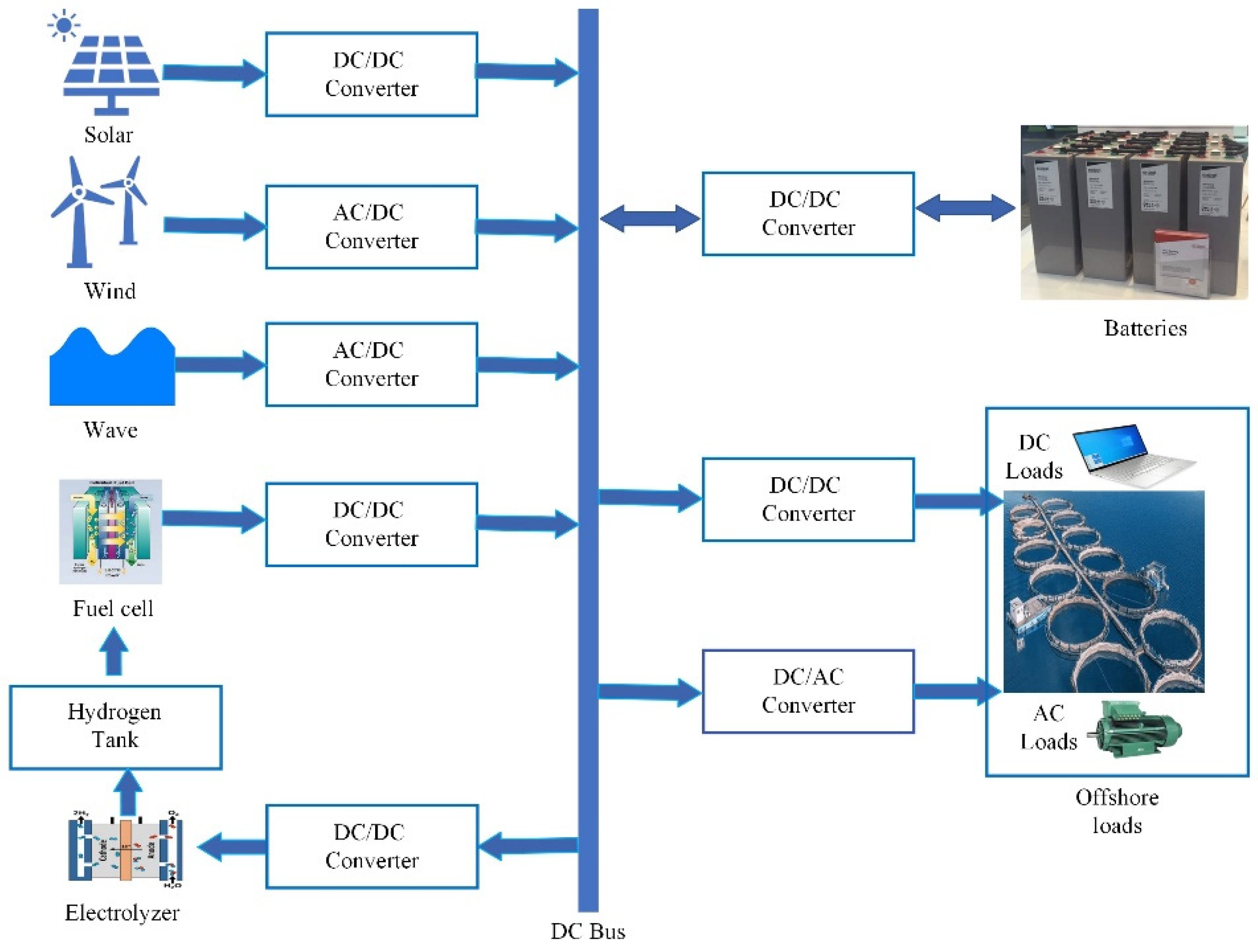
Figure 2.
Simulation model of proposed DC MG.
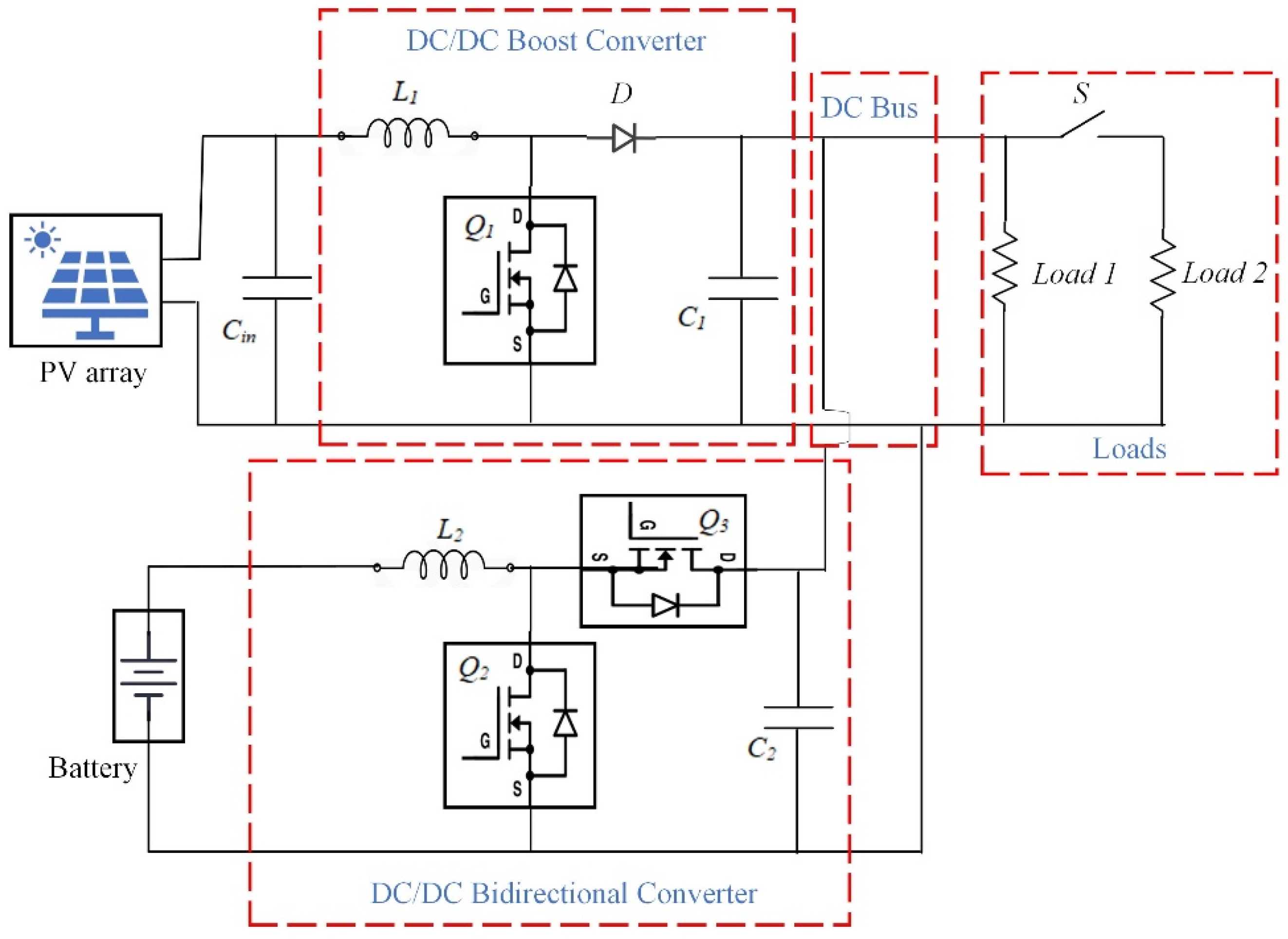
Figure 3.
Cascaded control structure for DC-DC bidirectional converter.

Figure 4.
Modified cascaded control structure.
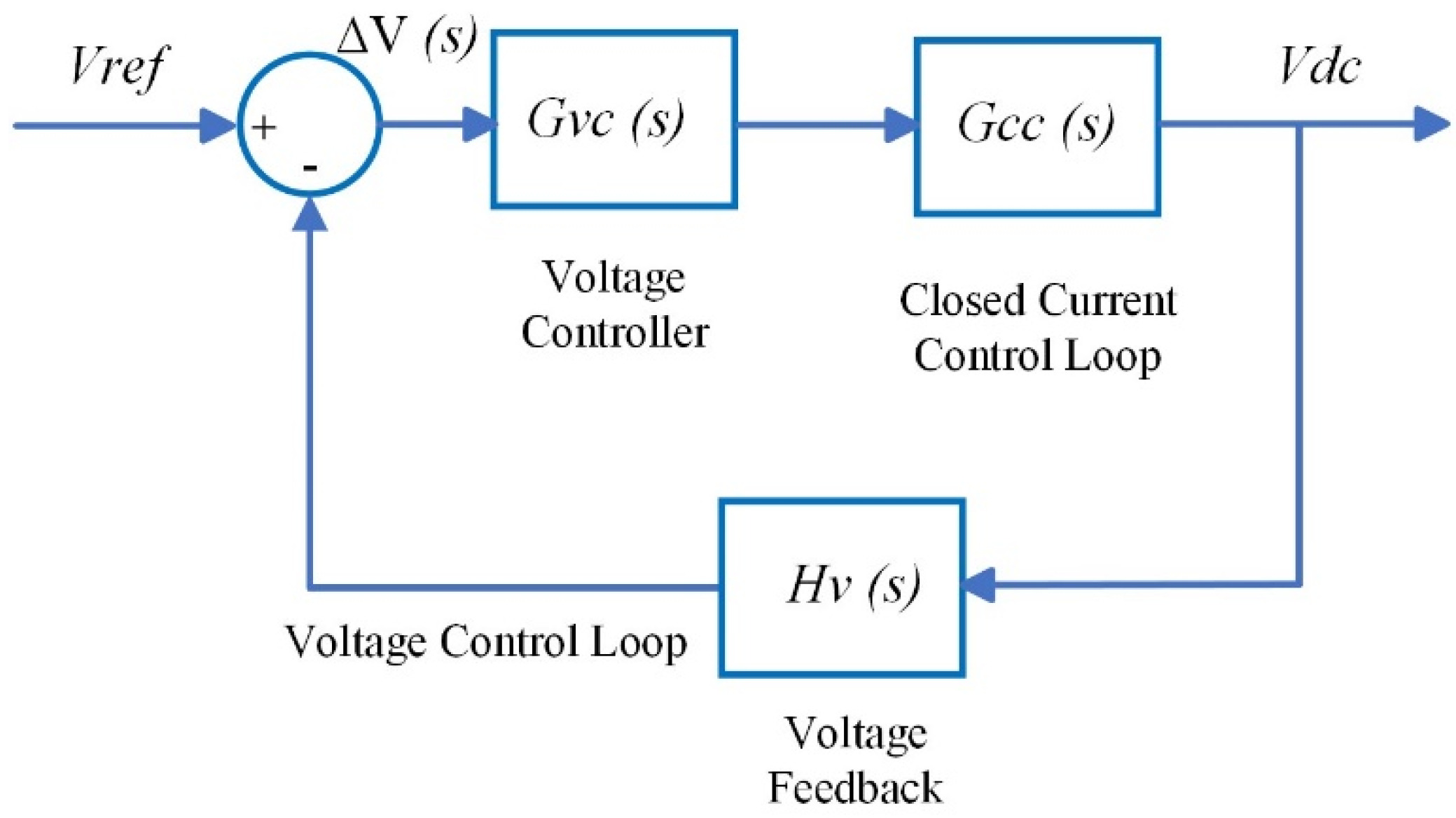
Figure 5.
Root locus for varying current controller gain, Kic.
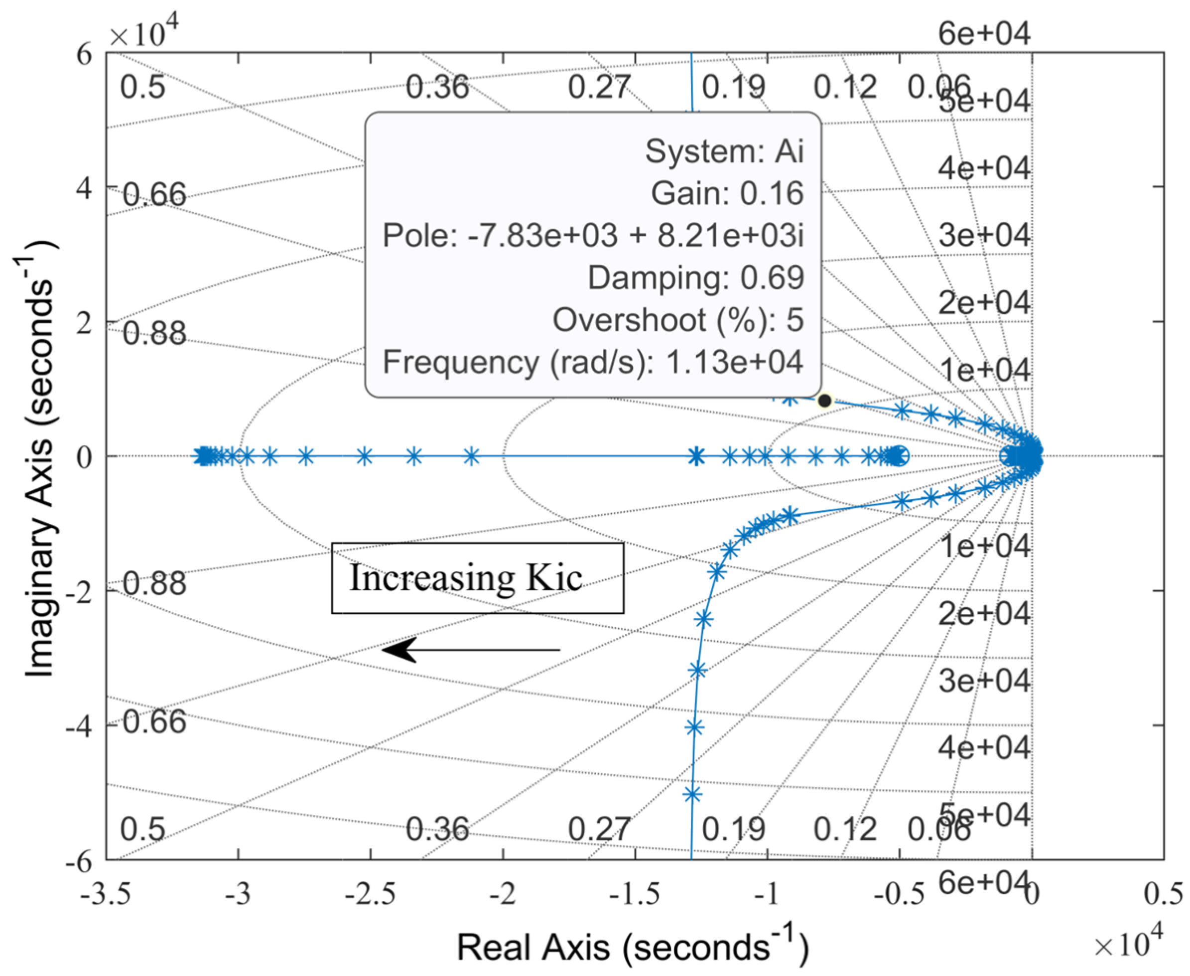
Figure 6.
Root locus for varying voltage controller gain, Kvc.
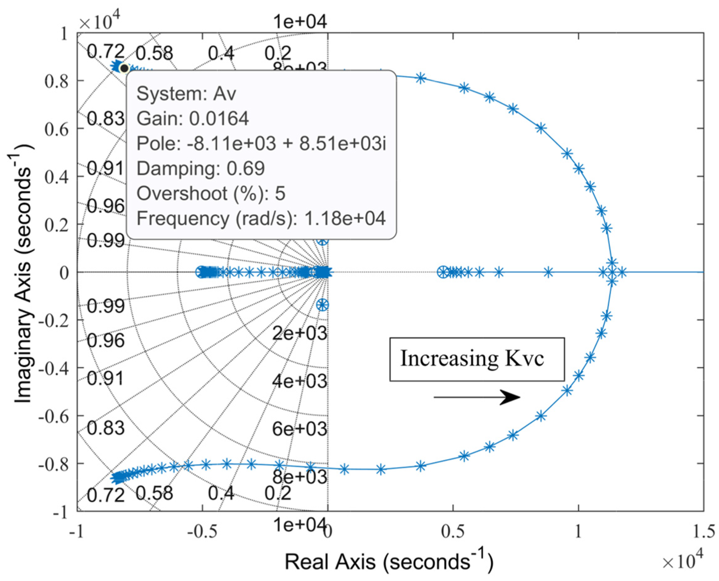
Figure 7.
Locations of dominant poles.
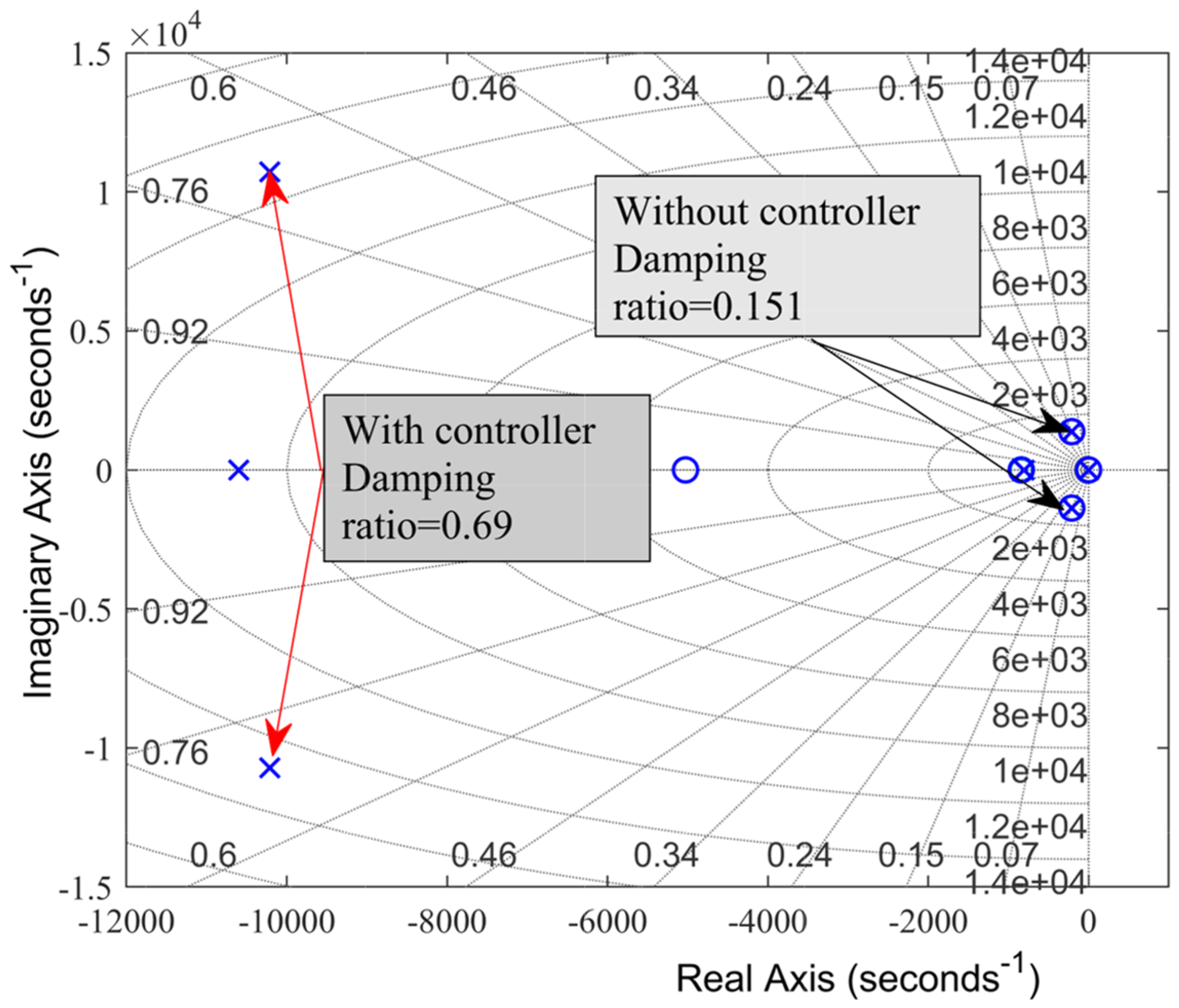
Figure 8.
Transient response comparison between ACM and PID controller.
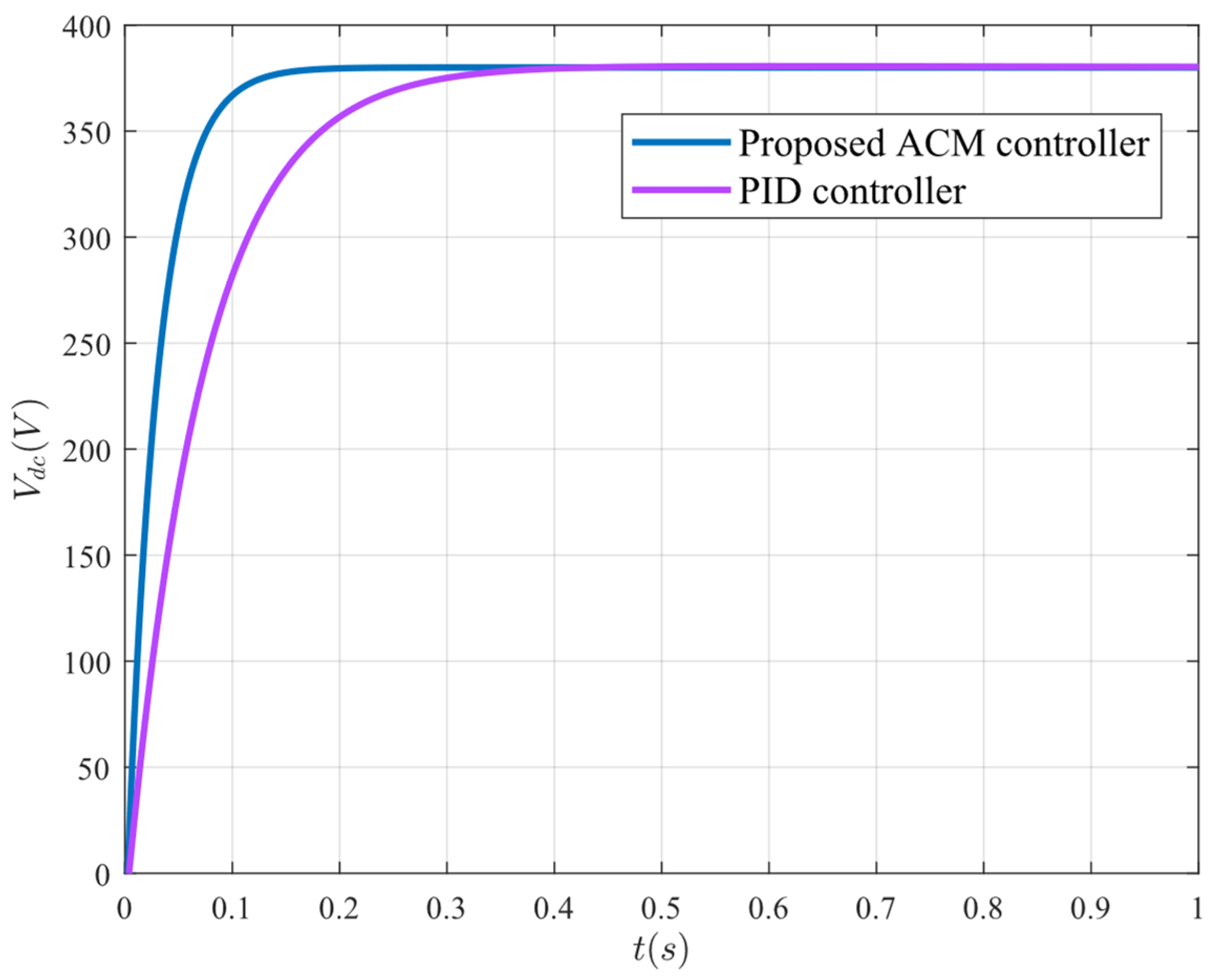
Figure 9.
Frequency response comparison between ACM and PID controller.
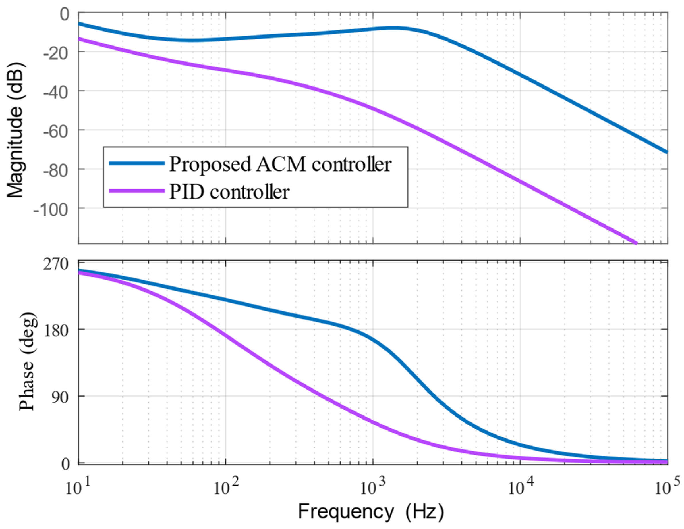
Figure 10.
System response under load increase: (a) load power, (b) PV power, and (c) bus voltage.
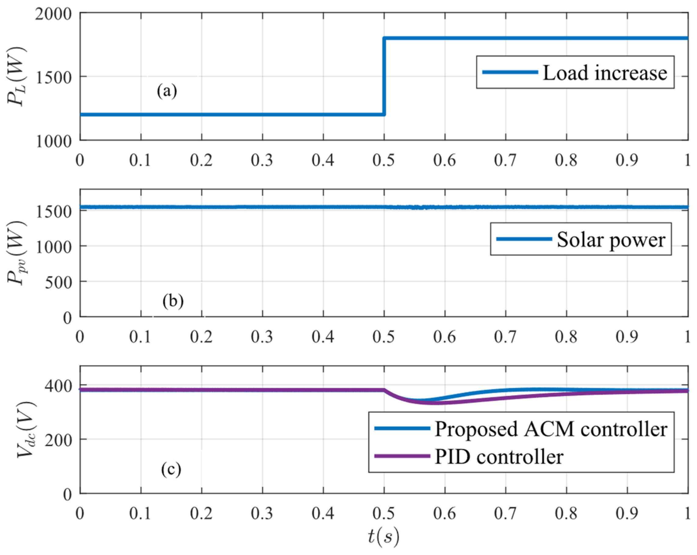
Figure 11.
Battery conditions under load increase: (a) battery voltage, (b) battery current, and (c) battery SoC.
Figure 11.
Battery conditions under load increase: (a) battery voltage, (b) battery current, and (c) battery SoC.
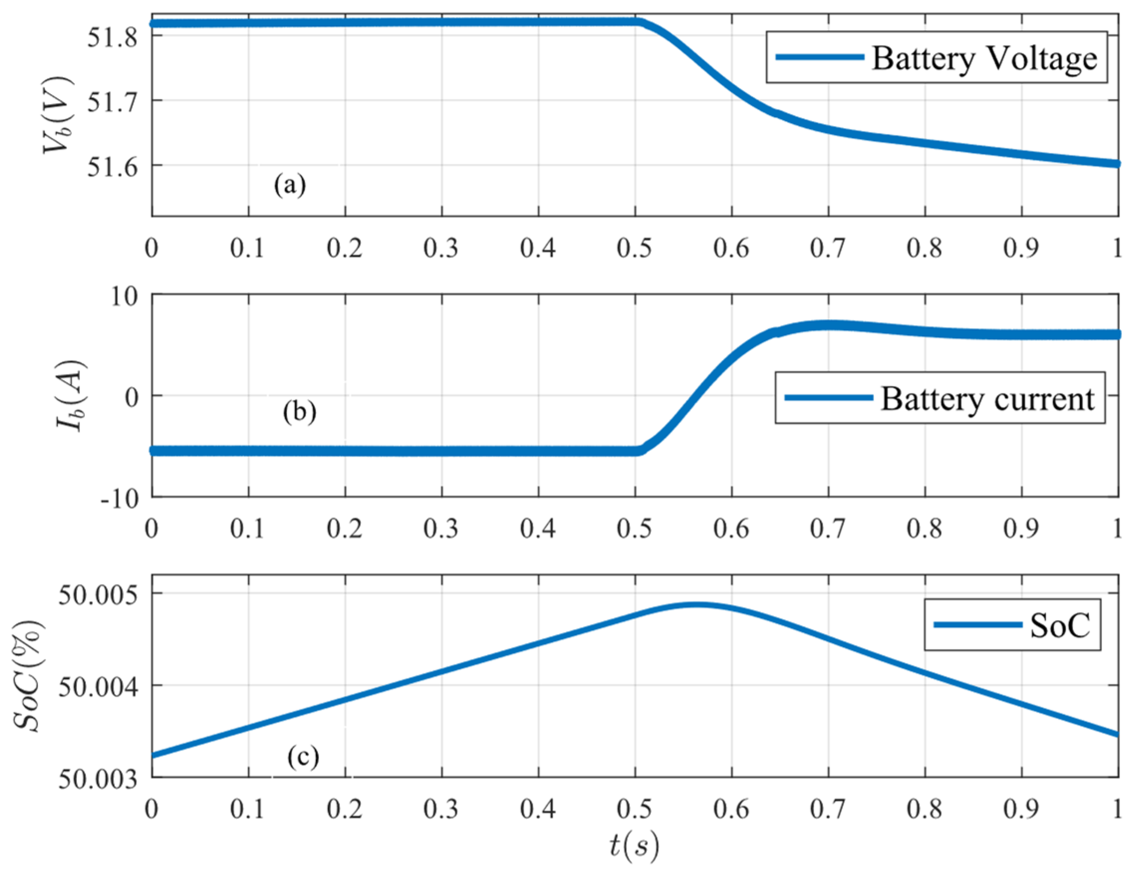
Figure 12.
System response under load decrease: (a) load power, (b) PV power, and (c) bus voltage.
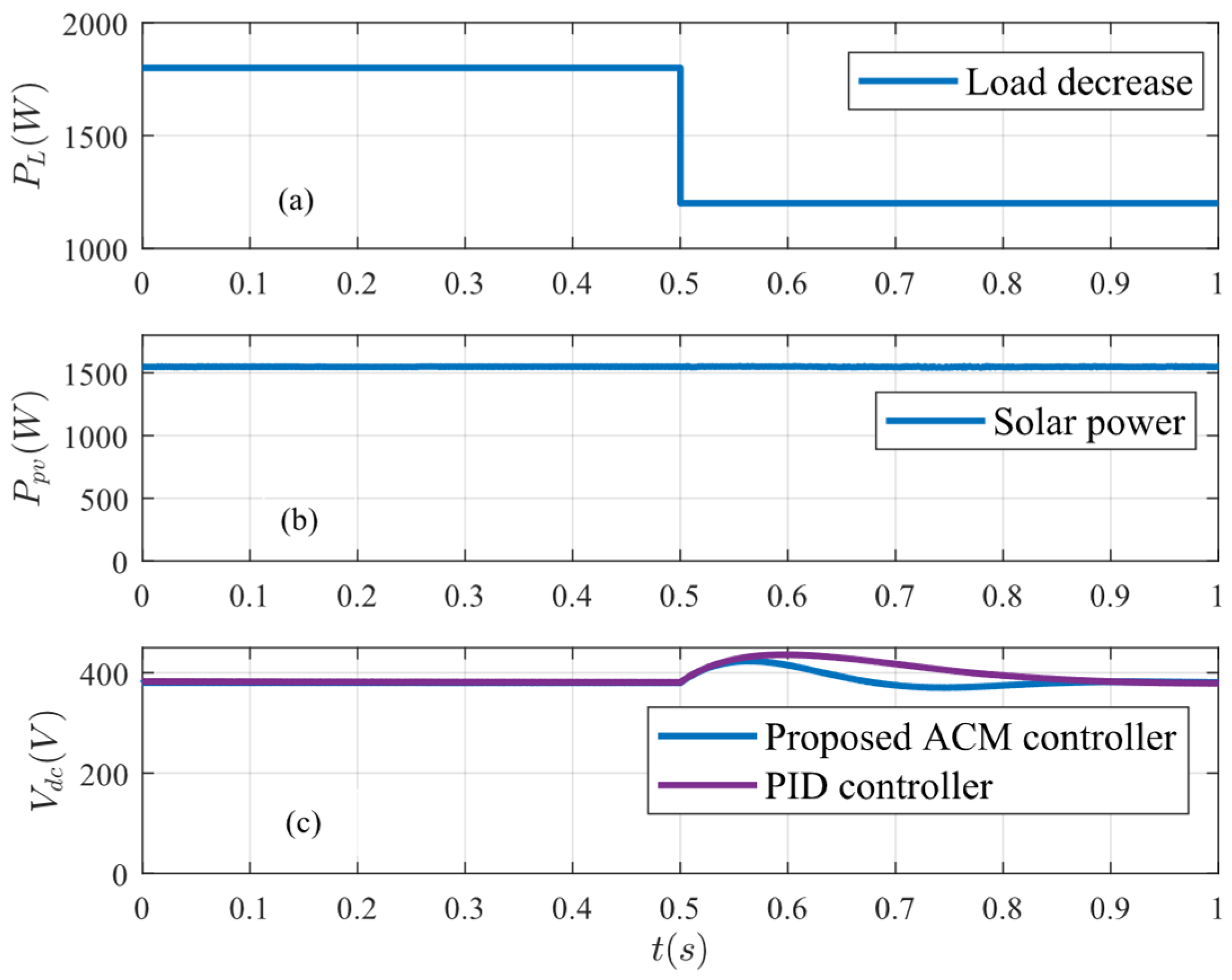
Figure 13.
Battery conditions under load decrease: (a) battery voltage, (b) battery current, and (c) battery SoC.
Figure 13.
Battery conditions under load decrease: (a) battery voltage, (b) battery current, and (c) battery SoC.
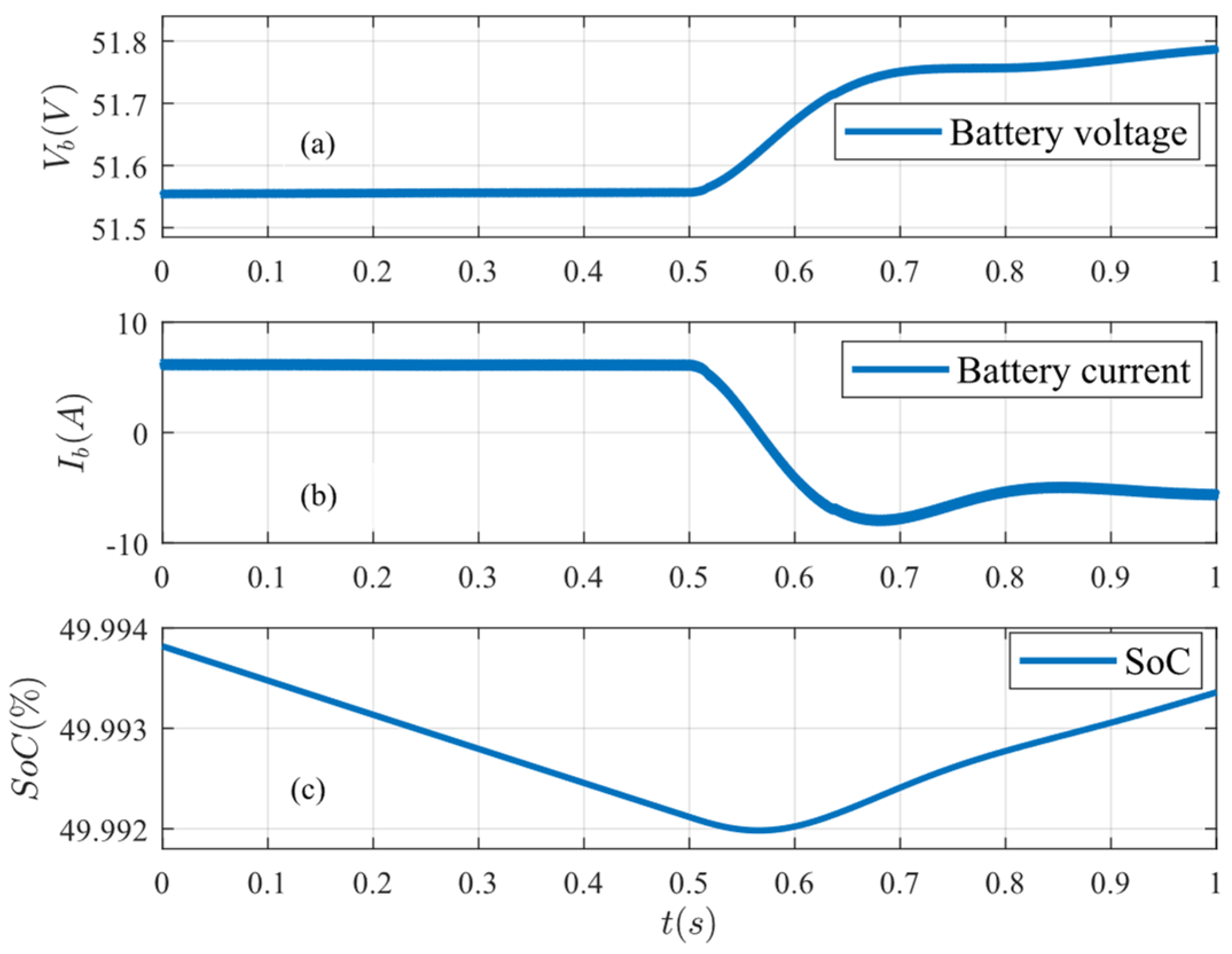
Figure 14.
System response under generation variations: (a) solar irradiance, (b) PV power, and (c) bus voltage.
Figure 14.
System response under generation variations: (a) solar irradiance, (b) PV power, and (c) bus voltage.
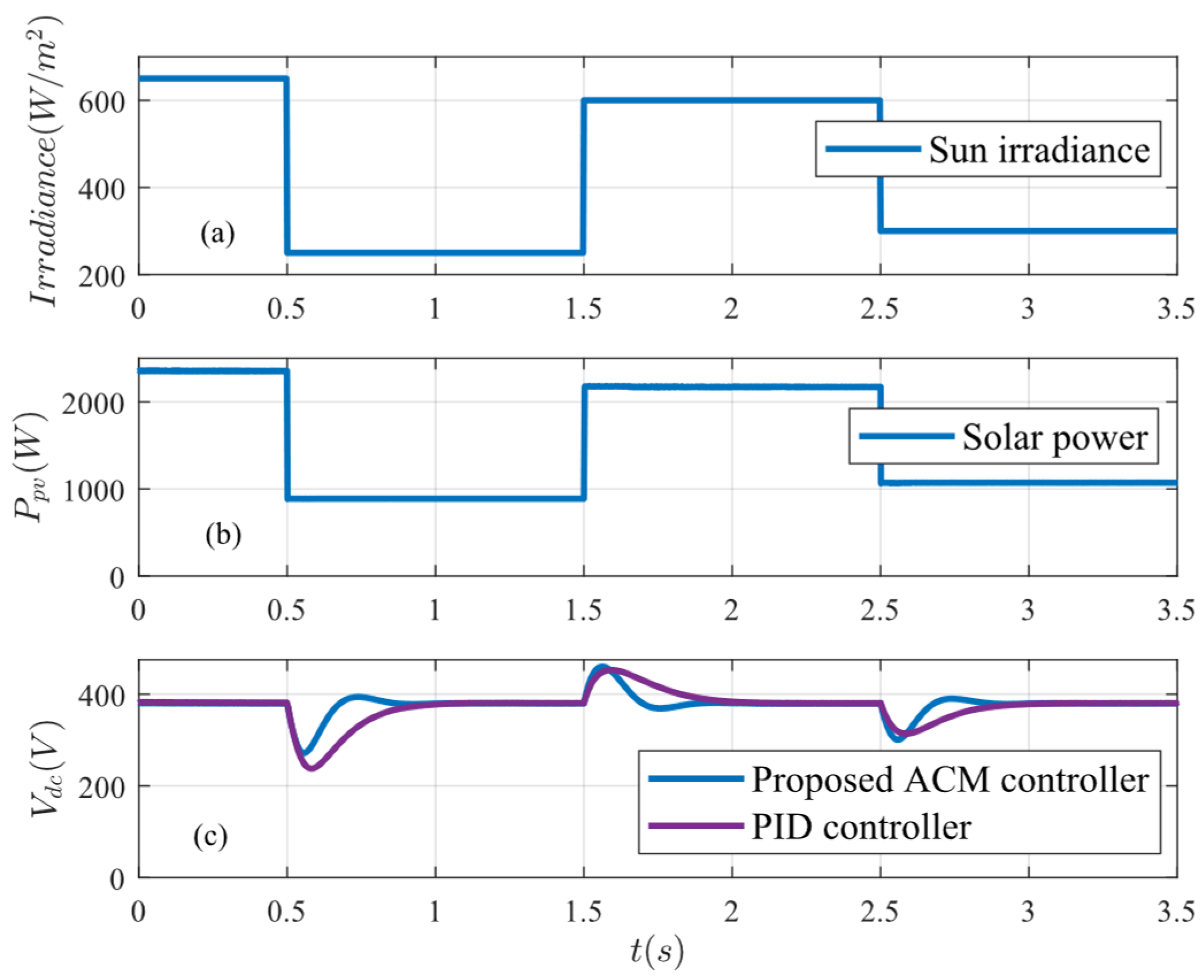
Figure 15.
Battery conditions under generation variations: (a) battery voltage, (b) battery current, and (c) battery SoC.
Figure 15.
Battery conditions under generation variations: (a) battery voltage, (b) battery current, and (c) battery SoC.
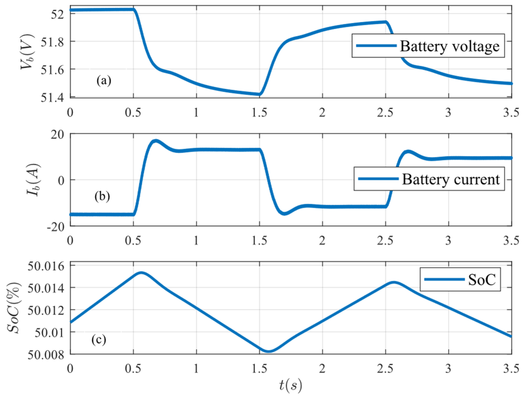
Figure 16.
Effect of the dominant pole due to load variations.
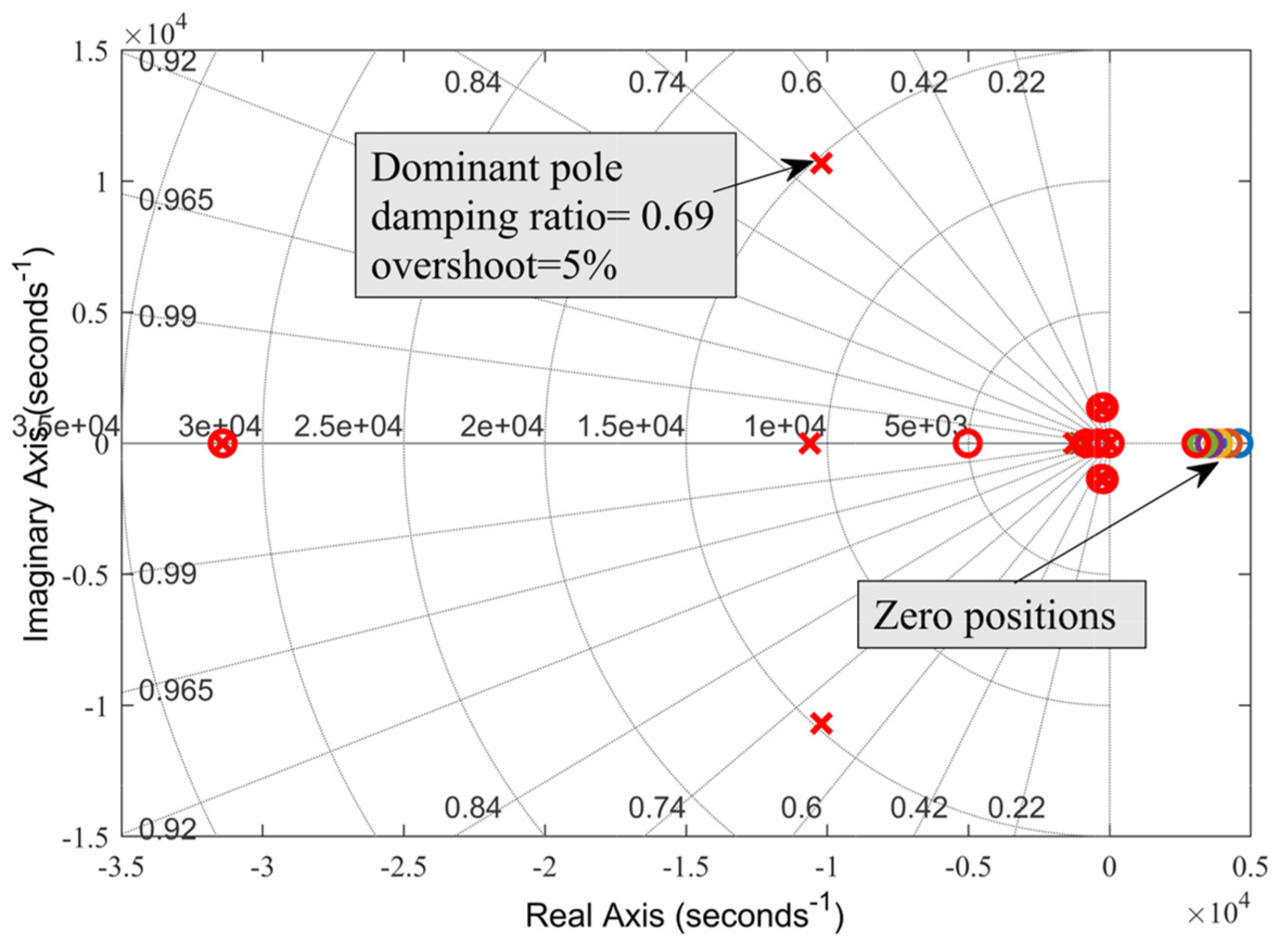
Figure 17.
Effect of the dominant pole due to inductance variations.
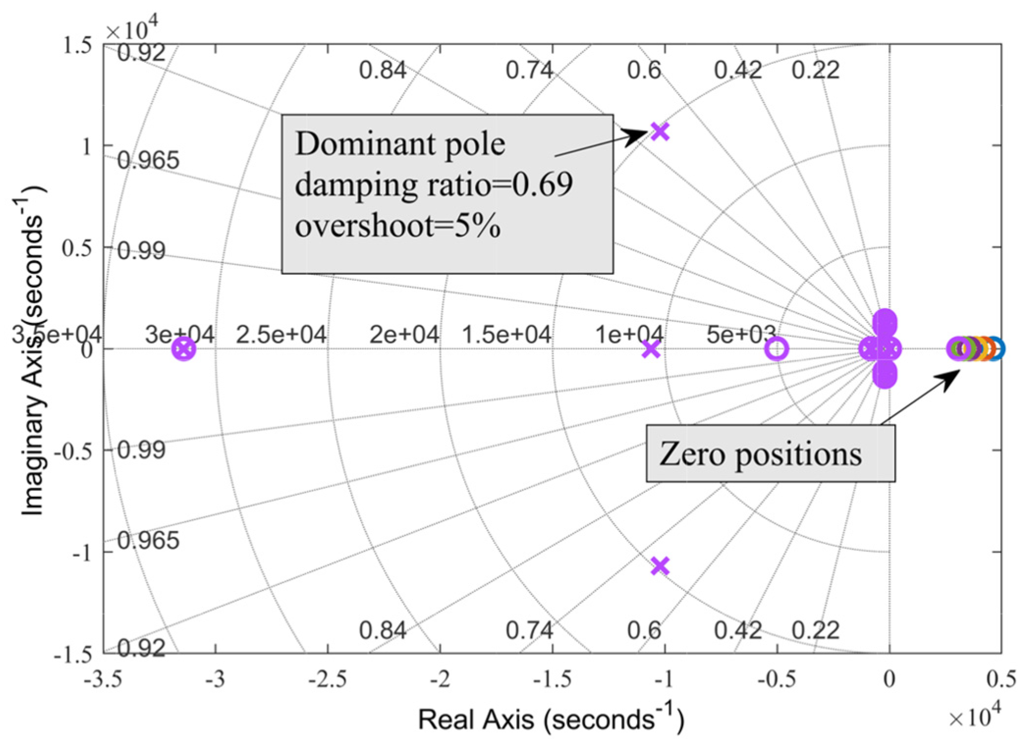

Table 1.
System performance specifications.
| Performance specification | Value | |
|---|---|---|
| PID controller | Proposed ACM controller | |
| Rise time (ms) | 155 | 63 |
| Settling time (ms) | 274 | 117 |
| Phase margin (degree) | 86 | 84 |
| Gain margin (dB) | 28 | 10 |
| Bandwidth (Hz) | 14 | 35 |
Table 2.
System parameters.
| Parameter | Value |
|---|---|
| Load power and DC bus voltage | 2 kW and 380 V |
| Battery capacity and terminal voltage | 50 Ah and 48 V |
| PV power | 1.5 kW |
| Inductance, L1, L2 | 470 µH and 5 mH |
| Capacitance, C1, C2 | 1000 µF and 33 µF |
| Switching frequency | 20 kHz |
| Target crossover frequency for current loop compensator | 2 kHz |
| Target crossover frequency for voltage loop compensator | 0.2 kHz |
| Current and voltage feedback gain, Hi, Hv | 1 and 1 |
Table 3.
System performance specifications under load variation.
| Performance specification | Value | |
|---|---|---|
| PID controller | Proposed ACM controller | |
| Settling time (ms) | 260 | 120 |
| Voltage regulation (%) | 0.08 | 0.05 |
| THD (%) | 0.04 | 0.03 |
| IAE | 48.01 | 22.48 |
| ITAE | 35.94 | 7.9 |
Table 4.
System performance specifications under generation variation.
| Performance specification | Value | |
|---|---|---|
| PID controller | Proposed ACM controller | |
| Settling time (ms) | 340 | 140 |
| Voltage regulation (%) | 0.08 | 0.05 |
| THD (%) | 0.05 | 0.02 |
| IAE | 109.87 | 37.05 |
| ITAE | 241.2 | 59.79 |
Disclaimer/Publisher’s Note: The statements, opinions and data contained in all publications are solely those of the individual author(s) and contributor(s) and not of MDPI and/or the editor(s). MDPI and/or the editor(s) disclaim responsibility for any injury to people or property resulting from any ideas, methods, instructions or products referred to in the content. |
© 2025 by the authors. Licensee MDPI, Basel, Switzerland. This article is an open access article distributed under the terms and conditions of the Creative Commons Attribution (CC BY) license (http://creativecommons.org/licenses/by/4.0/).
Copyright: This open access article is published under a Creative Commons CC BY 4.0 license, which permit the free download, distribution, and reuse, provided that the author and preprint are cited in any reuse.


