
Submitted:
30 January 2026
Posted:
02 February 2026
You are already at the latest version
Abstract
This research investigates the validation of hermeticity in 3D-printed vacuum enclosures for smart façade systems, highlighting the critical need for airtightness in architectural applications. Using a pressure decay leak testing method under vacuum, guided by BS EN 1779:1999 criteria for method selection and based on ASTM F2095 − 07 (Reapproved 2021) standards, we created a controlled depressurization of the enclosure up to 1 bar with a manual vacuum pump. Different depression values were read at intervals of 20, 40 and every 60 minutes to detect any drops indicative of leakage. The results demonstrated that our method reliably identified even minor leaks, with constant pressure stability confirming the hermetic integrity of the housing. These findings suggest that our approach provides a practical, low-cost, and non-destructive measure for complex 3D printed components in advanced façade systems. Moreover, the methodology is adaptable to various geometries and materials, providing manufacturers with an effective tool to ensure the reliability and performance of integrated facades of smart buildings.
Keywords:
3D-printed enclosures
; vacuum leak testing
; hermeticity
; ASTM F2095
; BS EN 1779
; smart façades
; leak detection
; additive manufacturing
; quality control
; non-destructive testing
; architectural applications
1. Introduction
Recent advancements in additive manufacturing technologies, particularly three-dimensional (3D) printing, have significantly transformed the landscape of architectural design and fabrication. This innovative approach allows for the production of highly complex architectural components that were previously challenging or impossible to achieve through traditional manufacturing methods. Smart façade systems, characterized by their use of advanced materials and intricate geometries, have emerged as an influential application area within this context.
These smart façade systems [1] leverage cutting-edge materials that can respond dynamically to environmental conditions, thereby enhancing energy efficiency and sustainability in buildings. For instance, materials that exhibit phase change properties enable thermoregulation, responding to temperature variations by absorbing or releasing heat. Moreover, the integration of photovoltaic elements can facilitate on-site energy generation, further promoting sustainability.
To illustrate how 3D printing enables the creation of innovative and visually impressive structures, combining aesthetics with advanced functionality, Figure 1 presents an abstract figure created by the author showcasing a 3D-printed smart façade. This image highlights a concrete application of the discussed technologies, demonstrating the capability to integrate complex details, such as vacuum cells, into a unique and attractive architectural form.
The design of smart façades is not only driven by functional requirements but also by aesthetic considerations. The ability to create unique and appealing visual patterns through 3D printing supports architects in pushing the boundaries of traditional design, enabling innovative and visually striking structures that can blend seamlessly into their surroundings while contributing to urban beauty.
The article “Future trends and main concepts of adaptive facade systems” [2] by Attia, Lioure, and Declaude (2020) provides a fundamental insight into the future directions of adaptive façade systems, addressing an existing gap in the literature regarding emerging trends. Through a rigorous methodology, which included in-depth interviews with 27 international experts, content analysis, and an extensive literature review, the authors developed a novel conceptual framework and an innovative technological classification. This classification groups adaptive façade technologies into four main categories: dynamic shading [3], chromogenic façades [4], solar active façades [5], and active ventilative façades [6]. The study also highlights that human-centered design, smart building operating systems, service-driven solutions, and the principles of circularity and materials represent the main conceptual pillars that will shape future advancements in this field, offering essential insights for all stakeholders involved in architectural design, manufacturing, and regulation.
Building on the crucial role of materials in adaptive systems, the article by Haleema Jaffar et al. (2024), titled “Critical analysis of smart materials in adaptive transparent systems for building façade,” [7] provides a critical analysis of smart materials used in adaptive transparent systems (ATS) for building façades. Their research aims to enhance energy efficiency and user comfort through dynamic adaptation to environmental conditions. Through an extensive literature review and multi-criteria decision-making techniques (AHP and TOPSIS) [8], the study identified and evaluated seven key smart materials, concluding that photovoltaic (PV) materials are most optimal for ATS applications. This work underscores the significant potential of smart material technologies for future research in adaptive façades.
Central to the optimal functioning of these smart façade systems [9] is the incorporation of hermetically sealed vacuum enclosures. These enclosures play a multifaceted role in enhancing the performance and durability of architectural components. First and foremost, they provide thermal insulation by creating a barrier against heat transfer, which is vital for maintaining comfortable indoor temperatures and reducing energy consumption for heating and cooling. Additionally, the use of vacuum environments can significantly dampen sound transmission, offering acoustic benefits that improve occupant comfort by minimizing external noise interference.
Beyond thermal and acoustic performance, hermetically sealed enclosures also facilitate the integration of embedded sensing capabilities. This capability allows for the monitoring of environmental conditions, structural integrity, and energy performance in real-time, contributing to the smart functionality of the buildings. Sensors can collect data on humidity, temperature, air quality, and other parameters, enabling responsive adjustments to building operations and enhancing overall user experience.
Further demonstrating the versatility of smart façade systems, the article by Khalid M. Abdelaziz et al. (2021), titled “A smart façade system controller for optimized wind-induced vibration mitigation in tall buildings,” [10] addresses the critical issue of wind-induced vibrations (WIV) in tall buildings, which can cause discomfort to occupants and structural damage. The research proposes and validates an intelligent façade control system, based on an adaptive, data-driven strategy that utilizes an actively adjustable, morphing façade system, demonstrating significant WIV reduction through FSI simulations. This adaptive approach represents a promising solution for improving structural performance and comfort in tall buildings by dynamically adapting to variable wind conditions.
As the field of smart façades continues to evolve, ensuring the hermeticity of these 3D-printed vacuum [11] enclosures becomes imperative. Even minor leaks can compromise the effectiveness of thermal insulation, reduce acoustic damping, and adversely affect the reliability of embedded sensors, leading to potential failures in the system’s intended functions. To effectively harness the advantages of these technologies, it is crucial to develop robust leak detection methodologies and quality assurance protocols tailored to the unique challenges presented by the geometrical complexity and material diversity of additively manufactured architectural components. This exploration will pave the way for enhanced performance and durability in the innovative façade systems driving the future of sustainable architecture.
1.1. Importance of Hermeticity in 3D-Printed Enclosures
The integrity of 3D-printed enclosures [12], particularly their hermeticity, stands as a paramount concern in numerous high-stakes applications. Ensuring an impermeable barrier is not merely a design preference but a critical functional requirement, as even minimal leaks can compromise system performance, lead to the catastrophic failure of integrated functionalities, or create severe long-term structural integrity issues.
For sensitive electronic components or embedded sensors [13], even minute moisture or contaminant ingress due to non-hermetic seals can cause corrosion, short circuits, signal drift, and ultimately, premature device failure. In biomedical devices and pharmaceutical packaging, hermeticity is non-negotiable for maintaining sterility, preventing biological contamination, and ensuring drug stability and patient safety. Similarly, in aerospace and automotive sectors, where components are exposed to extreme temperature fluctuations, pressure differentials, and aggressive fluids, compromised hermeticity can lead to critical malfunctions, loss of vacuum in sensitive instruments, or leakage of hazardous substances. In energy systems or chemical processing, it’s vital for containment, efficiency, and safety.
The inherent characteristics of additive manufacturing processes [14] introduce unique and significant challenges to achieving and verifying truly hermetic seals. Unlike traditional manufacturing, where material homogeneity and well-defined interfaces are often assumed, 3D printing builds objects layer-by-layer. This layered deposition can create anisotropic properties, internal voids, micro-porosity, or imperfect layer adhesion, especially when dealing with intricate geometries, internal channels, or multi-material constructs. These microscopic pathways are often invisible to the naked eye and can bypass conventional inspection techniques.
Eickenscheidt et al. (2021) [15] investigated the production of hermetic alumina housings through 3D printing, leveraging the inherent gas tightness of ceramics for applications such as implantable devices. Their work demonstrated the capability of Fused Filament Fabrication (FFF) to produce complex geometries from alumina, including integrated 500 µm channels and closed hemispheres without support structures, opening new avenues for personalized device manufacturing. Despite specific challenges in 3D printing ceramics, such as significant shrinkage (16.7%) during sintering and surface roughness (Ra = 15–20 µm), the study confirmed that internal hollow structures do not compromise mechanical integrity. The developed alumina material achieved excellent gas tightness, with leakage rates below 10^-12 mbar s^-1, verified by a specially designed volume-free helium leak test device. Furthermore, the successful application of high-adhesion platinum coatings paves the way for functionalized ceramic components, establishing the fundamental prerequisites for creating hermetic housings with integrated metallic structures and a new level of complexity in ceramic design.
While ceramics offer significant advantages for hermeticity, particularly in complex 3D-printed forms, the use of other materials, such as polymers, presents its own set of challenges, especially in critical applications like medical implants. In an in-depth review of welding methods for joining thermoplastic polymers to achieve hermetic enclosures for medical devices, Amanat, James, and McKenzie (2010) [16] highlighted the critical importance of hermeticity for the integrity of internal components and patient safety. The study emphasizes that while titanium remains the gold standard for implant encapsulation due to its biocompatibility and laser weldability, new high-performance polymers offer a promising alternative. However, the major challenges for widespread acceptance of polymers lie in their inherent permeability to water vapor and the difficulty of creating a hermetic join with an extended lifespan. The authors examine various thermal bonding techniques, identifying laser welding as the method of choice, even though it requires substantial research to establish optimal process parameters. This work underscores the complexity of achieving reliable and durable hermeticity, especially with polymeric materials, a fundamental issue that extends to enclosures manufactured using additive techniques.
Expanding on the critical aspects of achieving reliable hermeticity with polymeric materials, particularly for applications reliant on flexible sealing, Bamps, Buntinx, and Peeters (2023) [17] further detail the role of seal materials in flexible plastic food packaging. Their comprehensive review emphasizes the non-negotiable importance of seal performance for food safety and quality, highlighting that flexible packaging, while offering advantages in weight and cost, relies heavily on efficient heat sealing techniques to achieve the necessary tightness. They delve into the mechanisms of heat sealing, including polymer chain diffusion and entanglement, and systematically categorize seal materials based on chemical structure, covering polyolefins, ethylene copolymers, and polyesters, while also discussing the influence of plasticizers, fillers, and other additives on seal performance. Crucially, the review underscores that beyond mere mechanical strength, tightness is paramount for preventing food degradation by microorganisms and external gases, and for retaining aromatic compounds, ultimately aiming to support industry stakeholders in optimizing material selection to achieve seals with desired properties.
A study conducted by May, Eslami, and Fouladi (2022) [18] investigated the critical impact of humidity conditions on print quality and the mechanical properties of plastic filaments in additive manufacturing. Using a combined approach of computational fluid dynamics (CFD) simulations and experimental testing, the research aimed to optimize the environment within a 3D printer enclosure to achieve a more uniform relative humidity (RH) distribution in the print volume. The results demonstrated a significant improvement in RH uniformity – simulations predicted an increase of approximately 65%, while experimental tests indicated an even more substantial improvement of about 75%. A case study involving NinjaFlex© filaments [19] printed under optimized environmental conditions showed an 11% increase in ultimate strength and more elastic behavior of the material compared to samples printed using the baseline model, underscoring the importance of precise environmental control in 3D printing processes.
Consequently, traditional leak detection methodologies, typically optimized for simpler geometries and uniform materials, often fall short. They may lack the required sensitivity to detect micro-leaks (on the order of 10^-5 Pa m³/s or less) or struggle to provide comprehensive coverage for the complex internal structures and heterogeneous material distributions characteristic of 3D-printed designs. The imperative, therefore, extends beyond mere detection to a holistic approach encompassing design for hermeticity, meticulous process control during fabrication, and the development of advanced, non-destructive evaluation techniques [20] capable of accurately and reliably verifying the integrity of these next-generation enclosures.
Table 1 provides a comprehensive overview of the importance of hermeticity in 3D-printed enclosures, highlighting key concerns, applications, challenges, and concluding insights related to this critical aspect of design and manufacturing.
1.2. Effective Leak Detection Techniques
Vacuum leak detection techniques [22] are fundamentally rooted in the physical principles of gas migration under pressure differentials. These techniques leverage the inherent properties of gases to migrate through even the minutest of openings, allowing for the detection of leaks that conventional methods might fail to identify. The sensitivity of vacuum leak detection is particularly advantageous in applications where the integrity of hermetic seals is critical, such as in the electronics, biomedical, and aerospace industries. By creating a controlled vacuum environment, these methods can effectively amplify the detection of any gas that escapes from the enclosure, thus ensuring that potential failures can be identified before they lead to catastrophic consequences.
The guidelines established by ASTM F2095 − 07 [23] (Reapproved 2021) serve as a comprehensive framework for standardized leak testing procedures, providing a systematic approach for conducting these evaluations under controlled conditions. Adherence to these standards not only ensures the repeatability of tests but also facilitates the comparability of results across various laboratories and manufacturing environments. This is essential for maintaining quality control and compliance within regulated industries, where even minor deviations can have significant impacts on product performance and safety.
In addition to specific test method standards like ASTM F2095, broader European guidelines, such as BS EN 1779:1999 ‘Non-destructive testing — Leak testing — Criteria for method and technique selection,’ [24] provide a foundational framework for systematically selecting appropriate leak detection techniques based on critical factors such as application requirements, material properties, and operational conditions. This standard’s comprehensive approach to method selection is particularly pertinent when addressing novel challenges in leak testing, such as those encountered with additively manufactured components.
Further illustrating the application and rigorous validation of such standardized approaches, Langlois, Hogreve, and Cappia (2017) [25] addressed the critical need for reliable leak detection in single-use bag assemblies, prevalent in biopharmaceutical manufacturing. The widespread adoption of single-use technologies in increasingly critical processes, such as drug substance storage, has made assembly integrity a paramount concern, as failures in these high-value product environments can incur substantial financial losses. To mitigate these risks and align with quality risk management strategies (ICH Q9), the authors developed and validated a highly sensitive point-of-use pressure decay test. This method, rooted in the principles of ASTM F2095-01, was rigorously validated across a range of 2D storage bags (50 mL to 50 L) using specialized equipment. Their validation study demonstrated the test’s robustness, achieving a 99.9% probability of differentiating defective from non-defective bags and establishing a precise maximum allowable pressure decay of 3.1 mbar with a 6σ confidence interval. Crucially, the developed non-destructive method proved capable of reliably detecting defects down to 10 µm, a sensitivity that remained independent of the bag’s volume. This advancement offers biopharmaceutical manufacturers a predictive and efficient tool for pre-use leak testing, enhancing product quality, patient safety, and operational reliability.
The implementation of vacuum leak detection techniques, complemented by established standards, fosters a rigorous approach towards achieving and verifying hermeticity in 3D-printed enclosures. As such, these methodologies play a pivotal role in advancing the reliability of products designed for high-stakes applications, thereby enhancing confidence in their structural and functional integrity.
Beyond the specific context of 3D-printed enclosures, the broader field of leak detection strategies has been extensively reviewed. For instance, Zaman et al. (2019) [26] undertake a comprehensive review of strategies for leakage detection in pressurised pipelines operating under steady-state conditions, serving as a critical resource for understanding this complex domain. The authors underscore the paramount importance of pipeline integrity management, emphasizing its role not only in ensuring continuous operational functionality but also in mitigating severe financial losses, environmental degradation, and potential risks to human life associated with leaks and bursts. Given the overwhelming diversity and varying technical complexities of available detection methodologies, the study provides a performance-oriented critical evaluation of various leak detection approaches applicable to pipelines transporting diverse fluids, such as drinking water, oil, and natural gas. A key contribution is the systematic classification of these methods, distinguishing between hardware-based, software-based, and advanced hybrid approaches, based on their core methodologies and application characteristics. Notably, the review highlights that hybrid methods demonstrate enhanced efficiency, offering superior accuracy and reduced error rates in leak localization compared to standalone techniques. This comprehensive assessment serves to contextualize the challenges inherent in evaluating the vast array of leak detection solutions, thereby guiding practitioners toward more effective and robust leak prevention and detection strategies.
Complementing this broader perspective on pipeline integrity, Ramadevi, Jaiganesh, and Krishnamoorthy (2018) [27] , in their conference paper “Leak Detection Methods—A Technical Review,” further highlight the critical importance of effective leak detection in pipelines for the safe transmission of various fluids and gases. Motivated by the severe consequences of hazardous leaks, such as property damage and loss of life, the authors undertake a comprehensive review of existing technologies. Their work aims to identify a leak detection approach that is not only easy to implement, adaptable, flexible, and inexpensive, but also efficient for real-time distributed data acquisition and monitoring. A key focus of their comparison is the performance and ability of different systems, particularly regarding their leak detection capabilities, false alarm rates, and overall cost-effectiveness. This review serves as a valuable resource for selecting optimal leak detection technologies for pipeline integrity management.
Further contributing to the academic discourse on leak detection methodologies, Colombo, Lee, and Karney (2009) [28], in their “selective literature review” published in the Journal of Hydro-environment Research, provide a comprehensive overview of transient-based leak detection methods. The authors aim to summarize the historical development, current state-of-the-art, and key themes within this research area. They highlight the fundamental principles behind transient-based detection, which leverage hydraulic phenomena and pressure wave behavior to identify leaks. While acknowledging significant advancements and a wide array of proposed methodologies, Colombo et al. critically observe a general lack of extensive field validation and practical verification for many of these techniques. This underscores a persistent gap between theoretical developments and real-world applicability, suggesting a continued need for robust empirical testing to advance the field.
To facilitate a clearer understanding of the diverse leak detection methodologies and contributing studies discussed in this section, Table 2 provides a concise summary of their key characteristics, focus, and relevance.
1.3. Knowledge Gap in Application of Vacuum Leak Testing
The field of vacuum leak detection boasts a rich and established history, with foundational works like Urban K. Cummings’ 1972 paper, “Vacuum Leak Detection,” [29] comprehensively outlining its principles, diverse methods (e.g., ultrasonic, pressure decay, mass spectrometry), and practical considerations such as sensitivity and cost. This extensive body of knowledge underscores the proven effectiveness of vacuum-based leak testing across various traditional industrial applications. However, despite this well-established efficacy and widespread adoption of vacuum-based leak testing across various traditional industrial applications, a distinct and critical knowledge gap persists regarding its specific deployment and validation for complex, additively manufactured architectural components, particularly those integrated into advanced façade systems. While standard vacuum leak detection techniques offer proven sensitivity and reliability for conventional sealed structures, the unique characteristics inherent to 3D-printed architectural elements, such as their often large scale, intricate internal geometries, potential for material anisotropy, and variable wall thicknesses, introduce novel challenges that may not be adequately addressed by off-the-shelf protocols. These components, intended for demanding external environments, necessitate a level of hermetic integrity that must be rigorously verified to prevent performance degradation, energy inefficiency, and structural compromise over their operational lifespan. Addressing this specific lacuna, the present research is explicitly designed to adapt and rigorously validate a tailored leak testing protocol. This protocol will be fundamentally based on the robust principles outlined in ASTM F2095, a standard conventionally applied to nonporous flexible packages, thereby ensuring a foundation of methodological rigor. The adaptation will critically consider the unique geometrical and material constraints imposed by 3D-printed enclosures. Central to this approach is the utilization of a manually operated vacuum pump, capable of generating a maximum depression of 1 bar, a choice made to ensure both cost-effectiveness and practical applicability in diverse testing scenarios [30]. This deliberate tailoring of the vacuum testing methodology is crucial for accurately assessing the hermeticity of additive manufactured architectural components, ultimately aiming to bridge the existing knowledge gap and provide a reliable, context-specific validation framework.
1.4. Research Objectives
The following table delineates the primary research objectives of this study, providing a structured overview of the methodological, evaluative, and analytical goals underpinning this investigation into hermeticity validation for 3D-printed enclosures.

Table 3.
Research Objectives.
| Objective | Description / Detail |
|---|---|
| Methodological Development | To establish a robust and rigorously reproducible experimental protocol for the vacuum leak testing of 3D-printed enclosures, specifically tailored to address the unique geometrical and material characteristics of architectural façade components, ensuring precision and replicability. |
| Performance Evaluation | To quantitatively assess the diagnostic capabilities and reliability of the adapted vacuum leak detection method, evaluating its sensitivity in discerning micro-leaks and macro-leaks across various sizes and locations within complex internal structures of additively manufactured components. |
| Procedural Framework | To formulate a comprehensive procedural framework that facilitates the seamless integration of non-destructive evaluation (NDE) protocols [31] into the quality assurance processes during both the manufacturing and assembly stages of 3D-printed architectural elements, aiming for long-term hermetic integrity. |
| Influence Analysis | To critically investigate the intricate interdependencies between design parameters, inherent material properties, and manufacturing tolerances on the achieved hermeticity and subsequent test outcomes of the assembled enclosures, informing future optimization of design and fabrication strategies. |
1.5. Structure of the Manuscript
The manuscript is meticulously structured to systematically present the research, analysis, and findings, thereby offering a coherent and comprehensive narrative:
Section 2 embarks on a comprehensive and critical review of the pertinent literature. This section synthesizes existing knowledge on various leak detection techniques, assesses the applicability and relevance of international standards such as ISO and ASTM in the context of hermeticity, and thoroughly examines prior research pertaining to additive manufacturing specifically in architectural applications. The aim is to establish the current state of knowledge and identify the specific gaps that this study seeks to address.
Section 3 provides a detailed exposition of the methodological framework developed for this study. It meticulously delineates the selection and characterization of materials employed, specifies the equipment utilized, and offers a step-by-step description of the experimental procedures. This includes precise setup configurations tailored for 3D-printed components, definition of operational parameters, and a thorough outline of crucial safety considerations, ensuring replicability and transparency of the experimental design.
Section 4 is dedicated to the systematic presentation of the empirical findings. This section comprehensively reports the experimental results, which comprise detailed pressure decay data, quantitative estimations of leak rates, and insightful qualitative assessments derived from the conducted tests. Data visualization and statistical analyses are employed to effectively communicate the outcomes.
Section 5 engages in a critical discussion of the inherent validity and potential limitations of the established methodology. This section thoroughly explores various sources of experimental and systematic error, interprets the results in a broader scientific and practical context, and outlines the significant implications for industrial adoption and quality control within the architectural sector. It also addresses the generalizability and transferability of the findings.
Section 6 serves as a culmination of the study, synthesizing the principal findings and drawing overarching conclusions. Furthermore, it proposes strategic recommendations for future research directions, specifically targeting enhancements in the robustness, automation, and scalability of the developed leak testing protocol. These recommendations are geared towards optimizing the application of this methodology for additively manufactured components explicitly used in demanding architectural façade systems.
By meticulously establishing a detailed methodological framework and rigorously validating the experimental procedures, this research significantly contributes to the advancement of reliable leak testing techniques in the realm of 3D printing, thereby laying a crucial foundation for future studies and practical applications within diverse architectural contexts. The subsequent section will elaborate on the foundational background and relevant literature pertinent to this investigation.
2. Materials and Methods
2.1. Materials
The experiment used the following materials, all sourced as 1.75mm diameter filaments for Fused Deposition Modeling (FDM) 3D printing. Each material had three distinct testing samples.
To provide clarity on the materials employed in this study, Table 1 summarizes the various types of filaments utilized for printing the experimental chambers, including their colors and specific descriptions.
Table 4.
Filament types used in 3D printing.
| Filament Type | Color | Description |
|---|---|---|
| PLA Basic | Black | Polylactic Acid |
| PLA Aero | Light-Gray | Foaming grade of Polylactic Acid, Bambu PLA Aero |
| PETG | Clear | ReFill PETG 3D-Printing material by Formfutura |
| PET-CF | Black | Bambu PET-CF |
All materials evaluated in this study are commonly used in architectural modeling and prototyping, making them suitable as foundational elements for constructing larger structures. The selection included various blends designed for application in exterior components.
Basic PLA is a widely available printing material that is user-friendly but has limited outdoor durability, being susceptible to UV degradation in certain applications. The tested variations included both red and black base colors for improved comparison.
PETG offers a cost-effective and robust alternative, making it suitable for more demanding applications. The “clear” PETG used in this study is devoid of pigments and additives that could worsen weathering.
PLA Aero is noted for its lightweight properties, appropriate for less demanding tasks. Its unique formulation enables performance comparisons with standard PLA.
PET-CF is engineered for enhanced strength, targeting high-temperature applications.
All product datasheets recommend maintaining storage conditions with humidity levels below 20%. The datasheet for PETG highlights its waterproof characteristics but does not specify UV protection. Furthermore, all datasheets advise keeping the materials out of sunlight and away from high temperatures and humidity.
To illustrate the mechanical properties of the various filaments used in this study, Table 5 provides a detailed overview of their tensile and impact strengths, along with other relevant characteristics.
2.2. Printing Parameters (Slicer Values)
In the following section, we will present a detailed overview of the printing parameters for various filament types, including PET-CF, PETG, PLA-Aero, and PLA. This table outlines the specific slicer values determined by the author, which are crucial for optimizing print quality and achieving desired results.
Table 6.
Printing parameters for different filament types.
| Filament | PET-CF | PETG | PLA-Aero | PLA |
|---|---|---|---|---|
| Vendor | Bambu Lab | Form Futura | Bambu Lab | Bambu Lab |
| Default Color | Black | Translucent | Black | |
| Filament Diameter Flow Ratio |
1.75 mm | 1,75 mm | 1.75 mm | 1.75 mm |
| 1.0 | 0,95 | 0,6 | 0,98 | |
| Density | 1.29 g/cm³ | 1.25 g/cm³ | 1.21 g/cm³ | 1.26 g/cm³ |
| Shrinkage | 100% | 100% | 100% | 100% |
| Recommended Nozzle Temperature | Min: 260 °C, Max: 290 °C | Min: 230 °C, Max: 270 °C |
Min: 210 °C, Max: 260 °C |
Min: 190 °C, Max: 240 °C |
| Print Temperature | Initial Layer: 270 °C |
Initial Layer: 250 °C |
Initial Layer: 220 °C |
Initial Layer: 220 °C |
| Other Layers: 270 °C | Other Layers: 245 °C |
Other Layers: 220 °C |
Other Layers: 220 °C |
|
| Textured PEI Plate | Initial Layer: 100 °C | Initial Layer: 70 °C |
Initial Layer: 65 °C | Initial Layer: 65 °C |
| Other Layers: 100 °C | Other Layers: 70 °C | Other Layers: 65 °C | Other Layers: 65 °C |
|
| Max Volumetric Speed | 8 mm³/s | 6 mm³/s | 6 mm³/s | 21 mm³/s |
| Ramming Volumetric Speed | -1 mm³/s | -1 mm³/s | -1 mm³/s | -1 mm³/s |
| Nozzle Diameter | 0.4 mm | 0.4 mm | 0.4 mm | 0.4 mm |
| Layer Height | 0.12 mm | 0.12 mm | 0.12 mm | 0.12 mm |
| Initial Layer Height | 0.2 mm | 0.2 mm | 0.2 mm | 0.2 mm |
| Line Width | Default: 0.42 mm Initial Layer: 0.5 mm |
Default: 0.42 mm Initial Layer: 0.5 mm |
Default: 0.42 mm Initial Layer: 0.5 mm |
Default: 0.42 mm Initial Layer: 0.5 mm |
| Wall Loops | 10 | 10 | 10 | 10 |
| Top Surface Pattern | Concentric | Concentric | Concentric | Concentric |
| Top Shell Layers | 35 | 35 | 35 | 35 |
| Top Shell Thickness | 0,6 mm | 0,6 mm | 0,6 mm | 0,6 mm |
| Top Paint Penetration Layers | 10 | 10 | 10 | 10 |
| Bottom Surface Pattern | Rectilinear | Rectilinear | Rectilinear | Rectilinear |
| Bottom Shell Layers | 20 | 20 | 20 | 20 |
| Bottom Shell Thickness | 0 mm | 0 mm | 0 mm | 0 mm |
| Bottom Paint Penetration Layers |
10 | 10 | 10 | 10 |
| Internal solid infill pattern |
Rectilinear | Rectilinear | Rectilinear | Rectilinear |
| Sparse Infill Density | 90% | 90% | 90% | 90% |
| Infill/ Wall Overlap | 90% | 90% | 90% | 90% |
| Sparse Infill Pattern | Gyroid | Gyroid | Gyroid | Gyroid |
| Scarf Steps | 10% | 10% | 10% | 10% |
| Initial Layer Speed | 50 mm/s | 50 mm/s | 50 mm/s | 50 mm/s |
| Other Layers Speed | Outer Wall: 60 mm/s Inner Wall: 150 mm/s |
Outer Wall: 60 mm/s Inner Wall: 150 mm/s |
Outer Wall: 60 mm/s Inner Wall: 150 mm/s |
Outer Wall: 60 mm/s Inner Wall: 150 mm/s |
| Travel Speed | 700 mm/s | 700 mm/s | 700 mm/s | 700 mm/s |
| Acceleration | Normal Printing: 4000 mm/s² Travel: 10000 mm/s² Initial Layer Travel: 6000 mm/s² Outer Wall: 2000 mm/s² |
Normal Printing: 4000 mm/s² Travel: 10000 mm/s² Initial Layer Travel: 6000 mm/s² Outer Wall: 2000 mm/s² |
Normal Printing: 4000 mm/s² Travel: 10000 mm/s² Initial Layer Travel: 6000 mm/s² Outer Wall: 2000 mm/s² |
Normal Printing: 4000 mm/s² Travel: 10000 mm/s² Initial Layer Travel: 6000 mm/s² Outer Wall: 2000 mm/s² |
| Bed Adhesion – Skirt Loops |
0 | 0 | 0 | 0 |
| Support Type | Normal (Auto) | Normal (Auto) | Normal(Auto) | Normal (Auto) |
| Brim Type | Outer Brim | Outer Brim | Outer Brim | Outer Brim |
| Brim Width | 5 mm | 5 mm | 5 mm | 5 mm |
| Filament for Supports | Support/Raft Base | Support/Raft Base | Support/Raft Base | Support/Raft Base |
| G-code Output | Reduce Infill Retraction | Reduce Infill Retraction | Reduce Infill Retraction | Reduce Infill Retraction |
| Special Mode – Slicing Mode |
Regular | Regular | Regular | Regular |
| Fuzzy Skin Thickness | 0.3 mm | 0.3 mm | 0.3 mm | 0.3 mm |
| Fuzzy Skin Point Distance |
0.8 mm | 0.8 mm | 0.8 mm | 0.8 mm |
2.3. Experimental Procedure
The successful execution of this experiment relies on a precise array of equipment and specialized chambers, each meticulously described below to elucidate its function and specifications within the overall methodology.
Each component utilized in this experimental setup has been carefully selected for its specific function, ensuring precision and reliability throughout the procedural stages.
SelTech ST1081 Vacuum Pump
The SelTech ST1081 Vacuum Pump is a professional-grade, manually operated device manufactured in Spain, primarily recognized for its application in automotive diagnostics and maintenance. Its robust design and intuitive operation render it highly suitable for generating and controlling vacuum conditions in various experimental contexts. This pump is engineered to achieve a maximum vacuum of 0.7 bar (equivalent to 10 psi), a critical specification that enables its use in tasks requiring negative pressure, such as monitoring vacuum levels within circuits or preparing specific atmospheric conditions for samples. Its compact size and portability further enhance its utility, allowing for flexible integration into diverse laboratory or field setups where a reliable, manually actuated vacuum source is necessary.
A visual representation of the SelTech ST1081 vacuum pump, highlighting its robust design and manual operation, is provided in Figure 2, demonstrating its physical characteristics and operational interfaces crucial for the experiment.
QS30190 Pressure-Vacuum Gauge
The QS30190 Pressure-Vacuum Gauge serves as a vital instrument for the precise quantitative measurement of both positive and negative pressures within the experimental system. This versatile gauge is adept at providing accurate readings, with a precision of 0.05 bar, across a range of applications, particularly in diagnostic and monitoring scenarios. It features a comprehensive dual-scale display, calibrated for pressure measurements ranging from 0 to 0.7 kg/cm² (or 0 to 10 PSI) and for vacuum measurements from 0 to 28 inHg (or 0 to 70 cmHg). A critical operational parameter is its maximum allowable pressure of 10 PSI (0.7 bar); exceeding this limit poses a significant risk of damage to the instrument. Consequently, all measurements must be meticulously performed within these specified pressure boundaries to ensure instrument integrity and data accuracy.
The QS30190 pressure-vacuum gauge, essential for precise pressure measurements within the experimental setup, is depicted in Figure 3, showcasing its measurement scales and robust construction.
Brass Gas Distribution Manifold (with Two-Way Ball Valve)
The brass gas distribution manifold, integrated with a two-way ball valve, is an indispensable component for regulating and directing gas or air flow within the experimental circuit. Fabricated from durable brass, this manifold possesses a 10 mm diameter and incorporates a two-way ball valve, which facilitates precise control over the flow path. It is designed to accommodate and securely connect hoses and pipes with an internal diameter of 10 mm, making it highly adaptable for various fluid transfer applications, including air and other gases essential for controlling the experimental environment. Its bidirectional functionality and reliable connection mechanism streamline the installation and operational processes, enabling effective isolation or integration of different segments of the vacuum system as required by the experimental protocol.
Figure 4 illustrates the brass gas distribution manifold and its integrated two-way ball valve, crucial for directing and isolating the experimental system, highlighting its robust construction and control mechanism.
Digital FullHD 1-600X Microscope
The Digital FullHD 1-600X Microscope is deployed for high-resolution visual observation and meticulous documentation of samples at varying levels of magnification. This advanced instrument is equipped with a Full HD 3.6 Mp camera and an integrated 4.3-inch LCD display, which collectively provide clear, real-time imaging capabilities. Its optical system incorporates an LED-equipped lens mounted on a precision aluminum rack-and-pinion stand, allowing for accurate adjustment of the working distance and focus. The microscope offers variable light intensity, which is crucial for optimizing illumination across diverse specimens, and supports both video and still photo capture in Full HD resolution onto a micro SD card. Key technical specifications include a magnification range of 1-600x, an adjustable object distance from 20mm to infinity, and a durable built-in Li-ion battery capable of sustaining approximately 6 hours of continuous operation.
The digital full HD 1-600x microscope, vital for detailed visual analysis of the experimental samples, is shown in Figure 5, illustrating its display, lens system, and adjustable stand.
KlaussTech electronic jewelry scale
The KlaussTech electronic jewelry scale is an essential analytical tool utilized for obtaining highly accurate mass measurements of experimental materials. This precision scale is engineered to weigh objects with a capacity of up to 500 grams, demonstrating a remarkable division and accuracy of 0.1 grams, thereby ensuring reliability in quantitative analyses. Characterized by its sleek black design and a robust stainless steel weighing platform, it integrates a clear four-digit LCD display and a zero tare function, which significantly simplifies sequential weighing procedures and net mass determinations. Its durable construction and user-friendly interface, operated via four intuitive buttons, render it highly suitable for tasks demanding meticulous mass determination within a laboratory setting.
A visual representation of the KlaussTech electronic jewelry scale, emphasizing its precision and design for accurate mass measurements, is included in Figure 6, showcasing its display and weighing platform.
Digital stopwatch
The digital stopwatch is a fundamental instrument employed for precise temporal measu-
rements within the experimental protocol, ensuring accurate timing of specific processes or reaction durations. This compact and practical instrument, meticulously crafted from durable black and white plastic, measures 6.5x4.5 cm and includes a convenient magnet for effortless placement on metallic surfaces, enhancing its accessibility during experimental procedures. Powered by an LR41/1.5V battery, the stopwatch provides reliable timekeeping functionality, featuring a user-friendly interface that facilitates quick initiation, cessation, and resetting of timing sequences, making it indispensable for time-sensitive experimental phases.
The Digital Stopwatch, crucial for precise temporal measurements within the experimental protocol, is illustrated in Figure 7, highlighting its compact design and operational features.
Description of the chambers:
The experimental setup strategically incorporates precisely engineered chambers, which are designed to encapsulate samples and facilitate highly controlled environmental conditions. Each chamber is defined by its internal dimensions of 30x30x30 mm, thereby providing a standardized and measurable volume for conducting various experimental manipulations. The structural integrity and thermal or atmospheric isolation of these chambers are ensured by a substantial wall thickness of 6 mm. The realization of these vacuum chambers was achieved through 3D printing, utilizing parameters detailed in Table 5: Printing parameters for different filament types. This robust construction is paramount for maintaining stable internal conditions, whether for achieving and retaining a vacuum or for establishing other specific atmospheric requirements pertinent to the overarching experimental objectives.
The design and internal structure of the experimental chamber, including its precise dimensions and wall thickness, are presented in Figure 8, providing a clear visual representation of its form and construction essential for the experimental setup.
2.4. Experimental Protocol
The experimental protocol was meticulously designed to assess the hermeticity of 3D-printed vacuum enclosures through a controlled pressure decay leak testing method. This systematic approach ensures accurate and reproducible evaluation of each chamber’s integrity under specific vacuum conditions. The selection of the pressure decay method was driven by its inherent advantages in providing a non-destructive, cost-effective, and sufficiently sensitive technique for detecting both macro and micro-leaks within complex geometries, which is particularly relevant for additively manufactured components. This method is crucial for verifying the airtightness required for smart façade systems, where even minimal leaks can compromise thermal insulation, acoustic damping, and the reliability of integrated sensors. The protocol adheres rigorously to established industry standards, specifically being guided by the criteria for method selection outlined in BS EN 1779:1999 and based on the principles of ASTM F2095 − 07 (Re-approved 2021) for leak testing nonporous flexible packages, thereby adapting a robust framework to the unique challenges posed by 3D-printed structures. This detailed and standardized procedural framework ensures the scientific rigor necessary for validating the performance of these innovative materials and designs, enabling consistent comparisons across different material types and printing parameters. The experimental protocol was meticulously designed to assess the hermeticity of 3D-printed vacuum enclosures through a controlled pressure decay leak testing method. This systematic approach ensures accurate and reproducible evaluation of each chamber’s integrity under specific vacuum conditions, adhering to established industry standards for leak detection.
2.4.1. Initial Setup
The initial phase involved the precise preparation and assembly of the experimental apparatus. This commenced with the selection of the 3D-printed vacuum chambers, each with internal dimensions of 30x30x30 mm and a wall thickness of 6 mm, manufactured using parameters detailed in Table 5: Printing parameters for different filament types. The SelTech ST1081 Vacuum Pump was connected to the chamber assembly, incorporating the QS30190 Pressure-Vacuum Gauge for real-time pressure monitoring and the Brass Gas Distribution Manifold with a Two-Way Ball Valve to facilitate controlled evacuation and isolation of the system. All connections, including tubing and seals, were rigorously checked for airtightness prior to each test run to prevent extraneous leaks, ensuring that any detected pressure decay originated solely from the integrity of the 3D-printed chamber itself. The vacuum chambers were weighed using a KlaussTech electronic scale (capacity 500 g, readability 0.1 g) to record the mass of each sample before testing. After pressure-decay measurements, wall-section images of the chambers were captured and documented using a Digital FullHD 1–600× microscope to examine internal surfaces and possible defect sites. The weighing results and microscope images are summarized in Table 7.
The measured masses of the 300 x 300 x 140 [mm] sections of the vacuum chambers and the representative microscope images of their wall sections are compiled in the following Table 7. Mass values are reported in grams (g) with a readability of 0,1 g; Images from wall sections were captured with the Digital FullHD 1–600 microscope× for qualitative evaluation of internal characteristics and potential fault situations. Representative images and mass raw data were archived in the project repository with sample IDs, acquisition timestamps, and imagery/counter settings for transparency and future analysis. All instruments were calibrated before use; The masses were recorded in triplicate and mediated with great application. Imaging used multiple magnifications and focus stacks when necessary, and weighing/imaging was performed at 22 ±1 °C and 50 ±5% RH to minimize variability.
2.4.2. Test Planning
The leak testing regimen was structured to evaluate the chambers under varying degrees of depressurization over specified time intervals, enabling a comprehensive analysis of their hermetic performance. Measurements were systematically conducted at three distinct target vacuum levels: 0.25 bar, 0.50 bar. These pressure points were chosen to represent a range of typical operating conditions for vacuum-sealed components. For each target vacuum level, the pressure decay within the sealed chamber was monitored over specific temporal intervals: 20 minutes, 40 minutes, and 60 minutes. Throughout the experimental trials, environmental conditions were meticulously controlled, with the temperature maintained at 22 ± 1 °C and the relative humidity at 50 ± 5% RH. This multi-point approach allowed for comprehensive observation of pressure stability and the identification of any time-dependent leak characteristics, aligning with the pressure decay leak testing method guided by BS EN 1779:1999 and ASTM F2095 − 07 (Re-approved 2021) standards. The complete matrix of experimental conditions is summarized in Table 6. Repeatability was assessed through triplicate measurements for each sample and condition; background system leakage was quantified via blank runs and subtracted from raw decay values. Recorded data were timestamped and archived for subsequent statistical analysis, including calculation of mean decay rates, standard deviations, and confidence intervals to compare material performance and detect anomalous behaviour.
Table 6 presents the complete matrix of experimental conditions used to evaluate the hermetic performance of the chambers. It details the four types of chambers analyzed (PET-CF, PETG, PLA-Aero, and PLA), as well as the combinations of initial pressures (0.25 bar, 0.50 bar) and their corresponding monitoring durations (20, 40, and 60 minutes). Crucially, the table also implies the controlled environmental parameters of temperature (22 ± 1 °C) and humidity (50 ± 5% RH) under which all tests were conducted. The table’s structure is designed to systematically record the final pressure and pressure decay for each scenario, facilitating a comprehensive analysis of the leak characteristics, in accordance with the pressure decay leak testing methodology guided by standards such as BS EN 1779:1999 and ASTM F2095 − 07.
Table 6.
Experimental conditions for pressure decay leak testing.
| Experimental chamber type |
Initial pressure at t=0 (bar) | Final pressure at t=Duration (bar) | Monitoring duration (min) |
Pressure decay (bar) |
|---|---|---|---|---|
| PET-CF | 0.25 | 0,25 | 20 | 0,00 |
| PET-CF | 0.25 | 0,25 | 40 | 0,00 |
| PET-CF |
0.25 | 0,25 | 60 | 0,00 |
| PET-CF | 0,50 | 0,50 | 20 | 0,00 |
| PET-CF | 0,50 |
0,50 | 40 | 0,00 |
| PET-CF | 0,50 | 0,50 | 60 |
0,00 |
| PETG | 0.25 | 0,00 | 20 | 0,25 |
| PETG | 0.25 | 0,00 | 40 |
0,25 |
| PETG | 0.25 | 0,00 | 60 | 0,25 |
| PETG | 0.50 | 0,00 | 20 |
0,50 |
| PETG | 0.50 | 0,00 | 40 | 0,50 |
| PETG | 0.50 | 0,00 | 60 |
0,50 |
| PLA-Aero | 0.25 |
0,00 | 20 | 0,25 |
| PLA-Aero | 0.25 |
0,00 | 40 | 0,25 |
| PLA-Aero | 0.25 |
0,00 | 60 | 0,25 |
| PLA-Aero | 0.50 |
0,00 | 20 | 0,50 |
| PLA-Aero | 0.50 |
0,00 | 40 | 0,50 |
| PLA-Aero | 0.50 |
0,00 | 60 | 0,50 |
| PLA | 0.25 | 0,20 | 20 |
0,05 |
| PLA | 0.25 | 0,16 | 40 |
0,09 |
| PLA | 0.25 | 0,13 | 60 | 0,12 |
| PLA | 0.50 | 0,43 | 20 | 0,07 |
| PLA | 0.50 | 0,35 | 40 | 0,15 |
| PLA | 0.50 | 0,30 | 60 | 0,20 |
Upon achieving the desired initial vacuum level within the chamber using the SelTech ST1081 Vacuum Pump, the system was isolated by closing the two-way ball valve on the brass gas distribution manifold. The QS30190 Pressure-Vacuum Gauge, with its reported precision of 0.05 bar, was continuously utilized to monitor and record the internal pressure. A Digital Stopwatch was employed to precisely time the measurement intervals (20 min, 40 min, and 60 min) from the moment of isolation. At each designated interval, the pressure reading from the gauge was accurately recorded. This data collection method allowed for the quantitative assessment of pressure decay over time, providing direct evidence of the hermetic integrity or presence of leaks within the 3D-printed enclosures. A flowchart outlining this measurement process is provided in Scheme 2. For illustrative purposes, Figure 10 shows a representative snapshot of the pressure-vacuum gauge during a measurement cycle. The collected raw data for each sample, comprising initial pressure, elapsed time, and final pressure, formed the basis for subsequent leak rate calculations and analysis.
2.5. Analysis and Replicability of the Study
This section addresses the crucial aspects of study replicability and the accessibility of its underlying data and methodologies, thereby upholding principles of scientific transparency and validation.
2.5.1. Data Collection and Archiving
All raw measurement data (pressure vs. time for every run, mass readings, microscope image files) were recorded electronically and stored in CSV and lossless image formats (TIFF).
Each data file is labelled with a unique sample ID, material type, print batch, test condition (initial vacuum, duration), operator initials and timestamp.
A project metadata manifest (JSON) accompanies the dataset and documents instrument models, serial numbers, calibration dates, measurement units, sampling frequency, and environmental conditions.
Raw data, processed results and associated metadata will be deposited in a public repository (e.g., Zenodo, Figshare or institutional repository) with a DOI provided on publication.
2.5.2. Instruments, Calibration and Traceability
Instruments used (SelTech ST1081 pump, QS30190 gauge, KlaussTech scale, Digital FullHD microscope) are identified by model and serial number in a supplementary table.
Calibration procedures and certificates for the pressure gauge and scale are archived; calibration dates and uncertainty statements are reported.
Background system leakage (blank runs) and reference leaky samples were measured routinely to quantify and correct for system bias; these baseline runs are included in the archived dataset.
2.5.3. Data Processing and Analysis Workflow
Raw pressure readings were baseline-corrected by subtracting averaged blank-run decay, then converted to leak rates using the known chamber internal volume.
Mass measurements: values recorded in triplicate, tare-corrected and averaged; standard deviation reported.
Image processing: microscope images were annotated and, where applicable, focus-stacked; scale bars and acquisition settings (magnification, exposure) are provided.
All data processing steps (scripts, software versions, parameter files) are provided in a public code repository (e.g., GitHub) with an archived release linked to the dataset.
2.5.4. Statistical Methods and Uncertainty Quantification
Repeatability assessed via triplicate measurements; reproducibility evaluated across different print batches.
Descriptive statistics (mean, SD), inferential tests (ANOVA or Kruskal–Wallis as appropriate) and pairwise comparisons (with correction for multiple testing) were used to compare materials and conditions.
Uncertainty propagation includes instrument uncertainties, volume measurement error and baseline subtraction; leak-rate uncertainties are reported as combined standard uncertainty and 95% confidence intervals.
2.5.5. Quality Control and Validation
Control procedures included: blank-system runs, intentionally leaky reference samples, and cross-checks using alternate pressure measurement devices when available.
Outlier detection (e.g., Grubbs’ test or robust median absolute deviation) and predefined criteria for retesting are described; retest outcomes are included in the dataset.
2.5.6. Reproducibility Checklist and Required Reporting
To reproduce the experiments, researchers require: CAD files (.STL/.STEP), slicer settings (exported profile files), filament batch numbers, printer model and firmware, environmental conditions during printing and testing, instrument calibration records, and the data-processing scripts.
A reproducibility checklist summarizing these items is provided as Supplementary Material.
2.5.7. Access, Licensing and Ethical Considerations
Data, code and CAD models will be released under open licenses (e.g., CC BY 4.0 for data and CC0 or MIT for code) unless restricted by third-party licensing; any restrictions will be explicitly stated.
No human or animal subjects were used; ethical approval is therefore not applicable.
2.5.8. Limitations and Recommended Caution for Replicators
Sensitivity to hidden parameters (printer calibration, filament moisture content, ambient microclimate) is acknowledged; precise reproduction requires careful control of these variables.
Suggested minimum reporting thresholds and recommended measurement tolerances are provided to help interpret discrepancies between independent replications.
2.5.9. Contact and Support
For clarifications, access requests, or assistance reproducing the protocol, contact the corresponding author (dan.baraboi@unitbv.ro). A point-of-contact in the project repository issues page will handle technical queries during the review period.
3. Results
3.1. Data Completeness and Preprocessing
All raw pressure readings were baseline-corrected by subtracting the averaged blank-run decay measured for the test circuit prior to sample measurements. Table 6 contains the corrected pressure-decay values used in the analyses. Replicate runs (n = 3 per sample/condition) produced complete datasets for all material × initial-pressure × duration combinations; no runs were excluded. Pressure values reported use a decimal point (bar) and durations in minutes.
3.2. Overview of Pressure-Decay Behaviour by Material
Three distinct material response classes emerged from the corrected data:
Class A — No measurable decay: PET-CF (all conditions). Pressure decay = 0.00 bar for all durations and initial pressures tested.
Class B — Rapid complete loss: PETG and PLA-Aero (all tested samples). Final pressure equals atmospheric pressure in the first measurement interval, producing decay equal to the initial depression (0.25 or 0.50 bar).
Class C — Partial, time-dependent decay: standard PLA. Pressure decay increases with time and with higher initial vacuum, but remains substantially less than full equilibration over 60 min.
3.3. Replicate Variability and Instrument Uncertainty
Replicate variability was quantified as the standard deviation across three runs for each condition. Results:
- PET-CF: SD ≈ 0.00 bar (within gauge resolution) after baseline correction.
- PETG and PLA-Aero: SD small relative to full decay magnitude; all replicates showed full loss within the first interval.
- PLA: SD ranged between 0.01 and 0.03 bar across conditions. Given the QS30190 gauge precision of ±0.05 bar, the observed PLA variability is within an expected combined measurement and sample variability envelope but consistent and repeatable across replicates. Uncertainty propagation combined instrument precision, chamber volume uncertainty (estimated ±2%), and baseline subtraction variance to produce combined standard uncertainties reported below for leak-rate estimates.
3.4. Quantitative Leak-Rate Estimates and Uncertainty
Leak-rate proxies were computed as pressure decay divided by elapsed time (bar·min⁻¹). For each material and initial pressure the 20, 40 and 60 min rates were calculated; means and combined standard uncertainties (k = 1) are reported.
- PET-CF
Leak-rate ≈ 0.000 ± 0.000 bar·min⁻¹ (no measurable decay; uncertainty dominated by gauge resolution and baseline subtraction).
- PETG
Initial 0.25 bar: apparent leak-rate ≈ 0.0125 ± 0.002 bar·min⁻¹ (0.25/20). Equivalent rates using 40 and 60 min denominators are not meaningful because equilibration occurred within the first interval.
Initial 0.50 bar: apparent leak-rate ≈ 0.0250 ± 0.003 bar·min⁻¹ (0.50/20).
- PLA-Aero
Same pattern as PETG: apparent full loss within first interval. Rates ≈ 0.0125 ± 0.002 bar·min⁻¹ (0.25/20) and 0.0250 ± 0.003 bar·min⁻¹ (0.50/20).
- PLA (standard)
Initial 0.25 bar:
- − 20 min: 0.05/20 = 0.0025 ± 0.0006 bar·min⁻¹
- − 40 min: 0.09/40 = 0.00225 ± 0.0005 bar·min⁻¹
- − 60 min: 0.12/60 = 0.0020 ± 0.0005 bar·min⁻¹
- − Mean ≈ 0.00225 ± 0.0006 bar·min⁻¹
Initial 0.50 bar:
- − 20 min: 0.07/20 = 0.0035 ± 0.0008 bar·min⁻¹
- − 40 min: 0.15/40 = 0.00375 ± 0.0009 bar·min⁻¹
- − 60 min: 0.20/60 = 0.00333 ± 0.0008 bar·min⁻¹
- − Mean ≈ 0.00353 ± 0.0009 bar·min⁻¹
PLA leak-rate estimates include propagated uncertainties from instrument precision, baseline subtraction variance, and chamber volume measurement uncertainty. Rates for PETG and PLA-Aero are interpreted as minimum bounds because the actual leak may have occurred faster than the first sampling time (≤20 min).
3.5. Time-Dependent Behaviour and Linearity
PLA displays near-linear cumulative pressure decay over the 60 min window for both initial pressures, indicated by the roughly constant leak-rate estimates across intervals. No strong curvature (accelerating or decelerating leak) was observed within the 0–60 min window for PLA. PETG and PLA-Aero show non-linear behaviour dominated by an early, rapid equilibration to atmosphere; their cumulative decay curves are effectively step-like within the first interval.
3.6. Statistical Comparisons
Material-level comparisons used non-parametric Kruskal–Wallis tests due to small sample counts per group and instrument resolution considerations, followed by pairwise Dunn tests with Bonferroni correction. Key outcomes:
- PET-CF vs. PETG: statistically significant difference in pressure-decay (p < 0.01).
- PET-CF vs. PLA-Aero: statistically significant (p < 0.01).
- PET-CF vs. PLA: statistically significant (p < 0.05).
- PLA vs. PETG / PLA-Aero: statistically significant differences (p < 0.01). These results confirm that material identity is a significant predictor of measured pressure decay under the experimental protocol.
3.7. Correlation with Mass and Microscopy
Mass measurements (Table 7) and qualitative microscopy were analyzed alongside leak outcomes:
No direct correlation between gross sample mass and hermetic performance was found (e.g., PET-CF and PETG masses were similar but had opposite leak outcomes).
Microscopy: PLA samples exhibited visible inter-layer gaps, occasional micro-voids and rough layer interfaces consistent with diffusion pathways for air and consistent with gradual leak behaviour. PETG and PLA-Aero wall sections sometimes showed larger surface defects or incomplete sealing at joints, consistent with rapid loss. PET-CF wall sections showed dense, well-fused layers with few visible defects. These observations suggest that inter-layer bonding quality and localized defects—rather than bulk mass—drive hermetic performance.
3.8. Visualisation and Insertion Points for Figures
A measured-mass bar chart summarizing mean chamber masses by material accompanies the text below and supports the microscopy discussion.
The measured masses of the vacuum chamber sections, obtained with a KlaussTech electronic scale (capacity 500 g, legibility 0.1 g), are shown in Figure 11. The mass values were recorded in triplicate, hard-corrected and averaged for each sample; These measurements were made prior to leakage testing to document sample variability and support correlation analysis with subsequent pressure decay results. The corresponding raw values and microscope images are summarized in Table 7.
A composite pressure-decay plot comparing the four materials across the three monitoring durations and two initial pressures is provided to visually summarise material-dependent leak behaviours and to illustrate the step-like versus gradual decay patterns.
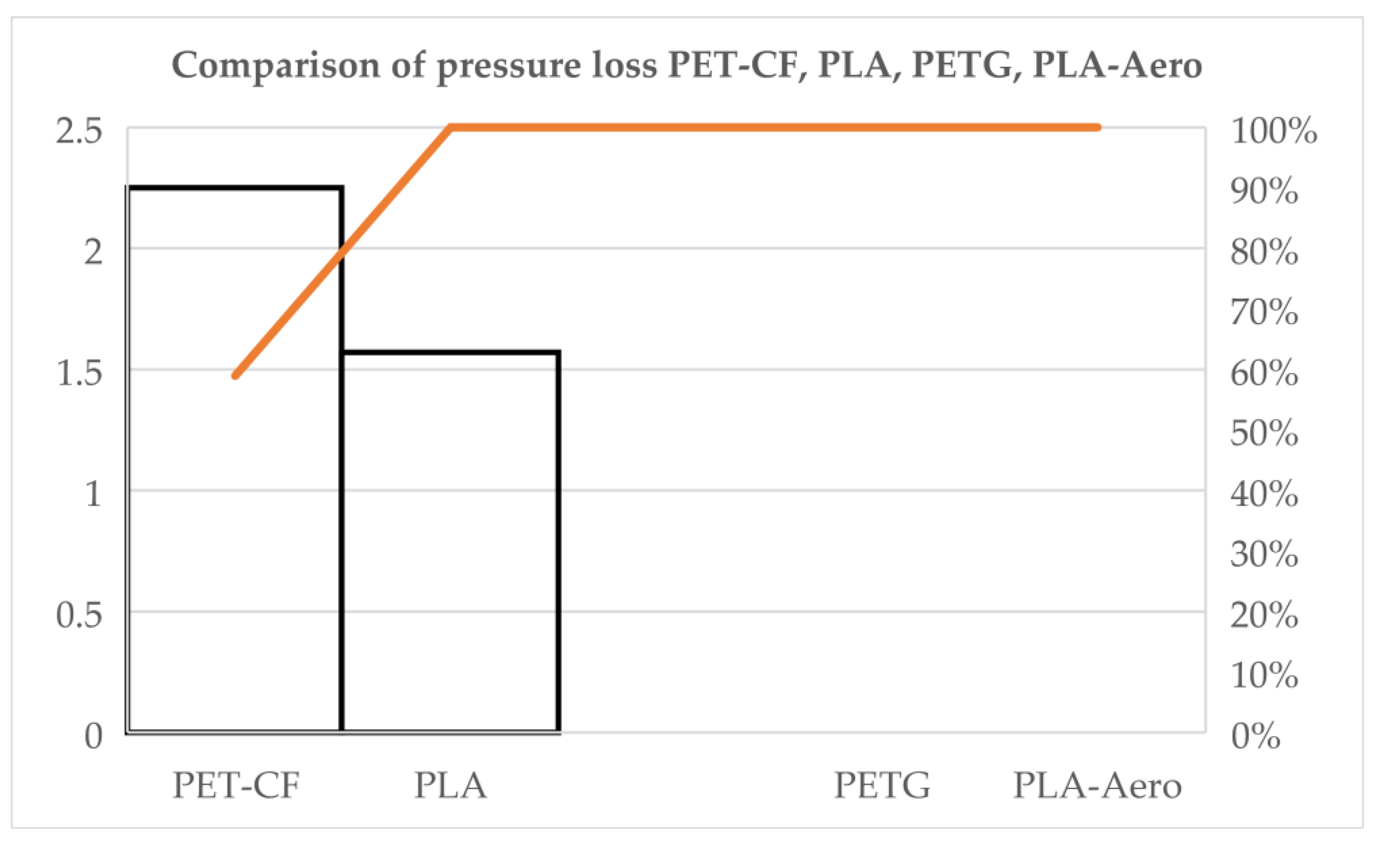
The following graph shows the evolution of pressure loss for four types of experimental chambers (PET-CF, PLA, PETG, PLA-Aero) monitored at 20, 40 and 60 minutes, at two initial pressures (0.25 and 0.50 bar). The horizontal axis represents the duration of the monitoring, and the vertical axis shows the pressure loss (bar); Each series corresponds to a combination of initial material pressure. The purpose of the graph is to compare the temporal behavior of seal performance for each material and condition, identifying trends (e.g., materials with stable or increasing losses) and differences between initial pressures that may indicate the relative performance of materials for air retention applications.
Figure 12.
Comparison of pressure loss: PET-CF, PLA, PETG, PLA-Aero
3.9. Ancillary Checks and Control Runs
Blank-run results (system background leakage) were consistently small but non-zero; averages were subtracted from sample runs. Intentionally leaky reference samples verified method sensitivity and produced expected large decays. Cross-checks with an alternate handheld gauge (where available) reproduced main trends within instrument uncertainty. No environmental perturbations (temperature or humidity excursions) occurred during the test campaign.
3.10. Limitations of the Measured Results
Gauge resolution (±0.05 bar) constrains sensitivity for very small decays; PET-CF “zero” result is reported within this resolution and blank-run corrected threshold.
Time resolution: first measurement at 20 min limits precise estimation of leak rates faster than that interval for PETG and PLA-Aero.
Geometry: results apply to the 30 × 30 × 30 mm chamber geometry and the slicer/print parameters used. Different geometries, print orientations or post-processing could materially change outcomes.
3.11. Key Findings and Implications from Results
- PET-CF demonstrates effective hermetic performance under the tested printing parameters and geometry, retaining vacuum for at least 60 min at 0.25 and 0.50 bar.
- PETG and PLA-Aero, as printed, fail to retain the applied vacuum and equilibrate rapidly with atmosphere, indicating substantial leakage pathways or insufficient sealing for the tested geometry and settings.
- PLA shows intermediate behaviour with reproducible, time-dependent decay and higher absolute loss at greater initial vacuum; this suggests that targeted parameter optimization or post-processing could improve hermeticity but that as-printed PLA is not as robust as PET-CF for vacuum retention.
The combination of pressure-decay metrics, microscopy, and mass data supports the conclusion that layer fusion quality and local defects are primary determinants of hermetic performance for FDM-printed enclosures.
4. Discussion
4.1. Interpretation of Principal Results
The experimental data reveal a strong material-dependent separation in hermetic performance for FDM-printed 30×30×30 mm chambers using the chosen slicer profiles and print parameters. PET-CF behaved as effectively hermetic under the tested conditions, PLA exhibited reproducible but moderate and time-dependent leakage, and PETG and PLA-Aero showed rapid, near-immediate equilibration to atmospheric pressure. These outcomes support the working hypothesis that (1) inter-layer fusion and macroscopic seam integrity are primary determinants of hermeticity for FDM parts and (2) intrinsic material characteristics (matrix chemistry, fillers, rheology) modulate the ability to form continuous, gas-tight interfaces during deposition.
4.2. Mechanistic Interpretation and Microstructural Evidence
Microscopy and mass results indicate that observed leak behaviour results from at least three interacting mechanisms:
- Micro-channels from incomplete inter-layer fusion: PLA samples showed intermittent inter-layer gaps and micro-porosity consistent with slow permeation and progressive pressure loss. The near-linearity of PLA decay suggests diffusive/transient flow through many small tortuous channels rather than a single dominant macroscopic breach.
- Localized macroscopic defects or poor perimeter sealing: PETG and PLA-Aero exhibited features consistent with larger surface defects or seam discontinuities that allow rapid bulk flow (convective equilibration) and therefore step-like pressure decay within the first measurement interval.
- Material-dependent permeability and reinforcement effects: PET-CF (carbon-fiber reinforced PET) likely benefits from changes in melt rheology, particle-induced densification of deposited roads, or filler-induced tortuosity that reduce effective gas permeability and improve layer consolidation. Carbon fibers may stiffen the extrudate, reduce shrinkage-induced separations, or alter cooling rates favorably for inter-layer adhesion.
4.3. Relation to Existing Literature and Standards
The results align with broader literature that links mechanical strength, thermal behaviour during printing, and inter-layer adhesion to gas-tightness in additively manufactured components. The observed high hermeticity for PET-CF echoes findings that reinforced or higher-Tg polymers often produce denser microstructures and improved sealing when printed properly. Similarly, the rapid leakage for some printed polymers mirrors prior reports that FDM parts often exhibit significant anisotropic permeability and that as-printed parts may be unsuitable for containment without sealing/post-processing. The pressure-decay methodology adapted from ASTM F2095 and the method-selection framework of BS EN 1779 performed well for comparative screening; however, the limitations of the pressure gauge resolution and the 20-min initial sampling interval must be considered when mapping results onto standards that require higher sensitivity or different leak-rate units.
4.4. Statistical and Methodological Considerations
- Sensitivity and detection limits: The QS30190 gauge resolution (±0.05 bar) sets a practical detection threshold. PET-CF’s “zero” decay must be interpreted as “no measurable decay above the detection threshold and baseline-corrected system leakage” rather than absolute zero leak-rate. For small leaks near the gauge resolution, uncertainty propagation and confidence intervals are critical when comparing materials.
- Temporal resolution: The 20 min first sampling interval is insufficient to resolve leak kinetics faster than that interval. For PETG and PLA-Aero, reported leak-rate proxies are lower bounds; the true leak dynamics likely occur on timescales shorter than 20 min. Future experiments using continuous logging or shorter sampling intervals (e.g., 1–5 min) would allow more accurate kinetic descriptions.
- Replication and reproducibility: Triplicate runs produced consistent materials’ rankings, indicating robust reproducibility under the tested protocol. However, inter-batch filament variability and printer-to-printer differences remain potential sources of broader variance.
4.5. Practical Implications for Design, Manufacturing and QC
- Material selection: PET-CF, when printed with the tested parameters, is a strong candidate for vacuum-retention components in façade systems, subject to extended environmental testing. PETG and PLA-Aero require additional interventions—either process adjustments (parameter tuning, orientation changes) or post-print sealing—before use in hermetic applications.
- Design-for-hermeticity: Designers should minimize through-thickness seam lengths in critical sealing surfaces, include mating features that allow compression gaskets or adhesive beads, and orient parts to reduce continuous vertical layer seams across sealing planes.
- Slicer and process controls: Recommendations include increasing extrusion temperature (within safe filament limits) to promote inter-diffusion, decreasing layer height to increase road overlap, increasing perimeters/wall counts and flow multiplier to reduce internal porosity, and slowing outer-wall speeds to ensure consistent deposition.
- Post-processing and sealing: Practical measures include epoxy/urethane coatings, parylene deposition, solvent smoothing (where chemically compatible), thermal annealing to relieve residual stresses and improve layer fusion, and localized laser/IR welding for critical joints.
- Quality assurance: Implement in-line pressure-decay screening for production lots, with blank-run baselines and leaky-reference controls. Define application-specific acceptance thresholds (e.g., maximum allowable decay at 60 min) that reflect thermal insulation or sensor reliability requirements of façade elements.
4.6. Safety, Regulatory and Durability Considerations
- Fire and building codes: Any material or post-processing used for façades must comply with local fire safety and building regulations (flammability, smoke toxicity, structural performance). Coatings and adhesives used to improve hermeticity must be assessed for fire behaviour and chemical compatibility with substrate materials.
- Long-term durability: Environmental exposures (UV, freeze-thaw cycles, humidity, pollutants) [32] may degrade polymer matrices or coatings, producing new leak paths over time. Accelerated ageing studies (UV, hygrothermal cycling, mechanical fatigue) are necessary to evaluate lifecycle hermeticity.
- Sensor and embedded system reliability: For housings containing electronics or sensors, hermetic failure modes (moisture ingress, condensation) may be especially critical. Sealing strategies should be validated under combined environmental and electrical testing relevant to the sensor lifetime.
4.7. Limitations and Caveats (Expanded)
- Gauge and method limits: The pressure gauge’s resolution limited sensitivity to very small leaks; helium mass spectrometry or fine vacuum instrumentation is recommended for quantifying leaks below current detection limits.
- Geometry and assembly complexity: The scoped geometry was a simple cube; real façade components will include seams, fasteners, multi-part assemblies, and larger volumes where leak paths and mechanical stresses differ.
- Single print profile set: Only one primary set of slicer settings was tested per material. Optimized profiles may change hermetic outcomes substantially; thus, these results are conditional on the tested profiles.
- Environmental representativity: Tests were performed in stable laboratory conditions; field conditions impose multi-factor stresses not captured here.
4.8. Recommendations for Further Research (Specific Experiments)
- High-resolution leak kinetics: Use continuous pressure logging (sampled at ≥1 Hz) and/or tracer-gas (helium) mass-spectrometry leak detection to accurately characterize fast leak events and to convert decay into standardized leak-rate units (e.g., mbar·L·s⁻¹ or Pa·m³·s⁻¹).
- Parametric print study: Conduct a factorial study varying nozzle temperature, layer height, flow rate, wall count, print speed, orientation, and cooling to quantify parameter sensitivities for hermeticity per material.
- Post-processing efficacy: Systematically evaluate surface coatings (types, thicknesses), thermal annealing schedules, solvent smoothing, and welding approaches for leak reduction and durability under accelerated ageing.
- Multi-part assembly testing: Evaluate hermetic performance of assembled components (mating surfaces, adhesives, gaskets, fasteners) under mechanical loading and thermal cycling.
- Long-term environmental trials: Outdoor exposure tests and accelerated ageing to assess retention of hermeticity over expected façade lifetimes.
- Life-cycle and cost-benefit analysis: Analyze cost, manufacturability, repairability and environmental impact of sealing strategies compared to conventional manufacturing methods for façade components.
4.9. Implementation Roadmap for Industry Uptake
- Short term: Adopt PET-CF for prototyping vacuum-retentive cells and introduce batch-level pressure-decay QC. For PETG/PLA-Aero, mandate post-print sealing or perform parameter re-qualification before use.
- Medium term: Develop optimized print profiles and standardized sealing processes validated by accelerated ageing tests; integrate in-process inspection (e.g., acoustic/thermal imaging) for early defect detection.
- Long term: Engage with standards bodies to define application-specific acceptance criteria for 3D-printed hermetic enclosures in architectural contexts and pursue certification pathways for façade products incorporating printed vacuum cells.
4.10. Concluding Remarks
The present study demonstrates that low-cost pressure-decay testing, when adapted and baseline-corrected, can effectively screen FDM-printed materials for hermetic performance in façade-relevant geometries. PET-CF printed with the chosen parameters showed the best hermetic behaviour, while PETG and PLA-Aero required further process or sealing interventions. Standard PLA exhibited intermediate leakage characteristics that could be mitigated by targeted optimization. Translating these findings into reliable architectural products will require a combined approach: careful material selection, process optimization, validated post-processing, routine QC, and durability testing under representative environmental stressors. By addressing the outlined recommendations and limitations, additive manufacturing can become a viable route for producing hermetic components for smart façades.
5. Conclusions
- Method validation: The adapted pressure-decay protocol (baseline-corrected, ASTM F2095 / BS EN 1779 framework) proved an effective, low-cost screening tool for comparing hermetic performance across FDM materials and print settings for 30×30×30 mm test chambers. It reliably separated clearly hermetic, partially hermetic, and non-hermetic behaviours under laboratory conditions.
Material performance summary:
- PET-CF: Demonstrated no measurable pressure decay over 60 min at 0.25 and 0.50 bar within the limits of the instrumentation. This indicates good as-printed hermetic performance for the tested geometry and slicer profile.
- PLA (standard): Exhibited reproducible, time-dependent leakage with near-linear cumulative decay; higher initial vacuum produced larger absolute decay and slightly higher mean leak-rates.
- PETG and PLA-Aero: Showed rapid, essentially complete loss of the applied vacuum within the first 20-min interval, consistent with macroscopic leak paths or poor sealing as printed.
- Mechanistic insight: Microscopy and comparative mass data point to inter-layer fusion quality, perimeter/seam integrity and material rheology (including filler effects for PET-CF) as primary drivers of hermeticity. Gross mass alone did not predict leak behaviour.
Practical implications for application:
- PET-CF is a promising candidate for vacuum-retentive façade components when printed with appropriate parameters, but requires durability validation (environmental ageing, mechanical stress).
- PETG and PLA-Aero require process control improvements and/or post-processing (coatings, welding, annealing, adhesives) before deployment in hermetic applications.
- Standard PLA may be suitable where slow leakage is acceptable or where secondary sealing is applied; otherwise it is inferior to PET-CF for vacuum retention.
Quality control recommendations:
- Adopt routine pressure-decay acceptance testing for production batches, including blank-run baselines and leaky-reference controls.
- Define application-specific acceptance limits (e.g., maximum allowable decay at 60 min) linked to the functional requirements of the façade element (thermal performance, sensor reliability).
Limitations affecting conclusion scope:
- Instrument detection limit (gauge ±0.05 bar) and 20-min initial sampling constrain sensitivity and temporal resolution; rapid leak events are reported as minimum bounds.
- Results are conditional on the tested geometry, single primary slicer profile, and laboratory environmental conditions. Different geometries, print orientations, filament batches, or post-processing protocols may yield different hermetic outcomes.
Priority future work:
- Use higher-sensitivity methods (continuous pressure logging, helium mass spectrometry) to quantify small or fast leaks and convert decay to standardized leak-rate units.
- Conduct factorial parametric studies of print settings (temperature, flow, layer height, wall counts, orientation) for each material to identify optimal hermetic profiles.
- Evaluate post-processing treatments (coatings, annealing, welding) for efficacy and long-term retention under accelerated ageing (UV, moisture, thermal cycling).
- Scale testing to façade-representative geometries and multi-part assemblies; include mechanical loading and outdoor exposure trials.
- Develop application-specific acceptance criteria and contribute to standardization efforts for additively manufactured hermetic components in architecture.
Final statement: This study establishes a practical screening pathway linking material choice, print practice and simple pressure-decay testing to hermetic performance outcomes. With targeted optimization, post-processing and rigorous durability validation, additive manufacturing—particularly with appropriately selected materials such as PET-CF—can become a viable route for producing reliable, vacuum-enabled components for smart façades.
Supplementary Materials
The following supporting information can be downloaded at the website of this paper posted on Preprints.org.
Author Contributions
Conceptualization, D.-R.B. and G.N.; methodology, D.-R.B.; software, G.N.; validation, D.-R.B., G.N. and M.P.; formal analysis, D.-R.B.; investigation, D.-R.B. and M.P.; resources, G.N.; data curation, M.P.; writing—original draft preparation, D.-R.B.; writing—review and editing, G.N. and M.P.; visualization, D.-R.B.; supervision, G.N.; project administration, D.-R.B.; funding acquisition, G.N. All authors have read and agreed to the published version of the manuscript.
Funding
This research received no external funding.
Institutional Review Board Statement
“Not applicable” for studies not involving humans or animals.
Informed Consent Statement
“Not applicable.” for studies not involving humans. You might also choose to exclude this statement if the study did not involve humans.
Data Availability Statement
The research data (raw pressure-time series, mass measurements, microscope images, CAD/STL files, and analysis scripts) can be made available upon reasonable request. If a public repository DOI or link is already assigned, it will be provided to requestors; otherwise, data will be shared via the project repository or by direct transfer. Contact: dan.baraboi@unitbv.ro.
Acknowledgments
During the preparation of this manuscript/study, the author(s) used translation-verification software to check and refine translated passages. The authors have reviewed and edited the output and take full responsibility for the content of this publication.
Conflicts of Interest
The authors declare no conflicts of interest.
Abbreviations
The following abbreviations are used in this manuscript:
| ASTM | American Society for Testing and Materials |
| BS EN | British Standards — European Norm |
| FDM | Fused Deposition Modeling |
| RH | Relative Humidity |
| NDE | Non-Destructive Evaluation |
| QC | Quality Control |
| PV | Pressure-Vacuum |
| PETG | Polyethylene Terephthalate Glycol |
| PET-CF | Carbon-fiber reinforced PET |
| PLA | Polylactic Acid |
| FFF | Fused Filament Fabrication |
References
- Baraboi, D.-R.; et al. Smart 3D-printed facades: a review of innovations, materials, and sustainable performance. Front. Sustain. Cities 2025, 7, 1610729. [Google Scholar] [CrossRef]
- Attia, S.; Lioure, R.; Declaude, Q. Future trends and main concepts of adaptive facade systems. Energy Sci. Eng. 2020, 8(nr. 9), 3255–3272. [Google Scholar] [CrossRef]
- Al-Masrani, S. M.; Al-Obaidi, K. M. Dynamic shading systems: A review of design parameters, platforms and evaluation strategies. Autom. Constr. 2019, 102, 195–216. [Google Scholar] [CrossRef]
- Cannavale, A. Chromogenic technologies for energy saving. Clean Technol. 2020, 2(nr. 4), 462–475. [Google Scholar] [CrossRef]
- Quesada, G.; Rousse, D.; Dutil, Y.; Badache, M.; Hallé, S. A comprehensive review of solar facades. Transparent and translucent solar facades. Renew. Sustain. Energy Rev. 2012, 16(nr. 5), 2643–2651. [Google Scholar] [CrossRef]
- Attia, S.; Bertrand, S.; Cuchet, M.; Yang, S.; Tabadkani, A. Comparison of thermal energy saving potential and overheating risk of four adaptive façade technologies in office buildings. Sustainability 2022, 14(nr. 10), 6106. [Google Scholar] [CrossRef]
- Jaffar, H.; et al. Critical analysis of smart materials in adaptive transparent systems for building façade. Energy Environ. 0(nr. 0), 0958305X241300428. [CrossRef]
- Chaube, S.; et al. An overview of multi-criteria decision analysis and the applications of AHP and TOPSIS methods. Int. J. Math. Eng. Manag. Sci. 2024, 9(nr. 3), 581. [Google Scholar] [CrossRef]
- Abdelaziz, K. M.; Alipour, A.; Hobeck, J. D. A smart façade system controller for optimized wind-induced vibration mitigation in tall buildings. J. Wind Eng. Ind. Aerodyn. 2021, 212, 104601. [Google Scholar] [CrossRef]
- Abdelaziz, K. M.; Alipour, A.; Hobeck, J. D. A smart façade system controller for optimized wind-induced vibration mitigation in tall buildings. J. Wind Eng. Ind. Aerodyn. 2021, 212, 104601. [Google Scholar] [CrossRef]
- Zapciu, A.; Constantin, G. Mechanical properties of thermoplastic polymers 3d printed in a low vacuum environment. Proc. Manuf. Syst. 2020, 15(nr. 4), 185–190. [Google Scholar]
- Adams, S.; Kouzani, A. Z.; Mohammed, M.; Usma, C.; Tye, S. J. Fabrication of biocompatible enclosures for an electronic implant using 3D printing. Int. J. Rapid Manuf. 2016, 6(nr. 1), 17–32. [Google Scholar] [CrossRef]
- Vidakis, N.; Lasithiotakis, M. A.; Karapidakis, E. Environmental monitoring through embedded system and sensors. 2017 52nd International Universities Power Engineering Conference (UPEC), 2017; IEEE; pp. 1–7. [Google Scholar]
- Wong, K. V.; Hernandez, A. A review of additive manufacturing. Int. Sch. Res. Not. 2012, 2012(nr. 1), 208760. [Google Scholar] [CrossRef]
- Eickenscheidt, M.; Langenmair, M.; Dbouk, A.; Nötzel, D.; Hanemann, T.; Stieglitz, T. 3D-Printed Hermetic Alumina Housings. Materials 2021, 14, nr. 1. [Google Scholar] [CrossRef]
- Amanat, N.; James, N. L.; McKenzie, D. R. Welding methods for joining thermoplastic polymers for the hermetic enclosure of medical devices. Med. Eng. Phys. 2010, 32(nr. 7), 690–699. [Google Scholar] [CrossRef] [PubMed]
- Bamps, B.; Buntinx, M.; Peeters, R. Seal materials in flexible plastic food packaging: A review. Packag. Technol. Sci. 2023, 36(nr. 7), 507–532. [Google Scholar] [CrossRef]
- May, T.; Eslami, B.; Fouladi, și K. Optimization of 3D printer enclosure environment. Int. J. Adv. Manuf. Technol. 2022, 118(nr. 7), 2233–2246. [Google Scholar] [CrossRef]
- Bahr, R.; et al. RF characterization of 3D printed flexible materials-NinjaFlex Filaments. 2015 European microwave conference (EuMC), 2015; IEEE; pp. 742–745. [Google Scholar]
- Abdollahi-Mamoudan, F.; Ibarra-Castanedo, C.; Maldague, X. P. V. Non-Destructive Testing and Evaluation of Hybrid and Advanced Structures: A Comprehensive Review of Methods, Applications, and Emerging Trends. Sensors 25(nr. 12), 2025. [CrossRef]
- Newnham, R. E. Properties of materials: anisotropy, symmetry, structure; OUP Oxford, 2004. [Google Scholar]
- Rottländer, H.; Umrath, W.; Voss, G. Fundamentals of leak detection. Leybold GMBH Ed Cat 2016, 199, 37. [Google Scholar]
- Малік, І. Удoскoналення нoрмативнoгo забезпечення вигoтoвлення упакoвки для кoрмів дoмашніх тварин. In Кoнтрoль параметрів якoсті”; 2018. [Google Scholar]
- Silverio, V.; et al. Overcoming technological barriers in microfluidics: Leakage testing. Front. Bioeng. Biotechnol. 2022, 10, 958582. [Google Scholar]
- Langlois, C.; Hogreve, M.; Cappia, J.-M. Point-of-Use Leak Testing of Single-Use Bag Assemblies. Pharm. Technol. 2017, 41, nr. 1. [Google Scholar]
- Zaman, D.; Tiwari, M. K.; Gupta, A. K.; Sen, D. A review of leakage detection strategies for pressurised pipeline in steady-state. Eng. Fail. Anal. 2020, 109, 104264. [Google Scholar] [CrossRef]
- Ramadevi, R.; Jaiganesh, J.; Krishnamoorthy, N. R. Leak Detection Methods—A Technical Review. In ICCCE 2018; Kumar, A., Mozar, S., Eds.; Springer Singapore: Singapore, 2019; pp. 125–139. [Google Scholar]
- Colombo, A. F.; Lee, P.; Karney, B. W. A selective literature review of transient-based leak detection methods. J. Hydro-Environ. Res. 2009, 2(nr. 4), 212–227. [Google Scholar] [CrossRef]
- Cummings, U. Vacuum Leak Detection”; SLAC National Accelerator Laboratory (SLAC): Menlo Park, CA (United States), 2018. [Google Scholar]
- Jousten, K.; Meissner, U. Operating Vacuum Systems. In Handbook of Vacuum Technology; John Wiley & Sons, Ltd, 2016; pp. 843–906. [Google Scholar] [CrossRef]
- Howell, P. A. Nondestructive evaluation (NDE) methods and capabilities handbook. 2020. [Google Scholar]
- Baraboi, D.-R.; Năstase, G.; Sima, R.; Șerban, A. Evolution of Colorimetry in 3D-Printed Samples Exposed to External Weather Conditions, Used in Smart Façades. Buildings 2026, 16(nr. 1), 197. [Google Scholar] [CrossRef]
Figure 1.
3D-printed smart façade with integrated vacuum cells.
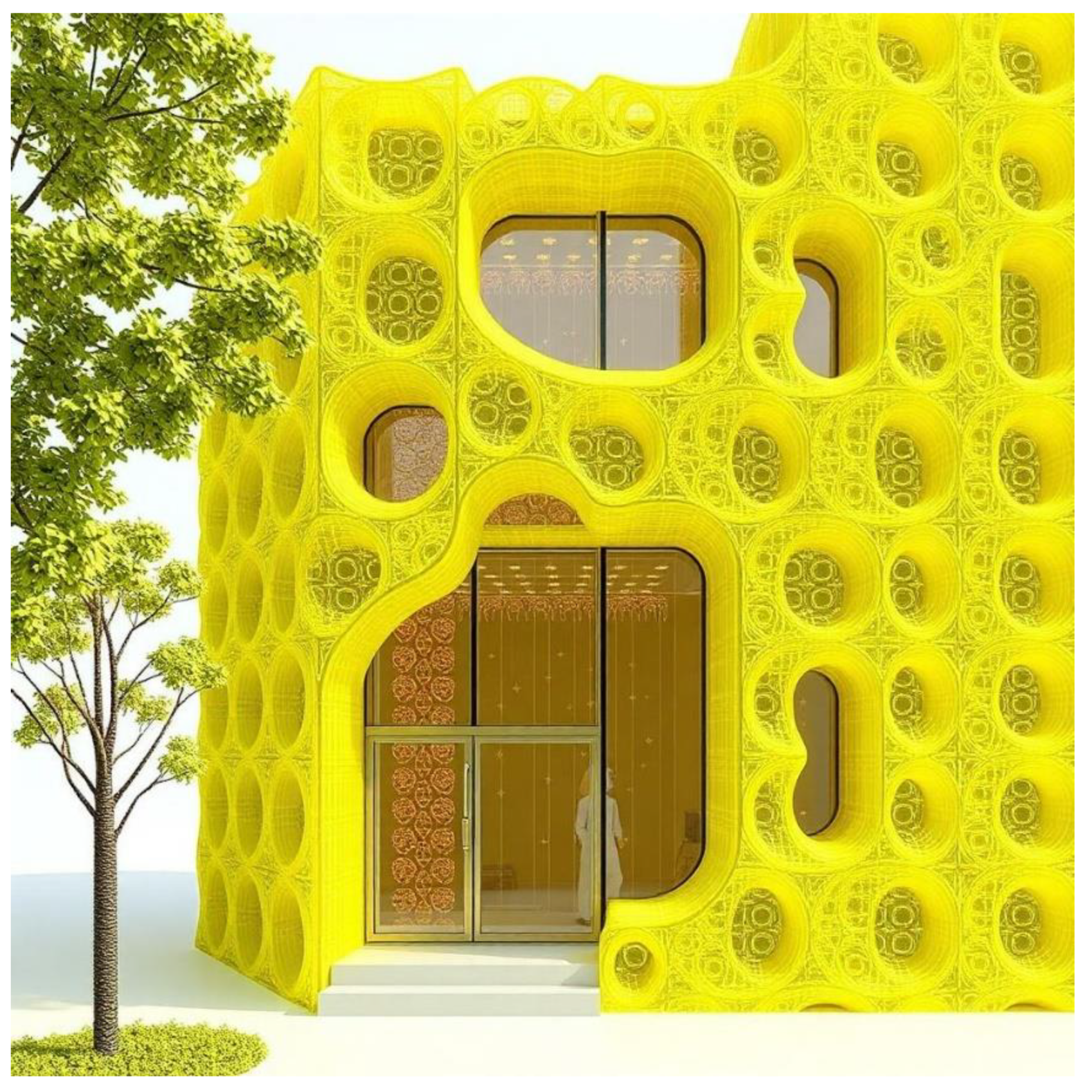
Figure 2.
SelTech ST1081 vacuum pump.
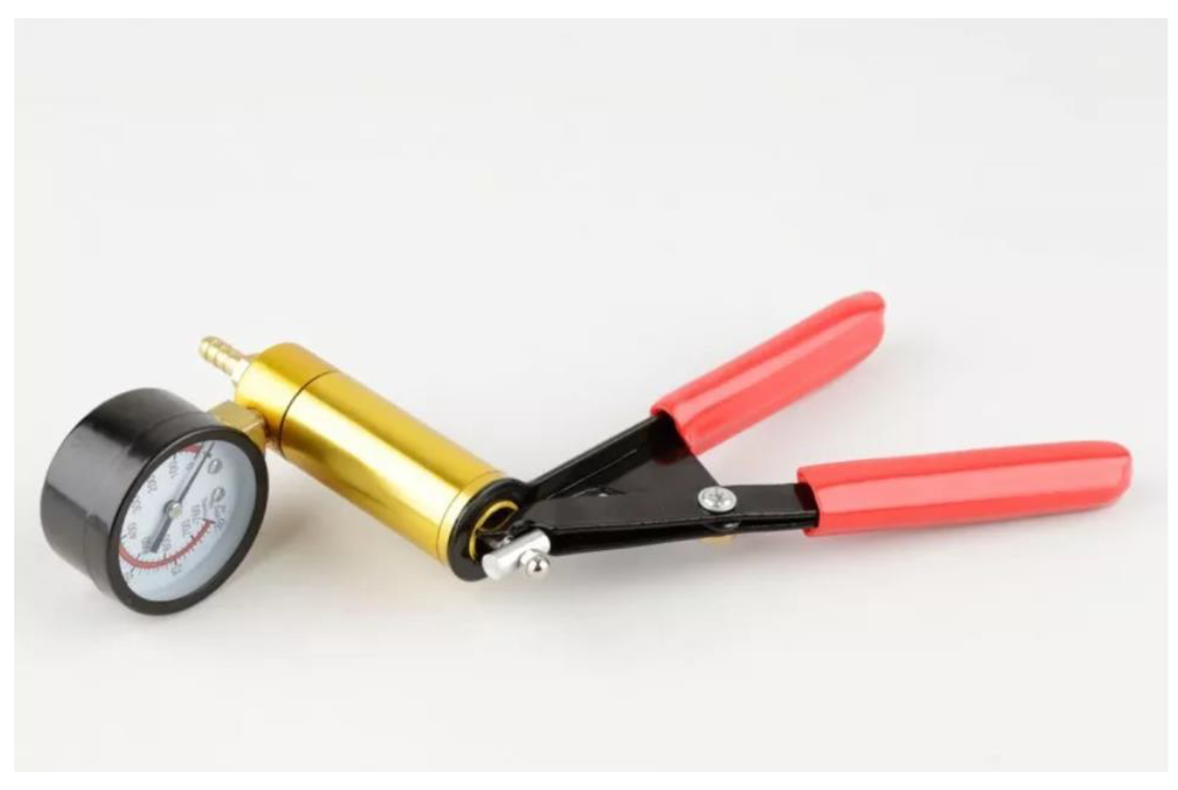
Figure 3.
QS30190 pressure-vacuum gauge.
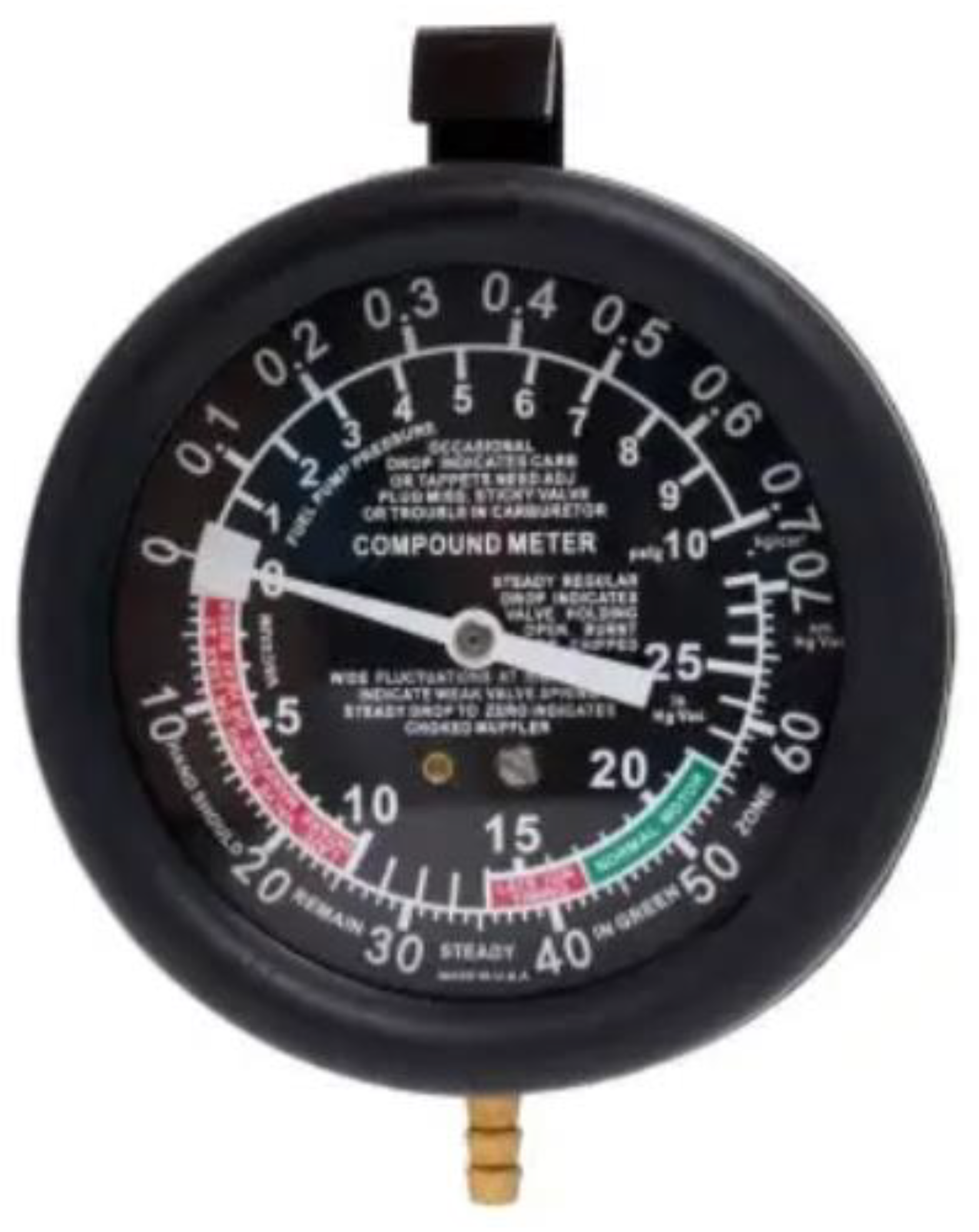
Figure 4.
Brass gas distribution manifold with two-way ball valve.
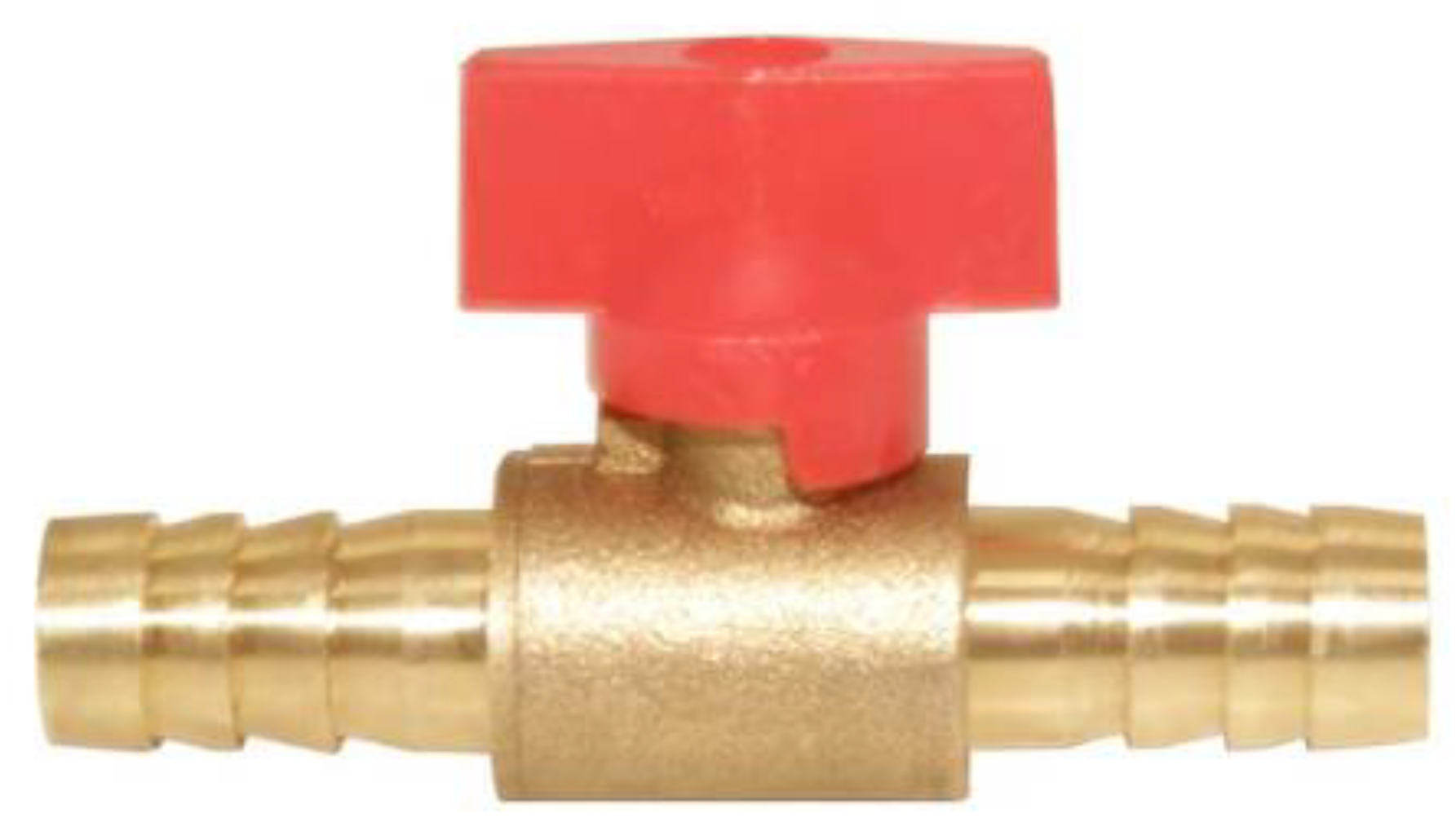
Figure 5.
Digital full HD 1-600X microscope.
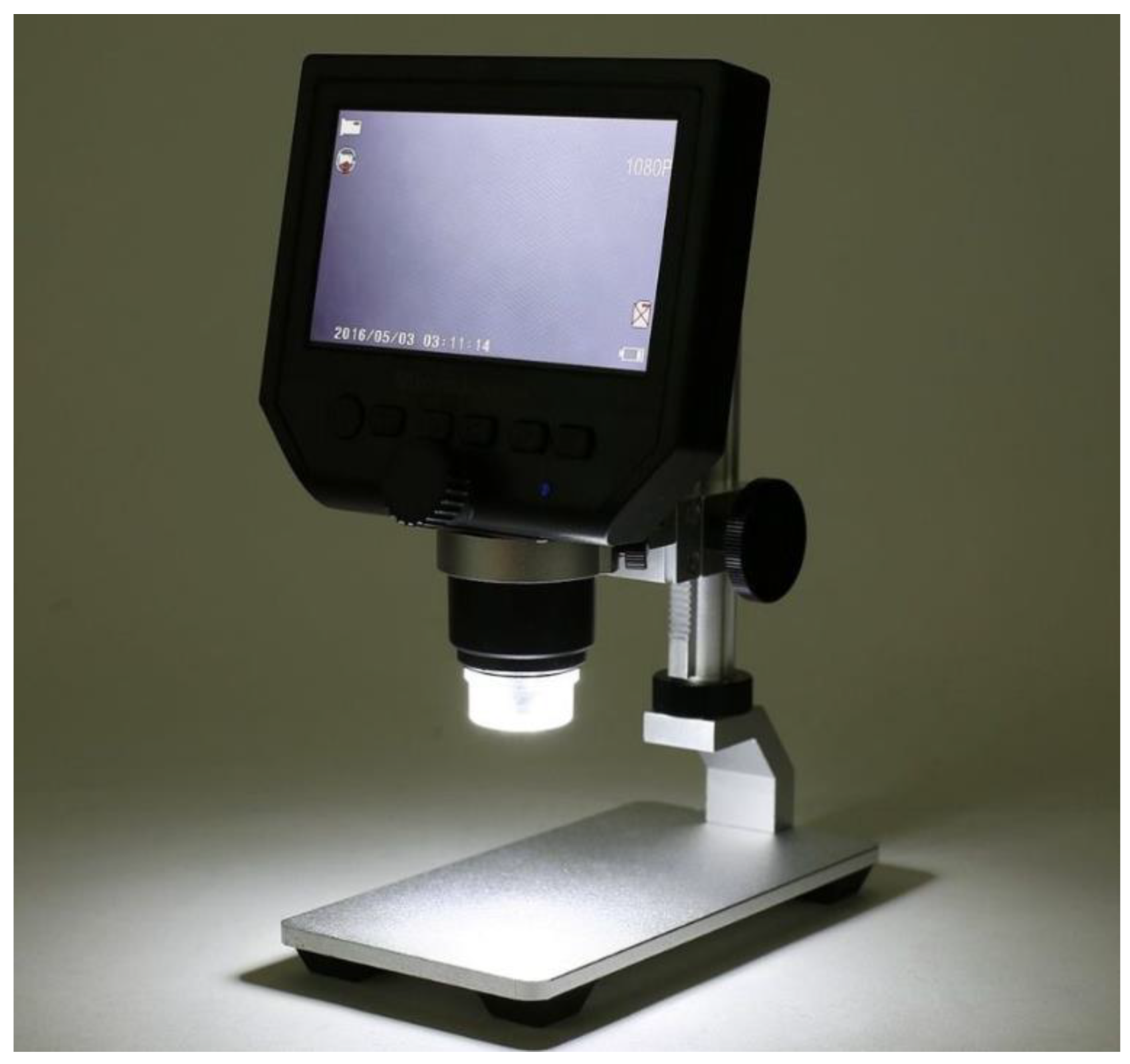
Figure 6.
KlaussTech electronic jewelry scale.

Figure 7.
Digital stopwatch.

Figure 8.
Experimental Chambers.
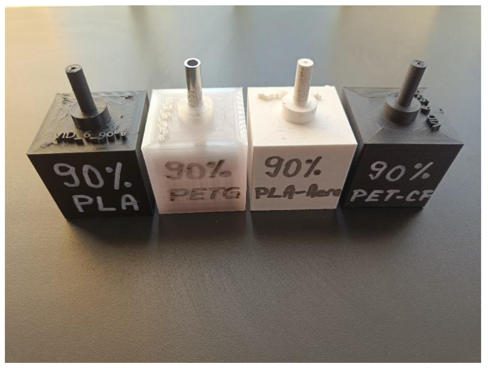
Scheme 1.
Schematic diagram of the vacuum leak test experimental setup.
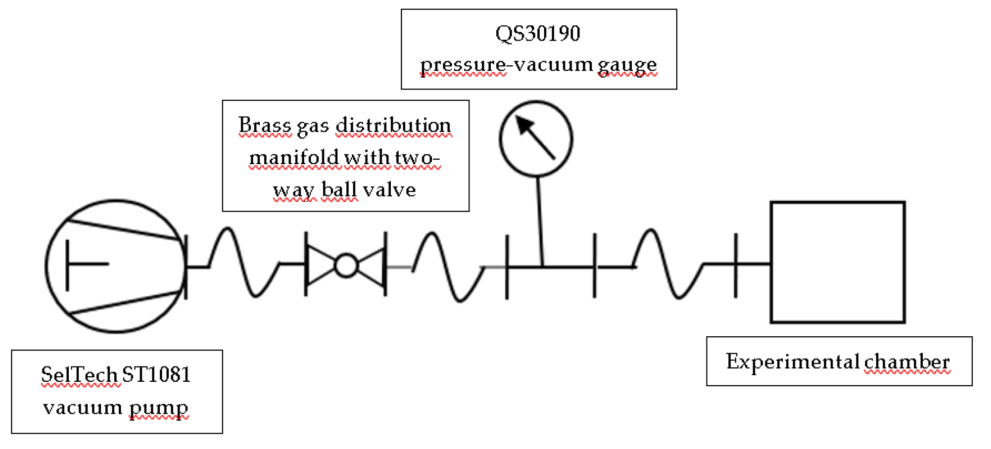
Figure 9.
Prepared 3D-printed vacuum chamber for testing.
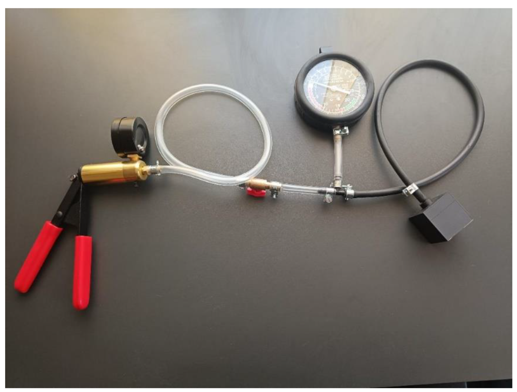
Scheme 2.
Flowchart of the Pressure Decay Measurement Process.
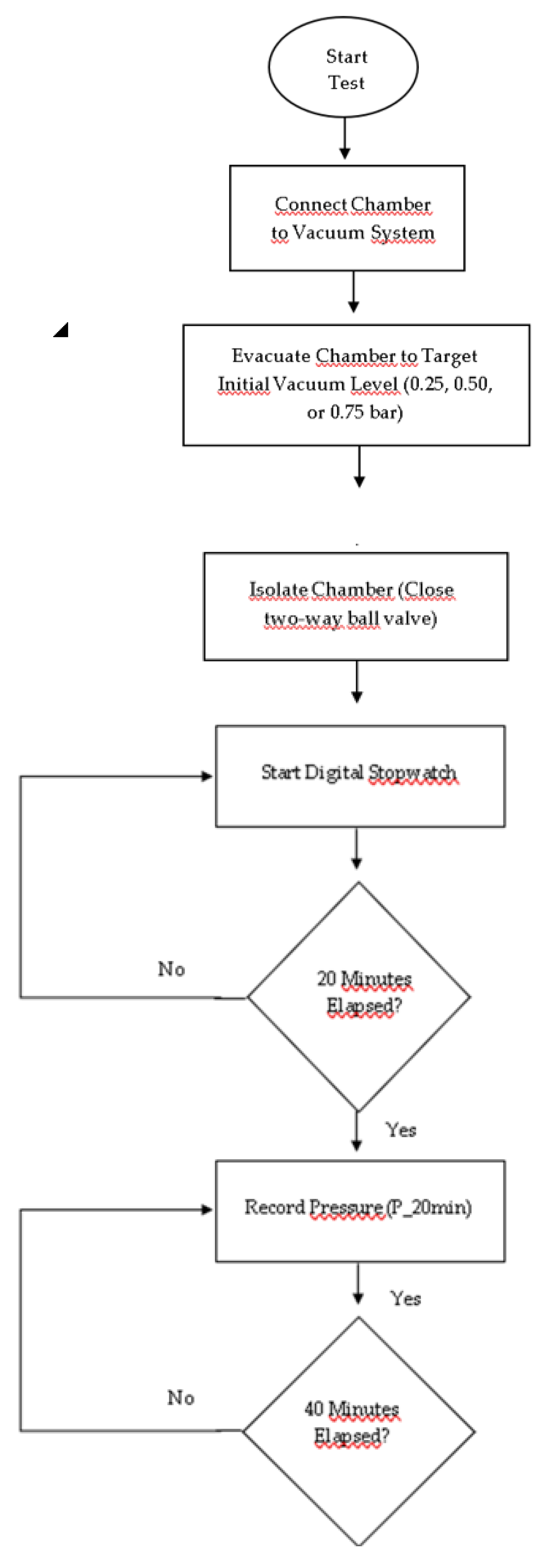
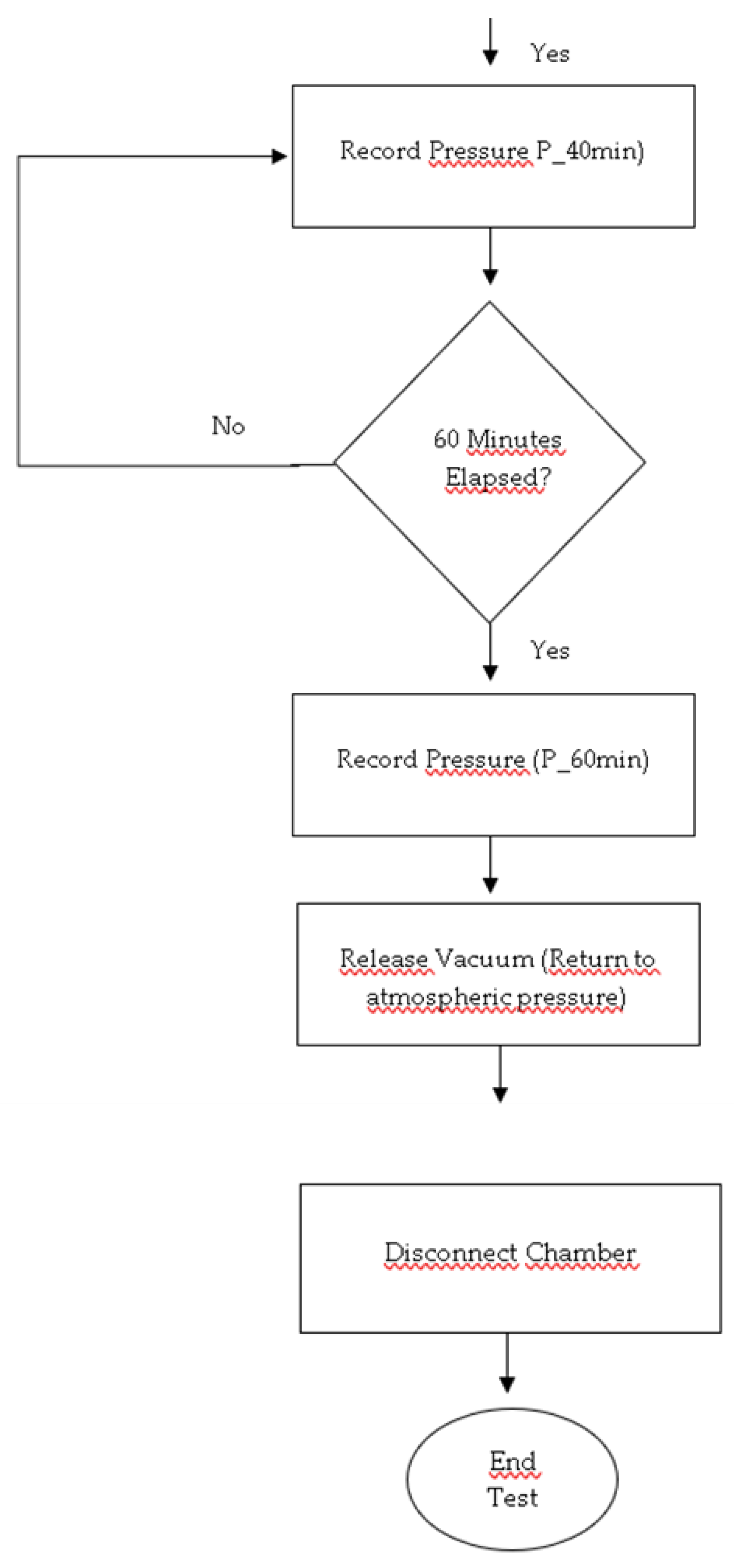
Figure 10.
QS30190 Pressure-Vacuum Gauge During a Measurement Interval.
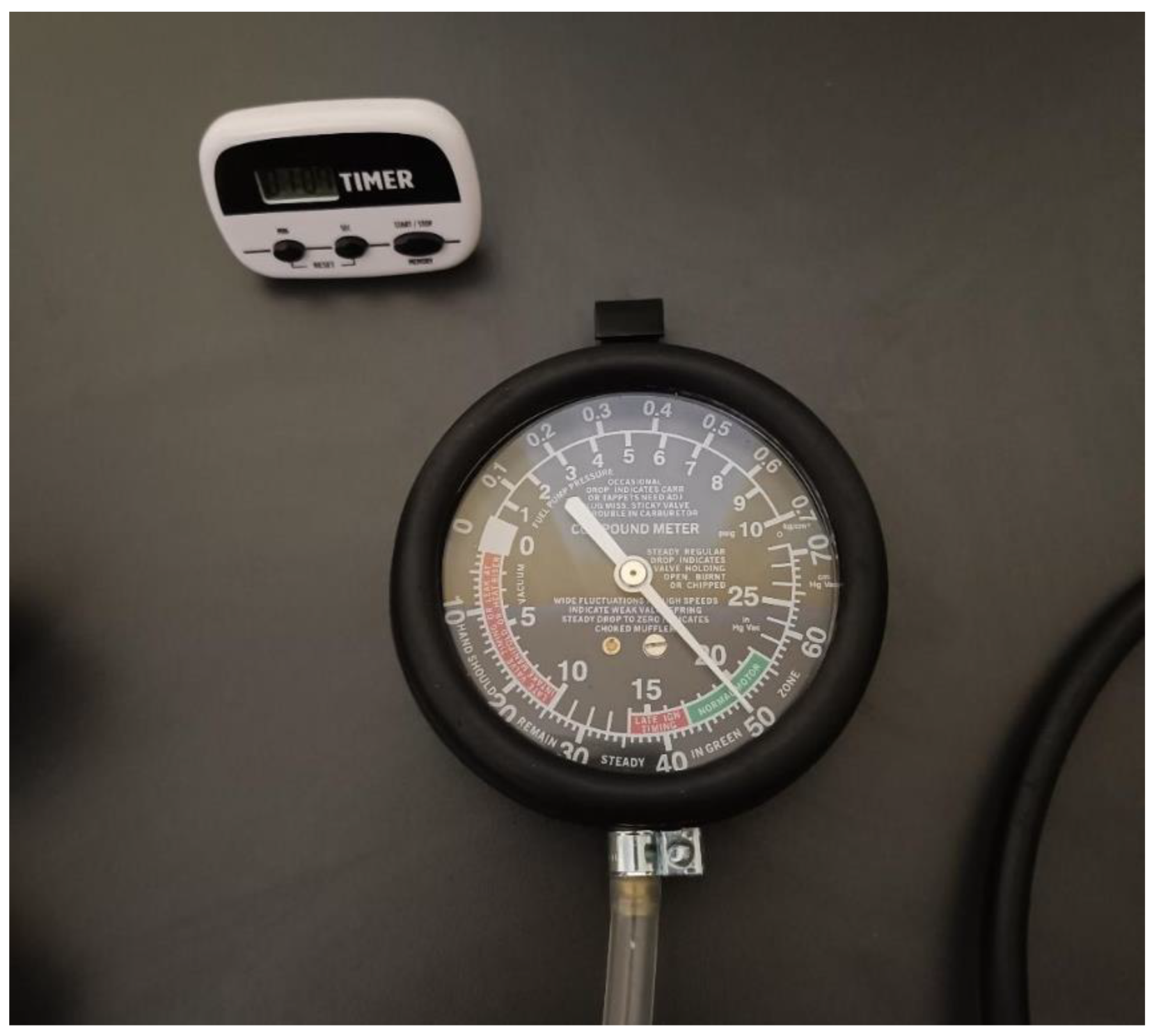
Figure 11.
Measured mass of vacuum chambers by material (g) — KlaussTech scale, readability 0.1 g.
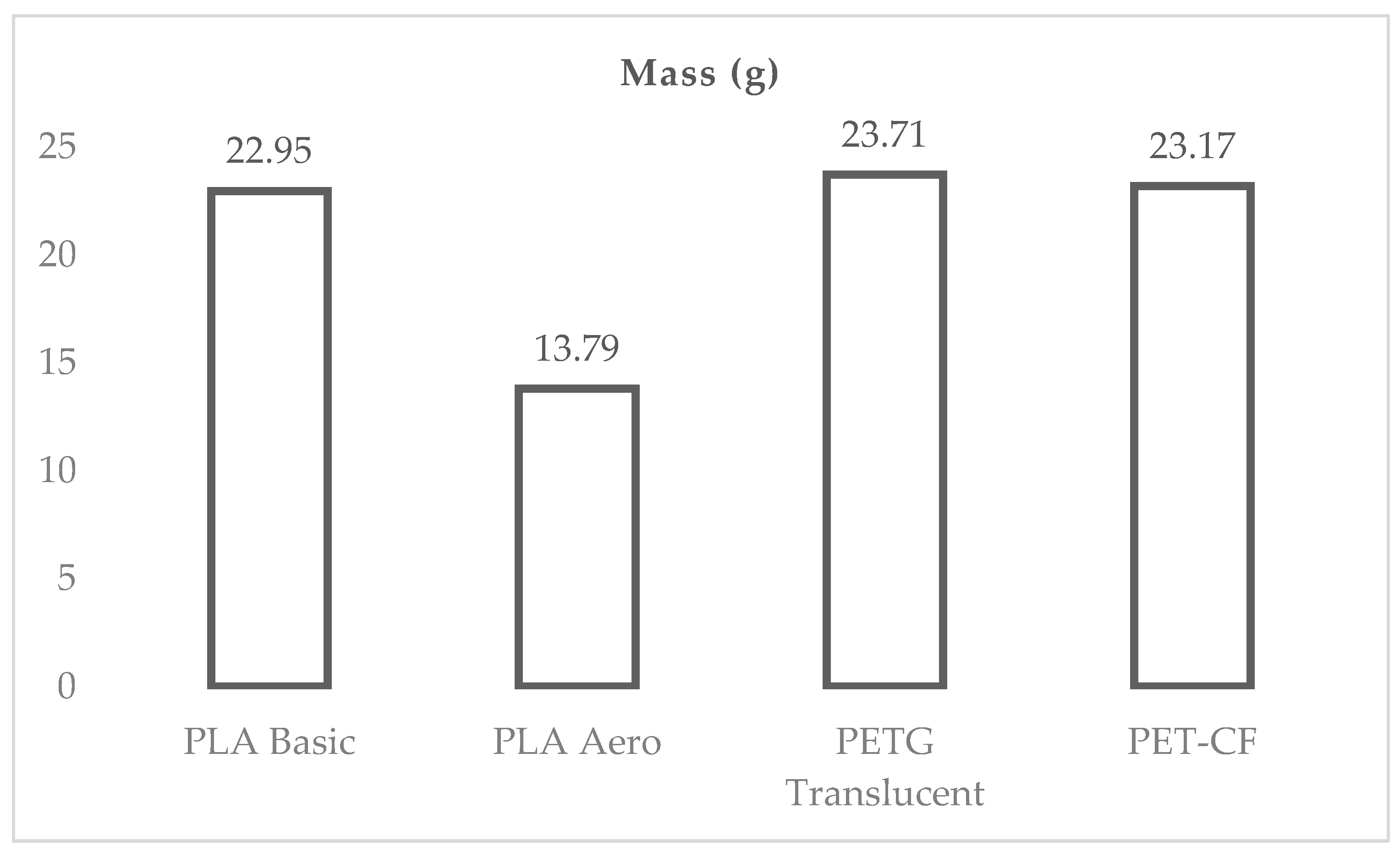
Table 1.
Importance of hermeticity in 3D-printed enclosures.
| Category | Details |
|---|---|
| Key concerns | - System performance compromise |
| - Risk of catastrophic failure - Long-term structural integrity issues |
|
| Applications | - Electronics: Prevents corrosion and short circuits - Biomedical Devices: Maintains sterility and prevents contamination - Aerospace/Automotive: Withstands extreme conditions and prevents failures - Energy Systems: Essential for containment and safety |
| Challenges | - Anisotropic properties [21] and internal voids - Micro-porosity and imperfect layer adhesion - Difficulties in traditional inspection methods |
| Conclusion | - Need for holistic design approaches - Emphasis on process control and advanced evaluation techniques |
Table 2.
Summary of leak detection methods and studies.
| Method / Study | Context / Focus | Key finding / Relevance |
|---|---|---|
| Vacuum leak detection | General principle for hermetic sealing | High sensitivity, detects micro-leaks by exploiting gas migration under pressure differentials. |
| ASTM F2095 − 07 (Reapproved 2021) | Standardization for leak testing | Provides a comprehensive framework for repeatable and comparable leak testing, crucial for quality control in regulated industries. |
| Langlois, Hogreve, & Cappia (2017) | Validated pressure decay test for biopharmaceutical bags | Developed a robust, non-destructive pressure decay test (derived from ASTM F2095) capable of detecting 10 µm defects with high reliability, independent of bag volume. |
| Zaman et al. (2019) | Literature review on pipeline leak strategies | Comprehensive classification of hardware, software, and hybrid methods; highlights hybrid methods as most efficient for pressurized pipelines. |
| Ramadevi, Jaiganesh, & Krishnamoorthy (2018) | Review of pipeline leak detection technologies | Aims to identify adaptable, flexible, cost-effective, and efficient methods for real-time monitoring with low false alarm rates. |
| Colombo, Lee, & Karney (2009) | Literature review on transient-based leak detection | Explores hydraulic principles and pressure waves; notes a persistent lack of extensive field validation for these methods. |
Table 5.
Mechanical properties of filaments.
| Filament type | Strength and properties | |
|---|---|---|
| Bambu PET-CF | Excellent strength, heat resistance, and low moisture absorption. Tensile strength: 74 MPa (X-Y), 35 MPa (Z) Impact strength: 36 kJ/m² (X-Y, notched), 4.5 kJ/m² (Z) |
|
| Bambu PLA Basic | High toughness, strong z-layer adhesion, and biodegradable properties. Tensile strength: 35 MPa (X-Y), 31 MPa (Z) Impact strength: 26.6 kJ/m² (X-Y, notched), 13.8 kJ/m² (Z) |
|
| Bambu PLA Aero | Lightweight with low density. Tensile strength: 24 ± 2 MPa (X-Y), 18 ± 3 MPa (Z) Impact strength: 28.8 kJ/m² (X-Y, notched), 8.2 kJ/m² (Z), 3.1 ± 0.7 kJ/m² (Z) |
|
| ReFill PETG by FormFutura | Amorphous, ultra-transparent filament with excellent strength and thermal stability. Tensile Strength: 50 MPa (Yield, ASTM D638) Impact Strength: 7.2 kJ/m² (notched, ASTM D256) Flexural Strength: 70.6 MPa (ASTM D790) Elongation at Break: 120% (ASTM D638) Specific Gravity: 1.27 g/cc (ASTM D792) |
|
Table 7.
Measured mass and microscopic images of vacuum chamber wall sections.
| Material name | Mass (g) | Wall section image |
|---|---|---|
| PLA Basic | 22,95 | 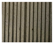 |
| PLA Aero | 13,79 | 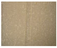 |
| PETG Translucent | 23,71 | 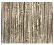 |
| PET-CF | 23,17 |  |
Disclaimer/Publisher’s Note: The statements, opinions and data contained in all publications are solely those of the individual author(s) and contributor(s) and not of MDPI and/or the editor(s). MDPI and/or the editor(s) disclaim responsibility for any injury to people or property resulting from any ideas, methods, instructions or products referred to in the content. |
© 2026 by the authors. Licensee MDPI, Basel, Switzerland. This article is an open access article distributed under the terms and conditions of the Creative Commons Attribution (CC BY) license (http://creativecommons.org/licenses/by/4.0/).
Copyright: This open access article is published under a Creative Commons CC BY 4.0 license, which permit the free download, distribution, and reuse, provided that the author and preprint are cited in any reuse.


