Submitted:
26 January 2026
Posted:
27 January 2026
You are already at the latest version
Abstract
A comprehensive review of Dual Gradient Drilling (DGD) and Riserless Mud Recovery (RMR) technology was conducted. Deepwater and ultra-deepwater drilling operations were confronted with significant challenges, primarily characterized by narrow formation pressure windows and the physical limitations of conventional riser systems. DGD was proposed as a theoretical framework to address these issues by fundamentally reshaping the wellbore pressure profile. The RMR system, recognized as a mature and commercially successful implementation of the DGD concept, enabled closed-loop recovery of drilling fluid and precise pressure control without employing a conventional riser. This paper systematically reviewed the principles, historical development, global applications, and future challenges associated with this technology. First, the core mechanism of DGD was elucidated, which involved establishing a "virtual wellhead" on the seabed to achieve segmented pressure control, along with the technical architecture and operational workflow of the RMR system. Second, the technological evolution was traced, from its initial conceptualization and subsequent joint industry research and development to its commercialization and expansion into deepwater operations. The review summarized the application outcomes in major global deepwater basins, highlighting its effectiveness in mitigating shallow geohazards, optimizing wellbore architecture, and meeting stringent environmental regulations. Furthermore, the challenges faced during the technology's advancement towards ultra-deepwater environments and intelligent development were analyzed, including issues pertaining to critical equipment reliability, intelligent control systems, adaptability to extreme environments, and cost-effectiveness. Finally, its potential application in emerging fields such as scientific ocean drilling and natural gas hydrate exploitation was explored. This review aimed to provide a systematic reference to support the advancement of deepwater drilling technologies.
Keywords:
Dual Gradient Drilling
; Riserless Mud Recovery
; deepwater drilling
; pressure control
1. Introduction: Common Challenges in Deepwater Drilling and the Driving Forces for Technological Innovation
The strategic advancement into deepwater and ultra-deepwater domains was recognized as a critical pathway. This path was pursued for both securing energy supply and advancing earth science exploration. Marine hydrocarbon resources are known to be abundant. However, deepwater drilling operations were confronted with a series of severe challenges. These included harsh environmental conditions, narrow formation pressure windows, poor wellbore stability, and the requirement for additional casing strings [1,2,3,4]. For the oil and gas industry, deepwater regions have long been regarded as holding immense potential. This potential was seen as crucial for future global resource reserves. Consequently, intense international competition was driven by this prospect. Continuous technological evolution was also stimulated. Concurrently, the scientific community, exemplified by the Integrated Ocean Drilling Program (IODP), was dedicated to a specific goal. The retrieval of geological records from deepwater areas was pursued. The targeted water depths for such scientific endeavors often exceeded those of routine industrial operations. A common and formidable reality was faced by both industrial and scientific endeavors. It was acknowledged that technical challenges escalated proportionally with increasing water depth.
The technical bottlenecks posed by deepwater and ultra-deepwater environments were multidimensional and interrelated. Among them, the most critical constraint was identified as the "narrow formation pressure operating window." Shallow formations in deepwater settings were often under-compacted. They exhibited low mechanical strength. This resulted in an extremely narrow safety margin between formation pore pressure and fracture pressure. Conventional drilling practices relied on the hydrostatic pressure from a single-density drilling fluid column within a marine riser system. Precise and stable pressure control within this critical window was difficult to achieve. Consequently, fluid influx (kicks), losses, or wellbore collapse were frequently encountered. Secondly, the "physical and economic limits of traditional riser systems" presented a major challenge. In conventional offshore drilling, the riser served as the key equipment for establishing a drilling fluid return path. However, as operational water depths increased, a corresponding increase in riser length introduced a series of derivative problems [1,2]. Conventional steel riser systems possessed significant weight. They required complex tensioning and compensation. Dynamic response issues related to their length were also noted. Therefore, a practical upper limit for their safe and economical operation existed [5]. The deployment of long risers led to high capital and operational costs. Furthermore, stringent demands were placed on the drilling vessel's variable load capacity, deck space, and dynamic positioning system [1,2]. Additionally, during the initial "open-hole" drilling phase prior to riser installation, a standard "pump-and-dump" practice was often employed. Drilling mud and cuttings were discharged directly into the ocean. This practice was identified as causing significant marine environmental pollution. It also represented a substantial waste of valuable drilling fluid [6].
To systematically overcome these inherent limitations, a shift in technological paradigm was pursued by both industry and academia. Among the proposed innovations, Dual Gradient Drilling (DGD) was introduced as an unconventional drilling technique. It was designed to control bottomhole pressure by altering the pressure gradient within the wellbore annulus. This objective was achieved through methods such as the utilization of subsea pumps or the modification of annular fluid density [7,8]. Consequently, DGD provided a theoretical framework for addressing the core challenges.
The Riserless Mud Recovery (RMR) system emerged as one of the most mature and commercially successful engineering implementations of the DGD concept. It effectively solved the problems associated with mud handling and recovery during the open-hole drilling phase. A closed-loop, recoverable drilling fluid circulation system was established without the use of a conventional riser [9,10,11]. Several key benefits were realized through this approach. Shallow geohazards, such as water flows, were mitigated. The marine environment was better protected. Furthermore, the wellbore architecture could be optimized. This optimization often resulted in a reduction of required casing strings. Therefore, major challenges in deepwater drilling were addressed [12,13,14,15]. As a result, RMR technology has been established as a key and widely utilized technology in deepwater oil and gas drilling. This is particularly true for challenging shallow hole sections.
2. The DGD System: From Principles to Historical Evolution
2.1. Core Principles of DGD
DGD was defined by the International Association of Drilling Contractors (IADC) as "the use of two or more pressure gradients within selected sections of the wellbore to manage the pressure profile" [16]. In essence, the single, linear hydrostatic pressure gradient from the bottom of the well to the sea surface, characteristic of conventional drilling, was replaced. It was substituted by a segmented, multi-gradient structure. This structure was better matched to complex formation pressure profiles.
As illustrated in Figure 1, a key distinction was observed when comparing the DGD configuration (Figure 1B) to conventional riser drilling (Figure 1C) and riserless drilling (Figure 1A). In the DGD configuration, a pressure control node was established on the seabed. The annular space from the sea surface down to this node was filled with seawater or a low-density fluid. This created the first, gentler pressure gradient. From this node down to the bottom of the well, weighted drilling mud was circulated in the annulus. This established a second, steeper pressure gradient.
The physical effect was equivalent to virtually relocating the hydrostatic pressure reference point of the drilling operation from the sea surface to the seabed. Consequently, the excess hydrostatic head acting on the open-hole section was significantly reduced. This mechanism provided a revolutionary advantage: the drilling window was effectively widened (Figure 2). The lengthy column of drilling mud hydrostatic pressure was eliminated. Therefore, the bottomhole pressure could be more precisely controlled within the narrow safe region between the pore pressure and the fracture pressure [17].
2.2. Historical Evolution of DGD Technology
The history of DGD technology is an innovation history. It was closely intertwined with the demands of deepwater oil and gas exploration. Technical and economic bottlenecks were continuously overcome. The development trajectory clearly illustrated the entire process. This process spanned from conceptual germination and technical verification to commercialization exploration and application domain expansion. Several cycles of "dormancy and revival" were experienced. Ultimately, maturity and diversified application were achieved. This achievement was driven by the push from industry giants and the pull of cross-domain demand.
2.2.1. Conceptual Germination and Early Shelving (1960s)
The technical idea of DGD can be traced back to the 1960s. At that time, the concept was initially proposed in the form of "riserless drilling". Its core idea was to simplify offshore drilling operations by removing the heavy riser system [19]. This forward-looking concept aimed to address the simplicity issues of early offshore operations. However, its realization was severely limited. Key technologies were lacking. These included subsea pumping technology, subsea control systems, precise pressure management, and high-performance drilling fluid systems. Consequently, an engineering foundation for implementation was absent. Furthermore, the global focus of oil and gas exploration remained primarily onshore and in shallow waters during that period. Demand for technologies capable of handling extreme conditions was not yet apparent. Such conditions included ultra-deepwater and narrow pressure windows. Economic driving force was weak. Therefore, after its proposal, this forward-looking concept failed to progress into a substantive research and development phase. It was quickly shelved and remained merely a theoretical proposition [19].
2.2.2. Conceptual Germination and Early Shelving (1960s)
In the 1990s, the evolution of the global energy landscape and advancements in exploration technology provided a renewed opportunity for the development of DGD. Significant breakthroughs in seismic exploration and drilling techniques led to major deepwater oil and gas discoveries in regions such as the Gulf of Mexico. Consequently, the focus of the energy industry increasingly shifted toward deepwater and ultra-deepwater exploration. However, these deepwater environments also introduced unprecedented technical challenges. First, as water depth increased, the weight of conventional riser systems grew exponentially, placing extreme demands on the variable load capacity and positioning systems of drilling platforms. Second, shallow subsea formations were often unconsolidated or fragile, posing geological risks such as shallow water flows and gas hydrates. Most critically, the operating window between pore pressure and fracture pressure in deepwater formations was exceptionally narrow. Conventional single-gradient drilling methods were highly prone to inducing fluid loss or kicks, resulting in elevated operational risks and substantial costs [9].
It was against this backdrop that DGD technology was re-evaluated, owing to its theoretical capability to "reshape" the wellbore pressure profile. By establishing a second pressure gradient through equipment such as SPM, DGD effectively reduced the hydrostatic pressure exerted on subsea formations. This significantly widened the safe operating pressure window while also substantially alleviating the load on the riser system. These potential advantages positioned DGD as a key solution for overcoming the core challenges of deepwater drilling, thereby catalyzing its first wave of systematic research and development [9].
The distinctive feature of this period was that Joint Industry Project (JIP) became the predominant model for tackling technical challenges. This shift signified that research and development evolved from fragmented exploration toward systematic and organized efforts. The year 1996 marked a crucial turning point. A landmark workshop was organized under the leadership of ConocoPhillips and Hydril. This workshop brought together approximately 25 major operators, contractors, and service companies to jointly assess the potential and development pathways for DGD technology [8]. A direct outcome of this meeting was the establishment of the "Subsea Mudlift Drilling Joint Industry Project" (SMD JIP). The mission of this JIP was clearly defined: to pool industry resources to advance DGD technology toward commercial viability [8]. In the same year, industry enthusiasm for DGD surged, leading to the launch of multiple parallel research and development initiatives. Projects led by companies such as Shell, Deep Vision, and Maurer Technology (which focused on hollow glass sphere buoyancy solutions) were initiated. This created an initial developmental landscape characterized by vibrancy, collaboration, and competition, which fully underscored the significant importance accorded to this technology by the industry [8].
2.2.3. Technology Verification and Initial Commercialization Hurdles (Early 2000s)
After nearly five years of concentrated efforts, the SMD JIP achieved a substantial breakthrough in the early 21st century. In 2001, the project team successfully drilled the world's first proof-of-concept well for the dual-gradient principle. The operation was conducted at Texaco's "Shasta Prospect" well site in Green Canyon Block 136 of the Gulf of Mexico. The semi-submersible drilling rig New Era, operated by Diamond Offshore, was utilized for this operation in a water depth of approximately 277 meters [8]. This field trial was of historical significance. For the first time, it verified the engineering feasibility of a complete DGD system—including SPM, control systems, and return lines—in an actual offshore environment. It demonstrated that the system could perform its designed functions while maintaining well control safety. This milestone marked the formal transition of DGD technology from the drawing board and laboratory to field practice [19]. Although instrumentation issues were encountered during testing, and the inherent unpredictability of the new technology necessitated further evaluation, the overall success rate was reported to be as high as approximately 90%, yielding very positive results [19].
However, this technical feasibility did not translate immediately into broad commercial adoption. Despite the successful verification, the path to commercialization faced significant obstacles. These barriers included the inherent high complexity of early DGD systems, the substantial cost required to modify existing drilling rigs (the total development cost for the SMD JIP was reportedly around $45 million), and the characteristically cautious approach of the oil and gas industry toward adopting entirely new technologies [20]. Operators generally perceived the risks and costs associated with retrofitting existing rigs for DGD as prohibitively high, particularly when considered against oil price volatility and investment return cycles. Consequently, following a brief period of enthusiasm, DGD technology once again entered a phase characterized by technical praise without widespread adoption. Industry attention notably cooled in the subsequent years of the early 2000s, leading to a significant deceleration in its commercial rollout.
2.2.4. Strategic Involvement of Industry Giants and Diversified Development of Technological Pathways (2009 and Beyond)
The inherent challenges of deepwater drilling have not diminished; on the contrary, they have become increasingly severe with greater operating depths. A pivotal turning point in the development of DGD technology occurred with the strategic decision of the energy giant Chevron Corporation. Driven by long-term objectives to enhance the safety, predictability, and economic efficiency of deepwater operations, Chevron decided in 2009 to re-evaluate the commercial potential of DGD technology [21]. The company established a deep collaborative partnership with the specialized drilling services firm AGR SubSea, aiming to jointly design, manufacture, and test a new, more reliable DGD system. This collaboration signified the beginning of a phase where super-operators with substantial capital and operational demands began to lead the maturation process of the technology.
Chevron’s strategic foresight extended beyond collaborative research. To maximize the effectiveness of the DGD system and completely avoid the compatibility challenges and high costs associated with retrofitting older rigs, Chevron made a landmark decision: to commission the world’s first purpose-built DGD drillship [21]. Constructed by Pacific Drilling in South Korea, the “Pacific Santa Ana” (Figure 3) was designed with advanced specifications, including a water-depth capability of 12,000 ft and a drilling depth capacity exceeding 35,000 ft. Delivered in 2011, the vessel was planned to conduct drilling operations in the Gulf of Mexico, including what would have been the world’s first commercial SubSea MudLift Drilling (SMD) well. This move was widely regarded within the industry as a “game-changer.” It not only demonstrated Chevron’s firm confidence in DGD technology but also compelled the entire sector to re-examine the prevailing technological paradigm for deepwater drilling, significantly boosting confidence across the supply chain regarding the future development of DGD [21].
Meanwhile, the DGD technology ecosystem exhibited a trend toward diversified development. Various technological pathways emerged and evolved competitively, enriching the technical essence and application scenarios of DGD. For example, Ocean Riser proposed the Low Riser Return System (LRRS), illustrated in Figure 4, which establishes a dual gradient by adjusting the mud level inside the riser and utilizing SPM for returns—a concept sharing certain similarities with some of AGR’s design philosophies [22,23]. AGR, continuing its integration and innovation efforts, introduced its advanced EC-Drill system in 2013 and successfully deployed it on the semisubmersible drilling rig Scarabeo-9 in the Gulf of Mexico. This deployment is widely recognized as one of the first truly successful commercial applications of DGD technology [23,24].
Within the DGD technology family, RMR system has achieved notable field success as a simplified form focused on riserless operations in surface hole sections or throughout entire well intervals. The RMR system allows drilling fluids and cuttings to be returned to the drillship via independent subsea pumps and return lines without using a marine riser, enabling closed-loop fluid circulation and effective wellbore pressure control. In 2010, the system was successfully deployed in the 26-inch surface section of the Krakatoa well in Mississippi Canyon, Gulf of Mexico. The formation conditions in this interval were highly challenging, with anomalous pore-pressure increase occurring as shallow as 400 meters below seabed. By utilizing performance-optimized drilling fluid and achieving efficient recovery, the RMR system successfully drilled through this section, accomplishing results unattainable with conventional riserless drilling (using seawater only). This case demonstrated the system's significant value in addressing shallow-drilling challenges [25].
2.2.5. Expansion of Application Domain: From the Oil and Gas Industry to Scientific Ocean Drilling
The development trajectory of DGD technology has not been confined to the commercial oil and gas sector. Its unique technical value, particularly the capabilities for riserless closed-loop circulation and precise pressure control exemplified by the RMR system, has garnered significant interest within the scientific drilling community. The IODP and its predecessors have long faced a critical technical bottleneck: how to conduct deep coring (e.g., in subduction zones or deep into oceanic crust) in ultra-deepwater environments (exceeding 4000 meters). Within the existing fleet, Japan's drillship Chikyu, while equipped with a riser enabling deep drilling and pressure control, has a limited maximum operating water depth. The U.S. drillship JOIDES Resolution, capable of operating in most of the world's ultra-deepwater areas, employs a standard riserless drilling mode using only seawater as the drilling fluid. This results in shallow penetration depths, low core recovery rates, and minimal capacity to cope with formation pressure anomalies, severely constraining both scientific objectives and operational safety [18].
DGD technology, especially in its RMR implementation, is aptly regarded as an ideal solution to bridge this "ultra-deepwater, deep-drilling" technological gap. It enables scientists to achieve closed-loop fluid circulation, precise downhole pressure management, greater drilling depth, and improved core quality in ultra-deepwater without the need for a heavy riser system. This opens access to previously unreachable deep-sea geological, biological, and climatic records. The IODP governing bodies have explicitly recognized the strategic importance of DGD technology for future breakthrough scientific discoveries and have listed it as a core option for enhancing future drilling capabilities [18]. Consequently, DGD technology, born from energy industry needs and matured through its capital and expertise, is now converging with the specific demands of scientific exploration, initiating a new chapter of cross-disciplinary collaboration between industry and science. This collaboration not only opens a new, strategically significant application market for DGD but also, driven by the scientific mission's higher demands for reliability, long-term operation, and extreme environment adaptability, pushes the technology towards further advancement.
In summary, the evolution of DGD technology is a classic innovation case characterized by "demand pull, technology push, and tortuous progress." It originated as an advanced concept in the 1960s, only to be shelved due to insufficient technological readiness and market demand. It was revived in the 1990s by the severe challenges posed by major deepwater hydrocarbon discoveries, with core technology validation achieved through a JIP. After facing a commercial downturn in the early 2000s, it ultimately achieved a breakthrough in commercial application through the strategic investment and leadership of industry giants like Chevron, who commissioned purpose-built equipment. This breakthrough also spurred the development of diversified technical pathways. More profoundly, due to its fundamental capability to address deepwater pressure control, the technology's value has transcended its original oil and gas industry scope. It is now emerging as a key enabling technology for advancing frontier earth science exploration—particularly ultra-deepwater scientific drilling. This evolution from an industry-specific tool to a versatile deep-sea engineering solution suggests that DGD technology will play an increasingly important role in the future pursuits of both energy security and scientific discovery.
3. RMR System Architecture, Workflow, and Historical Evolution
The RMR system is one of the most mature and commercially successful implementations of the DGD technology concept. It is specifically designed to address the highly challenging operations in the surface hole section (the “top hole”) of deepwater and ultra-deepwater drilling. Its core objective is to establish a closed-loop drilling fluid circulation system from the wellbore to the drilling platform without using a conventional marine riser. Through its ingenious subsea engineering architecture and precise control, the RMR system successfully resolves the environmental issues, drilling fluid waste, and shallow geohazard risks associated with conventional open-hole drilling (the “pump-and-dump” mode), while providing unprecedented capabilities for wellbore pressure management [9,10,11]. The following sections elaborate on the architectural composition and collaborative workflow of the RMR system.
3.1. System Architecture
The RMR system is a complex engineered system integrating subsea mechanical components, fluid transport, power supply, and real-time control. Its main components can be categorized into the subsea module, the surface support system, and the umbilical cable and return lines connecting the two, all working in concert to achieve enclosed lifting and circulation of drilling fluid. A schematic diagram of the RMR system structure is shown in Figure 5. The subsea module includes the SMO and the SPM. The connection and transport system comprises the MRL and the Power & Signal Umbilical. The surface support and control system consists of the Power & Variable Frequency Drive Unit, the Main Control System, among others.
3.1.1. Subsea Module
The subsea module forms the core of the RMR system that interfaces directly with the wellhead. Installed on the seabed, it is primarily responsible for collecting the returning fluids and channeling them into the lifting system.
SMO: The suction module is typically installed above a low-pressure wellhead structure (e.g., a guide base) and serves as the starting point of the entire system (Figure 6). It is a critical subsea vessel whose main function is to receive drilling fluid, cuttings, and formation fluid returning from the wellbore annulus [27]. Its design has evolved from an early “closed” configuration with a rotating control head to the currently widely adopted “open” design. The open design allows seawater to enter freely from its top, forming a distinct interface with the drilling fluid inside the SMO. This interface is crucial because by precisely controlling its height (i.e., the height of the drilling fluid column inside the SMO), the hydrostatic pressure acting on the bottom of the well can be regulated, providing the basis for initial pressure control [28]. The SMO is equipped with high-resolution cameras and pressure sensors for real-time monitoring of the fluid-level interface and internal pressure, with data transmitted in real time to the surface control room [29].
SPM: This constitutes the “heart” of the system, providing the power required to lift the drilling-fluid mixture from the seabed to the drillship located several kilometers above (Figure 7). The RMR system typically employs specialty pumps designed for harsh operating conditions, such as disk-friction pumps. This type of pump utilizes the frictional effect between high-speed rotating disks and the fluid to achieve pumping and exhibits high tolerance to fluids containing abrasive cuttings [30]. The SPM is connected to the bottom of the SMO via a flexible suction hose and is itself stabilized on the seabed by an anchoring system or a suspension arrangement. The pump speed (rotational speed) can be precisely regulated from the surface and serves as the primary actuator for controlling the return flow rate of the drilling fluid.
3.1.2. Connection and Transport System
This part acts as the “bridge” connecting the seabed and the surface, establishing channels for material and information transmission.
MRL: This is a high-strength, flexible or semi-rigid line extending from the outlet of the SPM to the drillship. It is responsible for safely conveying the lifted mixture of drilling fluid and cuttings back to the deck. The MRL must withstand the internal fluid pressure, the external hydrostatic pressure of the deep-water environment, as well as dynamic loads induced by currents and vessel motion. To prevent collisions or interference with the wellhead or drill string, its lower end is secured to the seabed via a dedicated anchoring system (Figure 8). This design primarily restricts horizontal movement while allowing a degree of vertical flexibility to accommodate sea-state conditions [27].
Power and Signal Umbilical: The umbilical serves as the “nerves and veins” of the system, integrating power cables and signal-transmission fiber-optic/electrical cables. It supplies power to the subsea mud pump, sensors, and cameras within the SMO, while transmitting real-time data (pressure, temperature, fluid-level images, etc.) collected by the subsea sensors and pump status information to the surface control unit. It also relays surface control commands to the subsea actuators such as the pump.
3.1.3. Surface Support and Control System
The surface system is deployed on the drillship, providing power, control, processing, and analysis for the entire RMR operation.
Power and Variable-Frequency Drive Unit: This unit supplies and distributes electrical power to the entire RMR system, particularly to the high-power subsea mud pump. It includes variable-frequency drives that enable precise control of the SPM motor speed, thereby allowing stepless, fine adjustment of the pumping rate. This is key to dynamically responding to downhole conditions and maintaining stable system operation [30].
Main Control System: This is the “brain” of the RMR system, typically located in the driller’s cabin or a dedicated control room. The control system integrates all necessary hardware and software, receiving a continuous data stream from the subsea sensors and displaying it on an operator console (Figure 9). Operators can monitor in real time critical parameters such as SMO fluid level, pump pressure, pump speed, and return-line pressure. Based on these data and control algorithms, the system can automatically, or the operator can manually, adjust the SPM speed to maintain a set SMO fluid level, thereby achieving management of the bottom-hole pressure. A well-designed control system ensures efficient communication and coordinated operations between the driller and the RMR operator.
Handling and Storage Equipment: This includes a dedicated umbilical winch for deployment and retrieval, as well as reels or a deployment frame for handling the MRL. These devices ensure that subsea components can be safely and efficiently deployed and recovered.
3.2. Workflow and Pressure Control Principle
The workflow of the RMR system is a dynamic, closed-loop circulation process, the core of which lies in actively managing bottom-hole pressure by controlling the drilling fluid level inside the SMO.
3.2.1. System Start-up and Circulation Establishment
After drilling the conductor section and before commencing the surface hole section, the RMR operation sequence is initiated. First, the SMO is lowered and installed onto the wellhead. Subsequently, the suction hose between the SMO and the SPM is connected, and the pump module is positioned suitably on the seabed. Next, the MRL is deployed, with its lower end connected to the pump module outlet and its upper end routed into the drilling vessel’s mud processing system. The power umbilical is simultaneously deployed and connected to the pump module. After completing all connections and testing communication and functionality, the subsea mud pump is started. Drilling fluid is pumped from the rig pumps down the drill string to the bottom of the hole, carrying cuttings back up the annulus into the SMO. The pump module continuously lifts the mixture from the SMO back to the vessel via the MRL. The returned mud is processed through solids-control equipment such as shale shakers and desanders to remove cuttings; the cleaned drilling fluid is then directed to the mud tanks, ready to be pumped downhole again, thereby forming a complete, closed circulation loop under riserless conditions.
3.2.2. Core Mechanism of Pressure Control: SMO Level Management
The key to RMR’s bottom-hole pressure control lies in the precise management of the height of the drilling-fluid/seawater interface inside the SMO. In conventional open-hole (pump-and-dump) drilling, bottom-hole pressure is determined solely by the seawater hydrostatic head. In the RMR system, the hydrostatic pressure acting on the bottom of the well consists of two components: the pressure from the column of drilling fluid from the bottom of the hole to the SMO inlet, and the pressure from the fluid column from the SMO inlet to sea level. The latter depends on the fluid level inside the SMO: if the SMO is full (high fluid level), this part is a drilling-fluid column; if the SMO level is drawn down by pumping, the upper portion is filled with seawater (Figure 10).
The control system regulates this fluid level by adjusting the flow rate of the SPM. The control logic is to indirectly maintain a stable bottom-hole pressure by keeping the drilling-fluid level inside the SMO stable at a preset “set point.” Specifically:
Increased Returns from Downhole: If a formation fluid influx or increased rate of penetration causes a momentary increase in flow entering the SMO, the SMO level tends to rise. Level sensors detect this change, and the control system immediately commands the SPM to increase its speed, raising the flow rate to pump more fluid back to the vessel, thereby pulling the level back to the set point and preventing a decrease in bottom-hole pressure.
Decreased Returns from Downhole: If lost circulation occurs or the rate of penetration slows, reducing the flow into the SMO, the level tends to drop. The control system then commands the pump to reduce its speed, decreasing the flow rate to prevent the level from falling too low and allowing excessive seawater entry, thus avoiding a sudden increase in bottom-hole pressure.
Through this dynamic balancing, the RMR system can stabilize bottom-hole pressure within a more optimized and controllable range than that provided by a seawater column alone, all while operating without a riser. This is particularly beneficial for mitigating geohazards such as shallow water flows and shallow gas, as the effective circulating density can be increased by appropriately raising the SMO fluid level to suppress high-pressure zones [25].
3.3. RMR Technology: Evolution, Industry Impact, and Future Prospects
The RMR technology is a revolutionary drilling technique developed by the Norwegian company AGR (later renamed Enhanced Drilling) based on its Cuttings Transport System [32,33]. The core of this technology lies in establishing an independent, closed-loop circulation system. By installing a SMO at the seabed wellhead and utilizing a subsea mudlift pump along with a return line, it enables the complete recovery of both drilling fluid and cuttings to the drilling platform (Smith et al., 2010). RMR was initially designed to address two major challenges in shallow surface hole drilling sections: firstly, the environmental pollution and costly fluid waste caused by the conventional "pump-and-dump" method that discharges mud directly into the sea; secondly, the high well control risks and poor wellbore quality encountered when dealing with shallow gas, shallow water flows, and fragile formations, due to the inability to use performance-controllable weighted drilling fluid [14]. Since its first successful commercial application involving 15 wells at the West Guli field in the Caspian Sea in 2003, RMR has rapidly demonstrated its value in achieving "zero discharge" and enhancing operational safety. Early systems employed flexible return hoses and were suitable for water depths up to approximately 549 meters [33].
With the global shift in oil and gas exploration focus towards deepwater and ultra-deepwater regions, shallow-water RMR systems encountered bottlenecks in terms of pumping capacity, structural integrity of flowlines, and adaptability to the deep-sea environment. To extend the technological advantages of RMR to broader maritime domains, AGR collaborated with industry leaders such as Shell, BP America, and Norway's DEMO 2000 research program to launch a strategic JIP aimed at co-developing a deepwater version of the RMR system [27]. The development of deepwater RMR was not a mere scale-up but involved a comprehensive reinforcement and redesign of key subsystems tailored to the unique challenges of the deepwater environment:
Revolutionary Enhancement of the Pumping System: The head and power of a single shallow-water pump proved inadequate for demands at depths exceeding one thousand meters. Deepwater RMR innovatively introduced a tandem SPM system. Typically, one pump is installed near the seabed, while another is positioned at an intermediate water depth. This multi-stage lifting configuration functions as a "relay station" for drilling fluid returns, significantly enhancing the system's capability to reliably lift dense, solids-laden drilling fluid from extreme depths to the platform. This constitutes the foundational basis for the feasibility of deepwater operations [27,34].
Structural Innovation of the MRL: Flexible hoses were prone to insufficient strength and deformation under high deepwater pressure. Deepwater RMR decisively upgraded the return line material to high-strength connected steel casing. This steel pipe offers superior resistance to compression, tension, and fatigue, enabling it to withstand the immense hydrostatic pressure, internal fluid loads, and potential current impacts in deepwater, thereby ensuring the structural integrity of the return pathway in harsh deep-sea conditions [27].
System Integration and Intelligent Control: The deepwater system integrated more advanced auxiliary functions, including specialized casing attachments for suppressing Vortex-Induced Vibration (VIV), an enhanced anchoring system to improve seabed equipment stability, and high-precision multiphase flow meters and volume monitoring systems. These improvements enhanced the overall system stability in dynamic marine environments and strengthened the monitoring and response capabilities to downhole complexities, such as gas influx [35].
In 2004, the improved prototype system completed its first deepwater trial in the North Sea. The true milestone arrived in the late summer of 2008 when the system underwent comprehensive field testing on a third-generation deepwater semi-submersible drilling platform in the South China Sea, achieving a record water depth of 1,419 meters. This test was a complete success. It not only validated the full technical feasibility of deepwater RMR but also revealed a series of ancillary benefits, including superior wellbore cleaning, the ability to set deeper surface casing to optimize the well architecture, improved cementing conditions, and the overcoming of logistical bottlenecks related to drilling fluid supply and waste disposal inherent to traditional deepwater drilling [27]. This success marked the official strategic transition of RMR technology from a "specialized tool for shallow water" to a "mature deepwater drilling solution," paving the way for its broad application in global deepwater basins. Subsequently, its deepwater operational capability has been consistently validated. For instance, in 2015, Enhanced Drilling performed what was then the deepest RMR operation (at 890 meters water depth) on the Norwegian Continental Shelf for a major operator and secured a four-year service contract, demonstrating its technical leadership and reliability in deepwater environments.
Following its deepwater validation in 2008, RMR technology did not plateau but entered a phase of rapid development characterized by continuous refinement, integration of innovations, and expansion of application boundaries.
3.3.1. Continuous Iteration of Return Line Configuration
The return line, as the system's "main artery," has undergone technological evolution that directly reflects the relentless pursuit of reliability and adaptability in engineering practice.
Phase I (Shallow-Water Period): The system primarily relied on large-diameter flexible hoses, which offered the advantage of rapid deployment but were sensitive to water depth and pressure.
Phase II (Deepwater Breakthrough Period): The adoption of all-steel drill pipe/casing as the return line, coupled with tandem pumps, enabled a solid transition into deepwater operations [27].
Phase III (Hybrid Optimization Period): To further balance strength and flexibility, companies like Enhanced Drilling introduced a hybrid configuration featuring a "steel riser (upper section) + flexible jumper/hose (lower section)." This design employs rigid steel pipe in the upper section to withstand the primary environmental loads, while using flexible elements in the lower section or at the platform connection to absorb platform motions (such as heave and surge). Its successful application at 854 meters water depth in 2016 marked a significant step towards expanding into more complex sea states and deeper waters [36].
Forward-Looking Direction: For future ultra-deepwater (>3000 meters) and harsh environment applications, the concept of Hybrid Riser Systems (HRS) from traditional oil and gas production is being integrated into RMR design optimization. This solution decouples the system from the platform via a static rigid riser column and a top flexible jumper, which can significantly mitigate fatigue damage to the return line caused by dynamic platform motions. This represents a key technological direction for enhancing the reliability and longevity of ultra-deepwater operational systems [37,38].
3.3.2. Deep Integration and Convergence with Advanced Drilling Technologies
The controlled closed-loop circulation and pressure management capabilities provided by RMR make it an ideal "enabling platform" for the safe application of other radical or precision drilling technologies.
Synergy with Drilling-with-Casing (DWC) Technology: On the Northwest Shelf of Australia in the Dampier Sub-basin, to address the severe stick-slip vibrations and sticking risks caused by hard-soft interbedded layers in the "Bare Sands" formation, the operator pioneered the combination of RMR with DWC technology. The greater torsional stiffness of the casing string effectively suppressed vibrations, while RMR ensured efficient hole cleaning and pressure control within the narrow annular clearance. This culminated in a world-record single-run of 1,710 meters drilled at the time, demonstrating the formidable power of "aggressive technology combinations" in solving specific drilling challenges [39].
Deep Integration with Managed Pressure Cementing (MPC) and Controlled Mud Level (CML): In challenging areas like the Barents Sea, characterized by narrow drilling windows and frequent shallow geohazards, operators innovatively integrated the RMR system with MPC/CML technologies. By modifying the adapter of the RMR suction module to establish a closed-loop system, precise dynamic control over the subsea wellhead pressure was achieved during the surface hole section. This maintained annular pressure balance throughout cement slurry displacement and curing, preventing formation losses or fluid influx. Following riser installation, the CML technology (schematic in Figure 11) was further utilized to adjust the fluid column height inside the riser, optimizing the downhole pressure profile. This integrated approach addressed complex operations such as casing, liner cementing, and well abandonment in challenging scenarios like deeply fractured carbonate reservoirs. This integrated system, combining the efficient recovery and circulation of weighted drilling fluid via RMR with the fine-tuned pressure management of MPC/CML, significantly enhanced cementing quality and wellbore integrity. It has been successfully implemented in multiple field applications to avoid non-productive time, providing a key technical paradigm and reliability benchmark for deepwater drilling in harsh environments [26,28].
3.3.3. Expansion into Extreme Environmental Protection and Novel Fields
The "zero discharge" characteristic of RMR has enabled it to play a unique role in ecological protection. At the Zumba exploration well in the Norwegian Sea, to safeguard the dense and precious cold-water coral colonies surrounding the well site, RMR was innovatively employed for the entire well section, including conductor drilling. Coupled with the fully enclosed recovery and onshore treatment of cuttings, this achieved genuine "zero discharge of cuttings to the sea." Although costs increased significantly, it established a new technological benchmark for responsible resource exploration in extremely ecologically sensitive areas [40].
Furthermore, the potential of RMR technology has attracted attention from the scientific community. The IODP collaborated with industry to explore the adaptation of the RMR system for use on the scientific drillship JOIDES Resolution. The goal was to enable scientific drilling in ultra-deepwater (target depth 3,657 meters) without relying on a large, expensive conventional riser system, showcasing its broad prospects for application beyond the oil and gas sector [18].
Since its commercialization, the application footprint of RMR technology has rapidly expanded to cover nearly all major offshore oil and gas producing regions worldwide. According to industry reports, its cumulative number of well applications has exceeded 400, with the maximum operating water depth record standing at 1,419 meters. Table 1 summarizes its application overview and core challenges addressed in key global regions.
In recent years, the intensive commercial deployment of RMR technology in the North Sea region has been particularly noteworthy, highlighting its critical role in supporting the dual strategies of regional energy supply and emission reduction targets.
In March 2022, the international energy company Repsol signed a multi-well contract with Enhanced Drilling to deploy its RMR system at the Yme field in the North Sea. The system addressed top-hole section stability issues by utilizing weighted drilling mud and real-time monitoring, while completely enclosing and recovering all drilling fluid. This supported the field's transition from a decommissioned asset to a producing project while significantly reducing environmental impact and operational costs [48]. Shortly thereafter, in May 2022, China National Offshore Oil Corporation (CNOOC) also applied the technology in its Golden Eagle development project in the North Sea. By establishing a closed mud circulation system, the project achieved zero emissions during drilling and enabled real-time monitoring of wellhead flow changes for prompt identification of losses or kicks. This contributed to the North Sea region's goals of emission reduction by 2030 and achieving net-zero emissions by 2050 [49]. In June 2022, Enhanced Drilling secured multiple RMR service contracts from three major operators consecutively in the UK North Sea, marking a strong resurgence of its business. The technology, by establishing a closed mud circulation system for the recovery and reuse of drilling fluid and cuttings, not only reduced material consumption and greenhouse gas emissions but also optimized well architecture by reducing the number of top-hole casing strings. Recognized as a 'Best Available Technique,' it supports the UK Continental Shelf's transition towards a net-zero emissions target by 2050 while maintaining oil and gas production [50]. These concentrated commercial contracts demonstrate that RMR has evolved from an innovative technology into a standardized solution for meeting stringent environmental regulations and reducing total operational costs.
From an economic perspective, RMR delivers significant cost savings and cycle time reduction for operators by recovering expensive drilling fluid (with some cases saving up to three times the fluid volume), reducing casing strings (e.g., eliminating the 20" conductor and setting the 13 5/8" casing directly beyond 2300 meters), increasing the rate of penetration, and avoiding downhole complications. From safety and environmental standpoints, it substantially enhances well control safety during surface drilling sections and serves as a powerful tool for meeting or even exceeding the strictest environmental regulations.
Current research focus on RMR is shifting from field application reports towards deeper mechanistic analysis and digitalization/intelligentization. Scholars are employing numerical simulations to study multiphase flow and heat transfer characteristics within the system [51], cuttings transport mechanisms [52], and analyzing the dynamic effects of waves and currents on the flowlines [53]. Looking forward, RMR technology will continue to advance towards applicability in extreme environments like ultra-deepwater and polar regions, deeper integration with automated drilling and digital technologies, and expansion into new fields such as natural gas hydrate production and deep-sea mineral exploration. This will further solidify its position as a core technology in modern offshore drilling, particularly for complex and high-risk top-hole sections.
4. Conclusions
The evolution and application of DGD and its successful commercial embodiment, the RMR system, signify a fundamental paradigm shift in deepwater drilling—from passively adapting to environmental constraints towards actively and precisely managing wellbore pressure. Confronting the core contradiction between the "narrow pressure window" and the "riser system limits" in deep and ultra-deepwater environments, this technological framework not only provides effective engineering solutions but also profoundly influences the design philosophy and operational modes of deepwater drilling. Through systematic review, the following core conclusions are drawn:
(1) The technical essence lies in the active "re-engineering" of the wellbore pressure profile. The pressure profile in conventional single-gradient drilling is singular and difficult to modulate. By establishing a "virtual wellhead" at the seabed, DGD segments the hydrostatic column into controlled gradient sections, enabling a "flexible modulation" of the pressure profile, effectively shifting the pressure reference point from sea level to the mudline. This mechanism fundamentally alleviates the problem of excessive mud head acting on fragile formations, thereby widening the safe drilling window. The RMR system, as its successful commercial vehicle, achieves this by establishing a closed-loop circulation and active fluid-level control under riserless conditions. This enables operators to safely use performance-controllable drilling fluid in the surface hole section, effectively mitigating shallow geohazards and laying a solid foundation for subsequent well operations.
(2) Its development trajectory follows a synergistic innovation path driven by "demand pull, technology push, and capital catalyst." Initially proposed in the 1960s, the concept remained dormant until the challenges posed by deepwater hydrocarbon discoveries in the 1990s drove its revival. Critical proof-of-concept was achieved through collaborative models like the SMD JIP. In its early commercialization phase, the high cost and complexity of the system posed obstacles. A landmark turning point was Chevron's commissioning of the world's first purpose-built DGD drillship. This strategic investment by an industry giant broke the limitations of retrofitting existing platforms, declaring the technology's maturity and commercial viability. Concurrently, RMR technology, originating from addressing shallow-water environmental and drilling pain points, steadily extended into deepwater through continuous iteration of materials and pumping systems.
(3) The RMR system has evolved into an "open platform" for integrated innovation. As deepwater drilling challenges grow increasingly complex, single technologies often prove insufficient. The closed-loop circulation and controlled pressure environment provided by RMR make it an ideal foundation for the synergistic application of other advanced technologies. Its integration with DWC technology solved severe vibration issues caused by hard-soft interbedded layers. Deep integration with MPD and CML cementing significantly enhanced cementing precision and reliability within narrow drilling margins. In areas of extreme environmental sensitivity, by achieving "zero cuttings discharge to the sea" for entire sections, it has set a new operational standard. This "RMR+" fusion model highlights its value as fundamental infrastructure in unlocking and amplifying the potential of other technologies.
(4) Advancing the technology into broader application scenarios still faces a series of frontier challenges. Key challenges include: ①Ultra-Deepwater Limits: At depths exceeding 3000 meters, the structural integrity of return lines faces extreme hydrostatic pressure, fatigue and VIV. The reliability of long-distance power and signal transmission and the stability of coordinated control in multi-pump systems require urgent improvement. The concepts drawing from HRS offer a potential solution. ②Intelligentization and Automation Challenges: There is a need for deep integration of digital twins, artificial intelligence, and advanced sensing technologies to achieve real-time perception and prediction of downhole multiphase flow and cuttings transport, establishing adaptive control systems to transition from "monitor-react" to "predict-prevent." ③Extreme Environment Adaptability: Operations in Arctic or other low-temperature regions impose special requirements for equipment insulation and ice prevention, while deep high-pressure, high-temperature formations test material sealing, drilling fluid stability, and system heat dissipation. ④Economy and Standardization: Further reduction of the system's total lifecycle cost, promotion of standardization for key components, and establishment of comprehensive industry specifications and operational standards tailored to this technology system are necessary.
(5) The application domain is expanding from the oil and gas industry into new fields such as scientific exploration. A most significant example is the demand from scientific ocean drilling. The IODP aims to obtain deep geological records in ultra-deepwater, but its flagship vessel, the JOIDES Resolution, is limited by conventional riserless modes. DGD technology, particularly the RMR system, provides a viable path for achieving closed-loop drilling, precise pressure control, and deep coring in ultra-deepwater. This cross-disciplinary collaboration is not merely a technology transfer; the more stringent requirements posed by scientific missions can, in turn, drive the technology towards higher reliability and greater environmental adaptability. Furthermore, this technology holds potential for application in future industries such as the safe extraction of natural gas hydrates and deep-sea mineral exploration.
In summary, DGD and RMR technology have evolved from innovative solutions addressing specific challenges into core enabling technologies reshaping the deepwater drilling paradigm. By enabling active pressure control, they enhance operational safety margins; through closed-loop circulation, they reduce environmental impact; and with their open architecture, they foster technological integration and innovation. Looking ahead, as operations trend towards deeper and more complex environments, this technological framework must continue to evolve by overcoming key engineering bottlenecks, deeply integrating digital and intelligent technologies, and expanding cross-boundary applications. Sustained research and development, close industry-academia collaboration, and forward-looking standard system development will be the key drivers for advancing this technology and supporting future marine resource development and scientific exploration.
Author Contributions
For research articles with several authors, a short paragraph specifying their individual contributions must be provided. The following statements should be used “Conceptualization, Sha, Z. and Lu, H.; formal analysis, Huang, F. and Luo, Z.; writing—original draft preparation, Qi, R.; writing—review and editing, Li, Y. and Lu, J.; project administration, Qi, R.; funding acquisition, Sha, Z. All authors have read and agreed to the published version of the manuscript.
Funding
This research was funded by the National Key Research and Development Program of China, grant number 2023YFC2813100. The APC was funded by the National Key Research and Development Program of China (No. 2023YFC2813100).
Acknowledgments
The authors are very grateful for the support of the National Key Research and Development Program of China (No. 2023YFC2813100).
Conflicts of Interest
The authors declare no conflicts of interest.
Abbreviations
The following abbreviations are used in this manuscript:
| DGD | Dual Gradient Drilling |
| RMR | Riserless Mud Recovery |
| IODP | Integrated Ocean Drilling Program |
| IADC | International Association of Drilling Contractors |
| SPM | Subsea Pump Module |
| SMO | Suction Module |
| MRL | Mud Return Line |
| SMD JIP | Subsea Mudlift Drilling Joint Industry Project |
| LRRS | Low Riser Return System |
| VIV | Vortex-Induced Vibration |
| HRS | Hybrid Riser Systems |
| DWC | Drilling-with-Casing |
| MPC | Managed Pressure Cementing |
| CML | Controlled Mud Level |
| CNOOC | China National Offshore Oil Corporation |
References
- Carter, G.; Bland, B.; Pinckard, M. Riserless drilling-applications of an innovative drilling method and tools. In Proceedings of the Offshore Technology Conference, Houston, TX, USA, 2–5 May 2005. [Google Scholar]
- Lindstrom, J. Ultra-Deep Drilling Cost Reduction; Design and Fabrication of an Ultra-Deep Drilling Simulator (UDS); Terratek, Incorporated: Salt Lake City, UT, USA, 2010. [Google Scholar]
- Gao, D.; Sun, T.; Zhang, H.; Tang, H. Displacement and Hydraulic Calculation of the SMD System in Ultra-deepwater Condition. Pet. Sci. Technol. 2013, 31, 1196–1205. [Google Scholar] [CrossRef]
- Das, B.; Samuel, R. Reliability informed drilling: Analysis for a dual-gradient drilling system. In Proceedings of the SPE Annual Technical Conference and Exhibition, Amsterdam, The Netherlands, 27–29 October 2014. [Google Scholar]
- Choe, J.; Juvkam-Wold, H. C. Well Control Aspects of Riserless Drilling. SPE Annual Technical Conference and Exhibition, New Orleans, Louisiana, 27-30 September 1998. [Google Scholar]
- Zhong, C.; Lu, J.; Kang, D. Design and Experimental Research of a Wellhead Overflow Monitoring System for Open-Circuit Drilling of Natural Gas Hydrate. Energies 2022, 15, 9606. [Google Scholar] [CrossRef]
- Forrest, N.; Bailey, T.; Hannegan, D. Subsea Equipment for DeepWater Drilling Using Dual Gradient Mud System. In Proceedings of the SPE/IADC Drilling Conference, Amsterdam, The Netherlands, 27 February–1 March 2001. [Google Scholar]
- Schubert, J.J.; Juvkam-Wold, H. C.; Choe, J. Well Control Procedures for Dual Gradient Drilling as Compared to Conventional Riser Drilling. SPE Journal Paper 2006, 21, 287–295. [Google Scholar] [CrossRef]
- Haj, A.M. Dual Gradient Drilling and Use of the AUSMV Scheme for Investigating the Dynamics of the System. Master’s Thesis, University of Stavanger, Stavanger, Norway, 2012. [Google Scholar]
- Time, A. Dual Gradient Drilling-Simulations during Connection Operations. Master’s Thesis, University of Stavanger, Stavanger, Norway, 2014. [Google Scholar]
- Slettebø, D. State and Parameter Identification Applied to Dual Gradient Drilling with Oil Based Mud. Master’s Thesis, Norwegian University of Science and Technology (NTNU), Trondheim, Norway, 2015. [Google Scholar]
- Johnson, M.; Rowden, M. Riserless Drilling Technique Saves Time and Money by Reducing Logistics and Maximizing Borehole Stability. In Proceedings of the SPE Annual Technical Conference and Exhibition, New Orleans, LA, USA, 30 September–3 October 2001. [Google Scholar]
- Roller, P. R. Riserless Drilling Performance in a Shallow Hazard Environment. In Proceedings of the SPE/IADC Drilling Conference, Amsterdam, The Netherlands, 19–21 February 2003. [Google Scholar]
- Rezk, R. Safe and Clean Marine Drilling with Implementation of “Riserless Mud Recovery Technology-RMR”. In Proceedings of the SPE Arctic and Extreme Environments Technical Conference and Exhibition, Moscow, Russia, 15–17 October 2013. [Google Scholar]
- Aird, P. Deep-water “Riserless” Drilling. In Deep-Water Drilling; Elsevier: Amsterdam, The Netherlands, 2019; pp. 441–475. [Google Scholar]
- International Association of Drilling Contractors. UBO & MPD Glossary. 2011. International Association of Drilling Contractors. Available online: www.iadc.org (accessed on 16 April 2014).
- Hsieh, L.; Scott, K. News: Drilling Contractor. Retrieved March 10, 2014, from Drilling Contractor. Available online: http://www.drillingcontractor.org/the-essentials–of–dualgradient–drilling–several–variations-under-development-15014.
- Myers, G. Ultra-Deepwater Riserless Mud Circulation with Dual Gradient Drilling. Scientific Drilling 2008, 6, 48–51. [Google Scholar] [CrossRef]
- Smith, K. L.; Gault, A. D.; Witt, D. E.; Weddle, C. E. SubSea MudLift Drilling Joint Industry Project: Delivering Dual Gradient Drilling Technology to Industry. In Proceedings of the SPE Annual Technical Conference and Exhibition, New Orleans, Louisiana, 30 September–3 October 2001. [Google Scholar]
- Schumacher, J. P.; Dowell, J.D.; Ribbeck, L.R.; Eggmeyer, J.C. Subsea Mudlift Drilling: Planning and Preparation for the First Subsea Field Test of a Full-Scale Dual Gradient Drilling System at Green Canyon 136, Gulf of Mexico. Paper presented at SPE Annual Technical Conference and Exhibition, New Orleans, Louisiana, 30 September-3 October, 2001. [Google Scholar]
- Dowell, J. D. Deploying the World’s First Commercial Dual Gradient Drilling Systems. Paper presented at SPE Deepwater Drilling and Completions Conference, Galveston, Texas, USA, 5-6 October, 2010. [Google Scholar]
- Ziegler, R.; Sabri, M. S.; Idris, M. R.; Malt, R.; Stave, R. First Successful Commercial Application of Dual Gradient Drilling. Paper presented at the SPE Annual Technical Conference and Exhibition, New Orleans, Louisiana, USA, September 30–October 2, 2013. [Google Scholar]
- Falk, K.; Fossli, B.; Lagerberg, C.; Handal, A.; Sangesland, S. Well Control When Drilling With a Partly-Evacuated Marine Drilling Riser. Paper presented at IADC/SPE Managed Pressure Drilling and Underbalanced Operations Conference & Exhibition, Denver, Colorado, USA, 5–6 April, 2011. [Google Scholar]
- Herrmann, R. P.; Shaughnessy, J. M. Two Methods for Achieving a Dual Gradient in Deepwater. Paper presented at SPE/IADC Drilling Conference, Amsterdam, Netherlands, 27 February-1 March, 2001. [Google Scholar]
- Malt, R.; Stave, R. Ed-Drill MPD Dual Gradient Drilling for Challenging Pressure Regimes. Paper Presented at Offshore Technology Conference-Asia, Kuala Lumpur, Malaysia, 25–28 March,.2014. [Google Scholar]
- Claudey, E.; Fossli, B.; Elahifar, B.; Qiang, Z.; Olsen, M.; Mo, J. Experience Using Managed Pressure Cementing Techniques with Riserless Mud Recovery and Controlled Mud Level in the Barents Sea. Paper presented at the SPE Norway One Day Seminar, Bergen, Norway, 18 April 2018. [Google Scholar]
- Smith, D.; Winters, W.; Tarr, B.; Ziegler, R.; Riza, I.; Faisal, M. Deepwater Riserless Mud Return System for Dual Gradient Tophole Drilling. paper presented at SPE/IADC Managed Pressure Drilling and Underbalanced Operations Conference and Exhibition, Kuala Lumpur, Malaysia, 24–25 February, 2010. [Google Scholar]
- Stave, R.; Nordas, P.; Fossli, B.; French, Christopher. AGR Enhanced Drilling. Safe and Efficient Tophole Drilling using Riserless Mud Recovery and Managed Pressure Cementing. Paper presented at the Offshore Technology Conference Asia, Kuala Lumpur, Malaysia, 25–28 March 2014. [Google Scholar]
- Brown, J. D.; Urvant, V. V.; Thorogood, J. L.; Rolland, N. L. Deployment of a Riserless Mud-Recovery System Offshore Sakhalin Island. CJSC Elvary Neftegaz and AGR Subsea AS, SPE/IADC Drilling Conference, Amsterdam, Netherland, 20-22 February 2007. [Google Scholar]
- Rehm, B.; Sshubert, J.; Haghshenas, A.; Paknejad, A. S.; Hughes, J. Gulf Publishing Company: Managed Pressure Drilling; Gulf Drilling Series, 2013; ISBN 1-933762-24-1. [Google Scholar]
- Choe, J.; Schubert, J. J.; Juvkam-World, H. C. Analyses and Procedures for Kick Detection in Subsea Mudlift Drilling. SPE drilling and completion 2007, 4, 296–303. [Google Scholar] [CrossRef]
- Stave, R.; Farestveit, R.; Hyland, S.; Rochmann, P.; Rolland, N. Demonstration and Qualification Of A Riserless Dual Gradient System. In Proceedings of the Offshore Technology Conference, Houston, TX, USA, 2–5 May 2005. [Google Scholar]
- Alford, S.E.; Asko, A.; Campbell, M.; Aston, A.M.; Kvalvaag, E. Silicate-Based Fluid, Mud Recovery System Combine to Stabilize Surface Formations of AzeriWells. In Proceedings of the SPE/IADC Drilling Conference, Amsterdam, The Netherlands, 23–25 February 2005. [Google Scholar]
- Frøyen, J.; Rommetveit, R.; Jaising, H.; Research, S.P.; Stave, R.; Rolland, N.L.; As, A.S. Riserless Mud Recovery (RMR) System Evaluation for Top Hole Drilling with Shallow Gas. In Proceedings of the SPE Russian Oil and Gas Technical Conference and Exhibition, Moscow, Russia, 3–6 October 2006. [Google Scholar]
- Vernon, R.; Buchan, S.; Halland, M. Riserless mud system solves North Sea drilling problem. Offshore Inc. Oilman 2006, 66. Available online: https://www.offshore-mag.com/business-briefs/equipment-engineering/article/16754250/riserless-mudsystem-solves-north-sea-drilling-problem.
- Wang, G.; Li, W.; Long, Y.; Liu, G.; Li, Y.; Kong, X.; Liu, Q.; Xiao, Y.; Baletabieke, B. Technological Process of the Composite Casing Drilling Technology in Deep-Water Riserless Well Construction. Chem. Technol. Fuels Oils 2022, 58, 95–103. [Google Scholar] [CrossRef]
- Roveri, F.E.; Filho, A.G.; Mello, V.C.; Marques, L.F. Crude Export Riser—1: Hybrid riser application provides deepwater crude export solution. Oil Gas J. 2008, 106, 58–65. [Google Scholar]
- Kang, Z.; Jia, L.; Sun, L. Design and analysis methodology of Single line offset riser buoyancy can. Shipbuild. China 2011, 52, 118–129. [Google Scholar]
- Peyton, J.; McPhee, A.; Eikemo, B.; Evans, H.; Utama, B. World First: Drilling with Casing and Riserless Mud Recovery. In Proceedings of the International Petroleum Technology Conference, Beijing, China, 26 March 2013. [Google Scholar]
- Daniel, M. Use of Riserless Mud Recovery for Protection of ColdWater Corals while Drilling in Norwegian Sea. In Proceedings of the SPE International Conference and Exhibition on Health, Safety, Security, Environment, and Social Responsibility, Stavanger, Norway, 11–13 April 2016. [Google Scholar]
- Allan, R. M.; Arain, Z.; Fraser, B.; Short, S.; Davidson, S. First Oil Requirements Drive Simultaneous Drilling and Subsea Construction Operations on UK Central North Sea Development. In Proceedings of the SPE/IADC Drilling Conference, Amsterdam, The Netherlands, 5–7 March 2013. [Google Scholar]
- Jarvis, S.; Grebe, C.; Lively, R. Use of Innovative Technology to Manage Impacts in a Sensitive Environment. APPEA J 2009, 49, 566. [Google Scholar] [CrossRef]
- Ali, T.H.; Mathur, R.; Sharma, N. Build-to-Suit Technologies for Wellbore Construction in Deep-water and Ultradeep-water Gulf of Mexico. In Proceedings of the SPE Deepwater Drilling and Completions Conference, Galveston, TX, USA, 5–6 October 2010. [Google Scholar]
- Cohen, J.H.; Kleppe, J.; Grønås, T.; Martin, T.B.; Tveit, T.; Gusler, W.; Christian, C.F.; Golden, S. Gulf of Mexico’s First Application of Riserless Mud Recovery for Top-Hole Drilling—A Case Study. In Proceedings of the Offshore Technology Conference, Houston, TX, USA, 3–6 May 2010. [Google Scholar]
- Pessanha, W.; Indio, M.; Miranda, A. Riserless Drilling Technique for Maximizing Bore Hole Stability: Dynamic Kill Drilling Application in Offshore Brazil. In Proceedings of the OTC Brasil, Rio de Janeiro, Brazil, 27–29 October 2015. [Google Scholar]
- Goenawan, J.; Goncalves, R.; Dooply, M.; Pasteris, M.; Heu, T.; Chan, L.; Bhaskaran, S.; Hinoul, W. Overcoming shallow hazards in deepwater malikai batch-set top-hole sections with engineered trimodal particle-size distribution cement. In Proceedings of the Offshore Technology Conference Asia, Kuala Lumpur, Malaysia, 22–25 March 2016. [Google Scholar]
- Odden, D.A.; Lende, G.; Rehman, K.; Lilledal, L.; Smyth, C.; Diesen, M.; Bjørnstad, L.; Laget, M. Use of foam cement to prevent shallow water flow on three wells in Norwegian waters. In Proceedings of the International Petroleum Technology Conference, Dhahran, Saudi Arabia, 13–15 January 2020. [Google Scholar]
- Christensen, R. Repsol signs multi-well deal for Enhanced Drilling’s RMR ® technology. Global Underwater Hub. 17 March 2022a. Available online: www.subseaintel.com/news/12848.
- Christensen, R. Enhanced Drilling wins contract with CNOOC for RMR® technology. Enhanced Drilling. 30 May 2022b. Available online: https://blog.enhanced-drilling.com/news/enhanced-drilling-delivers-deepest-rmr-on-the-ncs-to-date.
- Christensen, R. RMR® Riserless Mud Recovery services returns to the UK North Sea. Enhanced Drilling. 28 Jun 2022c. Available online: https://blog.enhanced-drilling.com/news/rmr-services-returns-to-the-uk-north-sea-after-enhanced-drilling-is-awarded-three-major-contracts.
- Li, X.; Zhang, J.; Ye, W.; Liu, X.; Sun, X. A new transient simulation model and changing characteristics for circulating fluid temperature in a deepwater riserless mud recovery system. Ocean Eng. 2023, 281, 114735. [Google Scholar] [CrossRef]
- Li, X.; Zhang, J.; Tang, X.; Mao, G.; Wang, P. Study on Wellbore Temperature of Riserless Mud Recovery System by CFD Approach and Numerical Calculation. Petroleum 2020, 6, 163–169. [Google Scholar] [CrossRef]
- Liu, J.; Zhao, H.; Yang, S.X.; Liu, Q.; Wang, G. Nonlinear dynamic characteristic analysis of a landing string in deepwater riserless drilling. Shock Vib. 2018, 8191526. [Google Scholar] [CrossRef]
Figure 1.
Deepwater Drilling Technology Systems [18]: (A) Riserless Drilling: Drilling in an ultra-deepwater environment was depicted. A riser was not used. Drilling was conducted solely through the drill string. Drilling fluid and cuttings were discharged directly onto the seabed. This method was not constrained by water depth. However, drilling fluid could not be re-circulated. Wellbore stability was often poor. A significant environmental burden was also imposed. (B) The RMR System: DGD equipment provided by AGR was shown. In this configuration, a suction module (SMO) and a subsea pump module (SPM) were added at the subsea wellhead. An independent Mud Return Line (MRL) was utilized. Drilling fluid and cuttings were returned to the drillship through this line. Consequently, a closed-loop circulation of drilling fluid was achieved without employing a conventional riser. (C) Riser Drilling: The use of a traditional marine riser system for drilling was illustrated. The riser served as a sealed conduit from the sea surface to the seabed. It allowed for the circulation of drilling fluid and control of wellbore pressure. However, the operational water depth was limited by the riser's length and weight.
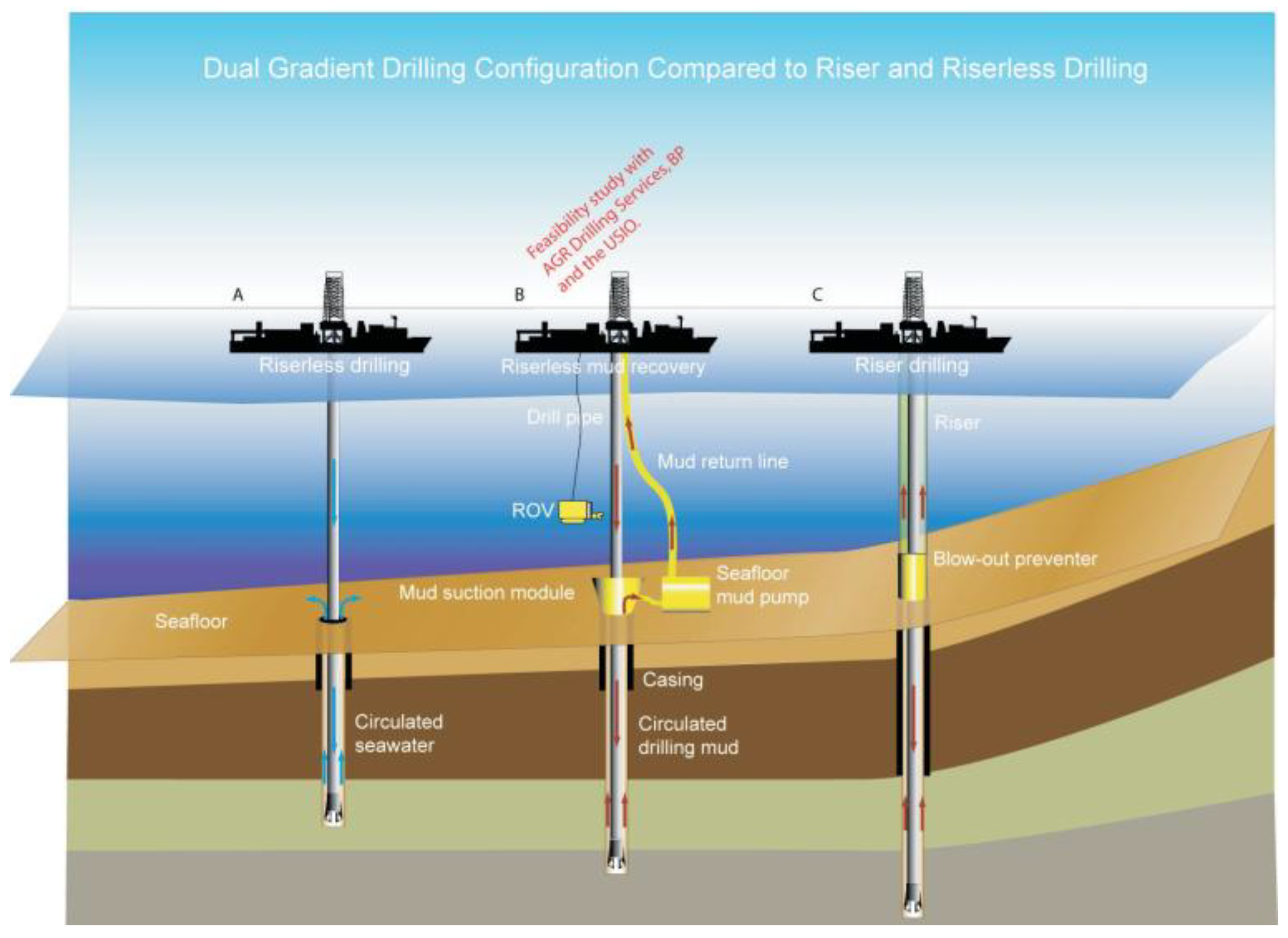
Figure 2.
Pressure Profiles of DGD and Conventional Drilling [18]. DGD (left): Low-density seawater (or an aerated fluid) was used from the sea surface to the seabed. This created the first, gentler pressure gradient. From the seabed to the bottom of the well, drilling mud of the required density was employed. This established a second, steeper gradient. This arrangement was equivalent to moving the drilling operation's "pressure reference point" from the sea surface to the seabed. Conventional Drilling (right): Drilling fluid extended from the sea surface downward. A continuous hydrostatic pressure gradient was formed through both the water column and the formation. In deepwater regions, this long, heavy column of mud generated very high static pressure at the seabed. Consequently, the narrow drilling window was often compressed or even "collapsed".
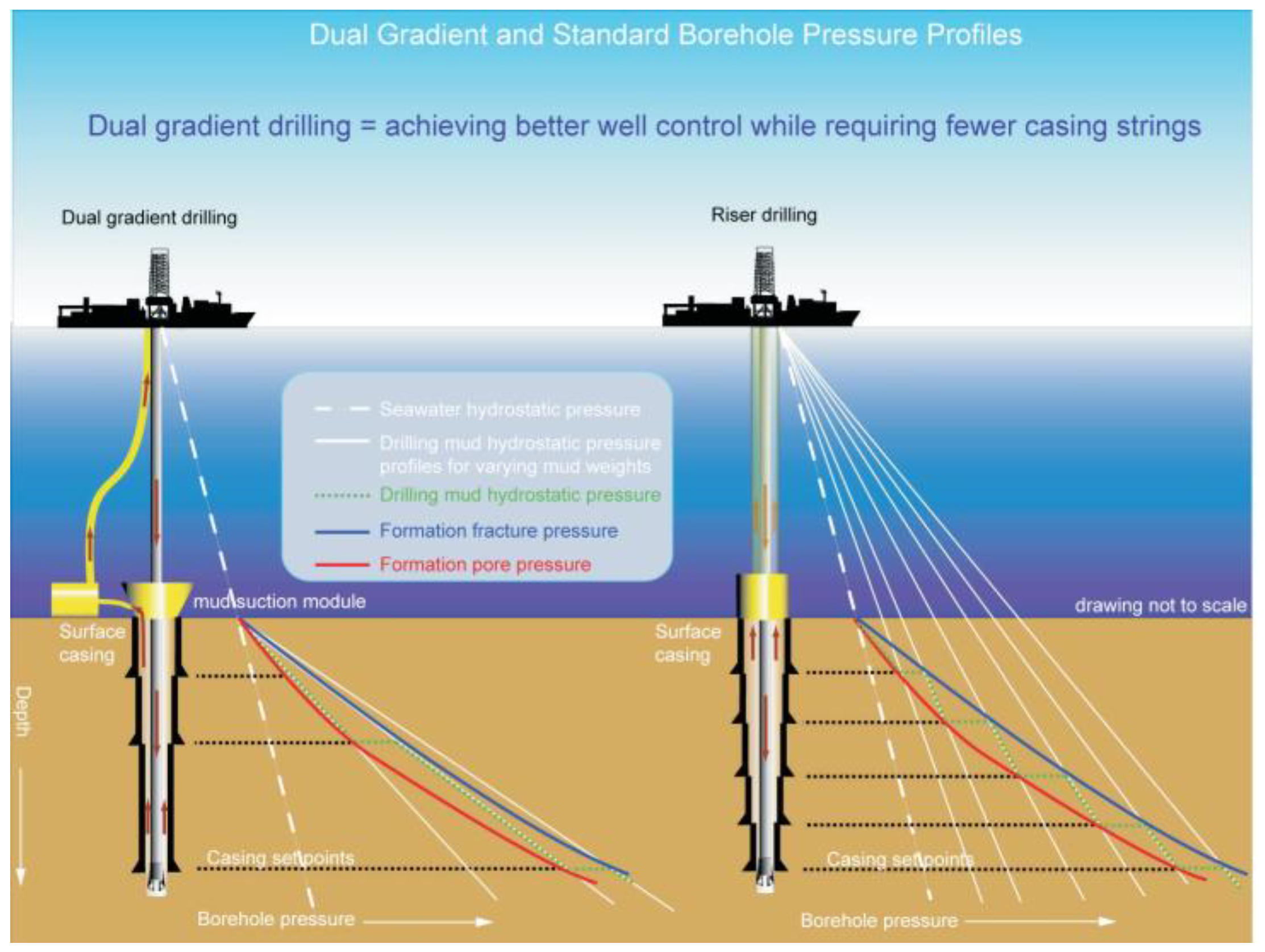
Figure 3.
The drillship "Pacific Santa Ana" [21].
Figure 3.
The drillship "Pacific Santa Ana" [21].
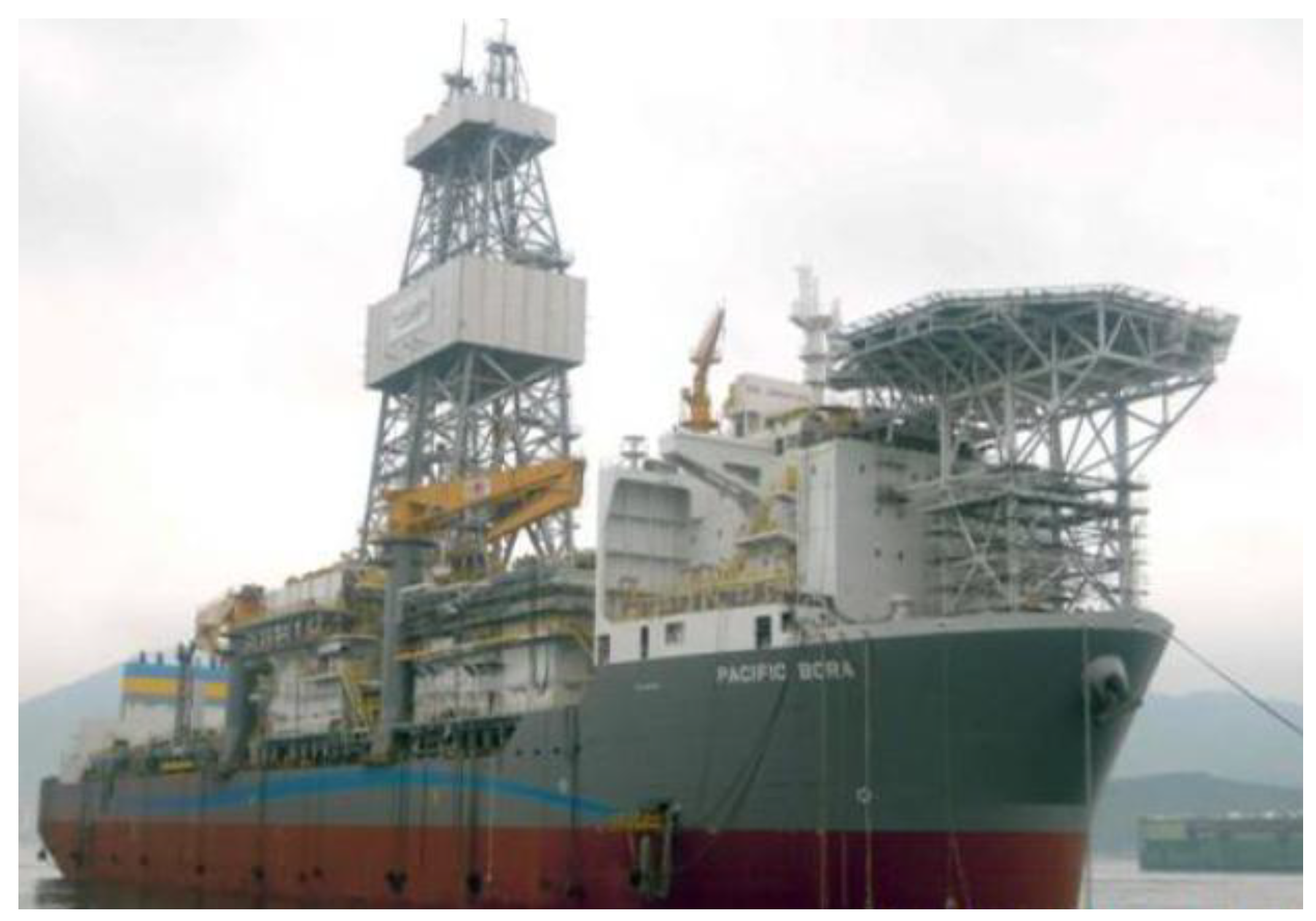
Figure 4.
Schematic of the LRRS [23].
Figure 4.
Schematic of the LRRS [23].
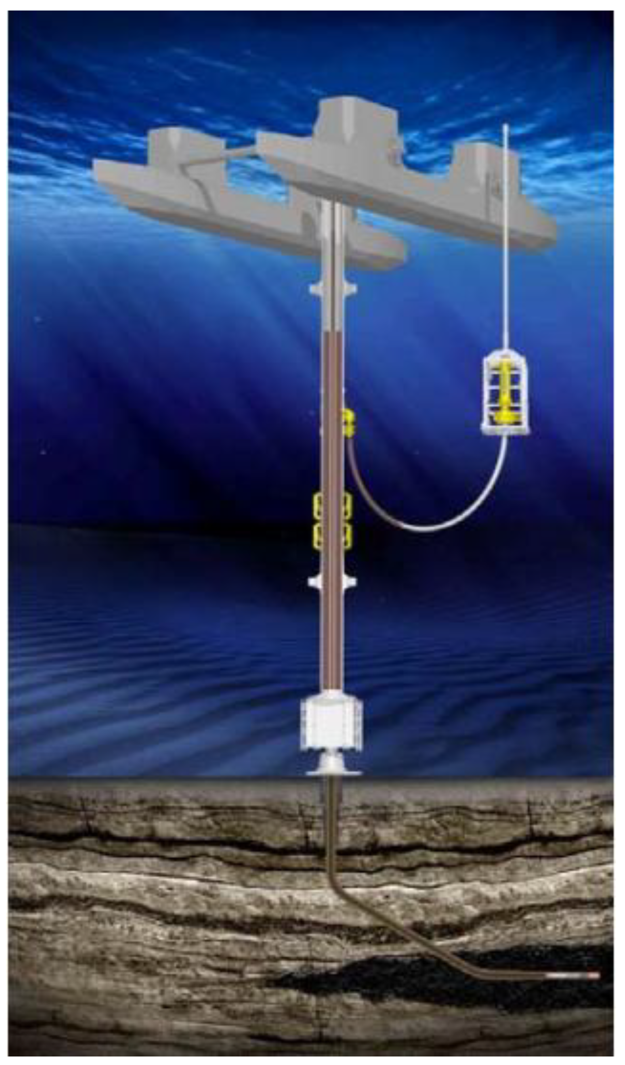
Figure 5.
Schematic diagram of the RMR system structure [26].
Figure 5.
Schematic diagram of the RMR system structure [26].
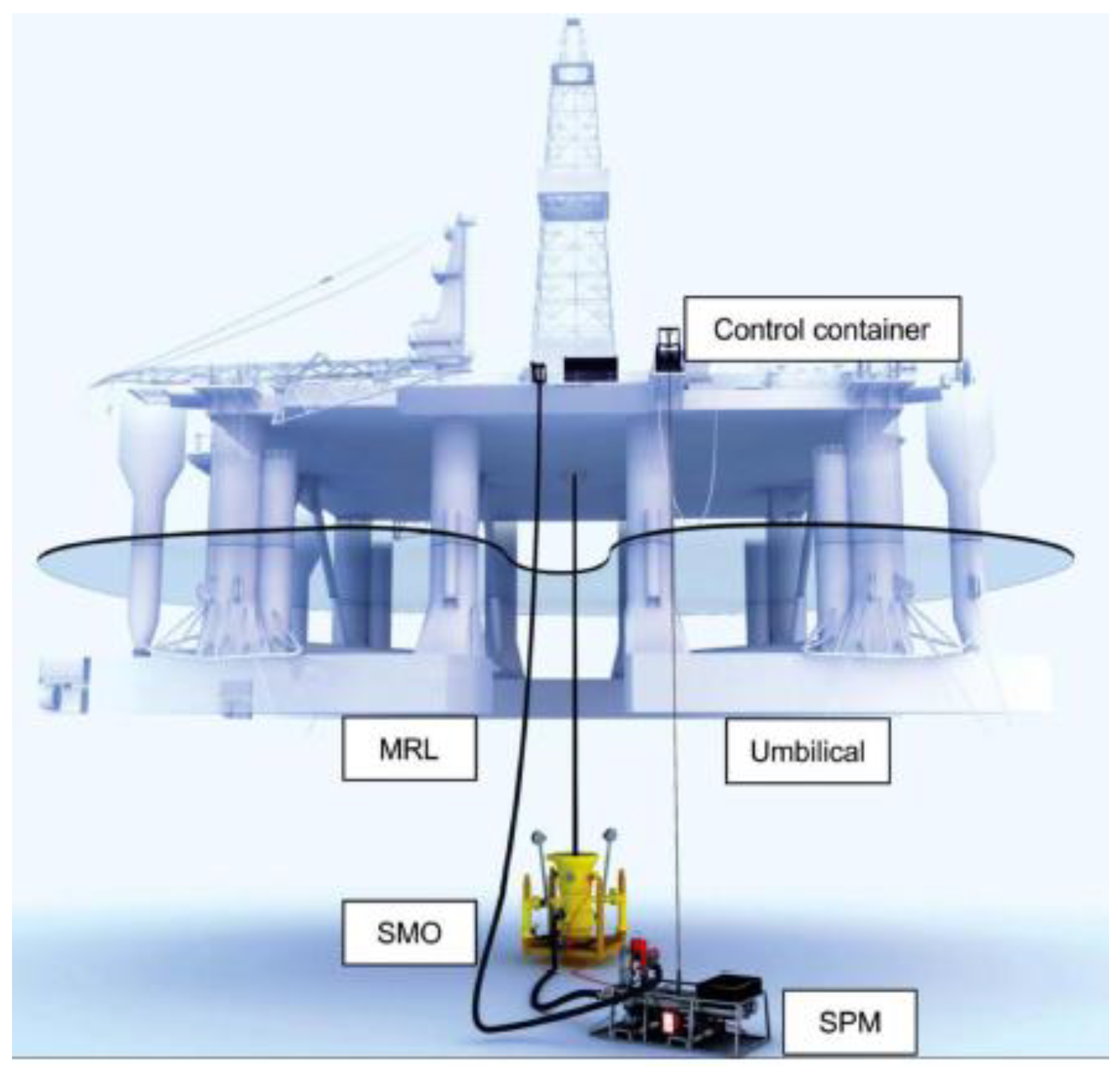
Figure 6.
Schematic of the SMO [27].
Figure 6.
Schematic of the SMO [27].
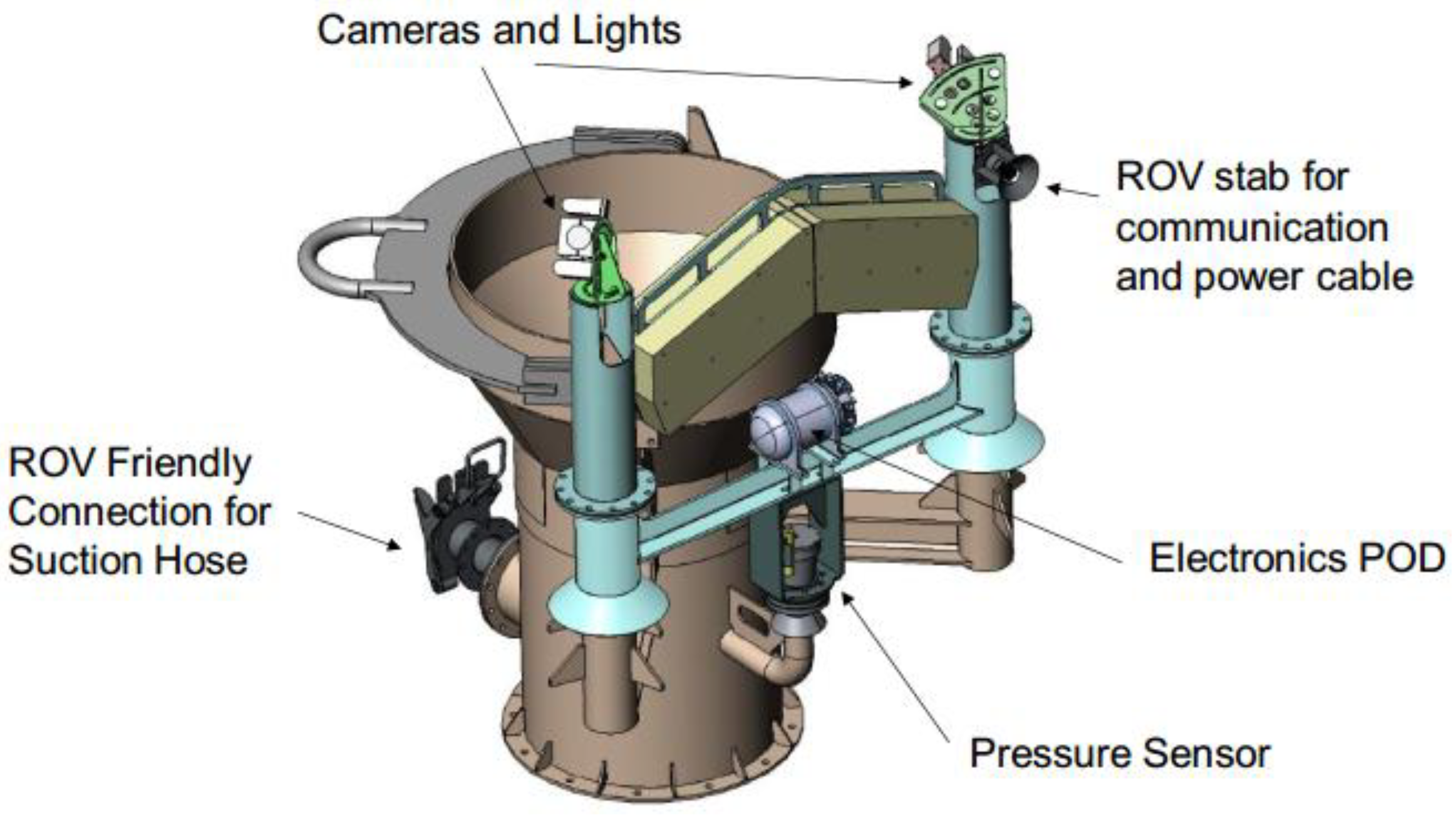
Figure 7.
SPM [31].
Figure 7.
SPM [31].
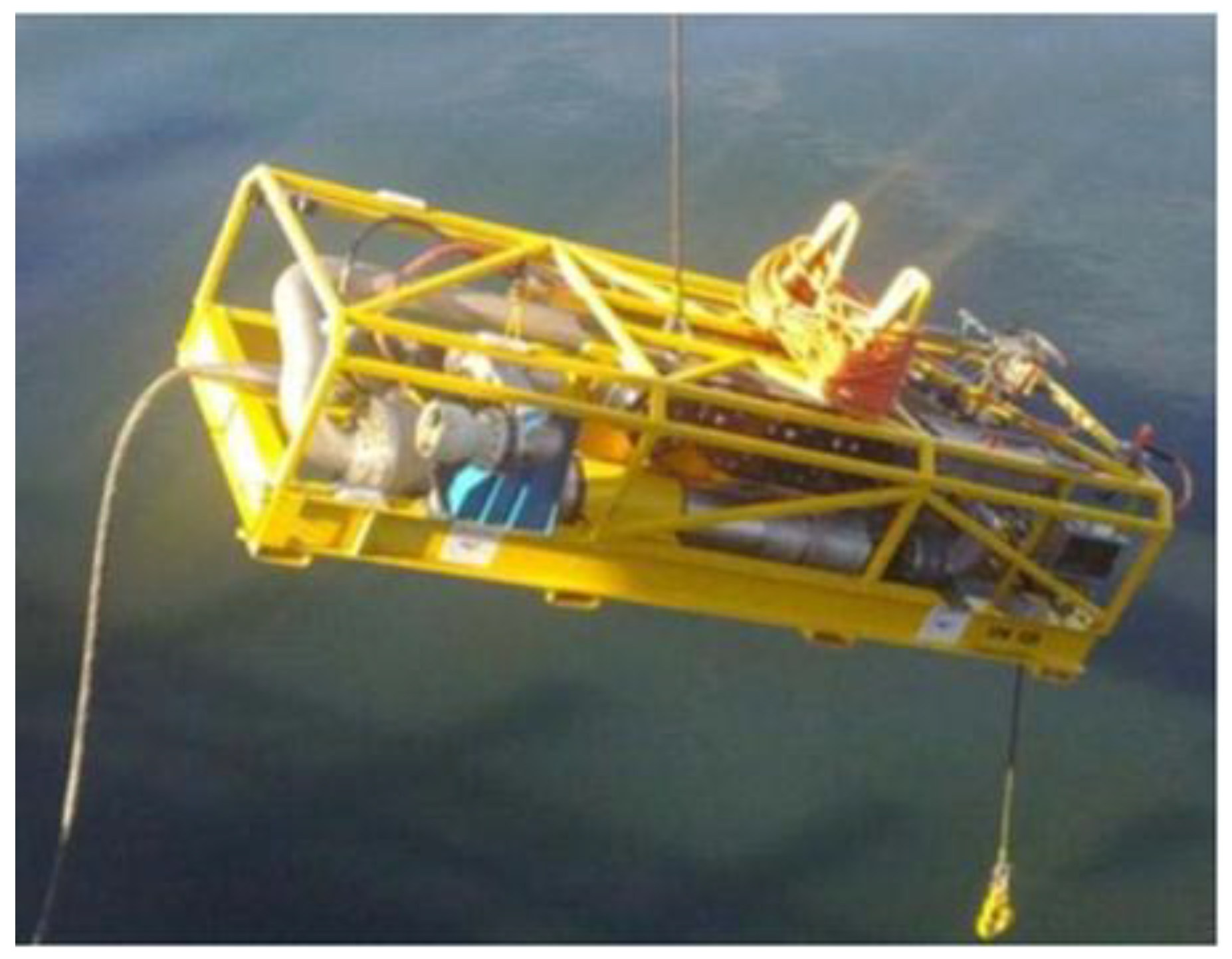
Figure 8.
MRL anchoring system [27].
Figure 8.
MRL anchoring system [27].
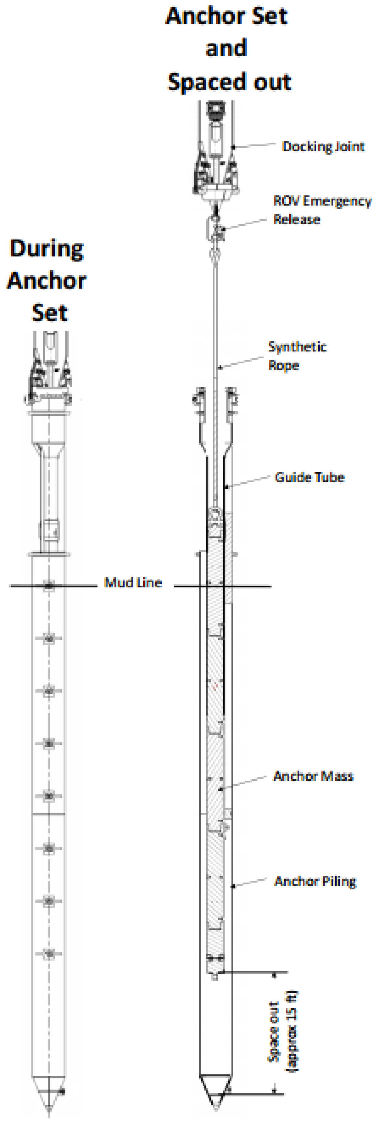
Figure 9.
RMR control system [27]: (a) RMR control container; (b) RMR monitoring system.
Figure 9.
RMR control system [27]: (a) RMR control container; (b) RMR monitoring system.
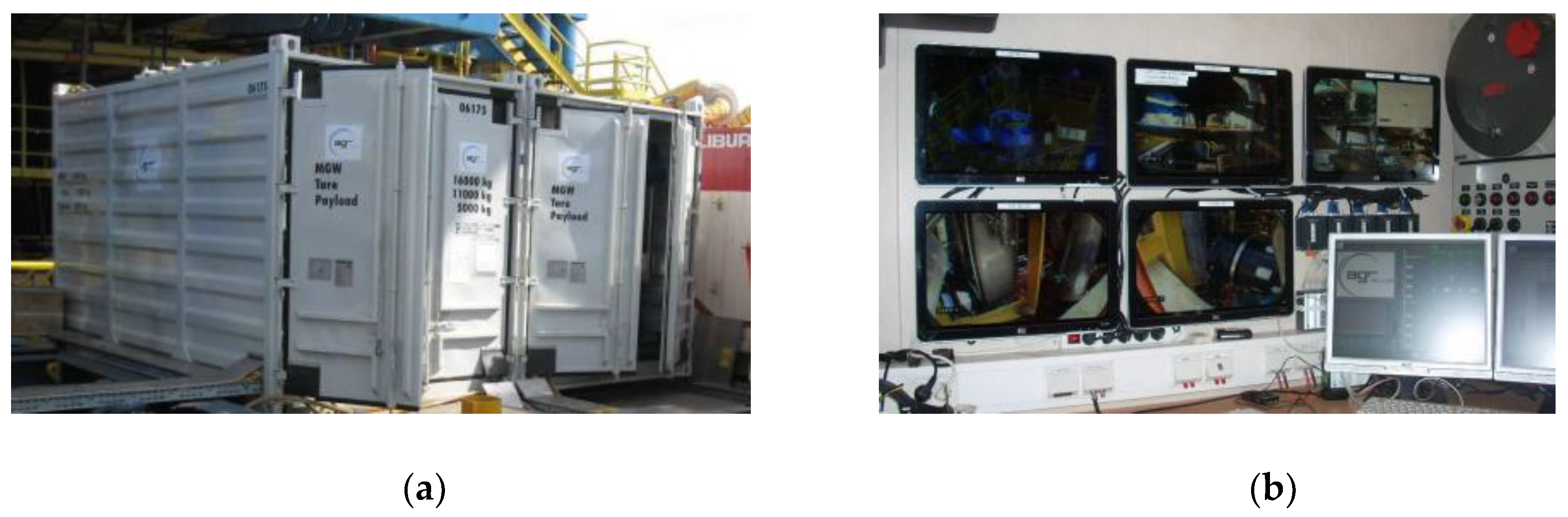
Figure 10.
Mud interface at the SMO while drilling [27].
Figure 10.
Mud interface at the SMO while drilling [27].
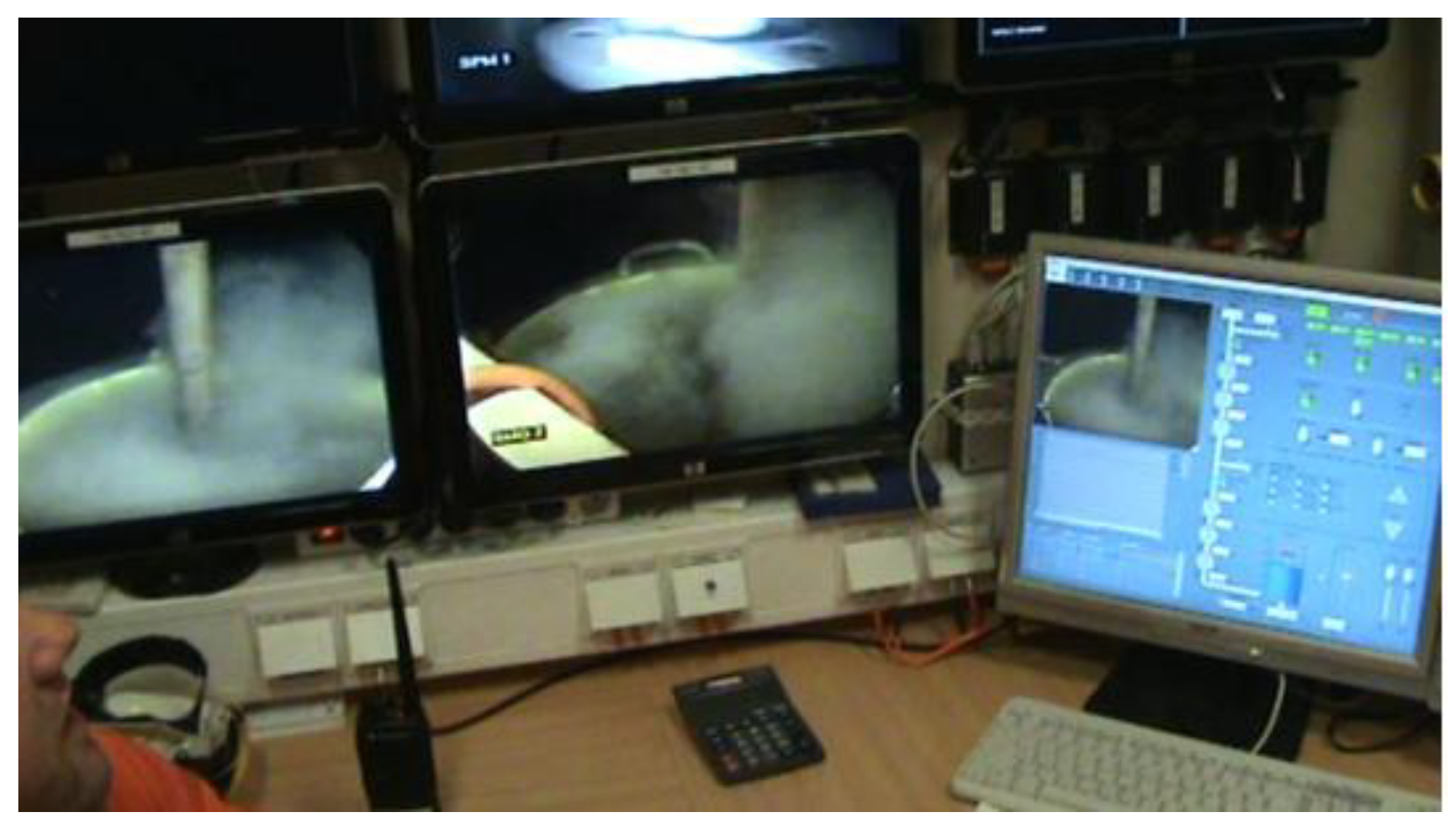
Figure 11.
Schematic of the CML apparatus [26].
Figure 11.
Schematic of the CML apparatus [26].
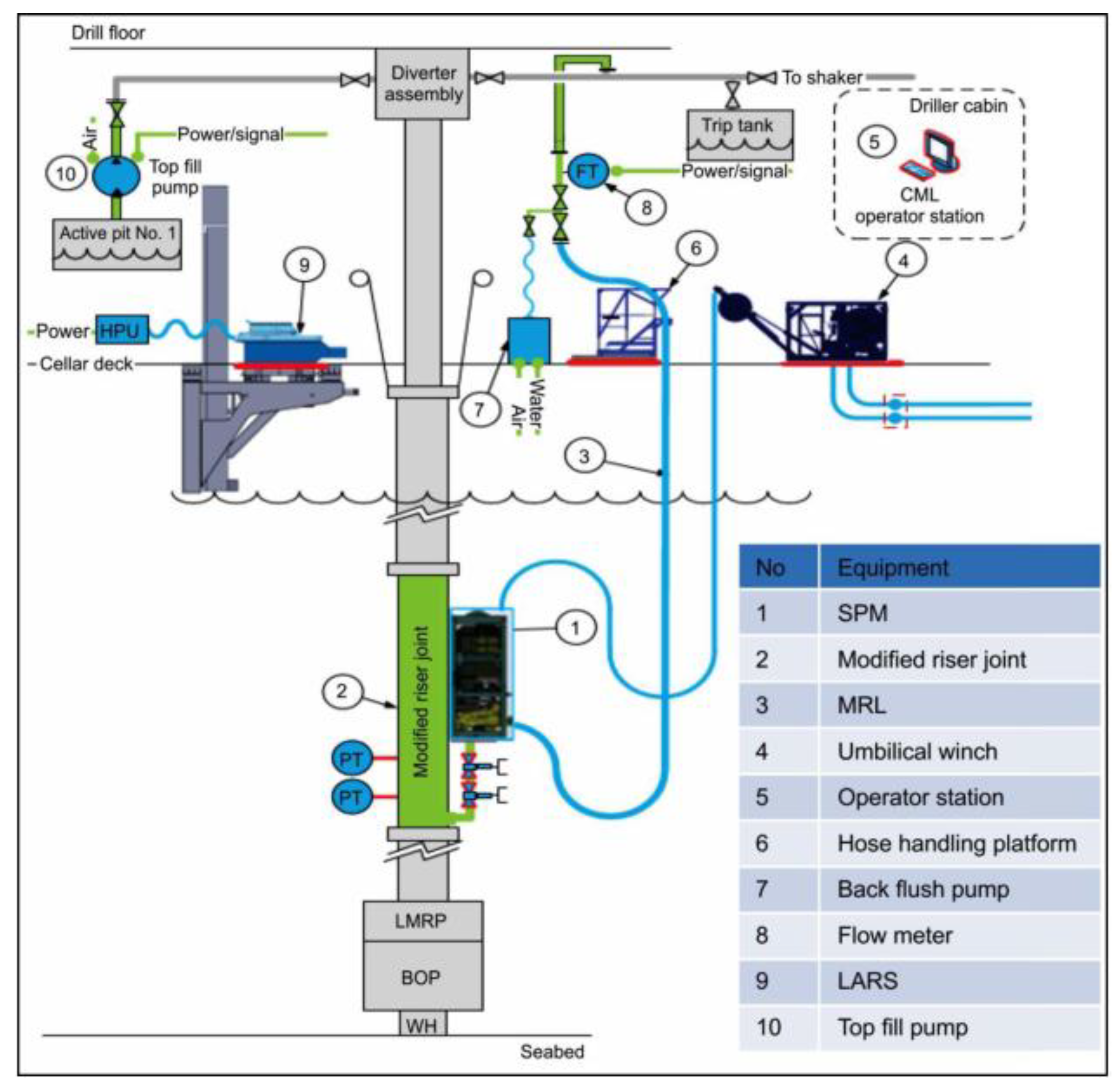

Table 1.
Global Application Statistics of RMR Technology and Corresponding Challenge Mitigation.
| Region/Basin | Representative Application Scale | Primary Geological/Engineering Challenges Addressed | Key Benefits and References |
|---|---|---|---|
| Caspian Sea | Early commercial application (15 wells), cumulative >52 wells | Validating technical feasibility, operations in environmentally sensitive areas | Achieving drilling fluid recovery, reducing cost and environmental impact [28,33] |
| North Sea | Widespread application, 73 reported wells | Shallow gas, narrow drilling margin, improving drilling efficiency | Enhancing early-stage well control safety, optimizing well architecture [41] |
| Australia | Browse Basin & Dampier Sub-basin, 29 reported wells | Shallow water flows in unconsolidated sands, severe vibrations in "Bare Sands" formation | Enabling stable drilling, setting a world record in combination with DWC [39,42] |
| Russian Far East | Sakhalin Island & Barents Sea, 7 reported wells | Operations in harsh environments, zero cuttings discharge requirement, weak formation pressure management | Complying with environmental regulations, achieving efficient pressure control [26,29] |
| Gulf of Mexico | Applications in multiple blocks, including deepwater | Complex shallow geohazards (shallow water flows, shallow gas, reactive clays) | Successful setting of deep surface casing, enabling minute-level early kick detection [43,44] |
| Brazil | Santos Basin, etc. | Wellbore stability challenges in extended-reach wells, formation erosion | Effective pressure window management using dual-gradient technology [45] |
| West Africa / Gulf of Guinea | Deepwater development projects | Deepwater narrow drilling margin, shallow flow risks | Providing a reliable dual-gradient drilling solution |
| Southeast Asia | Offshore Sabah, Malaysia (e.g., Malikai field) | Safe deepwater surface casing installation and high-quality cementing | Improving cementing conditions, ensuring wellhead stability [46] |
| Norwegian Sea | Multiple well applications, including the Zumba well | Extreme environmental requirements (coral protection), shallow water flows | Achieving "zero cuttings discharge" for the entire section, protecting the ecosystem [40,47] |
Disclaimer/Publisher’s Note: The statements, opinions and data contained in all publications are solely those of the individual author(s) and contributor(s) and not of MDPI and/or the editor(s). MDPI and/or the editor(s) disclaim responsibility for any injury to people or property resulting from any ideas, methods, instructions or products referred to in the content. |
© 2026 by the authors. Licensee MDPI, Basel, Switzerland. This article is an open access article distributed under the terms and conditions of the Creative Commons Attribution (CC BY) license (http://creativecommons.org/licenses/by/4.0/).
Copyright: This open access article is published under a Creative Commons CC BY 4.0 license, which permit the free download, distribution, and reuse, provided that the author and preprint are cited in any reuse.


