
Submitted:
21 January 2026
Posted:
22 January 2026
You are already at the latest version
Abstract
Traveling wave ultrasonic motors (TWUMs) are critical components in precision systems, their performance is susceptible to degradation under dynamic disturbances in harsh operating environments. This paper presents a monolithic U-shaped rotor designed to intrinsically achieve quasi-zero stiffness (QZS). Unlike conventional QZS systems that rely on assembling discrete positive and negative stiffness elements, the proposed design generates the target mechanical characteristic through the tailored nonlinear response of a unified U-shaped structure, thereby improving preload stability. Through exploring the critical parameters of the rotor cross-section, the finite element method (FEM) is employed to optimize the geometry configuration and characterize the mechanical performances. Simulation results show that the QZS behavior, demonstrating a stable force plateau of 320 ± 10 N across a 0.7 mm displacement range. A maximum von Mises stress of 788 MPa is obtained, well within the material's safety margin, thereby ensuring the structural integrity. Experimental tests validate the effectiveness of the proposed design. This compact, monolithic U-shaped rotor provides a robust and reliable QZS solution, demonstrating significant potential for enhancing the stability of TWUMs in applications prone to harsh environments such as extreme high and low temperatures, thermal cycling conditions, shock environments.
Keywords:
piezoelectric ultrasonic motor
; quasi-zero stiffness (QZS)
; U-shaped rotor
; monolithic design
; nonlinear mechanics
; finite element method (FEM)
1. Introduction
Piezoelectric ultrasonic motors, particularly traveling wave ultrasonic motors (TWUMs), have established themselves as the indispensable actuation components in precision engineering applications due to their unique operating principle and exceptional performance characteristics [1,2,3,4]. To form an effective friction pair between the stator and rotor, pressure must be applied normal to the contact surface, and pre-pressure plays a critical role in the performance of the motor and is one of the fundamental characteristics of ultrasonic motors [5,6].
The preload mechanism of ultrasonic motors, typically consisting of components such as springs, nuts, or shims, is set to a fixed value during assembly [7,8]. However, in harsh environments such as extreme high and low temperatures, thermal cycling conditions, shock environments, as well as prolonged cryogenic dormancy scenarios like those in Jupiter exploration, presenting a challenge for conventional TWUMs in avoiding the preload failure problem and ensuring the stability of the internal structure [9,10]. Quasi-zero-stiffness (QZS) systems offer a promising solution from vibration control theory. These systems maintain high static stiffness for load support while achieving low dynamic stiffness. This unique characteristic enables the effective isolation of ultralow-frequency vibrations and adaptability to load and environmental variations, a capability beyond the reach of linear isolation systems [11]. Therefore, developing ultrasonic motor structures with zero-stiffness characteristics to stabilize preload under harsh environments and varying operating conditions, thereby enhancing preload stability and robustness, represents a valuable research direction.
Currently, in order to achieve the high-quality mechanical shocks and vibration control of the precision system under the harsh conditions, drawing on the QZS characteristics for the vibration isolator design has become a crucial approach [12,13,14]. As far as we know, QZS belongs to a nonlinear stiffness characteristic commonly used in the vibration isolation, and the wide range of the static stiffness can guarantee the load-bearing capacity of the isolation system [15]. The mechanism of the QZS system is to construct the negative stiffness characteristic, and parallel it with the conventional positive stiffness mechanism. Through adjusting the parameters reasonably, the positive and negative stiffness at the static equilibrium point cancel each other out to achieve the QZS. Previously, a quantity of researchers had carried out the vibration isolator design on the QZS characteristics, such as the conventional mechanical springs [16,17,18,19], cam-roller-spring mechanisms [20,21,22], magnetic mechanisms [15,23,24], and bistable buckling beam mechanisms [25,26,27].
In general, constructing the mechanical springs with the negative stiffness mechanisms is a common type. A classic design of the vibration isolator with the three pairs of diagonal springs was proposed to achieve a wider QZS region with low transmittance [16]. The QZS behavior of the mechanical springs was studied to generate the wider isolation frequency band respect to the conventional isolators [17]. Moreover, Liu presented a X-shaped QZS isolator to improve the ultra-low frequency vibrations through the connections of the pivoted bars and springs [18]. An established and demonstrated the dynamics vibration isolator model with the QZS, which obtains the response of system under the quasi-periodic excitation [19]. The configuration and excitation parameters were analyzed to explore the bifurcation phenomenon and chaotic motion. For the cam-roller-spring mechanisms, Zhang demonstrated a vibration isolation system to consider the effect of the target vibration isolation performances [20]. Yao designed a high-static-low-dynamic stiffness isolator based on the specific cam-roller-spring mechanism, which acquires the dynamic response under the base excitation [21]. Regarding as the magnetic mechanisms with nonlinear forces, Wu constructed a combined structure with parallel the attractive and repulsive magnets that expands the displacement region of the QZS [22]. Wang exhibited a torsion dynamic vibration absorber system to achieve the synchronous vibration suppression and energy harvesting by the negative stiffness magnetic coupler in parallel with a pair of torsion coil springs [23]. To the bistable buckling beam mechanisms, a reusable bidirectional metamaterial with the QZS was proposed to investigate the region span and amplitude on the dynamic performances of the buffer energy absorbers [24]. Guo provided a multi-step QZS structure to achieve the multi-vibration mitigation and mechanical protection applications, where the elastic ring connected in parallel with two cross-curved beams for the various deformation behaviors [25]. In order to attenuate the acceleration under the multi-directional loads, a 3D negative stiffness metamaterial was exhibited to show the effect of the bidirectional negative stiffness and the desired buffering capacity [26]. Wang proposed a QZS disk rotor inspired by the design concept of slotted disk springs. This ultrasonic motor rotor achieves a QZS profile with a working range of 0.6 mm near the normal operational preload. Experimental validation demonstrates that the ultrasonic motor equipped with this disk spring rotor can largely maintain constant preload under certain impact-induced displacements and exhibit favorable output characteristics [27].
It is found that all of the above-mentioned QZS designs provide the static support with the positive stiffness for the vibration isolators, while the negative stiffness is employed to counteract the effect of the positive stiffness to achieve the QZS characteristics, which maintains the force of the high static support meanwhile achieving the lower dynamic stiffness. However, the non-monolithic QZS structure generated by the mutual cancellation of positive and negative stiffness segments inevitably expands its own volume, without meeting the requirements of the precision systems such as the TWUMs for the miniaturization, integration, and manufacturing consistency.
Thus, a separate monolithic structure with the QZS characteristic needs to be designed to generate the nonlinear mechanical response of the TWUM rotor customarily. Published research on this monolithic ultrasonic motor rotor design is currently very limited. Zhang studied the installation of a coil spring with the rotating groove as the buffering element in the original rotor of the TWUMs, and only locally slotted on the I-beam cross-section of the rotors [28]. For the reason of achieving the monolithic rotor design with the QZS characteristic and obtaining the nonlinear mechanical response for the shock and vibration control, this paper presents a monolithic U-shaped cross-section rotor design for the piezoelectric ultrasonic motors.
The remainder of this paper is organized as follows: Section II elaborates on the operating principle of the TWUM and the QZS evaluation mechanism for the rotor. The geometrical description of the monolithic U-shaped cross-section is introduced for parameterized modeling. Section III employs FEM simulations to analyze the mechanical properties and studies the influence of critical control parameters on QZS performance. Section IV presents experimental validation, comparing the results with simulations. The conclusion of this manuscript is summarized in Section V.
2. Operating Principle and Rotor QZS Evaluation Mechanism
2.1. Operating Principle and Conditions
Unlike the traditional motors that rely on the electromagnetic force transmission, the ultrasonic motors generate the controllable micro vibrations by exciting the stator with the piezoelectric ceramics, and convert them into macro rotation of the rotor through the friction between the stator and rotor. The schematic diagram of the TWUM operating principle is shown in Figure 1. Based on this operating principle, the 3D mechanical explosion diagram of the main components in the TWUMs is illustrated in Figure 2a. Figure 2b depicts the standard initial rotor with a diameter of 70 mm, which serves as the base for the monolithic rotating body cross-section design without altering the external frame dimensions. The stator is aligned within the same dimensional range.
A stable preload is applied to the contact surface between the stator and rotor through the elastic deformation of the rotor, ensuring smooth motor operation and output performance. The preload on the rotor for the TWUM is set to 320 ± 10 N. The stator is fixed and connected to the rotor via a contact surface. The rotor and stator materials are titanium and copper alloys, respectively. Their densities are 4510 kg/m³ and 8780 kg/m³, elastic moduli are 110 GPa and 113 GPa, and Poisson's ratios are 0.34 and 0.33. The maximum allowable stress for the rotor is 800 MPa.
2.2. The Evaluation Mechanism of the Rotor QZS
This section defines the evaluation mechanism for the rotor QZS, which generates a constant force within a specific displacement interval. The monolithic cross-section structure of the rotor, when subjected to an unstable critical load, bends laterally, forming approximate Euler beams with unique nonlinear mechanical properties [29,30,31]. This feature is utilized to determine the QZS characteristic by constructing the force-displacement relationship based on the complementary strain energy principle [32]. Figure 3 shows the schematic of this relationship for the rotor cross-section. Herein, the zero-stiffness characteristic is evaluated using:
where and are the reaction force and displacement at the i-th point within the designated intervals (). Within the QZS range, the stiffness approaches a small value, and the force tends to remain constant. The QZS calculation is expressed as:
where represents the average stiffness at discrete segments, and n is the number of the discrete segments. The displacement range corresponding to is taken as the target QZS interval. Based on the TWUM operating principle and this QZS evaluation mechanism, the proposed U-shaped cross-section is described next.
2.3. Description of the Monolithic U-Shaped Cross-Section Rotor Configuration
To establish a parameterized model of the rotor system with QZS, a monolithic U-shaped cross-section is introduced to enhance preload stability. Figure 4 illustrates the cross-sections of the initial rotor and the proposed U-shaped rotor, with the parameters of the U-shaped cross-section detailed in Section 3.2. The U-shaped cross-section is chamfered at sharp corners to avoid stress concentration. The inverted C-shaped contact end is symmetrically designed to adapt to the milling cutter, featuring the same chamfer radius on both inner and outer right edges. On the left side, an internal chamfer structure is adopted at the bend end, and a rectangular groove is implemented to satisfy machining and installation requirements.
Subsequently, numerical analysis and parametric design are employed to investigate the influence of critical structural parameters beyond manufacturing dimensions, elucidating the design evolution process of the monolithic U-shaped rotor cross-section.
3. Numerical Analysis and Parametric Design
3.1. The FEM Analysis
In order to compute the performances details of the parameterized modeling, the FEM simulation analysis is utilized to express the nonlinear mechanical response of the U-shaped rotor cross-section by the Abaqus software. The specific FEM simulation process is given as follows:
As the rotors for both TWUM types are constant cross-section rotating bodies, a second-order hexahedral element was used for meshing to balance computational accuracy and complexity. The mesh generation for the initial and proposed U-shaped rotor cross-sections is shown in Figure 5.
Based on the operation principle of the TWUM, the stator is bonded to the piezoelectric ceramic through the glue layer for suppressing the relative motion, and the same statement is applied between the stator and the base. The lower surface of the rotor contacts the upper surface of the stator to generate the frictional motion, and the friction coefficient is set to 0.2. Consequently, the preload is applied along the central axis of the rotor. The loading and boundary condition constraints are shown in Figure 6.
To avoid the influence of grid number on the simulation results, a mesh independence verification for U-shaped cross-section rotor was conducted, as summarized in Table 1. The maximum stress at a displacement of 1.9 mm was used as the mechanical response indicator. The change in maximum stress in Mesh II was 2.2% compared to Mesh I. Compared to Mesh I and II, the maximum stress in Mesh III changed by 2.4% and 0.26%, respectively. The maximum stress in Mesh IV showed only a slight adjustment of 0.14% compared to Mesh III. Considering computational accuracy and cost, Mesh III was selected for numerical analysis.
The relationship between preload and rotor deformation was established to improve the QZS characteristics. To comprehensively analyze the simulation results, the maximum stress comparisons for the initial rotor and the proposed U-shaped rotor cross-section are shown in Figure 7 and Figure 8, respectively. Initial cross-section of the rotor rotating body is shown in Figure 4a. The simulation results of the initial cross-section and the rotor are displayed, and the Von-Mises stress contour plots are shown in Figure 7a and Figure 7b, respectively. The maximum stress of the initial rotor structure is 811 MPa (exceeding the 800 MPa allowable limit) since the displacement is 1.30 mm, and the stress concentration region is located at the left root. The U-shaped cross-section rotating body of the rotor is proposed in Figure 4b. The Von-Mises stress contour plots of the rotor with the proposed maximum stress are illustrated in Figure 8a and Figure 8b, respectively. The maximum stress of the proposed U-shaped cross-section is only 523 MPa when the displacement is 1.3 mm. It is completely within the safety margin of the material, which demonstrates the integrity of the rotor structure. It is found that comparing to the initial cross-section, the proposed U-shaped cross-section shows a significant reduction in the stress concentration.
3.2. Design of the Critical Control Parameters
In this section, the critical control parameters of the proposed U-shaped rotor cross-section are designed to improve the QZS characteristics. Figure 9 illustrates the geometry configurations of the proposed U-shaped rotating body cross-section. The manufacturing process dimensions of , , , are set to 3.5 mm, 0.3 mm, 0.2 mm, and 0.3 mm. The length of contact surface is a constant value of 2.55 mm. In addition to the manufacturing process dimensions, the critical control parameters include the cross-section length , the block thickness , the radius of the cross-section , the cross-section width , and the vertical cross-section thickness . The critical control parameters of the U-shaped cross-section are utilized to study the influence on the QZS of the rotor structure based on the relationship between the preload and the rotor deformation.
Figure 10, Figure 11, Figure 12 demonstrate the variations by adjusting , , and at the contact end, respectively. It is seen that both the stiffness characteristic transitions from the negative stiffness to QZS, and then to the positive stiffness, where set to the parameterization range of 0.5 mm~1.6 mm, respectively. The influence of is almost similar to within the range of 0.6 mm~1.6 mm. As increases from 0.25 mm to 0.32 mm, the range of the QZS interval continuously decreases and tends toward the positive stiffness characteristics. In Figure 13, is set to the range of 0.36 mm~1.36 mm, and the impact trend of is roughly the same as that of , . In Figure 14, is set to the range of 0.3mm~0.4 mm, which also exhibits the positive stiffness as the number value increases.
By tuning the critical control parameters, we obtained a combination that successfully delivers the QZS characteristics under the target preload of 320 ± 10 N. Hence, the U-shaped cross-section design of the rotor is formed, and the parameter configuration is shown in Table 2.
Figure 15 compares the QZS intervals of the two rotor designs by plotting displacement against reaction force. The preload of the initial cross-section rotor increases steadily with displacement, exhibiting positive stiffness without a QZS interval. In contrast, the proposed U-shaped cross-section rotor achieves a QZS interval within 1.2 mm~1.9 mm under a stable 320 ± 10 N preload. The maximum stress 788MPa remains below the material's allowable limit. Here, the average stiffness = 26.92 MPa. Compared to the initial design, the U-shaped rotor provides a wide QZS interval within the material's safety margin, meeting TWUM rotor design standards.
4. Experiment Evaluation
Experimental evaluation was conducted to validate the numerical analysis of the U-shaped cross-section rotor design. Figure 16a shows the typical specimens used for mechanical testing, and Figure 16b shows the schematic diagram of the testing environment. Three rotor samples and related fixtures were manufactured using a computer numerical control (CNC) machine tool. The testing machine gradually increased the load on the sample's high-stiffness part (central axis) to the target preload.
Figure 17 illustrates the experimental evaluation process for the typical specimens. Three specimens were tested sequentially to ensure repeatability and minimize random errors. To explicitly verify that the structure remained within its elastic range and no damage occurred, repeated tests (e.g., curves labeled 1-1 and 1-2 for Specimen #1) were conducted on the same specimen. The force-displacement data during compression were recorded via a data acquisition system. A comparison between the simulation and experimental results is given in Figure 18. It can be observed that the response of Specimen #3 agrees well with the simulation within the allowable error. However, for Specimens #1 and #2, the deviation from the simulated curve increases when the displacement exceeds 1.5 mm, showing a measured stiffness higher than predicted. This discrepancy is primarily attributed to machining tolerances in the thickness (h). Despite minor deviations in absolute values, the overall experimental trends confirm the design's effectiveness, successfully maintaining a preload of approximately 320 ± 10 N and achieving a target QZS range of nearly 0.7 mm.
5. Conclusions
This study proposed a monolithic U-shaped rotor with quasi-zero stiffness for piezoelectric ultrasonic motors, aimed at enhancing preload stability under dynamic disturbances. The design intrinsically achieves QZS through a unified structural configuration, eliminating the need for assembled positive-negative stiffness elements. Using finite element analysis, we optimized the geometric parameters of the rotor cross-section, achieving a stable force plateau of 320 ± 10N about a 0.7 mm displacement range, with a maximum von Mises stress of 788 MPa-well within the material’s safety limit. Experimental tests validated the simulation results. This study has primarily focused on the design and quasi-zero-stiffness characterization of the monolithic rotor. Building upon this foundation, Future work will involve rigorous experimental validation of its performance under harsh environmental conditions. The ultimate objective is to integrate and test this rotor within functional ultrasonic motor prototypes to definitively demonstrate its practical applicability and value in real-world products.
Author Contributions
Conceptualization, J.W. and H.L.; methodology, J.W.; software, J.W. and H.L.; validation, J.W. and H.L.; formal analysis, J.W.; investigation, J.W. and H.L.; resources, J.W.; data curation, J.W. and H.L.; writing—original draft preparation, J.W. and H.L.; writing—review and editing, J.W. and H.L.; visualization, J.W.; supervision, J.W.; project administration, J.W.; funding acquisition, J.W. and H.L. All authors have read and agreed to the published version of the manuscript.
Funding
This research was funded by the National Natural Science Foundation of China (Grant numbers: U22B2082, U2037603, and 52277055), These financial supports are gratefully acknowledged.
Data Availability Statement
Data are contained within the article.
Conflicts of Interest
The authors declare no conflicts of interest.
References
- Chen, Y.; Wei, Y.; Huang, Z.; Lu, X.; Liu, W. Rapid motion of Janus Mg-based micromotors in urine environment by ultrasonic actuation. Colloid Surfaces A 2025, 718, 136932. [Google Scholar] [CrossRef]
- Shi, M.; Gao, M; Chen, S.; Zhang, S.; Miao, X. Performance evaluation of a novel disk-type motor using ultrasonic levitation: Modeling and experimental validation. Precis. Eng. 2024, 91, 174–184. [Google Scholar] [CrossRef]
- Difeo, M.; Pérez, N.; Castro, M.; Madrigal, J.; Rubio-Marcos, F.; Ramajo, L.; Cavalieri, F. Performance evaluation of lead-free potassium sodium niobate-based piezoceramics for ultrasonic motor design. Ceram. Int. 2025, 51, 13646–13653. [Google Scholar] [CrossRef]
- Chen, B.; Yang, J.; Tang, H.; Wu, Y.; Zhang, H. Optimization of flexible rotor for ultrasonic motor based on response surface and genetic algorithm. Micromachines-Basel 2025, 16, 54. [Google Scholar] [CrossRef]
- Yin, H.; Wang, L.; Li, P.; Liu, J. Preload multi-objective optimization method for ultrasonic motors based on NSGA-II. Processes 2024, 12, 2899. [Google Scholar] [CrossRef]
- Wang, H.; Pan, Z.; Zhu, H.; Guo, Y. Pre-pressure influences on the traveling wave ultrasonic motor performance: A theoretical analysis with experimental verification. AIP Adv. 2020, 10, 115211. [Google Scholar] [CrossRef]
- Li, Z.; Zhao, H.; Che, S.; Chen, X.; Sun, H. Analysis of preload of three-stator ultrasonic motor[J]. Micromachines-Basel 2021, 13, 5. [Google Scholar] [CrossRef]
- Liu, J.; Niu, R.; Zhu, H.; Zhao, C. Improving the efficiency of a hollow ultrasonic motor by optimizing the stator’s effective electromechanical coupling coefffcient. Rev. Sci. Instrum. 2020, 91, 016104. [Google Scholar] [CrossRef]
- Shi, M.; Gao, M.; Chen, S.; Zhang, S.; Miao, X. Performance evaluation of a novel disk-type motor using ultrasonic levitation: Modeling and experimental validation. Precis. Eng. 2024, 91, 174–184. [Google Scholar] [CrossRef]
- Pan, Q.; Zhang, Y.; Chen, X.; Wang, Q.; Huang, Q. Development of a novel resonant piezoelectric motor using parallel moving gears mechanism. Mechatronics 2024, 97, 103097. [Google Scholar] [CrossRef]
- Dou, J.; Yao, H.; Cao, Y.; Wang, Z. Permanent magnet based nonlinear energy sink for torsional vibration suppression of rotor systems. Int. J. Nonlin. Mech. 2023, 149, 104321. [Google Scholar] [CrossRef]
- Meng, Q.; Hou, L.; Lin, R.; Chen, Y.; Saeed, N.; Fouly, A.; Awwad, E. On a quasi-zero stiffness vibration isolator with multiple zero stiffness points for mass load deviation. Appl. Math. Model. 2025, 145, 116112. [Google Scholar] [CrossRef]
- Hua, X.; Wang, S.; Zhang, J.; Jiao, G.; Wang, K. Miura-origami inspired quasi-zero stiffness low-frequency vibration isolator. Int. J. Mech. Sci. 2025, 295, 110283. [Google Scholar] [CrossRef]
- Dou, J.; Yao, H.; Li, H.; Li, J.; Jia, R. A track nonlinear energy sink with restricted motion for rotor systems. Int. J. Mech. Sci. 2023, 259, 108631. [Google Scholar] [CrossRef]
- Wang, J.; Yao, G.; Tao, Y. Nonlinear dynamics and vibration reduction properties of a quasi-zero stiffness magnetic isolator under translational and rotational coupling excitation. Mech. Syst. Signal Pr. 2025, 232, 112758. [Google Scholar] [CrossRef]
- Zhao, F.; Ji, J.; Ye, K.; Luo, Q. An innovative quasi-zero stiffness isolator with three pairs of oblique springs. Int. J. Mech. Sci. 2021, 192, 106093. [Google Scholar] [CrossRef]
- Gatti, G. A nonlinear quasi-zero stiffness vibration isolator with quintic restoring force characteristic: A fundamental analytical insight. J. Vib. Control 2023, 30, 4185–4198. [Google Scholar] [CrossRef]
- Liu, H.; Chai, Y.; Miao, Z.; Li, F. Enhanced design of X-shaped structure for ultra-low-frequency nonlinear vibration isolation. Int. J. Struct. Stab. Dy. 2025. [Google Scholar] [CrossRef]
- An, J.; Tan, X.; Wu, J.; He, H. The influence of quasi-zero stiffness system parameters on response stability under quasi-periodic excitation. Nonlinear Dynam 2025, 113, 19241–19257. [Google Scholar] [CrossRef]
- Zhang, Y.; Wei, G.; Wen, H.; Jin, D.; Hu, H. Design and analysis of a vibration isolation system with cam-roller-spring-rod mechanism. J. Vib. Control 2022, 28, 1781–1791. [Google Scholar] [CrossRef]
- Yao, Y.; Li, H.; Li, Y.; Wang, X. Analytical and experimental investigation of a high-static-low-dynamic stiffness isolator with cam-roller-spring mechanism. Int. J. Mech. Sci. 2020, 186, 105888. [Google Scholar] [CrossRef]
- Wu, J.; Che, J.; Chen, X.; Jiang, W. Design of a combined magnetic negative stiffness mechanism with high linearity in a wide working region. Sci. China Technol. Sc. 2022, 65, 2127–2142. [Google Scholar] [CrossRef]
- Wang, Q.; Zhou, J.; Wang, K.; Pan, H.; Gao, J.; Lin, Q.; Tan, D. A torsion quasi-zero stiffness harvester-absorber system. Acta Mech. Sinica-Prc. 2025, 41, 524252. [Google Scholar] [CrossRef]
- Guo, S.; Liu, S.; Gao, R. A bidirectional quasi-zero stiffness metamaterial for impact attenuation. Int. J. Mech. Sci. 2024, 268, 108998. [Google Scholar] [CrossRef]
- Guo, S.; Gao, R.; Tian, X.; Liu, S. A quasi-zero-stiffness elastic metamaterial for energy absorption and shock attenuation. Eng. Struct. 2023, 280, 115687. [Google Scholar] [CrossRef]
- Guo, S.; Gao, R.; Tian, X.; Liu, S. A 3D metamaterial with negative stiffness for six-directional energy absorption and cushioning. Thin Wall. Struct. 2022, 180, 109963. [Google Scholar] [CrossRef]
- Wang, X.; Jian, L.; Chen, C.; Wang, J. Design and optimization of Quasi-zero-stiffness rotor for disc ultrasonic motor. Piezoelectrics & Acoustooptics 2019, 41. [Google Scholar]
- Zhang, J.; Yang, L.; Chen, H.; Ma, S.; Shen, X.; Chen, L. Design of travelling-wave rotating ultrasonic motor under high overload environments: Impact dynamics simulation and experimental validation. Appl. Sci. 2019, 9, 5309. [Google Scholar] [CrossRef]
- Qiu, J.; Lang, J.; Slocum, A. A curved-beam bistable mechanism. J. Microelectromech. S. 2004, 13, 137–146. [Google Scholar] [CrossRef]
- Gao, R.; Guo, S.; Tian, X.; Liu, S. A negative-stiffness based 1D metamaterial for bidirectional buffering and energy absorption with state recoverable characteristic. Thin Wall. Struct. 2021, 169, 108319. [Google Scholar] [CrossRef]
- Aung, Z.; Vo, D.; Suttakua, P.; Atroshchenko, E.; Bui, T.; Rungamornrat, J. Peridynamic formulations for planar arbitrarily curved beams with Euler-Bernoulli beam model. Thin Wall. Struct. 2024, 204. 112278. [Google Scholar] [CrossRef]
- Lu, Y.; Luo, Q.; Tong, L. Topology optimization for metastructures with quasi-zero stiffness and snap-through features. Compu. Method Appl. M. 2025, 434, 117587. [Google Scholar] [CrossRef]
Figure 1.
Schematic diagram of the TWUM operating principle.
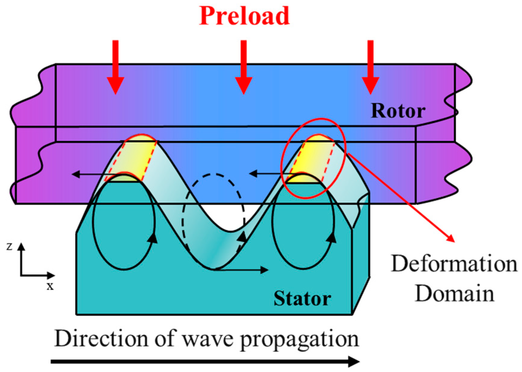
Figure 2.
3D reconstruction of the ultrasonic motor: (a) Mechanical explosion diagram; (b) Initial rotor and stator.
Figure 2.
3D reconstruction of the ultrasonic motor: (a) Mechanical explosion diagram; (b) Initial rotor and stator.

Figure 3.
Schematic diagram of the force-displacement relationship of the rotor rotating body cross-section: (a) Schematic of the rotor cross-section; (b) Force-displacement curve.
Figure 3.
Schematic diagram of the force-displacement relationship of the rotor rotating body cross-section: (a) Schematic of the rotor cross-section; (b) Force-displacement curve.
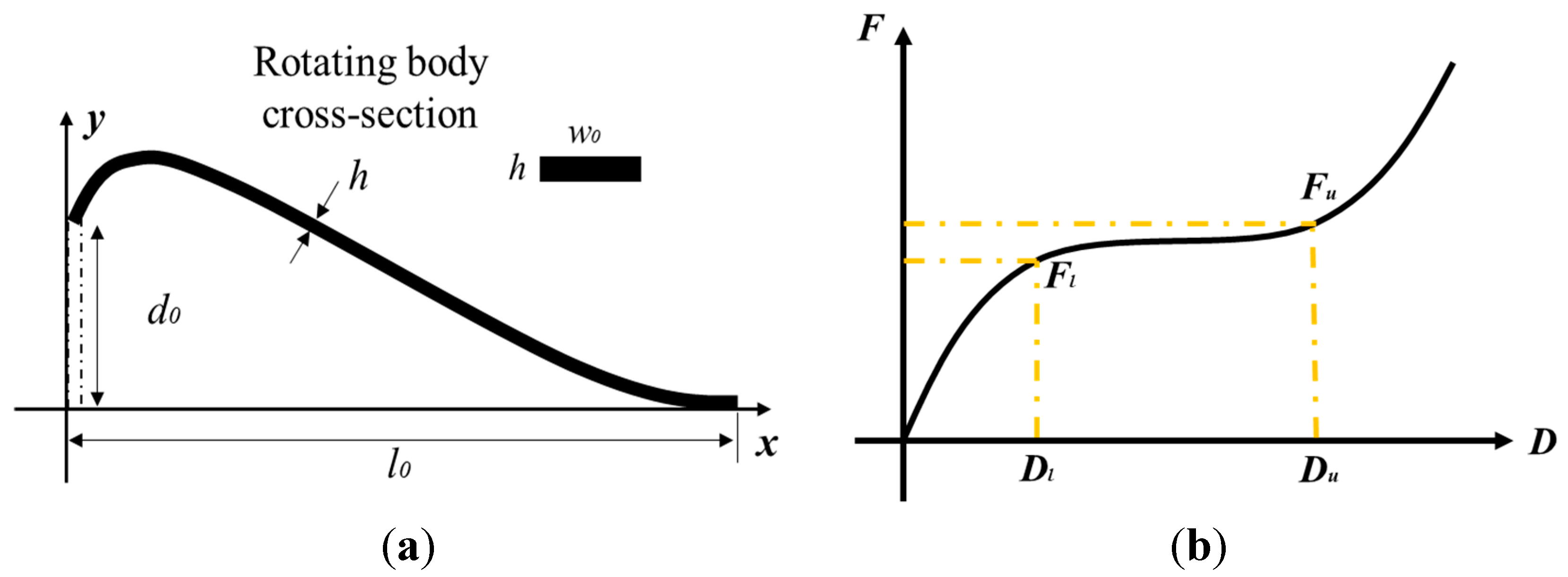
Figure 4.
Cross-sections of the initial rotor and the U-shaped rotor rotating bodies.
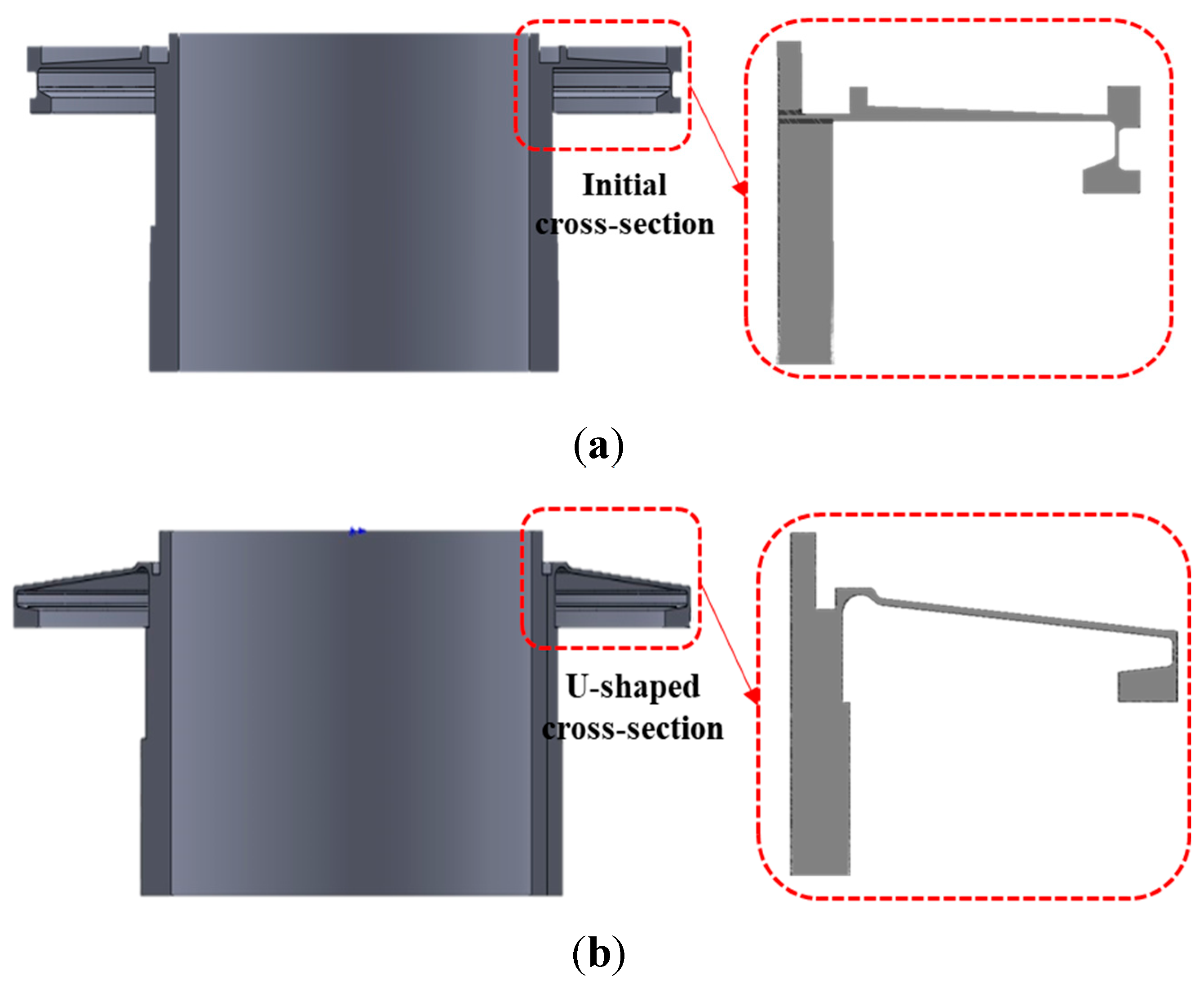
Figure 5.
Mesh generation of the (a) initial rotor and (b) proposed U-shaped cross-section.
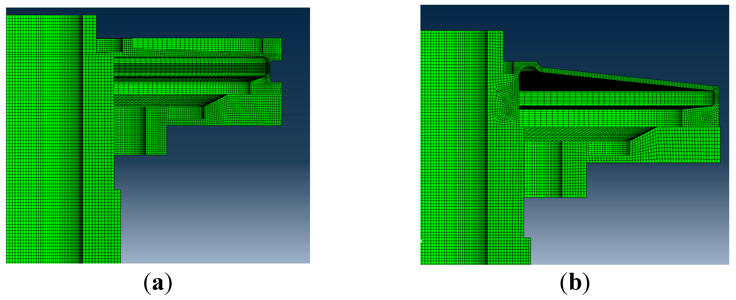
Figure 6.
Loading and boundary condition constraints.
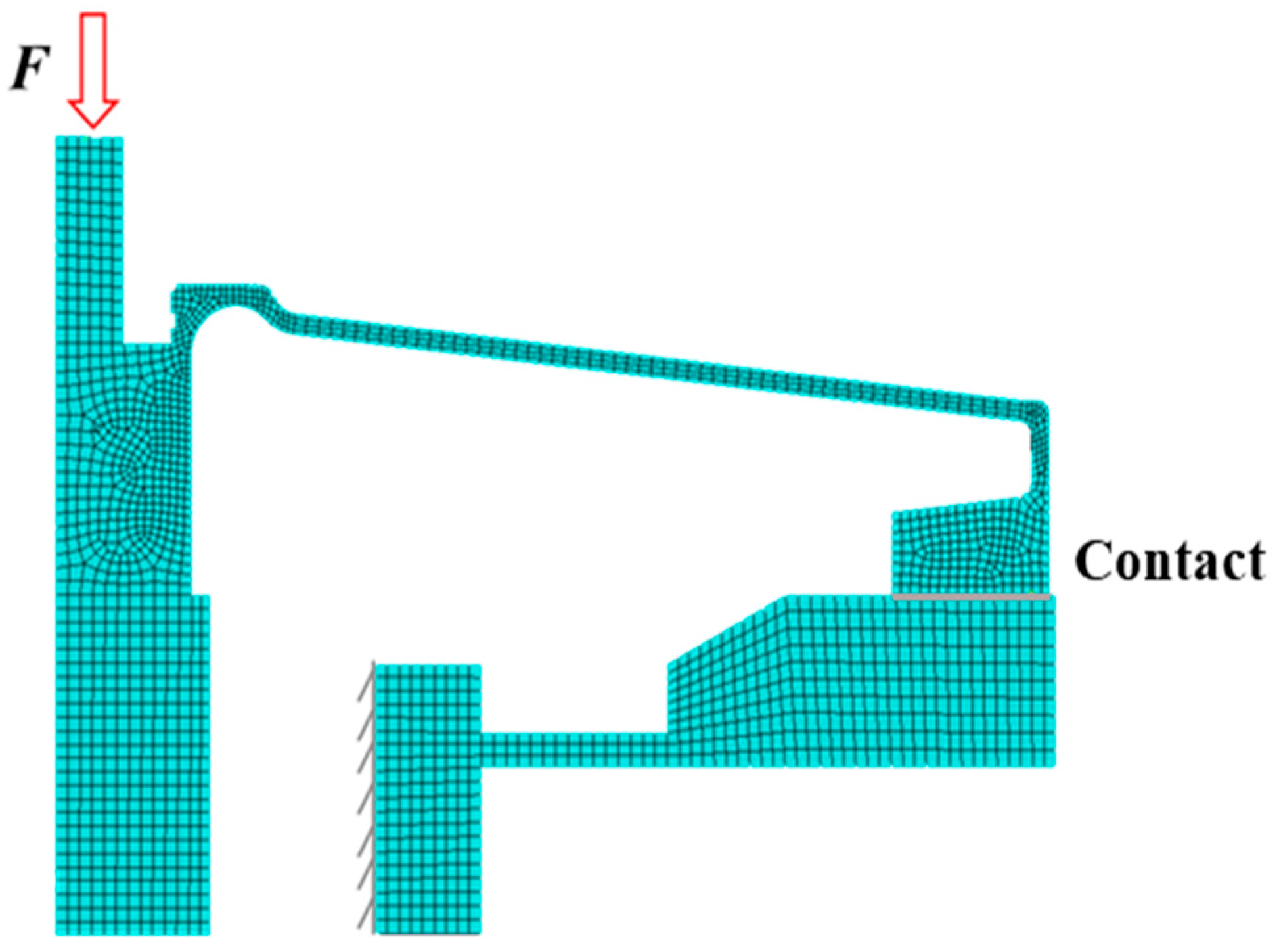
Figure 7.
Stress contour plot of the initial rotor: (a) Cross-section view; (b) Rotating body view.
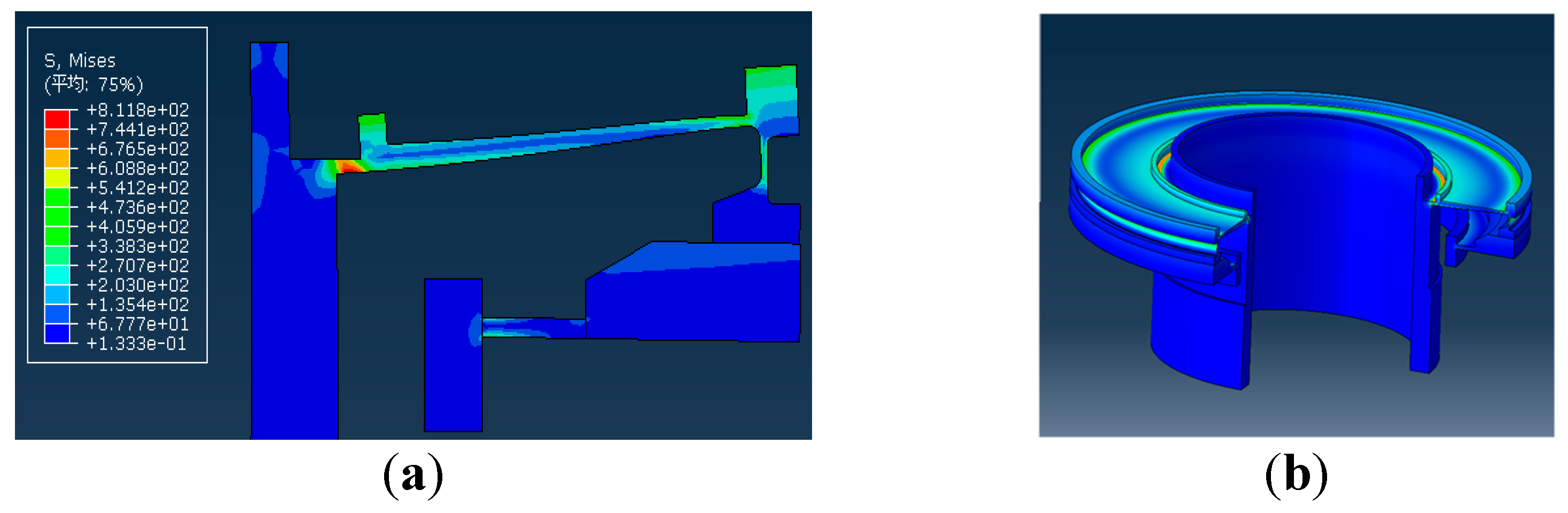
Figure 8.
Stress contour plot of proposed U-shaped rotor: (a) Cross-section view; (b) Rotating body view.
Figure 8.
Stress contour plot of proposed U-shaped rotor: (a) Cross-section view; (b) Rotating body view.
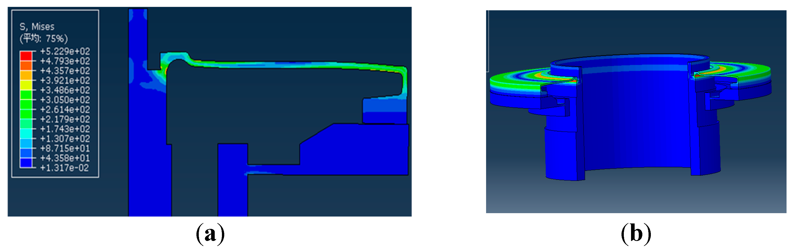
Figure 9.
Geometry configurations of the proposed U-shaped rotating body cross-section.
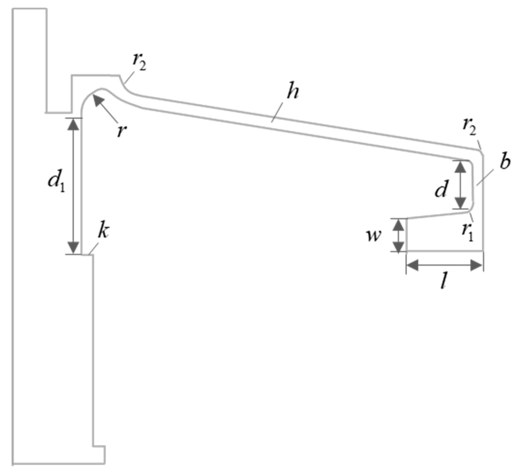
Figure 10.
The influence of at contact end on the QZS of the rotor.
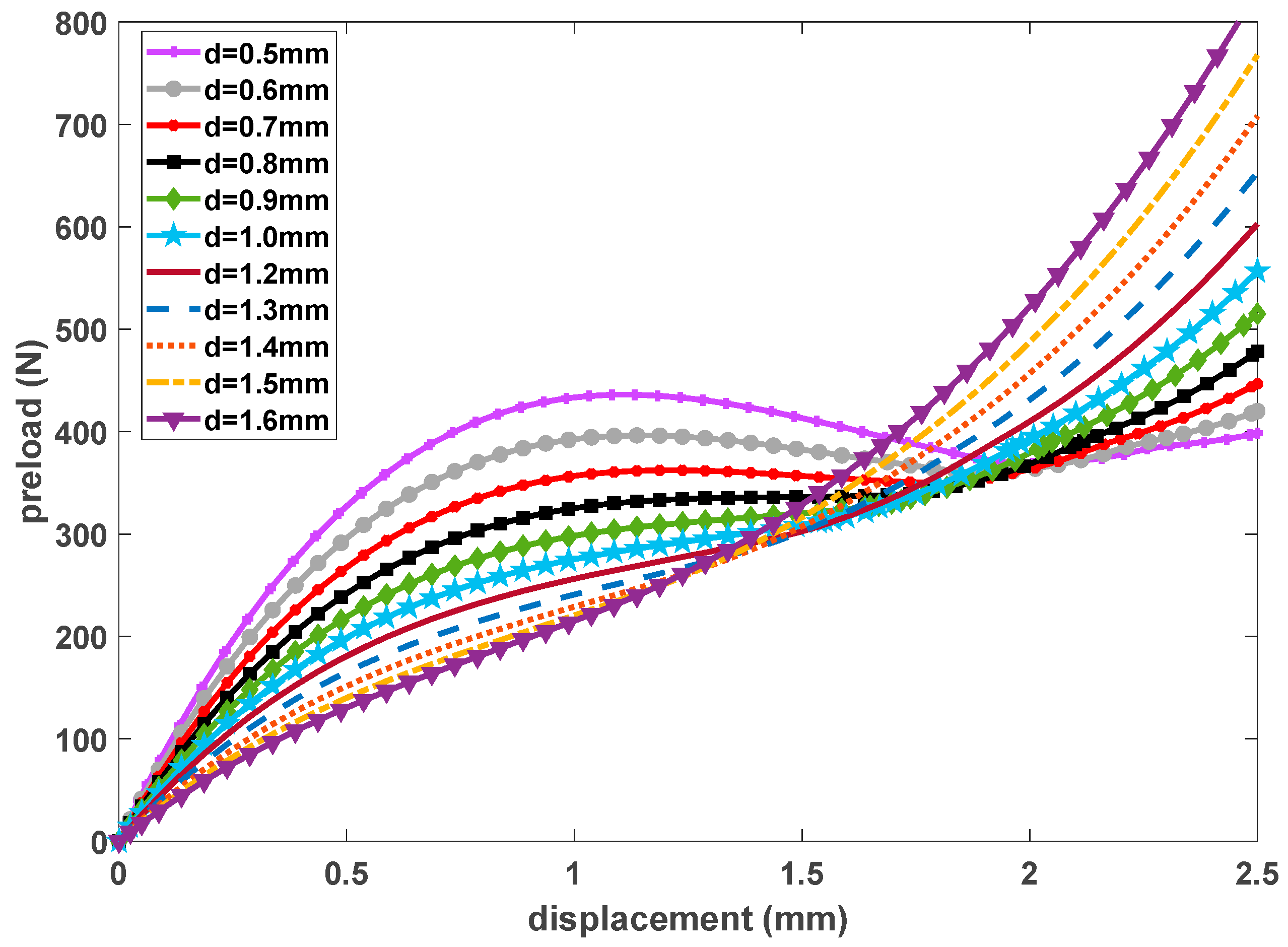
Figure 11.
The influence of on the QZS of the rotor.
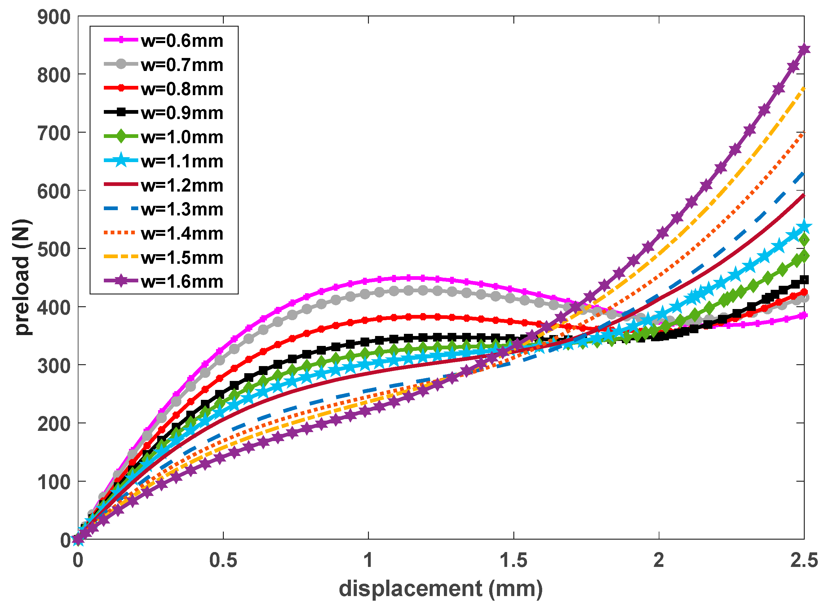
Figure 12.
The influence of at contact end on the QZS of the rotor.
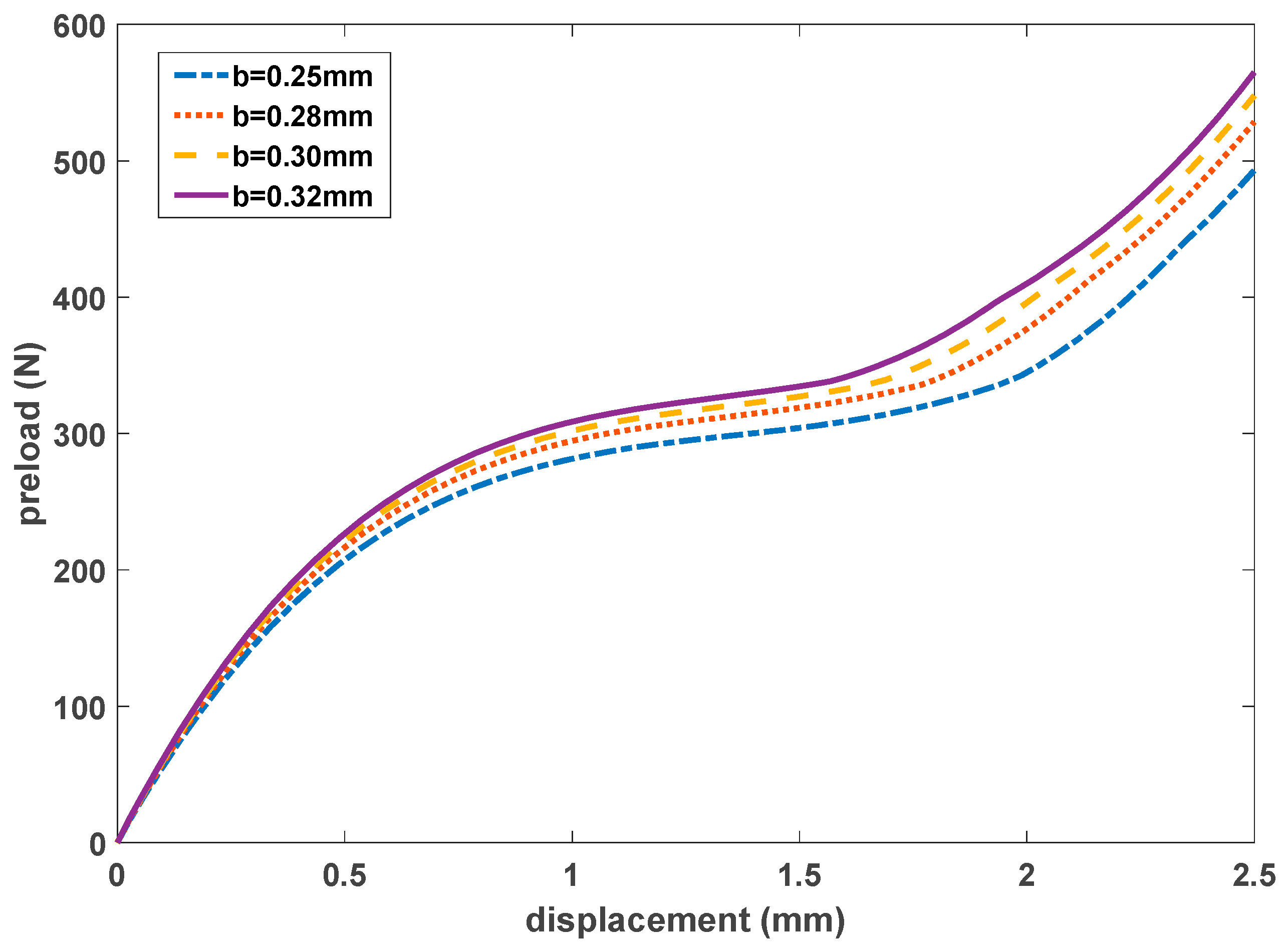
Figure 13.
The influence of at contact end on the QZS of the rotor.
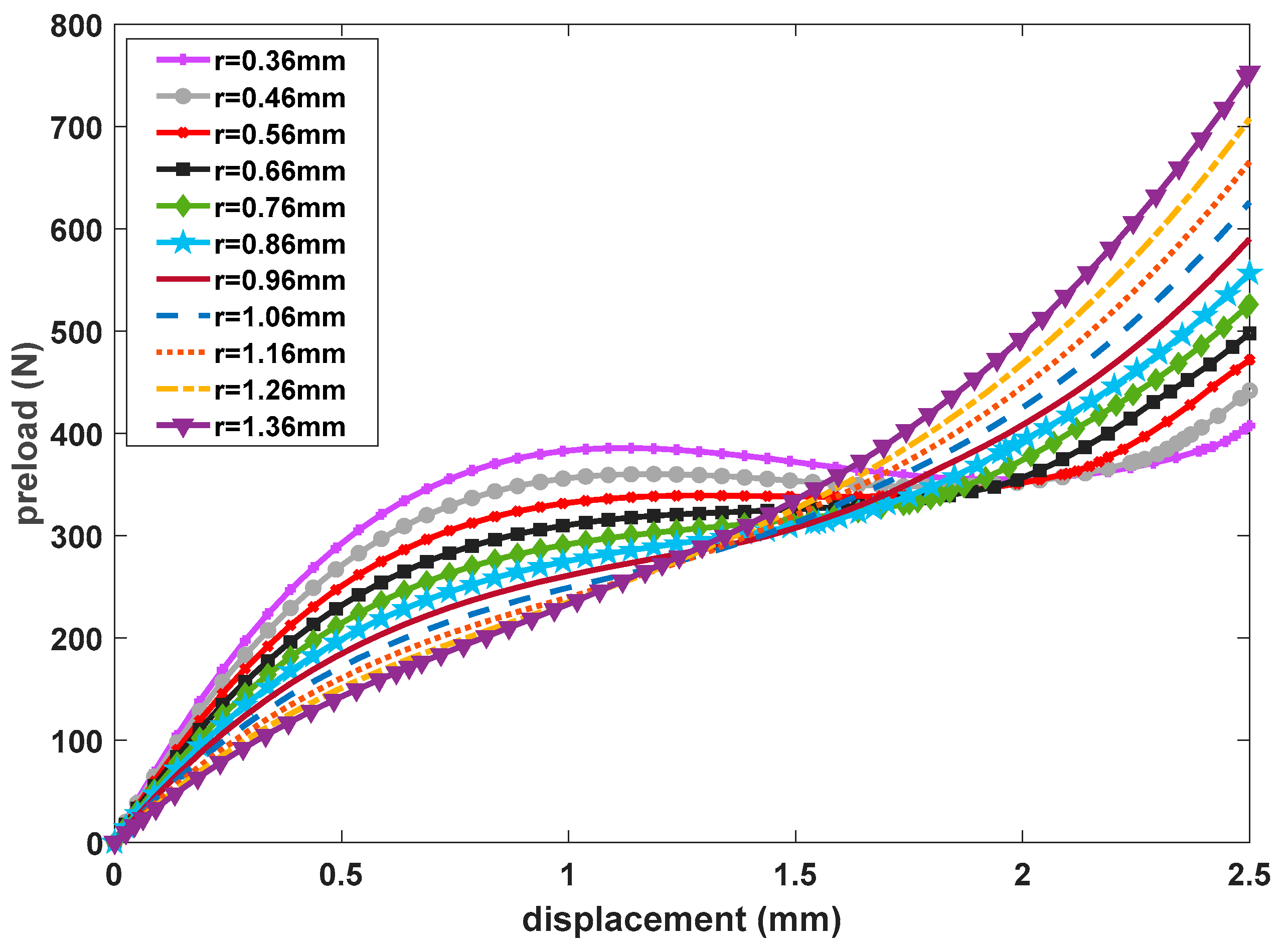
Figure 14.
The influence of at contact end on the QZS of the rotor.
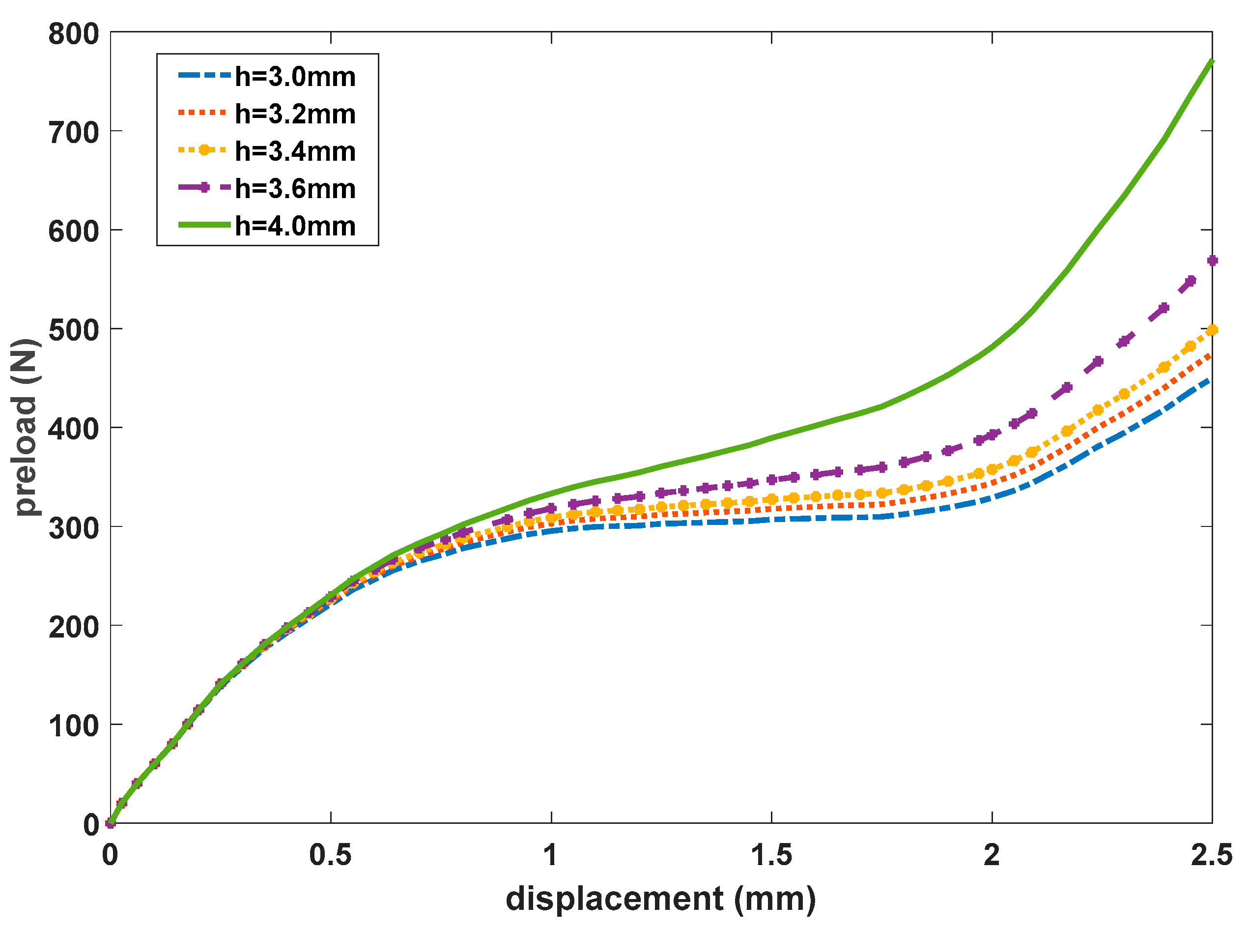
Figure 15.
Comparisons of QZS intervals by the two rotor structures.
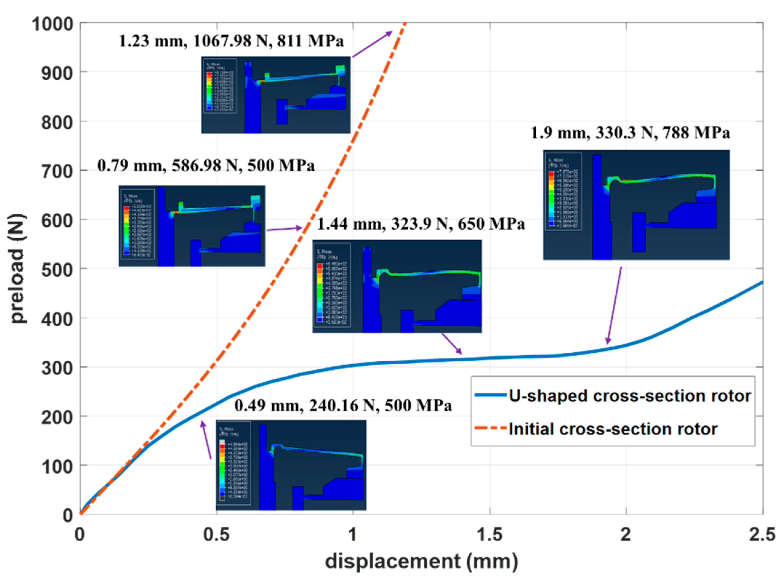
Figure 16.
Typical specimens and testing environment: (a) Test samples; (b) Schematic diagram of the testing environment.
Figure 16.
Typical specimens and testing environment: (a) Test samples; (b) Schematic diagram of the testing environment.

Figure 17.
Experiment evaluation processing.
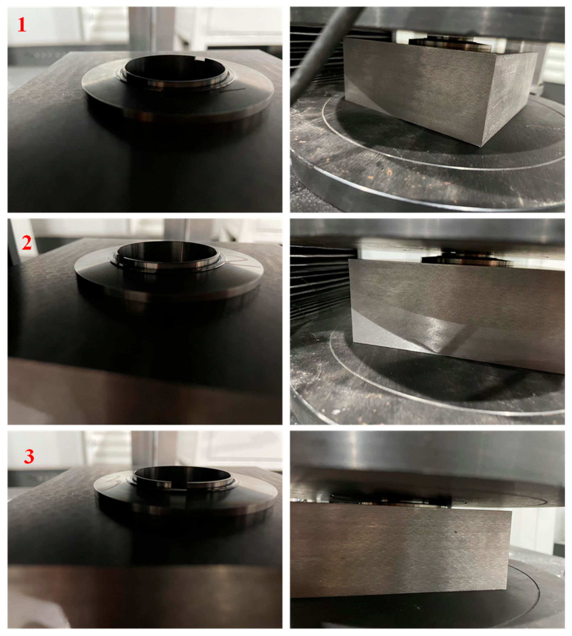
Figure 18.
Comparison of the simulation and experiment results.
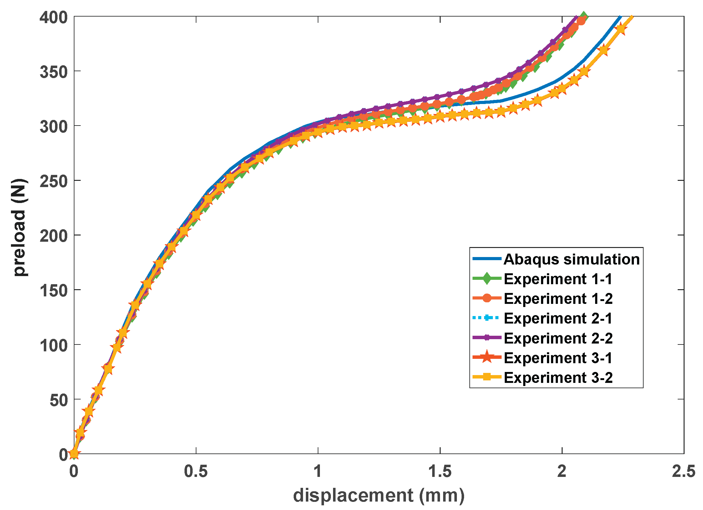

Table 1.
Independence verification of the grids.
| Mesh I | Mesh II | Mesh III | Mesh IV | |
| Number of grids | 148,000 | 201,500 | 298,500 | 405,500 |
| Mechanical response of the maximum stress (MPa) | 769.2 | 785.9 | 788.0 | 789.13 |
Table 2.
The critical control parameters of the U-shaped cross-section design (unit: mm).
| 0.9 | 1.2 | 0.3 | 0.7 | 0.32 |
Disclaimer/Publisher’s Note: The statements, opinions and data contained in all publications are solely those of the individual author(s) and contributor(s) and not of MDPI and/or the editor(s). MDPI and/or the editor(s) disclaim responsibility for any injury to people or property resulting from any ideas, methods, instructions or products referred to in the content. |
© 2026 by the authors. Licensee MDPI, Basel, Switzerland. This article is an open access article distributed under the terms and conditions of the Creative Commons Attribution (CC BY) license (http://creativecommons.org/licenses/by/4.0/).
Copyright: This open access article is published under a Creative Commons CC BY 4.0 license, which permit the free download, distribution, and reuse, provided that the author and preprint are cited in any reuse.


