
Submitted:
21 January 2026
Posted:
21 January 2026
You are already at the latest version
Abstract
Elastocaloric cooling is an emerging solid-state refrigeration technology that leverages the latent heat exchange of shape memory alloys under mechanical stress. This study inves-tigates the energy performance of a solid-to-solid elastocaloric cooling heat pump to en-hance heat transfer efficiency and overall system performance. A Matlab based numerical model, developed using the finite volume method, was employed to simulate the system. The energy performances of the elastocaloric heat pump are analyzed by varying the fre-quency of the cycle, the elastocaloric refrigerants and the types of thermal diodes, from ideal up to realistic Peltier switches. The results demonstrate that the strategic use of thermal diodes significantly improves heat flow directionality, reducing thermal losses and enhancing the efficiency of the elastocaloric cooling process. These findings contrib-ute to the development of more efficient solid-state cooling technologies, offering a viable alternative to conventional systems also for electronic circuits cooling applications.
Keywords:
elastocaloric
; numerical simulation
; solid-to-solid
; thermal diodes
1. Introduction
1.1. Generalities
The growing global demand for sustainable and high-efficiency cooling and heating technologies has brought solid-state refrigeration to the forefront of research as a viable alternative to conventional vapor-compression systems [1,2]. These traditional systems, while reliable and widespread, are increasingly scrutinized due to their environmental drawbacks, particularly the use of synthetic refrigerants with high Global Warming Potential (GWP) and Ozone Depletion Potential (ODP) [3,4]. Regulatory frameworks, such as the European F-Gas regulation 2024/573 [5] and international agreements like the Kigali Amendment to the Montreal Protocol [6,7], are progressively limiting the use of fluorinated gases, urging the development of next-generation, eco-friendly thermal management technologies.
Among the most promising alternatives are caloric materials [8], which exhibit reversible thermal effects under external fields, enabling solid-state refrigeration without harmful working fluids. Depending on the nature of the applied field, different caloric effects can be distinguished: magnetocaloric [9,10], electrocaloric [11], barocaloric [12] and elastocaloric [13,14]. Each of these effects is characterized by an adiabatic temperature change (ΔTad) or an isothermal entropy change (ΔsT), which can be exploited in thermodynamic cycles to produce heating or cooling. The elastoCaloric Effect (eCE), in particular, is observed in crystalline Shape Memory Alloys (SMAs) such as NiTi, which undergo a reversible phase transformation between austenite and martensite under applied mechanical stress [15]. This transformation is accompanied by latent heat exchange, enabling the material to release or absorb heat depending on the phase transition direction. Compared to other caloric effects, the elastocaloric effect offers large temperature changes (up to 20–25 K), high energy density, and good reversibility, making it a promising candidate for compact, efficient, and environmentally benign heat pump systems [16].
Research in this field has focused on two main fronts: the development of novel elastocaloric materials, and the design of devices capable of converting localized temperature changes into useful cooling power. Among all SMAs, NiTi-based alloys are widely regarded as the state-of-the-art, thanks to their high energy density, wide transformation range, and reasonable fatigue resistance [17]. However, issues such as thermal hysteresis, high activation stress, and functional degradation over time have led to the development of ternary and quaternary alloys like NiTiCu and NiTiCuV, which demonstrate reduced hysteresis and improved cycling stability [18].
In conventional elastocaloric devices, heat transfer is typically facilitated by a heat transfer fluid (e.g., a gas or liquid) flowing across a regenerator made of SMA elements. These systems often operate on active regeneration cycles, such as the Brayton-based Active elastocaloric Regenerative (AeR) cycle, where synchronized fluid flow and mechanical loading/unloading enhance thermal performance. Such systems, often based on wires, foils, or stacked plates, have demonstrated promising results in terms of temperature span and Coefficient Of Performance (COP), achieving ΔT > 15 K and COP values up to 6 under optimized conditions [19,20]. However, fluid-based systems face several limitations: high viscous losses in narrow channels, challenges in miniaturization, and mechanical complexity due to moving parts. To address these issues, an alternative approach based on Solid-to-Solid Heat Transfer (SSHT) has been proposed. In SSHT systems, heat is transferred directly by conduction between the elastocaloric material and adjacent solid components, eliminating the need for intermediate fluids. However, these systems pose a fundamental challenge: in the absence of forced convection, heat conduction is naturally bidirectional, lacking the inherent rectification provided by fluid flow. As a result, ensuring unidirectional heat transfer requires the integration of thermal diodes—elements or materials that exhibit anisotropic thermal conductivity and can preferentially direct heat flow [21,22]. Several recent prototypes have validated the potential of solid-state architectures. Ossmer et al. [23] developed bending-mode devices using rotating NiTi sheets, while Cheng et al. [24] introduced multi-stage elastocaloric systems based on continuous compression cycles. These systems are more compatible with compact designs and suitable for electronic cooling, where space and fluid-free operation are key constraints. Other works have explored torsional activation of elastomers (such as natural rubber) and alternative soft materials, further broadening the material landscape [25]. Furthermore, some emerging research efforts aim at integrating multicaloric effects, coupling mechanical, magnetic, or electric fields to enhance performance and reduce activation energy [26]. These hybrid concepts represent a promising frontier but still require significant material and system-level development. This configurations significantly reduces parasitic losses and enables simpler, more compact architectures. The effectiveness of heat exchange in SSHT systems, however, depends on the control of thermal flow directionality, which is inherently bidirectional in passive conductive elements.
To overcome this challenge, recent research has introduced the concept of thermal diodes—asymmetric conductive elements capable of promoting unidirectional heat transfer. When integrated into an elastocaloric SSHT system, thermal diodes can control the timing and direction of heat flow between the SMA and the heat reservoirs, mimicking the functionality of conventional valves or switches without requiring mechanical actuation. This innovation opens new avenues for the development of high-frequency, fully solid-state heat pumps.
This paper presents a numerical investigation of a novel elastocaloric heat pump architecture that combines the SSHT approach with thermal diodes. A two-dimensional finite-volume model is developed in MATLAB to simulate the thermal behavior of the system during cyclic mechanical loading. The heat pumps works with two Ni-Ti alloys (binary and the quaternary Ni-Ti-Cu-V) and implements different types of thermal diodes from ideal concept up to real Peltier elements. Key performance indicators such as temperature span, thermal power, and Coefficient Of Performance (COP) are analyzed under different operating factors. The results provide insights into the potential of solid-state caloric technologies for sustainable heating and cooling applications.
2. Elastocaloric Effect and Cycles
The elastocaloric effect is a thermomechanical phenomenon occurring in specific classes of materials—particularly shape memory alloys —under uniaxial mechanical stress. It is strongly tied to the reversible martensitic transformation between two crystallographic phases: austenite and martensite. During mechanical loading, when the applied stress exceeds a critical threshold, the SMA transitions from the high-symmetry austenitic phase to the lower-symmetry martensitic phase (A→M). This transition is associated with a release of latent heat and a decrease in the material’s entropy, leading to a temperature increase under adiabatic conditions (∆Tad,load). Upon unloading, the reverse transformation (M→A) occurs, during which latent heat is absorbed and the temperature of the material decreases (∆Tad,unload) [15].
Figure 1 illustrates the elastocaloric effect in a SMA. Panel (a) shows the stress-induced martensitic transformation and the corresponding increase in temperature, while panel (b) shows the austenitic recovery and the temperature drop that occurs during unloading [27]. At the microstructural level, these transitions involve a reorganization of the crystal lattice, leading to entropy changes that are directly responsible for the observed thermal responses.
From a thermodynamic standpoint, the isothermal entropy change ∆ST associated with the elastocaloric effect can be estimated using the following relation:
Alternatively, the adiabatic temperature change can be approximated as:
where is the initial temperature, is the specific heat at constant pressure, is the material density, and is the strain. Equation (2), while commonly used for quick estimation, assumes constant specific heat and neglects the self-heating and self-cooling phenomena that may affect the material’s thermal behavior under real adiabatic conditions [28]. A deep understanding of the thermodynamics of eCE is essential for developing efficient elastocaloric cooling cycles and modeling their performance. These formulations serve as the basis for numerical simulations of elastocaloric devices and are critical for accurately predicting energy exchanges during each phase of the cycle. The thermodynamic cycle that forms the basis of caloric cooling systems is commonly referred to as the Active elastocaloricaloric Regenerative (AeR) cycle, derived from the classical Brayton cycle. This configuration is currently the most widely studied approach for elastocaloric refrigeration operating at ambient temperature. In this setup, the elastocaloric material actively participates in the cycle, and a heat transfer fluid—typically air or water—is used to transfer thermal energy between the hot and cold reservoirs.
The AeR cycle consists of four recurring steps shown in Figure 2:
- Adiabatic application of the stress, i.e. loading;
- Heat release to a Hot Heat EXchanger (HHEX);
- Adiabatic remotion of the stress, i.e. unloading;
- Heat absorption from a Cold Heat EXchanger (CHEX).
One of the key advantages of the AeR cycle is the possibility to achieve a temperature span that exceeds the intrinsic adiabatic temperature change (ΔTad) of the SMA alone. However, this cycle also exhibits notable limitations. In particular, the high-pressure conditions required for efficient fluid motion in the regenerator cause viscous dissipation losses, which negatively affects the overall coefficient of performance. Furthermore, the cycle frequency is limited by the convective heat transfer rate between the solid and the fluid, ultimately constraining the cooling power.
An alternative approach is provided by the Solid-to-Solid Heat Transfer (SSHT) elastocaloric cycle, which addresses the drawbacks of the AeR by eliminating the need for a heat transfer fluid. In SSHT systems, heat is transferred conductively rather than convectively, enabling significantly higher operating frequencies.
The SSHT elastocaloric cycle consists of the following four phases shown in Figure 3:
I. Adiabatic increase of the applied mechanical stress;
II. Conductive heat transfer to an upper solid-state thermal mass (serving as a hot sink);
III. Adiabatic removal of the applied mechanical stress;
IV. Conductive heat absorption from a lower solid-state thermal mass (serving as a cold source).
In step (I), the temperature of the caloric material increases by ΔTad,load as a result of the elastocaloric effect. During step (II), heat is transferred conductively from the caloric material to an adjacent solid-state auxiliary material, causing a decrease in the material’s temperature. This process enables the release of thermal energy toward the hot side. In step (III), the stress is adiabatically removed, and the caloric material undergoes an additional drop in temperature, again by ΔTad,unload, due to the elastocaloric effect. Finally, in step (IV), heat is absorbed from the cold side through conductive transfer with a secondary solid element that is initially warmer, thus generating the cooling effect.
3. The system Principles and the Numerical Model
3.1. The System Principles
The proposed system aims to investigate an elastocaloric heat pump able to work both in cooling and heating mode, based on the concept of solid-to-solid heat transfer through thermal diodes. The latter is an alternative approach that avoids any mechanical movement between the caloric and auxiliary materials, employing Thermal Diodes (TDs), as shown in Figure 4.
In this setup, the central SMA (1.2 cm x 1.2 cm cross-sectional area; 0.2 cm thickness) is periodically loaded and unloaded. The upper and lower white layers act as thermal diodes (same cross-sectional area; 0.1 cm thickness) with complementary behaviors: when SMA is loaded, upper TD (TDB) is activated while lower TD (TDA) remains in OFF state. Upon unloading, the roles reverse—lower TD is in ON state while upper TD is OFF. This switching mechanism enables a directional heat flow from the cold side (CHEX) to the hot side (HHEX) without requiring mechanical motion, allowing for operation at high frequencies.
3.2. The Numerical Model And The Materials
Since in the system heat transfer occurs only through conduction, the mathematical model governing the four stages of the SSHT with thermal diode-based cycle is represented by the energy equations for the three components, as delineated in the subsequent equations:
The term in the energy equation of the caloric refrigerant represents the impact of the elastocaloric effect in the system, which is directly proportional to the adiabatic temperature change ΔTad resulting from the elastocaloric effect during loading and unloading. It is characterized as the power density produced per unit volume, represented by the following equations:
The analytical functions and are square waves opportunely set to synchronize the ON-OFF states with respect to the steps of the SSHT cycle. Specifically, as shown in Figure 5, is ON during step I (loading), whereas is ON only during step III (unloading). The thermal conductivities of TDA and TDB are function of the applied stress that is time-changing and indeed are regulated through square waves function of time, as following:
The square-waves describing the behaviour of and for an Ideal Thermal Diode (ITD) are reported in Figure 6 and Figure 7 respectively. The plotted behaviours ensure the ITDs A and B to vehiculate heat transfer in the customized steps of the SSHT cycle, i.e. KB is high in the II step to allow the heat rejection toward HHEX whereas KA is high in the IV step to activate heat absorption from CHEX. HHEX and CHEX are modelled as follows 1st type boundary conditions respectively at the bottom layer of TDA and the top layer of TDB of the system shown in Figure 4.
3.3. The Peltier Elements
To relax the assumption of ideal thermal diodes and introduce physically realizable heat-transfer elements, commercially available thermoelectric (Peltier) modules were employed as active heat-switching devices within the elastocaloric cycle. Similar approaches have been reported in the magnetocaloric literature, where Peltier modules are used to emulate diode-like heat-transfer behavior by actively controlling the direction and intensity of the heat flux [31,32,33]. In the present work, the thermoelectric modules are not intended to represent passive thermal diodes, but rather controllable heat-switch surrogates with finite thermal conductance, switching dynamics, and electrical dissipation.
Two representative Peltier modules, drawn from commercially available devices commonly used in thermal management applications, were considered and parametrized as fast and super-fast heat-switch configurations. The fast configuration, shown in Figure 8, is representative of standard modules from the TEC1-12706 series (e.g., TRU Components TEC1-12706) [34], widely used as reference thermoelectric coolers in experimental and numerical studies. The super-fast configuration is representative of lower-resistance, thinner modules such as the SKHC1-07106C (SunKool series) [35], which are designed for reduced electrical resistance and faster thermal response.
In the numerical model, according with their specifics of functioning, both the types of thermoelectric modules were characterized by the same effective thermal conductivity in the OFF state, , representative of an actively controlled low-conductance condition. The transition from OFF to ON state was modeled using a finite rise time to account for the non-instantaneous thermal response of real devices. Specifically, the super-fast Peltier cell is characterized by a rise/fall time from OFF to ON and from ON to OFF that is the half of the fast Peltier module, reflecting the reduced thermal mass and lower electrical resistance of compact thermoelectric designs of the former.
During the ON state, the thermoelectric modules provide an enhanced effective thermal conductance (), enabling directional heat transfer analogous to that of an ideal thermal diode. The electrical power absorbed by each module, including Joule heating and the Peltier contribution, was explicitly calculated and included in the energy balance:
Considering that the Peltier elements are in ON only in a portion of the entire SSHT cycle, the power consumption can be estimated as:
where D is the duty cycle evaluated as:
This electrical consumption was added to the denominator of the overall coefficient of performance, together with the mechanical work input, allowing a realistic system-level evaluation of the elastocaloric cooling efficiency.
3.4. Elastocaloric Materials
Two elastocaloric materials were considered as potential solid refrigerants for the SSHT system based on thermal diodes. The chosen materials are the shape-memory alloy Ni50.8Ti49.2 and the Ni45Ti47.2Cu5V2.75 alloy. Table 1 reports the relevant material properties, namely thermal conductivity, density, specific heat capacity at constant pressure, and the adiabatic temperature changes during loading and unloading.
3.5. Convergence of the Solving Method and the Discretization Grid
The system is solved through Finite Volume Method and a 1D numerical model has been developed in MATLAB environment. The SSHT cycle has been repeated several times and stopped when the cyclicity criterion has been met:
The effects of the discretization settings and grid convergence thresholds were examined to identify a number of nodes that ensure adequate accuracy while keeping the computational effort reasonable. The temperature profiles in two crucial points have been considered as a function of the times while the model is solved under different grid sizes: the interfaces stacked by: i) ITD_A and SMA; ii) SMA and ITD_B were used as reference metric because they are the most affected points by the evolution over the time of the numerical parameters. Figure 9 plots: the temperature trends of the (a) ITD_A-SMA and (b)SMA- ITD_B interfaces; zoom in the most sensitive time ranges for (c) ITD_A-SMA and (d)SMA- ITD_B interfaces; error percentage between different grids for (e) ITD_A-SMA and (f)SMA- ITD_B interfaces. The plots show the temperature profiles under a cycle frequency of 4 Hz as a function of the time when the model was run showing a coarse, normal and fine grid. In Figure 9(a,b) one can see the steps of the SSHT cycles. From Figure 9(c,d) one can see that the absolute difference between the peaks does not exceed 0.3 K from the course to the fine grid. Additionally from Figure 9(e,f) one can see that choosing a normal grid, the percentage errors on the interfaces do not go over 0.6%. With this threshold established, the impact of both temporal and spatial discretization was assessed. Indeed, to get a good mismatch between computational time and accuracy, the normal grid has been chosen and deemed appropriate for the subsequent simulations.
3.6. Validation of the Numerical Model with Literature Data
The numerical model developed in this work was validated against the solid-to-solid magnetocaloric model with thermal diodes presented by Cirillo et al. (2023) [39]. The same geometrical configuration, material properties, and operating conditions reported in the reference study were adopted as input for the present simulations. The validation focused on the prediction of the cold-side coefficient of performance (COP), which represents a sensitive metric for assessing the combined effects of heat transfer, caloric response, and thermal switching. Simulations were performed at three representative operating frequencies, namely 2.5 Hz, 5 Hz, and 10 Hz. Figure 10 compares the COP values obtained with the present model with those reported by Cirillo et al. (2023) for a gadolinium-based magnetocaloric system. The present model systematically overestimates the COP over the entire investigated frequency range. The relative percentage error remains below 15% at all operating points, with values of approximately 10–15%.
This systematic overestimation can be attributed to differences in numerical implementation, spatial and temporal discretization, and modeling assumptions related to heat transfer and thermal diode behavior. Nevertheless, the present model correctly reproduces both the magnitude and the monotonic trend of the COP as a function of the operating frequency. The level of agreement is considered satisfactory for the purposes of system-level analysis and supports the use of the proposed numerical framework for investigating elastocaloric SSHT configurations.
4. Results
The SSHT system was tested under different scenarios and working conditions. The scenarios are introduced along this section. As common condition for all the campaigns, the heat pump operates in cooling mode, under 5 K as ΔTlift, where TC and TH respectively are 22°C and 27°C. The tests are plotted as a function of the frequency of the cycle where:
- i)
- The first campaign of simulation has focused on analyzing the energy performances provided by the SSHT heat pump in cooling mode with ideal thermal diodes, as a function of the cycle frequency for both the elastocaloric materials under test. In this campaign ITDs with 25 W m-1K-1 are implemented.
Figure 11 shows temperature jump on cold side as a function of the frequency, evaluated as the integral media on the of the difference between the temperature of the cold heat exchanger and the temperature at the interface between the SMA and the ITDA (Ideal Thermal Diode A):
From the Figure one can observe that the two materials peak at different frequencies with different values: at 0.5 Hz the binary NiTi alloy shows a maximum of 1.82 L whereas 4.03 K is the one of the quaternary NiTiCuV, falling at 1.5 Hz. The results clearly indicate the existence of an optimal operating frequency, which is strongly influenced by the thermo-physical and caloric properties of the elastocaloric refrigerant. At low frequencies, the time available for conductive heat transfer during the solid-to-solid exchange phases is sufficiently long to ensure effective thermal interaction with the cold heat exchanger. However, the limited number of cycles per unit time increases the amount of heat accumulated, resulting in relatively low temperature jumps. As the frequency increases, the temperature jump progressively rises and reaches a maximum, reflecting a favorable balance between the intensity of the elastocaloric effect and the timing of heat transfer within the SSHT cycle. Beyond the optimal frequency, a further increase in operating frequency leads to a reduction of the temperature jump. In this regime, the time available for conductive heat transfer becomes insufficient to complete the heat rejection and absorption phases, thereby limiting the effective exploitation of the elastocaloric temperature change.
The comparison between the two materials reveals that the quaternary NiTiCuV alloy not only achieves significantly higher cold-side temperature jumps but also maintains effective cooling over a much wider frequency range than the binary NiTi alloy. Indeed the functioning of the SSHT with the NiTiCuV ensures a wider range of available frequency values (up to 15 Hz against 3 Hz proper of the former under with the system provides a cooling effect). This behavior can be attributed to the larger adiabatic temperature change and to a more favorable match between the material thermal time constants and the SSHT cycle dynamics, making the system less sensitive to frequency increases.
Same considerations can be made by observing the cooling power and the specific cooling power plotted in Figure 12(a,b). The cooling power peaks are about 6 W at 1.5 Hz for the quaternary against around 2.5 W at 0.5 Hz. Even if the power values may seem to be low (due to the small size and the reduced mass of the elastocaloric material, i.e. 0.94 g of Ni50.8Ti49.2 and 1.06 g of Ni45Ti47.2Cu5V2.75 ) the graphs showing the specific cooling power are more explanatory as it is possible to observe that the system shows a potential up to maximum of 5500 W kg-1 for Ni45Ti47.2Cu5V2.75 and of 2800 W kg-1 for Ni50.8Ti49.2. Despite the small size and reduced mass of elastocaloric elements, the system reaches remarkably high specific cooling power values, highlighting the strong potential of SSHT architectures for compact and high-power-density cooling applications.
The quaternary material is able to exploit a significantly larger fraction of its theoretical cooling potential compared to the binary NiTi alloy, indicating a more efficient conversion of the elastocaloric effect into useful cooling power. Truthy considering the above mentioned peaks of SCP, the latter consideration reflect in the heat subtracted by the system equal to 57% of the maximum upper limit (Qcold,max) if it works with Ni45Ti47.2Cu5V2.75, against only 34.6% if Ni50.8Ti49.2 is the elastocaloric material.
Figure 13 presents the Coefficient of performance in cooling mode of the SSHT evaluated as:
Figure 13 illustrates the variation of the coefficient of performance on the cold side, , as a function of the operating frequency for the SSHT elastocaloric system equipped with ideal thermal diodes and operating under a temperature lift of 5 K.
For both elastocaloric materials, the COP exhibits a monotonically decreasing trend with increasing frequency. At low frequencies, the system benefits from sufficiently long conductive heat-transfer phases, allowing an effective exploitation of the elastocaloric temperature change and resulting in high COP values. As the operating frequency increases, the duration of each SSHT phase is progressively reduced, leading to incomplete heat exchange between the elastocaloric material and the thermal reservoirs. As a consequence, the useful cooling power does not scale proportionally with frequency, while the mechanical work input per unit time increases, causing a rapid degradation of the COP. A clear performance gap is observed between the two materials. The NiTiCuV alloy consistently exhibits significantly higher COP values over the entire frequency range compared to the binary NiTi alloy. This behavior reflects the superior COPs of the quaternary alloy, characterized by a higher adiabatic temperature change and a higher material COP. When the system-level COP is compared with the material COP (), further insights can be obtained. At low operating frequencies, the SSHT system working with NiTiCuV reaches COP values of the order of 9–10, corresponding to approximately 50–55% of the material COP, with [40]. In contrast, the binary NiTi alloy reaches maximum COP values around 1.2–1.4, corresponding to approximately 20–25% of its material COP (, with [40]). As the frequency increases, the ratio decreases for both materials, indicating a progressive shift from a material-limited regime to a heat-transfer-limited regime. This effect is more pronounced for the binary NiTi alloy, whose lower intrinsic elastocaloric efficiency and less favorable thermal properties make the system more sensitive to frequency-induced limitations.
Overall, the results demonstrate that while increasing the operating frequency enhances cooling power, it inevitably penalizes efficiency. The quaternary NiTiCuV alloy mitigates this trade-off more effectively, enabling higher fractions of the material COP to be retained at the system level. Basing on the trend shown (Figs 11-13), the first campaign of simulations identifies the quaternary Ni45Ti47.2Cu5V2.75 as the most performing SMAs under test. Indeed, the next simulations only this material will be tested in the system.
- ii)
- Stemming that the quaternary NiTiCuV alloys has been chosen in the previous campaign of simulations as most performing material, the second campaign of simulations focuses on the influence of the ideal thermal diode as component for heat vechiculation: the system has been tested while mounting ITDs with different thermal conductivity: ITDs with a 2.5 times smaller thermal conductivity with respect to the former campaign were tested.
Figure 14, Figure 15 and Figure 16 investigate the influence of the thermal conductivity of the ideal thermal diodes on the performance of the SSHT elastocaloric system (, cooling and specific cooling power Figure 15(a,b), COP Figure 16), considering two representative values of the ITD conductivity, k=10 W m−1 K-1 and k=25 W m−1 K−1. A consistent trend is observed across all performance indicators.
With reference to Figure 14 one can observe an higher peak of (around 5.0 K at f=0.5 Hz), for ITD with smaller k, if compared with the 4.0 K at f=1.5 Hz of the k=25 W m-1 K-1 employed in the previous campaign. Reducing the thermal conductivity of the diode, and therefore increasing its thermal resistance, leads to higher values of the cold-side temperature jump at low operating frequencies. This behavior can be explained by the enhanced thermal confinement introduced by the higher thermal resistance, which limits parasitic heat leakage and allows a larger fraction of the elastocaloric latent heat to be retained and reutilized during subsequent phases of the cycle. In this sense, the thermal diode partially mimics the effect of a thermal regeneration, promoting internal heat reuse and increasing the achievable temperature lift. However, this improvement comes at the expense of a reduced operational frequency range. As the thermal resistance of the diode increases, the characteristic thermal time constants of the system also increase, limiting the ability of the SSHT architecture to effectively transport heat at higher frequencies. Consequently, while lower diode conductivity favors higher peaks and COP values at low frequencies, it also causes an earlier degradation of cooling power and efficiency as the frequency increases.
This trade-off is clearly reflected in the cooling power and specific cooling power trends as visible in Figure 15 (a) and (b). For higher diode conductivity (k=25 W m−1 K−1), the system is able to sustain effective heat transfer over a significantly broader frequency range, resulting in higher maximum operating frequencies and extended cooling capability. In contrast, lower conductivity diodes (k=10 W m−1 K−1), concentrate the performance in a narrow low-frequency window, where thermal confinement dominates over dynamic heat-transfer limitations.
Overall, these results highlight the dual role of the thermal diode in SSHT systems. While increasing the thermal resistance enhances temperature lift and efficiency at low frequencies by improving internal heat utilization, excessive resistance penalizes the dynamic response of the system and restricts the viable frequency range. An optimal balance between thermal confinement and heat-transfer capability is therefore required to maximize both efficiency and power density, depending on the targeted operating regime. The trade-off between operating frequency and temperature jumps shown by the ITDs for ITD with k=10 W is considered acceptable. For this reason in the next campaign of simulations the latter ITD has been compared with real Peltier cells.
- iii)
- As mentioned above, in the third campaign of simulations, two real Peltier cells types were modelled in the system to overcome the assumption of ideal thermal diodes and introduce physically realizable heat-transfer elements. Two representative Peltier modules, drawn from commercially available devices commonly used in thermal management applications, were considered, parametrized as fast and super-fast heat-switch configurations and introduced in section 3.3. As already introduced the two cells are characterized by different falling/rising ON/OFF times and an undesired small thermal conductivity during the OFF state. On the other side the thermal conductivity of the fast and superfast cells is modellable at a value around . For this reason, in this campaign of simulations the energy performances SSHT system mounting the fast and superfast Peltier elements are compared with the SSHT system performances working with ITDs with k=10
Figure 17 and Figure 18 show the temperature jumps on cold side (Figure 17), the cooling power (Figure 18(a)) and the specific cooling power (Figure 18(b)) as a function of the frequency for the ITDs and the two Peltier-based heat-switch configurations, referred to as Peltier cell 1 (super-fast) and Peltier cell 2 (fast).
Across all performance indicators, the ideal thermal diode provides the upper bound of the system performance. This behavior is expected, as the ideal diode combines finite thermal resistance during ON state and ideal insulation during OFF state with instantaneous switching and the absence of auxiliary energy consumption, allowing the elastocaloric material to be exploited under optimal heat-transfer conditions. As a result, the ideal diode configuration yields the highest cooling power, the widest operational frequency range, and the largest achievable temperature span. When the ideal diode is replaced by Peltier-based heat switches, a systematic reduction in performance is observed. For both Peltier configurations, the maximum cooling power and specific cooling power are slightly reduced, and the maximum operating frequency is shifted toward lower values. This degradation can be attributed to the finite switching dynamics of the thermoelectric modules and to the additional thermal inertia introduced by their physical structure, which limit the ability of the system to sustain effective heat transfer at higher frequencies. Despite this reduction, the Peltier-based heat switches retain a large fraction of the performance achieved with the ideal diode, particularly at low-to-intermediate frequencies. In this regime, the super-fast Peltier configuration closely follows the ideal diode trends, indicating that sufficiently short switching times allow the SSHT cycle to operate near its theoretical performance limit. The second Peltier configuration exhibits a more pronounced deviation, especially at higher frequencies, reflecting its slower effective thermal response.
The temperature jumps on cold side results further confirm this behavior. While the ideal thermal diode enables the largest peak of over an extended frequency range, both Peltier-based heat switches are still capable of producing substantial temperature lifts at low frequencies. The progressive loss of with increasing frequency highlights the growing mismatch between the thermal time constants of the heat-switching elements and the cycle period.
These findings provide a consistent basis for the subsequent evaluation of the system-level COP, shown in Figure 19 as a function of the frequency, where the auxiliary electrical consumption associated with the Peltier-based heat switches is explicitly taken into account.
The results are compared against the reference case employing an ideal thermal diode which represents the upper performance limit in the absence of additional electrical losses. As expected, the ideal thermal diode yields the highest COP over the entire frequency range, since it combines finite thermal resistance with instantaneous switching and zero electrical power consumption. When the ideal diode is replaced by Peltier-based heat switches, a systematic reduction of the COP is observed, primarily due to the inclusion of Joule losses in the system energy balance. Despite this penalty, both Peltier configurations preserve the overall shape and trends of the COP–frequency curves. At low operating frequencies, where the cooling power is maximized and the thermal cycle is less constrained by dynamic heat-transfer limitations, the COP reduction remains moderate. In this regime, the superfast Peltier cell performs closer to the ideal diode, reflecting its lower electrical resistance and reduced auxiliary power consumption. The fast Peltier cell exhibits a more pronounced COP degradation, consistent with its higher Joule losses. As the operating frequency increases, the COP decreases rapidly for all configurations, and the relative impact of the Peltier electrical consumption becomes more pronounced. At higher frequencies, the useful cooling power diminishes while the auxiliary electrical power remains approximately constant, leading to a progressive convergence of the COP curves toward zero. This behavior highlights that, in the high-frequency regime, the system performance is jointly limited by reduced heat-transfer effectiveness and by the non-negligible cost of active heat switching.
Overall, the results demonstrate that incorporating realistic Peltier-based heat switches leads to a quantitatively lower—but qualitatively consistent—COP compared to the ideal diode case. Importantly, the superfast Peltier configuration retains a significant fraction of the ideal-diode COP at low-to-moderate frequencies, confirming that thermoelectric heat switches can represent a viable and physically realistic solution for SSHT architectures, provided that their electrical consumption is carefully managed.
5. Conclusions
This work investigated the performance of a solid-state heat transfer elastocaloric cooling system based on the use of thermal diodes for directional heat-flow control. The study was motivated by the need to move beyond idealized representations of heat switches and to assess the impact of physically realistic implementations on system-level performance metrics. The analysis focused on an SSHT architecture employing elastocaloric materials coupled with thermal diodes, considering both ideal thermal diodes—modeled through an effective thermal conductivity—and Peltier-based heat switches as realistic alternatives. The system behavior was evaluated over a wide range of operating frequencies, with particular attention to cooling power, temperature span, specific cooling power, and coefficient of performance. The system was analyzed numerically using a transient one-dimensional finite-volume model implemented in MATLAB. The model accounts for conductive heat transfer within the elastocaloric elements and thermal diodes, time-dependent boundary conditions associated with the SSHT cycle, and material-specific thermophysical properties. A grid consistency analysis was performed to ensure numerical accuracy, and the auxiliary electrical consumption associated with Peltier-based heat switches was explicitly included in the system-level COP evaluation.
Based on the results obtained, the following conclusions can be drawn:
- the SSHT elastocaloric system exhibits a strong dependence on operating frequency, with cooling power and cold temperature span maximized at low frequencies and progressively degraded at higher frequencies due to limited heat-transfer time within each cycle.
- Thermal diode properties play a critical role in shaping system performance. Lower effective thermal conductivity enhances thermal confinement and increases the achievable temperature span at low frequencies, but at the cost of a reduced operational frequency range due to increased thermal resistance.
- Ideal thermal diodes provide an upper bound for system performance, enabling the highest cooling power, temperature span, and COP by eliminating switching delays and auxiliary energy consumption.
- When realistic Peltier-based heat switches are considered, a systematic reduction in performance is observed, primarily associated with finite switching dynamics and Joule losses introduced by the electrical driving of the thermoelectric modules.
- Despite these penalties, Peltier-based heat switches preserve the qualitative trends of the ideal-diode case and retain a significant fraction of the achievable performance, particularly in the low-to-moderate frequency regime.
- The electrical consumption of the Peltier modules has a limited impact on performance at low frequencies, where cooling power is relatively high, but becomes increasingly dominant at higher frequencies, leading to a rapid degradation of the system-level COP.
- Faster thermoelectric heat switches with lower electrical resistance consistently outperform slower alternatives, highlighting switching speed and electrical efficiency as key design parameters for practical SSHT implementations.
The combination of moderate operating temperature spans (of the order of a few kelvin), cooling powers in the range of several watts, and compact solid-state architecture makes the proposed SSHT system particularly suitable for the thermal management of electronic components, where localized cooling, reliability, and the absence of moving parts are critical requirements.
Author Contributions
For research articles with several authors, a short paragraph specifying their individual contributions must be provided. The following statements should be used “Conceptualization, L.C., A.G., C.M., V.O.; methodology, L.C, A.G., C.M.; software, L.C, C.M.; validation, V.O.; formal analysis, L.C, A.G., C.M., V.O; investigation, V.O, L.V., L.C., S.G.; data curation, V.O, L.V., L.C.; writing—original draft preparation, L.C, and C.M.; visualization, L.C, S.G., A.G., C.M., V.O, L.V; supervision, L.C., A.G. and C.M.; project administration, A.G.; funding acquisition, L.C. All authors have read and agreed to the published version of the manuscript.”.
Funding
“This research was funded by National Recovery and Resilience Plan (NRRP), Mission 4 Component 2 Investment 1.3 - Call for tender No. 1561 of 11.10.2022 of Ministero dell’Università e della Ricerca (MUR). European Union – NextGenerationEU. Award Number: Project code PE0000021, Concession Decree No. 1561 of 11.10.2022 adop-ted by Ministero dell’Università e della Ricerca (MUR), CUP E63C22002160007 - Project title “Network 4 Energy Sustainable Transition – NEST”.
Data Availability Statement
Data are available on request.
Conflicts of Interest
“The authors declare no conflicts of interest.”.
Nomenclature
| Roman symbols | |
| an | analytical function |
| C | specific heat capacity, J kg-1 K-1 |
| COP | Coefficient Of Performance, - |
| D | Duty cycle, - |
| k | Thermal conductivity, W m-1 K-1 |
| I | Electrical current, A |
| Thermal power, W | |
| R | Electrical resistance of the Peltier module, Ω |
| s | entropy, J kg-1 K-1 |
| SCP | Specific Cooling Power, W kg-1 |
| T | temperature, K |
| t | time, s |
| Heat source due to elastocaloric effect, W m-3 | |
| V | Electrical tension, V |
| Input power to the system, W | |
| x | longitudinal spatial coordinate, m |
| y | orthogonal spatial coordinate, m |
| Greek symbols | |
| α | Total Seebeck effect of the Peltier module, VK-1 |
| Δ | Finite difference |
| strain, m | |
| Infinitesimal quantity | |
| density, kg m-3 | |
| Stress, MPa | |
| Subscripts | |
| 0 | Initial |
| 1 | final |
| A | thermal diode A |
| ad | adiabatic |
| B | thermal diode B |
| cold | cooling |
| cycle | duration of the entire SSHT cycle |
| el | elastocaloric |
| hot | heating |
| load | loading |
| M | material |
| OFF | OFF state |
| ON | ON state |
| p | constant pressure |
| Peltier | proper of the Peltier element |
| s | solid |
| T | constant temperature |
| unload | unloading |
| Acronyms | |
| AeR | Active elastocaloric Regenerative |
| CHEX | Cold Heat EXchanger |
| COP | Coefficient Of Performance |
| eCE | elastoCaloric Effect |
| GWP | Global Warming Potential |
| HHEX | Hot Heat EXchanger |
| ITD | Ideal Thermal Diode |
| ODP | Ozone Depletion Potential |
| SMA | Shape Memory Alloy |
| SSHT | Solid-to-Solid Heat Transfer |
| TD | Thermal Diode |
References
- Elsayad, M. M.; Djuansjah, J.; Ataya, S.; Jang, S. H.; Meng, A.; Abdelgaied, M.; Sharshir, S. W. Case studies on elastocaloric technology-based solid-state cooling: A focus on materials and applications. Case Studies in Thermal Engineering 2025, 75, 107251. [Google Scholar] [CrossRef]
- Report of International Energy Agency (IEA). The Future of Cooling; 2018. [Google Scholar]
- Reshniak, V.; Cheekatamarla, P.; Sharma, V.; Yana Motta, S. A review of sensing technologies for new, low global warming potential (gwp), flammable refrigerants. Energies 2023, 16(18), 6499. [Google Scholar] [CrossRef]
- Tsai, W. T.; Tsai, C. H. A survey on fluorinated greenhouse gases in Taiwan: emission trends, regulatory strategies, and abatement technologies. Environments 2023, 10(7), 113. [Google Scholar] [CrossRef]
- Regulation (EU) 2024/573 of the European Parliament and of the Council of 7 February 2024 on fluorinated greenhouse gases, amending Directive (EU) 2019/1937 and repealing Regulation (EU) No 517/2014.
- Protocol, M. Montreal protocol on substances that deplete the ozone layer. Washington, DC: US Government Printing Office 1987, 26, 128–136. [Google Scholar]
- Heath, E. A. Amendment to the Montreal protocol on substances that deplete the ozone layer (Kigali amendment). International Legal Materials 2017, 56(1), 193–205. [Google Scholar] [CrossRef]
- Moya, X.; Mathur, N. D. Caloric materials for cooling and heating. Science 2020, 370(6518), 797–803. [Google Scholar] [CrossRef] [PubMed]
- Zarkevich, N. A.; Zverev, V. I. Viable materials with a giant magnetocaloric effect. Crystals 2020, 10(9), 815. [Google Scholar] [CrossRef]
- Fitta, M.; Pełka, R.; Konieczny, P.; Bałanda, M. Multifunctional molecular magnets: Magnetocaloric effect in octacyanometallates. Crystals 2018, 9(1), 9. [Google Scholar] [CrossRef]
- Lu, B.; Jian, X.; Lin, X.; Yao, Y.; Tao, T.; Liang, B.; Lu, S. G. Enhanced electrocaloric effect in 0.73 Pb (Mg1/3Nb2/3) O3-0.27 PbTiO3 single crystals via direct measurement. Crystals 2020, 10(6), 451. [Google Scholar] [CrossRef]
- Mikhaleva, E. A.; Flerov, I. N.; Gorev, M. V.; Bondarev, V. S.; Bogdanov, E. V. Features of the behavior of the barocaloric effect near ferroelectric phase transition close to the tricritical point. Crystals 2020, 10(1), 51. [Google Scholar] [CrossRef]
- Panchenko, E. Y.; Yanushonite, E. I.; Eftifeeva, A. S.; Tokhmetova, A. B.; Kurlevskaya, I. D.; Tagiltsev, A. I.; Chumlyakov, Y. I. Elastocaloric effect in aged single crystals of Ni54Fe19Ga27 ferromagnetic shape memory alloy. Metals 2022, 12(8), 1398. [Google Scholar] [CrossRef]
- Shi, Y.; Li, B. Influence of Stress on the Chiral Polarization and Elastrocaloric Effect in BaTiO3 with 180° Domain Structure. Crystals 2024, 14(6), 511. [Google Scholar] [CrossRef]
- Mañosa, L.; Planes, A. Elastocaloric effect in shape-memory alloys. Shape Memory and Superelasticity 2024, 10(2), 89–98. [Google Scholar] [CrossRef]
- Tušek, J.; Engelbrecht, K.; Millán-Solsona, R.; Mañosa, L.; Vives, E.; Mikkelsen, L. P.; Pryds, N. The Elastocaloric Effect: A Way to Cool Efficiently. Advanced Energy Materials 2015, (13). [Google Scholar] [CrossRef]
- Zuo, C.; Zheng, L.; Yang, S.; Li, B.; Zhang, H. The current research status and development of elastocaloric refrigeration based on NiTi alloys. Next Materials 2024, vol. 5, 100270. [Google Scholar] [CrossRef]
- Chluba, C.; Ge, W.; Lima de Miranda, R.; Strobel, J.; Kienle, L.; Quandt, E.; Wuttig, M. Ultralow-fatigue shape memory alloy films. Science 2015, 348(6238), 1004–1007. [Google Scholar] [CrossRef]
- Schmidt, M.; Schütze, A.; Seelecke, S. Scientific test setup for investigation of shape memory alloy based elastocaloric cooling processes. International Journal of Refrigeration 2015, 54, 88–97. [Google Scholar] [CrossRef]
- Kabirifar, P.; Žerovnik, A.; Ahčin, Ž.; Porenta, L.; Brojan, M.; Tušek, J. Elastocaloric cooling: state-of-the-art and future challenges in designing regenerative elastocaloric devices. Journal of Mechanical Engineering/Strojniški Vestnik 2019, 65. [Google Scholar] [CrossRef]
- Tso, C. Y.; Chao, C. Y. Solid-state thermal diode with shape memory alloys. International Journal of Heat and Mass Transfer 2016, 93, 605–611. [Google Scholar] [CrossRef]
- Bruederlin, F.; Bumke, L.; Chluba, C.; Ossmer, H.; Quandt, E.; Kohl, M. Elastocaloric cooling on the miniature scale: a review on materials and device engineering. Energy Technology 2018, 6(8), 1588–1604. [Google Scholar] [CrossRef]
- Bruederlin, F.; Ossmer, H.; Wendler, F.; Miyazaki, S.; Kohl, M. SMA foil-based elastocaloric cooling: from material behavior to device engineering. Journal of Physics D: Applied Physics 2017, 50(42), 424003. [Google Scholar] [CrossRef]
- Cheng, S.; Xiao, Y.; Li, X.; Lin, H.; Hua, P.; Sheng, L. Continuous rotating bending NiTi sheets for elastocaloric cooling: Model and experiments. International Journal of Refrigeration 2023, 147, 39–47. [Google Scholar] [CrossRef]
- Zheng, J., Li, Z., Lv, C., Li, G., Huo, X., Wang, B., ... & Hou, H. Twistocaloric effect versus elastocaloric effect in shape memory alloys for low-force mechanocaloric design. Journal of Physics D: Applied Physics 2024, 58(7), 075503. [CrossRef]
- Czernuszewicz, A.; Kaleta, J.; Lewandowski, D. Multicaloric effect: Toward a breakthrough in cooling technology. Energy conversion and management 2018, 178, 335–342. [Google Scholar] [CrossRef]
- Qian, S.; Ling, J.; Hwang, Y.; Radermacher, R.; Takeuchi, I. Thermodynamics cycle analysis and numerical modeling of thermoelastic cooling systems. International Journal of Refrigeration 2015, 56, 65–80. [Google Scholar] [CrossRef]
- Tušek, J.; Engelbrecht, K.; Mañosa, L.; Vives, E.; Pryds, N. Understanding the thermodynamic properties of the elastocaloric effect through experimentation and modelling. Shape Memory and Superelasticity 2016, 2(4), 317–329. [Google Scholar] [CrossRef]
- Ossmer, H.; Kohl, M. Elastocaloric cooling: Stretch to actively cool. Nature Energy 2016, 1(10), 1–2. [Google Scholar] [CrossRef]
- Kitanovski, A.; Egolf, P. W. Innovative ideas for future research on magnetocaloric technologies. International journal of refrigeration 2010, 33(3), 449–464. [Google Scholar] [CrossRef]
- de Vries, W.; van der Meer, T. H. Application of Peltier thermal diodes in a magnetocaloric heat pump. Applied Thermal Engineering 2017, 111, 377–386. [Google Scholar] [CrossRef]
- Mannella, G. A.; La Carrubba, V.; Brucato, V. Peltier cells as temperature control elements: Experimental characterization and modeling. Applied thermal engineering 2014, 63(1), 234–245. [Google Scholar] [CrossRef]
- Tomc, U.; Tušek, J.; Kitanovski, A.; Poredoš, A. A numerical comparison of a parallel-plate AMR and a magnetocaloric device with embodied micro thermoelectric thermal diodes. International journal of refrigeration 2014, 37, 185–193. [Google Scholar] [CrossRef]
- TEC1-12706 datasheet. Available online: https://peltiermodules.com/peltier.datasheet/TEC1-12706.pdf.
- SKHC1-07106C datasheet. Available online: https://www.digikey.com/en/products/detail/sheetak/SKHC1-071-06-C-T100-NS-TF00-ALO/12153420.
- Zhou, M.; Li, Y.; Zhang, C.; Li, S.; Wu, E.; Li, W.; Li, L. The elastocaloric effect of Ni50. 8Ti49. 2 shape memory alloys. Journal of Physics D: Applied Physics 2018, 51(13), 135303. [Google Scholar] [CrossRef]
- Wieczorek, A.; Frenzel, J.; Schmidt, M.; Maaß, B.; Seelecke, S.; Schütze, A.; Eggeler, G. Optimizing Ni–Ti-based shape memory alloys for ferroic cooling. Functionals Materials Letters 2017, vol. 10(n. 01), 1740001. [Google Scholar] [CrossRef]
- Schmidt, M.; Kirsch, S.M.; Seelecke, S.; Schütze, A. Elastocaloric cooling: From fundamental thermodynamics to solid state air conditioning. Science and Technology for the Built Environment 2016, 2374–4731. [Google Scholar] [CrossRef]
- Cirillo, L.; Greco, A.; Masselli, C. A Solid-to-Solid 2D Model of a Magnetocaloric Cooler with Thermal Diodes: A Sustainable Way for Refrigerating. Energies 2023, 16(13), 5095. [Google Scholar] [CrossRef]
- Borzacchiello, A.; Cirillo, L.; Greco, A.; Masselli, C. A comparison between different materials with elastocaloric effect for a rotary cooling prototype. Applied Thermal Engineering 2023, 235, 121344. [Google Scholar] [CrossRef]
Figure 1.
The forward and reverse austenite-martensite transformation [27].
Figure 1.
The forward and reverse austenite-martensite transformation [27].
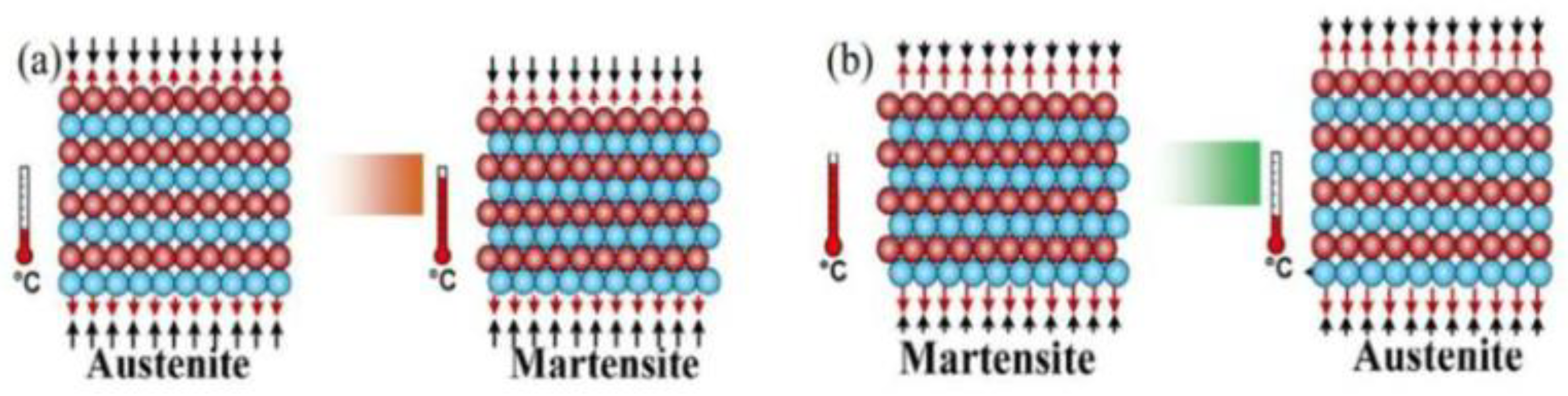
Figure 2.
The four steps of the AeR cycle [29].
Figure 2.
The four steps of the AeR cycle [29].
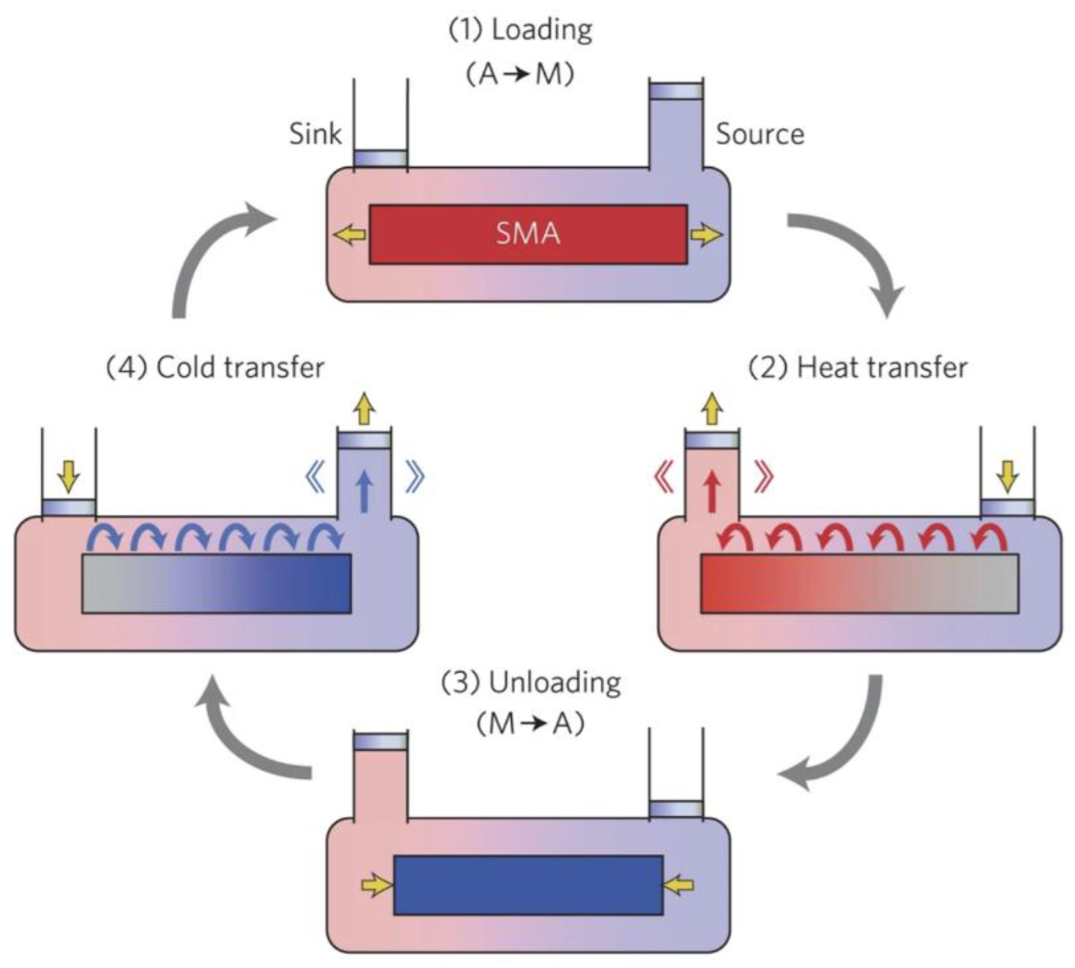
Figure 3.
The four steps of the SSHT cycle [30].
Figure 3.
The four steps of the SSHT cycle [30].
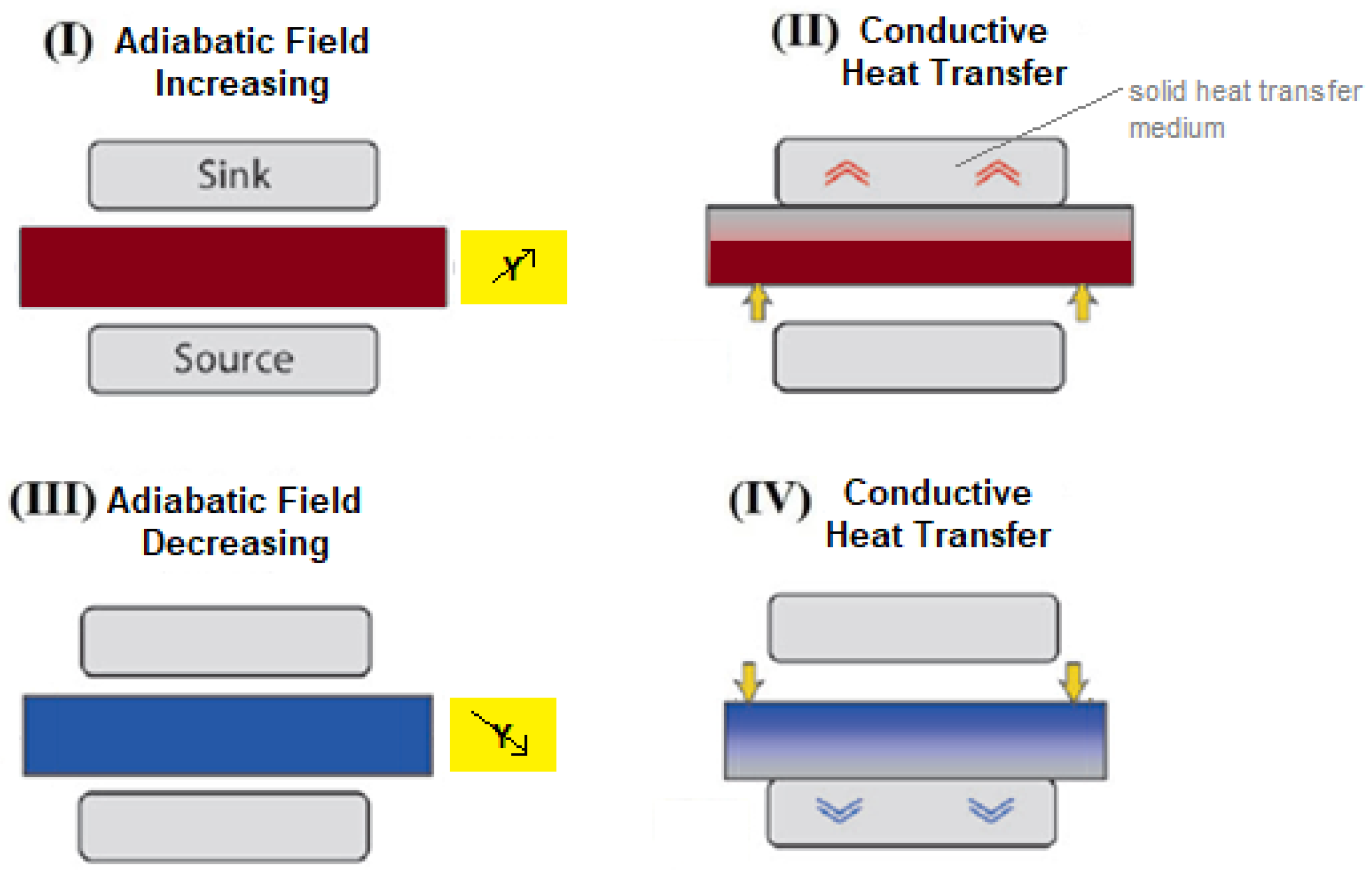
Figure 4.
Heat releasing toward HHEX and heat absorption from CHEX through TDs .
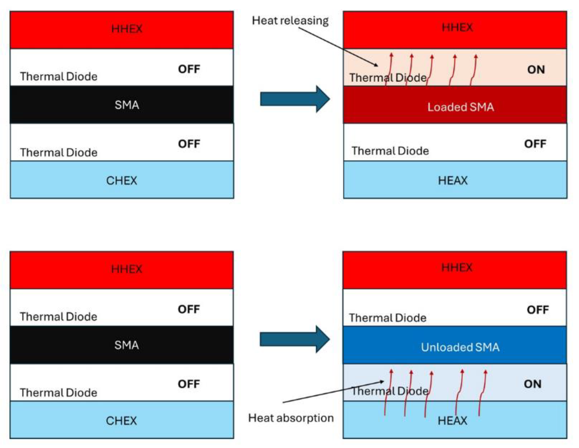
Figure 5.
The U’ function modelling elastocaloric effect during one SSHT cycle .
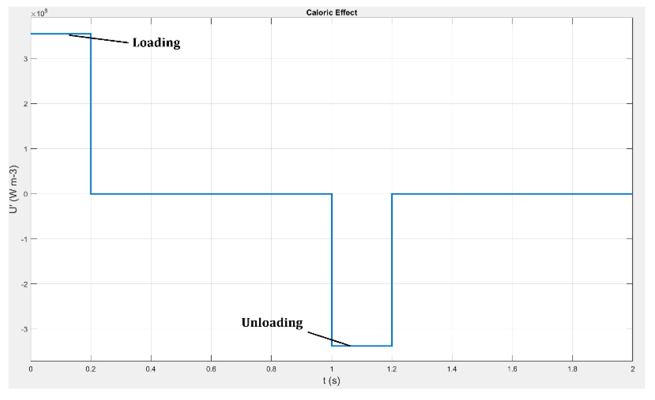
Figure 6.
The KA function modelling the ITD A thermal conductivity during SSHT cycle .
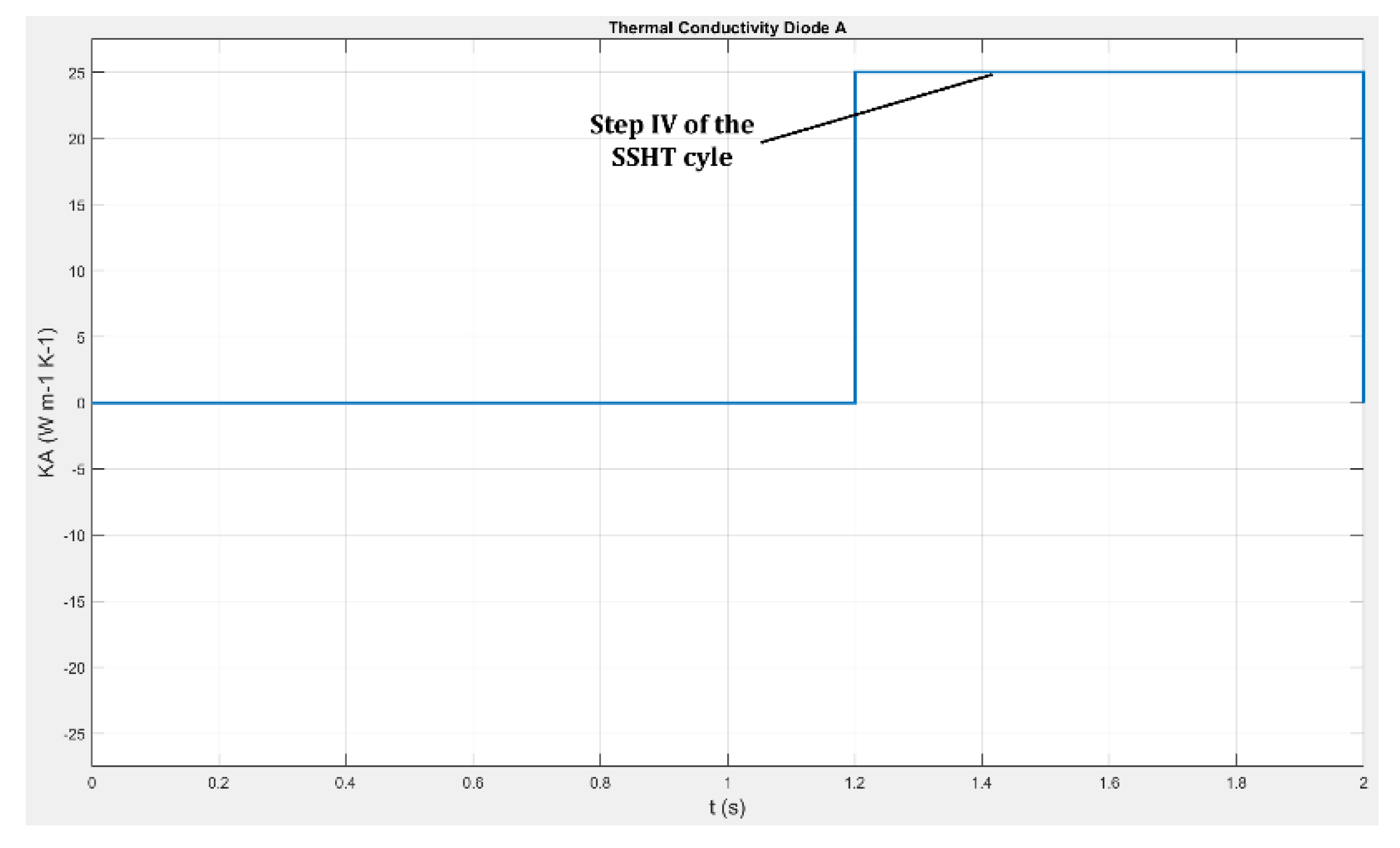
Figure 7.
The KB function modelling the ITDB thermal conductivity during SSHT cycle .
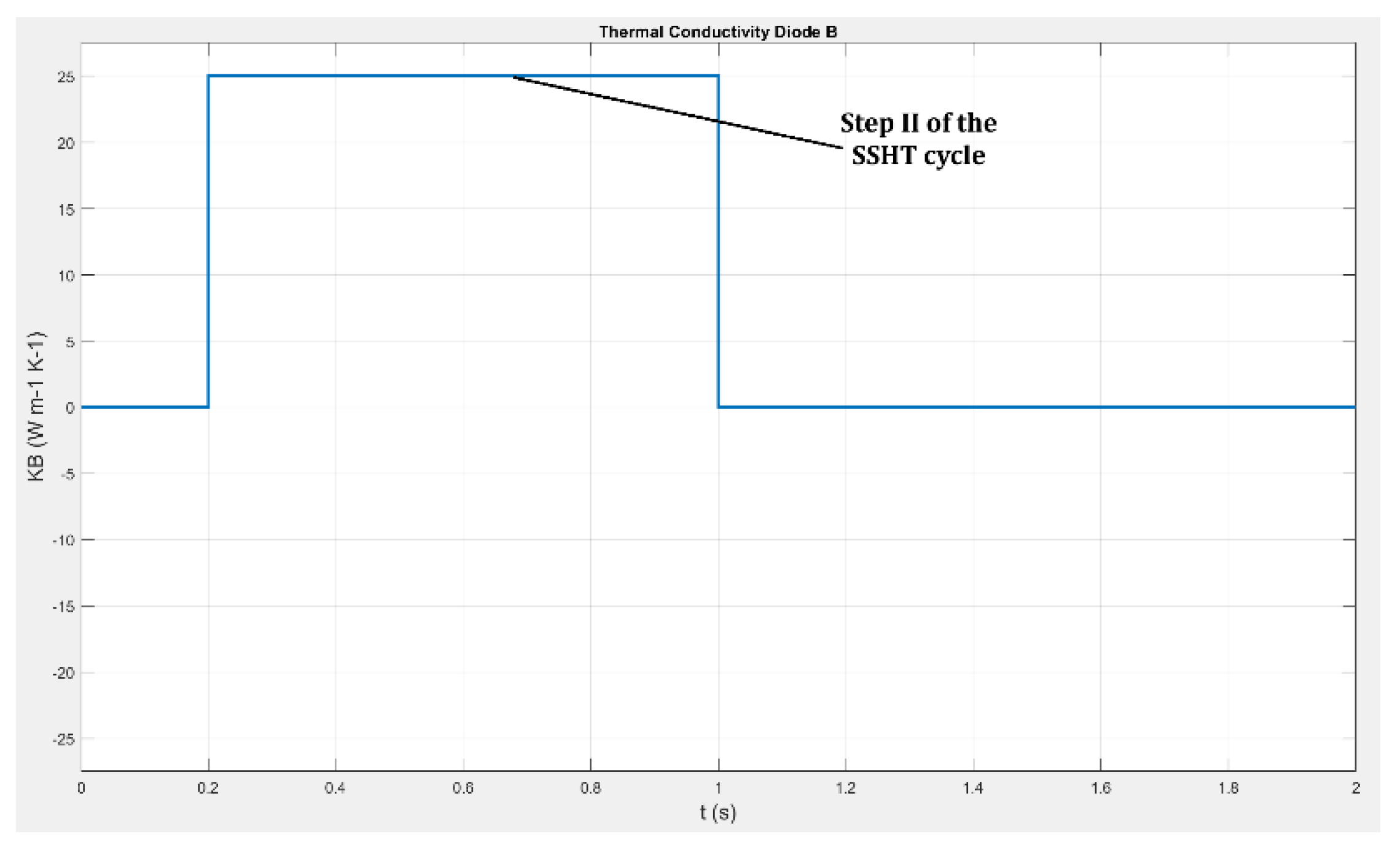
Figure 8.
The TEC1-12706 fast Peltier Cell: (a) the component ; (b) the design schematization.
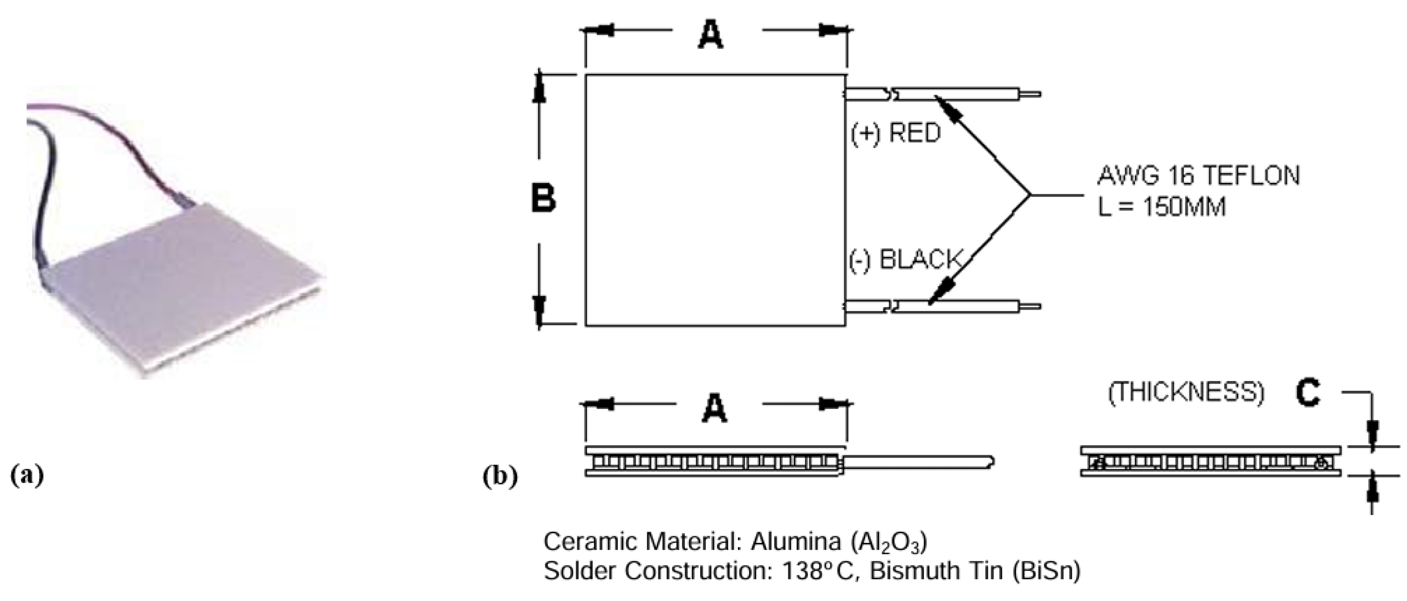
Figure 9.
Grid consistence analysis: the temperature trends of the (a) ITD_A-SMA and (b) SMA- ITD_B interfaces; zoom in the most sensitive time ranges for (c) ITD_A-SMA and (d) SMA- ITD_B interfaces; error percentage between different grids for (e) ITD_A-SMA and (f) SMA- ITD_B interfaces.
Figure 9.
Grid consistence analysis: the temperature trends of the (a) ITD_A-SMA and (b) SMA- ITD_B interfaces; zoom in the most sensitive time ranges for (c) ITD_A-SMA and (d) SMA- ITD_B interfaces; error percentage between different grids for (e) ITD_A-SMA and (f) SMA- ITD_B interfaces.
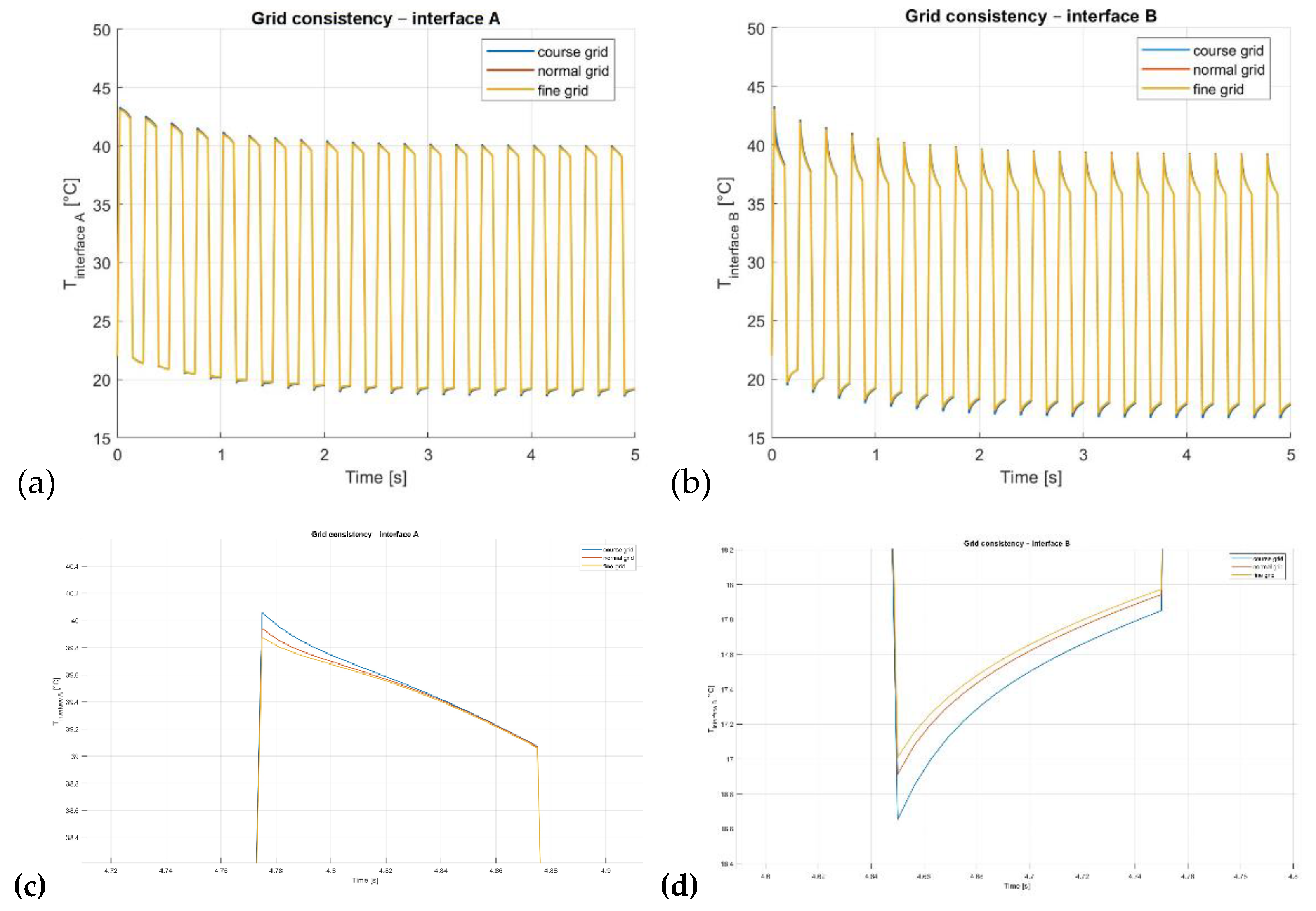
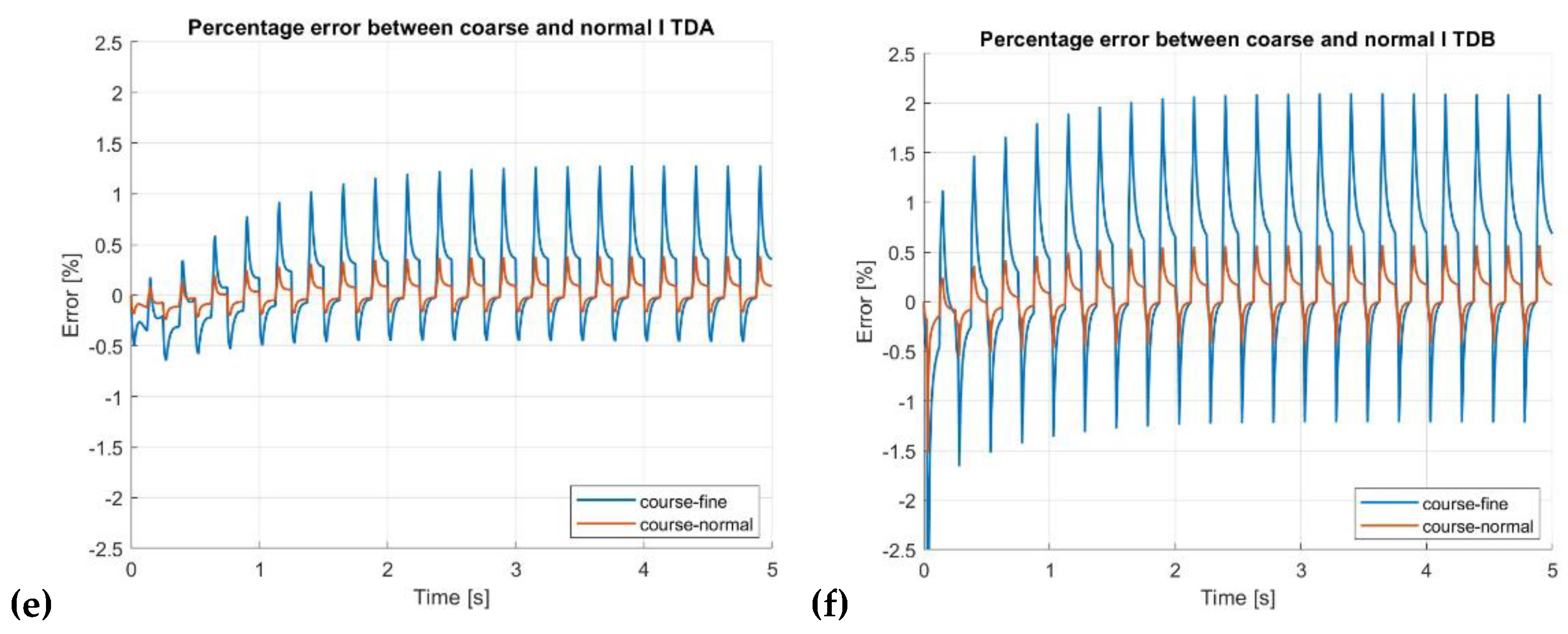
Figure 10.
Validation of the present numerical model against the results of Cirillo et al. (2023) for a gadolinium-based magnetocaloric system with thermal diodes.
Figure 10.
Validation of the present numerical model against the results of Cirillo et al. (2023) for a gadolinium-based magnetocaloric system with thermal diodes.
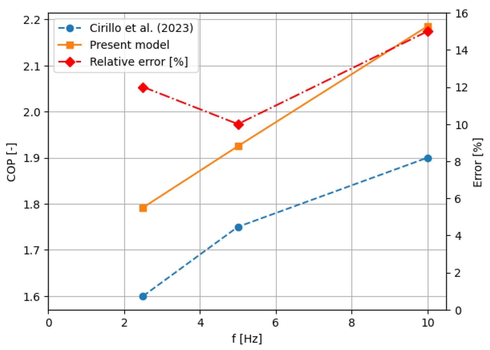
Figure 11.
Temperature jumps on cold side as a function of the cycle frequency for different elastocaloric materials and the SSHT system working with ITDs with kON=25 W m-1K-1.
Figure 11.
Temperature jumps on cold side as a function of the cycle frequency for different elastocaloric materials and the SSHT system working with ITDs with kON=25 W m-1K-1.
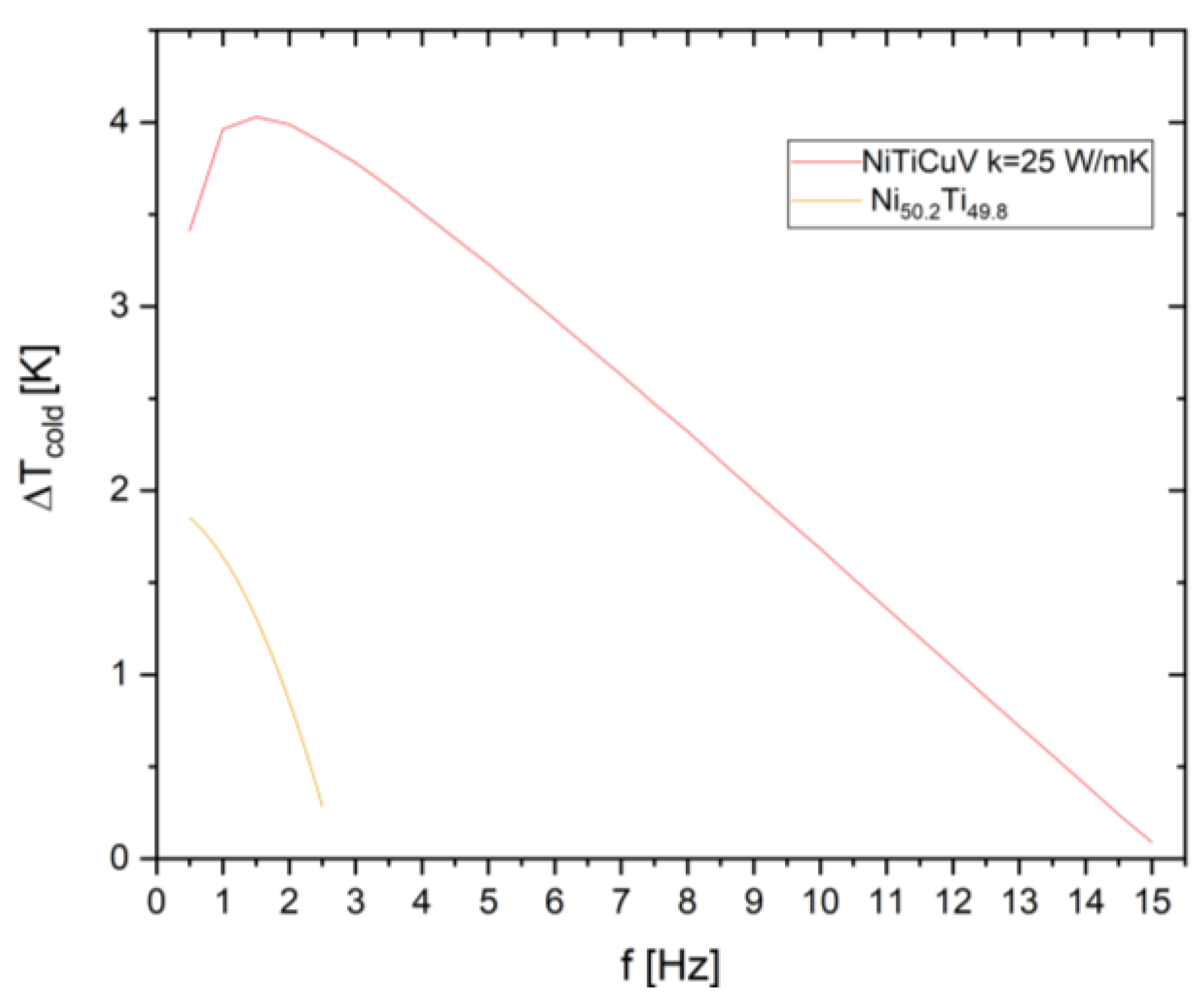
Figure 12.
(a) Cooling power and (b) specific cooling power as a function of the cycle frequency for different elastocaloric materials and the SSHT system working with ITDs with kON=25 W m-1K-1.
Figure 12.
(a) Cooling power and (b) specific cooling power as a function of the cycle frequency for different elastocaloric materials and the SSHT system working with ITDs with kON=25 W m-1K-1.
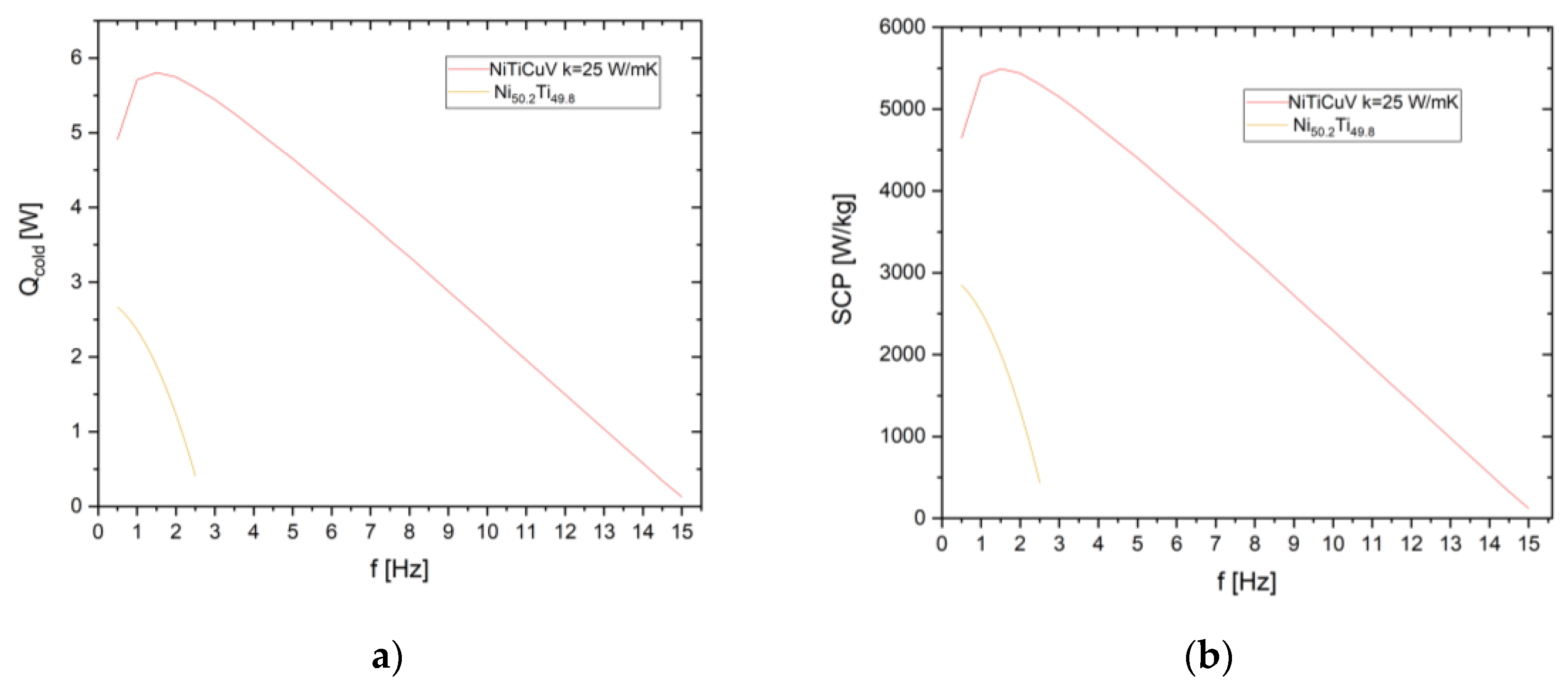
Figure 13.
Coefficient of Performance as a function of the cycle frequency for different elastocaloric materials and the SSHT system working with ITDs with kON=25 W m-1K-1.
Figure 13.
Coefficient of Performance as a function of the cycle frequency for different elastocaloric materials and the SSHT system working with ITDs with kON=25 W m-1K-1.
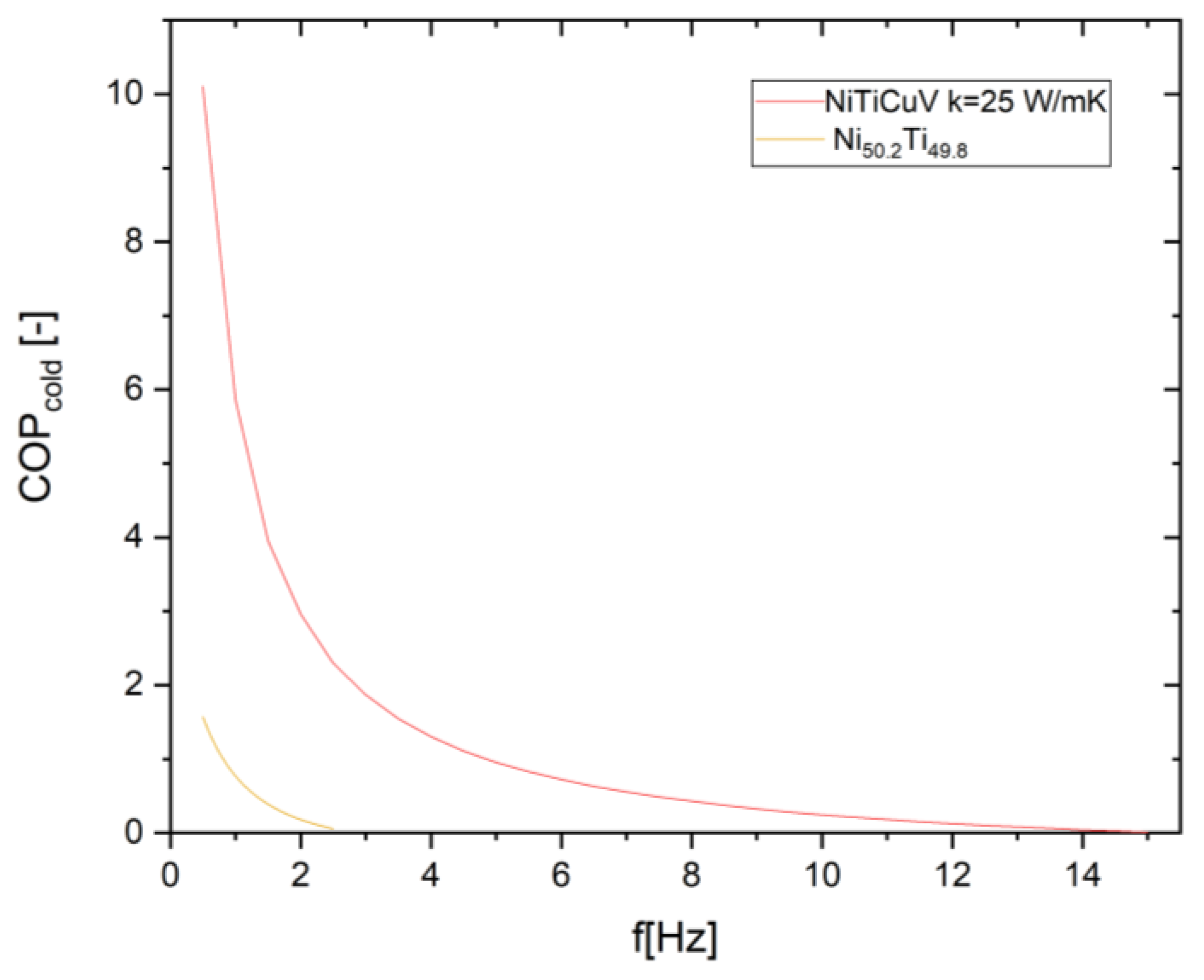
Figure 14.
Temperature jumps on cold side as a function of the cycle frequency of the SSHT system employing NiTiCuV but ITDs with variable thermal conductivity.
Figure 14.
Temperature jumps on cold side as a function of the cycle frequency of the SSHT system employing NiTiCuV but ITDs with variable thermal conductivity.
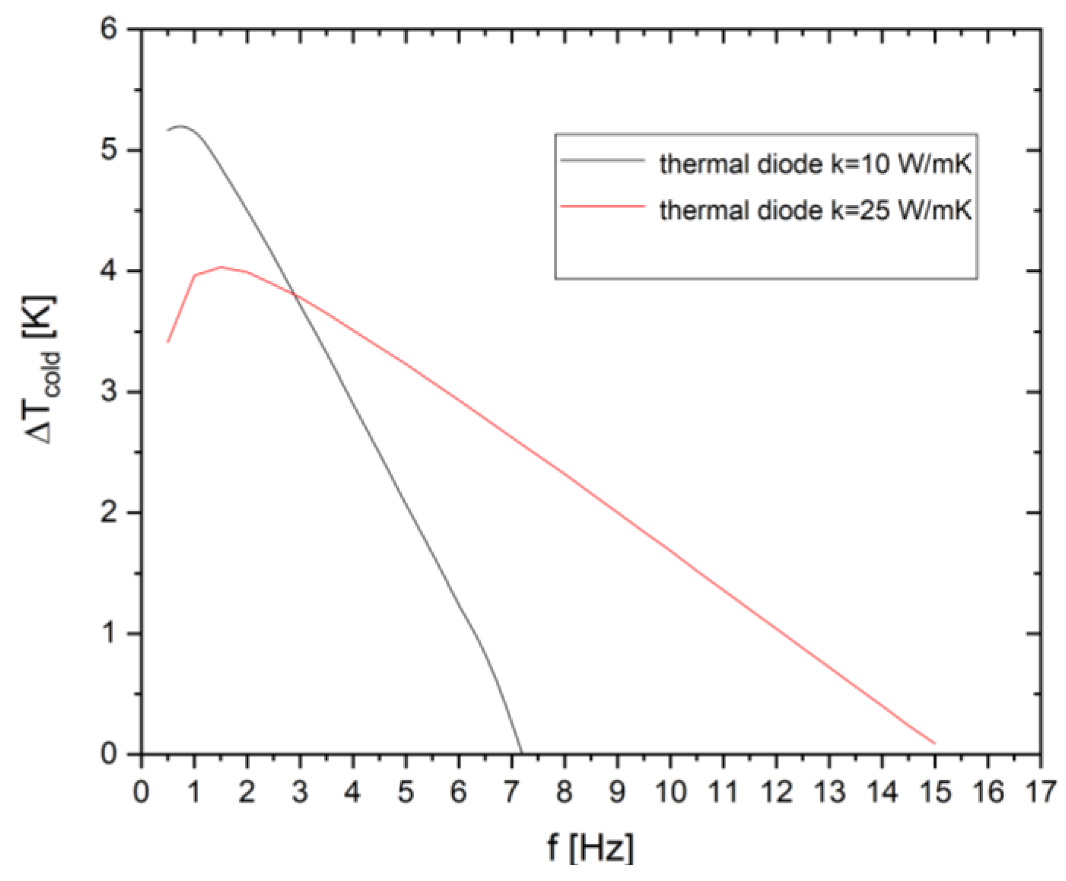
Figure 15.
(a) Cooling power and (b) specific cooling power as a function of the cycle frequency of the SSHT system employing NiTiCuV but ITDs with variable thermal conductivity.
Figure 15.
(a) Cooling power and (b) specific cooling power as a function of the cycle frequency of the SSHT system employing NiTiCuV but ITDs with variable thermal conductivity.
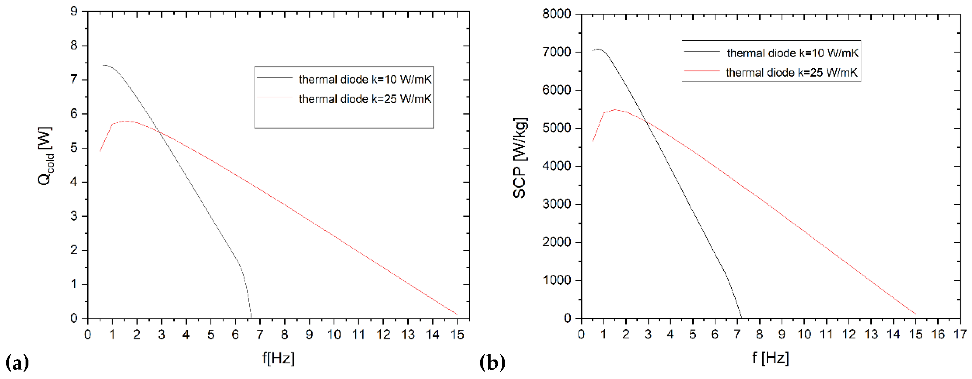
Figure 16.
Coefficient of Performance as a function of the cycle frequency of the SSHT system employing NiTiCuV but ITDs with variable thermal conductivity.
Figure 16.
Coefficient of Performance as a function of the cycle frequency of the SSHT system employing NiTiCuV but ITDs with variable thermal conductivity.
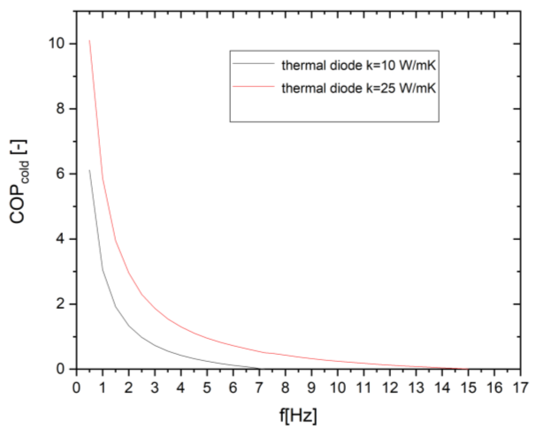
Figure 17.
Temperature jumps on cold side as a function of the cycle frequency of the SSHT system employing NiTiCuV but ITDs with variable thermal conductivity.
Figure 17.
Temperature jumps on cold side as a function of the cycle frequency of the SSHT system employing NiTiCuV but ITDs with variable thermal conductivity.
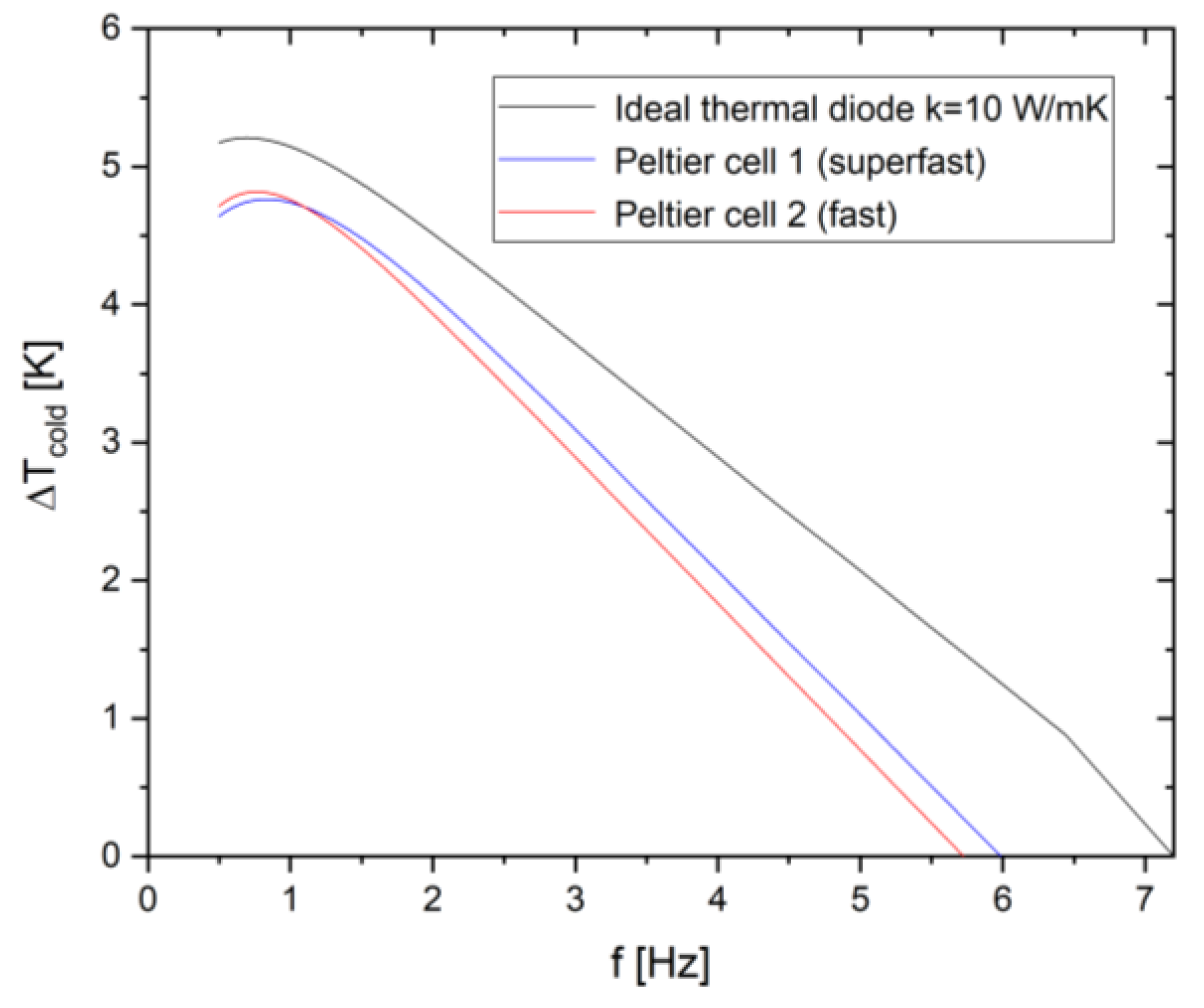
Figure 18.
(a) Cooling power and (b) specific cooling power as a function of the cycle frequency of the SSHT system employing NiTiCuV but ITDs with variable thermal conductivity.
Figure 18.
(a) Cooling power and (b) specific cooling power as a function of the cycle frequency of the SSHT system employing NiTiCuV but ITDs with variable thermal conductivity.
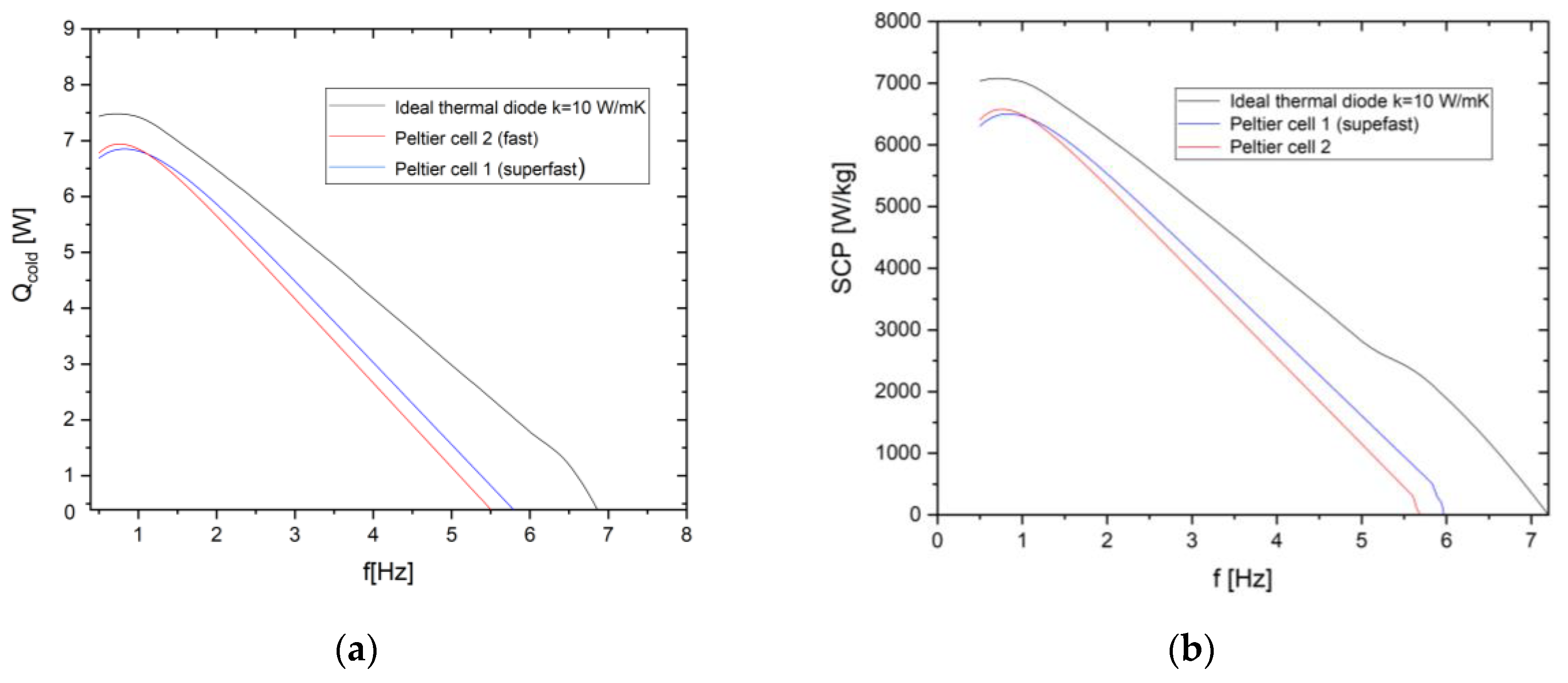
Figure 19.
Coefficient of Performance as a function of the cycle frequency of the SSHT system employing NiTiCuV but ITDs with variable thermal conductivity.
Figure 19.
Coefficient of Performance as a function of the cycle frequency of the SSHT system employing NiTiCuV but ITDs with variable thermal conductivity.
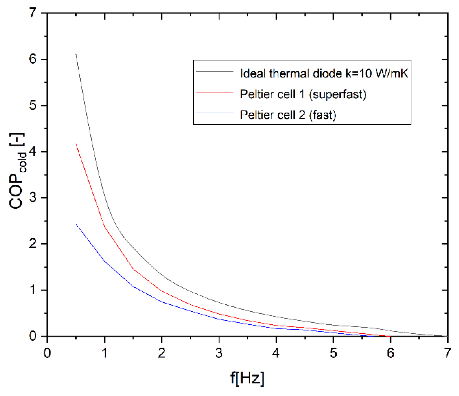

Table 1.
This is a table. Tables should be placed in the main text near to the first time they are cited.
Disclaimer/Publisher’s Note: The statements, opinions and data contained in all publications are solely those of the individual author(s) and contributor(s) and not of MDPI and/or the editor(s). MDPI and/or the editor(s) disclaim responsibility for any injury to people or property resulting from any ideas, methods, instructions or products referred to in the content. |
© 2026 by the authors. Licensee MDPI, Basel, Switzerland. This article is an open access article distributed under the terms and conditions of the Creative Commons Attribution (CC BY) license (http://creativecommons.org/licenses/by/4.0/).
Copyright: This open access article is published under a Creative Commons CC BY 4.0 license, which permit the free download, distribution, and reuse, provided that the author and preprint are cited in any reuse.


