
Submitted:
20 January 2026
Posted:
21 January 2026
You are already at the latest version
Abstract
The object of research in the scientific article is the process of converting wind flow energy into mechanical energy. The process of converting wind energy into mechanical energy is carried out by two counter-rotating wind wheels. And into electrical energy in the generator, with the armature and inductor rotating in opposite directions. The purpose of the scientific article is to study and develop an efficient power supply system for autonomous consumers based on a wind power plant of a special design with an increased wind energy utilization coefficient. In the course of the work, the main parameters of a special-designed wind turbine with counter-rotating wind wheels were determined and the process of electric generation was modeled on the principle of counter-rotation of the armature and generator inductor; a physical model of a special-designed wind turbine based on a two-wheeled system located in the same wind flow and providing rotation of the armature and generator inductor individually from each wind wheel in the opposite direction was developed; a design documentation on the basis of which the experimental design sample was made; experimental studies of the experimental design sample of a wind turbine were conducted to determine its main parameters for the purpose of efficient power supply to autonomous consumers. Main design and technical and economic indicators: optimization of wind power plant parameters, dimensions of wind wheels, their relative location, as well as generator power depending on the expected wind speed. The degree of implementation lies in the fact that a wind generator with variable torque of a wind wheel is patented (patent for invention of the Republicof Kazakhstan No. 36903; Eurasian patent for invention No. 047230). The effectiveness of the research lies in the application of technical solutions patented by the authors in practice, which makes it possible to increase the energy efficiency of wind turbines. Scope of application of the developed wind turbine of special design in the field of alternative energy and decentralized agricultural consumers.
Keywords:
alternative energy
; electric power
; wind turbine
; autonomous power supply
; renewable sources wind power
1. Introduction
1.1. Selection and Justification of the Research Direction
Given the growing consumption of electric energy in the Republic of Kazakhstan in industrial production, it is important to reduce costs in the power supply system [1]. This is relevant for autonomous consumers, who are usually low-powered, and in agriculture [2], electricity consumption can also be seasonal, which leads to high costs.
The use of renewable energy makes it possible to reduce the cost of energy consumed by replacing organic fuel [3,4]. The climatic and natural conditions of the Republic of Kazakhstan provide ample opportunities for using wind energy [5,6].
One of the possible solutions to this issue, possibly by improving the wind turbine of a special design. The principle of rotation of the anchor and inductor parts of the generator from separate counter-rotating wind wheels is proposed, the novelty of which is protected by the patent of the Republic of Kazakhstan No. 36903 (No. 2023/0313. 1. dated 08.11.2024) [7,8].
The main problem of wind turbines is that they operate in a narrow range of wind flow velocity characteristics, namely, from 4-6 m / s to 11-14 m / s [9]. Wind power plants are characterized by the minimum wind speed at which the wind wheel starts to rotate, which is usually 2-3 m / s, and the operating wind speed when the wind generator develops its rated power [10,11].
At wind speeds of more than 14 m / s, in order to avoid damage, it is necessary to limit the speed of rotation of the wind generator blades by ballast resistances or mechanical methods such as changing the angle of attack of the blade or rigid fixation of the blade [12,13], etc.
An analysis of the technical literature and patent development has shown [14,15,16] that there are many developments in the direction of improving wind wheels [17,18], but most of them solving a specific problem [19,20,21], nevertheless have a number of characteristics that do not allow them to be effectively used in low wind conditions [22,23,24], varying from calm to stormy [25,26,27].
A device is known [28], the axis of rotation of the wind wheel coincides with the wind direction, and the planetary drive of the electriccurrent generator of a wind power plant is carried out from a wind turbine consisting of two wind wheels - external and internal, with a common axis and the possibility of counter rotation. The disadvantages are the presence of complex and expensive gear conversion, the need for synchronization of mechanism elements, the need for special equipment for manufacturing a planetary mechanism, losses on gears and reduced efficiency, the need for preventive maintenance of a mechanical transmission, dependence on climatic factors-winter or summer lubrication, etc.
The device under study with counter-rotating wind wheels [7], where a wind generator with an axis of rotation coinciding with the wind direction contains two counter-rotating wind wheels, while one of the wind wheels is attached to the rotor, and the second to the generator stator, the rotor shaft is located inside the hollow outer stator shaft having current-collecting rings, and the outer shaft is attached to to the body of the nacelle through the bearing supports. At the same time, it is possible to increase the production of electric energy with a smaller area of wind wheels, reduce the length of the blade, which will reduce the weight and size, and thereby increase the reliability of the installation. The wind generator will reach its rated generating capacity at lower wind speeds. The wind generator does not require synchronization and is extremely easy to manufacture and maintain.
Integration into existing power supply systems is important for wind farms [29,30,31,32]. There are various types of wind turbine generators [33,34,35]. Various systems and circuit solutions for the introduction of wind power plants into the power supply system of agricultural consumers are also known [36,37,38,39,40,41].
The technical result is a more efficient use of wind energy, the possibility of generating mechanical energy at low wind speeds. However, for the proposed wind turbine, the main parameters are insufficiently studied; it is necessary to develop methods for their determination and optimization, taking into account the incoming wind flow energy and the operating mode of the installation as a whole.
Simulation of the power generation mode based on the principle of counter rotation of the armature and generator inductor. In the course of the study, it is important to establish the influence of wind flow on the operation of wind wheels and their relationship.
To study the relationship between the design and operating parameters of a wind turbine, a simulation of the mode of electric power generation is performed. It is important to jointly study the rotation parameters of wind wheels with the output data of the generator and establish the necessary dependencies to determine the generated electricity of the proposed wind power plant. Insufficient research in this area involves establishing the relationship between the parameters of the wind wheel and generator with the output indicators of the power generation mode.
The results of the study should allow optimizing the parameters of the wind power plant, the size of wind wheels, their relative location, as well as the generator power depending on the expected wind speed. The proposed solutions should make maximum use of the potential energy of the wind flow.
2. Materials and Methods
Today, one of the most common types of wind turbines used on an industrial scale is wind turbines with a horizontal axis of rotation. However, this type of wind turbines has a common disadvantage: weak generation at low wind speeds of up to 4 m / s, and at storm winds above 25 m/s, a low range of operating wind speeds [42,43,44]. Classic wind turbines are not able to operate efficiently in high-speed winds. This is due to the fact that under such conditions there are large forces acting on the wind turbine blades, which can lead to damage and even destruction. Increased load leads to a decrease in the reliability of the system as a whole [45,46,47,48].
In this regard, the task is to increase the efficiency of wind turbines at the specified wind speeds. The paper considers a method for increasing the efficiency of generating electric energy at low wind speeds, by adding a second wind wheel mounted on the stator, rotating in the opposite direction. Based on this, the effect of increasing the relative speed of rotation of the stator and rotor is achieved. The efficiency studies of the presented wind farm of special design were carried out, including experimental studies, and two models of windmills with counter-rotating blades were also developed. These studies are relevant and have potential for further study.
A specially designed wind farm with counter-rotating wind wheels is an efficient technology that allows productive conversion of wind energy into electricity [7]. The principle of operation of such a device and its advantages over traditional wind turbines are considered [37].
Since almost 90% of wind turbines used in the world have a horizontal axis of rotation. Then it is more profitable from a practical and economic point of view to modernize this particular structure. As a result, an experimental model of the wind generator design with counter-rotating blades with a horizontal axis of rotation was constructed [38].
2.1. Development of Design Documentation for a Laboratory Model of a Specially Designed Wind Farm in Accordance with the Requirements of the Unified System of Design Documentation
When developing a laboratory model of a wind turbine of a special design based on a two-wheeled system located in the same wind flow and providing rotation of the armature and generator inductor individually from each wind wheel in the opposite direction, the object of research is a wind generator with counter-rotating blades. A special feature of this design is the presence of two wind wheels that rotate in opposite directions.
Based on the task set in the project, design documentation was developed for a laboratory model of a wind turbine of a special design based on two wind wheels and a rotating inductor and generator armature, the general view of which is shown in Figure 1 (a, b).
The design of the device includes: two wind wheels, one fixed to the stator, the second to the rotor axis, a metal base, a current collector mechanism. During the research, an experimental laboratory model and a semi-industrial installation (experimental sample) were used. Experimental studies have confirmed the theoretical increase in the generation of electrical energy by this design. In practice, a wind generator with counter-rotating blades is used to increase the efficiency of generating electric energy at low wind speeds.
Table 1 shows the developed specification of design documentation for the assembly of a specially designed wind farm.
Based on the results of modeling, a physical model of a wind turbine is developed and created for conducting research in laboratory conditions, which allowed further research and became the basis for creating a prototype.
1.3. Description of the Technological Process of Assembling a Specially Designed Wind Turbine
According to the developed design documents shown in Figure 1, a wind turbine of a special design was assembled.
Assembly procedure for a wind generator with counter-rotating blades:
1. The frame of the wind generator is made of metal profile pipe 20*20*2 (20*20*1,5), according to the drawings.
2. Support bearings are installed on each of the three pillars of the frame, in the center of the upper bar;
3. The base for the future platform for sliding contacts is installed on the central rack, and a dielectric (wooden) surface must be installed on top;
4. Generator;
4.1 A dielectric element "tube with expansion" is attached to the back of the generator, copper contact rings are pressed on this element, for a tighter fit, it is recommended to wind insulating materials under the contact rings;
4.2 The two generator terminals are soldered to the contact rings, having previously passed wires inside the tube that fit snugly to the inner surface of the tube;
4.3 A connecting washer is attached to the opposite side of the generator for attaching blades to it, the main function of the washer is a flat surface on the side of the blade attachment;
4.4 Generator axis lengthened. There are two ways to do this:
1) Remove the existing axle, having previously disassembled the generator and replace it with a solid long hairpin;
2) Using the connecting nuts, extend the existing axle on both sides with a metal stud.
5. Using a template, six blades are cut out of durable plastic materials. Three blades should be at the right angle of attack, three blades at the left. This is achieved by turning the template over before opening it. The length of the blades of the first design is 0.5 m;
6. Cut a circle with a diameter of ~200 mm from sheet metal with a central hole in the center, this disk is necessary for attaching the blades to the rotor;
7. We attach three blades to the cut circle, using self-tapping screws or bolts with nuts;
8. We attach three blades to the generator through a pre-prepared washer;
9. Attach the cut-out circle with blades from the point on the axis;
10. Assemble all the parts together and fix the axle in the bearing units;
11. On the platform of sliding contacts, install two sliding contacts so that they fit snugly to the contact rings when passing a full turn of the generator;
12. Lead wires ~1-1. 5 m long are soldered to the sliding contacts for connecting measuring instruments.
Figure 2 and Figure 3 show the appearance of the created laboratory model and the main elements of a specially designed wind turbine.
The wind generator with counter-rotating wind wheels is an innovative solution that allows you to improve the extraction of wind energy. The principle of operation of this technology is based on the fact that the wind wheels rotate towards each other.
Figure 4 shows a graph of the start-up of wind wheels with a different number of wind wheels involved and combinations of the number of blades.
As can be seen from the graph in Figure 4, there is a relationship between the number of blades involved and the initial speed of rotation of the wind wheel. So, when using three blades on one wind wheel (with the second one blocked), the average starting speed is 1.63 m/s. When using two wind wheels with three blades each, the average starting speed is 1.35 m / s, which is 20% less than when using a single wind wheel. The third type of measurement was performed when three blades were deployed on one of the wind wheels.
When using this technological solution, the average starting speed of the wind wheel is 1.01 m / s, which is more than 30% more than in the second experiment and more than 60% more than in the first. Therefore, we can safely conclude that with the increase in the number of blades and the addition of an additional wind wheel, the required wind speed to start starting the wind wheel decreases.
For primary laboratory studies, a wind generator with counter-rotating wind wheels was used, shown in Figure 2 and Figure 3. This version of the wind generator is achieved by changing the generally accepted design and adding an additional wind wheel that rotates in the opposite direction relative to the first one in the wind direction [7,37,38].
2.4. Investigation of the Main Parameters of a Specially Designed Wind Turbine
When operating a laboratory model of a specially designed wind turbine, three conditionally selected zones of air flow movement are formed that affect the operation of a specially designed wind turbine, which are clearly shown in Figure 5.
To determine the optimal distance between wind wheels, conditions were created on the model under which it was possible to adjust the distance between wind wheels. To maximize the transfer of wind energy, the optimal distance between wind wheels is selected, at which the wind flow stabilizes after the first wind wheel and exerts the maximum impact on the second one [37].
During the operation of a specially designed wind turbine, as shown in Figure 5, three conditionally separated areas of air flow are formed that affect the operation of the wind generator:
1) The air flow zone before interaction with the first wind wheel;
2) The area located between the first and second wind wheels;
3) The area located after the second wind wheel.
Air flow zone before interaction with the first wind wheel. This area does not differ from the area in front of a traditional wind generator.
Figure 6 shows the air flow in zone I.
When the air flow moves on the active screw of the wind wheel, the blades form drag. According to Newton's third law, the force acting on the blades, which is converted into the rotational motion of the propeller, is equal to the force of drag of the blades. These two forces are directed in opposite directions. However, a wind generator with a horizontal axis of rotation (used in scientific research) gets its rotation from the lifting force Fn, which has a direction of 90o, relative to the direction of wind movement [37].
Figure 8 shows the areas where the air flow is located when interacting with wind wheels.
The zone located between the first and second wind wheels has specific properties and features. In this space, there is a twisting of air flows passing through the area of rotation of the first wind wheel. Since wind wheels rotate in opposite directions, the air flow when moving from the first wind wheel to the second, passes a spiral geometry first in one direction, then in the other. Mathematically, you can describe the direction of the air flow with opposite signs. At the moment of changing the direction of movement, swirls occur.
Figure 5 shows a description of the air flow in zoneI, i.e. before interaction with the wind generator. This zone is identical to a traditional wind turbine. The air flow has a linear direction up to the first wind wheel, crossing the first blades, enters zone II (Figure 7).
These swirls negatively affect the conversion of wind energy into electrical energy, since the second wind wheel does not receive an equivalent amount of straight-line air flow in comparison with the first wind wheel.
Swirls of air flows during the operation of an unconventional type of wind generator are shown in Figure 7.
The third zone, located after the second wind wheel, is shown in Figure 8, does not participate in energy generation, since only the energy of the air flow passes there, which is not involved in the generation of electrical energy.
The amount of undeveloped wind energy is determined by the Betz limit [49]. The wind energy utilization rate is 0,593 [50]. That is, of 100% of the wind energy that passes through the windmill area, 59% is used to generate electricity.
Figure 8 shows the air flow of the third zone. Therefore, when calculating power, it is necessary to take into account the fact that the second wheel receives less wind energy than the first one by a factorof k [38].
It should be assumed that this coefficient depends on several parameters:
- wind speed, V, m / s.
- air flow density, P, kg/m3;
- number of blades n, pcs.
- wind wheel rotation speed v, rpm;
- distances between wind wheels l, m.
Based on the above, it is clearly seen that the most convenient parameter for changing the function is the distance between wind wheels.
Obviously, with an increase in the inter-wheel distance, the interaction between the air flows created by the wind wheels will decrease, because when the first wind wheel passes, the air flow will have more time to restore straight properties, which will favorably affect the rotation of the second wind wheel. The straightness of air flows at different inter-wheel distances is shown in Figure 9.
As can be seen from Figure 9, the curvature of the straightness of the air flow decreases as the distance between the first and second wind wheels increases. Since the curvature decreases, the impact on the blades increases and thereby a higher rotation speed is achieved and, accordingly, the generation of electrical energy.
The distance between wind wheels plays an important role in energy production. The results showed that the optimal distance depends on the diameter of the wind wheel and is equal to one radiusr.
3. Results and Discussion
3.1. Experimental Study of the Aerodynamic Characteristics of Wind Wheels with the Determination of the Main Parameters and Indicators
The research paper considers an unconventional design of a wind turbine, so we will consider the effect of sliding blades on the power of a specially designed laboratory model of a wind power plant and the maximum possible indicators of different diameters of wind wheels.
The diameter of the wind wheel is selected based on the power of the installed generator in the wind turbine. For weakly powerful systems, wind wheels with a diameter of several meters are not needed, since a small rotation lever is enough to promote such an electric unit. Wind wheels with large radii are used to power wind turbines of several kW and higher.
Based on the above information, Figure 10 shows graphs of the dependence of wind wheel diameters on the generated capacity.
As can be seen from Figure 10, the more blades on the wind wheel, the smaller the diameter required to generate identical power.
Wind wheels with two and three blades should be considered in more detail, as they have the best balance of aerodynamics and overall weight characteristics.
When the power is increased from 10 to 50 W, the two-bladed wind wheel increases in diameter by 2 times. This relationship is also preserved for a three-bladed wind generator, but the initial blade length of such a unit is longer.
By superimposing the data obtained during experiments with the design of sliding blades on the above data, it is theoretically possible to identify the additional generated power when the mechanism is activated.
Since the laboratory model of a specially designed wind farm was assembled for experiments with a power of ~60 W, it is necessary to increase the scale of data for wind generators with a two-blade wind wheel. It is known that the coefficient of spreading the wind wheels of a wind turbine is 1.2, therefore, it is possible to theoretically make a forecast for increasing generation.
To structure the data with folded and spread blades of the laboratory model, Table 2 was compiled and the following data were obtained.
As can be seen from the calculated data, starting with 30 W of generated energy, a wind generator with spread blades jumps to the next generation stage in comparison with the standard design. So with an initial radius of 3,44 m and 30 W generation, the extended blades increase the radius to 4,13 m, while increasing the potential generation to 40 W. This pattern has a non-linearly increasing character, which allows us to conclude that this design actually theoretically allows increasing the generation of electrical energy.
For a more detailed consideration of this dependence, we construct a graph for a two-bladed wind generator in different positions of the sliding mechanism, shown in Figure 11.
Theoretically, this wind generator design justifies its existence. So to achieve a 3-fold increase in power, it is necessary to increase the diameter of the wind wheel by one and a half.
To consolidate the obtained data, they must be supported by practical modeling. Modeling on an experimental model of a wind farm of a special design was carried out in laboratory conditions, the results obtained are considered and demonstrated in the following sections.
3.2. Instrumentation for Conducting Experiments of the Power Generation Process with Establishing the Relationship of the Studied Parameters
For practical confirmation of the theory, a model of a wind generator with sliding blades was assembled (Figure 2). Experimental studies include two experiments. The first experiment consists in measuring the characteristics of a wind generator with non-spread blades with a screw radius of R1. The second experiment is necessary to measure the characteristics of a wind generator with extended blades and a screw radius of R2.
The characteristics that were taken during the experiments are:
1) Voltage, U (V);
2) Current, I (A);
3) Rotation speed, n (rpm);
Wind speed, Vin (m / s).
When conducting experimental studies, it is necessary to use measuring devices, and it is extremely important to take into account certain factors for each specific application.
Based on the above, the following criteria were used to select a suitable measuring device:
- the desired level of accuracy.
- type of measured value.
- the size and shape of the object being measured.
- the environment in which the measurement will be performed.
In accordance with the above requirements, the following measuring devices were selected.
To measure the voltage at the terminals of the wind generator, a digital voltmeter PZ194U-2X1T120x120 was used. The appearance of the device is shown in Figure 12.
To measure the current, a digital ammeter PA194I120x120 was used, with an accuracy class of 0.2 or 0.5. Figure 13 shows the appearance of the device [51].
The voltmeter has the following technical specifications. The PZ194U single-channel voltmeters are designed to measure voltage and frequency in electrical circuits. Accuracy class 0.2 or 0.5. Four buttons on the front panel for viewing measured values on the indicator and setting up the device (access to the settings menu is password protected). You can also configure it using the iPMS program. iPMS service program for setting up and adjusting instruments, viewing and accumulating measurement results. Setting up the reading range of the device, taking into account the measuring transformer, shunt, and additional resistance applied at its input. Indicator type: 1-line LED indicator (digit height up to 20 mm). Visual overload indication. The degree of protection of panel devices on the front panel is IP66, on the body-IP40. Secure mounting of the panel device with metal brackets. Climatic conditions: operating temperature range--40°C to +70°C; relative humidity - up to 95% at 35°C.
The ammeter has the following technical characteristics, designed to measure strength and frequency in electrical circuits. Accuracy class 0.2 or 0.5. Digital interface: 1RS-485 port (Modbus RTUprotocol). Analog outputs: 1. Four buttons on the front panel for viewing measured values on the indicator and setting up the device (access to the settings menu is password protected). You can also configure it using the iPMS program. iPMS service program for setting up and adjusting instruments, viewing and accumulating measurement results. Setting up the reading range of the device, taking into account the measuring transformer, shunt, and additional resistance applied at its input. Indicator type: 1-line LED indicator (digit height up to 20 mm). The degree of protection of panel devices on the front panel is IP66, on the body-IP40. Secure mounting of the panel device with metal brackets. Climatic conditions: operating temperature range--40°C to +70°C; relative humidity - up to 95% at 35°C.
When measuring the speed of rotation of the wind generator screw, it was performed with a digital tachometer of the AR926 series, shown in Figure 14. An anemometer of the UNI-T UT 363 series was used to measure the velocity and temperature of the air flow during the experimentsUNI-T UT. Figure 15 shows the UNI-T UT363 series anemometer.
The digital tachometer has the following technical characteristics, dand the range of rotation speed measurement: about 2.5 revolutions per minute (oбrpm) to 99999 (rpm). Speed resolution: 0.1 rpm (for a rangeof 2.5rpm to 999.9 oбrpm); 1 oбrpm (for a range of morethan 1000rpm). Measuring distance: about50 mm to 500 mm. Measurement accuracy: ± (0.05% + 1 digit). Sample time: 0.8 seconds (at a rotation speed of morethan 60rpm). Max./Minimum measurement: nis supported. Data storage:nis supported. Clearing memory: nis supported. Range Selection: andvtormaticheskiy. Battery charge indication: nis supported. Power: Poweredby 3 x 1.5 V AAA batteries. Net weight: 91 grams. Size: 150*56*31 millimeters [52,53].
The UNI-T UT363 series anemometer has the following technical characteristics, wind speed range: 0-30 m/s. Division 0.1 m/s. The error is ±(5%+0.5).
Temperature: -10-50°C.The division is 0.1°. The error is ± 2°C.Data commits, podstvetka, auto-shutdown: yes. Size: 160*50*28mm. Battery: 1.5v (AAA) [53].To construct the dependences of the effect of extending blades on the final generation of electric energy, it is necessary:
1) Get data and plot the dependence of the screw rotation speed n, on the wind speed Vin;
2) Obtain data and plot the dependence of the generated voltage U and current I on the speed of rotation of the wind turbine screw n;
3) Compare the obtained dependences of the first and second experiments and identify improvements or deterioration in generation.
3.3. Development of a Model of the Wind Mechanical Part of a Wind Turbine Based on Two Wind Wheels with Details of the Design of the Blade Spreading Mechanism
The mechanism of spreading the blades consists of several key structural parts. All the details of this design can be divided into two main parts, the electrical and mechanical circuit.
The electrical circuit includes such elements as: two servos and sliding contacts.
The mechanical chain includes: two toothed rails, two toothed gears, and a mechanism body.
Structurally, the mechanism is as follows:
1) To set the mechanism in motion, it is equipped with two servos, which are connected to the 220V network via sliding contacts;
2) At the ends of the servo shaft, gear gears are fixed, which transmit rotational motion to the gear rack by rack and pinion transmission;
3) The gear rack receives rotational motion from the gear, converts it into translational;
4) A blade is attached to the gear rack, and at the moment of converting rotational motion into translational motion, the blade extends to a certain distance determined by the design.
In this design, a rack made of polymer materials was used as a gear rack, to facilitate the design. A gear wheel made of polymer materials was also used for the windmill layout, and metal parts can be successfully replaced with polymer ones, since they are currently being made very strong. Figure 16 shows a polymer gear rack equipped with a toothed gear. Figure 17 shows the appearance of the 60DNA-04DB1AKS servomotor.
Model 60 DNA-04 DB 1 AKS drives were used as servos in the blade extension mechanismDNA-04DB1AKS. These drives were used because of their weight and size characteristics and technical characteristics. These servos have magnets on their rotors that induce EMF in the stator windings. Also, it should be noted that these servos have high accuracy. According to the manufacturer's information, the shaft position error is two angular minutes.
These servos are completely closed and have a self-cooling function, which allows you to operate the unit without maintenance for a long time.The blades for the wind turbine are made of strong polymer materials to achieve the angle of attack. The developed and manufactured blades are shown in Figure 18.
For a more complete picture, a drawing of the assembled wind generator has been developed. Figure 19 shows that inside the housing of the "rotor cap", the entire mechanism for spreading the blades is placed.
Based on the developed model of the wind-mechanical part of a wind turbine based on two wind wheels with a detailed design of the mechanism for moving the blades apart, it is necessary to conduct an experimental study.
3.4. Experimental Study of the Characteristics of a Specially Designed Wind Farm with Blades in the Initial State
The first experiment carried out on an experimental setup with the blades not spread apart, shown in Figure 20, implies obtaining characteristics for further comparison with the results of the second experiment.
For the purity of the experiment and to reduce the measurement error, five measurements were made at each wind speed, Table 3 shows the average values, in order to avoid data clutter.
The appearance of the installation during the first experiment is shown in Figure 20.
For further analysis and construction of characteristics, we measure the speed of rotation of the wind generator screw at different wind speeds.
The measurement results are shown in Table 3
Based on the results of measurements of the rotation speed, a characteristic of the dependence of the rotation speed on the wind speed is compiled. Figure 21 shows the characteristic obtained as a result of the experiments.
Based on the graph of dependence shown in Figure 21, it follows that the rotation speed increases relative to the wind speed, almost linearly. Minor deviations from the linear pattern are caused by the error of the instruments and imperfect experimental conditions.
When measuring the speed of rotation, the generated parameters of current (I) and voltage (U) were measured in parallel. The results obtained during the experiments are presented in Table 4.
Based on the data obtained in Table 4, a characteristic of the dependence of the generated current and voltage on the rotation speed is constructed. Figure 22 shows the experimental characteristicsof.
As can be seen from the graphs in Figure 22, at the beginning of measurements, when the wind speed reached 5 m/s (which corresponds to a rotation speed of 230 rpm), the voltmeter shows values in the region of 8 V, with a further increase in speed, the voltmeter continues to grow. As for the generated current, to a greater extent, the current depends on the generated voltage and, according to Ohm's law, has the opposite pattern from the rotation speed. When the generated voltage increases, the current drops.
According to the described result, an increase in voltage generation is expected in the next experiment, since the design with extended blades (increased radius of the wind wheel) predicts a higher rotation speed.
3.5. Experimental Study of the Characteristics of a Specially Designed Wind Farm with Sliding Blades
The second experiment was conducted on the extended-blade setup shown in Figure 23. In theory, the generation of current and voltage should increase, because the shoulder of the applied force increases at the same wind speed.
In this experiment, as well as in the first, five measurements were made for each wind speed. Table 5 shows the mathematically averaged values.
The appearance of the installation on which the second experiment was conducted is shown in Figure 23.
By analogy with the first experiment, we measure the rotation speed at different wind speeds.
Based on the results of measurements of the rotation speed, a characteristic of the dependence of the rotation speed on the wind speed is compiled. Figure 24 shows the characteristic obtained as a result of the experiments.
The results of rotation speed measurements show that at the same wind speed, the rotation speed increased by an average of 20%, which is an indicator that a wind generator with spread blades has a higher rotation speed of the wind wheel under the same wind conditions.
The results of voltage and current measurements are shown in Table 6. Using the data obtained from experiments and recorded in Table 6, a characteristic of the dependence of current and voltage on the rotation speed is constructed (Figure 25).
As a result, the characteristics of the dependence of voltage and current on the rotation speed are plotted, shown in Figure 25.
As can be seen from the graphs in Figure 28, the trend of linear dependence of voltage and current remained from the first experiment, but the generated indicators increased.
A detailed comparison of the results obtained during the experiments is given in the next subsection.
3.6. Comparison of Experimental Characteristics of a Specially Designed Wind Farm
When comparing the characteristics obtained during the experiments in the first and second experiments, a summary table of results 2.7 was constructed.
To graphically display the data obtained in summary Table 2.7, graphs comparing the characteristics of the first and second experiments are constructed. Figure 29 shows rotation speed comparison graphs; Figure 30 shows voltage comparison graphs; and Figure 31 shows current comparison graphs.

Table 2.
7. Summary table of the results obtained during the experiments.
| Wind speed, m/s | First experiment | Second experiment | ||||
| Rotation speed, rpm | Voltage, V | Current, A | Rotation speed, rpm | Voltage, V | Current, A | |
| 5 | 230 | 8,10 | 55,29 | 280 | 10,12 | 69,11 |
| 6 | 260 | 8,74 | 52,14 | 330 | 10,93 | 65,17 |
| 7 | 300 | 9,46 | 47,38 | 370 | 11,82 | 59,22 |
| 8 | 340 | 10,05 | 44,58 | 420 | 12.56 | 55.73 |
| 9 | 410 | 11.01 | 40.71 | 510 | 13.76 | 50.89 |
4. Conclusions
Analysis of the experimental data obtained during the operation of a special wind turbine design shows the following.
Based on the comparative graphs shown in Figure 29, Figure 30 and Figure 31, it should be concluded that the design of a wind generator with sliding blades has a positive effect on the amount of voltage generated.
Figure 29 shows that the speed of rotation of the wind wheel has increased by about 20%, which makes it possible to generate electric energy at a lower wind speed.
Figure 30 shows that the generated voltage increases proportionally as the speed of rotation of the wind turbine blades increases. The corresponding results of the first and second rotational speed measurements are correlated with the voltage measurements.
In Figure 31, the current drop is explained by the generator power. When the generation voltage increases, the current value at the generator terminals decreases, since the rated power of the generator (~0.7 kW) does not exceed the permissible one.
Thus, this design of a specially designed wind farm allows the use of wind energy in areas with lower wind characteristics with constant production. In contrast to increasing the length of the blades, active control systems can dynamically adjust the operating parameters of the wind turbine characteristics, such as the angle of inclination of the blades and the speed of rotation, to maximize the use of current wind conditions.
Under ideal conditions, it can be assumed that the opposite rotation of the stator and rotor will increase the power generated by 2 times. Therefore, the coefficient of added generation due to the second wind wheel has the following value
1 < k < 2.
Since there is a directly proportional relationship between the wind energy absorbed by the second wind wheel and the generated power of the wind generator, it should be assumed that the coefficient of energy generated by a wind generator with counter-rotating wind wheels Pbb relative to a traditional wind generator Pb has the following relationship.
where k is the coefficient of energy generated by a wind generator with counter-rotating wind wheels;
Pbb = k Pb,
Pbb – power of a wind generator with counter-rotating blades;
Pv – the power of a traditional wind generator.
To confirm or refute the theoretical assumption of the value of the coefficient of energy generated by a wind turbine with counter-rotating wind wheels, experimental work was carried out with the created semi-industrial experimental design sample of a wind turbine of special design and an analysis of the obtained values was carried out.
Author Contributions
Conceptualization, S.I.; methodology, S.I. and F.B.; software, D.S. and M.T.; validation, D.K. and G.N.; formal analysis, S.I., F.B. and G.N.; investigation, D.S. and D.K.; resources, S.I. and G.N.; data curation, F.B. and G.N.; writing - original draft preparation, S.I., F.B., G.N. and D.S.; writing—review and editing, S.I.; visualization, S.I., D.K. and M.T.; supervision, S.I.; project administration, S.I., F.B. and G.N.; funding acquisition, D.S., D.K. and M.T. All authors have read and agreed to the published version of the manuscript.
Funding
Participation in the research of the authors S.I., F.B., G.N. was funded of the Science Committee of the Ministry of Science and Higher Education of the Republic of Kazakhstan (Grant No. AP32715297, 2026).
Data Availability Statement
The data presented in this study are available upon request from the corresponding author.
Conflicts of Interest
The authors declare no conflicts of interest.
References
- Petrenko, Y.; Denisov, I.; Koshebayeva, G.; Biryukov, V. Energy Efficiency of Kazakhstan Enterprises: Unexpected Findings. Energies 2020, 13, 1055. [Google Scholar] [CrossRef]
- National Statistics Bureau of the Agency for Strategic Planning and Reforms of the Republic of Kazakhstan. Fuel and energy consumption in households in the Republic of Kazakhstan – - 2022. Available online: https://stat.gov.kz/ru/industries/business-statistics/stat-energy/publications/5188://stat.gov.kz/ru/industries/business-statistics/stat-energy/publications/.
- Osman, A.I.; Chen, L.; Yang, M.; et al. Cost, environmental impact, and resilience of renewable energy under a changing climate: a review. Environ Chem Lett 2023, 21, 741–764. [Google Scholar] [CrossRef]
- Dalei, N.N.; Gupta, A. Adoption of renewable energy to phase down fossil fuel energy consumption and mitigate territorial emissions: evidence from BRICS group countries using panel FGLS and panel GEE models. Discov Sustain 2024, 5, 52. [Google Scholar] [CrossRef]
- Jianzhong, X.; Assenova, A.; Erokhin, V. Renewable Energy and Sustainable Development in a Resource-Abundant Country: Challenges of Wind Power Generation in Kazakhstan. Sustainability 2018, 10, 3315. [Google Scholar] [CrossRef]
- Ministry of Energy of the Republic of Kazakhstan. Available online: https://www.gov.kz/memleket/entities/energo?lang=ru.
- Issenov, S.S. Wind generator with variable torque wind wheel. Patent for invention №36903. Application №2023/0313.1, 2024. [Google Scholar]
- Issenov, S.S. «Wind generator with variable torque of rotation of wind wheel-All Databases» Main identification number: Derwent Primary Accession Number 2025-00938C. Indexed 2025-01-16. (Derwent Innovations Index (Web of Science, Clarivate Analytics). https://www.webofscience.com/wos/alldb/full-record/DIIDW:202500938C («Wind generator with variable torque of rotation of wind wheel». Innovative patent for invention no. KZ36903-B. KZ000313 dated 08.11.2024 Bulletin №2. Ministry of Justice of the Republic of Kazakhstan.
- Spiru, P.; Simona, P.L. Wind energy resource assessment and wind turbine selection analysis for sustainable energy production. Sci Rep 2024, 14, 10708. [Google Scholar] [CrossRef] [PubMed]
- Koshumbaev, M.; Issenov, S.; Iskakov, R.; Bulatbayeva, Y. Development of a vortex wind device. Eastern- European Journal of Enterprise Technologies 2023, 1(8 (121)), 22–29. [Google Scholar] [CrossRef]
- Alam, F.; Jin, Y. The Utilisation of Small Wind Turbines in Built-Up Areas: Prospects and Challenges. Wind 2023, 3, 418–438. [Google Scholar] [CrossRef]
- Qin, S.; Cao, Z.; Wang, F.; Ngu, S.S.; Kho, L.C.; Cai, H. Design of Optimal Pitch Controller for Wind Turbines Based on Back-Propagation Neural Network. Energies 2024, 17, 4076. [Google Scholar] [CrossRef]
- Lu, S.-X.; Shi, H. Technical analysis of pitch angle control for wind turbine. Integr. Circuit Appl. 2023, 40, 70–72. [Google Scholar]
- Moleón Baca, J.A.; Expósito González, A.J.; Gutiérrez Montes, C. Analysis of the Patent of a Protective Cover for Vertical-Axis Wind Turbines (VAWTs): Simulations of Wind Flow. Sustainability 2020, 12, 7818. [Google Scholar] [CrossRef]
- Fukami, K. Pat. No. US9581134B2. Wind turbine blade and manufacturing method thereof. 2013. Available online: https://patents.
- Wang, G.; Petitjean, B. P. A.; Drobietz, R. Pat. No. EP3553307B1. Serrated noise reducer for a wind turbine rotor blade. 2019. Available online: https://patents.google.com/patent/EP3553307B1/en.
- Abdalkarem, A. A. M.; Abdullah, A. F.; Sopian, K.; Haw, L. C.; Muzammil, W. K.; Wong, K. H. The effect of trailing-edge wedge-tails on the aerodynamic characteristics of wind turbine airfoil. IOP Conf. Ser. Mater. Sci. Eng. 2023, 1278(1), 012011. [Google Scholar] [CrossRef]
- Azadani, L.N.; Saleh, M. Effect of blade aspect ratio on the performance of a pair of vertical axis wind turbines. Ocean. Eng. 2022, 265, 112627. [Google Scholar] [CrossRef]
- Foley, A. M.; et al. A critical evaluation of grid stability and codes, energy storage and smart loads in power systems with wind generation. Energy 2020, Т. 205, 117671. [Google Scholar]
- Paraschiv, L.S.; Paraschiv, S. Contribution of renewable energy (hydro, wind, solar and biomass) to decarbonization and transformation of the electricity generation sector for sustainable development. Energy Reports 2023, vol. 9, 535–544. [Google Scholar] [CrossRef]
- Nsafon, B.E.; et al. Optimization and sustainability analysis of PV/wind/diesel hybrid energy system for decentralized energy generation. Energy Strategy Reviews 2020, Т. 32, С. 100570. [Google Scholar] [CrossRef]
- Data from the International Renewable Energy Agency IRENA. Available online: https://www.irena.org/Publications/2024/Mar/Renewable-capacity-statistics-2024://www.irena.org/Publications/2024/Mar/Renewable-capacity-statistics.
- Johnson, K. Doldrums: Siemens’ new wind turbine tackles low-wind areas-Environmental capital-WSJ //Wall Street J. Available:(Accessed– 2009). (accessed on 09 June 2022).
- Tummala, A.; et al. A review on small scale wind turbines //Renewable and sustainable energy reviews; 2016; Volume Т. 56, pp. 1351–1371. [Google Scholar]
- Chioncel, C.P.; Spunei, E.; Tirian, G.-O. The Problem of Power Variations in Wind Turbines Operating under Variable Wind Speeds over Time and the Need for Wind Energy Storage Systems. Energies 2024, 17, 5079. [Google Scholar] [CrossRef]
- Früh, W.G. Assessing the Performance of Small Wind Energy Systems Using Regional Weather Data. Energies Google Scholar] [CrossRef. 2023, 16, 3500. [Google Scholar] [CrossRef]
- Dobrin, E.; Ancuti, M.-C.; Musuroi, S.; Sorandaru, C.; Ancuti, R.; Lazar, M.A. Dynamics of the Wind Power Plants at Small Wind Speeds. In Proceedings of the IEEE 14th International Symposium on Applied Computational Intelligence and Informatics (SACI), Timisoara, Romania, 21–23 May 2020; Google Scholar. [Google Scholar]
- Vashchenko, Yu. F.; Sokolov, G. E. Patent of the Russian Federation 2518783, F03D 7/00; Planetary drive of a wind farm electric current generator. Published on; (RU); Byul. 16, 2014.
- Benzohra, O.; Echcharqaouy, S.S.; Fraija, F.; Saifaoui, D. Integrating wind energy into the power grid: Impact and solutions. In Materials Today: Proceedings; ISSN 2214-7853, 2020; Volume 30, pp. 987–992. Available online: https://www.sciencedirect.com/science/article/pii/S2214785320329850. [CrossRef]
- Oyekale, J.; Petrollese, M.; Tola, V.; Cau, G. Impacts of Renewable Energy Resources on Effectiveness of Grid-Integrated Systems: Succinct Review of Current Challenges and Potential Solution Strategies. Energies 2020, 13, 4856. [Google Scholar] [CrossRef]
- Jonaitis, A.; Gudzius, S.; Morkvenas, A.; Ažubalis, M.; Konstantinaviciute, I.; Baranauskas, A.; Ticka, V. Challenges of integrating wind power plants into the electric power system: Lithuanian case. Renew. Sustain. Energy Rev. Google Scholar] [CrossRef. 2018, 94, 468–475. [Google Scholar] [CrossRef]
- Ahmed, S.D.; Al-Ismail, F.S.M.; Shafiullah; Al-Sulaiman, F.A.; El-Amin, I.M. Grid integration challenges of wind energy: A review. IEEE Access Google Scholar] [CrossRef. 2020, 8, 10857–10878. [Google Scholar] [CrossRef]
- Behabtu, H.A.; Coosemans, T.; Berecibar, M.; Fante, K.A.; Kebede, A.A.; Mierlo, J.V.; Messagie, M. Performance Evaluation of Grid-Connected Wind Turbine Generators. Energies 2021, 14, 6807. [Google Scholar] [CrossRef]
- Koshumbaev, M.; Issenov, S.; Iskakov, R.; Bulatbayeva, Y. Development of a vortex wind device. Eastern- European Journal of Enterprise Technologies 2023, 1(8 (121)), 22–29. [Google Scholar] [CrossRef]
- Zhang, Y.; Ula, S. Comparison and evaluation of three main types of wind turbines. In Proceedings of the 2008 IEEE/PES Transmission and Distribution Conference and Exposition, Chicago, IL, USA, 21–24 April 2008; Google Scholar] [CrossRef; pp. 1–6. [Google Scholar]
- Ren, Y.; Ren, L.; Zhang, K.; Liu, D.; Yao, X.; Li, H. Research on the Operational Strategy of the Hybrid Wind/PV/Small-Hydropower/Facility-Agriculture System Based on a Microgrid. Energies 2022, 15, 2466. [Google Scholar] [CrossRef]
- Issenov, S.; Antipov, P.; Koshumbayev, M.; Issabekov, D. Development of a wind turbine with two multidirectional wind wheels. Eastern-European Journal of Enterprise Technologies 2024, 1(8 (127)), 47–57. [Google Scholar] [CrossRef]
- Antipov, P.; Issenov, S.; Koshumbayev, M.; Auelbek, M.; Nurmaganbetova, G.; Issabekov, D. Regulation of the power of a wind turbine of a special design by changing the length of the blades. Eastern-European Journal of Enterprise Technologies (SCOPUS per.46). 2024, 4(8 (130)), 31 41. [Google Scholar] [CrossRef]
- Martinho, V.J. Energy consumption across European Union farms: Efficiency in terms of farming output and utilized agricultural area. In Energy; Google Scholar, 2016; Volume 103, pp. 543–556. [Google Scholar]
- Calderon, J.; Cureg, J.; Diaz, M.; Guzman, J.; Rudd, C.; Le, H.T. Smart Agriculture: An Off-Grid Renewable Energy System for Farms using Wind Power and Energy Storage. In Proceedings of the 2019 IEEE Power & Energy Society Innovative Smart Grid Technologies Conference (ISGT), Washington, DC, USA, 17–20 February 2019; Google Scholar; pp. 1–5. [Google Scholar]
- Sagyndykova, A.; Khizat, S. Generation of electricity by wind turbines in autonomous working conditions in rural areas. KazATC Bulletin 2023, 126(3), 389–397. [Google Scholar] [CrossRef]
- Wright, A.K.; Wood, D.H. The starting and low wind speed behaviour of a small horizontal axis wind turbine. Journal of Wind Engineering and Industrial Aerodynamics 2004, Volume 92(Issues 14–15), Pages 1265–1279. Available online: https://www.sciencedirect.com/science/article/pii/S0167610504001138. [CrossRef]
- Shiah, Yui-Chuin; Chang, Chia Hsiang; Chen, Yu-Jen; Reddy, Ankam Vinod Kumar. Canard optimization for enhancing the performance of small horizontal axis wind turbine at low wind speeds. Journal of Mechanics 2021, Volume 37, 63–71. [Google Scholar] [CrossRef]
- Umar, D.A.; Yaw, C.T.; Koh, S.P.; Tiong, S.K.; Alkahtani, A.A.; Yusaf, T. Design and Optimization of a Small-Scale Horizontal Axis Wind Turbine Blade for Energy Harvesting at Low Wind Profile Areas. Energies 2022, 15, 3033. [Google Scholar] [CrossRef]
- Zhu, F.; Ding, L.; Huang, B.; Bao, M.; Liu, J. Blade design and optimization of a horizontal axis tidal turbine. Ocean Eng. Google Scholar] [CrossRef. 2020, 195, 106652. [Google Scholar] [CrossRef]
- Alpman, E. Aerodynamic Performance of Small-Scale Horizontal Axis Wind Turbines Under Two Different Extreme Wind Conditions. Journal of Thermal Engineering 2015, 1(3), 420–432. [Google Scholar] [CrossRef]
- Mohammad, Z.; Rasam, A.; Hashemi Tari, P. A Detached-Eddy Simulation Study on Assessing the Impact of Extreme Wind Conditions on Load and Wake Characteristics of a Horizontal-Axis Wind Turbine. Energy 2024, 131438. [Google Scholar] [CrossRef]
- Deeney, Peter; Nagle, Angela J.; Gough, Fergal; Lemmertz, Heloisa; Delaney, Emma L.; McKinley, Jennifer M. End-of-LifeAlternatives for Wind Turbine Blades: Sustainability Indices Based on the UN Sustainable Development Goals. Resources, Conservation and Recycling 2021, 171, 105642. [Google Scholar] [CrossRef]
- Wind Energy Handbook; Burton, Tony, et al., Eds.; John Wiley and Sons; ISBN 0471489972, 2001; p. 65. [Google Scholar]
- Manwell, J. F.; McGowan, J. G.; Rogers, A. L. Wind Energy Explained: Theory, Design and Application, 2nd ed.; Wiley, 2009. [Google Scholar]
- Official website. Available online: https://kip-expert://kip-expert.by/p128037358-pz194u-2x1t-voltmetr.html.
- Official website. Available online: https://racii.kz/cifrovoj-tahometr-ar://racii.kz/cifrovoj-tahometr-ar926-beskontaktnyj-izmeritel-skorosti-vrasheniya.
- Official website. Available online: https://ecounit.kz/p://ecounit.kz/p44382029-uni-ut363-izmeritel.htmlizmeritel.htmlhttps://ecounit.kz/p44382029-uni-ut363-izmeritel.html.
Figure 1.
General view of a laboratory model of a specially designed wind farm (top right).
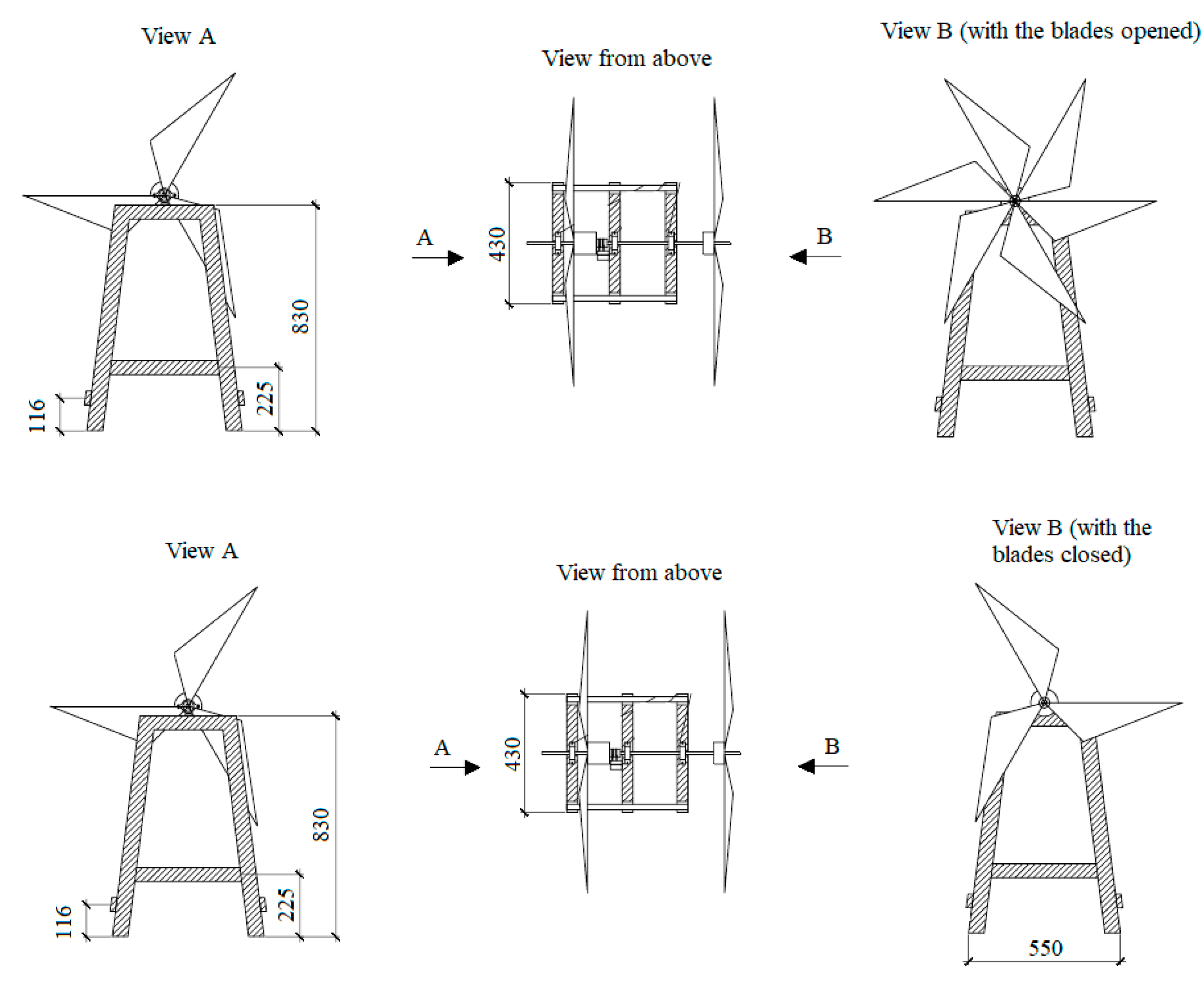
Figure 2.
General view of a laboratory model of a specially designed wind turbine.
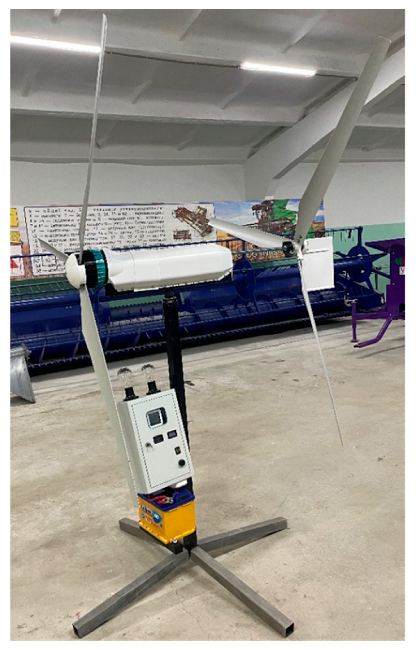
Figure 3.
Main elements of a laboratory model of a specially designed wind turbine.
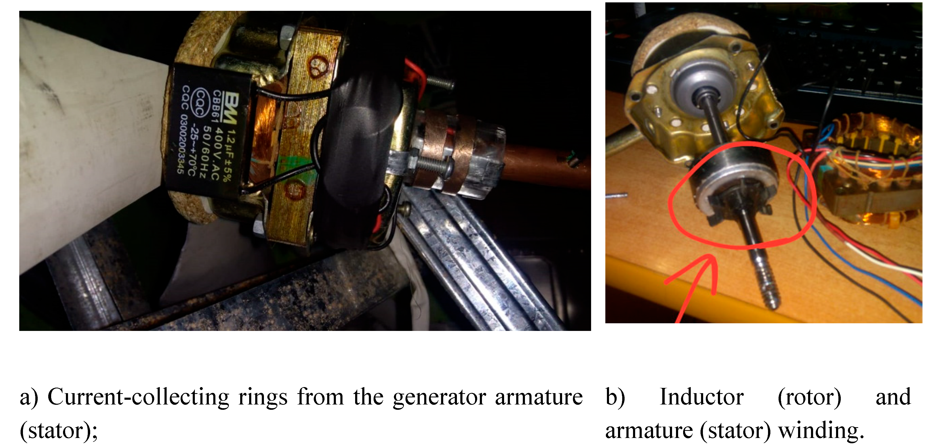
Figure 4.
Dependence of the start of starting the wind wheel on the wind speed.
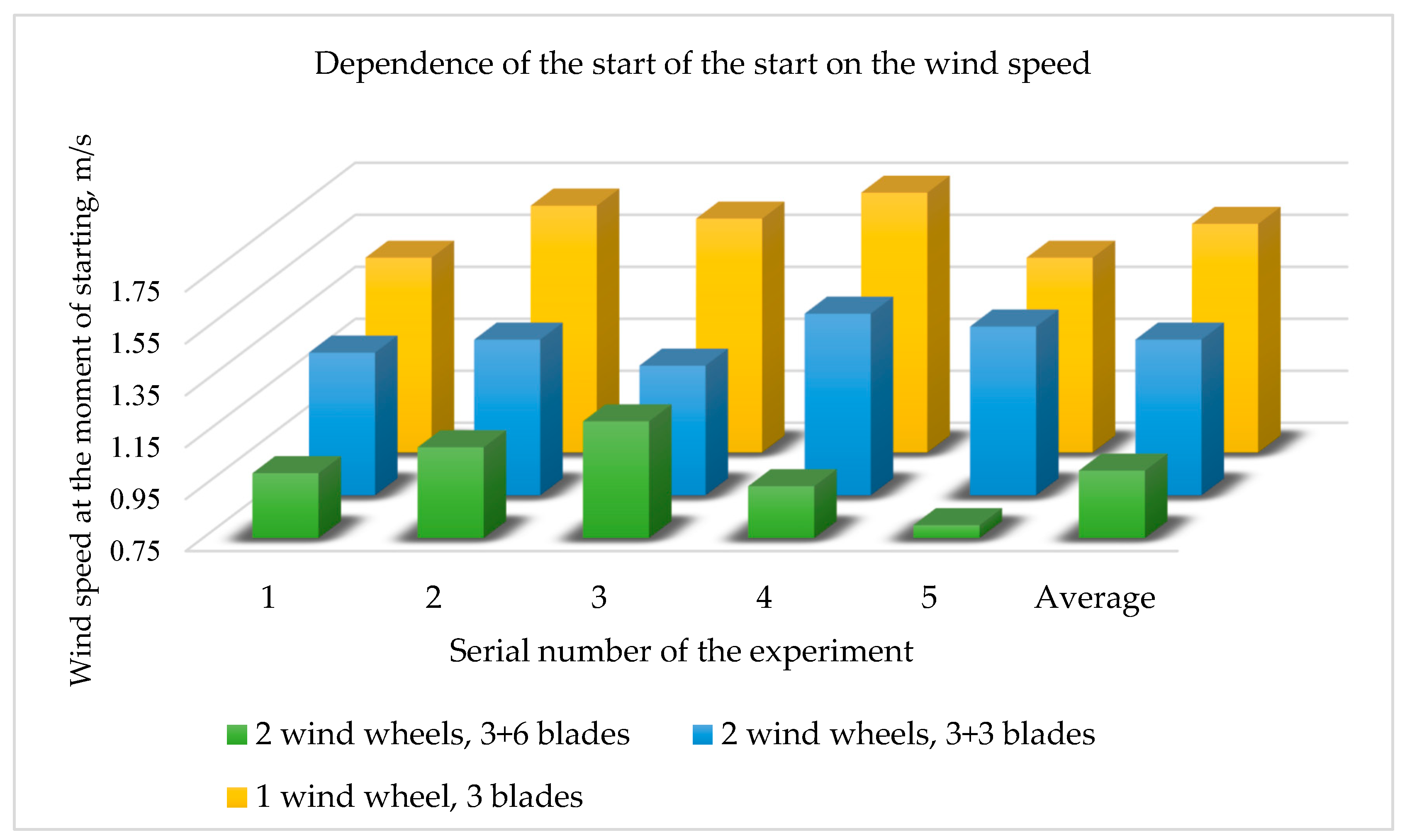
Figure 5.
Zones of the air flow location at interaction with wind wheels.
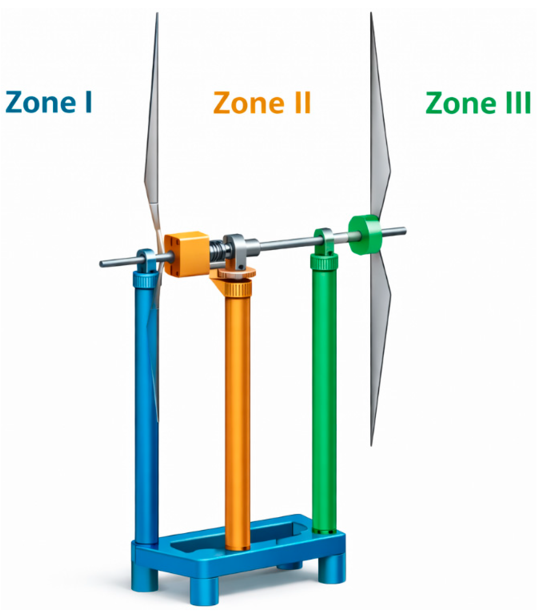
Figure 6.
Air flow direction in zone I.
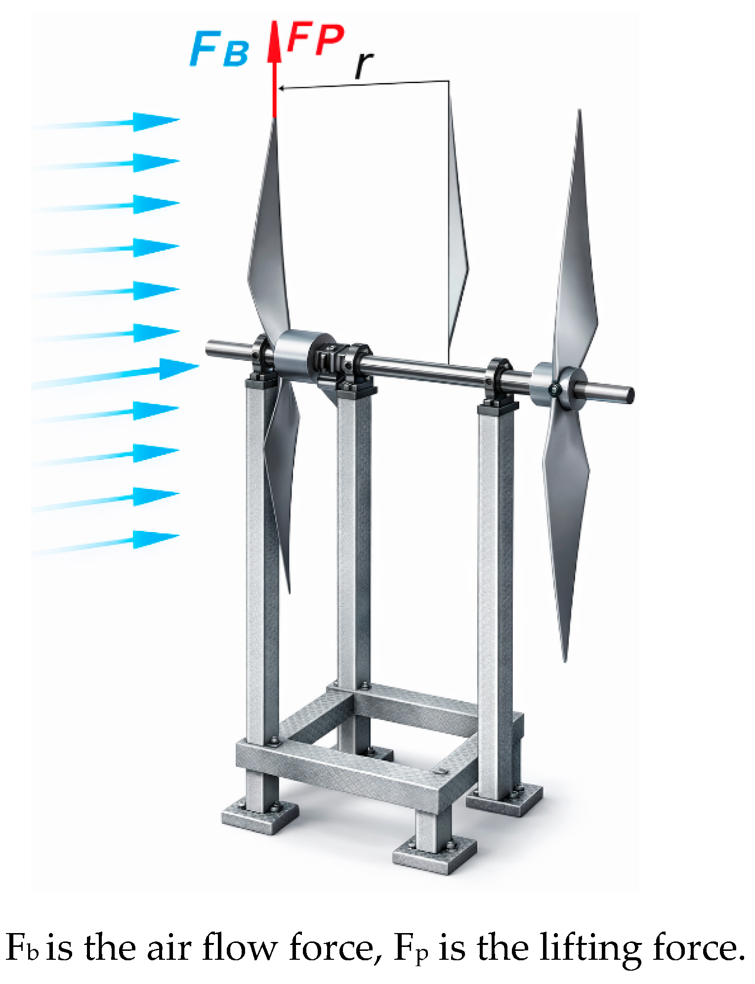
Figure 7.
Air flow direction in zone II.
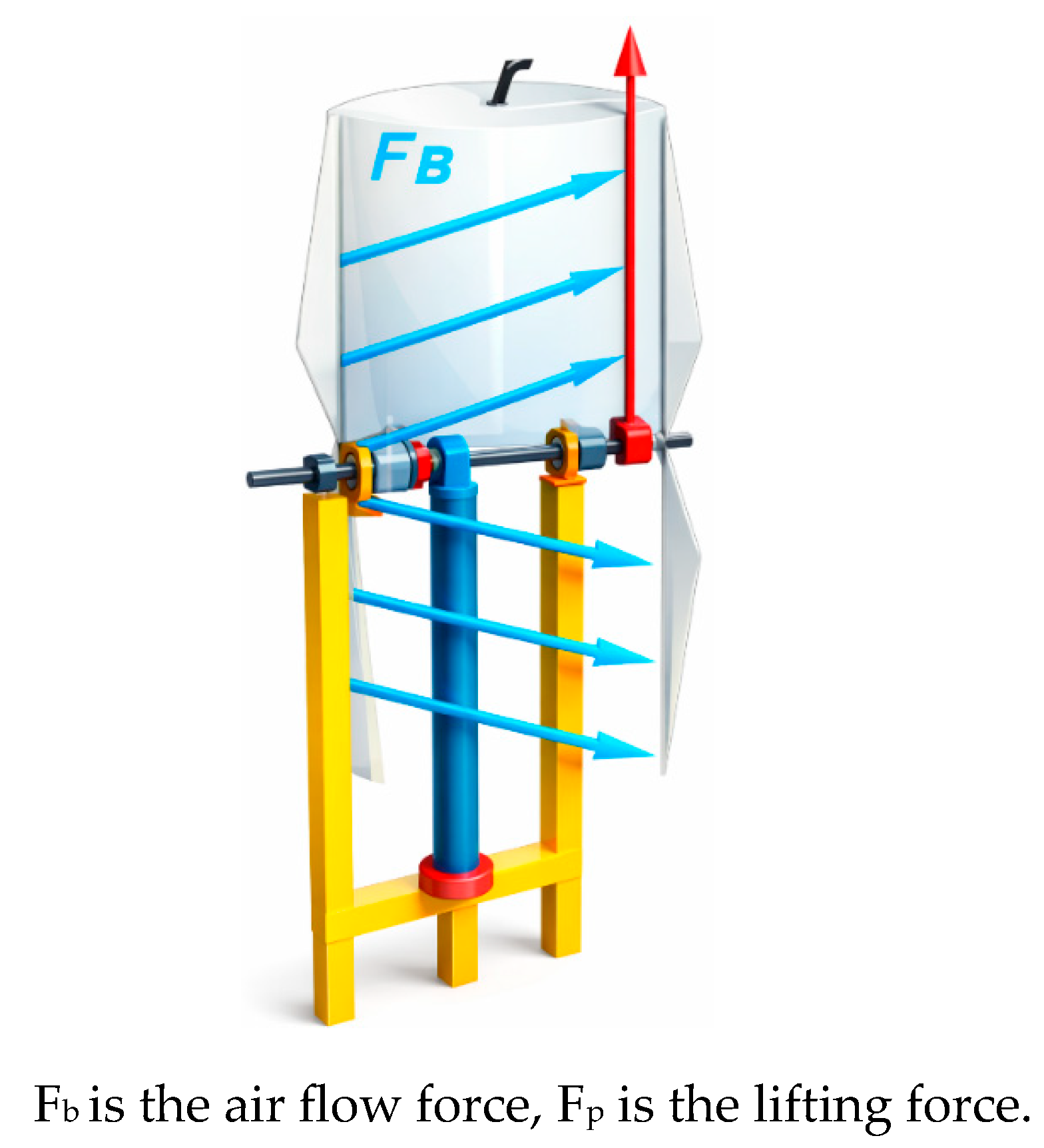
Figure 8.
Zone III air flow.
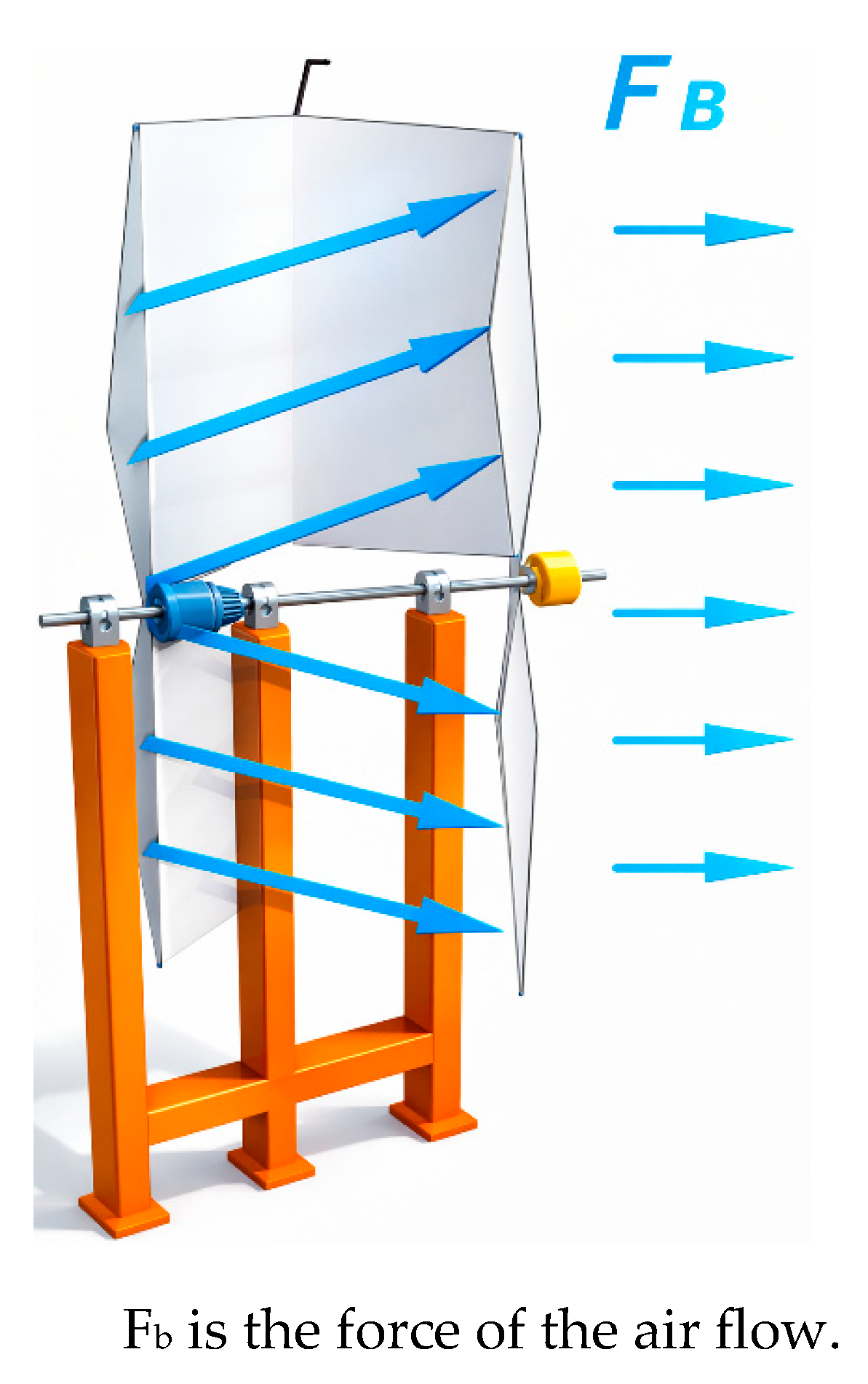
Figure 9.
Straightness of air flows at various temperatures inter-wheel distances.
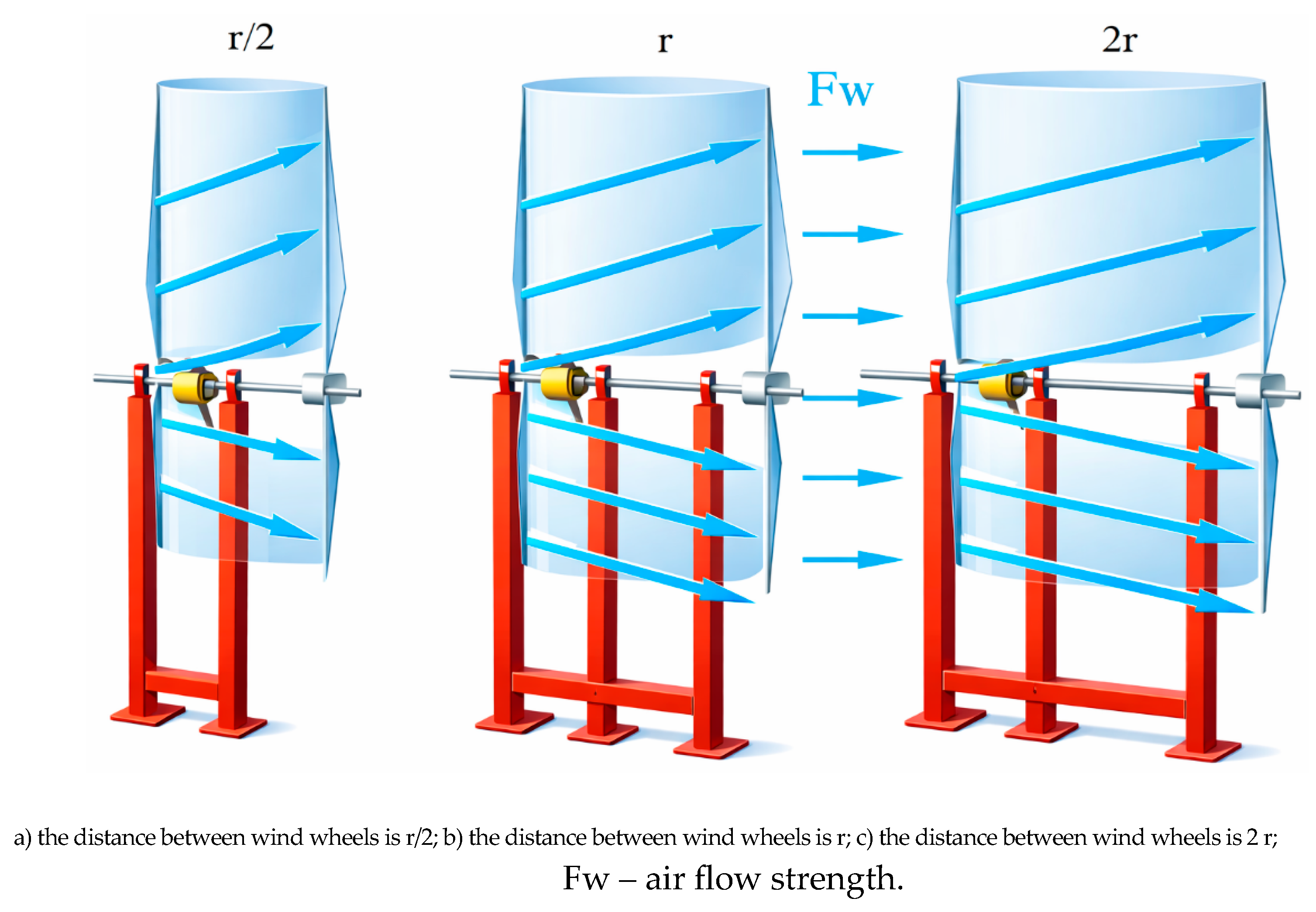
Figure 10.
Graphs of the dependence of wind wheel diameters on the maximum power generated by the wind generator.
Figure 10.
Graphs of the dependence of wind wheel diameters on the maximum power generated by the wind generator.
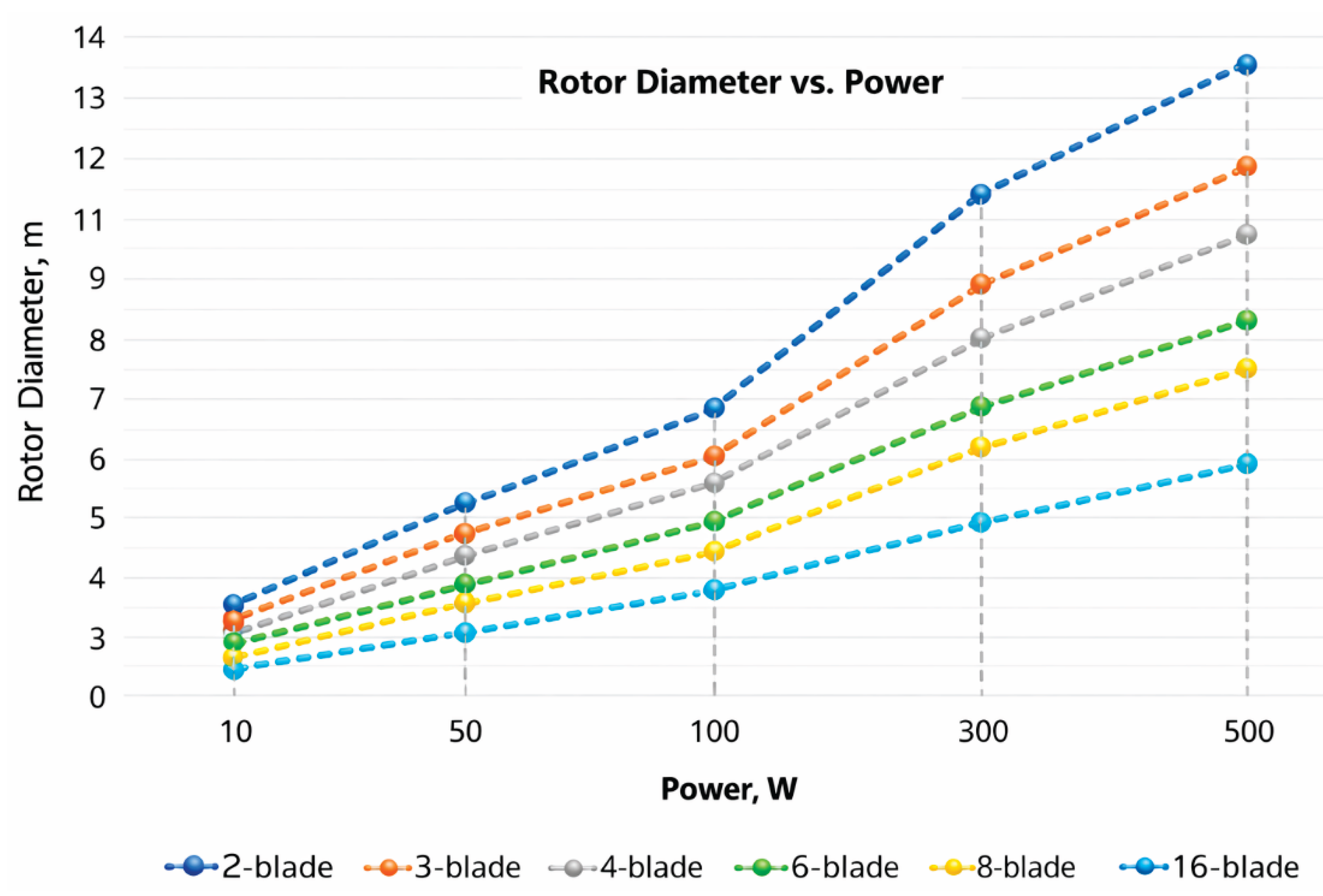
Figure 11.
Power dependence of a two-bladed wind generator in the range of 10-60 W depending on the diameter of the wind wheel.
Figure 11.
Power dependence of a two-bladed wind generator in the range of 10-60 W depending on the diameter of the wind wheel.
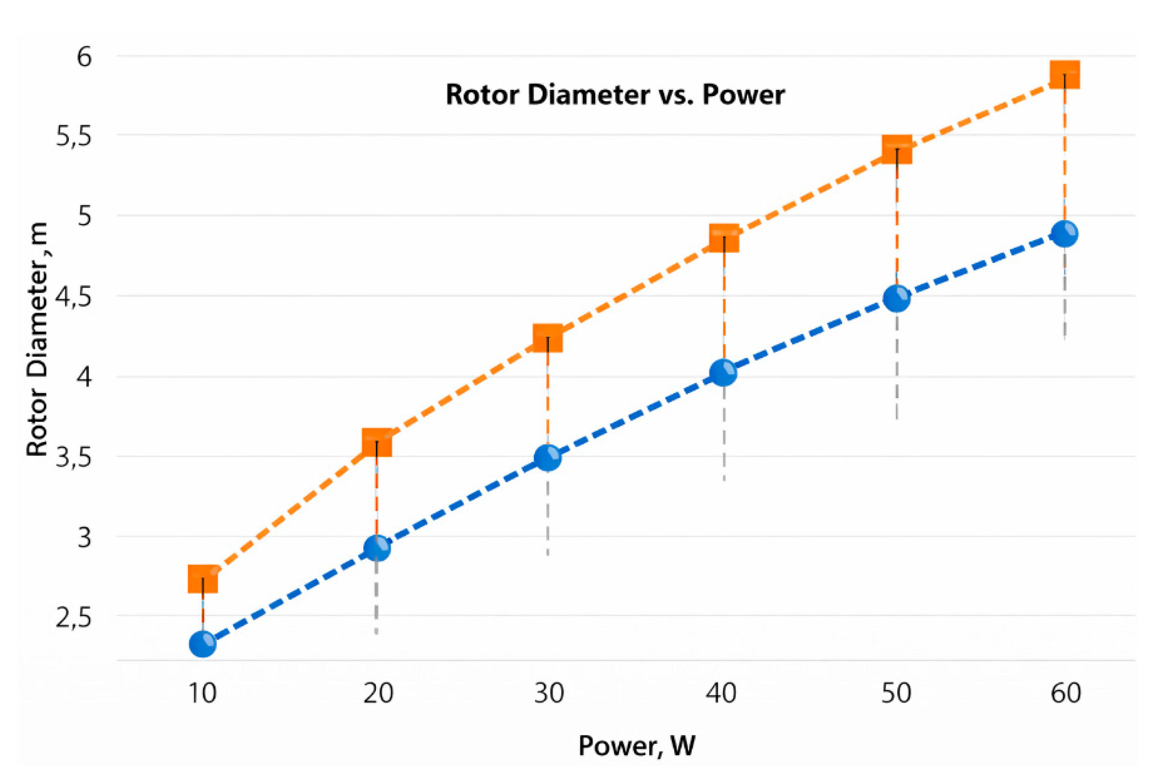
Figure 12.
Appearance of a digital grade voltmeter PZ194U-2X1T120х120.
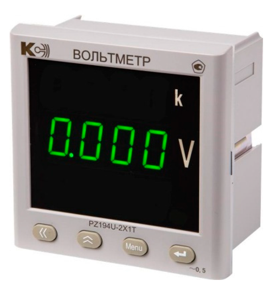
Figure 13.
Appearance of the digital ammeter PA194I120x120.

Figure 14.
Digital tachometer AR926 in the process of measuring parameters.
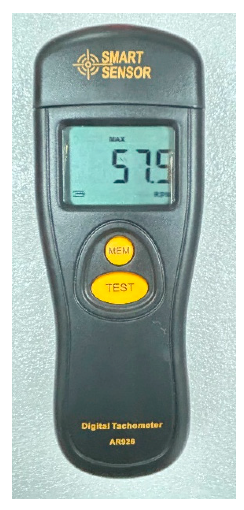
Figure 15.
Anemometer of the UNI-T UT363 series.
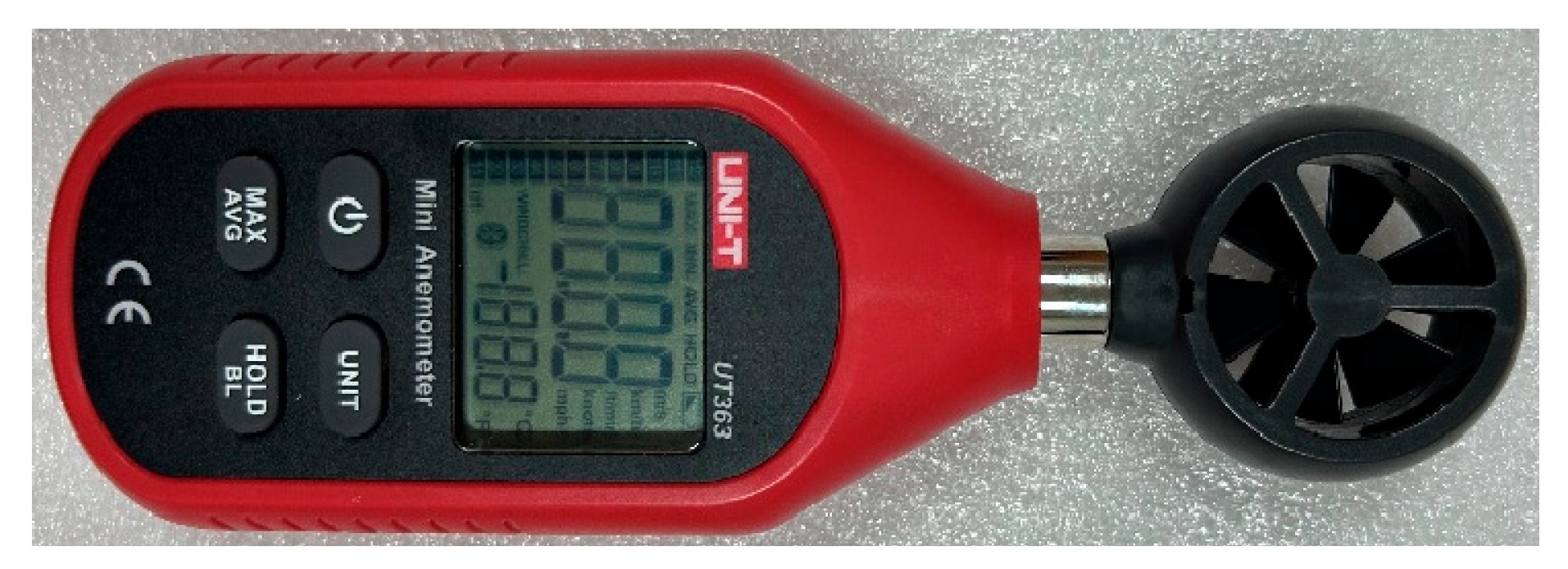
Figure 16.
Polymer gear rack with pinion.
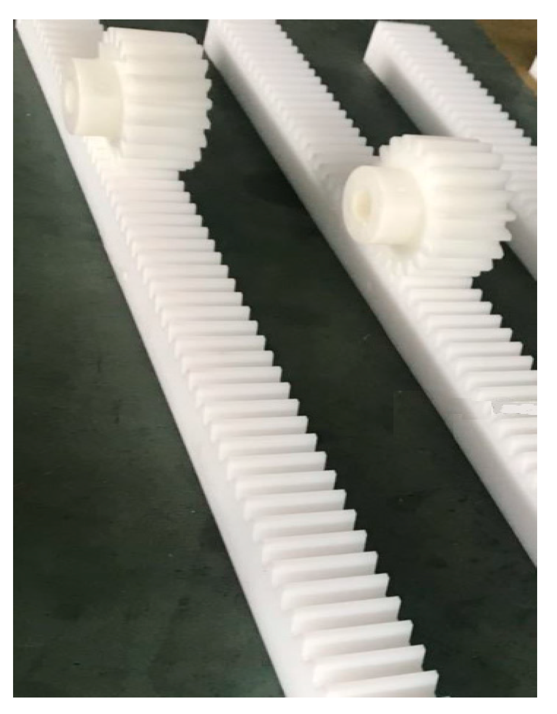
Figure 17.
Servo motor60DNA-04DB1AKS.
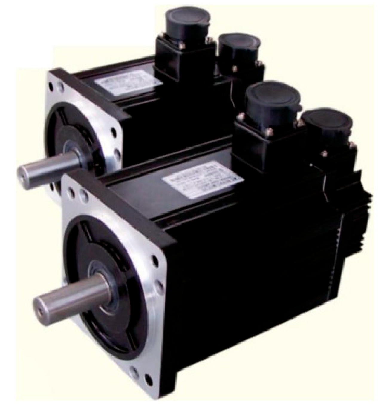
Figure 18.
Manufactured wind turbine blades.
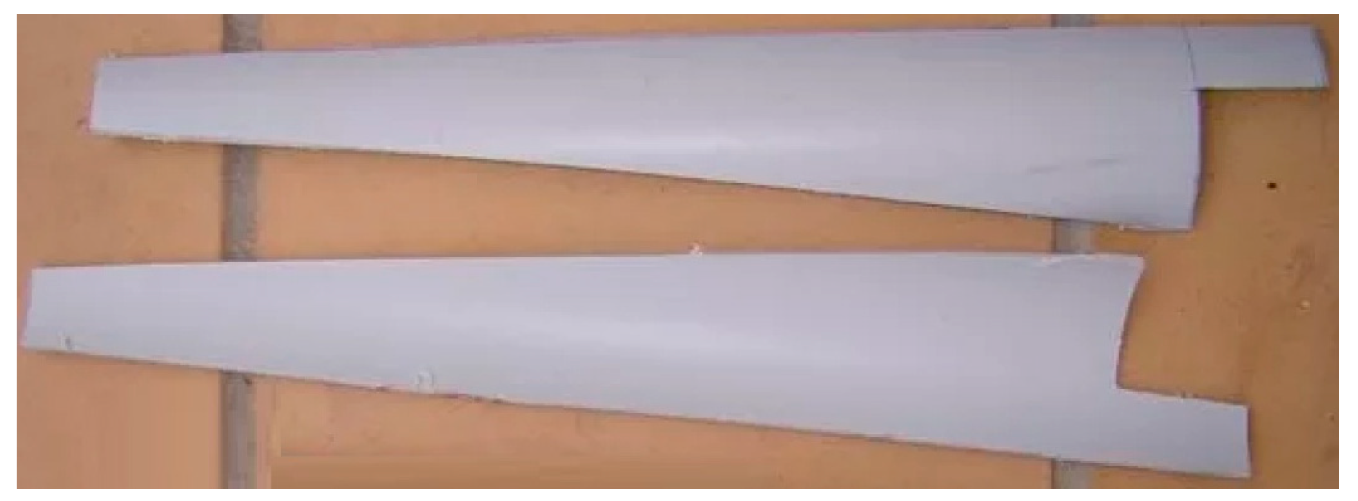
Figure 19.
Drawing of a wind generator with a blade extension mechanism.
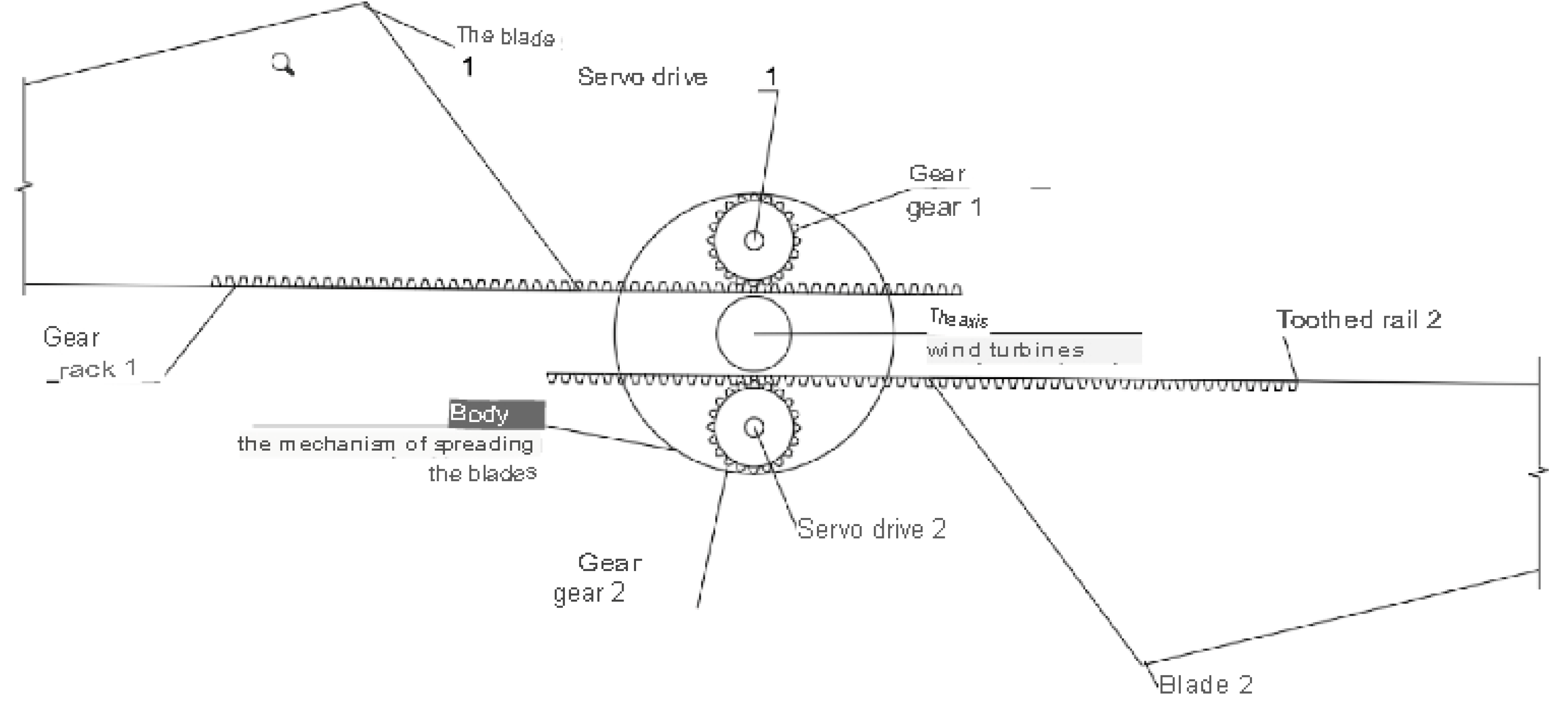
Figure 20.
A specially designed wind farm with a blade extension mechanism, blades in the initial state.
Figure 20.
A specially designed wind farm with a blade extension mechanism, blades in the initial state.
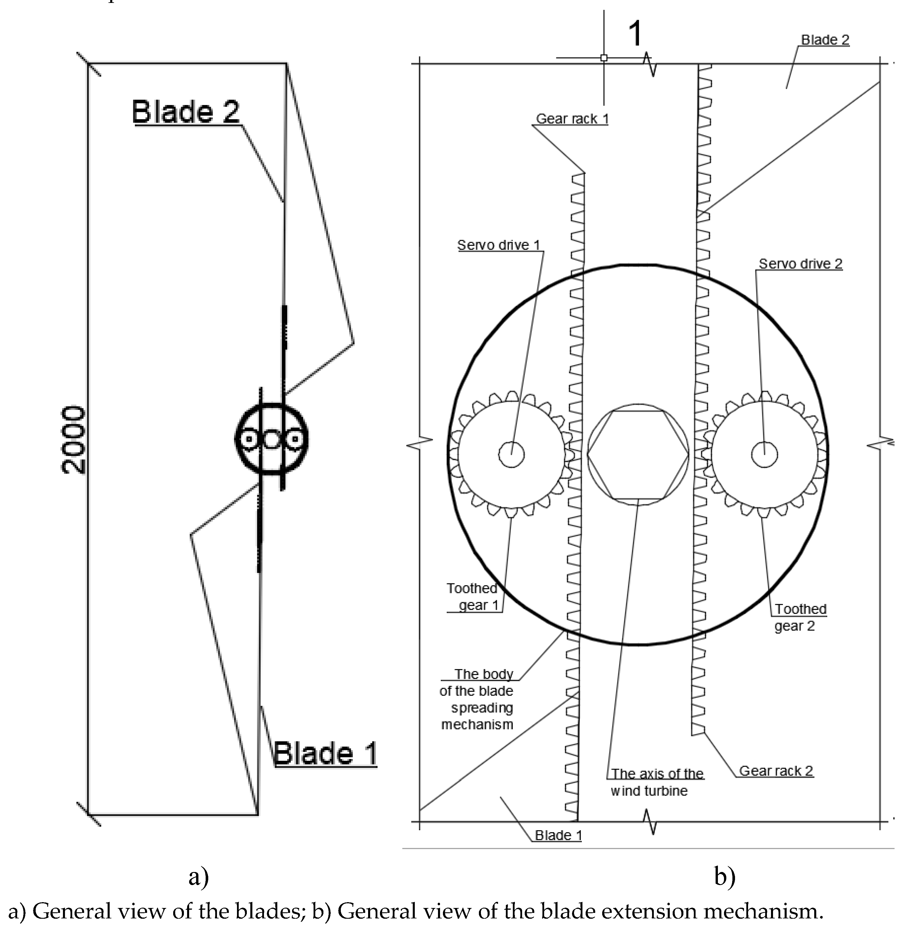
Figure 21.
Obtained characteristic of the rotation speed dependence from the wind speed.
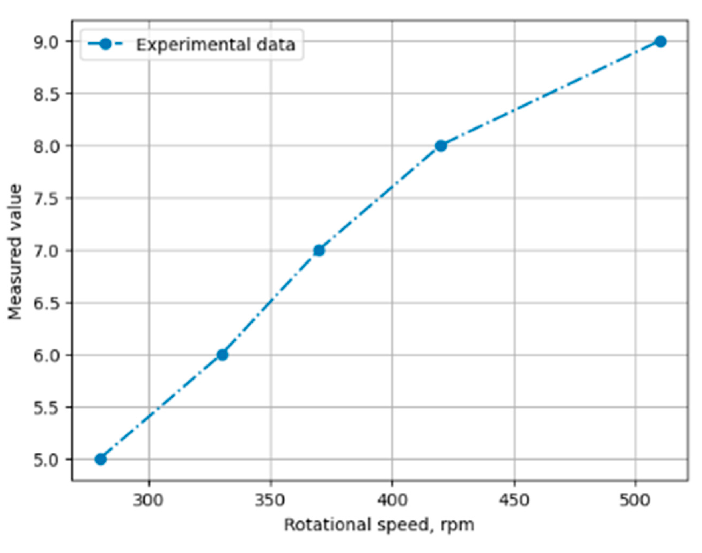
Figure 22.
Obtained characteristics of the voltage-current relationship depending on the speed of rotation (blue - U, orange-I).
Figure 22.
Obtained characteristics of the voltage-current relationship depending on the speed of rotation (blue - U, orange-I).
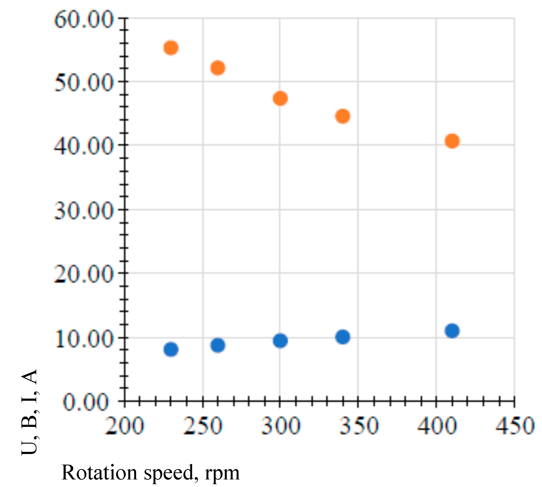
Figure 23.
A specially designed wind farm with a blade extension mechanism, the blades in the extended state.
Figure 23.
A specially designed wind farm with a blade extension mechanism, the blades in the extended state.
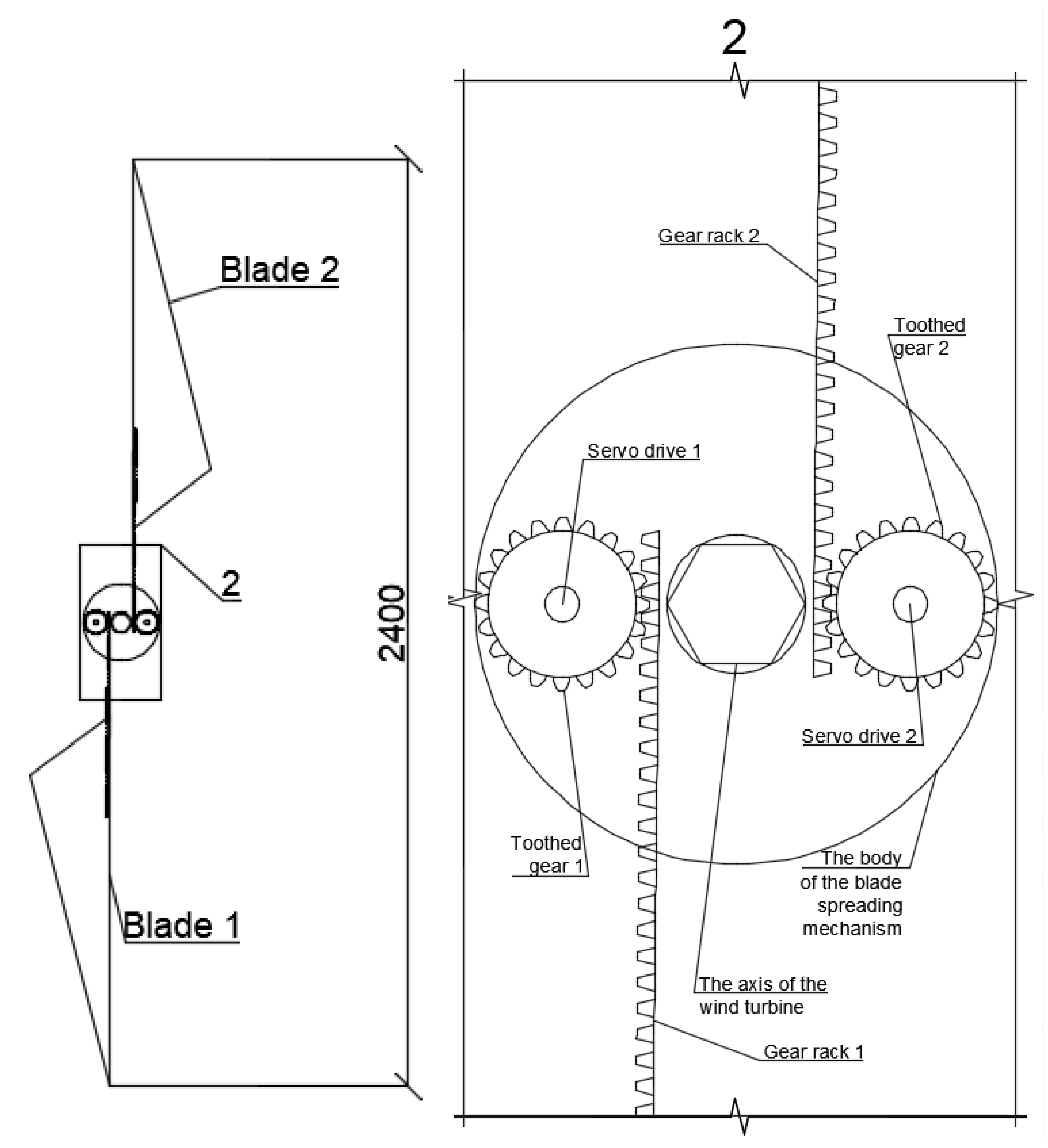
Figure 24.
Characteristic of the dependence of the rotation speed on the wind speed.
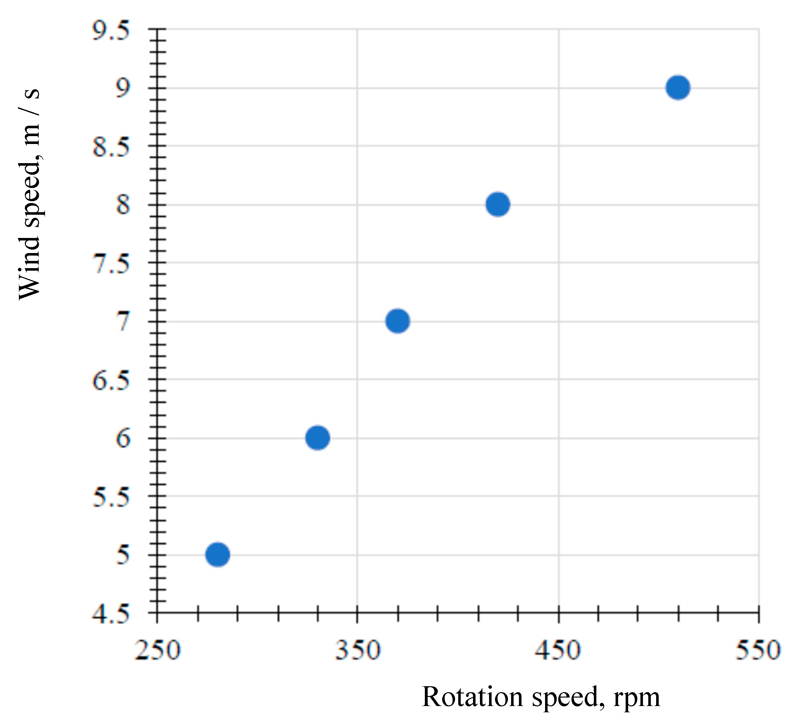
Figure 25.
Voltage and current dependence characteristics depending on the speed of rotation (blue - U, orange - I).
Figure 25.
Voltage and current dependence characteristics depending on the speed of rotation (blue - U, orange - I).
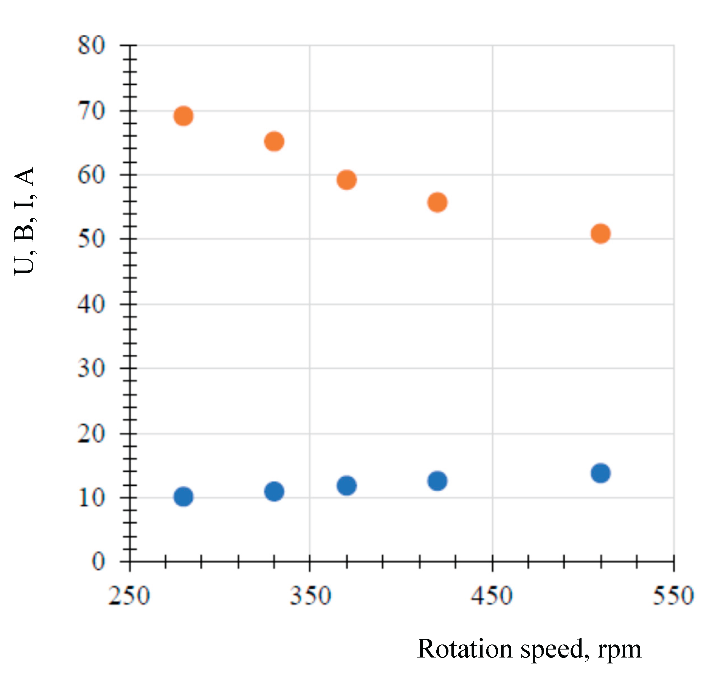
Figure 29.
Comparative graphs of the rotation speed of two experiments (blue color indicates speed 1, orange color indicates speed 2).
Figure 29.
Comparative graphs of the rotation speed of two experiments (blue color indicates speed 1, orange color indicates speed 2).
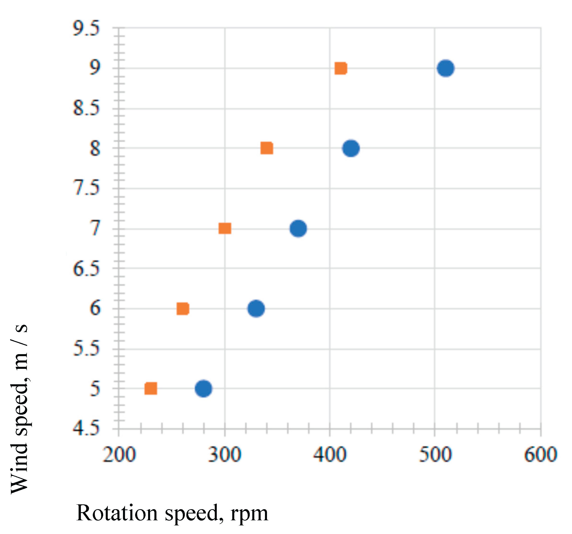
Figure 30.
Comparative voltage graphs of two experiments (in blue - velocity 1, in orange-velocity 2).
Figure 30.
Comparative voltage graphs of two experiments (in blue - velocity 1, in orange-velocity 2).
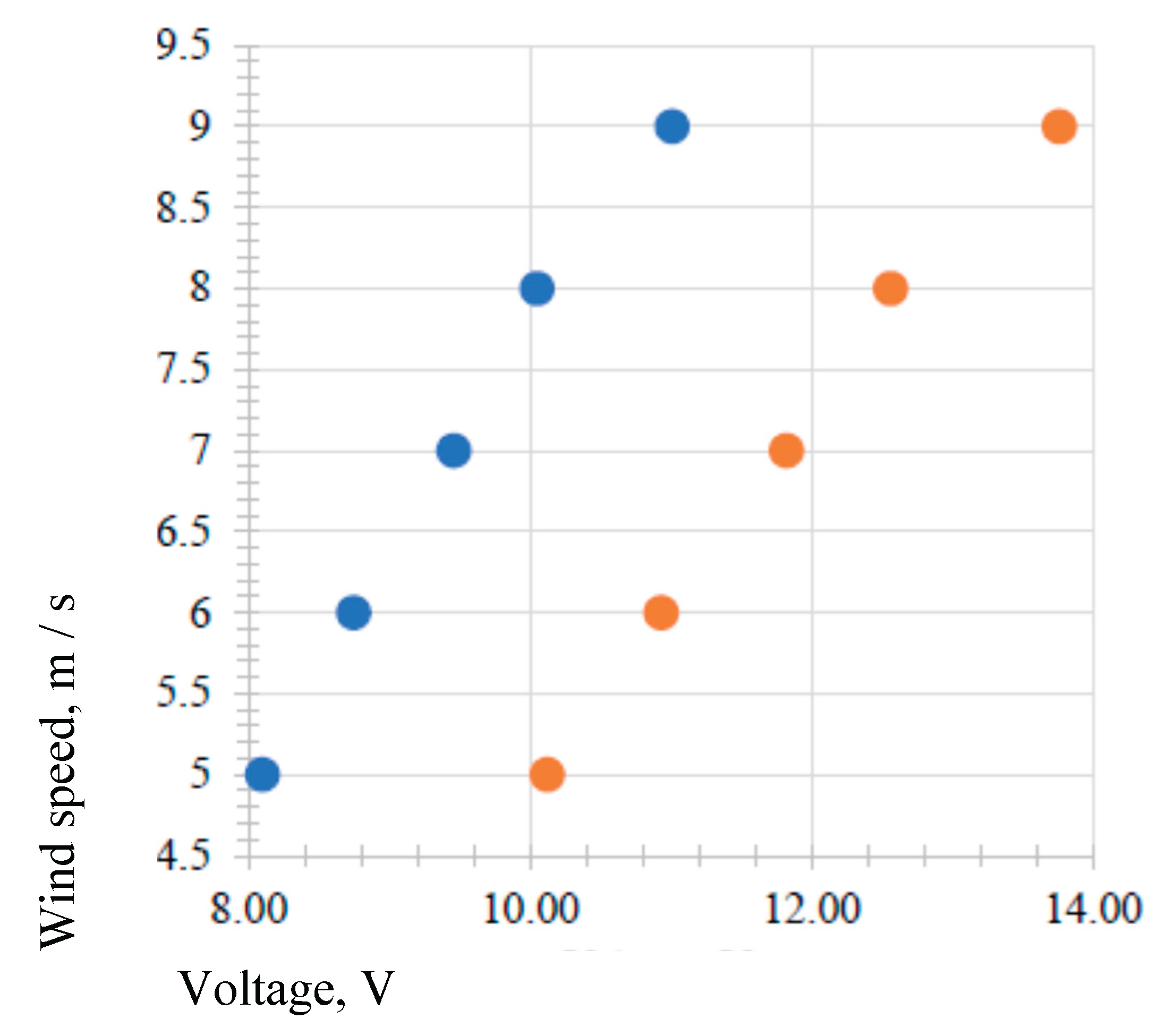
Figure 31.
Comparative current plots of two experiments (blue U1- U1, orangeU-U2, gray - U Uaverage).
Figure 31.
Comparative current plots of two experiments (blue U1- U1, orangeU-U2, gray - U Uaverage).
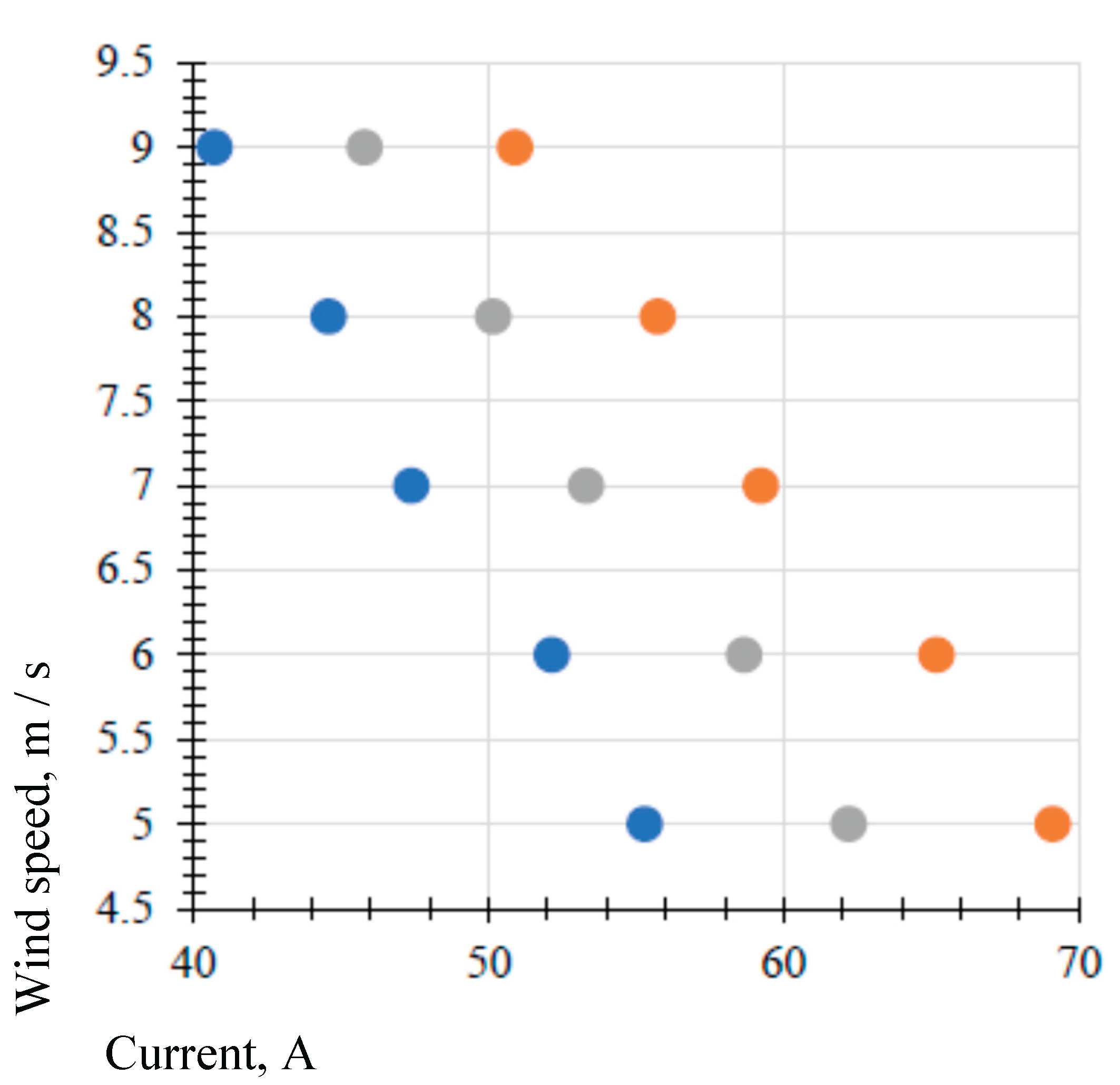
Table 1.
Specification for design documentation.
| Pos. | Name | Qty | Weight units kg |
| . 1 | Frame assembled from a metal profile 20*20*2 (1,5) | 1 | |
| 2 | Blades 1, with the possibility of unfolding from 3, to 6 units, rotate the axis of the wind generator | 1-0 | , 1 |
| 3 | Blades 2, without the possibility of unfolding, 3 units, rotate the stator of the wind generator, are attached to generator housing | 1 | |
| 4 | Wind generator stator | 1-5 | - |
| 5 | Sliding contact block | 1 | |
| 5.1 | -2 contact rings | ||
| 5.2 | - 2 sliding contacts | ||
| 5.3 | -platform for installing sliding contacts | ||
| 6 | Axis of the wind generator, made of M10 bushing | 1 | |
| 7 | Bearing supports, fix the axis of the wind generator, with the possibility of rotation | 3 | |
| 8 | Jumper, made of a metal profile 40x20 | 2 | |
| 9 | Blade folding unit | 1 |
Table 2.
Comparison of theoretical results of operation of the blade spreading mechanism.
| № | Power, W | Wind generator with closed blades | Wind generator with extended blades |
| 1 | 10 | 2 | 2,4 |
| 2 | 20 | 2,82 | 3,38 |
| 3 | 30 | 3,44 | 4,13 |
| 4 | 40 | 4 | 4,8 |
| 5 | 50 | 4,48 | 5,38 |
| 6 | 60 | 4,9 | 5,88 |
Table 3.
Results of rotation speed measurements.
| № | Wind speed Vv, m / s | Rotation speed n, rpm |
| 1 | 5 | 230 |
| 2 | 6 | 260 |
| 3 | 7 | 300 |
| 4 | 8 | 340 |
| 5 | 9 | 410 |
Table 4.
Results of measurements of the generated parameters of the current (I) and voltage (U) of the blade in the initial state at the measured rotation speed (n).
Table 4.
Results of measurements of the generated parameters of the current (I) and voltage (U) of the blade in the initial state at the measured rotation speed (n).
| № | Rotation speed n, [rpm] | Voltage U, V | Current I, A |
| 1 | 230 | 8,10 | 55,29 |
| 2 | 260 | 8,74 | 52,14 |
| 3 | 300 | 9,46 | 47,38 |
| 4 | 340 | 10,05 | 44,58 |
| 5 | 410 | 11,01 | 40,71 |
Table 5.
Results of rotation speed measurements.
| № | Wind speed Vv, [m/s] | Rotation speed n, [rpm] |
| 1 | 5 | 280 |
| 2 | 6 | 330 |
| 3 | 7 | 370 |
| 4 | 8 | 420 |
| 5 | 9 | 510 |
Table 6.
Results of measurements of the generated current and voltage with the blades spread apart, at the measured speed of rotation.
Table 6.
Results of measurements of the generated current and voltage with the blades spread apart, at the measured speed of rotation.
| № | Rotation speed n, [rpm] | Voltage U, V | Current I, A |
| 1 | 280 | 10,12 | 69,11 |
| 2 | 330 | 10,93 | 65,17 |
| 3 | 370 | 11,82 | 59,22 |
| 4 | 420 | 12,56 | 55,73 |
| 5 | 510 | 13,76 | 50,89 |
Disclaimer/Publisher’s Note: The statements, opinions and data contained in all publications are solely those of the individual author(s) and contributor(s) and not of MDPI and/or the editor(s). MDPI and/or the editor(s) disclaim responsibility for any injury to people or property resulting from any ideas, methods, instructions or products referred to in the content. |
© 2026 by the authors. Licensee MDPI, Basel, Switzerland. This article is an open access article distributed under the terms and conditions of the Creative Commons Attribution (CC BY) license (http://creativecommons.org/licenses/by/4.0/).
Copyright: This open access article is published under a Creative Commons CC BY 4.0 license, which permit the free download, distribution, and reuse, provided that the author and preprint are cited in any reuse.


