
Submitted:
16 January 2026
Posted:
20 January 2026
You are already at the latest version
Abstract
Façade integrated solar cooling technologies enable the utilisation of façade surface potential and the provision of resilient cooling. This work compares three solar cooling scenarios, positioning a solar cooling element in the west and east façades. The 2ACE scenario is based on a compact adsorption cooling concept, while the 2PV scenario directly drives a compression chiller with photovoltaic elements, and 2PVB incorporates an additional battery. All Modelica system models are implemented in Modelon Impact and operated using dynamic optimisation for the hottest day of the year. Results indicate that the 2ACE scenario, utilising the adsorbent Silica Gel SG123, achieves near to double the self-sufficiency compared to Zeolite 13X. No clear optimal area balance between west and east elements is apparent. The 2PV scenario only surpasses the 2ACE scenario’s self-sufficiency with increased total element area, whereas 2PVB enables a drastic increase and complete self-sufficiency. This highlights the limitation of 2ACE due to its inability to compensate for ventilation’s electrical energy consumption. However, photovoltaic scenarios are heavily reliant on the assumed energy efficiency ratio. Additionally, slender buildings with a low AV-ratio require less façade area to achieve the same self-sufficiency level as wider buildings.
Keywords:
Modelica
; Modelon Impact
; dynamic optimisation
; solar cooling
; adsorption
; façade integration
; silica gel
; zeolite
; vapour compression cooling
; photovoltaic
; battery
1. Introduction
1.1. Motivation
The buildings sector accounts for 37% of global annual CO2 emissions, with 9% only attributable to the provision of cooling energy [1]. Relative to 2020 levels, this demand for cooling energy is projected to increase by between 29% and 157% by 2050 (Figure 33, [1]). “Higher energy consumption for cooling is strongly associated with a very significant increase of the peak electricity demand that oblige utilities to build additional power plants to satisfy the extra needs for electricity.” [2] One recommended policy action is improving the efficiency of vapour compression and alternative cooling technologies [2]. Furthermore, the study [3] identified heatwaves and power outages as major disruptions to be addressed by resilient cooling technologies.
Solar cooling technologies could offer a potential solution, as they operate either partially or entirely independently of an external power supply. Given that the façade area significantly exceeds that of the roof, particularly in high-rise buildings, façade-integrated solar cooling solutions present a viable approach. In this context, the study [4] systematically compares five solar cooling technologies in terms of technical feasibility, physical integration, durability and maintenance, performance, as well as aesthetics and availability. These include thermoelectric, adsorption, absorption, and solid and liquid desiccant systems [4]. Regarding the technical feasibility of the investigated small-scale prototypes, those operating on the thermoelectric cooling concept were found to be the most advanced. Moreover, they demonstrate “clear advantages, being based on simple direct contact between components, besides simple electrical connections to the photovoltaic array for energy input.” [4]. However, they are effectively ruled out due to their low cooling capacity, which currently falls short of the levels required for decentralised cooling [4]. For such applications, technologies based on absorption or adsorption processes are more suitable. Furthermore, these systems possess an intrinsic cooling energy storage capacity, thereby enabling the decoupling of solar energy input from cooling production. However, such systems are currently employed commercially almost exclusively in large-scale, centralised cooling applications. Unlike absorption liquids, adsorption materials exhibit neither toxic nor corrosive properties. In addition, they ensure low-noise operation and significantly reduced maintenance requirements, as they contain no moving parts [4].
1.2. Literature Review on FaçAde Integrated Adsorption Cooling
In studies [5,6], experts were consulted regarding the key technical and product-related enabling factors of façade-integrated solar cooling concepts. The primary concerns raised related to the working principle, size, technological maturity, assembly, and applicability to various environmental conditions. In this context, “the importance of having a proper system operation during the use phase in order to avoid various issues related to the inefficient use of the technology” (P.12, [5]) and "the lack of tools for the prediction of long term performance, and operational limitations of current available systems" (P.104, [6]) are also highlighted. The main research objectives for façade-integrated solar adsorption cooling systems involve the investigation of compact, modular systems that facilitate plug-and-play assembly. In addition to appealing aesthetics, the system should be simple, adaptable, and applicable to diverse locations and installation contexts [5,6].
1.2.1. Compact, Modular Design
The study [7] proposes a unit comprising multiple solar collector tubes. Each tube consists of an absorber section and a combined condenser/evaporator section. An absorption process is utilised in this configuration. Furthermore, a ventilation concept is integrated into the unit. The device is described as compact and modular.
The studies [8,9,10] are based on a concept in which the solar collector is integrated into the façade, whilst the heat transfer fluid is stored and drives a continuous two-bed adsorption process. The location where the two-bed adsorption chiller is installed is not specified.
Since 2021, a research group within the Collaborative Research Centre CRC1244, of which the authors of this study are members, has been engaged in the development of a novel façade-integrated adsorption cooling concept (1ACE). This was first presented in studies [11,12]. In this design, the adsorber and condenser are allocated to separate façade elements, while the evaporator is integrated into the room as a suspended ceiling cooling. In study [13], the concept (1ACE) is extended to include a second adsorber element (2A1CE) on the opposite side of the façade. However, these concepts do not meet the requirements for modular, compact, and “plug-and-play” installation, as the adsorption components are distributed across individual façade elements and require interconnection via vacuum hoses.
1.2.2. System Modeling
The studies [8,9,10] employ a steady-state model for the efficiency of adsorption cooling, cf. Equation 2 [8]. This does not constitute a detailed model of adsorption kinetics (working pair), heat transfer resistances within the components, or vapour-liquid equilibria. Such detailed models are termed lumped parameter models and are necessary to predict the real behaviour of adsorption cooling systems. Alongside equilibrium models and detailed distributed parameter models, lumped parameter models are regarded as compromise between component-level detail, system-level validity, and computational efficiency [14]. To this end, the study [15] presents a dedicated open-source Modelica library and its experimental validation.
In previous work within the Collaborative Research Centre CRC1244, the lumped-parameter approach has been consistently applied, predominantly focusing on the working pair Zeolite 13X - water. Additionally, the studies [13,16,17] investigate alternative adsorption pairs. In this context, it was found that silica gels enable a higher cooling capacity for the present application than Zeolite 13X.
1.2.3. Control Strategies
To operate the overall system, comprising the room model, the ventilation and adsorption cooling concept, a control strategy is required. This strategy should account for the geographic location, the orientation of the façade elements, and other static system parameters, whilst comparatively exploiting potentials.
In the studies [8,9,10], no operational strategy for the adsorption cooling process is presented. The studies [14,20,21] consider the control of centralised two-bed adsorption chillers. In a two-bed adsorber, both individual beds are operated in a complementary manner via an arrangement of 3-way valves. Their control is achieved by dividing the operating time into a cycle consisting of four operating phases, each with predefined discrete settings for the system inputs. These include the pre-heating, desorption, pre-cooling, and adsorption phases (Fig 2.1, [14]). The durations of these operating phases constitute degrees of freedom. These can be reduced from four to a single degree of freedom through the application of flap valves and the complementary operation of two adsorber beds [20].
The work conducted within the Collaborative Research Centre CRC1244 investigates a façade-integrated single-bed adsorber. In contrast to conventional two-bed adsorbers, the high temperature level is not provided continuously. Instead, it is dependent on incident radiation and is thus strongly influenced by the orientation of the element. All preliminary studies within the CRC1244 research group employ operational strategies that similarly divide the simulation time into the four aforementioned operating phases. Switching between operating phases is predominantly governed by heuristics, with the strategy described in study [11] being the most commonly applied. In contrast, the study [12] determined the switching times based on the solution of an optimisation problem. The study [19] implemented a reinforcement learning control approach. However, previous work has not yet explored the potential of dynamic optimisation of façade-integrated adsorption cooling elements without the constraint of predefined operating phases.
1.3. Research Gaps & Contributions
The present literature review reveals a significant research gap regarding a compact and modular solar cooling element. Consequently, this study introduces a novel adsorption cooling element. It is based on the previously published concept [22]. However, it integrates the collector, adsorber, condenser, and evaporator within a single façade element. This constitutes the first research contribution. Additionally, the adsorbent Zeolite 13X is compared against Silica Gel SG123.
In the approach presented previously, the evaporator is positioned as a suspended ceiling cooling within the interior space. As a result, the cooling energy generated is released directly into the room. The concept presented in this study decouples cooling production from cooling demand. The evaporator functions as a short-term cold storage unit. This represents the second contribution.
In contrast to the concept comprising two adsorbers and a single condenser and evaporator (2A1CE) discussed in study [13], this work integrates one modular element, containing all three components, into both the west and east façades (2ACE). However, it remains unclear how large both elements should be and whether there exists an optimal capacity distribution or area balance between the west and east orientations. This is investigated in greater depth in this study. This constitutes the third research contribution.
Moreover, previous studies within the Collaborative Research Centre CRC1244 have not yet examined a photovoltaic-powered solar cooling element. This study compares the novel adsorption cooling concept (2ACE) with a scenario providing off-grid cooling via a photovoltaic-powered vapour compression cooling unit. Furthermore, the inclusion of a battery is investigated in an additional scenario. The comparison of these two scenarios with the adsorption cooling scenario constitutes the fourth research contribution.
For this purpose, the self-sufficiency level is defined. It differs from the solar fraction presented in the study (Equation 1, [8]) in that it is not the cooling energy provided by the solar cooling element that is compared to the reference scenario, but rather the electrical energy consumption. This makes it possible to compare electrically and solar thermally powered cooling concepts.
The primary contribution of this work, however, is the application of dynamic optimisation for the control of the façade-integrated solar cooling scenarios. Solving dynamic optimisation problems represents the first stage in the development of economic model predictive control concepts. In contrast to previous operational strategies, dynamic optimisation offers significantly increased flexibility, as it does not dictate operating phases with fixed input states. To achieve this, a system model is formulated that meets the associated requirement for twice continuous differentiability.
1.4. Hypotheses
The following hypotheses are examined in this study:
- H1: The adsorbent Silica Gel SG123 is better suited for the novel 2ACE façade-integrated adsorption cooling concept than the adsorbent Zeolite 13X.
- H2: Given an identical total area of both elements, the new concept (2ACE) enables a higher degree of self-sufficiency than the concept (1ACE).
- H3: Replacing the adsorption cooling elements with photovoltaic elements results in a comparable self-sufficiency level.
- H4: Adding a battery to the photovoltaic scenario increases the self-sufficiency level.
- H5: Slender building types with a high -ratio can be supplied with solar cooling more self-sufficiently than broad building types with a low -ratio.
1.5. Section Description
This work is structured as follows:
- Section 2 presents all underlying methods. In addition to the location and the day of investigation, the framework for solving the dynamic optimisation problems and the computational server utilised are described. Subsequently, the system models and dynamic optimisation problems for all scenarios are introduced. These include all states, inputs, and constraints.
- Section 3 presents the results of the parameter variations. These are intended to systematically investigate the influence of the adsorbent material and four central system parameters on the degree of grid-neutral cooling supply.
- Section 4 discusses the results and examines the presented hypotheses. Furthermore, limitations and future work are discussed.
- Section 5 summarises the key findings and discussion points.
2. Material and Methods
In Figure 1 the overall models of the reference, adsorption cooling and photovoltaic scenarios are shown. The overall models of the three investigated solar cooling scenarios extend the model of the reference scenario. The sub models employed are presented in the subsequent subsections.
Typical meteorological weather data was generated for the location of the adaptive High-rise D1244 [23] (N 48.749, E 9.112) using the Meteonorm software. Only the hottest day of the year, 25th July, is simulated. The Modelica editor “Modelon Impact” was used for modelling. The proprietary solver “ma57” was used to solve the dynamic optimisation problems. A prediction horizon of is applied for all scenarios. The time step is initially chosen as for all scenarios, but was increased to for the adsorption cooling scenario during the investigations. The complete Modelica code of the system model is openly available. The open source libraries Buildings [24] and SorpLib [15] (Version 1) have been used.
The calculations are performed on a Captiva R72-656 Linux server with an AMD Ryzen 9 7900X CPU and 64 GB RAM. The calculations of all data points of the parameter variations on the Linux server are controlled via the Python library modelon.impact.client.
2.1. Reference Scenario
The system diagram of the reference scenario is shown in Figure 1a. It consists of a model for the building envelope (Zone) and the external heat fluxes (EHF).
2.1.1. Zone
In Figure 2 the view of the investigated zone for the 2ACE scenario is shown. No adsorption cooling elements are integrated into the east and west façades in the reference scenario. In the photovoltaic scenarios, the adsorption cooling elements are replaced by PV elements. Only one floor of a building is investigated. The building has a quadratic floor plan, the ceiling height is and the edge lengths are defined via the -ratio . The south façade is orthogonal to the south. The layer structures and material properties of the windows, external walls, internal walls (ceiling and floor) are defined in Appendix A.1.
In each orientation, a window is placed. The window area is defined by the window to wall ratio . No window shading elements are used, which represents a conservative estimate for the cooling performance.
Following the determination of area ratios for windows and solar cooling elements for each orientation j, the remaining façade proportion is defined by an external insulated wall . The area of the solar cooling elements is specified based on the total façade area with . The window and insulated wall elements are modelled according to the thermal network approach as per ISO 52022-3.
Short- and long-wave radiative exchange is modelled using a view factor matrix. These view factors are created according to the examples in the book [25]. The sum rule is used to validate the view factor matrix. The view factor matrix is created for the reference scenario without integrated solar cooling elements and remains constant for other scenarios. It is assumed that the construction of the solar cooling elements does not affect the internal distribution of short- and long-wave radiation.
2.1.2. External Heat Fluxes
The external heat fluxes comprise internal gains, heat input from a heat pump, cooling input from a vapour compression unit, and a ventilation system.
When the room is occupied (), an internal heat release from occupants of 7 W m−2 is convectively emitted. Additionally, waste heat from machines of 15 W m−2 is considered. These settings were chosen according to DIN 18599-10 Table A.2, assuming a high occupancy density.
To provide potential heating demand, a heat pump with a constant coefficient of performance () is implemented. Furthermore, a chiller is considered, modelled with a constant energy efficiency ratio which is subject to parameter variation. The input signals , are scaled with the nominal power W m−2.
The ventilation concept includes a fan in both the supply and exhaust air, as well as a cross-flow heat exchanger with a bypass damper parameterized with a recovery rate of . The following properties are assumed for the fans (, ). The current power demand is calculated from the specified air change rate . Additionally, a constant infiltration rate of is assumed.
2.1.3. Dynamic Optimisation
Within the dynamic optimisation, the non-linear optimisation problem (1) is solved. The objective function consists of the electrical powers of the heat pump , chiller , and the ventilation . The system dynamics is derived from the Modelica model.
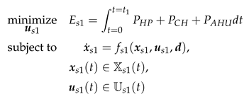
The state variables are the temperature of the room , the external and internal wall layers , from floor and ceiling. The system inputs are the signals for controlling the heat pump and chiller , as well as those for the ventilation system, the bypass damper and the air change rate . The disturbances are defined by the occupancy signal , the ambient temperature , the black sky temperature , and the global irradiance on all four inclined surfaces . An occupancy of the room is assumed from 7 am to 6 pm. The room temperature is set to a value of at the beginning of the simulation. All other initial temperatures are not specified but are iteratively determined by the Modelica solver.
The following state and input constraints apply, chosen in accordance with DIN 18599-10 Table A.2:
2.2. Adsorption Cooling Scenario (2ACE)
Compared to the reference scenario, two adsorption cooling elements are additionally integrated into the west and east façades and connected to the zone in the adsorption cooling scenario. The system scheme is shown in Figure 1b. These elements reduce the cooling capacity required by compression cooling. Their areas are defined via the area ratios to the total façade area (, ), which are subject to parameter variation.
The system diagram of one adsorption cooling element is shown in Figure 3. This consists of a collector, adsorber, condenser, and evaporator. The collector is connected to the ambient temperature and the respective irradiance . When the collector is irradiated, it drives the desorption process from the adsorber to the condenser, the thermochemical cold storage is being charged. Subsequently if cooling is required, valves are opened and water is driven from the evaporator to the adsorber. The evaporator cools down, stores excess energy and provides cooling to the room when needed. First, it was intended that the adsorption cooling element will be integrated into a wall construction, for which the wall temperature is provided. However, in this study, it is set to a constant . The models of all components are described in the following subsections. Subsequently, the non-linear optimisation problem is summarised.
2.2.1. Collector
Following the relationship in Equation (7), the collector is modelled.
2.2.2. Base Model
The adsorber, condenser and evaporator all extend a common base model, see Figure 4a. This model defines the impact of incoming temperature, e.g., from the collector on the capacity of the aluminium casing , and the heat transfer from the casing to the adsorbent or vapour-liquid equilibrium (VLE) . Heat exchange with the environment or the room can be adjusted via the dynamic heat transfer coefficient h, allowing for suitable heat exchanger determination from the determined time series. Furthermore, heat transfer from the casing to the next element is defined by an insulation layer .
The casing material is consistently aluminium, and the insulation layer is a vacuum insulation panel. Material and geometric properties were created based on the geometries presented in the study [22]. Table A5 provides an overview of the used parameter values (, , ), which are related to the area of the solar cooling element .
2.2.3. Adsorber
The adsorber model is depicted in Figure 4b. It extends the base model with the adsorbate model and diffusion resistances to the evaporator and condenser, implemented using the first version of the SorpLib Modelica library [15].
The adsorbate model solves the mass and energy balance of the adsorbate, investigating the working pairs Zeolite 13X - water and Silica Gel SG123 - water. The Dubinin-Astakhov equation is used as the characteristic curve, with adsorbent mass determined via the bulk density and cavity volume . The cavity volume, related to the element area, is .
Mass flows due to diffusion are described according to Glueckauf’s linear driving force approach, cf. Equation (8). Consistent with the thesis [21], no diffusion resistance due to pressure loss is considered. The two mass flows per adsorption cooling element are regulated via a continuous valve signal, with constraints ensuring mass flow only occurs from the evaporator to the adsorber and from the adsorber to the condenser.
The coefficients of the Dubinin-Astakhov equation and the material parameters of Zeolite 13X and Silica Gel SG123 were taken from the thesis [21], and are given in Table A6. During this study, the Dubinin-Astakhov equation proved to converge more reliably to a solution for the dynamic optimisation problem than the Dubinin-Lorenzian-Cumulative equation. However, different characteristic curves were used in the thesis [21], thus the coefficients of the Dubinin-Astakhov equation were adjusted to match the given characteristic curves. Furthermore, the bulk density is not provided in the thesis [21]. Therefore, the bulk density of Silica Gel SG123 was taken from the study [26], and the bulk density of Zeolite 13X was determined based on the masses given in the thesis [21].
2.2.4. Evaporator & Condenser
The evaporator and condenser model is depicted in Figure 4c. They consist of a cavity volume , which is surrounded by a casing. The cavity volume is given by the thickness and the element area . A thickness of was assumed for the condenser and for the evaporator. The cavity volume contains water in vapour liquid equilibrium (VLE), implemented using the first version of the SorpLib Modelica Library [15]. The liquid condensing in the condenser is pumped back to the evaporator by a pump if required, although this functionality is not utilised as only one day is considered, with the pump signal continuously set to zero. The fluid properties of water were taken from the NIST Chemistry WebBook [27], fitted to a Taylor series of order , and integrated into the adsorber, condenser and evaporator models.
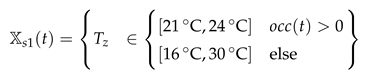
2.2.5. Dynamic Optimisation
The non-linear optimisation problem for the adsorption cooling scenario (s2), cf. Equation (9), extends the optimisation problem presented in Section 2.1.3.
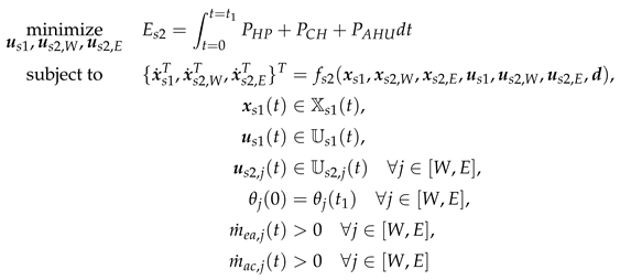
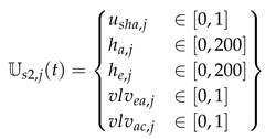
Adding the two adsorption cooling elements introduces nine additional states per element j. These comprise the temperatures of the casings, the adsorbate and the VLE, as well as the relative loading of the adsorbate and the densities of the VLE mixtures . Initially, the two adsorber temperatures are set to 60 °C and the temperatures of the condenser and evaporator to 21 °C. The initial densities of the vapour-liquid equilibria are determined via liquid volume fraction of . The relative initial loadings are determined based on an initial loading study presented in the following sub-section.
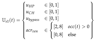
Furthermore, five additional inputs are added for each adsorption cooling element. The manipulated variables are the shading factor of the collector , the heat transfer coefficients for adsorber and evaporator (), and the valve positions from and to the adsorber (). For simplicity, the heat transfer coefficient from the condenser to the environment is set to a constant value of W m−2 K.
A final state constraint applies to the loadings to ensure comparability of the cooling storage potentials. Additionally, a mass flow constraint is set for each element from the evaporator to the adsorber and from the adsorber to the condenser to prevent backflow. Furthermore, the following input constraints apply for each element j:
2.2.6. Initial Loading Study
Due to numerical instability in the dynamic optimisation problems, some samples initially failed to converge. Primarily, the errors “Maximum_Iterations_Exceeded” or “Restoration_Failed” was reported, relating to issues in satisfying all boundary conditions. Within this context, each sample was analysed with an initial loading study, and only for the adsorption cooling scenario was the time step increased from 15 to 60. The initial loading study was introduced for two reasons. Firstly, the convergence of the dynamic optimisation problem for the adsorption cooling element is highly dependent on the initial loadings. Secondly, the choice of initial loading significantly impacts the final energy consumption.
The initial loading study conceptually extends the optimisation variables of the minimisation problem in dynamic optimisation to include the two relative initial loadings. If dynamic optimisation does not converge, the energy consumption of the reference scenario is applied. The following optimisation problem is solved:
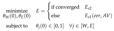
All initial loading studies are conducted with the optimisation framework Optuna [28] with the attributes n_startup_trials=20 and n_trials=50.
2.3. Photovoltaic Scenario (2PV)
The system configuration for the photovoltaic scenario is shown in Figure 1c. Here, two PV modules are integrated into the west and east façades instead of the adsorption cooling elements. Their areas are defined via the area ratios to the total façade area (, ). The electricity production of these elements reduces the electricity consumption. Excess electricity is not used or fed into the grid.
The electrical power output from both PV modules is determined using the temperature dependent model (Equations 1-2, [29]). The parameter values are given in Table A7.
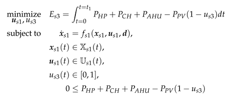
2.3.1. Dynamic Optimisation
Within the dynamic optimisation, the non-linear optimisation problem (14) is solved. This differs from the optimisation problem (1) in the objective function in that the PV feed-in is subtracted from the demand. As no battery and excess electricity production are considered, the PV feed-in is only taken into account as long as the objective function remains greater than zero. This is regulated by the additional input and the constraints. Otherwise, the same states, inputs and constraints apply as for the reference scenario.
2.4. Photovoltaic Plus Battery Scenario (2PVB)
The fourth scenario differs from the 2PV scenario by the addition of a battery. The PV yield is modelled identically. A PV module is also integrated into the west and east façades. Their areas are defined by the area ratios to the total façade area (, ).
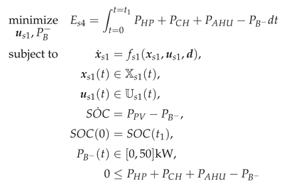
2.4.1. Dynamic Optimisation
Within the dynamic optimisation, the non-linear optimisation problem (15) is solved. This differs from the optimisation problem (14) in the objective by not regulating the PV production with the signal . Instead, the discharge power of an additional battery is optimised and integrated into the objective. The upper limit of the discharge power is chosen such that it is not reached for any of the examined data points. Periodic boundary conditions for the state of charge are set. Initially, the dynamic optimisation starts from a state of charge . Negative states of charge are allowed. Subsequently, the initial state of charge and the maximum stored energy are determined by shifting the charge curve upwards by the minimum state of charge. Otherwise, the same states, inputs, and constraints apply as in the reference scenario.
3. Results
In this section, the results of several parameter variations are presented. These variations include the area ratios of the respective solar cooling elements in the west and east façades (), the energy efficiency ratio of the compression cooling , and the façade area to room volume ratio . These investigations are applied to all four presented scenarios. The self-sufficiency level is introduced as the central comparison metric, cf. Equation (16). It describes to what extent the electrical energy consumption of the considered scenario is lower than that of the reference scenario. It thus represents the ability of a scenario to supply the necessary amount of power independently of the grid. At 100%, no additional external power is needed, the power produced equals the power consumed. At 0%, the considered scenario offers no advantage.
In the first sub chapter, the required energy consumption of the reference scenario at standard conditions are presented. Subsequently, the impact of the parameters (, , , ) on the self-sufficiency level of all investigated scenarios is examined.
Given that the area ratios (, ) are the subject of parameter variation, they are determined from intermediate variables that are easier to understand. These intermediate variables are the balance ratio and the total area ratio . The balance ratio indicates how the total area is distributed between the west and east elements. If the total area is assigned to the west element, the balance ratio is . If the focus is solely on the east element, the balance ratio is . The total area ratio indicates the overall capacity for solar cooling. Due to the constant window area ratios with , the area ratios of the solar cooling elements (, ) are limited. Therefore, not all balance ratios are evaluated for a total area ratio .
3.1. Energy Consumption of the Reference Scenario at Standard Conditions
Figure 5 presents the optimal time series of the reference scenario for the standard conditions (, ). Figure 5a shows the total electrical energy consumption, which increases during the occupancy period and amounts to by the end of the day. Figure 5b displays the floor area-specific thermal cooling power of the compression chiller, which only occurs during occupancy. The lowest value is W m−2. Figure 5c shows the room temperature, the upper and lower room temperature limits, and the ambient temperature. Starting from the initial value, the room temperature remains near the upper limit for most of the occupancy period, with constraints being met. Figure 5d depicts the bypass signal, the air change rate, and its upper and lower limits. The air change rate increases when the room temperature reaches the upper limit and cooling power is required. Otherwise, it is tied to the lower constraint. The bypass is fully utilised during the morning cooling period but is not relevant in other time periods, as the air change rate is zero.
3.2. Influence of Adsorbent and Both Area Fractions (, ) on the 2ACE Scenario
For this parameter variation, the energy efficiency ratio of the compression refrigeration machine and the façade area to room volume ratio are kept constant at standard conditions (, ).
The results for the self-sufficiency level for both adsorbent materials are presented in Figure 6. The maximum self-sufficiency level at a constant total area fraction is indicated by a star. Applying the initial loading study to all 144 data points in Figure 6 requires a computation time of 11.8 days.
For the adsorbent Zeolite 13X, cf. Figure 6a, the self-sufficiency level rises with increasing total surface area ratio . When , equivalent to a total area , the maximum self-sufficiency level is attained. At constant total area , the self-sufficiency level shows no pronounced maximum behaviour. No clear trend is discernible with respect to the balance ratio .
In comparison, the use of the adsorbent Silica Gel SG123, cf. Figure 6b, exhibits a greater increase in the self-sufficiency level with total area. Beyond a ratio of , the same maximum self-sufficiency level is achieved. Until the maximum self-sufficiency level is reached, using Silica Gel SG123 therefore results in near twice the self-sufficiency for the same total area . Regarding the balance ratio, no pronounced maximum behaviour is observed either. A balanced ratio tends to lead to increased self-sufficiency compared to exclusive distribution on one orientation.
In Figure 7, the relative initial loadings obtained from the initial loading studies are now considered, with the initial loadings for the west adsorber represented by a solid line and for the east adsorber by a dashed line.
For the adsorbent Zeolite 13X, cf. Figure 7a, a relative initial loading of for both the east and west adsorbers tends to yield optimal results within the initial loading studies. However, this applies only to a limited extent within the middle range of the balance ratio . No clear dependence on the total area ratio is discernible. For the adsorbent Silica Gel SG123, initial loadings are predominantly chosen, with no clear correlation to the balance ratio or the total area ratio observable.
3.3. Influence of Both Area Fractions (, ) on the 2PV and 2PVB Scenarios
Figure 8 presents the results of the parameter variation of the area fractions (, ) on the photovoltaic scenarios. Calculating all 272 data points in Figure 8 requires approximately 5.5.
Photovoltaic Scenario (2PV)
Figure 8a shows the results of the self-sufficiency level of the 2PV scenario when varying the balance and total area ratios. As with the adsorption cooling scenario, increasing the total area fraction generally leads to increased self-sufficiency. The 2PV scenario delivers lower self-sufficiency than the adsorption cooling scenario with the adsorbent Silica Gel SG123, cf. Figure 6b, for total area ratios . Subsequently, the self-sufficiency level increases to a value higher than the 2ACE scenario. The maximum self-sufficiency level is achieved at the maximum area ratio . For constant total area ratios, a continuous and pronounced maximum behaviour of the self-sufficiency is observed. The maximum curve is less pronounced for small total surface areas and subsequently more pronounced and shifted towards the western façade element. As the total area ratio continues to increase, the maximum shifts towards an even distribution of element areas . Generally, a purely eastern distribution of the total area leads to a lower self-sufficiency level than a purely western distribution, the maximum always lies in between.
Photovoltaic Plus Battery Scenario (2PVB)
Figure 8b shows the results for the 2PVB scenario. The self-sufficiency increases with the total area ratio of the two elements, as with the other two scenarios. From a total area ratio , complete self-sufficiency applies consistently. However, up to this total area ratio, a purely eastern distribution results in higher self-sufficiency than for the western element or a balance between them. This maximum prominence increases slightly with the total area ratio .
To enable dynamic optimisation without specifying a start and end value for the battery capacity, the start and end capacity were set to zero, and a negative battery capacity was permitted. Following the dynamic optimisation, the state of charge profile of the battery is corrected by the minimum value, from which the initial and maximum state of charge were derived, cf. Figure 9.
The behaviour of the initial battery capacity , cf. Figure 9a, is divided by the total area ratio . Up to the ratio , a clear minimum behaviour is observed with the balance ratio . The initial battery capacity decreases with increasing area focus on the east element. Above an area ratio , a minimum behaviour is observed within the range of the middle balance ratios. This initial capacity initially decreases with the increasing ratio and then increases again.
The maximum capacity is shown in Figure 9b. It exhibits a pronounced minimum behaviour between a balance ratio of 0.2 to 0.4 and then rises sharply with the balance ratio. Above a total area ratio of , the initially western focus crosses a saddle point. The minimum now shifts back to a balance ratio .
3.4. Influence of the Energy Efficiency Ratio ()
This section investigates the influence of the energy efficiency ratio of the vapor compression chiller. The balance ratio is held constant at and the façade area to room volume ratio at . The total area ratio of both elements and the energy efficiency ratio are varied. This analysis serves to enable an assessment of potentially temperature-dependent rather than constant energy efficiency ratios.
The results of the reference scenario are presented in Table 1. As the energy efficiency ratio increases, the energy consumption of the reference scenario decreases, requiring less electricity for the same cooling capacity.
In Figure 10, the results of the parameter variation are presented for all three scenarios. For the adsorption cooling scenario, the adsorbent Silica Gel SG123 was applied. As in the previous parameter variation, an increase in self-sufficiency is observed with the total area of both elements . For the 2ACE scenario, a slight influence of the energy efficiency ratio of the supporting compression chiller is shown. With increasing energy efficiency ratio, the sufficiency decreases slightly. For the other scenarios, energy efficiency ratio has a significant influence. With increasing ratio, the self-sufficiency increases. This leads, in the 2PVB scenario, to complete self-sufficiency being achieved with decreasing total area ratio. In the range , the 2ACE scenario consistently increases faster than the PV scenario. Consequently, the 2ACE scenario requires less total area to achieve the same self-sufficiency level. This also applies to the 2PVB scenario up to an energy efficiency ratio . However, compared to the photovoltaic scenarios, the 2ACE scenario is limited and never reaches complete self-sufficiency , as is the case with the 2PVB scenario.
3.5. Influence of the Façade Area to Room Volume Ratio ()
This section investigates the influence of the building type. The balance ratio is held constant at and the energy efficiency ratio at . The total area ratio of both elements and the façade area to room volume ratio are varied. This serves to classify the solar cooling potential for different building types.
The results for the reference scenario are given in Table 2. With decreasing ratio, the building’s edge length, façade area, floor area and energy consumption increase. The floor area increases more strongly than the façade area.
In Figure 11, the results of the parameter variation are presented for all three scenarios. The adsorption cooling scenario is also evaluated only for the adsorbent Silica Gel SG123. As observed in previous parameter variations, self-sufficiency increases with the total area of both elements . For all scenarios investigated, a decrease in the self-sufficiency ratio is observed with decreasing ratio, or increasing edge length of the square storey. More total area is required to achieve the same self-sufficiency level. Generally, the self-sufficiency level increases more strongly with the total area for the 2ACE scenario than for the two photovoltaic scenarios. Therefore, less area is required for the same self-sufficiency level. Furthermore, the 2ACE scenario is limited and the 2PVB scenario again achieves complete self-sufficiency .
4. Discussion
The results in Figure 6a,b show that Silica Gel SG123 is significantly more suitable for the 2ACE façade-integrated adsorption cooling concept than Zeolite 13X. This confirms the findings of the study [17]. Specifically, with the same total area, using Silica Gel SG123 achieves near double the self-sufficiency level compared to Zeolite 13X. In other words, achieving the same self-sufficiency level requires approximately twice the area when using Zeolite 13X. Therefore, hypothesis H1 is confirmed by the present results.
The results in Figure 6a,b also serve to assess hypothesis H2. For this purpose, the balance ratio was introduced to examine purely distributing the total area to the east or west element, as represented by the 1ACE concept, and balancing between both sides. The results do not confirm hypothesis H2. Neither solely allocating the total area to the west or east adsorbent, nor distributing it between both sides, leads to a maximum self-sufficiency level. This also indicates that the area focus of the solar cooling elements does not play a decisive role, contradicting the results of the previous study [12], which found that the orientation of the adsorption cooling element strongly influences self-sufficiency. However, the present study used a control concept based on dynamic optimisation, which presumably offers significantly increased flexibility and reliability when dealing with various system parameters, such as element alignment.
The highly fluctuating initial relative loadings in Figure 7a,b highlight the issue of convergence rate within the 2ACE scenario. No clear, consistent trend is discernible. Once the maximum self-sufficiency level is reached, multiple solutions for the initial conditions should consistently be found. The presence of multiple initial conditions below this maximum is likely due to insufficient iterations during optimisation. Increasing the number of trials, n_trials, could mitigate this. It is hypothesised that the objective function exhibits a very flat optimum.
Hypothesis H3 is not confirmed. Replacing the adsorption cooling elements with PV elements results in a significantly lower self-sufficiency level, assuming Silica Gel SG123 is used, at least up to a total area ratio of . But, the results in Figure 8a show that the self-sufficiency of the photovoltaic scenario then continues to increase, while the adsorption cooling scenario stagnates. This is because adsorption cooling can only provide cooling energy and not electrical power for the decentralised ventilation system, meaning this share of electrical energy consumption cannot be independently compensated for in the adsorption cooling scenario. However, if it is assumed that the conversion efficiency of electrical energy into cooling energy is lower due to the high ambient temperature on the hottest day of the year, the adsorption cooling scenario is more self-sufficient than the PV scenario, as shown in Figure 10a,b. Therefore, the adsorption cooling scenario appears more robust.
Adding a battery to the photovoltaic scenario leads to a decoupling of the area balance and a surprisingly significant increase in self-sufficiency. The results in Figure 8b show that a total area of is sufficient to operate the system completely independently of the west-east division. This also holds true when a lower energy efficiency ratio is assumed, as shown in Figure 10c. For the 2PVB scenario to achieve a comparable self-sufficiency level to the adsorption cooling scenario in the range of small total areas , the energy efficiency ratio should not fall below .
The results in Figure 9a show that solely allocating the PV area to the east adsorbent leads to a lower initial state of charge . This is because electricity is generated by the east element in the morning and then depleted as the cooling demand rises. The battery capacity profile is reversed for a purely western allocation, as the battery is first discharged with the onset of cooling performance and then recharged by the west-oriented PV element.
The results in Figure 9b should be considered in detail, distinguishing between results with and without complete self-sufficiency . If complete self-sufficiency is not achieved , the maximum battery capacity is minimal for a balance ratio . The eastern PV element should be small and, together with an increased initial capacity, cover the morning cooling demand. The western element then replenishes the energy storage in the afternoon. With complete self-sufficiency, it must be assumed that too much electricity is stored in the battery, increasing the maximum capacity. To meet the periodic boundary condition, this excessive storage is discharged at the end of the day by over-conditioning the room, leading to a slight drop in maximum battery capacity after and then a sharp increase. However, if feeding into the power grid is permitted but not remunerated, the maximum battery capacity could be reduced, and a capacity lower than the saddle point of approximately could suffice.
The assessment of hypothesis H5 is made with the results in Figure 11. Generally, energy demand increases with decreasing -ratio, specifically an increased ratio of floor area to façade area. The heat sources are determined by the façade area, resulting in solar thermal and convective heat gains, and also by the floor area, including heat input from ventilation and internal gains. However, the heat sinks are solely related to the façade area. With a decreasing -ratio, the relationship between façade-related heat sinks and floor area-related heat sources changes. The façade-related heat sources are no longer sufficient, resulting in increased electricity consumption from the grid for compression cooling, thus reducing the self-sufficiency level with decreasing -ratio. Therefore, regardless of the scenario, slender buildings can be operated more autonomously than broad or deep buildings. Hypothesis H5 is thus confirmed, consistent with the results of the study (Figure 2, [13]).
The consistently high self-sufficiency level of the adsorption cooling scenario should be viewed critically. For this study, a very high heat conductance G between the casing and the adsorbent was assumed, see Table A5. If this heat conductance is lower, the self-sufficiency should be significantly reduced.
Various measures were taken in this study to ensure the convergence of the dynamic optimisation of the 2ACE scenario:
- The pump signal and the heat transfer of the condenser were set to constant values.
- If or , reduced system models were created, reducing the number of inputs, states and constraints.
- The time step of the adsorption cooling scenario simulations was increased from 15 to 60min.
Even this extensive preliminary study did not lead to the successful convergence of all data points. Therefore, each data point in the results was simulated with an initial loading study, which considerably increased the simulation time for each sample. Despite this, fewer than 5 data points remained, which converged but yielded unrealistically high self-sufficiencies. These were recalculated.
4.1. Limitations & Future Work
Future work should therefore focus on the convergence rate of the dynamic optimisation of the adsorption cooling scenario. This could be achieved, firstly, by using different solvers. In the current study, both valve positions are mapped as system inputs. One possibility would be to solve the valve positions as integer variables in the dynamic optimisation via a mixed-integer non-linear program (MINLP) solver. However, this is currently not possible with Modelon Impact. Another possibility could be to reduce the number of system inputs and constraints by, for example, implementing the valves as self-regulating flap valves. This would eliminate two inputs and two constraints per adsorption cooling element. However, the problem of continuous differentiability of all sub-models caused by flap valves would need to be resolved.
The time step has a direct influence on the number of optimisation variables in the dynamic optimisation problem. Increasing it results in greater flexibility in utilising the potential of the adsorption cooling elements. Therefore, future work should also focus on reducing the time step, which should directly impact the self-sufficiency level.
So far, only one day, the hottest day of the year, has been considered. If the simulation time can be reduced, different prediction horizons deviating from 24 should be considered. In addition, a model predictive control concept should be derived using this dynamic optimisation and applied to an entire summer or year.
To ensure an even more accurate comparison between the data points, all initial should correspond to the final state values, as implemented in the dissertation [20]. Due to the challenging convergence of the dynamic optimisations, periodic boundary conditions were not implemented for all states but only for the adsorbent loading and battery capacity. Future studies should investigate this aspect further.
In this study, the substance pair Zeolite 13X-water and Silica Gel SG123-water were implemented. Future work should investigate the suitability of other substance pairs for this façade-integrated adsorption cooling concept. Furthermore, the heat transfer from the collector surface to the adsorbent should be investigated in greater detail.
System models were developed and used for dynamic optimisation in this study. Future work should simultaneously optimise static design parameters and dynamic inputs. This could be done, for example, with the objective of a holistic life cycle assessment combining grey and operational emissions over a defined life cycle period. This may offer advantages over the photovoltaic plus battery scenario, as the adsorption cooling element does not require rare earth materials. In addition to the coupled life cycle analysis based on dynamic optimisation of static and dynamic system variables, the availability and recyclability of raw materials should also be included in the decision-making process.
5. Conclusions
In this study, various concepts for façade-integrated solar cooling were presented and optimally operated using dynamic optimisation for the hottest day of the year at the considered location.
In the first step, the system models of all considered scenarios are presented. These are the reference scenario without solar cooling elements, the adsorption cooling scenario with two adsorption cooling elements, the photovoltaic scenario with two photovoltaic elements and the photovoltaic plus battery scenario. For each scenario, the underlying system equations and the dynamic optimisation problem were presented. This includes the description of the objective function, states, inputs, initial conditions and constraints.
In the results section, the influence of the adsorbent and four system parameters on the self-sufficiency level is investigated. These system parameters include the balance ratio , which determines the area focus between the west and east sides of the two solar cooling elements, the total area ratio , which determines the cooling capacity, the energy efficiency ratio of a supporting compression chiller and the façade area to room volume ratio , which represents the slenderness of the building type.
The results show that the adsorbent Silica Gel SG123 is significantly better suited for the present application than Zeolite 13X. By using Silica Gel SG123, the same self-sufficiency level can be provided with half the area of all solar cooling elements.
As in previous studies, the ability to provide off-grid cooling increases strongly with the total area of the solar cooling elements . However, no pronounced optimal area balance between the east and west adsorbers is observed. This is likely due to the flexibility enabled by the control concept of dynamic optimisation.
Compared to the scenario with solely compression cooling and two photovoltaic elements, a significantly lower self-sufficiency level is observed. Adding a battery to the photovoltaic scenario not only significantly increases the self-sufficiency level but also enables complete self-sufficiency with electricity.
Up to a total area ratio of , the adsorption cooling scenario usually leads to a higher self-sufficiency than the photovoltaic scenarios. Furthermore, the adsorption cooling potential is limited in its ability to provide itself with cooling, as the electrical energy required to operate the ventilation cannot be provided off-grid. This is where the photovoltaic scenarios have a decisive advantage. They produce electrical energy which can be used to operate the ventilation and provide cooling.
For slender buildings with a high AV-ratio, relatively less façade area is required for solar cooling elements than for broad buildings with a low AV-ratio. This is because the floor area increases more strongly than the façade areas, whereby the heat sources exceed the façade area-related heat sinks.
The main limitations of the adsorption cooling scenario remain its convergence rate. The initial loading study introduced is very time-consuming and should be replaced by a coupled optimisation of dynamic and static system variables. Subsequently, prediction horizon lengths should be analysed and model predictive control concepts should be derived and examined over a period of months of operation.
Author Contributions
Conceptualization, S.W.; methodology, S.W.; software, S.W.; validation, S.W.; data curation, S.W.; writing—original draft preparation, S.W.; writing—review and editing, S.W. and P.L.; visualization, S.W.; supervision, P.L.; project administration, P.L.; funding acquisition, P.L. All authors have read and agreed to the published version of the manuscript.
Funding
This study was supported by the German Research Foundation (DFG, Deutsche Forschungsgemeinschaft, Project-ID 279064222), as a part of the collaborative research centre CRC1244 (SFB1244) “Adaptive Skins and Structures for the Built Environment of Tomorrow” sub-project C06 “Adaptive, façade-integrated adsorption systems for thermal management of lightweight buildings”.
Data Availability Statement
The full Python and Modelica source code as well as the data underlying the result figures are publicly available under the data repository of the University of Stuttgart https://doi.org/10.18419/DARUS-5666.
Acknowledgments
During the preparation of this study, the authors used Google Gemma3 for translation and linguistic comprehensibility. Additionally, the OpenAI GPT-4.1 tool was used for the purposes of Python coding assistance. The authors have reviewed and edited the output and take full responsibility for the content of this publication.
Conflicts of Interest
The authors declare no conflicts of interest.
Abbreviations
The following abbreviations are used in this manuscript:
| CRC1244 | Collaborative Research Center 1244 at the University of Stuttgart |
| Hi | Hypotheses i |
| VLE | vapor liquid equilibrium |
| 1ACE | concept with one adsorber, condenser and evaporator |
| 2A1CE | concept with two adsorber, one condenser and evaporator |
| 2ACE | concept with two compact elements, each with one adsorber, condenser and evaporator |
| 2PV | concept with compression cooling and two photovoltaic elements |
| 2PVB | concept with compression cooling and two photovoltaic elements plus one battery |
Nomenclature
| Variables: | ||
| Symbol | Description | Unit |
| r | area ratio, i.e., | 1 |
| t, | time, time step width | |
| b, h | edge length, height of the square room geometry | |
| A | area | m2 |
| AV | façade area to room volume ratio | |
| occ | occupancy signal | 1 |
| , | coefficient of performance, energy efficiency ratio | 1 |
| u | dimensionless input signals | 1 |
| air change rate | ||
| specific heat flow | W m−2 | |
| P, | electrical, thermal power | |
| volume flow | ||
| T | temperature | °C |
| p | pressure | |
| I | irradiance | W m−2 |
| vlv | valve signal | 1 |
| h | heat transfer coefficient | W m−2 K |
| λ | heat conduction coeffcient | W m−1 K |
| ρ | density | |
| c | specific heat capacity | |
| C | heat capacity | |
| G | heat conductance | |
| Deff | effective diffusion coefficient | m2 s−1 |
| βLDF | intra-particle mass transfer coefficient | s−1 |
| dsph | diameter of the adsorbent grain | |
| θ | relative water loading | 1 |
| state of charge | ||
| SL | self-sufficiency level | % |
| E | total daily electrical energy consumption of the scenario | |
| , x, u, d | vector of state derivatives, states, inputs and disturbances | - |
| f | differential-algebraic system of equations of a scenario | - |
| , | collection of state and input constraints | - |
| Subscripts: | |
| Symbol | Description |
| W, E | west, east |
| win, ext, int, sce | window, external wall, internal wall, solar cooling element |
| col, a, c, e | collector, adsorber, condenser, evaporator |
| cas, ins, cav | casing, insulation, cavity |
| bal, tot | balance, total |
| HP, CH, AHU, PV | signal of the heatpump, chiller, air handling unit, photovoltaic |
| s1, s2, s3, s4 | reference, adsorption cooling, photovoltaic, photovoltaic plus battery scenario |
| inf, ven | infiltration, ventilator |
| nom | at nominal conditions |
| battery discharge capacity | |
| sha | shading of the collector |
| pmp | pump signal |
| z | zone |
| amb, bs | ambient, black sky |
| gti | global tilted irradiance |
| ll, ul | lower or upper limit |
Appendix A. General Settings and Material Properties
Appendix A.1. Envelope Properties
The window area is divided into a frame and glazing component. The frame accounts for 8% of the total window area assigned via the window-to-wall ratio . The thermal transmittance of the frame is assumed to be .
The layer composition of the glazing is given in Table A1. This is defined according to the sun protection window “triple low-e argon deflected” in the WINDOW programme [30]. The following relationships apply:

Table A1.
Layer build-up and thickness of the glazing from the outside to the inside.
| material | low-e-1 | air-10-argon-90 | clear | air-10-argon-90 | low-e-2 |
|---|---|---|---|---|---|
| thickness | 5.7 | 12.7 | 5.7 | 12.7 | 5.7 |
The properties of the gas layers were taken from ISO 52022-3 Table F.1, assuming a mixture ratio of 10% air and 90% argon. For simplification of the dynamic optimisation, the Nusselt number was set to 1 for modelling the gas gap. The spectral material properties of the layers are presented in Table A2 and taken from the WINDOW program.
Table A2.
Spectral material data of the glazing layers.
| material | |||||
| low-e-1 | 0.362 | 0.305 | 0.463 | 0.84 | 0.035 |
| low-e-2 | 0.362 | 0.463 | 0.305 | 0.035 | 0.84 |
| clear | 0.771 | 0.07 | 0.07 | 0.84 | 0.84 |
The layer composition of the four external walls is given in Table A3. The ceiling and floor are considered as internal walls, modelled as a 13 thick layer of concrete.
Table A3.
Layer build-up and thickness of the external walls from the outside to the inside.
| material | aluminum | mineral wool | aluminum |
|---|---|---|---|
| thickness | 2 | 200 | 2 |
The material data are presented in Table A4. According to the summer conditions in ISO 52022-3 (Chapter 6.4.6), the external and internal heat transfer coefficients are set constant for all envelope elements, with W m−2 K and W m−2 K respectively.
Table A4.
Material data of the external and internal walls.
| material | c | ||||
| aluminum | 0.9 | 0.05 | 2700 | 900 | 200 |
| mineral wool | 0.6 | 0.9 | 24 | 1030 | 0.032 |
| concrete | 0.5 | 0.9 | 2500 | 1000 | 2.5 |
Appendix A.2. Adsorption Cooling Element Properties
Table A5 lists all constant parameters used in the models of the adsorber, condenser and evaporator.
Table A5.
Properties of the adsorber, condenser and evaporator models.
| casing | insulation | ||||||
| c | |||||||
| adsorber | 27192 | 697333 | |||||
| condenser | 200 | 2700 | 900 | 14896 | 270667 | 0.003 | 0.15 |
| evaporator | 14896 | 270667 | |||||
Table A6 lists all Dubinin-Astakhov parameters for both working pairs, namely the characteristic energy , the exponent n, and the maximum pore volume filling . The Dubinin-Astakhov parameters for Zeolite 13X apply to adsorption enthalpies smaller than 500/, and for Silica Gel SG123 smaller than 200/.
Table A6.
Parameter of the Dubinin-Astakhov equation as well as material parameters of both working pairs.
Table A6.
Parameter of the Dubinin-Astakhov equation as well as material parameters of both working pairs.
| n | c | |||||||
| Zeolite 13X | 1608.69 | 1.110 | 0.29618 | 582 | 960 | 1.4 | 3.4e-10 | 2.8e-9 |
| Silica Gel SG123 | 193.90 | 1.921 | 0.41178 | 710 | 1000 | 0.9 | 1.8e-10 | |
Appendix A.3. PV Panel
Table A7 lists all relevant parameter of the PV-model. The data were taken from the datasheet of the “SOLARWATT Panel vision GM 3.0 construct” module. A derating factor of was assumed.
Table A7.
Properties of the PV modules.
| 194.92 | 1 | -0.34 | 44 | 0.196 | 25 | 1000 |
References
- United Nations Environment Programme. 2021 Global Status Report for Buildings and Construction: Towards a Zero-emission, Efficient and Resilient Buildings and Construction Sector. Technical report, Nairobi, 2021.
- Santamouris, M. Cooling the buildings – past, present and future. Energy and Buildings 2016. [Google Scholar] [CrossRef]
- Attia, S.; Levinson, R.; Ndongo, E.; Holzer, P.; Berk Kazanci, O.; Homaei, S.; Zhang, C.; Olesen, B.W.; Qi, D.; Hamdy, M.; et al. Resilient cooling of buildings to protect against heat waves and power outages: Key concepts and definition. Energy and Buildings 2021. [Google Scholar] [CrossRef]
- Prieto, A.; Knaack, U.; Auer, T.; Klein, T. COOLFACADE: State-of-the-art review and evaluation of solar cooling technologies on their potential for façade integration. Renewable and Sustainable Energy Reviews 2019. [Google Scholar] [CrossRef]
- Hamida, H.; Konstantinou, T.; Prieto, A.; Klein, T. Solar Cooling Integrated Façades: Key perceived enabling factors and prospects of future applications. Journal of Building Engineering 2023. [Google Scholar] [CrossRef]
- Prieto, A.; Klein, T.; Knaack, U.; Auer, T. Main perceived barriers for the development of building service integrated facades: Results from an exploratory expert survey. Journal of Building Engineering 2017. [Google Scholar] [CrossRef]
- Avesani, S.; Hallström, O.; Füldner, G.; Fedrizzi, R. Integration of Sorption Collector in Office Curtain Wall: Simulation Based Comparison of Different System Configurations. In Proceedings of the EuroSun Conference, Aix-les-Bains, France, 2014. [Google Scholar] [CrossRef]
- Prieto, A.; Knaack, U.; Auer, T.; Klein, T. Feasibility Study of Self-Sufficient Solar Cooling Façade Applications in Different Warm Regions. Energies 2018. [Google Scholar] [CrossRef]
- Wu, D.; Aye, L.; Yuan, Y.; Mendis, P.; Ngo, T. Comparison of optimal oriented façade integrated solar cooling systems in Australian climate zones. Solar Energy 2020. [Google Scholar] [CrossRef]
- Noaman, D.S.; Moneer, S.A.; Megahed, N.A.; El-Ghafour, S.A. Integration of active solar cooling technology into passively designed facade in hot climates. Journal of Building Engineering 2022. [Google Scholar] [CrossRef]
- Heidingsfeld, J.L.; Böckmann, O.; Schäfer, M.; Böhm, M.; Sawodny, O. Low Order Hybrid Model for Control Design of an Adsorption Facade System for Solar Cooling. In Proceedings of the IEEE Conference on Control Technology and Applications, Trieste, Italy, 2022. [Google Scholar] [CrossRef]
- Weber, S.O.; Böckmann, O.; Greiner, A.; Park, S.; Schäfer, M.; Leistner, P. Optimal operation and conceptual design of a novel façade-integrated adsorption cooling system. In Proceedings of the EUROSUN conference, Kassel, Germany, 2022. [Google Scholar] [CrossRef]
- Böckmann, O.; Borschewski, D.; Weber, S.; Schäfer, M. Simulation-based determination of system size and energy savings for a life cycle assessment of a facade-integrated adsorption system for solar cooling of buildings. In Proceedings of the BauSim conference, Wien, Austria, 2024. [Google Scholar] [CrossRef]
- Bau, U. From dynamic simulation to optimal design and control of adsorption energy systems. PhD thesis, RWTH Aachen University, Aachen, Germany, 2018. [Google Scholar]
- Bau, U.; Lanzerath, F.; Gräber, M.; Graf, S.; Schreiber, H.; Thielen, N.; Bardow, A. Adsorption energy systems library - Modeling adsorption based chillers, heat pumps, thermal storages and desiccant systems. In Proceedings of the 10th International Modelica Conference, Lund, Sweden, 2014. [Google Scholar] [CrossRef]
- Dubies, T.; Böckmann, O.; Schäfer, M. Material Study of a Facade-Integrated Adsorption System for Solar Cooling of Buildings. In Proceedings of the International Renewable Energy Storage and Systems Conference, Aachen, Germany, 2024. [Google Scholar] [CrossRef]
- Li, Q.; Boeckmann, O.; Schaefer, M. Systematic screening and evaluation for an optimal adsorbent in a facade-integrated adsorption-based solar cooling system for high-rise buildings. Energy 2024. [Google Scholar] [CrossRef]
- Gschweng, M.; Heidingsfeld, J.L.; Böckmann, O.; Schäfer, M.; Böhm, M.; Sawodny, O. Evaporator Temperature Control of a Solar-Powered Adsorption Façade System. In Proceedings of the IEEE Conference on Control Technology and Applications, Newcastle, United Kingdom, 2024. [Google Scholar] [CrossRef]
- Daiber, R.; Gschweng, M.; Sawodny, O.; Böhm, M. Control of an Adsorption Cooling Facade System – Deep Reinforcement Learning for a Hybrid Dynamical System*. In Proceedings of the American Control Conference, Denver, USA, 2025. [Google Scholar] [CrossRef]
- Gräber, M. Energieoptimale Regelung von Kälteprozessen. PhD thesis, Technical University of Braunschweig, Braunschweig, Germany, 2013. [Google Scholar]
- Lanzerath, F. Modellgestützte Entwicklung von Adsorptionswärmepumpen. PhD thesis, RWTH Aachen University, Aachen, Germany, 2014. [Google Scholar]
- Böckmann, O.; Marmullaku, D.; Schaefer, M. Dynamic Modeling and Simulation of a Facade-Integrated Adsorption System for Solar Cooling of Lightweight Buildings. Energies 2024. [Google Scholar] [CrossRef]
- Blandini, L.; Haase, W.; Weidner, S.; Böhm, M.; Burghardt, T.; Roth, D.; Sawodny, O.; Sobek, W. D1244: Design and Construction of the First Adaptive High-Rise Experimental Building. Frontiers in Built Environment 2022. [Google Scholar] [CrossRef]
- Wetter, M.; Zuo, W.; Nouidui, T.S.; Pang, X. Modelica Buildings library. Journal of Building Performance Simulation 2014. [Google Scholar] [CrossRef]
- Howell, J.R.; Mengüç, M.P.; Daun, K.J.; Siegel, R. Thermal radiation heat transfer, seventh edition ed.; CRC Press / Taylor & Francis Group: Boca Raton, 2021. [Google Scholar]
- Henninger, M.; Engelpracht, M.; Tuchlinski, D.; Ismail, M.; Bardow, A.; Seiler, J. Water, ethanol, or methanol for adsorption chillers? Model-based performance prediction from Infrared-Large-Temperature-Jump experiments. Applied Thermal Engineering 2024. [Google Scholar] [CrossRef]
- Lemmon, E.W.; Bell, I.H.; Huber, M.L.; McLinden, M.O. Thermophysical Properties of Fluid Systems. Eds. P.J. Linstrom and W.G. Mallard, National Institute of Standards and Technology, Gaithersburg MD, 20899.
- Akiba, T.; Sano, S.; Yanase, T.; Ohta, T.; Koyama, M. Optuna: A Next-generation Hyperparameter Optimization Framework. In Proceedings of the ACM SIGKDD International Conference on Knowledge Discovery & Data Mining, New York, USA, 2019. [Google Scholar] [CrossRef]
- Lu, J.; Wang, W.; Zhang, Y.; Cheng, S. Multi-Objective Optimal Design of Stand-Alone Hybrid Energy System Using Entropy Weight Method Based on HOMER. Energies 2017. [Google Scholar] [CrossRef]
- Curcija, C.; Vidanovic, S.; Hart, R.; Jonsson, J.; Powles, R. WINDOW Technical Documentation. Technical report, 2018.
Figure 1.
Schematic system diagrams of scenarios under investigation.
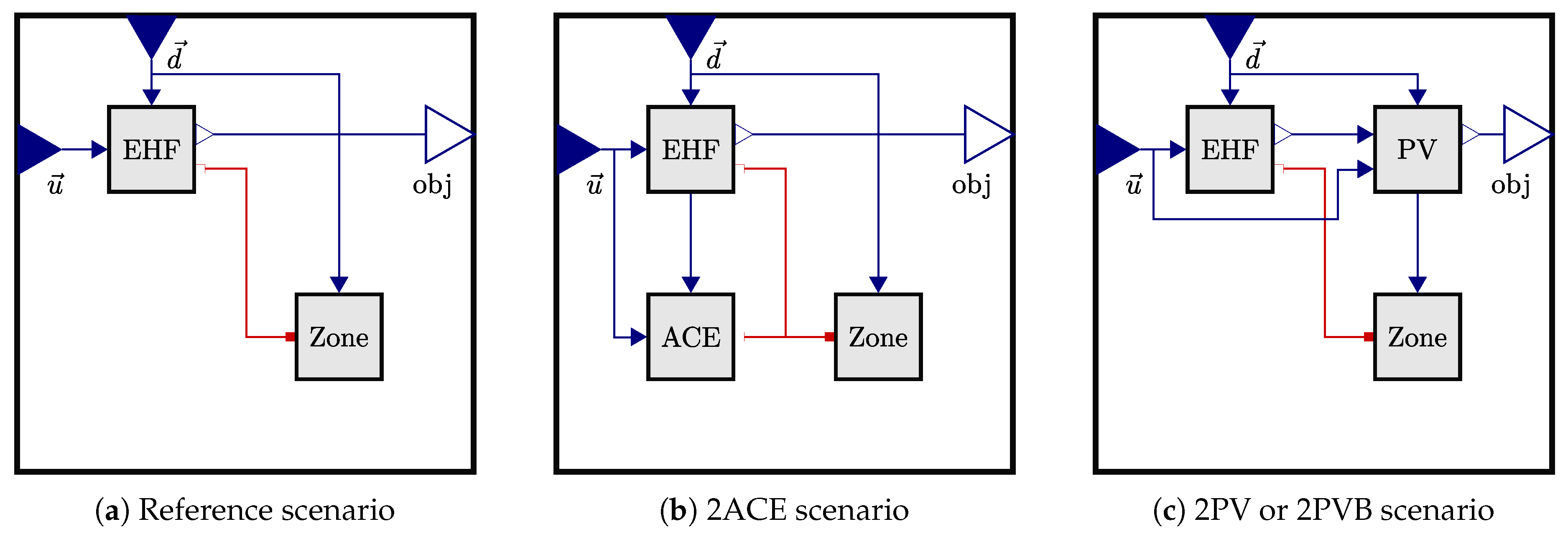
Figure 2.
Visual representation of the investigated space for the adsorption cooling scenario from two viewpoints. The solar cooling elements are highlighted in dark colour.
Figure 2.
Visual representation of the investigated space for the adsorption cooling scenario from two viewpoints. The solar cooling elements are highlighted in dark colour.
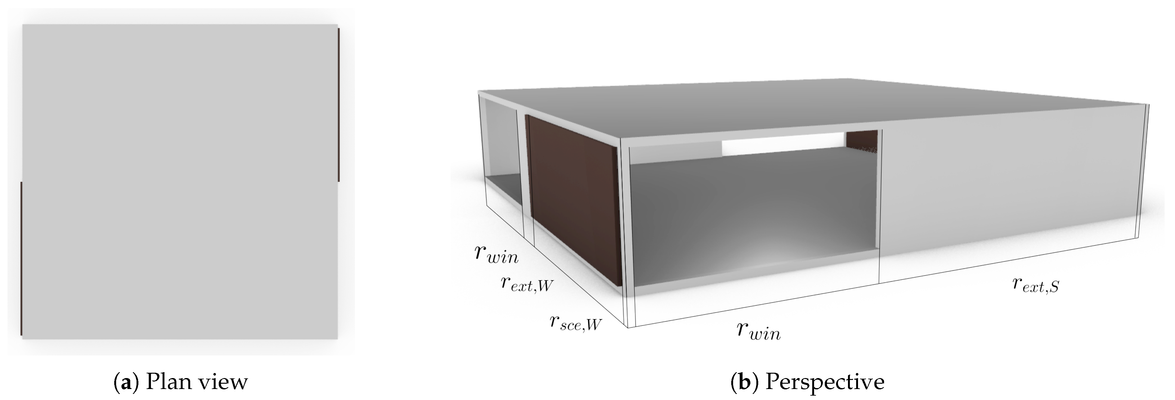
Figure 3.
System diagram of one adsorption cooling element.
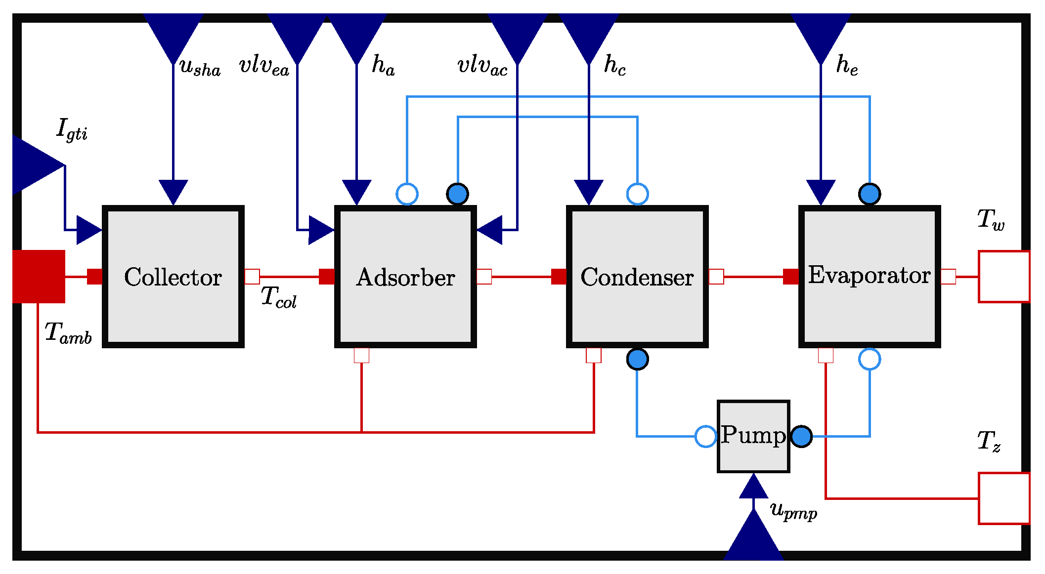
Figure 4.
System diagram of the base model, adsorber and condenser.
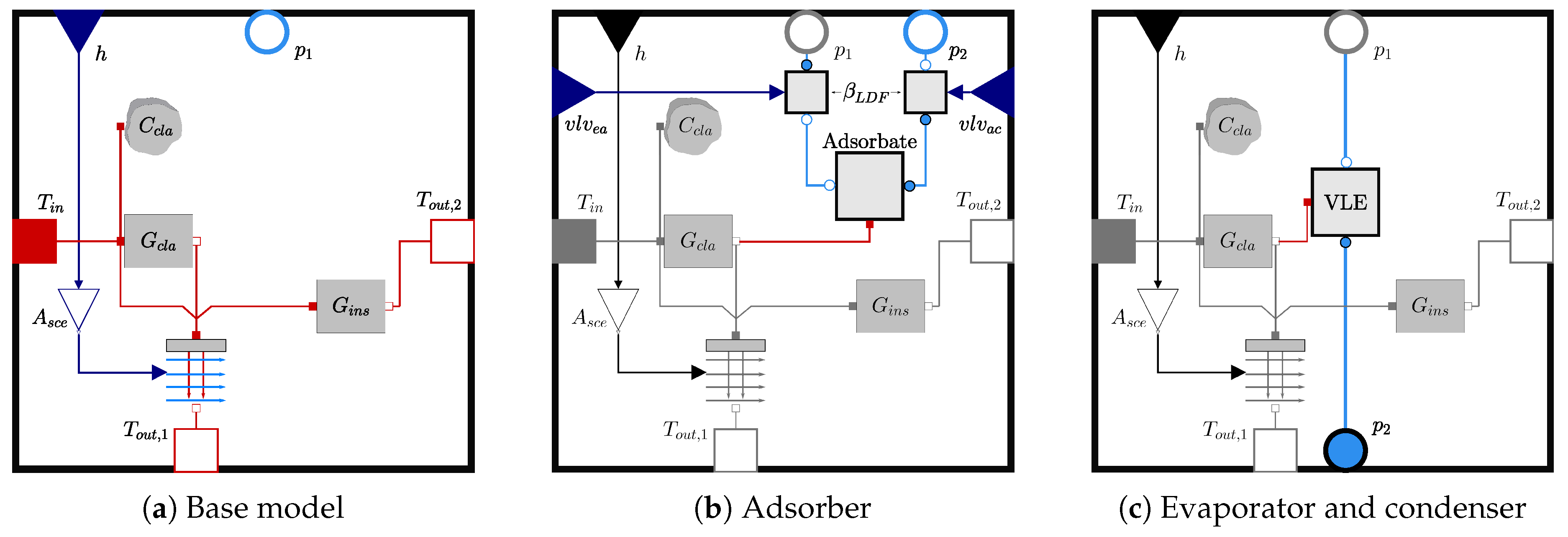
Figure 5.
Optimal trajectories of the reference scenario at standard conditions (, ).
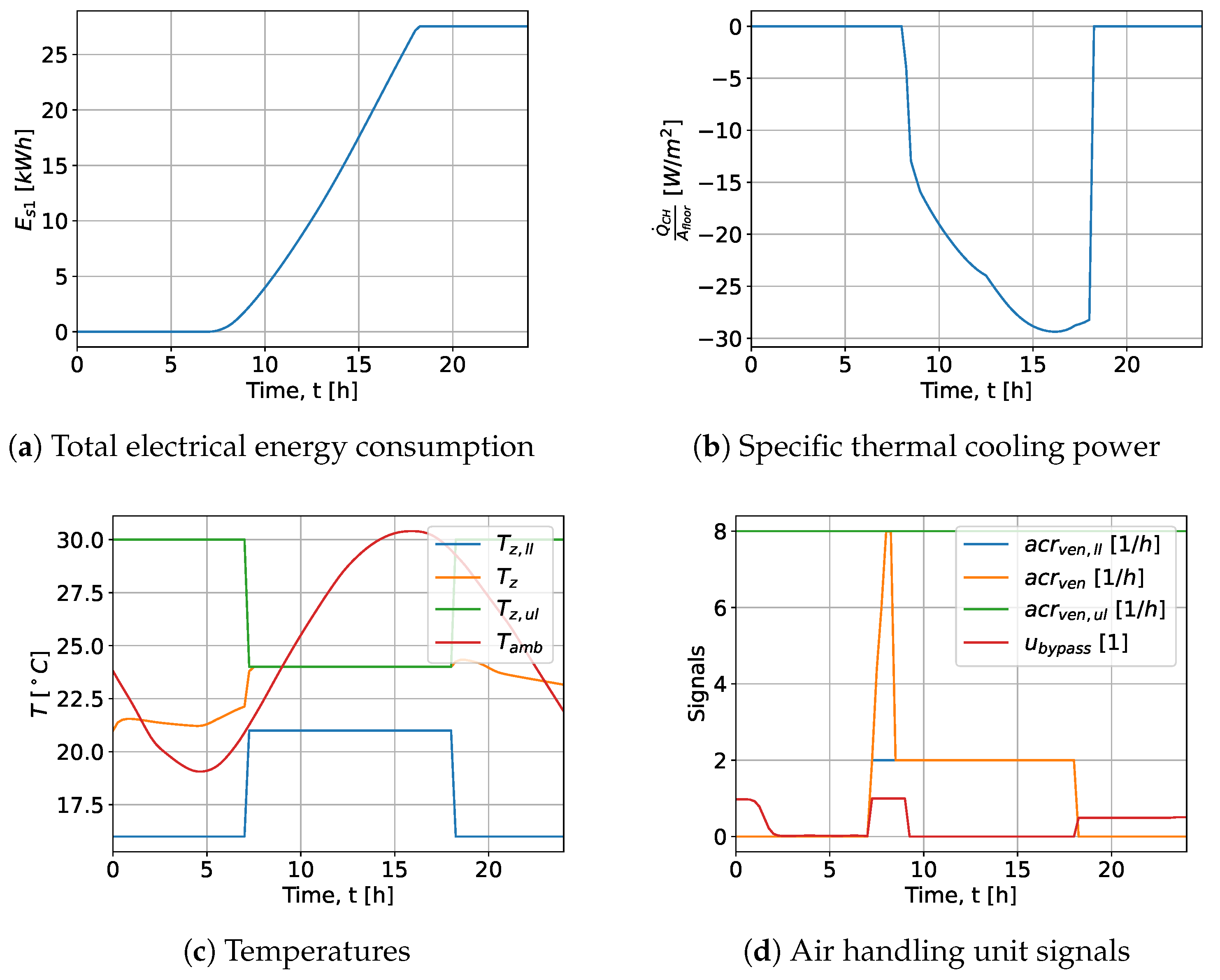
Figure 6.
Self sufficiency level of the 2ACE scenario for both adsorbents, different balance ratios and total element area .
Figure 6.
Self sufficiency level of the 2ACE scenario for both adsorbents, different balance ratios and total element area .

Figure 7.
Initial relative loading for both adsorbent materials, different balance ratios and total element area . The relative loading of the west element is solid and east dotted.
Figure 7.
Initial relative loading for both adsorbent materials, different balance ratios and total element area . The relative loading of the west element is solid and east dotted.
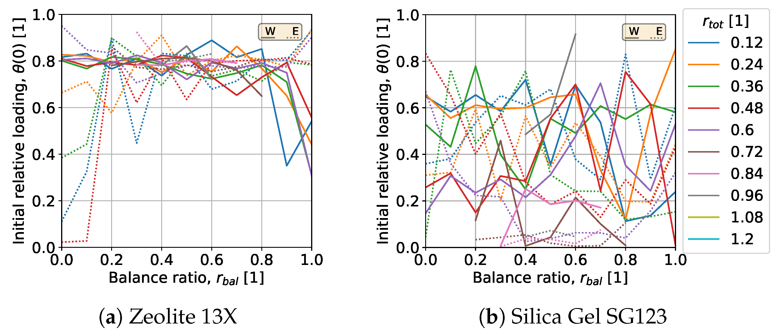
Figure 8.
Self sufficiency level of the 2PV and 2PVB scenarios for different balance ratios and total element area .
Figure 8.
Self sufficiency level of the 2PV and 2PVB scenarios for different balance ratios and total element area .
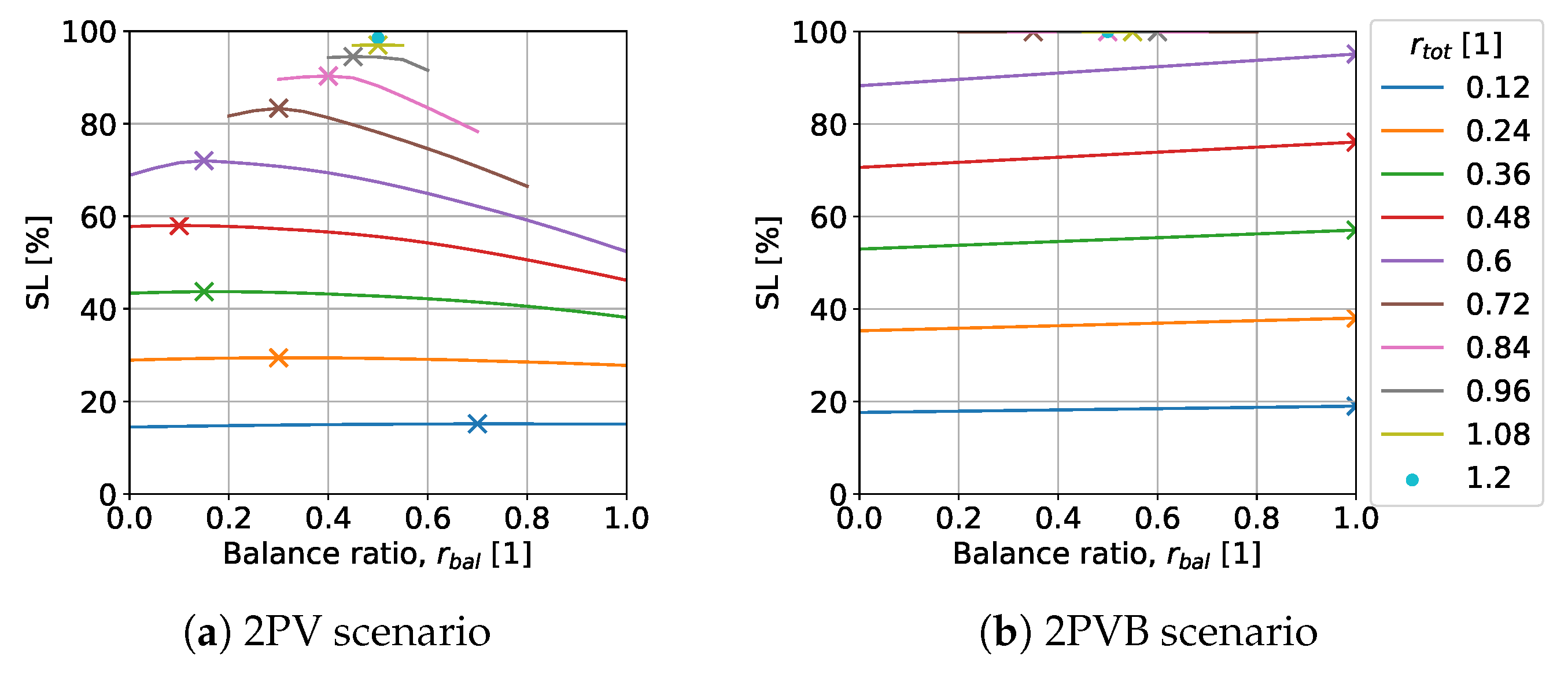
Figure 9.
Results of the initial and maximum battery capacity of the 2PVB scenario for both area fractions (, ).
Figure 9.
Results of the initial and maximum battery capacity of the 2PVB scenario for both area fractions (, ).
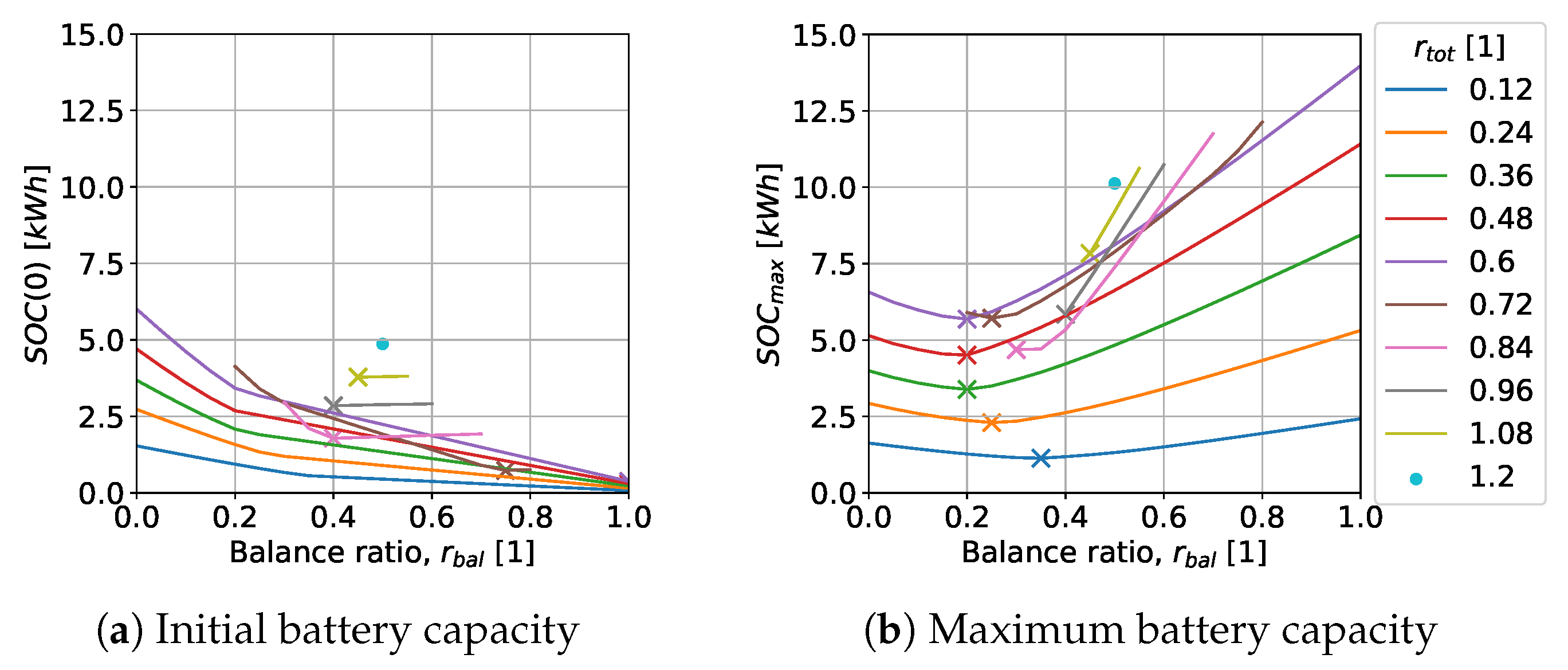
Figure 10.
Self sufficiency level for all scenarios for different energy efficiency ratios and total element area .
Figure 10.
Self sufficiency level for all scenarios for different energy efficiency ratios and total element area .
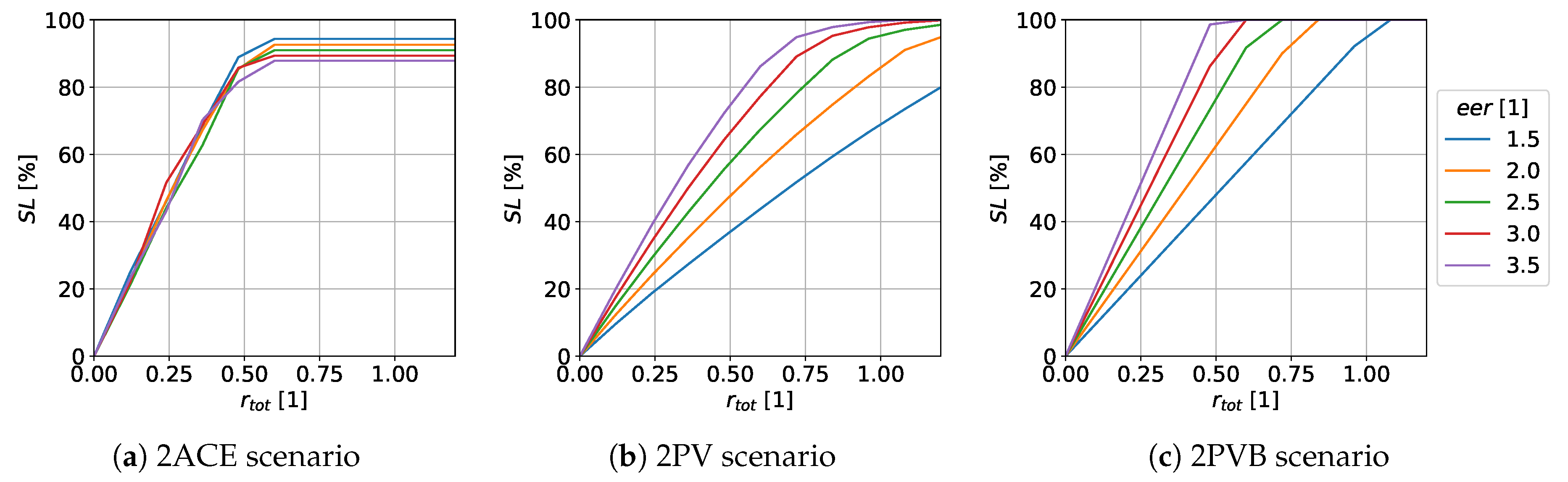
Figure 11.
Self sufficiency level for all scenarios for different façade area to room volume ratios and total element area .
Figure 11.
Self sufficiency level for all scenarios for different façade area to room volume ratios and total element area .
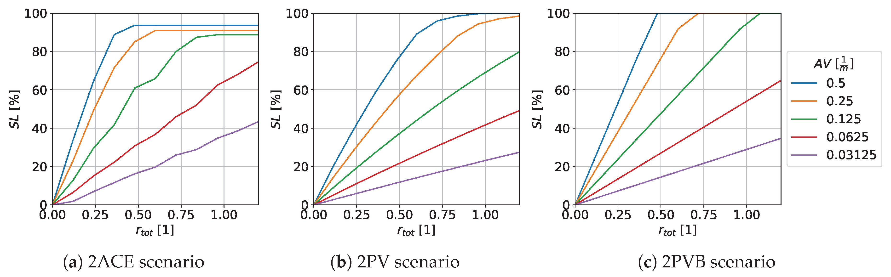
Table 1.
Total daily electricity consumption of the reference scenario for different energy efficiency ratios .
Table 1.
Total daily electricity consumption of the reference scenario for different energy efficiency ratios .
| eer / [1] | 1.50 | 2.00 | 2.50 | 3.00 | 3.50 |
| / | 43.87 | 33.68 | 27.55 | 23.45 | 20.50 |
Table 2.
Total daily electricity consumption of the reference scenario for different façade area to room volume ratios .
Table 2.
Total daily electricity consumption of the reference scenario for different façade area to room volume ratios .
| AV / | 0.50 | 0.25 | 0.12 | 0.06 | 0.03 |
| b / | 8 | 16 | 32 | 64 | 128 |
| / | 96 | 192 | 384 | 768 | 1536 |
| / | 64 | 256 | 1024 | 4096 | 16384 |
| / | 9.90 | 27.56 | 88.30 | 311.72 | 1166.71 |
Disclaimer/Publisher’s Note: The statements, opinions and data contained in all publications are solely those of the individual author(s) and contributor(s) and not of MDPI and/or the editor(s). MDPI and/or the editor(s) disclaim responsibility for any injury to people or property resulting from any ideas, methods, instructions or products referred to in the content. |
© 2026 by the authors. Licensee MDPI, Basel, Switzerland. This article is an open access article distributed under the terms and conditions of the Creative Commons Attribution (CC BY) license (http://creativecommons.org/licenses/by/4.0/).
Copyright: This open access article is published under a Creative Commons CC BY 4.0 license, which permit the free download, distribution, and reuse, provided that the author and preprint are cited in any reuse.


