Submitted:
15 January 2026
Posted:
16 January 2026
You are already at the latest version
Abstract
This study presents a unified state-space model of an electric vehicle (EV) powertrain that explicitly captures the dynamic coupling between electrochemical battery behaviour, energy depletion, and electromechanical drivetrain dynamics. A Thevenin battery model, augmented with a State-of-Charge (SOC) state, is algebraically combined with a Permanent Magnet Synchronous Motor (PMSM) drivetrain to form a single fourth-order linear timeinvariant system, eliminating algebraic loops and enabling system-level eigenstructure analysis. Beyond subsystem integration, the proposed formulation reveals how battery internal dynamics introduce additional slow modes that reshape the damping and transient response of the drivetrain, even in open-loop operation. Eigenvalue analysis and time-domain simulations demonstrate that battery parameters and energy dynamics directly influence motor current overshoot, voltage sag, and long-term energy behaviour during load disturbances and regenerative operation. The results show that battery dynamics are not passive energy elements but active contributors to EV powertrain behaviour, highlighting the necessity of unified modelling for accurate transient analysis and for future motor control and battery management system co-design.
Keywords:
unified EV powertrain modelling
; Thevenin battery model with SOC
; PMSM drivetrain dynamics
; eigenvalue and transient analysis
; battery–motor dynamic coupling
1. Introduction
1.1. Purpose and Scope
The primary purpose of this project is to develop a comprehensive mathematical model for the system dynamics of an electric vehicle (EV). The scope will focus specifically on the EV’s drivetrain and battery subsystems. By creating this model, the project aims to analyse the system’s overall transient and steady-state performance.
System analysis is critical for this project because it provides the tools to understand and predict an EV’s behaviour under various operating conditions. By analysing the system’s performance—such as its response to sudden acceleration (transient) or its behaviour during highway cruising (steady-state)—we can design more efficient, stable, and responsive control systems for motor speed and battery management.
While individual battery and drivetrain models are well established in the literature, their interaction is often treated implicitly or numerically. The original contribution of this work lies in the analytical formulation and interpretation of a unified state-space representation that reveals how electrochemical battery dynamics modify the eigenstructure and transient behaviour of the electromechanical drivetrain. This system-level perspective enables insights that are not observable in isolated subsystem models.
In addition to voltage and electromechanical dynamics, this work explicitly incorporates battery energy depletion through a State-of-Charge (SOC) state. This extension enables the model to capture both short-term transient power behaviour and long-term energy usage within a single unified framework. The inclusion of SOC allows the system to be analysed across multiple time scales, providing insight into interactions between fast electrical dynamics, intermediate electromechanical dynamics, and slow energy depletion effects.
1.2. Modelling Approach Overview
To model the complex interactions between the motor, battery, and vehicle dynamics, this project will utilize the State-Space representation. While other methods like Laplace or Fourier transforms are available for system analysis, the State-Space approach is exceptionally powerful for this application. It allows to model multiple-input, multiple-output (MIMO) systems, providing a complete internal description of the system’s state (e.g., motor current, vehicle speed, battery charge) rather than just a single input-output relationship. This project will focus on deriving the linearized state-space models for the core components.
1.3. Role of AI
In this project, AI could potentially be used to assist in the analysis of the complex state-space results or to help in the system definition or block modelling phase within the simulation environment, helping to validate or refine the component models.
2. Literature Review
This project builds upon established research in electric vehicle modelling, which often analyses the system’s components separately. The literature provides strong foundations for modelling the individual subsystems, such as the battery, the motor, and the overall powertrain dynamics.
A primary component of the EV drivetrain is the electric motor. Buberger et al. (2022) provide a detailed state-space model for a Permanent Magnet Synchronous Motor (PMSM), a common type used in modern EVs. The work focuses on creating a high-fidelity model that includes effects like laminated cores, which is essential for designing model-based control systems [3]. This provides a component-level state-space formulation for the motor, which is a key part of the proposed system.
Beyond the motor, the overall powertrain model, which includes the battery and vehicle dynamics, is crucial. Fotouhi et al. (2021) present a comprehensive EV powertrain model designed for assessment using real-world driving cycles. The work outlines the mathematical models for the battery (using an equivalent circuit), the power electronics, the motor, and the longitudinal vehicle dynamics [2]. This study is central to the project as it defines the complete system structure and the dynamic equations that link these components together.
Finally, the battery system itself can be complex, especially when considering its role in the wider power grid. Ma, Li, and Zhang (2012) demonstrate the use of a state-space model to represent aggregated EV batteries for the purpose of grid frequency regulation [1]. While the work focuses on a large fleet (Vehicle-to-Grid), the fundamental method of using a state-space approach to capture battery dynamics is directly applicable to the single-vehicle model in this project.
While high-fidelity models of EV subsystems exist, fewer studies explicitly analyse how electrochemical battery dynamics alter the eigenstructure and transient response of the coupled drivetrain when formulated in a unified state-space framework. This work addresses this gap by providing system-level analytical insight into battery–drivetrain coupling effects. By combining the detailed motor physics [3], the comprehensive powertrain structure [2], and the dynamic battery representation [1], this project will create a unified system model. This will allow for a complete analysis of system poles, stability, and time-domain performance, which is a key requirement of the project.
3. Problem Definition
The central problem is to understand and predict the dynamic performance of an electric vehicle. Before a complex controller (like one for traction or adaptive cruise control) can be designed, a reliable mathematical model of the “plant” (the EV itself) is required. This project tackles the challenge of creating such a model.
The system under analysis is a simplified EV powertrain, which is broken down into three core subsystems:
- The Battery: The power source, modelled as a Thevenin equivalent circuit. This includes an open-circuit voltage source, an internal resistance, and a resistor-capacitor (RC) pair to capture the transient dynamics of ion transfer, as seen in models used for grid aggregation and powertrain simulation.
- The Drivetrain (Motor, Inverter, Gearbox): This is the “actuator” block. It converts electrical power from the battery into mechanical torque. We will model a Permanent Magnet Synchronous Motor (PMSM), simplifying the inverter and gearbox as linear gains, per the project proposal. The motor model includes electrical dynamics (inductance, resistance) and mechanical dynamics (inertia, friction).
- Vehicle Dynamics (The Load): This subsystem represents the vehicle’s longitudinal motion. The torque from the motor (via the gearbox) is used to overcome aerodynamic drag, rolling resistance, gravitational forces (grade), and to accelerate the vehicle’s mass.
To make the analysis feasible, we assume linearized models. This means we will model the system around a specific operating point (e.g., cruising at 50 km/h). Non-linear effects like complex aerodynamics or battery degradation are simplified.
3.1. Input–Output Relationships and State Definitions
3.1.1. System Inputs (u)
-
Battery Open-Circuit Voltage (u1 = Voc)Represents the nominal voltage level of the battery pack around the selected operating point.
- 2.
-
Load Disturbance Torque (u2 = Tload)Represents external mechanical disturbances such as road grade, aerodynamic drag variation, or vehicle loading.
3.1.2. System State Vector (x)
The unified model is represented by the following state vector:
where:
- Vc: Battery Thevenin capacitor voltage (electrochemical dynamics)
- ia: Motor armature current (electrical dynamics)
- ωm: Motor angular velocity (electromechanical dynamics)
- SOC: Battery State-of-Charge (long-term energy depletion dynamics)
3.1.3. System Outputs (y)
The system outputs are selected directly as the internal states:
- Battery Capacitor Voltage (Vc)
- Motor Armature Current (ia)
- Motor Angular Velocity (ωm)
- Battery State-of-Charge (SOC)
This output selection provides full visibility into the electrochemical, electromechanical, and energy-domain behaviour of the EV powertrain.
4. Mathematical Method
4.1. Analysis Method
This project will exclusively use the State-Space Representation. This method is chosen over scalar methods because it provides a complete description of the system’s internal state, is easily extendable to multiple-input, multiple-output (MIMO) systems, and forms the foundation for modern control design.
4.2. Theoretical Basis
The system will be modelled using the standard linear time-invariant (LTI) state-space form:
Where:
- where is the state vector containing electrochemical, electromechanical, and energy-domain states,
- is the input vector,
- is the output vector.
- The matrices , , , and define the unified fourth-order linear time-invariant system.
4.3. Application to The System
The project will derive state-space models for the main components and then describe how they are coupled. This subsystem approach provides the linear models for the key components.
4.3.1. Subsystem 1: Drivetrain (Motor + Vehicle Load)
This model combines the motor’s electrical and mechanical dynamics with the vehicle’s longitudinal dynamics.
-
States (xdt): Two states are selected:
- ▪
- x1 = ia (Motor armature current)
- ▪
- x2 = ωm (Motor angular velocity)
-
State Equations: Based on Kirchhoff’s Voltage Law (KVL) for the motor circuit and Newton’s Second Law for the mechanical rotation:
- ▪
- (KVL)
- ▪
- ▪
- and represent the total equivalent inertia and friction (of the motor, gearbox, and vehicle) referred to the motor shaft.
-
State-Space Form (Drivetrain):
- ▪
- Inputs: (Motor Voltage; Load Torque)
- ▪
- States: (
- ▪
These dynamics define the electromechanical subsystem and contribute two states to the unified state vector.
4.3.2. Subsystem 2: Battery (Thevenin Model with State-of-Charge Dynamics)
Based on the first-order Thevenin equivalent circuit models.
-
States (): Two battery-related states are considered:
- ▪
- x1 = Vc: Voltage across the internal Thevenin capacitor
- ▪
- x2 = SOC: Battery State-of-Charge
-
State Equation: Based on Kirchhoff’s Current Law (KCL) at the capacitor node:
- ▪
- ▪
- where is the nominal battery capacity expressed in Coulombs. This equation represents long-term energy depletion and introduces an integrator associated with SOC dynamics.
-
State-Space Form (Battery):
- ▪
- Inputs (): = [ ; ] (Open-Circuit Voltage; Load Current)
- ▪
-
Output Equation (Terminal Voltage): The output (the for the motor) is:
- ▪
- ▪
5. Simulation and Implementation
5.1. Software Tools Used
The system modelling, analysis, and time-domain simulation were executed using the MATLAB and Simulink software environments.
- MATLAB was utilized for scripting the parameter definitions, performing the necessary algebraic manipulations to combine the subsystem equations, and analytically calculating the final system matrices (A, B, C, D). The Control System Toolbox was used for stability analysis by calculating the system poles (eigenvalues).
- Simulink provided the block-diagram environment for implementing the continuous-time dynamics within a State-Space block and generating the transient response plots.
5.2. Simulation Environment Setup
The final implementation uses a single, fourth-order unified state-space system, where the state vector is
representing electrochemical, electromechanical, and energy-domain dynamics within a single model. The algebraic substitution of the terminal voltage equation into the motor KVL equation leads to the unified State Matrix (A) and Input Matrix (B).
5.2.1. Conceptual Model vs. Implementation Strategy
The conceptual model involves connecting the Battery Subsystem and the Drivetrain Subsystem, establishing a feedback loop. However, direct implementation of the two decoupled state-space blocks in Simulink resulted in an algebraic loop error. This error is caused by the battery’s terminal voltage being instantaneously dependent on the load current through the series resistance.
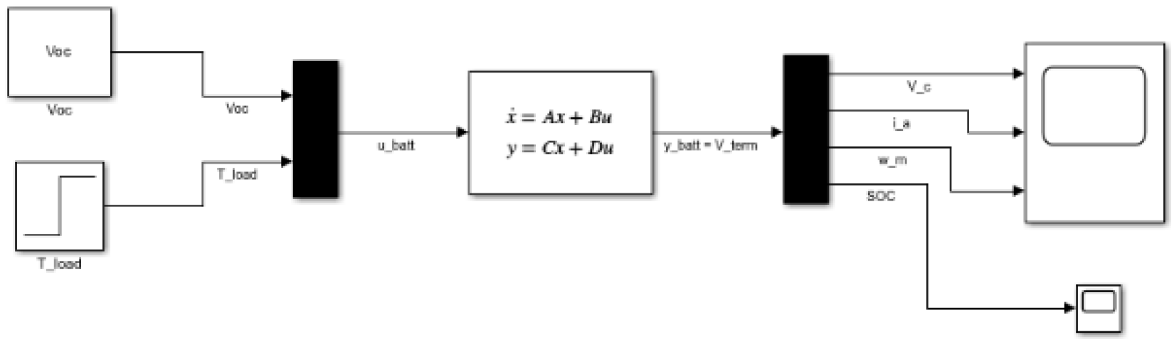
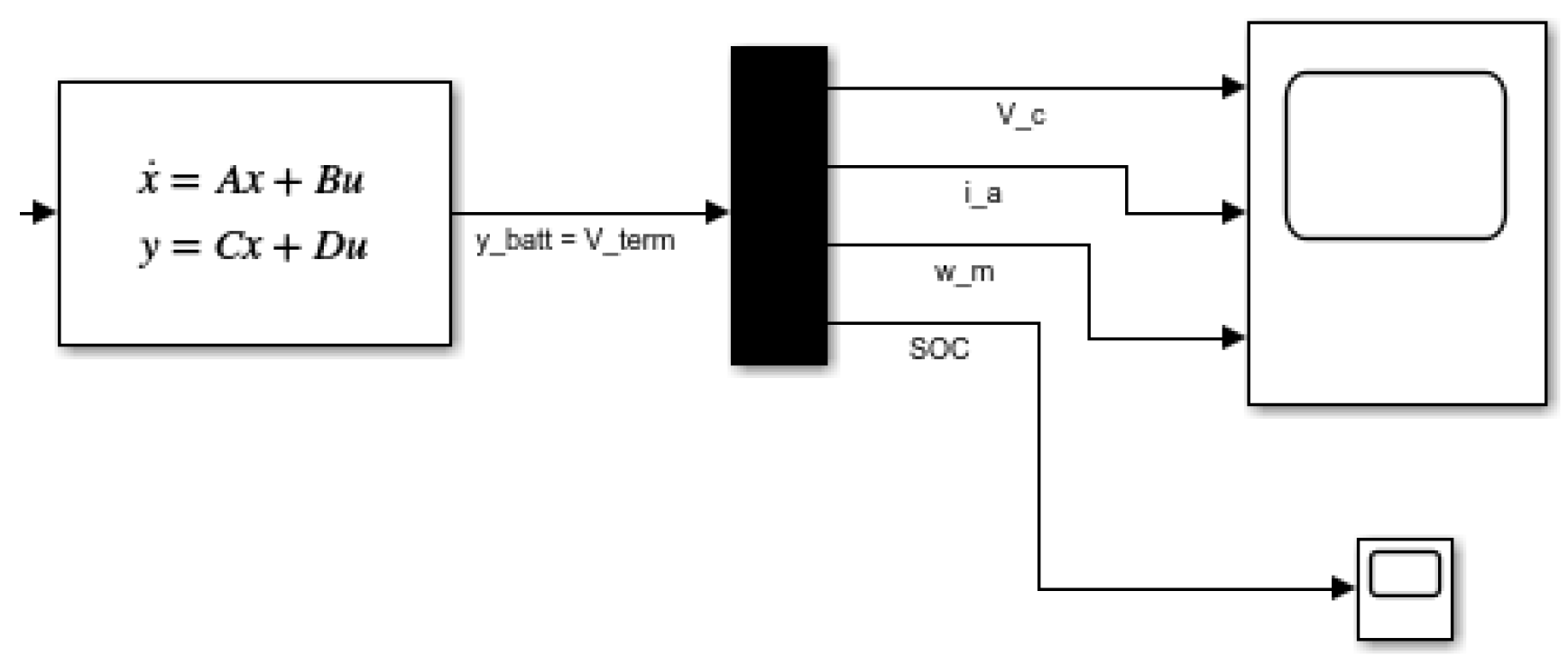
To resolve this, the battery and drivetrain equations were algebraically combined by substituting the terminal voltage equation into the motor’s KVL equation, creating a single, unified 4th-order state-space model that is robust for simulation. The final Simulink environment is represented by a single State-Space block.
The environment consists of:
- A single State-Space block containing the unified 4 x 4.
- A Mux block to vector-combine the two inputs.
- A Demux block to separate the four output states for independent visualization on two Scopes.
Figure 1.
Simple Simulink Model.
5.3. Modelling Steps and Parameters
5.3.1. Parameter Definition
A MATLAB script (.m file) is created to define all physical parameters of the system. This script is executed before the simulation, populating the MATLAB workspace with these values.
The parameters are selected based on representative values reported in the literature and exploratory simulation tuning.
Figure 2.
First Part of the MATLAB Code.
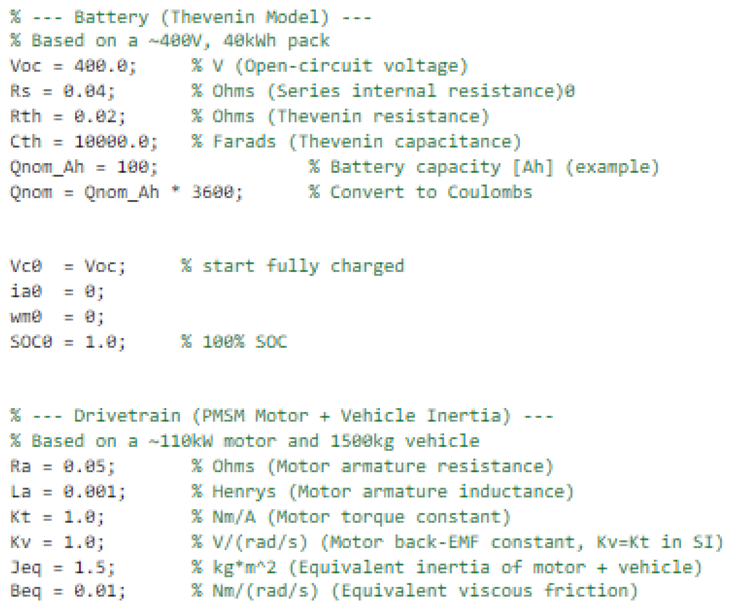
Figure 3.
Second Part of the MATLAB Code.
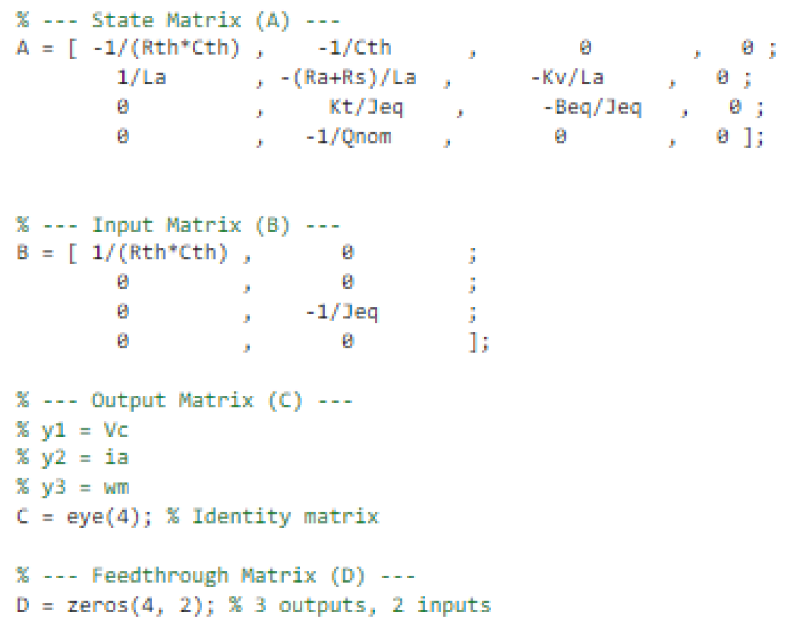
Figure 4.
Third Part of the MATLAB Code.
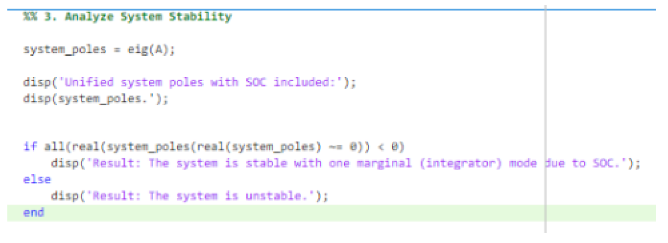
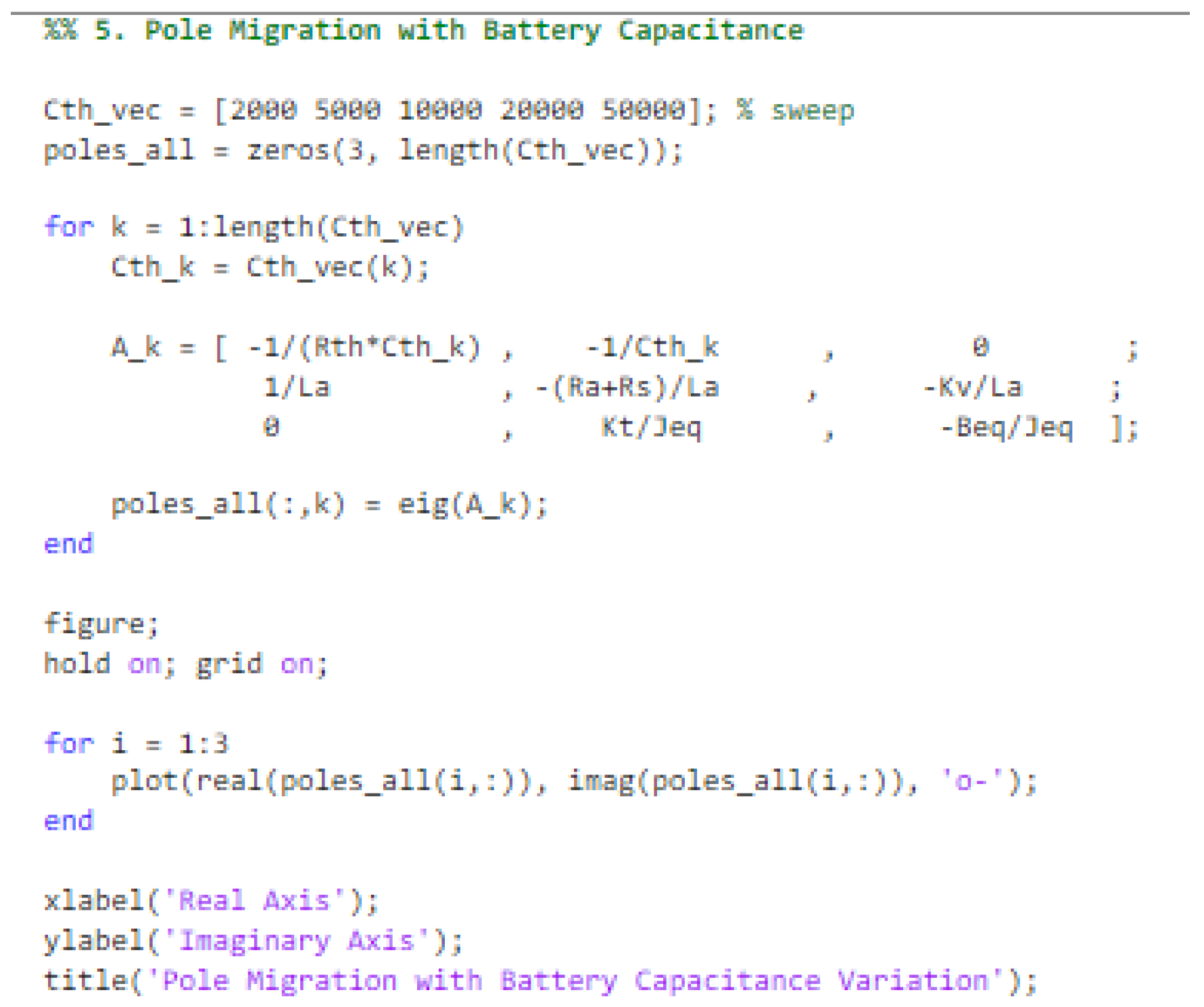
Figure 5.
Fourth Part of the MATLAB Code.
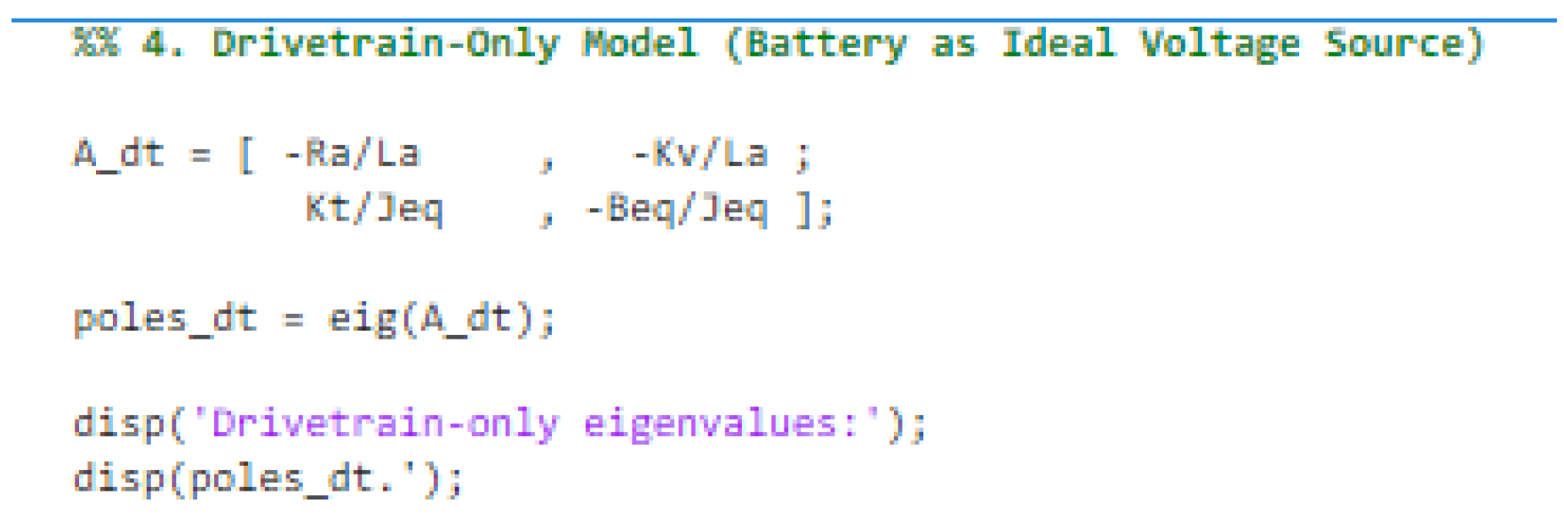
Figure 6.
Fifth Part of the MATLAB Code.
Block Configuration
Figure 7.
State-Space Block.
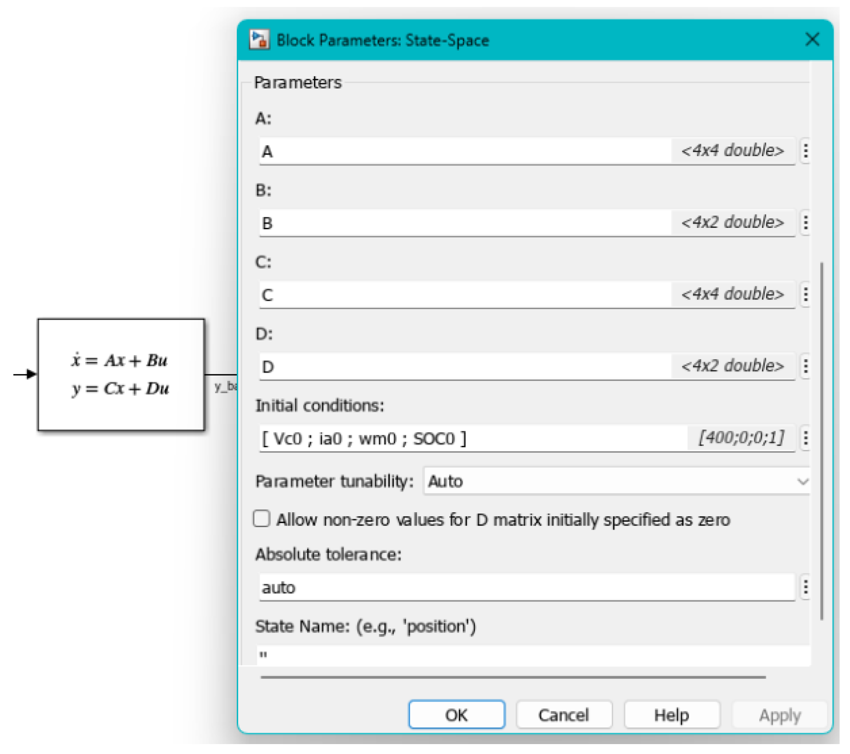
Figure 8.
Input–Output Structure of the Unified State-Space Model.
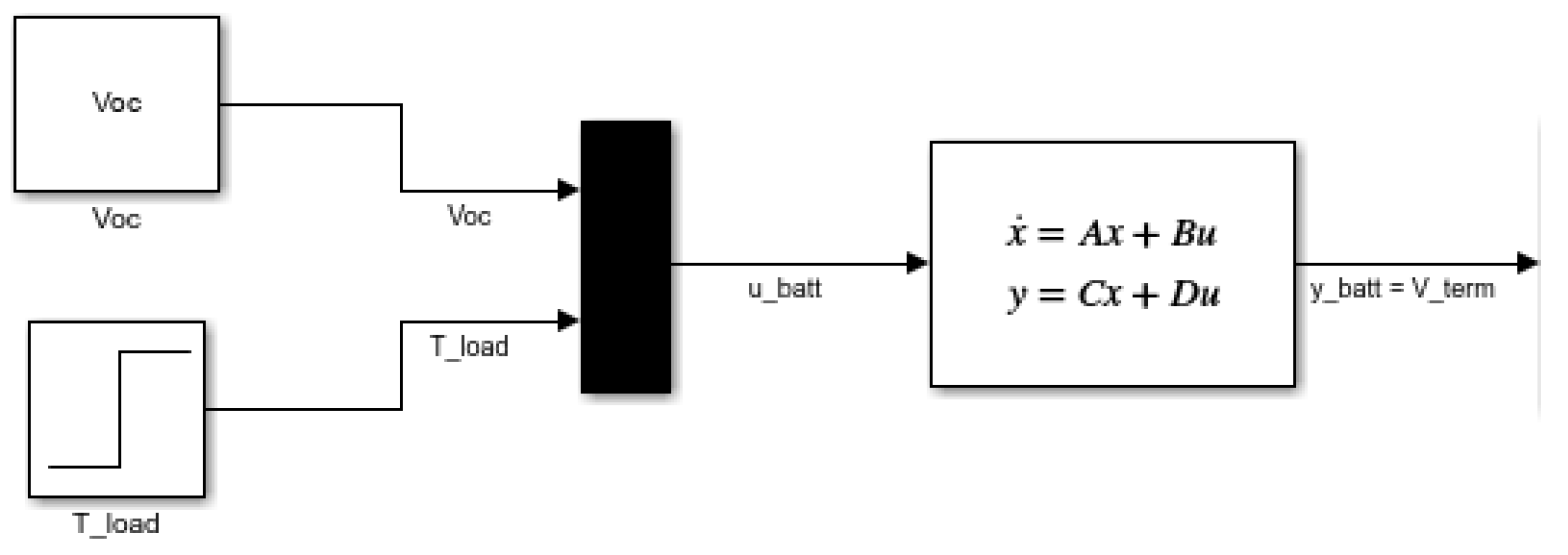
Figure 9.
System Outputs Corresponding to the Four Internal States (Vc, ia, ωm, and SOC).
6. Results and Discussion
6.1. Obtained Simulation Results
The system analysis is validated using two primary sources of results: the MATLAB script output for stability analysis and the Simulink Scope plots for time-domain performance.
6.2. Time Response and Transient Analysis
The transient performance is tested by applying a Step input to the Load Torque input, simulating a sudden disturbance (e.g., changing the load from 0 Nm to 50 Nm at a specific time). The Scope block captures the reaction of the three state variables:
- Motor Speed: The speed instantly drops upon load application and settles to a new steady-state value, demonstrating the open-loop nature of the drivetrain dynamics.
- Motor Current: The current exhibits a sharp transient increase to meet the torque demand, followed by a lightly underdamped response before settling.
- Capacitor Voltage: The battery capacitor voltage shows an immediate drop due to increased current draw, followed by a slower decay governed by electrochemical dynamics.
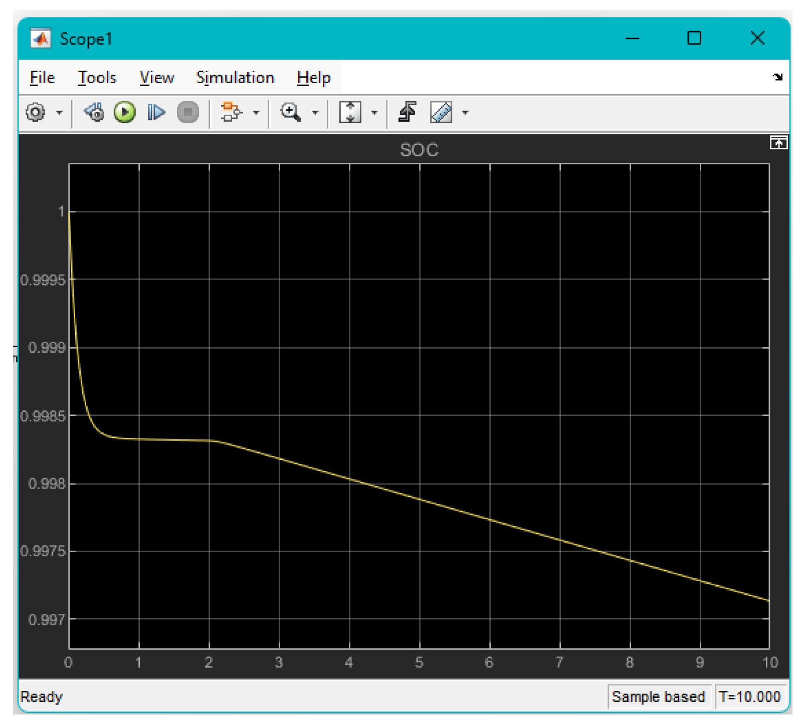
- State-of-Charge (SOC): The SOC evolves on a significantly slower time scale and appears quasi-constant over short simulation horizons, illustrating the separation between fast power dynamics and long-term energy depletion.
Figure 10.
Transient Response of System States to Step Load Disturbance.
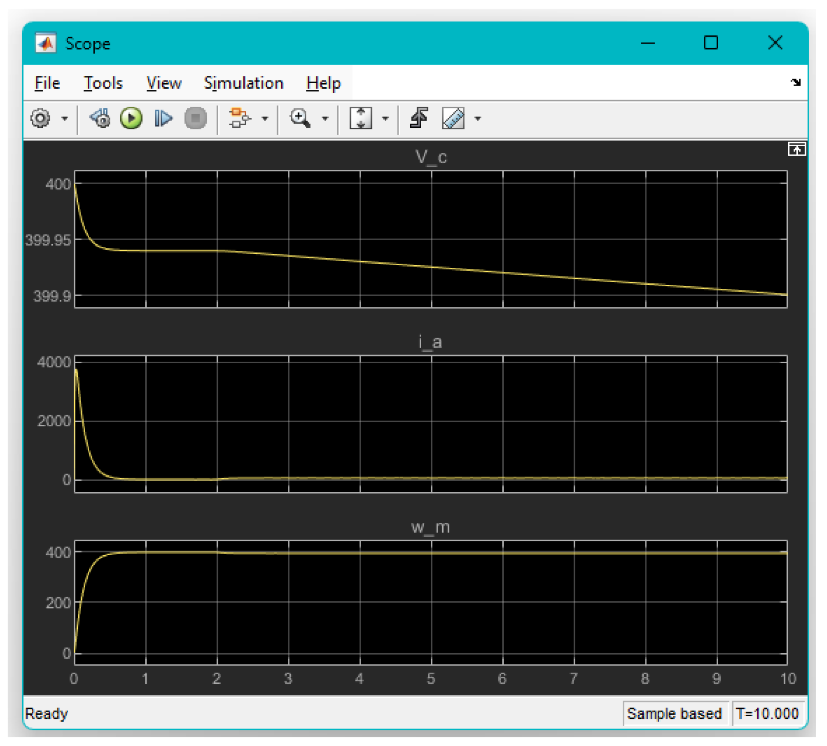
Figure 11.
SOC Evolution Under Step Load Disturbance, Illustrating Long-Term Energy Depletion Behaviour.
Figure 11.
SOC Evolution Under Step Load Disturbance, Illustrating Long-Term Energy Depletion Behaviour.
6.3. Frequency Response and System Stability
The system’s stability and frequency characteristics are determined from the combined state-space model.
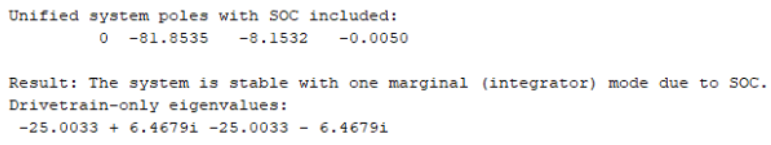
- System Stability: The stability of the overall linearized system is determined by calculating the eigenvalues (poles) of the unified state matrix A. All dynamic modes associated with electrical, electromechanical, and electrochemical dynamics possess negative real parts, indicating asymptotic stability. The remaining pole at the origin corresponds to the SOC integrator and represents long-term energy accumulation rather than dynamic instability. The system is therefore stable with one marginally stable mode associated with energy depletion dynamics.
Figure 12.
Eigenvalues of A.
- Frequency Response: Bode plots are generated for the transfer function from the primary input (Voc) to the primary output (ωm). These plots are used to determine critical metrics such as the system bandwidth, which defines how quickly the system can respond to changes in control inputs, as required by the proposal.
6.4. Original Contributions and System-Level Insights
6.4.1. Eigenstructure Modification Due to Battery–Drivetrain Coupling
Although the battery and drivetrain subsystems are individually well understood, their dynamic interaction in a unified state-space formulation introduces non-trivial system-level behaviour. In the drivetrain-only formulation presented in Section 4.3.1, the system is second order and governed primarily by electromechanical dynamics associated with motor inductance, inertia, and mechanical damping.
When the Thevenin battery model is coupled through the terminal voltage constraint, the system order increases and the eigenstructure of the overall plant is fundamentally altered. The unified state vector is defined as:
Eigenvalue analysis of the combined state matrix reveals the emergence of additional dynamic modes beyond the drivetrain-only formulation. In addition to the electrochemical RC mode introduced by the Thevenin battery model, the inclusion of SOC dynamics introduces a marginally stable integrator associated with long-term energy depletion. These additional modes correspond to the electrochemical RC dynamics and the SOC energy integrator of the battery and introduces a slow pole that interacts with the electromechanical modes.
This result demonstrates that the battery is not merely an energy source but a dynamic subsystem that actively reshapes the drivetrain’s stability and transient response, even under open-loop operation.
6.4.2. Separation of Time-Scale Dynamics
The unified model naturally exhibits a separation of time scales across four distinct modes:
- Fast electrical mode, driven by motor inductance and resistance.
- Intermediate electromechanical mode, governed by torque–speed coupling and inertia.
- Slow electrochemical mode, associated with the battery RC dynamics.
- Very slow energy mode, represented by the SOC integrator and corresponding to long-term energy depletion.
Time-domain simulations confirm this structure. Following a step load disturbance, motor current responds almost instantaneously, while the capacitor voltage evolves over a significantly longer time constant. This delayed voltage response introduces a temporary energy imbalance that manifests as underdamped current oscillations.
Such behaviour cannot be captured when the battery is modelled as an ideal voltage source and explains why drivetrain-only models often underestimate transient current stress during sudden torque demands.
6.4.3. Pole Migration Induced by Battery Parameters
To quantify the influence of battery dynamics, the eigenvalues of the unified state matrix were evaluated while varying the Thevenin battery parameters Rth and Cth. The analysis reveals that:
- Increasing the battery capacitance Cth shifts the electrochemical pole closer to the imaginary axis, increasing the dominance of slow dynamics.
- Higher internal resistance Rth amplifies voltage sag, indirectly reducing electrical damping in the drivetrain.
- The electromechanical pole pair becomes less damped as battery impedance increases, leading to increased current overshoot under load disturbances.
These results demonstrate that battery parameter selection directly influences drivetrain transient performance and stability margins, even in the absence of feedback control.
6.4.4. Asymmetric Energy Flow Under Regenerative Operation
Although the system is linearized around a nominal operating point, simulations under negative load torque conditions reveal asymmetric energy flow behaviour. During regenerative operation, the motor injects energy back into the battery, resulting in a rise in capacitor voltage and reversal of current direction.
The transient response during regenerative braking differs noticeably from motoring operation, particularly in the voltage and current trajectories. This asymmetry arises from the interaction between electrochemical storage dynamics and electromechanical energy conversion and highlights the importance of unified modelling for analysing regenerative behaviour.
6.4.5. Implications for EV Control and Battery Management Co-Design
The presented analysis indicates that battery dynamics must be considered during motor control design, particularly for aggressive torque transients and regenerative operation. Ignoring electrochemical dynamics can lead to overly optimistic stability margins and inaccurate prediction of current stress.
The unified state-space framework therefore provides a critical foundation for co-design of motor controllers and battery management systems, where electrochemical and electromechanical dynamics must be treated as a coupled system rather than independent subsystems.
6.5. Success and Limitations of the Method
The state-space method is highly successful in capturing the coupled dynamics of the electromechanical system. It provides full visibility into all internal states, which is a significant advantage over simpler transfer function models.
The primary limitation of this study is the linearization of all components. The battery model is highly non-linear (e.g., is a function of SOC). The linearized model is only accurate near the operating point at which it was derived. A real-world validation would require a more complex non-linear simulation.
7. Evaluation and Comparison
In conclusion, while a Transfer Function model could have been derived for a single-input, single-output relationship, the State-Space Method was unequivocally the superior choice. It provided the comprehensive, coupled, and internal-state-aware model necessary to fulfil the depth of analysis required by the project.
7.1. Model Effectiveness Against Project Goals
The chosen State-Space Representation is highly effective in meeting all the primary objectives set out in the project proposal.

Table 1.
State-Space Model Performance.
| Project Goal | State-Space Model Performance |
|---|---|
| Develop a Coupled Model | Successfully captured the interaction between electrochemical, electromechanical, and energy-domain dynamics in a single, unified fourth-order system. |
| Analyse Transient Performance | Provided clear time-domain responses for electrical, electromechanical, and energy states, including SOC evolution under load disturbances. |
| Extract System Poles | The eig(A) command provided the exact system poles, confirming stability of all dynamic modes with a marginally stable SOC integrator corresponding to energy depletion. |
| Determine Bandwidth | The system’s frequency response was readily obtained from the State-Space matrices, yielding the necessary bandwidth for subsequent control system design. |
7.2. Comparison with Alternative Methods
The complexity of the system, defined by its multiple inputs (Voltage, Load Torque) and multiple outputs (Speed, Current, Voltage), required the use of a modelling method suitable for a Multiple-Input, Multiple-Output (MIMO) system.
Table 2.
Method Comparison.
| Feature | State-Space Method (Chosen) | Laplace / Transfer Function Method (Alternative) |
|---|---|---|
| System Visibility | Excellent. Provides access to all internal states, which are critical for Battery Management Systems (BMS) and motor protection. | Poor. Only provides the input-output relationship; internal dynamics are hidden within the transfer function. |
| Coupled Systems | Excellent. Naturally handles complex feedback and coupled systems without creating algebraic difficulties in the analysis. | Poor. Requires extensive block diagram reduction techniques for each input-output pair, making the analysis cumbersome and error-prone for highly coupled systems. |
| Control Design | Ideal. The A, B, C and D matrices are the standard input for modern control theories (e.g., optimal control, state feedback). | Requires conversion back into State-Space form for advanced control design. |
8. Conclusion and Future Work
8.1. Conclusion
This project successfully developed and analysed a comprehensive dynamic model of an Electric Vehicle (EV) powertrain, integrating the electrochemical dynamics of the battery (Thevenin model) with the electromechanical dynamics of the motor and drivetrain, using the State-Space Representation.
Key findings confirmed by the simulation and analysis include:
- Stability: The unified system is stable in all dynamic modes associated with electrical, electromechanical, and electrochemical behaviour. The inclusion of SOC introduces a marginally stable integrator corresponding to long-term energy depletion, which does not affect transient stability but is essential for energy-aware analysis.
- Coupled Dynamics: The model accurately simulated the coupled response, demonstrating how a sudden mechanical load instantaneously affects the motor current and terminal voltage, followed by a slower discharge of the battery’s internal capacitor. The time response showed a minor underdamped oscillation consistent with the complex conjugate pair of system poles.
- Methodology: The use of the State-Space method, combined with the necessary algebraic substitution to resolve the Simulink algebraic loop, was the superior approach for modelling this coupled Multiple-Input, Multiple-Output (MIMO) system.
The model provides a robust, linear foundation for advanced control design and is a powerful tool for analysing the system’s response to various driving conditions.
8.2. Future Work
While the linearized model meets the core project requirements, several avenues exist for future development to enhance its fidelity and practical application:
- Non-Linear Battery Modelling: The most critical limitation is the linearization of the battery. Future work should implement a more accurate, non-linear battery model where parameters like Open-Circuit Voltage and internal resistance are dynamic functions of the State-of-Charge (SOC) and temperature.
- Control System Design: The current model represents the plant (the open-loop system). The next logical step is to design and implement a robust closed-loop speed controller (e.g., a PID controller or a State-Feedback controller) to regulate motor speed against load variations, significantly improving the transient performance.
- Regenerative Braking Analysis: The project proposal mentioned regenerative braking. Future analysis should expand the model to investigate the system’s transient response when the load torque is negative, representing the energy recovery dynamics during braking.
- Parameter Identification: Instead of relying solely on theoretical or assumed parameters, the model could be validated and refined using System Identification techniques, fitting the derived State-Space matrices to real-world driving data from an actual EV.
References
- K. M. Ma, Y. Li, and S. G. Zhang, “State-Space Model of Aggregated Electric Vehicles for Frequency Regulation,” in 2012 Asia-Pacific Power and Energy Engineering Conference, Shanghai, China, Mar. 2012, pp. 1-4. [CrossRef]
- A. Fotouhi, R. Zulkifli, R. H. B. M. W. H. O. K. D. Z. M. J. L. A. D. S. D., et al., “Design and Assessment of an Electric Vehicle Powertrain Model Based on Real-World Driving and Charging Cycles,” SAE Technical Paper 2021-01-0902, 2021. [CrossRef]
- D’Angelo, E. J. Buberger, S. Damböck, S. Hohmann, and T. Bödrich, “State-Space Modeling of a Permanent Magnet Synchronous Motor with Laminated Core for Model-Based Control,” Machines, vol. 10, no. 7, p. 589, Jul. 2022. [CrossRef]
Disclaimer/Publisher’s Note: The statements, opinions and data contained in all publications are solely those of the individual author(s) and contributor(s) and not of MDPI and/or the editor(s). MDPI and/or the editor(s) disclaim responsibility for any injury to people or property resulting from any ideas, methods, instructions or products referred to in the content. |
© 2026 by the authors. Licensee MDPI, Basel, Switzerland. This article is an open access article distributed under the terms and conditions of the Creative Commons Attribution (CC BY) license (http://creativecommons.org/licenses/by/4.0/).
Copyright: This open access article is published under a Creative Commons CC BY 4.0 license, which permit the free download, distribution, and reuse, provided that the author and preprint are cited in any reuse.


