
Submitted:
14 January 2026
Posted:
15 January 2026
You are already at the latest version
Abstract
To mitigate structural vibrations caused by liquid sloshing inside the suspended water tank of high-speed trains and to prevent issues such as baffle fatigue failure and water leakage from tank cracking, this study designed an acoustic black hole (ABH)-type baffle that comprehensively considers both vibration and wave suppression performance. Based on acoustic black hole (ABH) theory, numerical simulations were conducted using the CFD software Fluent to analyze the vibration and wave suppression characteristics of the ABH-type baffle under lateral and longitudinal impact conditions. The influence of the position and number of ABH structures on the baffle’s performance was systematically examined. Finally, the structural strength and the vibration/wave suppression capability of the baffle were validated.The results demonstrate that the structural strength of the ABH-type baffle meets the design requirements. Compared to a conventional baffle, the ABH-type baffle reduces the liquid sloshing force inside the tank, lowers the peak sloshing pressure under various operating conditions, and decreases the surface vibration velocity of the baffle within its dominant vibration frequency range of 0–100 Hz. The optimal positions for the ABHs are at the 80% and 20% water-level lines on the baffle, and the best suppression performance is achieved when the center of the ABH is aligned horizontally with the liquid surface. Furthermore, the vibration and wave suppression capability deteriorates when the number of ABHs is either greater or fewer than three.
Keywords:
high-speed train suspended water tank
; CFD
; acoustic black hole-type baffle
; vibration suppression characteristics
; sloshing suppression characteristics
; structural design
1. Introduction
High-speed trains represent a vital force for achieving regional sustainable development [1,2]. The water supply system of high-speed trains is responsible for functions such as restroom water supply, drinking water provision, and carriage air conditioning cooling. Its normal operation relies on suspended water tank equipment providing a stable and continuous water source. However, frequent acceleration and braking during high-speed train operation induce nonlinear liquid sloshing, which can impose repeated dynamic impacts on the water tank, generating sustained structural vibration [3,4]. This exacerbates the cumulative fatigue damage at the connection points between the built-in baffle and the external car body with the water tank, potentially leading to issues such as fatigue failure of the baffle, tank cracking, and water leakage [5,6,7], which may compromise the safe operation of high-speed trains.
Installing internal baffles is an important method for suppressing liquid sloshing within the tank and mitigating tank structural vibration. Recent related research has found that the intensity of liquid sloshing in water tanks is related to the number, type, and structural design of the baffles themselves [8,9,10]. In studies on the influence of baffle quantity on tank structural vibration and liquid sloshing, Lu and Cao [11] investigated the effect of the number of vertical baffles in a rectangular tank on liquid sloshing, using the SPH method for numerical simulation. They demonstrated that increasing the number of baffles can reduce the system’s natural frequency, enhance damping energy dissipation, and reduce wave height and dynamic pressure. In research on the influence of baffle orientation, Amirsardari et al. [12], through experiments and numerical simulation, confirmed that vertical baffles can significantly reduce the hydrodynamic pressure (20%-70%) and base shear force (9%-65%) in tanks under seismic conditions. The optimal effect was achieved when the baffle height-to-water depth ratio was 0.75, providing a reference for tank seismic design. Furthermore, tangential baffles in cylindrical storage tanks outperform radial baffles, achieving a damping ratio up to twice that of radial baffles, significantly reducing the system’s natural frequency, and generating new multi-peak waves to attenuate liquid surface height [13]. Research on the influence of baffle shape found that tree-shaped baffles, through their branching structure, enhance energy dissipation. Under 50% fill ratio and resonance conditions, they can reduce the maximum wall force by 36.3% and wave height by 28.1% [14]; sinusoidal, cosine-shaped, and their straight-edge variant baffles can effectively reduce the natural frequency at low fill depths, achieving a damping ratio 10-12 times that of a tank without baffles at a dimensionless depth of 1.15 [15]. Studies on baffle opening shapes indicate that their influence on liquid sloshing suppression in rectangular tanks is not significant, but perforated baffles can effectively suppress first-order resonance, achieving an 85% suppression rate for side wall wave amplitude, although their suppression effect on third-order resonance is weaker [16]. Additionally, baffle installation parameters are crucial. When placed 80 mm from the initial liquid surface, the free surface height can be reduced to 6.39 mm. Baffles with a 30° inclination angle can counteract dynamic impact through fluid collision, reducing turbulent energy [17]. Although existing research has analyzed the effects of baffle quantity [11], orientation [12,13], shape [14,15], opening form [16], and installation parameters [17] on structural vibration and liquid sloshing in various tanks, the mechanism of how the liquid surface evolution mechanism under impact in high-speed train suspended water tanks affects baffle structural response remains unclear. With China’s ongoing promotion of green innovation guided by the “dual carbon goals,” the operational speed of new high-speed trains continues to increase [18]. During train start-up and braking states, especially under emergency braking with increasingly higher accelerations, the sloshing impact force generated by the liquid inside suspended water tanks becomes stronger, leading to significantly larger deformation and vibration of the tank inner walls and baffles [19]. This poses new challenges to the performance and strength of existing baffle structures. Therefore, to adapt to the increasingly large impact loads on suspended water tanks, it is necessary to develop baffles with stronger vibration and sloshing suppression capabilities based on train lightweighting.
With the continuous development of structural mechanics and simulation technology, novel wave and vibration suppression structures have emerged. The acoustic black hole is a new wave control technique that focuses flexural waves through geometric parameter or material property variations. Under ideal conditions, the flexural wave speed gradually decreases to zero within the ABH region. The most obvious geometric feature of an ABH is a power-law varying cross-section [20], where the power exponent is at least 2, described by the shape function h(x)=εx^m(m≥2). Early research explored the flexural wave focusing effect of one-dimensional and two-dimensional ABHs through vibration response experiments [21,22]. Due to advantages such as simple structure, wide frequency range for vibration reduction, and high control efficiency, ABHs have found applications in vibration and noise control fields [23,24]. Bowyer et al.[25] embedded two-dimensional ABHs into automobile engine covers, effectively reducing the vibration amplitude of the covers and suppressing noise. Furthermore, related studies found that ABH damping structures with added mass could also effectively suppress structural vibrations in the 10–1000 Hz frequency range even when the mass was reduced by 30% [26]. The broadband performance of ABHs is comparable to active vibration control systems based on constant-thickness beams, but ABHs offer lower control costs and significant practical value [27].
Based on the above research background, to enhance the vibration and wave suppression performance of the suspended water tank baffle in high-speed trains and prevent issues such as fatigue failure of the baffle and water leakage due to tank cracking, this paper designs an ABH-type baffle structure for the suspended water tank of high-speed trains. The design is based on acoustic black hole theory and validated through numerical simulations conducted using the CFD software Fluent. The specific chapter arrangement is as follows: The first part completes mesh generation for the suspended water tank model, boundary condition setup in CFD software, and validation of numerical methods. The second part presents the analysis of experimental results. Firstly, multiple sets of comparative experiments are designed to analyze the liquid surface evolution mechanism under different liquid volumes, determining the flow field characteristic values required for subsequent research. Secondly, a three-factor, three-level orthogonal experiment is set up to determine the optimal parameters for a single ABH embedded in the baffle. The vibration and sloshing suppression effect of a single ABH is then verified. Building on this, the optimal parameters for the ABH-type baffle are analyzed from two dimensions: ABH position and quantity. Finally, multiple sets of comparative experiments are set up to verify the performance improvement of the ABH-type baffle compared to traditional baffles. The fourth part summarizes the conclusions of the entire paper and discusses the limitations of the study.
2. Model and Method
The Materials and Methods should be described with sufficient details to allow others to replicate and build on the published results. Please note that the publication of your manuscript implicates that you must make all materials, data, computer code, and protocols associated with the publication available to readers. Please disclose at the submission stage any restrictions on the availability of materials or information. New methods and protocols should be described in detail while well-established methods can be briefly described and appropriately cited.
2.1. Model and Mesh Generation
The CR 450 EMU (Fuxing CR 450 EMU Train) is a new generation of high-speed train developed by China State Railway Group Co., Ltd., aiming for commercial operation at 400 km/h, featuring higher safety, environmental protection, energy efficiency, and intelligence [28]. The effective capacity of the underframe suspended water tank on the CR 450 BF EMU is 700 L, which is 3.5 times the 200 L effective capacity of suspended water tanks on other CRH series trains [3]. This makes the liquid sloshing force under impact more significant for this tank type. The model of the underframe suspended water tank on the CR 450 BF EMU is shown in Figure 1a, mainly consisting of the tank body, baffles, underframe water pump device, underframe water pump electrical control box, external water system, antifreeze device, and suspension brackets. The internal fluid domain structure of the tank is shown in Figure 1b. The fluid domain is 2350.8 mm long, 585 mm wide, and 675 mm high. The internal baffle is vertically installed inside the tank, with height and width both 675 mm and 585 mm, and a thickness of 3 mm.
According to the requirements of TB/T 1720---2017 “Water Supply Equipment for Railway Passenger Cars and EMUs,” the suspended water tank structure is primarily welded from Q345 steel plates. The material physical property parameters are listed in Table 1.
This study adopts a bidirectional fluid-structure interaction (FSI) research method, with a unstructured tetrahedral mesh generation strategy. Due to the overall structural complexity of the suspended water tank, to reduce subsequent computational scale, certain components and irregular shapes are simplified while ensuring computational accuracy, thereby improving computational efficiency. To ensure result precision, the following simplifications are made during mesh generation:
- 1)
- Minor components such as tank water filling holes, overflow holes, cleaning holes, as well as external water pumps, pipes, switches, etc., unrelated to the internal fluid domain, have minimal impact on internal liquid flow and are therefore omitted;
- 2)
- Minor details such as small fillets and rounds that have little impact on structural strength and stiffness are ignored to improve mesh quality and avoid affecting simulation accuracy.
Mesh independence verification is a crucial step to ensure that calculation results are not affected by mesh generation [29]. Taking the boundary condition of the tank structure under static hydraulic pressure from a full tank and gravity as an example, with the top fixing structure subjected to fixed constraints. The relationship between mesh number and the pressure value on the tank bottom surface is shown in Table 2.
As the element size decreased from 10 mm to 9 mm, the pressure value refined from 3372.4 N to 3330.3 N, indicating that coarser meshes cannot sufficiently capture structural details, resulting in significant errors. When the element size is 8 mm, the error between the pressure value and the next level is only 0.11%, indicating that the calculation results tend to stabilize and are no longer affected by mesh count. When the mesh size is 7 mm, the fluid domain mesh count increases by 140%, which would significantly increase computation time. Therefore, considering time cost and solution efficiency comprehensively, this paper uses a 8 mm mesh for dividing both the solid and fluid domains of the suspended water tank. The mesh generation result is shown in Figure 2.
2.2. Boundary Conditions and Method
The unidirectional FSI method cannot obtain the time-varying stress distribution of the tank body nor consider the influence of solid structural deformation on the flow field. Therefore, this paper adopts a bidirectional FSI method, with the process shown in Figure 3. The research uses ANSYS Workbench to simulate the bidirectional interaction between fluid and structure. Its core principle lies in fluid loads acting on solid boundaries causing deformation or motion, while the deformation/motion of the solid in turn changes the geometry and boundary conditions of the fluid domain, thereby affecting the flow field distribution. Finite element calculations iterate within each time step: the fluid solver calculates loads -> transfers them to the structure solver -> the structure solver calculates deformation/displacement -> updates the fluid mesh -> the fluid solver recalculates the flow field based on the new geometry, until the coupled solution for that time step converges. This method can effectively simulate the mechanical response behavior of the baffle during high-speed train operation when a certain amount of liquid exists in the tank.
The SIMPLEC algorithm is used for fluid velocity-pressure coupling. The convection term is discretized using a second-order upwind scheme, the dissipation term is handled with the QUICK format, and the time term is discretized using a second-order accurate implicit scheme. Ten iterations are performed within a single coupling iteration, and residuals for each equation within a coupling step are below 10-4, ensuring solution accuracy and stability. The finite element calculation considers geometric nonlinearity (Large Deflection), and Line Search is enabled to improve iteration stability. Shell elements are used to simulate the tank structure, while other components are modeled with Solid elements. The MPC contact algorithm handles motion constraints between Shell and Solid elements. For the System Coupling module, the coupling time step is 6×10⁻⁴ s, with maximum/minimum iteration counts of 5 and 10 within a coupling step, respectively. Data exchange employs load/displacement linear interpolation to enhance coupling calculation stability.
The impact on the tank structure caused by train braking can be simulated using the impact loads specified in impact and vibration tests for rail vehicle equipment [4]. Therefore, the fluid domain boundary conditions are: applying a half-sine wave impact function with a peak of 50 m/s² in the longitudinal direction, a half-sine wave impact function with a peak of 30 m/s² in the transverse direction, and gravitational acceleration in the vertical direction, as shown in Figure 4 below. Since vertical impact loads do not induce liquid sloshing forces in the tank [30] and thus cannot test the baffle’s wave suppression performance, longitudinal and transverse impact loads are chosen as test conditions. Different liquid fill levels (20%, 40%, 60%, 80%, 100%), buoyancy parameters, free surface conditions, and initial conditions are set. Heat transfer effects are not considered, and the tank inner wall is set as a no-slip boundary. The solid domain boundary condition is: applying fixed constraints to the top angle iron of the tank.
2.3. Numerical Methods
2.3.1. Flexural Waves in Acoustic Black Hole Structures
When the baffle is subjected to a perpendicular force, flexural waves are generated. These flexural waves propagate within the baffle and also radiate into the adjacent water domain, as shown in Figure 5 below. The wavelength within the baffle is λx, in the liquid domain is λ, and the radiation angle is θ.
In a one-dimensional medium with varying thickness, the flexural wave equation is:
where w is the transverse displacement of the structure; D is the bending stiffness; E is Young’s modulus; v is Poisson’s ratio; ρ is the density; h is the structural thickness; t is the time variable. For any point x, the amplitude of wave propagation can be expressed in complex form:
where:
Here, Φ is the cumulative phase; kp=ω/cp, where kp is the wave number for a uniform plate. For a structure with exponentially varying thickness:
When the exponent m ≥ 2, the cumulative phase Φ tends to infinity, meaning the wave cannot reach the boundary nor be reflected back. Therefore, the flexural wave is trapped at the edge, and energy is concentrated.
For a thin plate structure with varying thickness, its flexural wave equation is:
Assuming the rotational inertia and shear effects of the structure are negligible, the wave number k is:
where ω is the angular frequency. According to c=ω/k, the phase velocity of the flexural wave is obtained:
For a baffle structure with uniform material, the phase velocity of a flexural wave at a specific frequency is proportional to the square root of the structural thickness. By tailoring the thickness of the baffle structure according to a specific power-law form, satisfying h(x)=εxm (m≥2), a two-dimensional ABH can be formed, as shown in Figure 6.
In a two-dimensional ABH, as the thickness gradually decreases, the flexural wave phase velocity also gradually decreases, resulting in a local energy concentration effect within the baffle. The ABH is embedded in the plate structure, with the uniform portion outside the ABH region having a thickness h1. The ABH itself also includes uniform and non-uniform thickness portions. Since the thickness cannot decrease to zero according to the power function in practical structures, there is always a truncation at the center. In this paper, the thickness variation function exponent for the non-uniform portion of the two-dimensional ABH is m=2, the truncation thickness is h0, and the relationship between thickness and position within the ABH region is given by:
2.3.2. Tank Fluid Domain Governing Equations and VOF Model
The irregular unsteady action of liquid sloshing inside the tank on the inner walls is simulated using the Realizable k-ε turbulence model. The transport equations for turbulent kinetic energy and turbulent dissipation rate are as follows:
Here, xi , xj are position vectors (m); ui is the fluid velocity component in direction I (m/s); ρ is the liquid density (kg/m³); k is the turbulent kinetic energy; μ is the molecular viscosity coefficient (Pa·s); μt is the turbulent viscosity coefficient (Pa·s); σk is the turbulent Prandtl number; Gk is the shear production term for turbulent kinetic energy (m²/s²); Gb is the buoyancy production term for turbulent kinetic energy (m²/s²); ε is the turbulent kinetic energy dissipation rate (m²/s³); σε is the turbulent kinetic energy dissipation rate Prandtl number; E is the source term; v is the velocity component parallel to the gravity direction (m/s); Cε1, Cε2, Cε3 are empirical constants affecting the generation and dissipation rates of turbulent kinetic energy, with values Cε1=1.44, Cε2=1.92, Cε3=1.0.
The Internal flow during tank sloshing Is an unsteady gas-liquid two-phase flow, therefore the VOF model is used to handle the two-phase flow inside the tank. The VOF model governing equations are as follows:
Momentum conservation equation:
where F is the equivalent volume force of surface tension (N); v is the fluid velocity (m/s); p is the pressure (Pa); ρ is the fluid density (kg/m3); μ is the dynamic viscosity coefficient.
Fluid continuity equation:
where Saq is the mass source, generally 0; ρ is the fluid density (kg/m3); v is the fluid velocity (m/s).
Volume fraction continuity equation:
where a1, a2 are the volume fractions of the two phases, satisfying a1+a2=1; v is the fluid velocity (m/s).
3. Analysis Process and Results
3.1. Analysis of Liquid Surface Evolution Mechanism at Different Water Levels
During train operation, the water volume in the tank continuously decreases with consumption, and the liquid’s effect on the tank structure also changes with the water volume. To obtain the flow field characteristic values required for the subsequent design of the ABH-type baffle, CFD solutions were completed using Fluent software, revealing the evolution patterns of the liquid surface inside the tank under impact for different water volumes and the pressure changes on the tank inner walls.
As shown in Figure 7, the period from 0 to 0.03 s is the impact load phase. The impact load causes inertial motion of the liquid inside the tank, rapidly increasing the sloshing force on the tank inner walls. After 0.015 s, the pressure value on the tank inner walls quickly decreases. From 0.03 s to 0.5 s is the inertial sloshing phase. After the impact ends, the liquid sloshing inside the tank does not immediately subside but exhibits certain fluctuating characteristics, indicating residual motion of the liquid after the impact ceases. The tank fill level is positively correlated with the peak pressure on the tank inner walls and negatively correlated with the time to reach maximum pressure. The maximum impact load occurs at 100% fill level. When the water volume reaches 80%, the pressure peak during the sloshing phase is the highest and significantly higher than other fill level conditions. After the impact ends, the pressure value maintains certain fluctuations, and residual sloshing is more pronounced.
The higher the tank fill level, the faster the liquid tends to stabilize after the Impact load ends, as shown in Figure 8. At different moments (t=0.1 s, 0.2 s, 0.3 s, 0.4 s), the flow state of the liquid surface inside the tank differs significantly. The liquid moves forward due to inertia, with the front liquid rising due to obstruction by the end wall; the middle and rear liquid is obstructed by the baffle, with most following a trajectory similar to the front liquid, and a small portion decelerating and continuing to flow forward through the openings. The liquid inside the tank is in the aforementioned reciprocating cyclic motion, gradually attenuating in intensity. The flow patterns inside the tank are basically consistent for different water level heights, with the difference lying in the decay rate of the liquid surface motion. The higher the water level, the faster the fluctuation decays, consistent with the tank wall pressure change phenomenon in Figure 7.
3.2. Determination of Optimal Acoustic Black Hole Parameters
According to the formula h(x)=εxm and ABH theory, the power-law exponent m, diameter D, and truncation thickness h0 of the ABH structure determine the vibration and sloshing suppression performance of a single ABH. This section will take ABH structural parameters as variables and determine the optimal parameters for a single ABH embedded in the baffle by conducting a three-factor, three-level orthogonal experiment including two-dimensional ABH diameter, power-law exponent, and truncation thickness. In this paper, the intersection line between the liquid surface and the baffle surface when the tank is stationary at different fill levels is defined as the water level line. Considering the limited vibration and sloshing suppression capability of a single ABH, the peak pressure on the baffle under longitudinal impact at 40% fill level is selected as the test condition. To allow the ABH to function effectively, the ABH is embedded at the 20% water level line, as shown in Figure 9.
Considering the subsequent need for embedding in the suspended water tank baffle, ABH diameters of 90 mm, 100 mm, and 110 mm are selected for the experiment; the power-law exponent m is an integer greater than or equal to 2, so m values of 2, 3, and 4 are chosen for three groups; the value of h0 determines the ABH’s ability to focus flexural waves. Studies show that a smaller h0 enhances the flexural wave focusing ability, but if it is too small, local structural strength decreases, leading to a reduction in vibration suppression effect. Therefore, h0 values are set at 1.3 mm, 1.4 mm, and 1.5 mm. The control group is a baffle without an ABH. The obtained baffle surface vibration velocity is substituted into formula 16 to obtain the baffle surface vibration velocity level:
where L is in decibels (dB), v is the root mean square velocity, v0 is the reference velocity. According to the mechanical industry environmental protection design specifications, v0=10-9 m/s is adopted.
Research indicates that the excitation frequency of large water tanks on high-speed trains is mainly distributed in the low-frequency region of 0-100 Hz [31]. This study analyzes the vibration velocity level of the baffle within the 0-100 Hz frequency range. Based on simulation results, a pressure with a peak of 1040 N acting on the baffle surface at 40% tank fill level is applied, with the baffle edges set as fixed supports.

Table 3.
ABH Parameters.
| Level | Considerations | ||
| Truncated thickness h0 (mm) | power exponentm | Diameter D (m) | |
| 1 | 1.3 | 2 | 0.09 |
| 2 | 1.4 | 3 | 0.10 |
| 3 | 1.5 | 4 | 0.11 |
Table 4.
Orthogonal Test Results.
| Considerations | Power law expression | Average vibration speed level(dB) | |||
|
Truncated thickness h0 (mm) |
power exponent m | Diameter D (m) | |||
| 1 | 1 | 1 | 1 | h(x)=0.84x2 | 166.65 |
| 2 | 1 | 1 | 2 | h(x)=0.68x2 | 166.54 |
| 3 | 1 | 1 | 3 | h(x)=0.56x2 | 166.59 |
| ...... | |||||
| 25 | 3 | 3 | 1 | h(x)=365.80x4 | 166.85 |
| 26 | 3 | 3 | 2 | h(x)=240.00x4 | 166.79 |
| 27 | 3 | 3 | 3 | h(x)=163.92x4 | 166.86 |
Experimental results show that the ABH can effectively reduce the vibration velocity of the baffle under impact. As shown in Figure 9, as m increases, the baffle surface vibration velocity shows an upward trend. ABH structures with smaller power-law exponents m have stronger vibration suppression capabilities because ABHs with smaller exponents reflect less vibrational energy to other areas of the thin plate, resulting in a stronger focusing effect on elastic waves compared to ABHs with larger exponents. The baffle surface vibration velocity shows a trend of first decreasing and then increasing in single-factor increase experiments with D and h0. The optimal value for ABH diameter D within the 0-100 Hz frequency range is 100 mm. Both larger and smaller ABH diameters lead to reduced vibration suppression effectiveness. The reason is that a larger ABH diameter results in a larger area of reduced baffle thickness, causing a decrease in the plate’s area density and ultimately reducing baffle structural strength. Smaller diameter ABHs cannot effectively focus flexural waves in the baffle due to their limited effective range. When the truncation thickness h0 is larger, the ABH reflects more flexural waves, weakening the focusing effect. As h0 decreases, the reflection of flexural waves by the ABH decreases, and theoretically, wave focusing ability becomes stronger. However, when h0 is too small, a significant decrease in the area density of the baffle region causes a substantial reduction in regional structural strength, leading to decreased vibration and sloshing suppression capabilities of the ABH-type baffle. Therefore, the optimal values for the three factors are: truncation thickness h0 = 1.4 mm, power-law exponent m = 2, diameter D = 100 mm.
3.3. Study on Sloshing and Vibration Suppression Characteristics of Acoustic Black Hole-Type Baffle
The orthogonal experiment results indicate that the optimal parameters for a single ABH structure embedded in the baffle are: truncation thickness h0 = 1.4 mm, power-law exponent m = 2, diameter D = 100 mm. Embedding this ABH structure at the 20% water level line on the baffle yields the ABH-type baffle, as shown in Figure 10. A 40% fill level is set to study the sloshing and vibration suppression performance of this ABH-type baffle. The average pressure on the tank inner walls is analyzed to evaluate the baffle’s sloshing suppression performance. Simultaneously, the peak pressure experienced by the baffle during liquid surface evolution is selected to analyze the baffle surface vibration velocity level within the 0-100 Hz frequency range under this peak pressure, assessing the baffle’s ability to suppress its own vibration.
Results indicate,Under longitudinal impact conditions, compared to the traditional baffle, the ABH-type baffle reduces the average wall pressure by 38.4 N, a decrease of 2%. As shown in Figure 11a, the maximum wall pressure decrease is 3.6%, occurring at the maximum dynamic pressure point during the residual sloshing phase. In the vibration suppression test, compared to the traditional baffle, the ABH-type baffle shows an average decrease in surface vibration velocity level of 1.18 dB, as shown in Table 5. This indicates a reduction in baffle surface vibration velocity under impact excitation of approximately 14.5%. As shown in Figure 11b, the maximum decrease in vibration velocity level is 2.65 dB, occurring at the resonance peak, indicating that the ABH reduces the baffle’s vibration velocity at its natural frequency by 28%, effectively suppressing baffle resonance. Under transverse conditions, the ABH-type baffle also shows significant improvement in sloshing and vibration suppression performance compared to the traditional baffle, but the reduction amplitudes are smaller than under longitudinal conditions. The reason is that under transverse conditions, the water flow directly impacts the tank walls rather than the baffle, limiting the baffle’s effectiveness.
Thus, embedding an ABH structure within a traditional baffle can effectively concentrate the vibrational energy generated by liquid sloshing, reducing the energy of liquid rushing towards the tank walls. The main reason is that the special thickness variation curve of the ABH structure causes changes in the liquid flow velocity vector when the flow approaches. Not only does the fluid velocity value decrease with thickness variation, but the direction of liquid sloshing velocity also changes, as shown in Figure 12. This causes the initial direction of liquid motion and the velocity direction near the ABH structure to overlap and collide, leading to water wave energy dissipation, thereby suppressing liquid motion and reducing the liquid sloshing force. Next, the optimal combination parameters for the ABH-type baffle are analyzed from two dimensions: the position and quantity of ABHs embedded in the baffle.
3.4. Single-Factor Analysis Results and Discussion
3.4.1. Analysis of the Influence of Acoustic Black Hole Position on Baffle Vibration and Sloshing Suppression Performance
Longitudinal impact at 80% fill level is selected as the test condition, as the inertial sloshing force is greatest under this condition. Two ABH structures with identical specifications are embedded in the baffle, with the ABH centers precisely located at the 80% water level line. The control group is the traditional baffle. The ABH baffle structural parameters are shown in Figure 13.
The average wall pressures when the ABH structure is located at the 80% water level line and other water level lines are shown in Figure 14a. Analysis shows that the sloshing suppression effect is best when the ABH structure is located at the 80% water level line. This is because liquid sloshing is more intense at the water level line, causing the ABH structure to dissipate more turbulent kinetic energy. Therefore, when the ABH center is at the same height as the liquid surface, the baffle’s sloshing suppression effect is optimal.
As shown in Figure 14b, the ABH position significantly influences the baffle’s vibration suppression capability. Observing the vibration energy distribution contours of the two baffles at the vibration peak of observation point print 1, as shown in Figure 14c, it can be seen that the vibration energy of the traditional baffle without ABH is widely distributed around the flow openings, while the ABH baffle shows a significant energy concentration effect. Flexural wave energy is more concentrated around the ABH structure, resulting in a substantial reduction in vibration velocity in other areas of the baffle. When the ABH structure is positioned between 30% and 70% water level lines, its proximity to the flow openings causes a noticeable decrease in the area density of the baffle region, reducing structural strength and leading to increased surface vibration velocity. When the ABH is at the 10% and 90% water level lines, being too close to the upper and lower edges of the baffle reduces the strength near the fixed structures, increasing overall vibration velocity. Therefore, the optimal positions for vibration suppression are the 20% and 80% water level lines.
3.4.2. Analysis of the Influence of Acoustic Black Hole Quantity on Baffle Vibration and Sloshing Suppression Performance
Multiple ABH structures with identical specifications are embedded in the baffle, with quantities of 1, 2, 3, and 4, corresponding to four schemes. The ABH positions are shown in Figure 15. To ensure all ABHs function, the fill level is set to 80%.
The average tank wall pressure and baffle surface vibration velocity level for baffles with different numbers of ABHs are shown in Figure 15. When the number of ABHs is three, the average pressure on the tank walls is the smallest, and the baffle surface vibration velocity level is also the smallest. When the number of ABHs is less than three, the flexural wave energy in the baffle exceeds the suppression capacity of the ABHs, preventing sufficient wave concentration. When the number of ABHs exceeds three, excessive ABHs cause a significant decrease in the overall area density of the baffle, weakening its structural strength and increasing the baffle vibration velocity. In summary, the number of ABHs on the baffle significantly affects its vibration and sloshing suppression characteristics, and more ABHs do not necessarily yield better results.
3.5. Strength Verification of the Acoustic Black Hole-Type Baffle
Based on the above research, the baffle’s vibration and sloshing suppression effect is best when three embedded ABHs have their centers located at the 80% and 20% water level lines. Therefore, comprehensively considering the variation of liquid surface height during tank operation and the magnitude of impact loads at different fill ratios, scheme 3 is ultimately determined as the final solution.
According to regulations concerning impact response conditions for rail vehicle equipment, onboard equipment must undergo impact tests by applying half-sine pulse waves in the positive and negative directions of the X, Y, and Z axes six times each. The tank fill ratio is set to 100% during the test. Among the impact tests in the three directions, the longitudinal acceleration peak is the highest, and its impact force direction is perpendicular to the baffle and front/rear walls, having the most significant effect on the water tank baffle structure. Therefore, the study focuses only on longitudinal impact. Impact loads are applied via user-defined functions for FSI experiments. The test results are shown in Figure 16a. The load at the moment when the baffle experiences maximum stress during the six longitudinal impacts is extracted for static analysis of the baffle. As shown in Figure 16b, when the ABH baffle is subjected to the maximum longitudinal impact, the maximum stress points on both sides of the baffle appear in the fixed areas on both sides of the baffle. The maximum value is 78.5 Mpa at MAX 1 on the front side, which falls within the material’s allowable range.
3.6. Performance Verification of the Acoustic Black Hole-Type Baffle
3.6.1. Vibration Suppression Effect
Using the maximum peak stress on the baffle under longitudinal impact at 80% water level as the test condition, the surface vibration velocity levels of the conventional baffle and the ABH-type baffle are compared. Test results are shown in Table 6. Within the 0-100 Hz frequency band, due to the embedded ABH, the response of scheme 3 baffle at the resonance peak is lower than that of the conventional baffle. Its vibration velocity level is reduced by an average of 3.17 dB, meaning the baffle surface vibration velocity is reduced by an average of 30.6%, demonstrating the good vibration suppression effect of the ABH.
Selecting the characteristic frequency point (52 Hz) corresponding to point A in Figure 17a, their vibration energy distribution contours are compared. As shown in Figure 17b, the vibration energy of the conventional baffle is dispersed across the plate surface and concentrated around the flow openings; whereas the energy of the ABH-type baffle is clearly concentrated in the ABH regions, effectively reducing vibration around the holes. The ABH structure can guide vibrational energy to concentrate in the ABH region, facilitating energy dissipation and vibration suppression.
In summary, introducing ABHs into a conventional baffle can significantly reduce its vibration response under liquid impact excitation. During high-speed train operation, inertial forces from liquid sloshing in the tank easily induce baffle vibration. Long-term effects can lead to structural fatigue damage. The ABH-type baffle, by concentrating and dissipating vibrational energy, not only suppresses structural vibration but also reduces resonance risk, thereby protecting the baffle and helping to extend its service life.
3.6.2. Sloshing Suppression Effect
Considering the variation in liquid level height during actual tank use, further tests are set up to analyze the sloshing suppression effect of the new baffle during the inertial sloshing phase under impact loads in various directions at fill levels of 40%, 60%, and 80%.
Under longitudinal impact, the tank wall pressure decreases for the ABH-type baffle compared to the traditional baffle at all tested fill levels. As shown in Figure 18a, the peak tank wall pressure decreases by 7.1% under the 80% fill level condition. As shown in Figure 18b, at a 40% fill level, the average tank wall pressure decreases by 3.4%; at 60%, it decreases by 3.4%; at 80%, it decreases by 3.5%.
Under transverse impact, the tank wall pressure decreases at all fill levels, but the effect is weaker than under longitudinal impact conditions. As shown in Figure 18c, the peak tank wall pressure decreases by 6.2% under the 80% fill level condition. As shown in Figure 18d, at a 40% fill level, the average tank wall pressure decreases by 2.8%; at 60%, by 2.9%; at 80%, by 3.1%.
In summary, the ABH-type baffle can significantly reduce the wall pressure of the tank body under liquid impact excitation compared to the traditional baffle. The ABH-type baffle, through its special thickness variation curve, causes liquid energy dissipation, suppresses liquid motion, and effectively reduces the liquid sloshing force inside the tank under impact.
4. Conclusions
To mitigate the adverse effects of sustained vibrations caused by liquid sloshing in water tanks on structurally weak areas of equipment during high-speed train operation, this study designed an ABH-type baffle based on the ABH principle. Using the suspended water tank model of the CR450 BF train as an example, the vibration and wave suppression effectiveness of the ABH-type baffle was investigated through numerical simulations employing computational fluid dynamics (CFD). The main conclusions are as follows:
(1) The ABH-type baffle achieves enhanced vibration suppression while reducing structural weight: The incorporation of ABHs reduced the steel usage of the baffle by 3% without compromising its structural strength. Under longitudinal impact conditions with an 80% liquid filling level, the average surface vibration velocity of the ABH-type baffle decreased by 30.6% compared to a traditional baffle, effectively suppressing the baffle’s own vibration.
(2) Compared to traditional baffles, the ABH-type baffle reduces the wall pressure of the tank caused by liquid sloshing. The wave suppression effect is particularly significant under longitudinal impact conditions, which exert the greatest impact force on the baffle. The reason is that when liquid flows through the ABHs, the propagation speed and direction of water waves are altered. The compression of the wavelength leads to a significant reduction in flow velocity, converting more kinetic energy into thermal energy for dissipation. The reduction in sloshing force lays a foundation for the lightweight design of the water tank’s supporting structure.
(3) Considering the structural strength of the baffle, the optimal positions for the ABHs are at the 80% and 20% water level lines on the baffle. The best wave and vibration suppression performance is achieved when the liquid level in the tank aligns horizontally with the ABHs on the baffle. The number of ABHs is not simply “the more, the better”; performance declines when the number is either greater or less than three. As the number of ABHs increased from one to three, the energy-focusing effect intensified. However, when the number exceeded three, the areal density of the baffle region decreased significantly, weakening the energy-focusing effect and consequently degrading the wave and vibration suppression performance.
The research object of this paper is the vertical baffle of a suspended water tank. However, as indicated by literature [12,13,14,15], the optimal baffle shape and installation method vary for tanks of different geometries. Furthermore, literature [32] suggests that adding a damping layer to the ABH can achieve better vibration suppression. Considering the specific application scenario of the ABH-type baffle in this study, the wave suppression effect after introducing damping has not been explored. Therefore, future work could combine the two-dimensional ABH structure with other novel baffle designs to systematically investigate the vibration and wave suppression performance of new ABH-type baffles incorporating damping layers.
Funding
This research received no external funding.
Data Availability Statement
The data presented in this study are available on request from the corresponding author.
Acknowledgments
Thanks for the financial support from KINGFAR INTERNATIONAL INC. (20230114479).
Conflicts of Interest
The authors declare no conflicts of interest.
References
- Wei Gu, Guoyuan Yang, Hongyan Xing, Yajing Shi & Tongyuan Liu. (2025). Temporal Convolutional Network with Attention Mechanisms for Strong Wind Early Warning in High-Speed Railway Systems. Sustainability, 17(14), 6339-6339. [CrossRef]
- Yan Zhigang, Wang Xueli, Qin Wei & Zhao Yucheng. (2020). Evaluation and Evolution Law of Sustainable Development Capacity in the Railway Transportation Industry. Journal of Railway Science and Engineering, 17(12), 3028-3035. [CrossRef]
- Ma Fujian, Li Yuan, Niu Yaohui, Wang Ziguang, Qi Jialiang & Zhang Shengfang. (2025). Fatigue Life Analysis of the Hoisted Water Tank Structure of High-Speed Trains. Journal of Lanzhou Jiaotong University, 44(02), 8-18.
- Zhao Sicong, Che Quanwei, Li Xinkang, Yang Jun & Niu Jiqiang. (2025). Fluid-Structure Interaction Characteristics and Baffle Opening Optimization Design of Water Tanks Under Braking Conditions of High-Speed Trains. Railway Vehicles, 1-11. [CrossRef]
- Li Hongying. (2020). Vibration Cracking Analysis and Structural Optimization of the Auxiliary Water Tank Bracket of a Light Truck. Machine Design and Research, 36(05), 193-197. [CrossRef]
- Li Pengxin. (2020). Structural Optimization for Durability Cracking of the Upper Crossbeam of a Passenger Car Water Tank. Mechanical and Electrical Technology, (01), 85-89. [CrossRef]
- Fu Lei, Lu Changyu & Fang Hongyuan. (2021). Analysis of arc transition in welding structures of breakwaters based on numerical simulation. Welding & Joining, (02), 20-28, 62-63.
- Zhang Zhanbo & Li Shengqiang. (2018). Numerical Simulation Study on the Effect of Horizontal Perforated Baffles on Liquid Surface Sloshing in Cylindrical Water Tanks. Journal of Tsinghua University (Natural Science Edition), 58(10), 934-940. [CrossRef]
- Wang Hai, Zhang Feng, Qin Hongbin, Wang Xinfeng & He Wenqiang. (2025). Design and Optimization of T-Shaped Baffles for Tank Trucks Based on Improved NSGA-Ⅲ. Machine Design and Research, 41(05), 204-212. [CrossRef]
- Duan Linlin, Yang Zhirong, Zhang Yiming, Liu Cenfan & Liu Feng. (2023). Experimental Study on the Effect of Baffles on Liquid Sloshing in Tank Truck Models. Mechanics in Engineering, 45(05), 1109-1116.
- Tianze Lu & Deping Cao. (2025). SPH study of sloshing dynamics and energy dissipation characteristics in baffled tanks with varying baffle quantities. Ocean Engineering, 340(P2), 122378-122378. [CrossRef]
- Sina Amirsardari, Alireza Rouzbahani, Shayan Khosravi & Mohammad Ali Goudarzi. (2024). The effect of baffles on the re-distribution of dynamic forces in rectangular water tanks. Canadian Journal of Civil Engineering, 52(5): 994-1009.
- Tianze Lu & Deping Cao. (2025). Comparative study on wave response to vertical baffle orientation for resonant sloshing suppression in an upright cylindrical tank. Ocean Engineering, 341(P2), 122526-122526. [CrossRef]
- Ali, Ussama Hu, Changhong Dief, Tarek N & Kamra Mohamed M. (2025). Enhanced sloshing control using novel shaped baffle. PHYSICS OF FLUIDS, 37(8): 082123. [CrossRef]
- Feng Baofeng, Hu Mingyang, Zhou Shiyi, Yang Xiaoyan & Li Xiaochen. (2025). Experimental study on liquid sloshing in a rectangular tank with curved baffles. Ocean Engineering, 341: 122634. [CrossRef]
- Duan Zhongdi, Zhu Yifeng, Wang Chenbiao, Yuan Yuchao, Xue Hongxiang & Tang Wenyong. (2023). Numerical and theoretical prediction of the thermodynamic response in marine LNG fuel tanks under sloshing conditions. Energy, 270. [CrossRef]
- Fei Dong, Wenyu Zhang, Wei Hu & Xiaohui Cao. (2025). Numerical investigation on the effects of wave suppression baffles in vehicle-integrated water tanks. Proceedings of the Institution of Mechanical Engineers, Part D: Journal of Automobile Engineering, 239(2-3), 760-774. [CrossRef]
- Zhang, Q., & Wu, P. (2025). High-speed Railway, Green Innovation, and Industrial Structure Upgrading. Journal of Hunan University of Finance and Economics, 41(06), 73–84. [CrossRef]
- Hou Ning. (2021). Structural Analysis and Optimization Design of Under-Vehicle Hoisted Water Tanks Based on Fluid-Structure Interaction (Master’s Thesis, Dalian Jiaotong University). Master. [CrossRef]
- Adrien Pelat,François Gautier,Stephen C. Conlon & Fabio Semperlotti.(2020).The acoustic black hole: A review of theory and applications.Journal of Sound and Vibration,476(prepublish),115316-115316. [CrossRef]
- Wei Huang, Hongli Ji, Jinhao Qiu & Li Cheng. (2018). Analysis of ray trajectories of flexural waves propagating over generalized acoustic black hole indentations. Journal of Sound and Vibration, 417, 216-226. [CrossRef]
- Zhu Hongfei & Semperlotti Fabio. (2017). Two-dimensional structure-embedded acoustic lenses based on periodic acoustic black holes. Journal of Applied Physics, 122(6), 065104-065104. [CrossRef]
- Gao Nansha, Zhang Zhicheng, Wang Qian, Guo Xinyu, Chen Ke’an & Hou Hong. (2022). Research Progress and Applications of Acoustic Black Holes. Chinese Science Bulletin, 67(12), 1203-1213.
- Li Xi. (2018). Research on the Mechanical Properties of One-Dimensional Acoustic Black Hole Structures (Doctoral Thesis, Tianjin University). Doctor. [CrossRef]
- Bowyer Elizabeth P., Krylov Victor V. (2015). A review of experimental investigations into the acoustic black hole effect and its applications for reduction of flexural vibrations and structure-borne sound. INTER-NOISE and NOISE-CON Congress and Conference Proceedings, 250(4), 2594-2605.
- Cheer J, Hook K & Daley S. (2021). Active feedforward control of flexural waves in an Acoustic Black Hole terminated beam. Smart Materials and Structures, 30(3), 035003-. [CrossRef]
- Wen Huabing, Huang Huiwen, Shi Ziqiang & Guo Junhua. (2024). Acoustic-Vibration Characteristics Analysis of Stiffened Plates with Acoustic Black Holes. Journal of Ship Mechanics, 28(03), 442-449.
- Wu Jieyuan, Ma Botao, Yang Huafeng & Zhou Feng. (2024). Research on the Development Model and Influencing Factors of 400km/h High-Speed Railway. Railway Economics Research, (06), 42-46+64. [CrossRef]
- Zhao Shuai. (2024). Structural Optimization Design and Analysis of Integral Equipment Flanges for Pressure Vessels. Petroleum and Chemical Equipment, 27(02), 90-93.
- Li Yuan. (2025). Strength and Fatigue Life Analysis of the Hoisted Water Tank Structure of High-Speed Trains (Master’s Thesis, Dalian Jiaotong University). Master. [CrossRef]
- Zhang Xinlu. (2021). Structural Optimization Design of Train Water Tanks Based on Fluid-Structure Interaction Analysis (Master’s Thesis, Shijiazhuang Tiedao University). Master. [CrossRef]
- Deng Jie, Ma Jiafu, Chen Xu, Yang Yi, Gao Nansha & Liu Jing. (2024). Vibration damping by periodic additive acoustic black holes. Journal of Sound and Vibration, 574, 118235-. [CrossRef]
Figure 1.
(a) Water tank; (b) Fluid Domain.
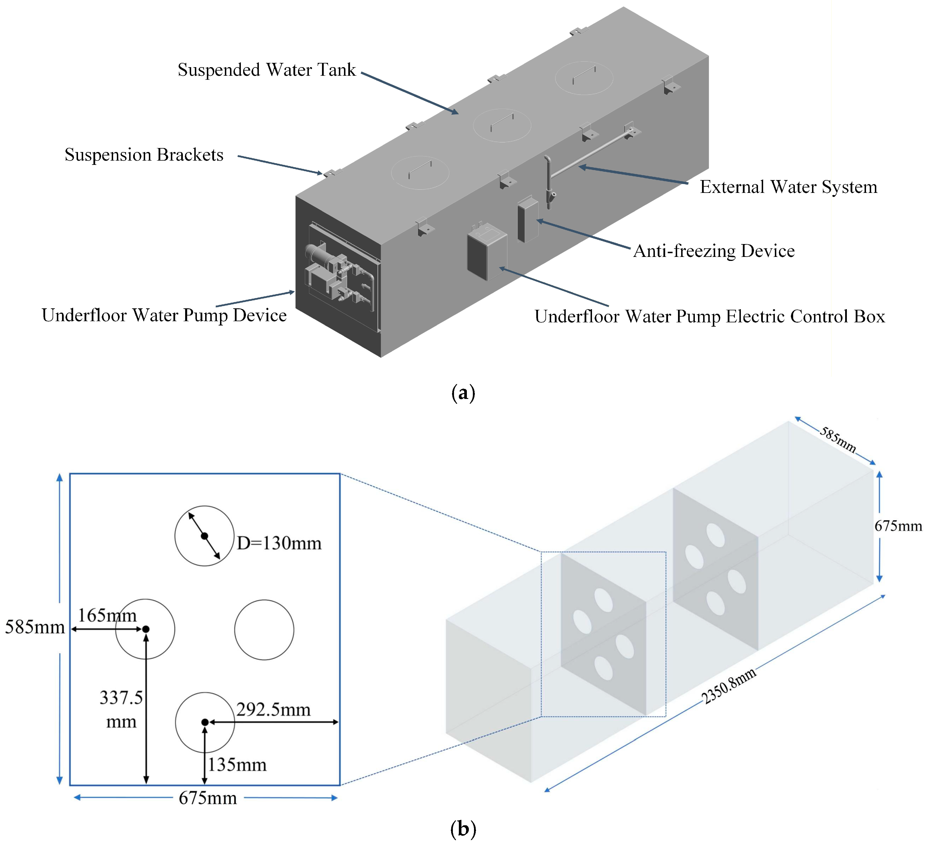
Figure 2.
(a) Water Tank Grid; (b) Fluid Domain Grid.
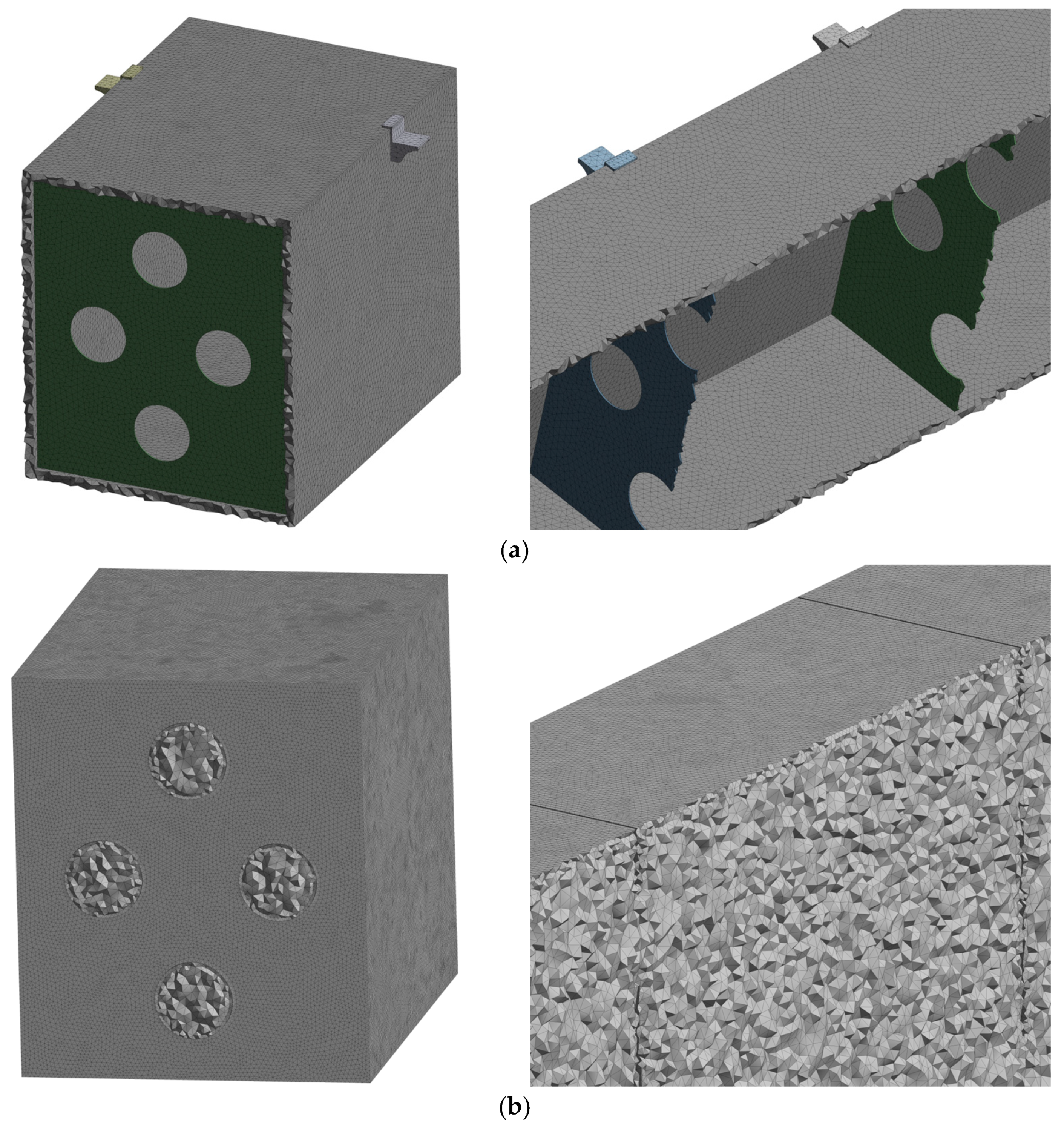
Figure 3.
Two-Way Fluid-Structure Interaction (FSI) Flow Chart.
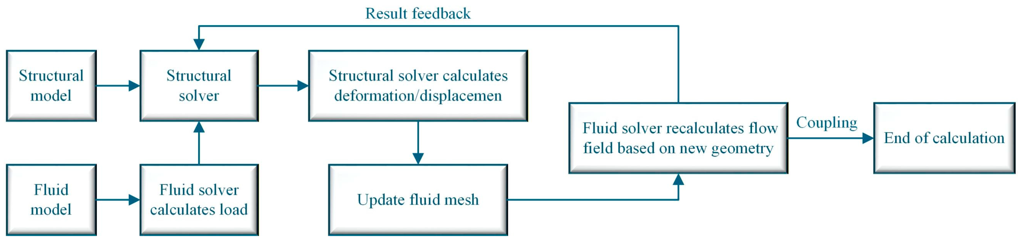
Figure 4.
Impact Load Acceleration Curve.
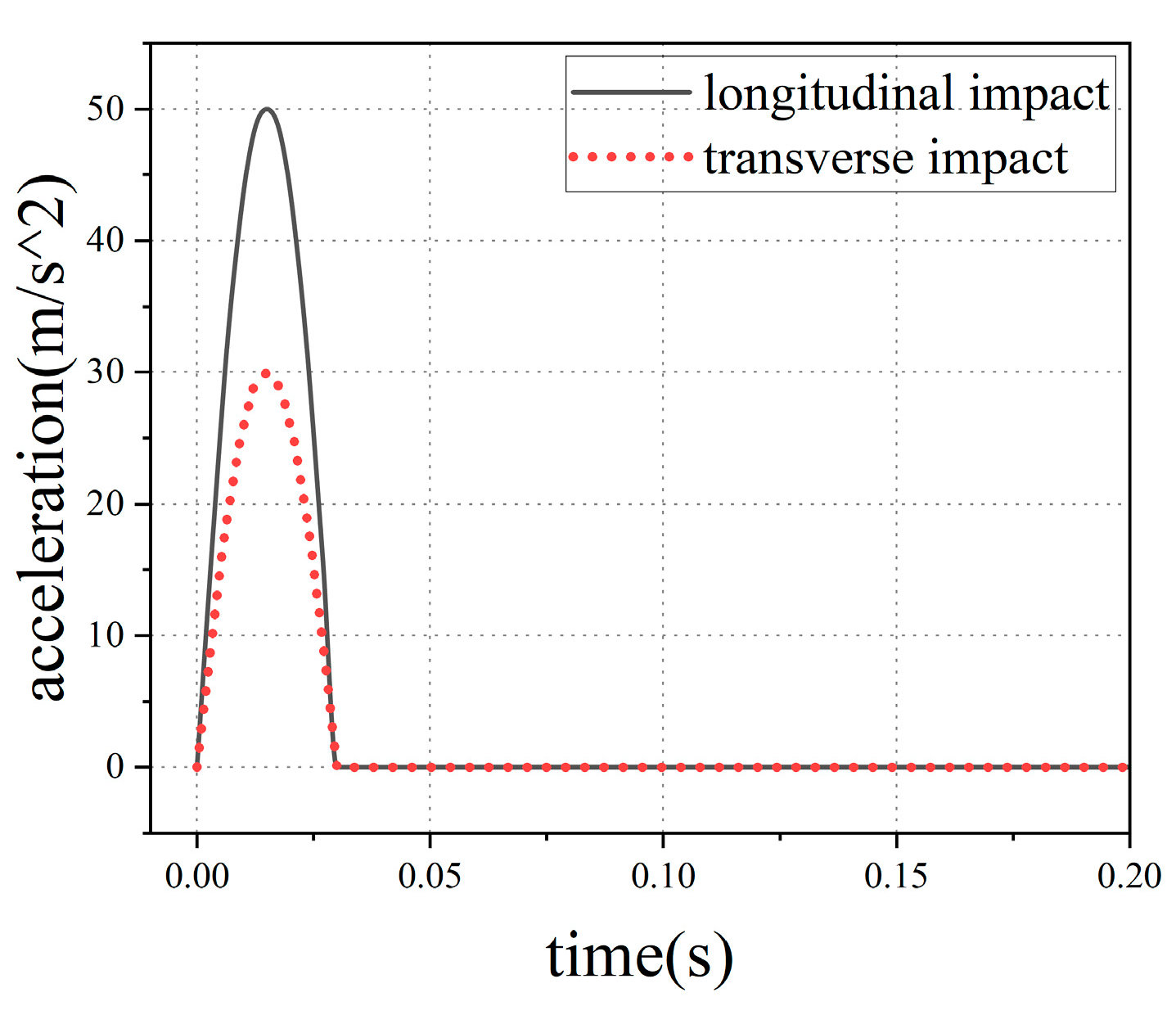
Figure 5.
Schematic Diagram of Bending Wave Radiation in the Baffle.

Figure 6.
(a) Two-Dimensional ABH Plate; (b) Cross-Section Thickness Variation.
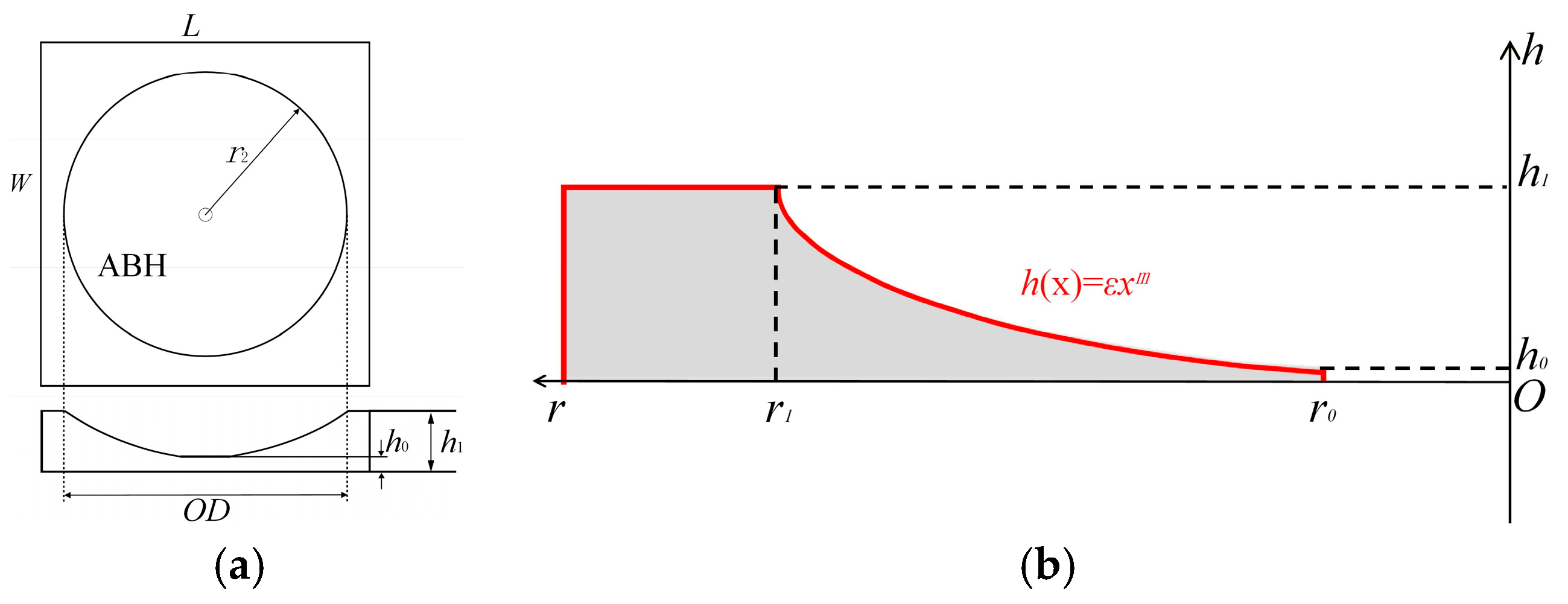
Figure 7.
(a) Time-History Curves of Inner Wall Pressure of Water Tank Under Longitudinal Impact; (b) Time-History Curves of Inner Wall Pressure of Water Tank Under Transverse Impact.
Figure 7.
(a) Time-History Curves of Inner Wall Pressure of Water Tank Under Longitudinal Impact; (b) Time-History Curves of Inner Wall Pressure of Water Tank Under Transverse Impact.
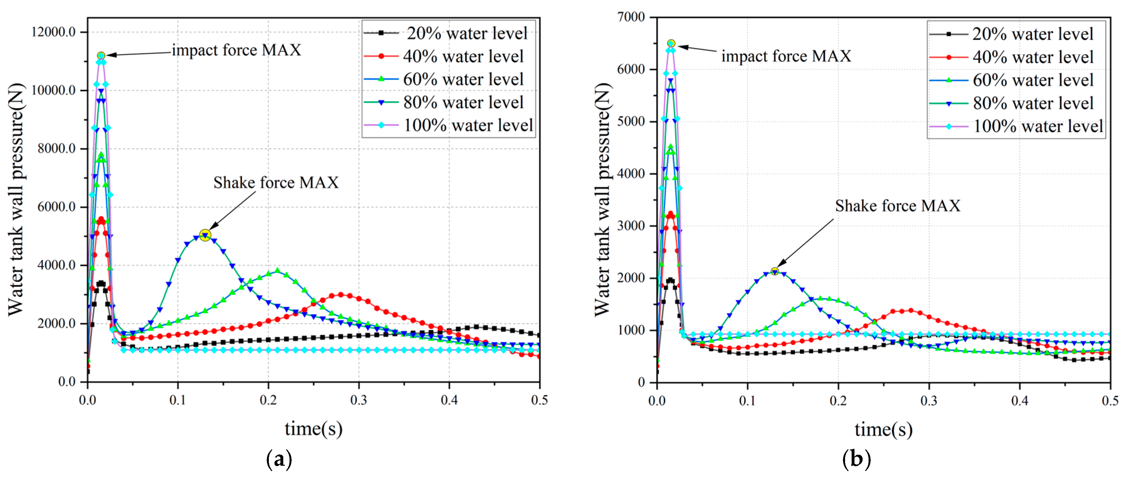
Figure 8.
(a) Schematic Diagram of Liquid Surface Evolution Under Longitudinal Impact; (b) Schematic Diagram of Liquid Surface Evolution Under Transverse Impact.
Figure 8.
(a) Schematic Diagram of Liquid Surface Evolution Under Longitudinal Impact; (b) Schematic Diagram of Liquid Surface Evolution Under Transverse Impact.
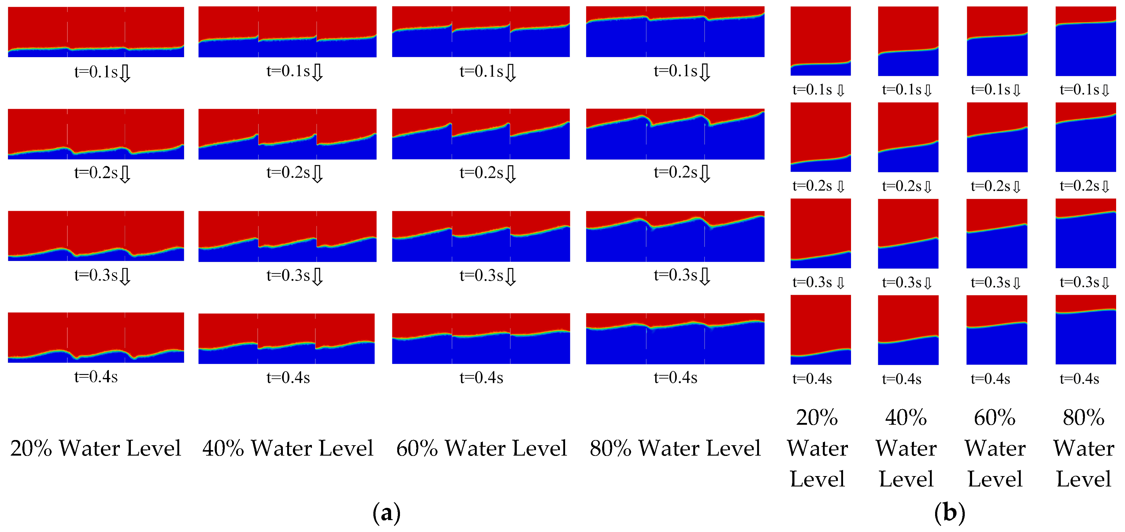
Figure 9.
Schematic Diagram of ABH Embedded in the Baffle.
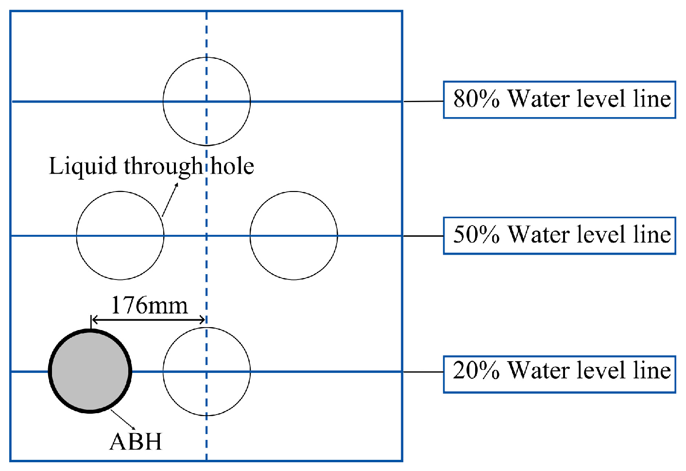
Figure 9.
Orthogonal Test Results.
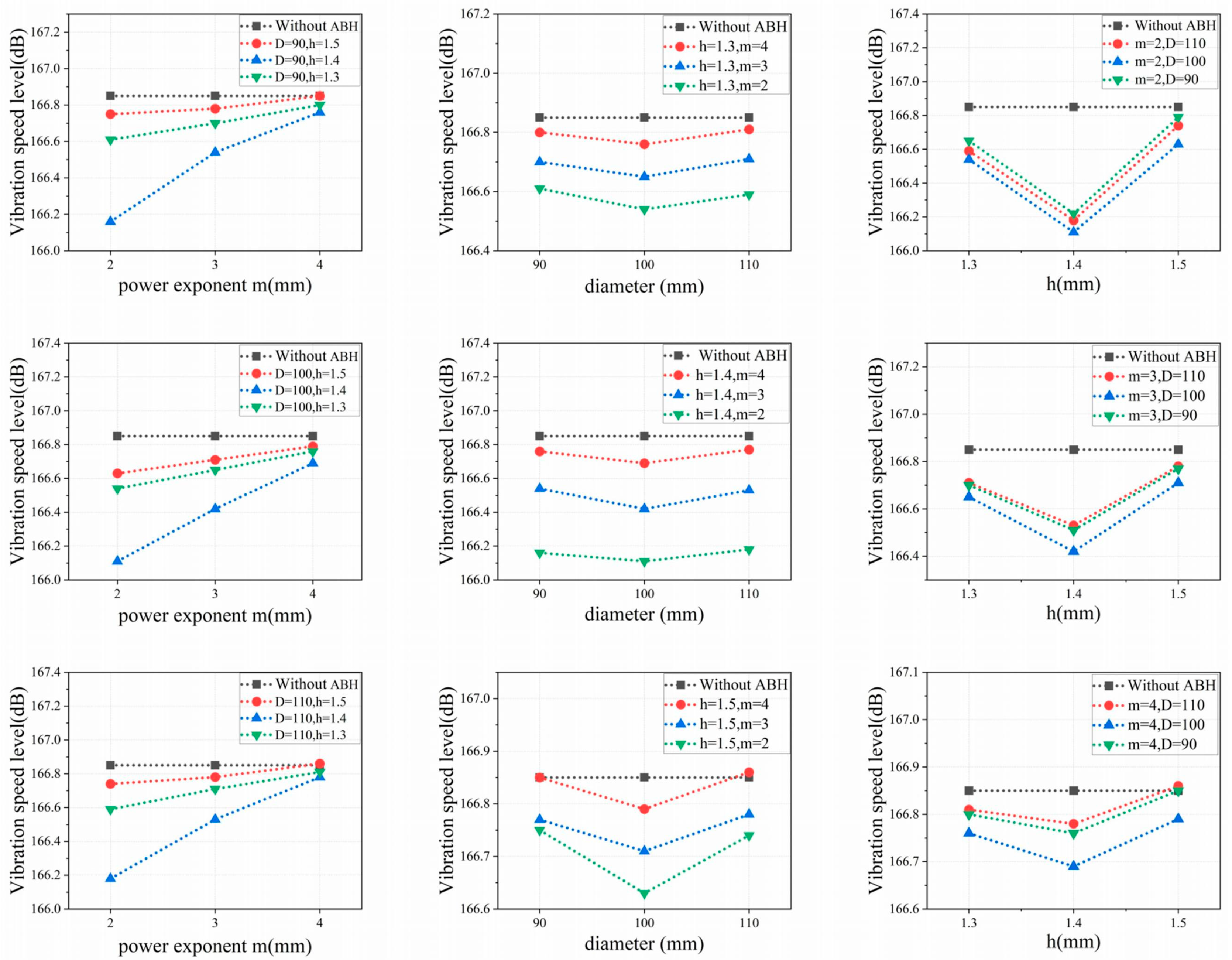
Figure 10.
ABH-Type Baffle.
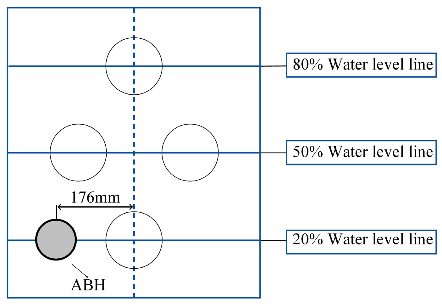
Figure 11.
(a) Water Tank Inner Wall Pressure Under Longitudinal Impact; (b) Baffle Vibration Velocity Level Under Longitudinal Impact; (c) Water Tank Inner Wall Pressure Under Transverse Impact; (d) Baffle Vibration Velocity Level Under Transverse Impact.
Figure 11.
(a) Water Tank Inner Wall Pressure Under Longitudinal Impact; (b) Baffle Vibration Velocity Level Under Longitudinal Impact; (c) Water Tank Inner Wall Pressure Under Transverse Impact; (d) Baffle Vibration Velocity Level Under Transverse Impact.
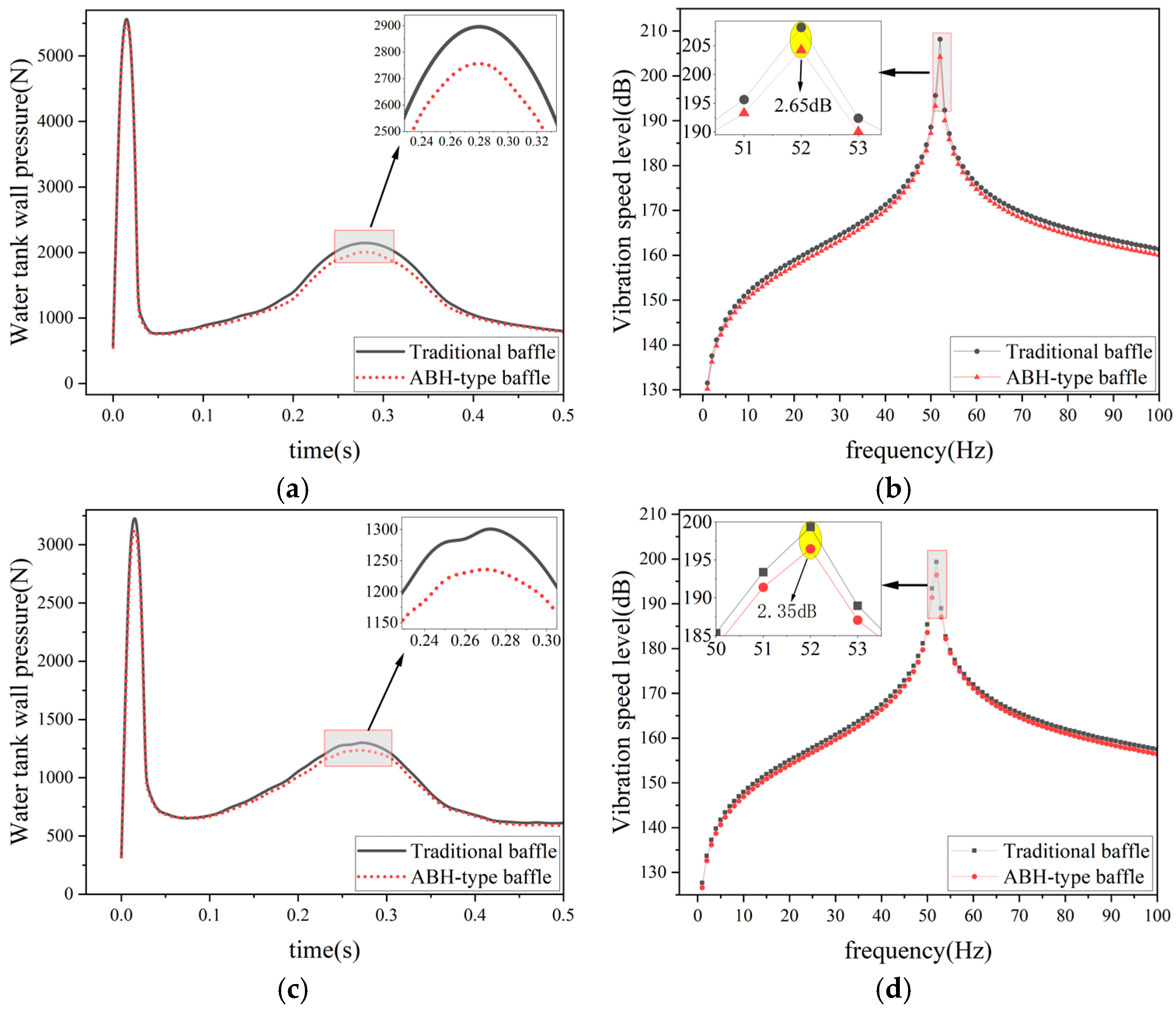
Figure 12.
Direction of Fluid Velocity Vector.
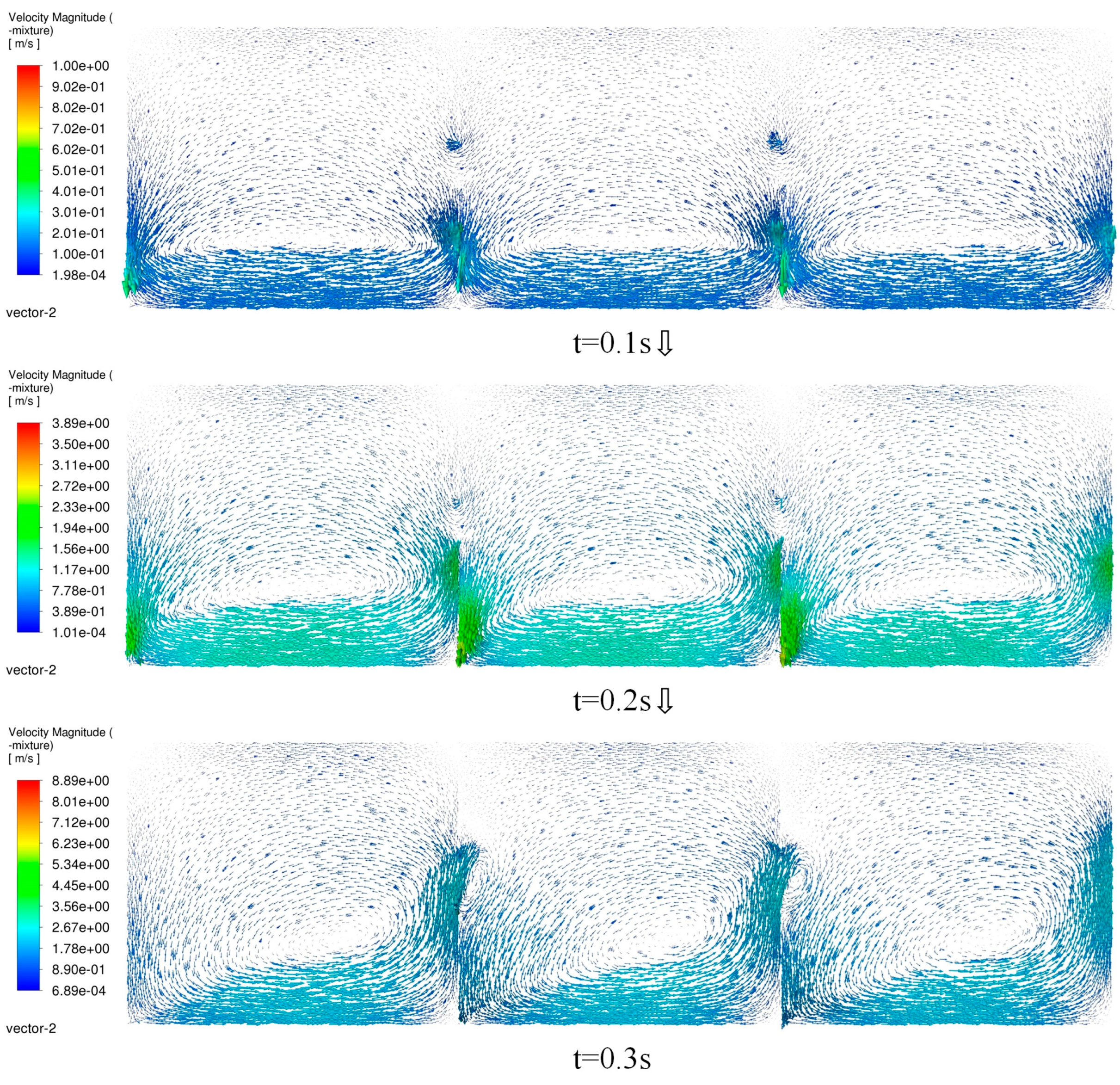
Figure 13.
Position of the ABH.
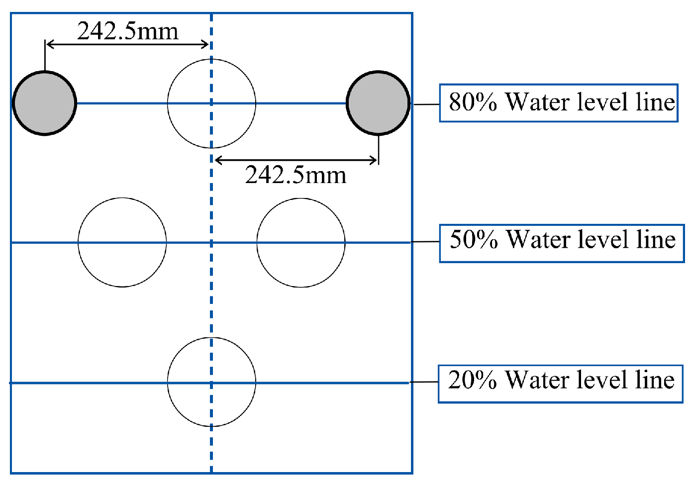
Figure 14.
(a) Wave Suppression Effect; (b) Vibration Suppression Effect; (c) Print 1 – Vibration Energy Cloud Diagram; (d) Control Group – Vibration Energy Cloud Diagram.
Figure 14.
(a) Wave Suppression Effect; (b) Vibration Suppression Effect; (c) Print 1 – Vibration Energy Cloud Diagram; (d) Control Group – Vibration Energy Cloud Diagram.
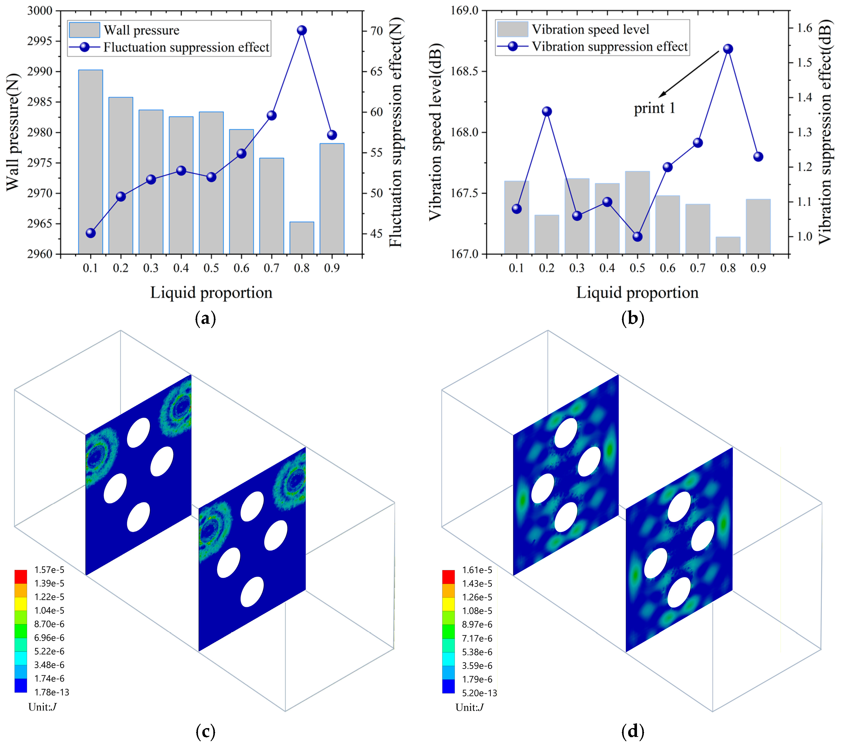
Figure 15.
(a) Scheme 1; (b) Scheme 2; (c) Scheme 3; (d) Scheme 4; € Wave Suppression Effect; (f) Vibration Suppression Effect.
Figure 15.
(a) Scheme 1; (b) Scheme 2; (c) Scheme 3; (d) Scheme 4; € Wave Suppression Effect; (f) Vibration Suppression Effect.
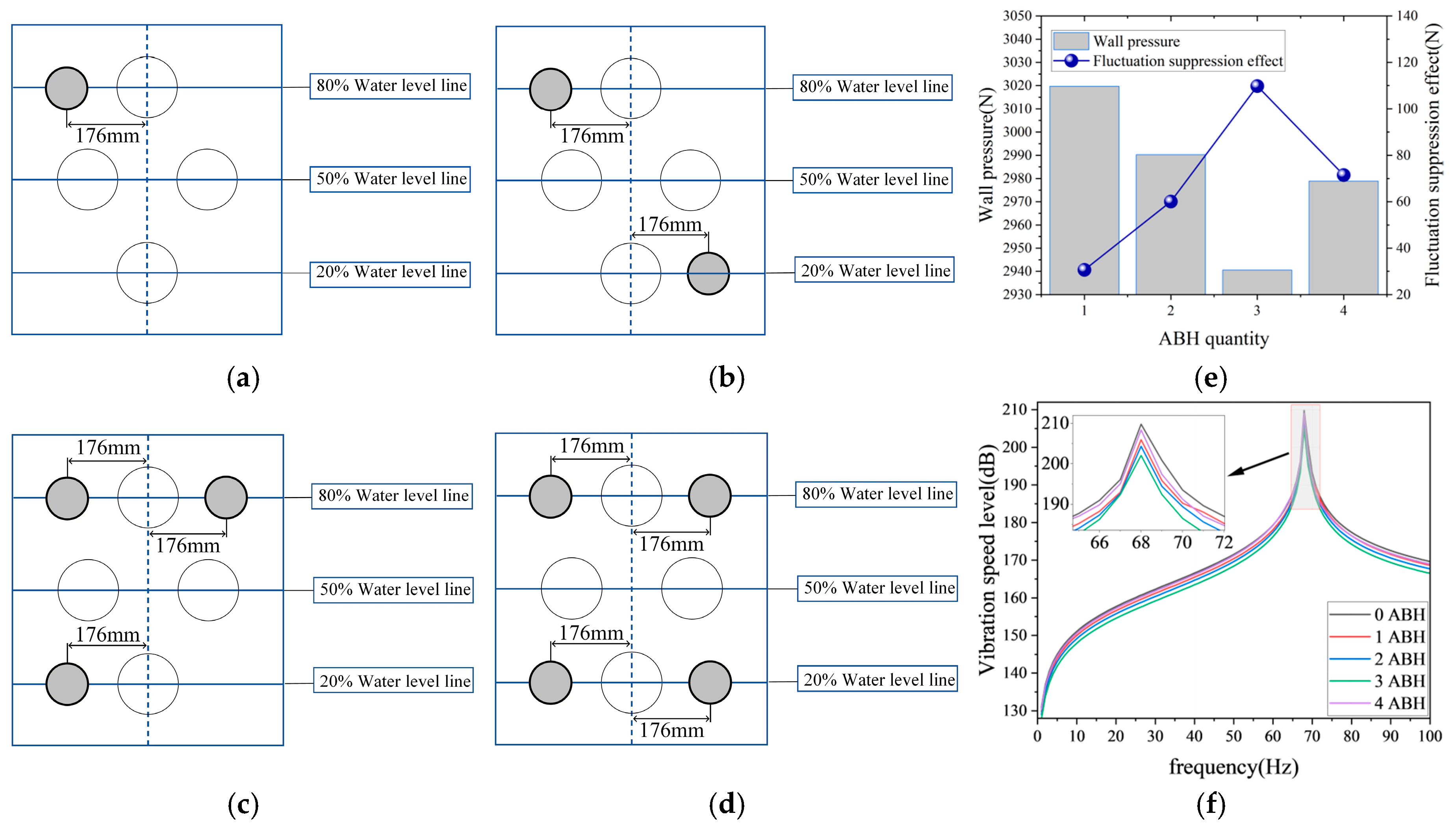
Figure 16.
(a) Front and Rear Surface Pressure of the Baffle; (b) Stress Cloud Diagram of the Baffle.
Figure 16.
(a) Front and Rear Surface Pressure of the Baffle; (b) Stress Cloud Diagram of the Baffle.
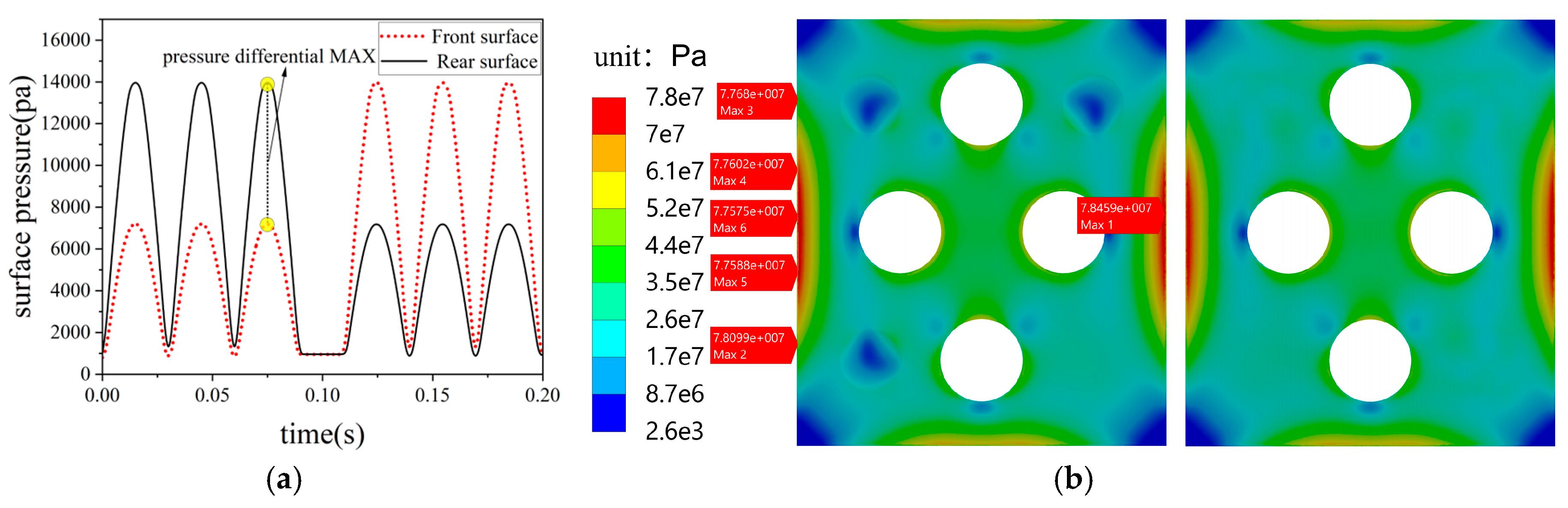
Figure 17.
(a) Baffle Surface Vibration Velocity Level; (b) f=52Hz Two Types of Baffles – Vibration Energy Cloud Diagrams.
Figure 17.
(a) Baffle Surface Vibration Velocity Level; (b) f=52Hz Two Types of Baffles – Vibration Energy Cloud Diagrams.
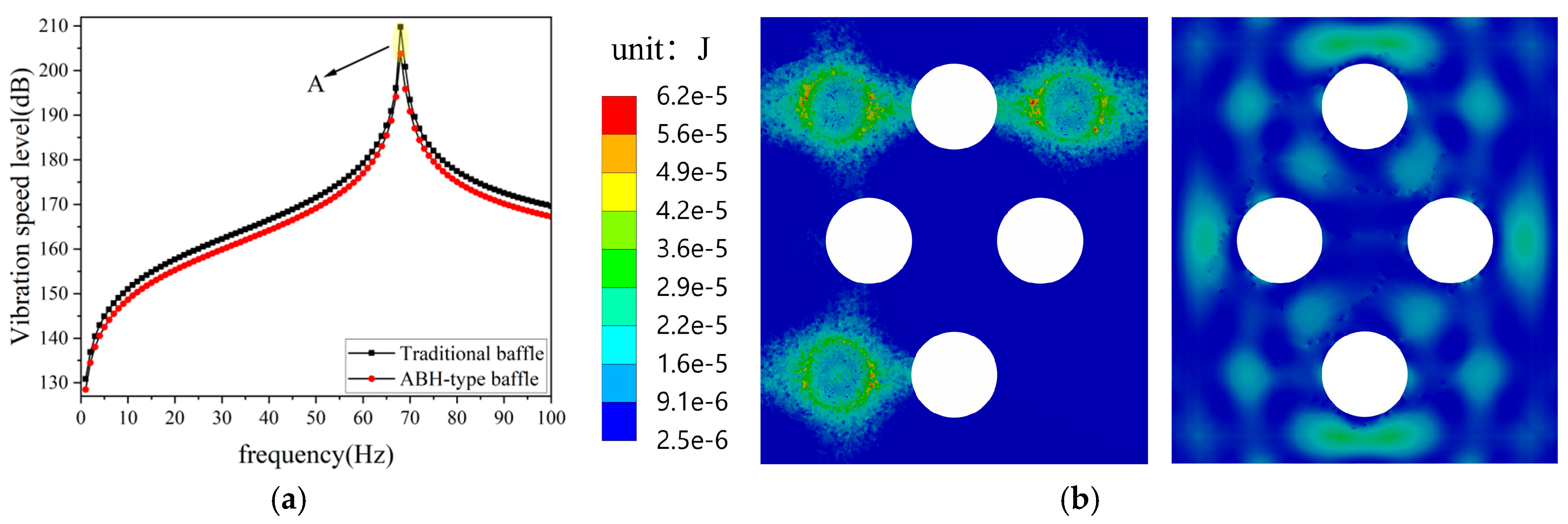
Figure 18.
(a) Longitudinal Impact Water Tank Inner Wall Pressure Variation Curve; (b) Longitudinal Impact Water Tank Inner Wall Pressure Mean Value; (c) Transverse Impact Water Tank Inner Wall Pressure Variation Curve; (d) Transverse Impact Water Tank Inner Wall Pressure Mean Value.
Figure 18.
(a) Longitudinal Impact Water Tank Inner Wall Pressure Variation Curve; (b) Longitudinal Impact Water Tank Inner Wall Pressure Mean Value; (c) Transverse Impact Water Tank Inner Wall Pressure Variation Curve; (d) Transverse Impact Water Tank Inner Wall Pressure Mean Value.
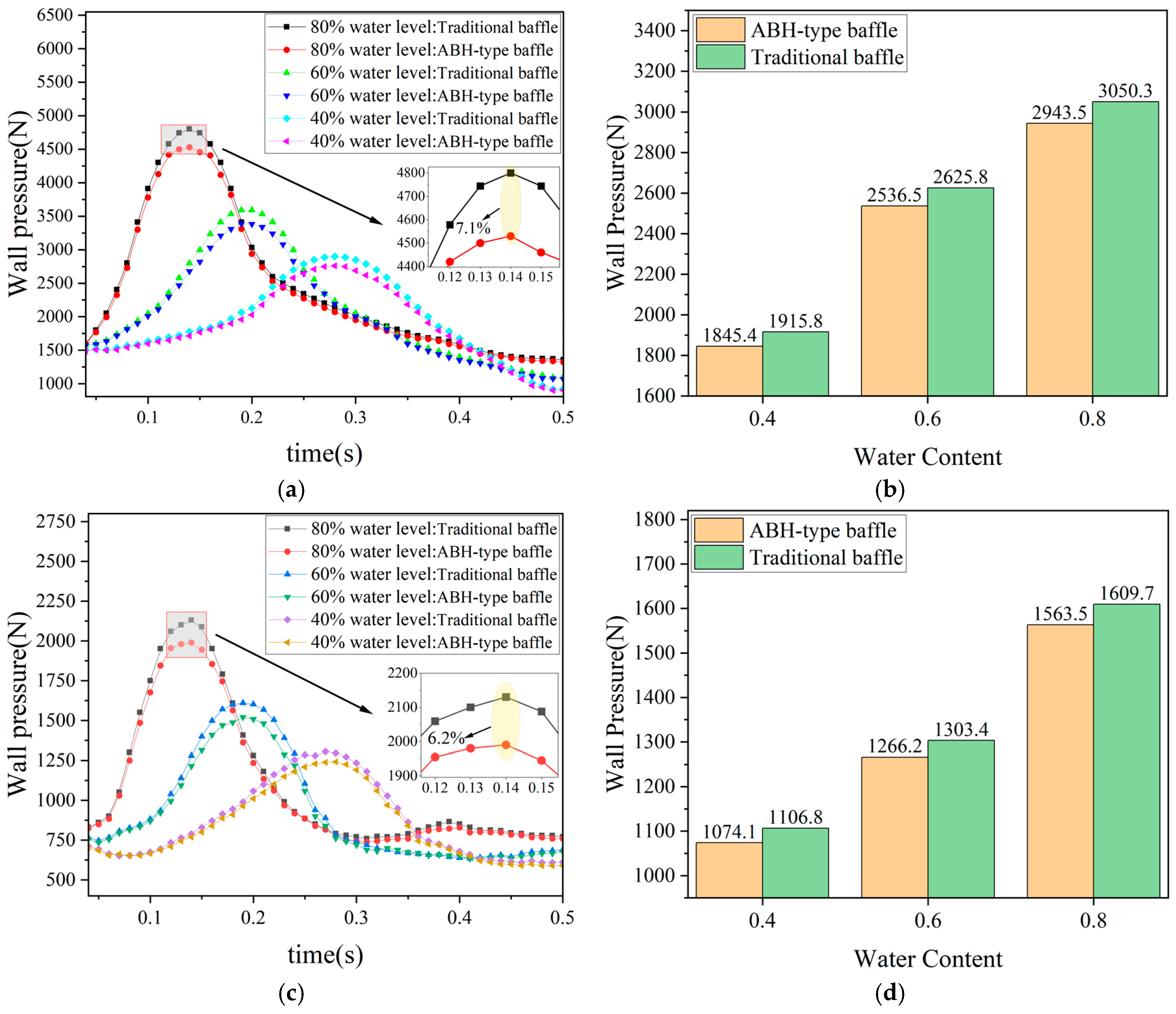
Table 1.
Material Parameters.
| Material Name | Density | Elastic Modulus MPa | Poisson’s Ratio | Yield Strength MPa |
| Q 345 | 7.85×10⁻⁶ | 2.1×10⁵ | 0.3 | 345 |
Table 2.
Grid Independence Verification Data.
| Element Size (mm) | Water Tank | Fluid domain | Pressure(N) | Error | ||
| Element | Node | Element | Node | |||
| 10 | 1220145 | 1955487 | 1684239 | 2422150 | 3372.4 | 1.25% |
| 9 | 1712347 | 2689935 | 2321451 | 3312861 | 3330.3 | 0.31% |
| 8 | 2218330 | 3471522 | 3194665 | 4536107 | 3320.1 | 0.11% |
| 7 | 3219432 | 4963539 | 4502818 | 6362990 | 3316.5 | - |
Table 5.
Test Results.
| Operating Condition | Baffle Type | Average Vibration Velocity Level(dB) | Vibration Suppression Effect(dB) | Average Wall Pressure(N) | Wave Suppression Effect(N) |
| Longitudinal Impact | ABH | 165.47 | 1.18 | 1877.4 | 38.4 |
| Without ABH | 166.65 | -- | 1915.8 | -- | |
| Transverse Impact | ABH | 161.20 | 1.01 | 1085.4 | 21.4 |
| Without ABH | 162.21 | -- | 1106.8 | -- |
Table 6.
Test Results.
| Baffle Type | Average Vibration Velocity Level(dB) | Vibration Suppression Effect(dB) |
| ABH | 165.51 | 3.17 |
| Without ABH | 168.68 | -- |
Disclaimer/Publisher’s Note: The statements, opinions and data contained in all publications are solely those of the individual author(s) and contributor(s) and not of MDPI and/or the editor(s). MDPI and/or the editor(s) disclaim responsibility for any injury to people or property resulting from any ideas, methods, instructions or products referred to in the content. |
© 2026 by the authors. Licensee MDPI, Basel, Switzerland. This article is an open access article distributed under the terms and conditions of the Creative Commons Attribution (CC BY) license.
Copyright: This open access article is published under a Creative Commons CC BY 4.0 license, which permit the free download, distribution, and reuse, provided that the author and preprint are cited in any reuse.


