
Submitted:
08 September 2025
Posted:
10 September 2025
You are already at the latest version
Abstract
This paper examines the effects of strong marine wind on a newly constructed ca-ble-stayed railway bridge with a steel truss girder and a main span of 364 meters over the sea in the maximum single cantilever state. It compares the effectiveness of different wind-resistant measures in mitigating wind-induced vibrations. The results indicate that using the turbulent field parameters and unit aerodynamic admittance function recom-mended in JTG/T 3360-01—2018 Wind-resistant Design Specification for Highway Bridg-es tends to be conservative in predicting the buffeting responses and can be used in the preliminary design of large-span bridges. The measured turbulent field parameters can well estimate the bridge buffeting responses, especially in the transverse direction. Meas-uring wind speeds at the bridge site is crucial for the rational design and construction of cable-stayed bridges in strong marine wind environments. The effectiveness of vibration reduction decreases in the order of temporary piers, inclined struts, tuned mass dampers, and wind-resistant cables. As the addition of temporary piers during the construction of a sea-crossing bridge will significantly increase construction costs, while the inclined strut scheme only requires setting up temporary steel structures near the main tower and piers without significantly increasing construction workload, therefore, the inclined strut scheme is recommended.
Keywords:
railway bridge
; sea-crossing railway
; on-site measurement
; wind-induced effects
; buffeting
; vibration control
The bridge wind-induced vibrations can be categorized into fluttering, buffeting, galloping, and vortex-induced resonance, in which fluttering and galloping are types of divergent vibrations while buffeting and vortex-induced resonance belong to bounded vibrations [1]. Although buffeting is considered a bounded vibration, its amplitude tends to increase super-linearly with the span of the bridge. During the construction of cable-stayed bridges, where the main girder is often constructed with a cantilever, its structural stiffness is significantly lower than that in the completed bridge state, resulting in lower natural frequencies of vibration and damping ratios. Consequently, the main girder is prone to excessive buffeting displacements and acceleration responses, which can compromise the precise installation of bridge components and the overall construction quality. Since high-speed railway bridges with large spans need to meet rigorous stability requirements for the smooth operation of high-speed trains, it imposes even more rigorous accuracy demands on the installation of steel girder cantilevers during construction. Therefore, it is essential to study the wind-induced effects and the vibration control during the cantilever erection of large-span railway bridges in strong wind environments, especially considering recent studies on the non-stationary and turbulence characteristics of typhoon winds [2,3].
The wind-induced effects on large-span bridges under wind loading primarily manifest as vibrations in the main girder, which will further change the surrounding flow field and the aerodynamic forces acting on the main girder, thus creating a coupling effect between the wind loading and the structure. When such a coupling effect is weak, the aerodynamic forces acting on the main girder will induce structural bounded vibrations, including buffeting and vortex-induced vibration. For the latter, it can be effectively suppressed by optimizing the aerodynamic shape of the components’ cross-sections during the bridge’s design. However, for the buffeting induced by pulsating winds, as the bridge’s span increases, the stiffness decreases, especially in areas featuring strong winds such as the areas over the sea and deep-cut valleys. In this sense, the buffeting analysis and vibration control during construction become increasingly prominent.
The buffeting analysis methods proposed in References [4,5] have established a framework for the classic frequency domain analysis of wind-induced bridge buffeting. Building upon this framework, References [6,7,8,9] have systematically considered factors such as aerodynamic nonlinearity, structural nonlinearity, and aerodynamic admittance, etc., proposing the time domain analysis methods for buffeting. References [9,10] have conducted studies on buffeting and vibration control during the construction of large-span bridges using diversified methods and mitigation measures. It has been found that cable-stayed bridges exhibit significant buffeting responses during the construction of cantilever, necessitating the implementation of such measures as wind-resistant cables, temporary supports, or tuned mass dampers (TMDs) for vibration reduction.
This study is conducted against the backdrop of a newly constructed cable-stayed railway bridge with a steel truss girder and a main span of 364 meters over the sea. It analyzes the wind-induced responses during construction, particularly in the maximum single cantilever state. Furthermore, it compares the effectiveness of various wind-resistant measures in suppressing wind-induced vibrations. The findings aim to provide insights into wind-induced vibration mitigation measures for the construction of large-span railway bridges in strong-wind marine areas.
1. Project Background
The Pingtan Straits Rail-cum-Road Bridge is a crucial control project connecting the Fuzhou-to-Pingtan Railway and the Changle-to-Pingtan Expressway. It serves as an extension of the Hefei-Fuzhou Railway and an essential component of the Beijing-Fuzhou transportation corridor. It acts as a rapid passage linking Changle’s sub-center city to the Pingtan Comprehensive Experimental Zone. With a total length of 16.34 km, the railway portion was designed to meet the standards of a double-track Grade I railway with a speed of 200 km/h, while the highway portion was designed as a six-lane expressway with a speed of 100 km/h. It is the world’s longest and also China’s first rail-cum-road bridge over the strait.
This bridge is located at the northern entrance of Haitan Strait, characterized by strong wind, deep water, and high waves, representing a typical strong marine wind environment. The strong wind contains significant pulsating wind, which will lead to structural responses such as buffeting in the steel truss girder, thus imposing higher requirements on the wind resistance performance of the structure and the installation accuracy during the erection of the main girder [11,12]. The bridge spans three navigational channels from north to south in order, namely, Yuanhong Channel, Guyu Gate Channel, and Daixiaolian Island Channel. The main bridge over the Guyu Gate Channel adopts a double-tower double-cable-plane steel truss cable-stayed bridge with a main span of 364 meters, spanning a total length of 928 meters. The bridge span is arranged as (128+154+364+154+128) meters respectively, as shown in Figure 1. The stayed cables are arranged in a spatial double-cable-plane configuration with a fan-shaped layout, with a longitudinal spacing of 14.0 meters and a transverse spacing of 35.6 meters on the girder. The vertical cable spacing on the tower is 2.5 meters, with a transverse spacing of 44.0 meters.
2. Finite Element Model
The main girder of the Guyu Gate Channel Bridge adopts a form of plate girder with a stiffening girder. The bridge deck consists of both concrete and partially steel deck slabs. A finite element model of the Guyu Gate Channel Bridge was established, with material properties and element types listed in Table 1. Considering factors such as bolted and welded Gusset plates, which would increase the weight of the main girder, the density of the main girder steel material has been increased by 15%, resulting in a density of 9027.5 kg/m3 (7850 × 1.15).
Define the x-axis as the longitudinal direction of the bridge, the y-axis as the transverse direction, and the z-axis as the vertical direction. The main tower, the side piers, and the auxiliary piers are all rigidly supported at their bases. At the main tower, the tower girder constrains the main girder’s linear displacements in the vertical, transverse, and longitudinal directions. In contrast, at the auxiliary piers and side piers, the tower girder constrains the main girder’s linear displacements in the vertical and transverse directions. The natural frequencies and mode of vibration of the Guyu Gate Channel Bridge in the maximum single cantilever state are obtained through dynamic characteristic analysis, as shown in Table 2.
3. Impacts of Strong Marine Wind on the Construction of Cable-Stayed Bridges with a Steel Truss Girder
Under the action of natural wind, the structural internal force responses mainly consist of two parts: one is the structural internal force under the action of the mean wind, and the other is the structural internal force caused by the buffeting under the action of the pulsating wind. To investigate the impacts of mean wind on the construction of railway cable-stayed bridges with a steel truss girder in strong marine environments, static wind loads are applied to the model to study the variations in structural displacements, internal forces, and cable tensions induced by mean wind.
3.1. Static Wind Load
Under the action of static wind loads, the static wind resistance force (FH), the lift force (FV), and the torsional moment (M) per unit length of the bridge section are represented as follows:
Where ρ represents the air density (taken as 1.225 kg/m3), U denotes the mean wind speed, H stands for the girder height (taken as 15.3 m), B represents the girder width (taken as 36.8 m), and CH, CV, and CM respectively denote the resistance coefficient, the lift coefficient, and the torsional moment coefficient of the main girder, which can be obtained through wind tunnel experiments.
According to the wind tunnel experiment research reports, the main girder’s resistance coefficient, lift coefficient, and moment coefficient are 0.6452, 0.0308, and 0.1065, respectively at a wind attack angle of 0°. For components such as bridge towers and cables, only the effects of resistance are considered in the calculation. When calculating the wind loads on bridge towers and cables, the wind speed at different heights is considered according to the variation of the wind profile. The resistance coefficient CD is taken from the value specified in JTG/T 3360-01—2018 Wind-resistant Design Specification for Highway Bridges, that is,
Where FD refers to the wind loads in the horizontal direction and D refers to the pillar width or the cable’s outer diameter.
3.2. Displacement Response Under Wind Loads
During the construction of the Guyu Gate Channel Bridge in the maximum single cantilever state, under the condition of a designed wind speed of 51.4 m/s and a current wind attack angle of 0°, the static wind displacements at the cantilever end of the main girder and the top of the bridge tower are listed in Table 3. Under the action of wind in the transverse direction, the vertical and lateral displacements at the cantilever end of the main girder in the maximum single cantilever state are 5.1 mm and 79.7 mm, respectively. Assuming the resistance coefficients on the windward and leeward sides of the main tower and the main girder are the same, the windward and leeward sides of the main girder experience increased lateral deformation, resulting in lateral displacements much larger than vertical displacements.
During the construction of railway steel truss cable-stayed bridges, particular attention is paid to the influence of displacements at the cantilever end of the main girder. The static wind displacements of the main span at the cantilever end under wind speeds ranging from 5.0 to 51.4 m/s are depicted in Figure 2. It can be observed that the static wind displacements at the cantilever end of the main girder increase nonlinearly with increasing wind speed, with lateral displacements being predominant. construction activities should be avoided under high wind speed, and combined thermal–wind effects should also be considered for safe erection [13,14].
3.3. Cable Tensions Under Static Wind Loads
During the construction of railway cable-stayed bridges, in order to ensure the structural safety and control the alignment of the main girder, it requires calculating the cable tensions under the average wind load for each construction stage, in preparation for secondary cable tensioning after closure. The cable tensions under different wind speeds are depicted in Figure 3.
From Figure 3, it can be observed that the windward-side cable tensions (BS01 and MS01) near the main tower increase with the increasing wind speed, while the cable tensions on the leeward side decrease with the increasing wind speed. The cable tensions of the lateral cable (BS09) away from the main tower tend to decrease with increasing wind speed, but the magnitude differs between the windward and leeward sides, with a larger magnitude on the leeward side. This phenomenon is related to the aerodynamic torsional moment of the main girder. Therefore, during cable tensioning construction, it is necessary to control the cable tensions near the main tower to prevent excessive variations in tension, which may lead to relaxation. For cables further away from the main tower, where tensions are higher, attention should be paid to ensuring tensioning accuracy.
When the tensioning of the No. 9 stayed cable at Tower Z03 is completed, the corresponding state is that of the maximum single cantilever. At this point, a comparison can be made between the measured cable tension values and the values obtained from finite element analysis. The measured cable tension corresponds to weather conditions with wind speed at Beaufort scale 8. According to JTG/T 3360-01, the wind speed at a height of 10 meters above the ground (Us10) ranges from 17.2 to 20.7 m/s. On this basis, the designed wind speed (Usd) for the construction of the main girder can be determined as:
Where ksf represents the wind risk coefficient during construction, which can be obtained based on the reference wind speed at 10 meters above the ground and the construction period. For this bridge, it is taken as 0.92; Z denotes the elevation of the main girder.
According to Equation (5), the wind speed at the bridge deck is calculated as 19.72~23.7 m/s. For conservative estimation, the stayed-cable tensions are compared with the measured results at an average wind speed of 25 m/s, as shown in Table 4. It can be observed that there are discrepancies between the finite element calculated values and the measured values, with smaller errors on the windward side and larger errors on the leeward side. This is attributed to the susceptibility of the side span’s mid-span and the cantilever end of the main span to construction disturbances, which can affect the vibration and consequently the tension of the stayed cables.
4. Buffeting Response Prediction
4.1. Calculation Conditions
The Complete Quadratic Combination (CQC) method [15] was applied to calculate the acceleration response at the cantilever end of the main girder under different wind speeds at the maximum single cantilever stage. According to wind tunnel test data, the first-order derivatives of the resistance, the lift force, and the moment coefficients (CD’, CL’, and CM’) at a wind attack angle of 0° are 0.3266, 4.3144, and 0.6088, respectively. In the simulation of self-excited forces, the horizontal aerodynamic derivatives were calculated based on quasi-steady theory, while for other directions, similar results from a bridge (e.g., the Oresund Bridge) were utilized. The sectional aerodynamic derivatives are shown in Figure 4. In the figure, Hi* and Ai* (I = 1, 2, 3, 4) are the flutter derivatives of the bridge section, all of which are functions of the reduced frequency U/(Fb) [15].
The structural damping ratio was assumed to be 0.005 according to JTG/T 3360-01 for steel truss girder structures. The buffeting response analysis considered the first 10 natural modes, with a frequency interval of approximately 0.001 within the range of 0.001 to 2 Hz. Davenport’s along-wind and vertical turbulence velocity spectra were adopted along with span coherence models, with a decay coefficient assumed to be 7 [16]. The aerodynamic admittance functions of the main girder were assumed to be either 1 (the unit function) or the Sears function.
Three scenarios (as shown in Table 5) were designed for buffeting analysis. The relationship among the measured along-wind and vertical turbulence intensity, the turbulence integral scale, and the average wind speed is depicted in Figure 5, indicating the turbulence intensity decreases approximately with increasing average wind speed, while the turbulence integral scale increases approximately with increasing average wind speed. For Scenario 1 and Scenario 2, the turbulence parameters recommended in the Wind-resistant Design Specification for Highway Bridges and those measured at the site were adopted, respectively. In both scenarios, the aerodynamic admittance functions of the main girder adopted the unit function (equal to 1 for the entire frequency range). In Scenario 3, the same turbulence parameters as Scenario 2 were utilized, while the aerodynamic admittance function adopted the Sears empirical function.
4.2. Result Analysis
The comparison between measured and numerical values of buffeting response under Scenario 1 and Scenario 2 is illustrated in Figure 6. The measured standard deviation of acceleration is generally lower than the numerical solutions, suggesting that the results obtained using the specified standard turbulence parameters may overestimate the structural buffeting response. It is recommended to use measured turbulence parameters for calculating the structural buffeting response, which is consistent with recent findings on non-Gaussian turbulence and typhoon–hurricane field measurements [17,18].
Figure 7 illustrates the standard deviation of acceleration response obtained through field measurements and numerical analysis under Scenario 2 and Scenario 3 conditions. The calculated results based on the Sears function for the main girder’s aerodynamic admittance are lower than the measured response in the field, indicating a significant underestimation of the buffeting response when using the Sears aerodynamic admittance for buffeting response analysis. Additionally, it can be observed that the choice of the main girder aerodynamic admittance function has a crucial impact on buffeting response analysis. Relatively, when the main girder aerodynamic admittance adopted the unit function, the predicted buffeting values were closer to the measured values in the field, especially in the transverse response. The differences between the field-measured results and numerical results under Scenario 2 and Scenario 3 conditions are likely attributed to the selection of the main girder aerodynamic admittance function. Therefore, it is imperative to accurately and reliably identify the main girder sectional aerodynamic admittance function in future wind tunnel experiments.
According to Article 6.0.2 and related provisions in GB 50868-2013 Standard for Allowable Vibration of Building Engineering, it is stipulated that in vibrating work environments, the vibration limit at which the attention of operators shifts and work efficiency decreases be defined as the fatigue-work efficiency reduction limit, while the vibration limit that maintains the physiological and psychological comfort of the human body be defined as the comfort reduction limit. The vertical and transverse accelerations of the main girder are determined using the 1/3 octave method. The fatigue-work efficiency reduction limits for vertical (112 Db) and horizontal (107 Db) accelerations are considered as the general operation limits for activities such as welding, with an exposure time of 8 hours. The comfort reduction limits for vertical (109 Db) and horizontal (104 Db) accelerations, with an exposure time of 2.5 hours, are considered special operation limits. Therefore, by inversely deducing the wind speed from the acceleration under buffeting effects, suggested wind speeds that are unsuitable for lifting operations and welding operations are obtained respectively.
5. Measures for Vibration Control in the Maximum Single Cantilever State
To control the vertical and horizontal buffeting responses at the cantilever end of the Guyu Gate Channel Bridge during the maximum single cantilever construction, four damping measures including the addition of inclined struts, auxiliary piers, temporary wind cables, and Tuned Mass Dampers (TMDs) were analyzed using the buffeting time-domain method. A comparison was also made with the buffeting response of the original structure (without measures). By solving the root mean square values of buffeting responses at the cantilever end of the main girder and the top of the main tower before and after the adoption of damping measures, the effectiveness of different wind-resistant measures in reducing the root mean square of vertical, longitudinal, and transverse buffeting displacements at the cantilever end of the main girder and the top of the tower can be determined. This has provided a basis for the formulation of buffeting control measures during the construction of large-span cable-stayed bridges across the sea.
5.1. Model Scenarios Without Wind-Resistant Measures
Table 6 shows the models and their working conditions of different wind-resistant measures for the Guyu Gate Channel Bridge in the maximum single cantilever state. It should be noted that in Scenario 2, the inclined strut scheme adopts inclined struts to constrain the degrees of freedom of the abutments, the auxiliary piers, and the main girder at the main tower, firmly securing the inclined struts to the main girder. Moreover, assuming that the inclined struts have very high rigidity, the displacements at the main girder anchorage can be ignored. In Scenario 3, the temporary pier scheme involves setting up a temporary pier at the midpoint of the maximum cantilever end of the main girder, anchoring the main girder to the temporary pier vertically and horizontally. In Scenario 4, the wind-resistant cable scheme uses four symmetrical wind cables connected to both sides of the bridge tower, with one end fixed to the top surface of the main tower pedestal and the other end fixed to the anchorage point of the main girder and the stayed cable. Thus, these wind-resistant cables can be temporarily anchored symmetrically at the No. 4 cable of the main girder, with the main girder’s anchorage point 56 meters away from the centerline of the bridge tower, and the angle between the wind-resistant cable and the vertical direction of the main beam being 43.25°. Considering that the steel strand cables have significant damping, 42-strand 15.2mm steel strand cables (with an area of 5,814 mm2) have been applied as wind-resistant cables, with a stress of 150 Mpa and a length of 85.78 meters. In Scenario 5, the TMD scheme involves the addition of vertical and horizontal TMDs at the cantilever end of the main girder.
The buffeting response analysis was conducted for the original structure of the Guyu Gate Channel Bridge at its maximum single cantilever state and for the structure after the adoption of various wind-resistant measures. The analysis considered a wind attack angle of 0° and a wind yaw angle of 0° during the construction of the main girder. Under a wind attack angle of 0°, the static force coefficients and their derivatives for the main girder’s section are as follows: CD = 0.6452, CL = 0.0308, CM = 0.1065, CD’ = 0.3266, CL’ = 4.3144, and CM’ = 0.6088, respectively.
5.2. Vibration Control Analysis
The coupled buffeting analysis was applied to calculate the root mean square (RMS) of the transverse and vertical vibration responses at the cantilever end of the main girder for the five scenarios. To evaluate the damping effect of the Tuned Mass Damper (TMD) scheme, the first 20-order damping ratios involved in the calculation were set as equivalent damping ratios correspondingly. The RMS values of the vertical and transverse displacements of the main girder under different wind-resistant measures (U=51.8 m/s) are shown in Figure 8. It can be observed that the adoption of inclined struts and auxiliary piers can effectively reduce the transverse and vertical displacements of the main girder’s cantilever end, while the measures of wind-resistant cables and TMD have shown poorer control effects on the buffeting response.
To further investigate the damping effect of different wind-resistant measures on the buffering response of the main girder, the root mean square (RMS) values of the transverse and vertical displacement buffeting responses of the main girder at the cantilever end were compared, with the results shown in Table 7. Here, η represents the effectiveness of the wind-resistant measures, defined as:
Where σc refers to the root mean square (RMS) of the vibration response at the main girder’s cantilever end without any damping measures, and σb refers to the RMS of the vibration response at the main girder’s cantilever end with damping measures.
Table 7 indicates that the reduction in vertical and transverse buffeting response at the main girder’s cantilever end is most significant with the use of inclined struts and auxiliary piers, while the damping effect of wind-resistant cables is minimal, which is attributed to the positioning of the wind-resistant cables. In the wind-resistant cable scheme, one end of the cable can only be anchored to the base of the main tower, and the angle with the vertical direction is relatively large, resulting in limited damping effectiveness. The damping effect of the TMD scheme is not very ideal, ranging from 8% to 10%, which is attributed to the structural vibration mode in the maximum cantilever state during construction, where there is no vertical or transverse sway of the main girder, resulting in limited damping effect when the TMD acts on the cantilever end. This highlights the importance of integrating real-time monitoring technologies, such as satellite-based displacement monitoring, to support vibration control and ensure construction safety [19].
Overall speaking, the auxiliary piers have exhibited the best damping efficiency. However, it costs more to construct submerged piers while increasing construction complexity and workload for sea-crossing bridge projects. On the contrary, the diagonal bracing scheme involves only setting up temporary steel structural inclined struts near the main tower and piers, without significantly increasing construction difficulty or workload. For sea-crossing railway bridges or bridges with even larger spans, the latter scheme stands out.
6. Conclusions
The predictions of the buffeting responses based on the recommended turbulence field parameters and unit aerodynamic admittance function specified in (JTG/T 3360-01-2018) Wind-resistant Design Specification for Highway Bridges tend to be conservative, making them suitable for the preliminary design of long-span bridges.
2) The measured turbulence field parameters may well estimate the bridge buffeting responses, especially in the transverse direction. Measuring wind speeds at bridge sites is of great significance for the rational design and construction of cable-stayed bridges in strong marine wind environments.
3) The vertical and transverse accelerations of the main girder are determined using the 1/3 octave method. The vertical and horizontal limits for on-site welding and other general operations are based on the 8-hour fatigue-effectiveness reduction limit, while the vertical and horizontal limits for special operations are based on the 2.5-hour comfort-effectiveness reduction limit.
4) The damping effects of temporary piers, inclined struts, TMD, and wind-resistant cables decrease in order. Since the addition of temporary piers during the construction of a sea-crossing bridge significantly increases construction costs, while the inclined strut scheme only requires the installation of temporary steel struts near the main tower and piers without significantly increasing the construction workload, therefore, the inclined strut scheme is recommended.
Author Contributions
Conceptualization, Z.F.; methodology, Z.F.; formal analysis, Z.F.; investigation, Z.F; data curation, Z.F.; writing—original draft preparation, Z.F. and Y.Z.; writing—review and editing, Z.F. and Y.Z.. All authors have read and agreed to the published version of the manuscript.
Funding
This study was funded by the National Key R&D Program of China (No. 2022YFB2602900), Sichuan Science and Technology Program (No. 2023ZDZX0030), the Science and Technology Research and Development Project of China State Railway Group (No. K2023G038), the Major Project of China Academy of Railway Sciences Group (No. 2023YJ182), and the Scientific Research and Development Project of China Railway Shanghai Bureau Group Co., Ltd. (No. 2022154).
Institutional Review Board Statement
Not applicable.
Informed Consent Statement
Not applicable.
Data Availability Statement
Data are available upon reasonable request at the Corresponding Authors.
Conflicts of Interest
The authors declare no conflict of interest.
References
- Xu, Z.; Dai, G.; Zhang, L.; Chen, Y.F.; Flay, R.G.; Rao, H. Effect of non-Gaussian turbulence on extreme buffeting response of a high-speed railway sea-crossing bridge. J. Wind. Eng. Ind. Aerodyn. 2022, 224. [CrossRef]
- Huang, Z.; Xu, Y.-L.; Tao, T.; Zhan, S. Time-varying power spectra and coherences of non-stationary typhoon winds. J. Wind. Eng. Ind. Aerodyn. 2020, 198. [CrossRef]
- Zhao, L.; Cui, W.; Ge, Y. Measurement, modeling and simulation of wind turbulence in typhoon outer region. J. Wind. Eng. Ind. Aerodyn. 2019, 195. [CrossRef]
- Scanlan, R. The action of flexible bridges under wind, II: Buffeting theory. J. Sound Vib. 1978, 60, 201–211. [CrossRef]
- Isyumov, N. Alan G. Davenport’s mark on wind engineering. Journal of Wind Engineering & Industrial Aerodynamics, 2012, 104-106, 12–24.
- Chen, X.; Matsumoto, M.; Kareem, A. Time Domain Flutter and Buffeting Response Analysis of Bridges. J. Eng. Mech. 2000, 126, 7–16. [CrossRef]
- Cui, W.; Zhao, L.; Ge, Y. Non-Gaussian turbulence induced buffeting responses of long-span bridges based on state augmentation method. Eng. Struct. 2022, 254. [CrossRef]
- Xu, Y.; Liu, T.; Zhang, W. Buffeting-induced fatigue damage assessment of a long suspension bridge. 2008, 31, 575–586. [CrossRef]
- Kim, H.-K.; Kim, K.-T.; Lee, H.; Kim, S. Performance of Unpretensioned Wind Stabilizing Cables in the Construction of a Cable-Stayed Bridge. J. Bridg. Eng. 2013, 18, 722–734. [CrossRef]
- Sham, S.R.; Wyatt, T.A. Construction aerodynamics of cable-stayed bridges for record spans: Stonecutters Bridge. Structures 2016, 8, 94–110. [CrossRef]
- Zhou, R.; Jia, X.; Li, J.; Li, D.; Lu, P.; Zong, Z. Wind–Temperature Characteristics of a Cable-Stayed Bridge along the Yellow Sea under Superstrong Typhoon Lekima. J. Bridg. Eng. 2024, 29. [CrossRef]
- Li, J.; Yang, X.; Lei, Y.; Chang, T.; Zhang, J.; Peng, Y. Probabilistic structure analysis of fluctuating wind speed based on field measurement of super typhoon Doksuri. J. Wind. Eng. Ind. Aerodyn. 2024, 253. [CrossRef]
- Zhu, Y.; Sun, D.; Shuang, M. Investigation of temperature-induced effect on rail-road suspension bridges during operation. J. Constr. Steel Res. 2024, 215. [CrossRef]
- Zhu, Y.; Sun, D.; Guo, H.; Shuang, M. Fine analysis for non-uniform temperature field and effect of railway truss suspension bridge under solar radiation. J. Constr. Steel Res. 2023, 210. [CrossRef]
- Scanlan, R. The action of flexible bridges under wind, I: Flutter theory. J. Sound Vib. 1978, 60, 187–199. [CrossRef]
- Peng, Y.; Wang, S.; Li, J. Field measurement and investigation of spatial coherence for near-surface strong winds in Southeast China. J. Wind. Eng. Ind. Aerodyn. 2018, 172, 423–440. [CrossRef]
- Zhu, Y.; Shuang, M. Influence of non-Gaussian characteristics of wind load on fatigue damage of wind turbine. WIND AND STRUCTURES, 2020, 31 (3), 217–227.
- Li, L.; Kareem, A.; Xiao, Y.; Song, L.; Zhou, C. A comparative study of field measurements of the turbulence characteristics of typhoon and hurricane winds. J. Wind. Eng. Ind. Aerodyn. 2015, 140, 49–66. [CrossRef]
- Zhu, Y.; Shuang, M.; Sun, D.; Guo, H. Algorithm and Application of Foundation Displacement Monitoring of Railway Cable Bridges Based on Satellite Observation Data. Appl. Sci. 2023, 13, 2868. [CrossRef]
Figure 1.
Span Arrangement of the Bridge over the Guyu Gate Channel (unit: m).
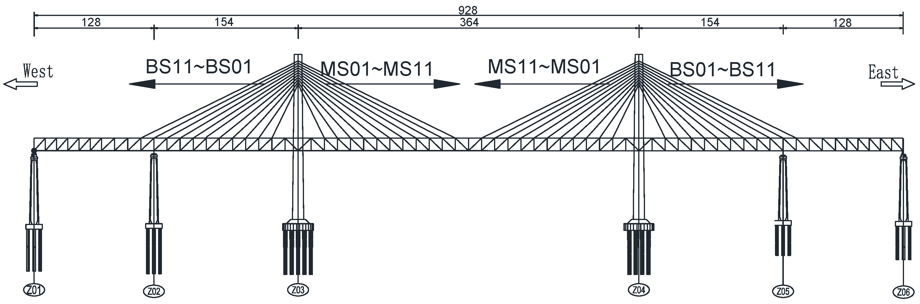
Figure 2.
Displacements of the Main Girder at the Cantilever End.
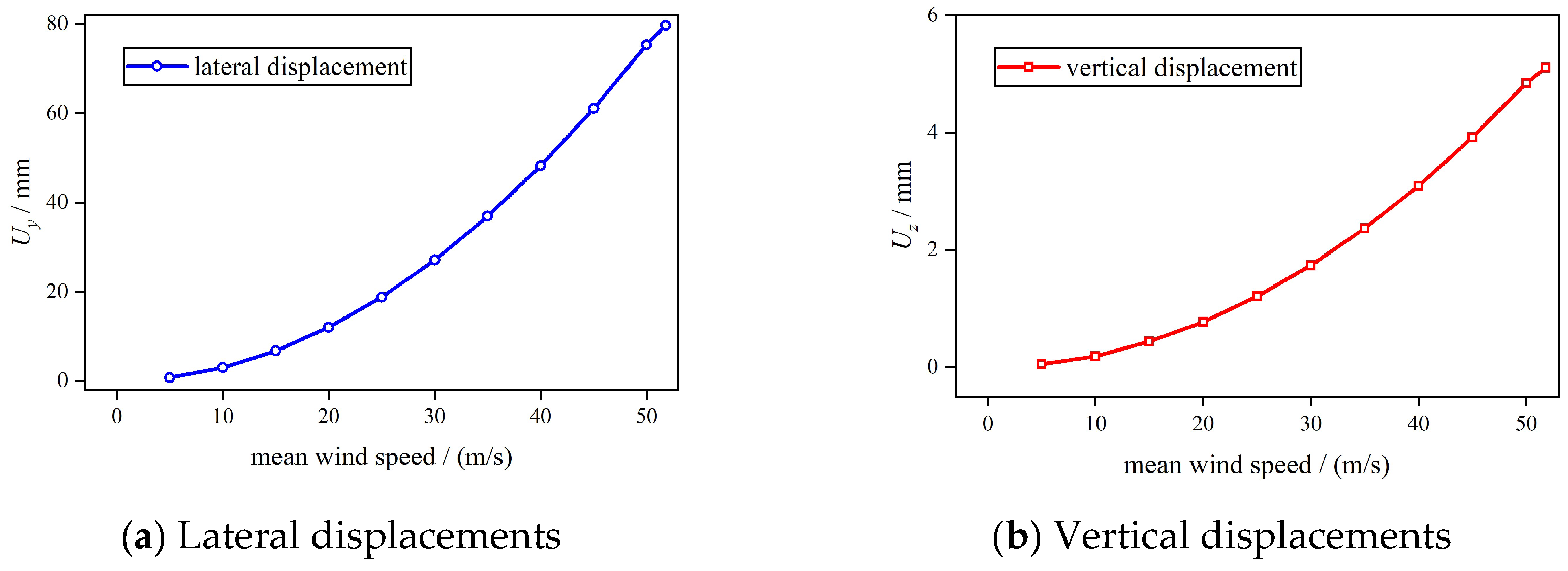
Figure 3.
Cable Force under Different Wind Speeds.
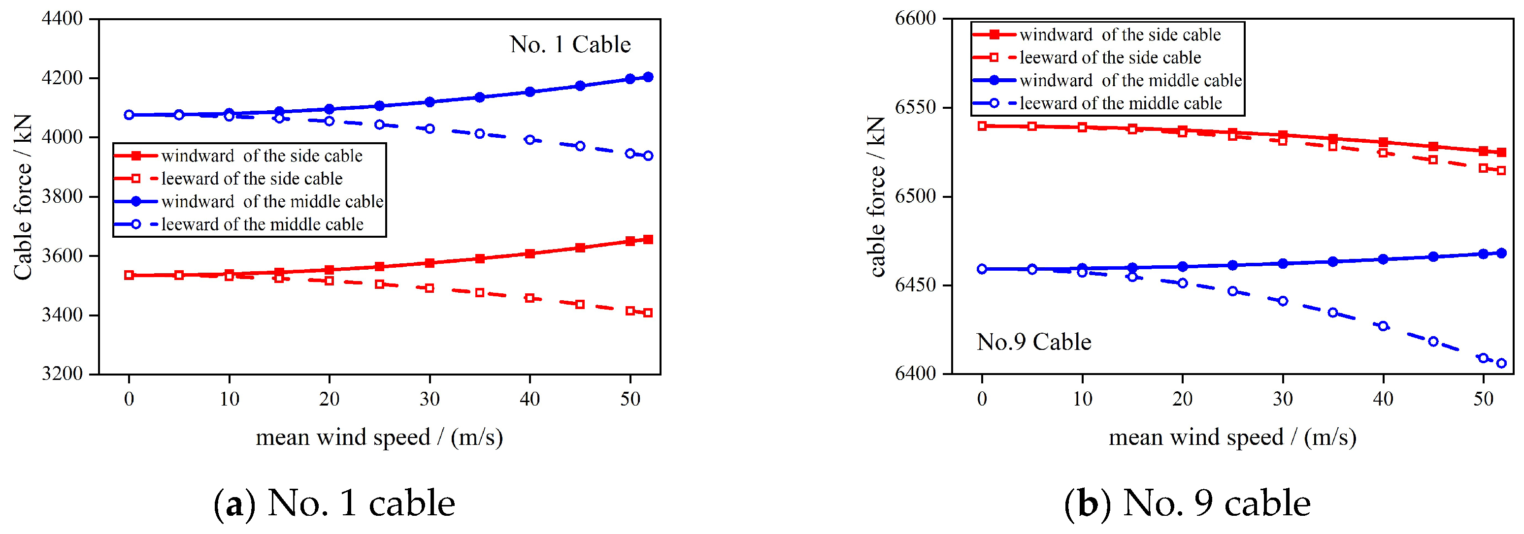
Figure 4.
Sectional Aerodynamic Derivatives.
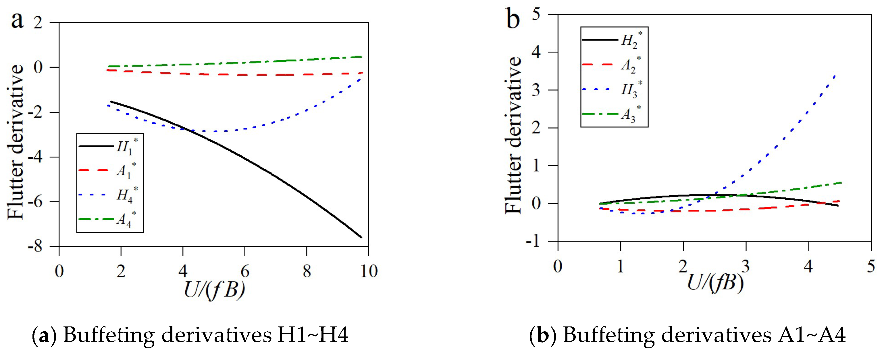
Figure 5.
Changing Rule of the Turbulence Intensity and the Turbulence Integral Scale along with the Average Wind Speed.
Figure 5.
Changing Rule of the Turbulence Intensity and the Turbulence Integral Scale along with the Average Wind Speed.
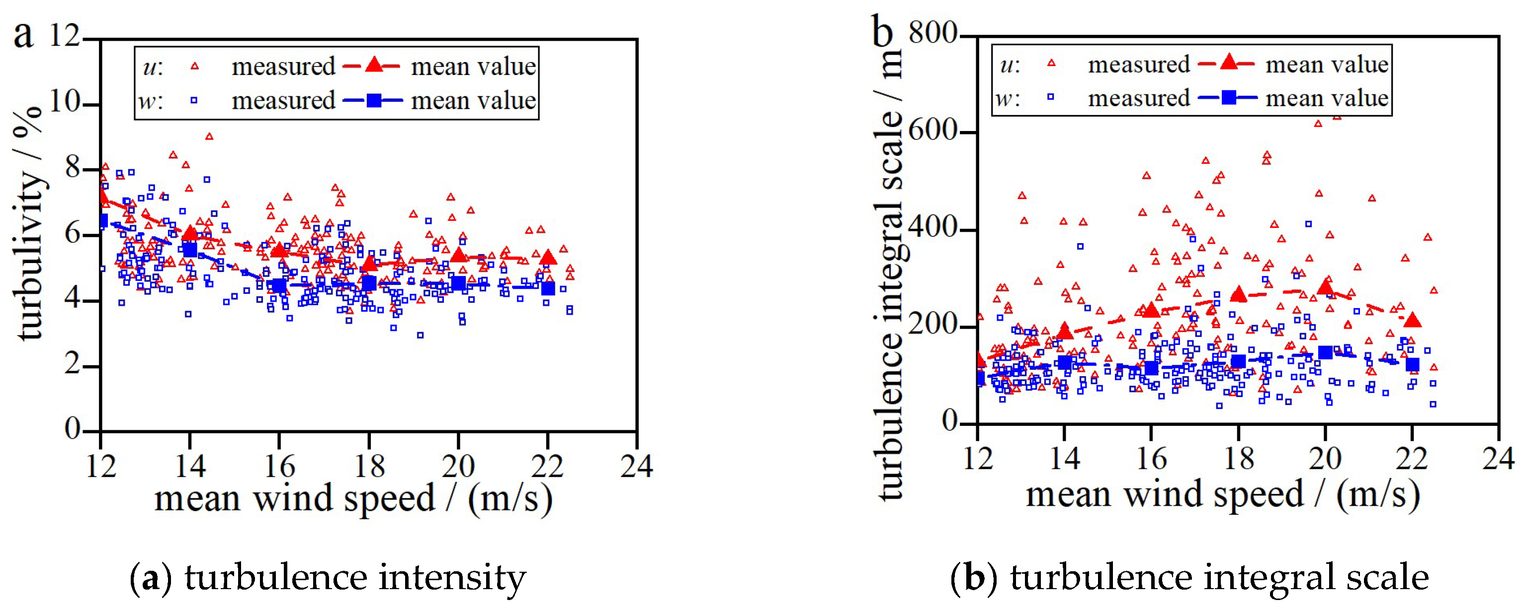
Figure 6.
Comparison between Measured and Numerical Values of Buffeting Response under Scenario 1 and Scenario 2.
Figure 6.
Comparison between Measured and Numerical Values of Buffeting Response under Scenario 1 and Scenario 2.
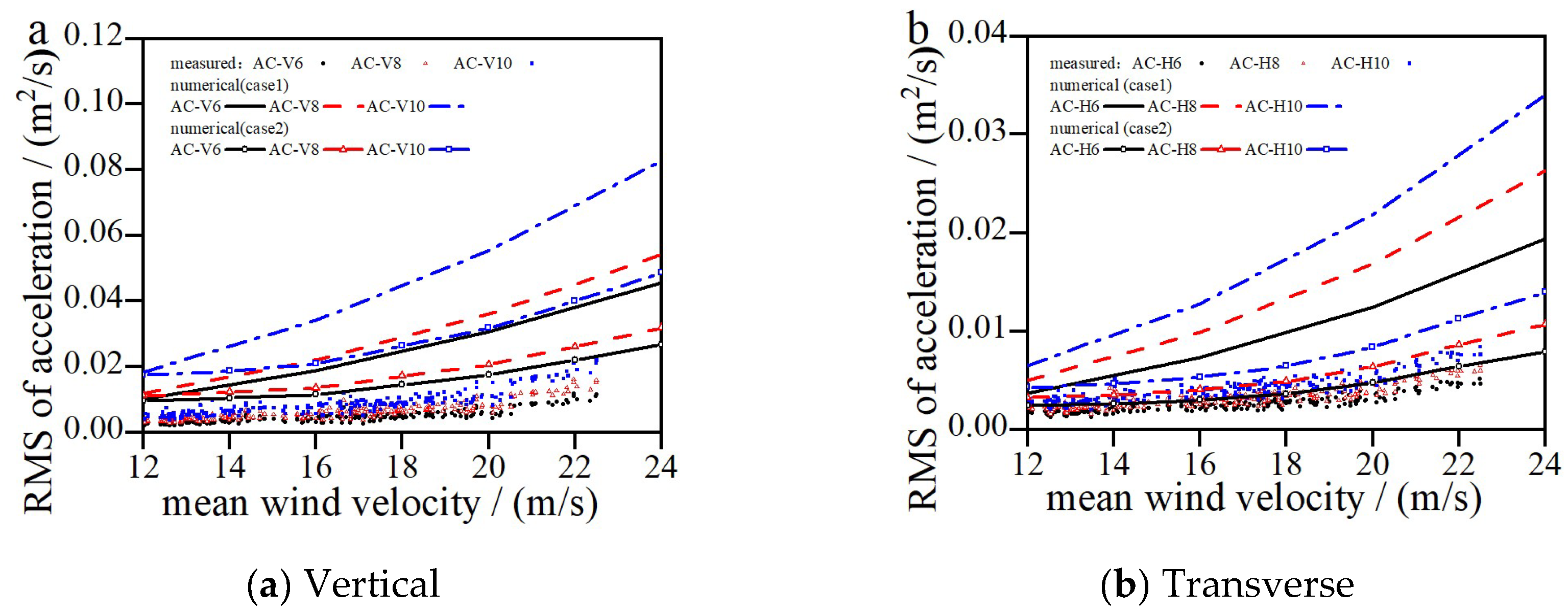
Figure 7.
Comparison between Measured and Predicted Values of Buffeting Response under Scenario 2 and Scenario 3.
Figure 7.
Comparison between Measured and Predicted Values of Buffeting Response under Scenario 2 and Scenario 3.
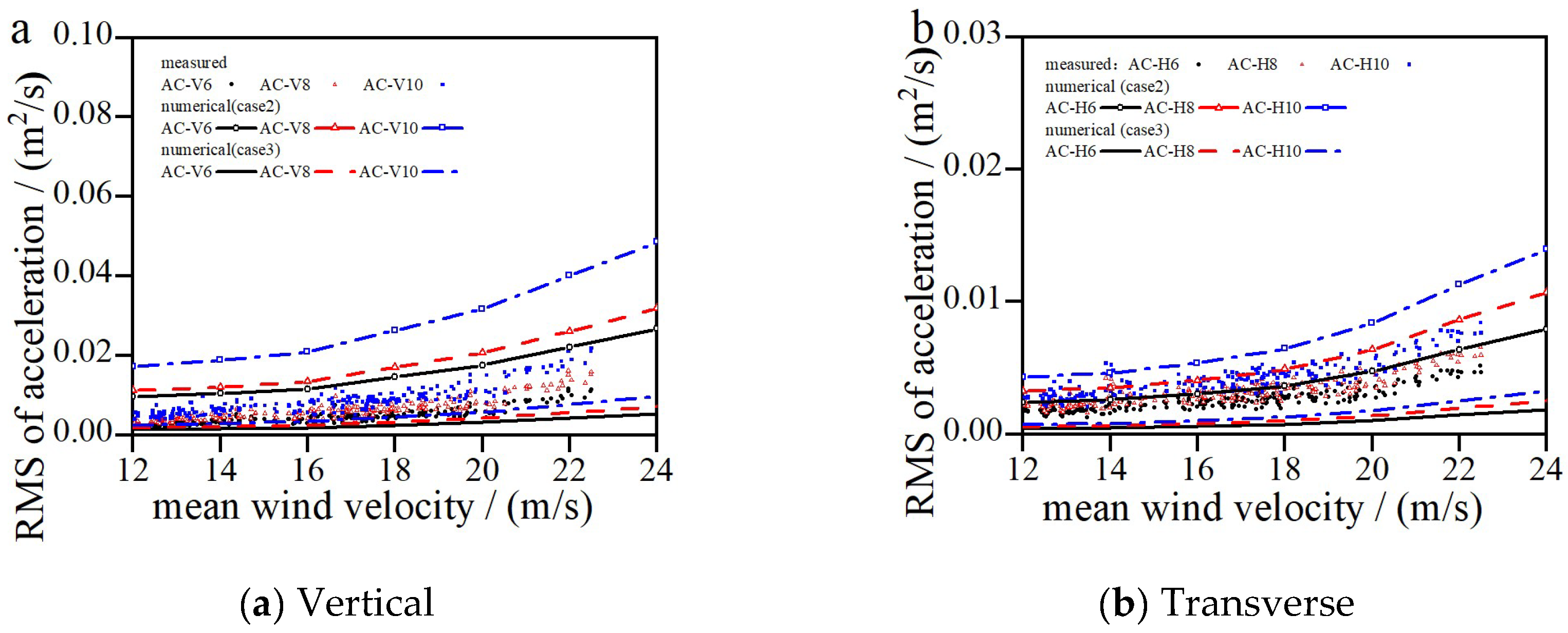
Figure 8.
RMS of the Transverse Buffeting Response of the Main Girder.
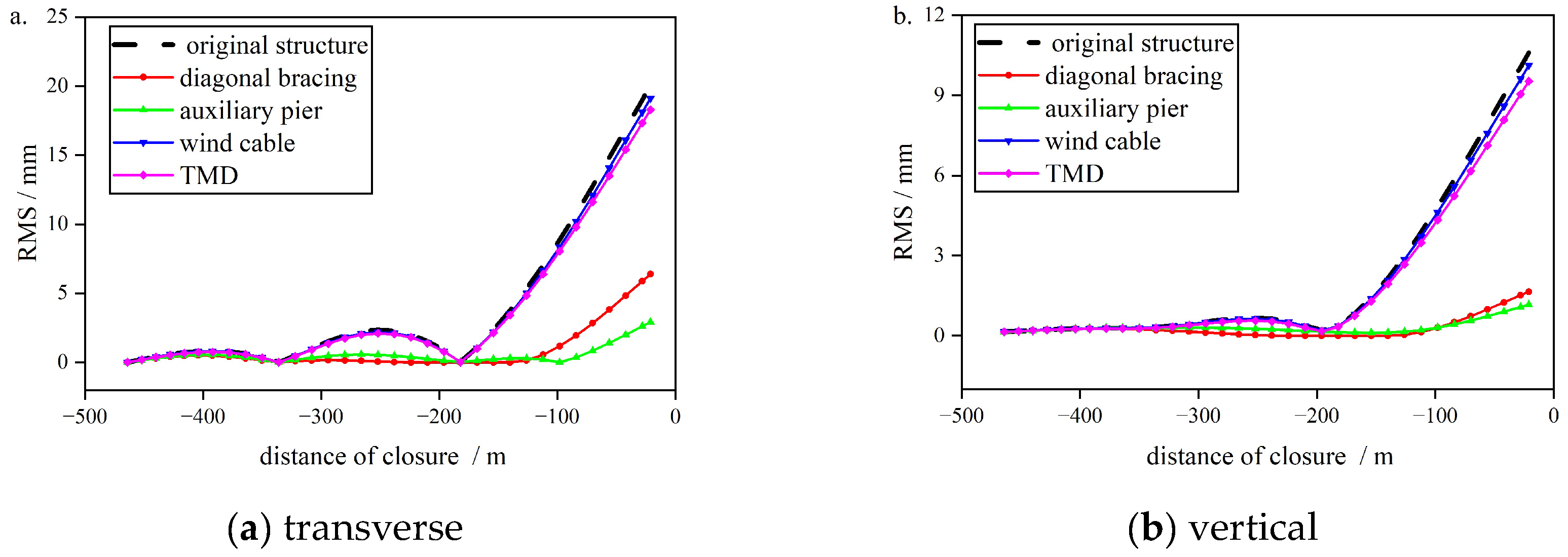

Table 1.
Material Property and Unit Types of Finite Element Model.
| Component | Density / (kg.m-3) | Elasticity modulus / MPa | Poisson’s ratio | Unit |
| Main girder | 9027.5 | 2.06×10⁵ | 0.3 | BEAM188 |
| Bridge tower | 2625 | 3.45×10⁴ | 0.2 | BEAM188 |
| Stayed cable | 7850 | 1.95×10⁵ | 0.3 | LINK10 |
| Concrete deck slab | 2625 | 3.55×10⁴ | 0.3 | SHELL63 |
| Steel deck slab | 7850 | 2.06×10⁵ | 0.3 | SHELL63 |
| Rigid cross girder | 0 | 1.0×10⁹ | 0.3 | BEAM4 |
Table 2.
Dynamic Characteristic Analysis of the Guyu Gate Channel Bridge.
| Mode | Frequency/Hz | Mode of vibration |
| 1 | 0.477 | Lateral bending of the bridge tower |
| 2 | 0.478 | First-order vertical bending of the main girder |
| 3 | 0.546 | First-order lateral bending of the main girder |
| 4 | 0.877 | Second-order vertical bending of the main girder |
| 5 | 1.013 | Lateral bending of the side span |
| 6 | 1.102 | First-order torsion of the main girder |
Table 3.
Static Wind Displacement of the Main Section (mm).
| Section location |
Longitudinal displacement |
Vertical displacement |
Lateral displacement |
| Mid-span cantilever end | -0.1 | 5.1 | 79.7 |
| Tower top on the windward side | 3.0 | -0.0 | 68.7 |
| Tower top on the leeward side | 0 | 0.5 | 68.6 |
Table 4.
Comparison between Stayed-cable Tensions and Calculated Results (Kn).
| Location | BS09 | MS09 | ||
| Measured values | Calculated values | Measured values | Calculated values | |
| Windward side | 6481 | 6536.1 | 6458 | 6461.4 |
| Leeward side | 6314 | 6533.8 | 6157 | 6446.8 |
Table 5.
Buffeting Analysis Scenarios.
| Scenario | Turbulence parameters | Aerodynamic admittance of the main girder |
| 1 | Wind spectrum, turbulence intensity, and turbulence integral scale specified in JTG/T 3360-01Specification | Unit function |
| 2 | Von Karman spectrum along with measured turbulence intensity and turbulence integral scale | Unit function |
| 3 | Von Karman spectrum along with measured turbulence intensity and turbulence integral scale | Sears function |
Table 6.
This is a table. Tables should be placed in the main text near to the first time they are cited.
Table 6.
This is a table. Tables should be placed in the main text near to the first time they are cited.
| Scenario | Vibration-restraining Measures |
| 1 | Original structure (without measure) |
| 2 | Inclined strut |
| 3 | Temporary pier |
| 4 | Wind-resistant cable |
| 5 | TMD |
Table 7.
Efficiency of Wind-resistant Damping Measures in the Maximum Cantilever State.
| Condition | RMS transverse/mm | η/% | RMS vertical /mm | η/% |
| 1 | 10.6 | 20.1 | ||
| 2 | 1.6 | 84.5 | 6.4 | 68.2 |
| 3 | 1.2 | 89.0 | 3.0 | 85.5 |
| 4 | 10.1 | 4.4 | 19.1 | 4.7 |
| 5 | 9.5 | 10.1 | 18.3 | 8.9 |
Disclaimer/Publisher’s Note: The statements, opinions and data contained in all publications are solely those of the individual author(s) and contributor(s) and not of MDPI and/or the editor(s). MDPI and/or the editor(s) disclaim responsibility for any injury to people or property resulting from any ideas, methods, instructions or products referred to in the content. |
© 2025 by the authors. Licensee MDPI, Basel, Switzerland. This article is an open access article distributed under the terms and conditions of the Creative Commons Attribution (CC BY) license (http://creativecommons.org/licenses/by/4.0/).
Copyright: This open access article is published under a Creative Commons CC BY 4.0 license, which permit the free download, distribution, and reuse, provided that the author and preprint are cited in any reuse.


