
Submitted:
13 January 2026
Posted:
15 January 2026
You are already at the latest version
Abstract
Numerous studies show that the use of dental guides that rest on the patient's teeth improves the precision of implant placement, but the currently developed procedures and selected materials are still not perfect and could result in deviations from the planned implant position. The impact of the surgeon's hand force on the deformation of dental guides during implant placement has not yet been investigated or documented. In this study the behavior of the 3D guide model is evaluated by FEA analysis to validate the influence of the force of the surgical hand on dental guides due to their application. FEM simulation of deformation and stress was designed for four different types of dental guides that are supported on teeth for different ways of supporting the guide due to the action of the surgeon's manual force (chosen arbitrarily 30 N). The finite element simulation method performed on 5 sets of commonly used biocompatible polymer materials, Stratasys MED610 and VeroGlaze MED620, EOS PA2200, Formlabs FLSGAM01 and Stratasys ULTEM 1010, successfully numerically quantified the deformation of the dental guide caused by the surgeon's arbitrarily manual forces during manipulation. Based on the conducted analyses, guidelines were proposed for improving the design of guides, with an emphasis on optimal selection of supports, stability on the patient's anatomy, and reduction of deformations, thereby increasing the accuracy of implant placement. It was found for all four designs of dental guides that the deflection depends on the size of the arm, i.e. the distance of the support from the point of application of the force. As a result of the study, diagrams were created that serve as guidelines for the design of beam (A and A1) and cantilever (B and B1) versions of dental guides that rely on teeth. Guidelines for enhancing guide design were put out based on the analyses that were carried out, with a focus on the best choice of supports, stability on the patient's anatomy, and minimization of deformations in order to improve implant placement accuracy.
Keywords:
dental guides
; deformation
; deflection
; FEA analysis
; beam type
; cantilever type
; accuracy
1. Introduction
This scientific study aims to investigate and simulate the design of a dentally supported guide for dental implant insertion using the finite element method (FEM).
Finite element analysis (FEA), which is widely used in medical and dental applications, is performed on complete 3D models of the jaw and teeth generated using intraoral scanners (IOS), facial scanners, and cone-beam computed tomography (CBCT). The accuracy of these input data directly affects the reliability of implant position predictions. In recent years, digital dentistry has become a part of the daily practice of dentists. From a surgical perspective, immediate implant insertion is much more difficult than implant placement in a healed ridge. Implant surgery is a common method to help oral surgeons manage these criteria for challenging procedures and situations, supported by computer-aided technology or customized and printed guidelines. An ideal three-dimensional (3D) implant position can be virtually prepared within a surgical planning software program with the aid of cone beam computed tomography (CBCT) and digital intra-oral imaging. Dental implant insertion using static guided surgery is a well-researched process that calls for the production of a custom surgical guide as well as hardware and software support tools. A series of different guides could be used to direct the surgical drills during implant bed preparation.
The most recent procedures and surgical techniques in the field are covered in mastering implant prosthetics through a multidisciplinary approach [1], as is the computer-assisted matching of planning and execution in orthopedic surgery with the goal of identifying and utilizing a multidisciplinary protocol for the precise placement of implants [2]. This area of surgery involves several difficulties and challenges, including the correction of malpositioned implants through periodontal surgery and prosthetic rehabilitation [3,4], and the optimal placement of osseointegrated implants [5]. A comparison of computer-assisted tomography and data-gathering modalities in prosthodontics [6,7], a surgical placement guide for use with osseointegrated implants [8], the display of three-dimensional anatomy with stereolithographic models [9], computer-assisted matching of planning and execution in orthopedic surgery and guides [10,19], and three-dimensional computer graphics for craniofacial surgical planning and evaluation are just a few cities that describe the accuracy of various forms of computer-aided design. The authors of other studies focused more on implant placement accuracy, such as the accuracy of implant placement using a stereolithographic surgical guide [11,12,20,21,22,23,29,30,36,37,55,56,65,68,69,70,71,74,80]. Applications of medical rapid prototyping assisted customized surgical guides in complex surgeries [14,15,16,17], the impact of experience on dental implant placement, and dynamic navigation approaches [24] have all been extensively documented in numerous works [13,17,18,38,39,53,57]. The accuracy of various computer-aided design/computer-aided manufacturing surgical guides for dental implant placement in works [25,26,27,28,29] and reproducibility of the drilling access of digitalized surgical guides generated via three different implant planning software programs were published in the study.
Additionally, Ketcha M.D., et al. highlights how fundamental restrictions impact image registration performance, detailing the implications of image noise and resolution in CT-guided interventions [31], while studies [32,33] demonstrate the impact of CT parameters on STL model accuracy and quick prototyping. In [34], a comparison between intraoral scanning and traditional imprint procedures using 3-dimensional superimposition is highlighted. The accuracy of chairside-milled CAD/CAM drill guides for dental implants is described by Kuo R.F. et al. in [35], comparisons between models of traditional intraoral casting and digital rapid prototyping are described in [37], and the impact of freehand, pilot-guided, and fully guided surgical protocols on the accuracy of immediately placed implants was published in [40]. Analyses of accuracy and efficacy in guided surgery can be found in [41,42,43,44,45,46,47], MRI and CBCT image registration in works [48,49,50,51], comparative evaluations of intraoral and extraoral digital impressions in [52,54,55], computing and computer-assisted intervention [56,57,58,59,60,61,62,63,64] and modeling accuracy in dental surgical guide fabrication using different 3-D printing techniques can be found in [66].
In order to facilitate the transfer of the surgical plan from the computer to the operating room, the Tooth-Supported 3D-Printed Surgical Guide should be created and manufactured to suit the tissue and precisely match the patient's anatomy. The guides' primary function is to offer prearranged routes for drilling or cutting during surgery as well as for the implant's directed (guided) attachment.
The use of dental guides increases the accuracy of implant placement, according to studies in the field of dental medicine [20,21,22,23,24,25]. However, the already created processes are still not ideal, and deviations from the planned ones happen. Significant differences between the intended and actual implant sites have also been discovered in commercial devices, according to a review [21].
Because it affects the direction and position of the drill bit, deformation of the guides caused by the surgeon's hand forces during implant placement may have negative effects on the patient. More thorough research on the impact of the surgeon on the dental guides in terms of deforming the dental guides during application (surgery) has not been found in the literature, despite studies showing the impact of the clinician's experience on the accuracy of implant placement [43,44,45].
Implant placement errors using guides with a single free end (cantilever form) have been studied scientifically in work [69]. Implants positioned using guides with free ends frequently vary more from the intended position than those with a support at the end, according to research [70,71,72,73]. Movement is thought to happen while drilling [74]. According to research [75], selecting a material that is as hard as feasible may help prevent the guide's free end from moving.
Static guided implant surgery (sGIS) accuracy may be compromised by a distal free-end scenario, which could lead to inadequate deformation (stability) of the surgical guide. This study looked into how the surgeon's manual forces during implant insertion affected the guides' deformation.
Studies defining the impact of the clinician on dental guides during surgery, i.e., whether deformation (deflection) occurs due to the cantilever geometry of the guide when drilling at greater distances from a solid support (larger arm), are not currently available in the literature (perhaps they are now, but not for this type of guide). Implant positioning and placement may be incorrect if the surgeon manipulates and holds the dental guide excessively during surgery.
The objective of the study is to produce dependency diagrams that illustrate the link between the guide's deflection (deformation) and the force's distance from the support. This information offers parameters for the construction of guides that indicate how far away from the support the drilling position, or holding it by hand, can be so that the guide's deformation is acceptable, insignificant, or so little as to be ignored.
The current study aims to:
(i) Determine the impact of the surgical hand's force on dental guides as a result of their application using a numerical model.
(ii) Make recommendations for enhancing dental guide design while considering the relevant factors and the outcomes of the applied experiment.
The following is the anticipated scientific contribution of the work:
(1) Improving dental guide design by establishing standards for improving "cantilever" and "beam – like" dental guide design to enhance their stability and fit on the patient’s dentition.
(2) Deformation and stress diagrams for four distinct dental guide designs (types) that are currently most frequently used in practice.
2. Materials and Methods
In this part, authors describe the methodology of the study, detailing the procedures employed to allow readers to assess its validity and reliability. This section specifies the type of study conducted, the data collection methods, and the approaches used for data analysis. To simulate the expected structural behavior of dental guides under forces applied by the surgeon’s hand, the study outlines the guide designs and materials used. The rationale for selecting these methods, materials, and specific dental types or versions is also provided. The research design frequently focuses on applied research with the aim of developing 3D design and printing techniques, prototyping, and providing suggestions for improving dental guide construction while taking the surgeon's preferred force for implant placement into consideration. In connection to the choice of design type, particularly the type of guide arms, the authors sought to advance scientific understanding and facilitate the resolution of the practical problem of bending and deforming dental guide templates. The main objective of applied deductive research is to test theories. However, the focus of this case study research is on demonstrating a new and simpler method for lowering risk in dental guides at the implementation stage, based on the examination and use of earlier applied numerical simulation.
This study presents two equal hypotheses: (1) The clinician's (surgeon's) influence, i.e., the deformation of the dental guide during manipulation and application during surgery, can be quantified by numerical simulation using the finite element method (FEM); and (2) It is possible to suggest guidelines for the improvement (advancement) of dental guide design with regard to the influence of the surgeon force.
The notion is predicated on the possibility of quantifying the surgeon's impact on the dental guides during application. The impact of the surgeon on the dental guides during application was investigated quantitatively using the finite element technique (FEM) in order to support or contradict the idea.
The occurrence of deformation and stress in dental guides during application is ascertained by employing FEM numerical tools to simulate the action of manual force during surgery. The simulation's objective is to produce diagrams that illustrate the connection between guide deflection and the force application point's distance from the support. This information offers parameters for the design of guides that indicate the maximum distance that the drilling position, or hand grip, can be from the support while guaranteeing that guide deformation at the free end is acceptable.
The initial phase involves creating the experimental setup and designing the dental guides. A numerical model is produced in the Comsol Multiphysics software package (version 4.3, Comsol Inc., Sweden). Boundary conditions are altered for the numerical model, and the deflection results are calculated numerically. Ultimately, diagrams are produced that illustrate how the force exerted on the dental guide's free end varies with arm length, or the distance from the support.
3.1. Dental Guide Design
This section of the study will use 3D modeling to present the design of several dental guide types and potential alterations. The authors will demonstrate their contribution by displaying four dental guide designs using two types of guide suspensions and two instances of potential iteration versions placed on a patient's jaw model after first showcasing an example of a produced guide type from the cited published work [69].
In present study examined guides that use teeth for support authors divided into two groups (Figure 1) according to works [69,76,77]:
• cantilever – guides that rely on only one side of the patient’s anatomy (teeth) and have one free end
• beam – guides that rely on both ends of the patient’s jaw anatomy.
For the purpose of researching the influence of the surgeon's manual force on dental guides, authors created four different designs of dental guides versions in the 3D software package (Figure 2). The names of the variations are:
• version A – beam-type guide for full dentition with all surfaces on the teeth included. Support is provided on the last two molars (occlusion).
• version A1 – beam-type guide for full dentition with occlusal surfaces on the teeth removed. Support is provided on the last two molars.
• version B – cantilever-type guide for full dentition with all surfaces on the teeth included. Support is provided on half of the dental arch.
• version B1 – cantilever-type guide for full dentition with occlusal surfaces on the teeth removed. Support is provided on half of the dental arch.
For each of the four guideway designs, a finite element mesh was produced in the Comsol Multiphysics software program based on the guideways' 3D model (Figure 2). Three-dimensional linear tetrahedral elements make up the finite element mesh. In order to apply boundary conditions (supports and forces) to the 3D models of the guideways, sufficient surfaces were supplied (modeled). The produced finite element mesh is displayed in Figure 3. The surfaces ready to define the force (load) boundary conditions are indicated by red, while the surfaces ready to determine the displacement boundary conditions are indicated by blue. More information about applied boundary conditions as initial data for dental model will appear in chapter 3.2. The fundamental information for the produced finite element meshes is listed in Table 1.
3.1. Materials
The chosen material must be defined in order to create a numerical model. Five commercially available biocompatible polymer materials that are generally used to make dental or surgical guides (orthopedics) were the subject of simulations. These materials include Formlabs FLSGAM01, EOS PA2200, Stratasys ULTEM 1010, VeroGlaze MED620, and Stratasys MED610.
3.1.1. MED610 (Stratasys)
The Polyjet technique is used to create a translucent, stiff dental resin with a high level of dimensional stability. Printing dental guidelines and creating partial dentures are its main uses [14].
3.1.2. VeroGlaze MED620 (Stratasys)
VeroGlaze MED620 is a stiff, opaque dental resin that is biocompatible and has excellent dimensional stability and precision. designed to print dental models. The Polyjet process makes use of it. mechanical characteristics that are marginally inferior to MED610 [14].
3.1.3. PA2200 (EOS)
Polyamide 12 is the foundation of PA2200 Carbon Reduced. It is meant to be processed by selective laser sintering, or SLS. It is distinguished by whiskey with varying levels of stiffness and isotropic strength. A layer thickness of 100 µm yields very good surface quality and detail resolution along with fine resolution. Production equipment such as grippers, templates, and holders; surgical cutting guides and bone models for the medical industry; glasses in the consumer goods industry; spare parts like brackets or covers, such as in the automotive industry; and functional parts for prototyping, such as hinges or threads, are some of its applications [15].
3.1.4. FLSGAM01 (Formlabs)
This material is a biocompatible polymer that may be autoclaved and used to create dental guides, dental drill guides, pilot drill guides, and device sizing templates that surpass dental criteria in terms of precision, part quality, and performance. Its original purpose was to process SLA (stereolithography). It satisfies all biocompatibility risk requirements and is certified in accordance with ISO 10993-1:2018, Biological evaluation of medical devices - Part 1: Evaluation and testing within a risk management process, and ISO 7405:2009/(R)2015, Dentistry - Evaluation of biocompatibility of medical devices used in dentistry [16].
3.1.5. ULTEM 1010 (Stratasys)
High-performance polyetherimide (PEI) thermoplastic ULTEM 1010 was created for fused deposition modeling (FDM) processes. It possesses outstanding thermal stability, a wide range of chemical resistance, and a high tensile strength. Because of its great heat resistance, it may be autoclaved for uses including tooling and sterilization. Both ordinary and certified grade (CG) versions of this material are available. The substance can be utilized in food and medical applications because it is biocompatible.
Reference research was used to choose and determine all of the material attributes employed in the simulations [14,15,16,17]. In cases where a range of elastic modulus values is reported, the lower bound of the modulus was selected for numerical modeling to provide conservative deformation estimates.

| Modulus of elasticity | Poisson's ratio | Density | |
| LABEL | E [ MPa ] | ν [ - ] | ρ [ kg/m3 ] |
| MED610 | 2000 - 3000 | 0.3 | 1170 |
| MED620 | 2300 - 3300 | 0.31 | 1170 |
| PA2200 | 1700 | 0.38 | 930 |
| FLSGAM01 | 2900 | 0.35 | 1090 |
| ULTEM1010 | 3040 | 0.44 | 1270 |
3.2. Boundary conditions
Lastly, the loading and displacement boundary conditions applied to the model of the dental guides are defined by the numerical algorithm settings. On the surfaces designated for this purpose, the displacement boundary conditions are modeled as fixed constraints as shown in the computer sketch in Figure 4.
The load boundary conditions are represented as an absolute force acting in a certain direction (Figure 5).
Four numerical models were thus produced, one for each dental guide design. The numerical model included geometric nonlinearity to account for large deformations. The applied load represents a worst-case surgical handling scenario, intentionally selected to evaluate the upper-bound deformation behavior of the guides.
Three tree group of factors were changed in the simulations: the selected materials, the load boundary conditions (force direction), and the displacement boundary conditions (support positions). When adjusting the supports, the force application arm is lowered and supports are progressively added, one tooth at a time. The starting clamping position is always at the place furthest from the point of force application (Figure 8). The force is always applied to the guide's free end. On every surface the tooth sits on, a displacement boundary condition (clamping) can be established. The principle of sequentially adding displacement (clamping) boundary conditions on a type B tooth guide is presented in Figure 6 and displacement (clamping) boundary conditions on a type A tooth guide is presented in Figure 7.
The force's direction is altered when specifying the load's boundary conditions. The surgeon's force was chosen to be always the same, estimated arbitrarily at a value of 30 N. Since the surgeon often holds the guides, the manual holding force (30 N) is several times more than the cutting force at high speeds (from 0.5 to a maximum of 2 N), as stated in works [67,68]. The amount of force was selected based on published study [56].
The computations were carried out for a force acting in the positive direction of the x and y axes of the Cartesian coordinate system and in the negative direction of the z axis (Figure 8). The computation is straightforward when the force is applied in the positive direction of the z-axis, as this causes separation of the dental guide from the patient’s dentition. The displacements and stresses for the case where the force is directed in the negative direction of the x axis were not calculated because they are very similar to the case where the force is directed in the positive direction of the x axis. The outcomes are the same whether the force is applied in the positive direction of the y axis since, in theory, we can talk about symmetry when the force is directed in the negative direction of the y axis. Thus, in this instance, a stress and strain study was not carried out. Four numerical models—that is, all four possible dental guide designs and five different biocompatible materials that can be utilized to manufacture dental guides—were subjected to the outlined principles of altering the boundary conditions of displacements and loads.
Figure 8.
Principle of adding boundary conditions of loads (forces) on a dental guide of type A. The force is directed in the negative direction of the z axis (blue arrow) or in the positive direction of the x (red arrow) or y axes (green arrow).
Figure 8.
Principle of adding boundary conditions of loads (forces) on a dental guide of type A. The force is directed in the negative direction of the z axis (blue arrow) or in the positive direction of the x (red arrow) or y axes (green arrow).
3. Results
The results of the dependence of the displacement on position of the support and the dependence of the stress on position of the support were obtained following the numerical analysis. The FEM simulations were performed for each material and each guide design. For clarity and comparability, the results presented in the diagrams represent the averaged values obtained across all five investigated materials. The plotted data therefore show the mean displacement and stress values, accompanied by the corresponding standard deviations, which reflect the variability arising from differences in material mechanical properties. For each of the four guide designs, eight different support configurations were simulated under three loading directions using five selected biocompatible materials, resulting in a total of 480 numerical simulations.
The displacements and stresses that can be anticipated at the dental guide's free end for a specific distance (number of teeth) from the closest support are depicted in the diagrams. Because it accounts for displacements in all three dimensions (u, v, and w) and stresses in accordance with von Mises (HMH theory), the "Total displacement" choice was chosen for the displacement, which is always the largest. The diagrams display the position of the teeth in the jaw on the abscissa and displacements on the ordinate. The results of the total displacement for the three directions of force action (positive x, positive y, and negative z) are summarized below the abscissa. Figure 9 shows a graphical representation of the average displacement distribution of the dental guide type B due to the force of the surgeon's hand in the direction of the "-z" axis. The largest value is logically on the longest arm, i.e. on the 7th tooth, and amounts to 5,40 mm. Figure 10 shows a graphical representation of the displacement of the dental guide type B1 and the maximal displacement is calculated as 13.06 mm. Figure 11 refers to the displacement in dental type A where the maximal amount of displacement is calculated as 1.01 mm. And last Figure 12 refers to the average displacement distribution in dental type A1 with maximal calculated value of 2.84 mm. With the largest calculated deviation of 1.01 millimeters at the seventh tooth and half as much, or an average deviation of 0.51 millimeters, at the position of the sixth tooth, it is clearly clear from the presented simulations that using dental guide type A is the most advantageous scenario.
By varying the input parameters, the authors identified and presented an additional important dataset obtained from the numerical simulations, namely the stress distribution within the guide material, expressed in MPa. This information is particularly relevant, as it contributes to the broader discussion on materials used for dental guides, their mechanical behavior, deformation and deflection characteristics, and the potential for improving guide architecture through the selection of materials with more suitable mechanical properties. The obtained stress results therefore provide further insight into material performance and support the optimization of dental guide design.
Figure 13 shows a graphical representation of the average stress distribution of the dental guide type B due to the force of the surgeon's hand in the direction of the "-z" axis. The largest value is logically on the longest gripping arm, i.e. on the 7th tooth, and amounts to 164,63 MPa. Figure 14 shows a graphical representation of the stress of the dental guide type B1 and the maximal stress is calculated as 143.68 MPa. Figure 15 refers to the stress in dental type A where the maximal amount of stress is calculated as 30.29 MPa. And last Figure 16 refers to the average stress distribution in dental type A1 with maximal calculated value of 58.32 MPa. With the lowers calculated stress of 30.29 MPa at the seventh tooth with almost the same value of stress at the position of the sixth tooth, it is clearly clear from the presented stress simulations that using dental guide type A is the also most advantageous scenario.
4. Discussion
The following conclusions can be drawn from the average displacement distribution and average stress distribution simulation data that have been presented:
• In all four dental guide designs, the deflection is determined by the arm's size, or the predicted distance between the support and the force application point. Rating: acceptable.
• Because the dental guide's cross-section is smaller in designs A1 and B1 (protruded occlusal surface), the displacements are naturally greater. Rating: acceptable.
• For all dental guide designs, the greatest displacements are frequently found in the z-axis direction and can even be several times greater than those in the x- and y-axes. Rating: acceptable.
• The stresses in dental guides with designs A and A1 are largely constant and far less than the material's tensile strength. There are abrupt changes in the cross-sectional area as a result of the notch action at the locations where two teeth come into contact, but these changes are confined and affect a very limited region. Rating: acceptable.
• With the exception of the broad arms, the strains in designs B and B1 are likewise largely constant. The incisor region's smaller cross-sectional area may also help to explain this. Rating: acceptable.
• All four dental guide designs have stresses that are generally within acceptable bounds.
It is clear that the displacement and stress diagrams offer sufficient information for choosing and developing dental guide support. Comparing the results of the simulations in published studies [21,44,80], similar conclusions are reached that the dimensions, shape and support of dental guides can statistically significantly affect the accuracy of implant placement. The size of the arms at the free end of dental guides in order to maintain acceptable displacements has been determined by this study using quantifiable, verifiable, and concrete data.
The hypothesis was validated based on the outcomes of the defined approach and the application of numerical analysis. The dental guide's deformation brought on by the surgeon's manual forces during manipulation was effectively measured using the finite element simulation method. Guidelines for enhancing guide design were put out based on the analyses that were carried out, with a focus on the best choice of supports, stability on the patient's anatomy, and minimization of deformations in order to improve implant placement accuracy.
5. Conclusions
The impact of the surgeon's handling of dental guides during surgery was investigated in this study. A computational model that altered the displacement and load boundary conditions was used to describe the surgeon's influence. It was discovered that if the guide shape is such that it has an excessively big arm at the free end without support, the surgeon can significantly affect the deformation of the dental guide. Diagrams that serve as guidance for the design of beam (A and A1) and cantilever (B and B1) versions of dental guides that rely on teeth were produced as a consequence of the study.
In particular, the size of the arm—that is, the distance between the support and the force application point—determines the deflection for each of the four dental guide designs. The z-axis direction is where the biggest displacements happen most frequently, and they can even be many times larger than the x- and y-axis displacements.
When the guide is symmetrically supported on the teeth in positions four, three, two, or one, it is advised to take a maximum of six teeth between the two supports for version A. According to the results, the force applied to the teeth at position three causes displacements (deformations) that are extremely near to zero (≈0.06 mm in the z-axis direction).
Due to the removal of the occlusal surfaces, the deflection values in the A1 version of the dental guide are much higher than those in the A version. It might be advised to utilize tooth number three's position as a limiting value for shaping, as the displacements then approach zero (≈0.09 mm in the z-axis direction).
Given that it is only supported on one side and it is not surprising that the cantilever version B of the guides has a greater deflection than the beam version. There should be no more than two "empty" spaces (without supports) between the drilling point and the support while shaping the guides, according to the figure illustrating the dependence of the displacement on the position of the support. In the direction of the z-axis, the deflection is then approximately 0.5 mm.
The displacement diagram in the B1 version indicates a maximum of two empty spaces without a support between the drilling point and the support; in other words, the support needs to be extremely near to the drilling point. In the z-axis direction, the deflection at two "empty" spaces (without supports) is around 0.8 mm.
Author Contributions
For research articles with several authors, a short paragraph specifying their individual contributions must be provided. The following statements should be used “Conceptualization, N.Š. and V.T.; methodology, N.Š. and V.T.; software, Z.K.; validation, N.Š. and J.H.; formal analysis, N.Š.; investigation, Z.K.; resources, Z.K.; data curation, Z.K. and N.Š.; writing—original draft preparation, N.Š. and Z.K.; writing—review and editing, N.Š. and V.T.; visualization, Z.K. and N.Š.; supervision, V.T.; project administration, N.Š.; funding acquisition, N.Š., Z.K. and V.T.
Funding
This scientific work was funded through an internal research project of the Karlovac University of Applied Sciences entitled: ADAM (Advanced Dental Anatomy Modeling).
Informed Consent Statement
Not applicable.
Data Availability Statement
All data related to this research can be obtained upon request. All materials are available on request from the corresponding authors.
Acknowledgments
During the preparation of this manuscript/study, the author(s) used finite element analysis (FEA) for the purposes of simulation. The authors have reviewed and edited the output and take full responsibility for the content of this publication.
Conflicts of Interest
The authors declare no conflicts of interest.
References
- Resnik, R. Misch's Contemporary Implant Dentistry, St. Louis, USA, Elsevier, 2020, 4th edition, February 20.
- de Avila E.D.; de Molon R.S.; de Barros-Filho L.A.B.; de Andrade M.F.; de Assis Mollo Jr. A; de Barros L.A.B. Correction of Malpositioned Implants through Periodontal Surgery and Prosthetic Rehabilitation Using Angled Abutment. Case Reports in Dentistry, 2014; DOI: 10.1155/2014/702630.
- Gehrke S.A. Correction of esthetic complications of a malpositioned implant: a case letter. The Journal of Oral Implantology. 2014; Vol. 40 (6); p.p. 737-743; DOI: 10.1563/AAID-JOI-D-12-00252.
- Kemper R.; Galmiklos A.; Aroca S. Surgical and prosthetic correction of malposed maxillary implants: a case report. The International Journal of Periodontics and Restorative Dentistry. 2013; Vol. 33 (5); p.p. 575-581; DOI: 10.11607/prd.1199.
- Engelman M.J.; Sorensen J.A.; Moy P. Optimum placement of osseintegrated implants. The Journal of Prosthetic Dentistry. 1988; Vol. 59 (4); p.p. 467-473; DOI: 10.1016/0022-3913(88)90044-3.
- Vannier M.W.; Marsh J.L.; Warren J.O. Three dimensional computer graphics for craniofacial surgical planning and evaluation. SIGGRAPH Computer Graphics. 1983; Vol. 17 (3); p.p. 263-273.
- McGivney G.; Haughton V.; Strandt J.; Eichholz J.; Lubar D. A comparison of computer–assisted tomography and data-gathering modalities in prosthodontics. The International Journal of Oral and Maxillofacial Implants. 1986; Vol 1 (1); p.p. 55-68.
- Edge M.J. Surgical placement guide for use with osseointegrated implants. The Journal of Prosthetic Dentistry. 1987; Vol. 57 (6); p.p. 719-731; DOI: 10.1016/0022-3913(87)90371-4 .
- Mankovich N.J.; Cheeseman A.M.; Stoker N.G. The display of three-dimensional anatomy with stereolithographic models. Journal of Digital Imaging. 1990; Vol 3 (3); p.p. 200-203; DOI: 10.1007/BF03167610.
- Radermacher K.; Staudte H.W.; Rau G. Computer assisted matching of planning and execution in orthopedic surgery. Engineering in Medicine and Biology Society, 1993. Proceedings of the 15th Annual International Conference of the IEEE. San Diego; CA; USA; p.p. 946-953.
- Sarment D.; Suković P.; Clinthorne N. Accuracy of implant placement with a stereolithographic surgical guide. The International Journal of Oral and Maxillofacial Implants; 2003; Vol. 18 (4); p.p. 571-578; https://pubmed.ncbi.nlm.nih.gov/12939011/.
- Al-Harbi S.A., Sun A.Y.T. Implant placement accuracy when using stereolithographic template as a surgical guide: preliminary results. Implant Dentistry; 2009; Vol. 18 (1); p.p. 46-56; DOI: 10.1097/ID.0b013e31818c6a50.
- Tetsworth K.; Block S.; Glatt V. Putting 3D modelling and 3D printing into practice: virtual surgery and preoperative planning to reconstruct complex post-traumatic skeletal deformities and defects. PabMed Journal; 2017; doi: 10.1051/sicotj/2016043.
- Araujo-Corchado E.; Pardal-Peláez B. Computer-Guided Surgery for Dental Implant Placement: A Systematic Review. Prosthesis; 2022; Vol. 4 (4); p.p. 540–553; doi. [CrossRef]
- Dahake S.W.; Kuthe A.; Mawale M.B.; Bagde A.D. . Applications of medical rapid prototyping assisted customized surgical guides in complex surgeries. Rapid Prototyping Journal. 2016; Vol. 22 (6); p.p. 934-946. [CrossRef]
- Popescu D.; Laptoiu D. Rapid prototyping for patient-specific surgical orthopaedics guides: A systematic literature review. Proceedings of the Institution of Mechanical Engineers, Part H: Journal of Engineering in Medicine. 2016; Vol. 230 (6); p.p. 495-515; DOI: 10.1177/0954411916636919.
- Hoang D.; Perrault D.; Stevanović M.; Ghiassi A. Surgical applications of three-dimensional printing: a review of the current literature & how to get started. Annals of Translational Medicine; 2016; Vol. 4 (23); p.p. 456; doi: 10.21037/atm.2016.12.18.
- Jacobs C.A.; Lin A.Y. A New Classification of Three-Dimensional Printing Technologies: Systematic Review of Three-Dimensional Printing for Patient-Specific Craniomaxillofacial Surgery. Plastic and Reconstructive Surgery; 2017; Vol. 139 (5): p.p. 1211-1220; DOI: 10.1097/PRS.0000000000003232.
- Ramasamy M.; Giri, Raja R, Subramonian K, Narendrakumar R. Implant surgical guides: From the past to the present. Journal of Pharmacy & Bioallied Sciences; 2013; Vol. 5 (1); p.p. 98-102; DOI: 10.4103/0975-7406.113306.
- Turbush S.K.; Turkyilmaz I. Accuracy of three different types of stereolithographic surgical guide in implant placement: an in vitro study. Journal of Prosthetic Dentistry; 2012; Vol. 108 (3); p.p. 181-189; DOI: 10.1016/S0022-3913(12)60145-0.
- D'haese J.; Van De Velde T.; Komiyama A.; Hultin M.; De Bruyn H. Accuracy and complications using computer-designed stereolithographic surgical guides for oral rehabilitation by means of dental implants: a review of the literature. Clinical Implant Dentistry and Related Research; 2012; Vol. 14 (3); p.p. 321-335; DOI: 10.1111/j.1708-8208.2010.00275.x.
- Afshari A. et al. Free-Hand versus Surgical Guide Implant Placement. Advances in Materials Science and Engineering; Wiley online library; 2022. [CrossRef]
- Cristache C.M.; Gurbanescu S. Accuracy Evaluation of a Stereolithographic Surgical Template for Dental Implant Insertion Using 3D Superimposition Protocol. International Journal of Dentistry; 2017. [CrossRef]
- Wang X. et al. Influence of experience on dental implant placement: an in vitro comparison of freehand, static guided and dynamic navigation approaches. International Journal of Implant Dentistry; 2022; Vol. 8 (42). [CrossRef]
- Visuttiwattanakorn S.; Phatthanagowit B. An In Vitro Study of the Reproducibility of the Drilling Access of Digitalized Surgical Guides Generated via Three Different Implant Planning Software Programs. Applied sciences; 2022; Vol. 12 (14); 7005. [CrossRef]
- Geng W.; Liu C.; Su Y.; Li J.; Zhou Y. Accuracy of different types of computer-aided design/computer-aided manufacturing surgical guides for dental implant placement. International Journal of Clinical and Experimental Medicine; eCollection 2015; Vol. 8 (6); 8442-8451; PMCID: PMC4538014.
- Jinmeng L.; Guomin O. Accuracy of computer-guided implant placement and influencing factors. West China Journal of Stomatology; 2017; Vol. 35 (1); 93-98; DOI: 10.7518/hxkq.2017.01.015.
- Ochi M.; Kanazawa M.; Sato D.; Kasugai S.; Hirano S.; Minakuchi S. Factors affecting accuracy of implant placement with mucosa-supported stereolithographic surgical guides in edentulous mandibles. Computers in Biology and Medicine; 2013; Vol. 43 (11); 1653-1660; DOI: 10.1016/j.compbiomed.2013.07.029.
- D'haese J.; De Bruyn H. Effect of smoking habits on accuracy of implant placement using mucosally supported stereolithographic surgical guides. Clinical Implant Dentistry and Related Research; 2013; Vol. 15 (3); p.p. 402-413; DOI: 10.1111/j.1708-8208.2011.00353.x.
- Widmann G. et al. Cone Beam Computed Tomography vs Multislice Computed Tomography in Computer-Aided Design/Computer-Assisted Manufacture Guided Implant Surgery Based on Three-Dimensional Optical Scanning and Stereolithographic Guides: Does Image Modality Matter? The International Journal of Oral and Maxillofacial Implants; 2016; Vol. 31 (3); p.p. 527-533; DOI: 10.11607/jomi.4222.
- Ketcha M.D.; de Silva T.; Han R.; Uneri A.; Goerres J.; Jacobson M.; Vogt S.; Kleinszig G.; Siewerdsen J.H. Fundamental limits of image registration performance: Effects of image noise and resolution in CT-guided interventions. Proceedings of SPIE – The International society for Optical Engineering; 2017; DOI: 10.1117/12.2256025.
- Mani V.R.S.; Rivazhagan S. Survey of Medical Image Registration. Journal of Biomedical Engineering and Technology; 2013; Vol. 1 (2); p.p. 8-25; http://pubs.sciepub.com/jbet/1/2/1.
- Eijnatten V.M. Influence of CT parameters on STL model accuracy. Rapid Prototyping Journal; 2017; Vol. 23 (4); p.p. 678-685. [CrossRef]
- Rhee Y.K.; Huh Y.H.; Cho L.R.; Park C.J. Comparison of intraoral scanning and conventional impression techniques using 3-dimensional superimposition. The Journal of Advanced Prosthodontics; 2015; Vol. 7 (6); p.p. 460-467; DOI: 10.4047/jap.2015.7.6.460.
- Kuo R.F.; Chen C.J. et al. Digital Morphology Comparisons between Models of Conventional Intraoral Casting and Digital Rapid Prototyping. 5th International Conference on Biomedical Engineering in Vietnam; 2015; IFMBE Proceedings, Vol 46; Springer; DOI: 10.1007/978-3-319-11776-8_118.
- Bautista N.M. Accuracy of Different Systems of Guided Implant Surgery and Methods for Quantification: A Systematic. Appl. Sci. MDPI 2024, Vol. 14 (24), p.p. 11479. [CrossRef]
- Ritter L.; Palmer J.; Bindl A.; Irsen S.; Cizek J.; Karapetian V.E.; Zöller J.E. Accuracy of chairside-milled CAD/CAM drill guides for dental implants. International Journal of Computerized Dentistry; 2014; Vol. 17 (2); p.p. 115-124; https://pubmed.ncbi.nlm.nih.gov/25098159/.
- Dawood A.; Marti Marti B.; Sauret-Jackson V.; Darwood A. 3D printing in dentistry. British Dental Journal. 2015; Vol. 219 (11); p.p. 521-530; DOI: 10.1038/sj.bdj.2015.914.
- Lee W.C.; Huang C.H.; Chung S.C.; Wei C.C. An efficient and accurate approach for fabricating dental implant surgical guides. Biomedical materials and Engineering; 2014; Vol. 24 (6); p.p. 2689-2695; DOI: 10.3233/BME-141086.
- Pitman J.; Cosin J.; Christiaens V.; Younes F. et. al. Examining the Influence of Freehand, Pilot-Guided, and Fully Guided Surgical Protocols on the Accuracy of Immediately Placed Implants -An In Vitro Study. Appl. Sci. 2024; Vol. 14 (20); p.p. 9253; doi.org/10.3390/app14209253.
- Vercruyssen M.; Hultin M.; Van Assche N.; Svensson K.; Naert I.; Quirynen M. Guided surgery: accuracy and efficacy. Periodontology 2000; 2014; Vol. 66 (1); p.p. 228-246; DOI: 10.1111/prd.12046.
- Brioschi V.; Cook J.; Arthurs G.I. Can a surgeon drill accurately at a specified angle? Veterinary Record Open; 2016; Vol. 3 (1); DOI: 10.1136/vetreco-2016-000172.
- Cushen S.E; Turkyilmaz I. Impact of operator experience on the accuracy of implant placement with stereolithographic surgical templates: an in vitro study. The Journal of Prosthetic Dentistry; 2013; Vol. 109 (4); p.p. 248-254; DOI: 10.1016/S0022-3913(13)60053-0.
- Hinckfuss S.; Conrad H.J.; Lin L.; Lunos S.; Seong W.J. Effect of surgical guide design and surgeon's experience on the accuracy of implant placement. The Journal of Oral Implantology; 2012; Vol. 38 (4); p.p. 311-323; DOI: 10.1563/AAID-JOI-D-10-00046.
- Van de Wiele G. et al. The accuracy of guided surgery via mucosa-supported stereolithographic surgical templates in the hands of surgeons with little experience. Clinical Oral Implants Research; 2015; Vol. 26 (12): p.p. 1489-1494; DOI: 10.1111/clr.12494.
- Leder Horina J. Modelling of Initiation of Bone Remodelling due to Orthodontic Treatment. (doctoral dissertation); Faculty of Mechanical Engineering and Naval Architecture; University of Zagreb; 2015.
- Lin C.C.; Ishikawa M.; Maida T.; Cheng C.H. et.al. Stereolithographic Surgical Guide with a Combination of Tooth and Bone Support: Accuracy of Guided Implant Surgery in Distal Extension Situation. Journal of Clinical Medicine; 2020, Vol. 9 (3); p.p. 709; doi.org/10.3390/jcm9030709.
- Kaur D.; Kaur Y. Various Image Segmentation Techniques: A Review. International Journal of Computer Science and Mobile Computing; 2014; Vol. 3 (5); p.p. 809-814.
- Kaur R.; Anjna A. Review of image segmentation technique. International Journal of Advanced Research in Computer Science; 2017; Vol. 8 (4); p.p. 36-39. [CrossRef]
- Al-Saleh M. et al. MRI and CBCT image registration of temporomandibular joint: a systematic review. Journal of otolaryngology – head and neck surgery; 2016; Vol. 45 (30); DOI: 10.1186/s40463-016-0144-4.
- Rangel F.A.; Maal T.J.J.; Bergé S.J.; Kuijpers-Jagtman A.M. Integration of digital dental casts in cone-beam computed tomography scans. ISRN Dentistry; 2012; DOI: 10.5402/2012/949086.
- Pilipović A. Influence of manufacturing parameters on the properties of polymer prototypes (doctoral dissertation), Faculty of Mechanical Engineering and Naval Architecture, University of Zagreb, 2012.
- Šimunić N, et. al. Application of 3D printed drill guides in implant dentistry. IFMBE Proceedings: 6th european conference of the International Federation for Medical and Biological engineering; London; Springer; 2015; p.p. 383-386; https://link.springer.com/chapter/10.1007/978-3-319-11128-5_96.
- Sason G.K. et. al. A comparative evaluation of intraoral and extraoral digital impressions: An in vivo study. The Journal of Indian Prosthodontic Society; 2018; Vol. 18 (2); p.p. 108-116; DOI: 10.4103/jips.jips_224_17.
- Gan N.; Xiong Y.; Jiao T. Accuracy of Intraoral Digital Impressions for Whole Upper Jaws, Including Full Dentitions and Palatal Soft Tissues. PLoS One; 2016; Vol. 11 (7); doi: 10.1371/journal.pone.0158800.
- Van den Broeck J.; Wirix-Speetjens R.; Vander Sloten J. Preoperative analysis of the stability of fit of a patient-specific surgical guide. Computer Methods in Biomechanics and Biomedical Engineering; 2015; Volume 18; No. 1; p.p. 38-47; DOI: 10.1080/10255842.2013.774383.
- Mattheijer J.; Herder J.L.; Tuijthof G.J.M.; Valstar E.R. Docking Robustness of Patient Specific Surgical Guides for Joint Replacement Surgery. Journal of Mechanical Design; 2015; Vol. 137 (6); p.p. 062301-12. [CrossRef]
- Lin Q.; Burdick J.; Rimon E. A stiffness-based quality measure for compliant grasps and fixtures. IEEE transactions on robotics and automation; 2000; Vol. 16; No. 6, p.p. 675 - 688, DOI: 10.1109/70.897779.
- Radermacher, K. Computerunterstutze Operationsplanung und ausfuhrung mittels individueller Bearbeitungsschablonen in der Orthopadie; 1999; Helmholtz-Institut für Biomedizinische Technik RWTH-Aachen, Achen.
- Khanna S.S. et. al. Surgical Guides in Implants: A Review. Saudi Journal of Oral and Dental Research; 2020; Vol. 5 (9); p.p. 425-430; DOI: 10.36348/sjodr.2020.v05i09.001.
- Ma B.; Ellis R. Analytic expressions for fiducial and surface target registration error. Medical Image Computing and Computer-Assisted Intervention – MICCAI; 2006; LNIP; Vol. 4191; p.p. 637-644; https://link.springer.com/chapter/10.1007/11866763_78.
- D'Souza K.M.; Aras M.A. Types of Implant Surgical Guides in Dentistry: A Review. Journal of oral Implantology; 2012; Vol. 38 (5), p.p. 643-652; DOI: 10.1563/AAID-JOI-D-11-00018.
- Pawar A.; Mittal S.; Singh R.P.; Bakshi R.; Sehgal V. A Step toward Precision: A Review on Surgical Guide Templates for Dental Implants. International Journal of Scientific Study; (2016); Vol. 3; No. 11; p.p. 262-266; DOI: 10.17354/ijss/2016/98.
- Vasamsetty P.; Pss T.; Kukkala D.; Singamshetty M.; Gajula S. 3D printing in dentistry – Exploring the new horizons. Science Direct; Materials today: Proceedings; 2020; Volume 26; Part 2; p.p. 838-841. [CrossRef]
- Türker H.; Aksoy B.; Özsoy K. Fabrication of Customized dental guide by stereolithography method and evaluation of dimensional accuracy with artificial neural networks. Journal of the Mechanical Behaviour of Biomedical Materials; 2022; Vol. 126 (10); p.p.1016; DOI: 10.1016/j.jmbbm.2021.105071.
- Junejaa M. et. al. Accuracy in dental surgical guide fabrication using different 3-D printing techniques. Science Direct; Additive Manufacturing; 2018; Vol. 22; pp. 243-255. [CrossRef]
- Ghionea et. al. A Finite Element Analysis of a Tooth-Supported 3D-Printed Surgical Guide without Metallic Sleeves for Dental Implant Insertion. MDPI Appl. Sci.; 2023; Vol. 13 (17), p.p. 9975. [CrossRef]
- Elias K.; Amis A.A.; Setchell DJ. The magnitude of cutting forces at high speed. Journal of Prosthetic Dentistry; 2003; Vol. 89 (3); pp. 286-291; DOI: 10.1067/mpr.2003.35.
- Chia-Cheng L. et. al. Stereolithographic Surgical Guide with a Combination of Tooth and Bone Support: Accuracy of Guided Implant Surgery in Distal Extension Situation. Sematic Scholar; Journal of Clinical Medicine; 2020; DOI:10.3390/jcm9030709.
- El Kholy K. et al. Influence of surgical guide support and implant site location on accuracy of static Computer-Assisted Implant Surgery. PabMed Clinical Oral Implants Research; 2019; Vol 30 (11); pp. 1067–1075; DOI: 10.1111/clr.13520.
- Ersoy A.E.; Turkyilmaz I.; Ozan O.; McGlumphy E.A. Reliability of implant placement with stereolithographic surgical guides generated from computed tomography: Clinical data from 94 implants; Journal of Periodontology; 2008; Vol. 79 (8); pp. 1339–1345; DOI: 10.1902/jop.2008.080059.
- Van Assche N. et. al. Accuracy of implant placement based on pre-surgical planning of three-dimensional cone-beam images: A pilot study. Journal of Clinical Periodontology; 2007; Vol. 34 (9); p.p. 816–821; DOI: 10.1111/j.1600-051X.2007.01110.x.
- Pozzi A.; Polizzi G.; Moy P.K. Guided surgery with tooth supported templates for single missing teeth: A critical review. E. Journal of Oral Implantology; 2016; Vol. 9 (1); p.p. 135–153; https://pubmed.ncbi.nlm.nih.gov/27314119/.
- Lopez D.A.S.; Garcia. I.; Salomao G.D.A.; Lagana D.C. Potential Deviation Factors Affecting Stereolithographic Surgical Guides: A Systematic Review. PubMed Implant Dentistry; 2019; Vol. 28 (1); p.p. 68–73; DOI: 10.1097/ID.0000000000000853.
- Behneke A.; Burwinkel M.; Behneke N. Factors influencing transfer accuracy of cone beam CT-derived template-based implant placement. Clinical Oral Implants Research; 2012; Vol. 23 (4); p.p. 416–423; DOI: 10.1111/j.1600-0501.2011.02337.x.
- Umapthy T.; Jayam C.; Anila B.S. et al. Overview of surgical guides for implant therapy. Journal of Dental Implants, 2015; Vol. 5 (1); p.p. 48-52; DOI: 10.4103/0974-6781.154438.
- Stumpel L.J. 3rd. Cast-based guided implant placement: a novel technique. PabMed Journal of Prosthetic Dentistry; 2008; Vol. 100 (1); p.p. 61–69; DOI: 10.1016/S0022-3913(08)60140-7.
- Available online: https://www.stratasys.com/siteassets/materials/materials-catalog/biocompatible/mds_pj_med610_0720a.pdf?v=48e364 (18.08.2024).
- Available online: https://doc.comsol.com/5.5/doc/com.comsol.help.comsol/COMSOL_ReferenceManual.pdf (18.08.2024).
- Ruppin J.; Popović A.; Strauss M.; Spüntrup E.; Steiner A.; Stoll C. Evaluation of the accuracy of three different computer-aided surgery systems in dental implantology: optical tracking vs. stereolithographic splint systems. WILEY Online Library; Clinical Oral Implants Research; 2008; Vol. 19; p.p. 709–716. [CrossRef]
- Available online: https://www.stratasys.com/en/materials/materials-catalog/polyjet-materials/biocompatible-clear-med610 (accessed on 18.08.2024).
- Available online: https://www.eos.info/en-us/polymer-solutions/polymer-materials/data-sheets/mds-pa-2200-performance (accessed on 18.08.2024).
- https://formlabsmedia.formlabs.com/datasheets/surgical_guide_technical_data_sheet_en.pdf (accessed on 18.08.2024).
- Available online: https://www.stratasys.com/en/materials/materials-catalog/fdm-materials/ultem-1010/ (accessed on 18.08.2024).
Figure 1.
Designs of dental guides placed on a model of the patient's jaw [69]. (a) Beam type dental guide. (b) Cantilever typ. The blue arrow indicates the point of firm contact between the cantilever type guides and the patient's tissue.
Figure 1.
Designs of dental guides placed on a model of the patient's jaw [69]. (a) Beam type dental guide. (b) Cantilever typ. The blue arrow indicates the point of firm contact between the cantilever type guides and the patient's tissue.
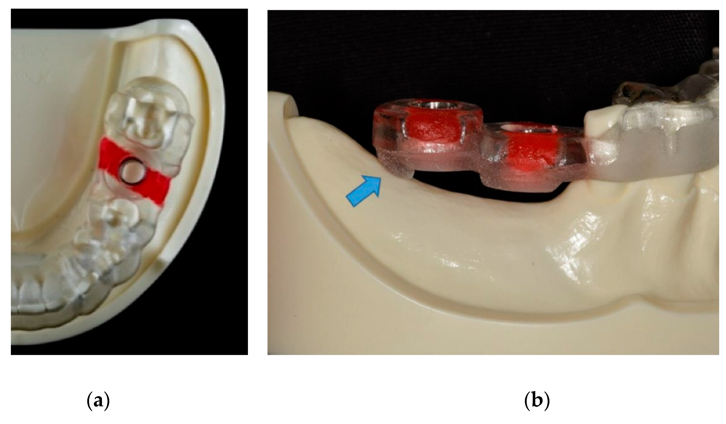
Figure 2.
Designs of dental guides for investigating the influence of the surgeon during application. (A) full dentition beam guide with all tooth surfaces included. (A1) full dentition beam guide with occlusal surfaces removed. (B) full dentition cantilever guide with all tooth surfaces included. (B1) full dentition cantilever guide with occlusal surfaces removed.
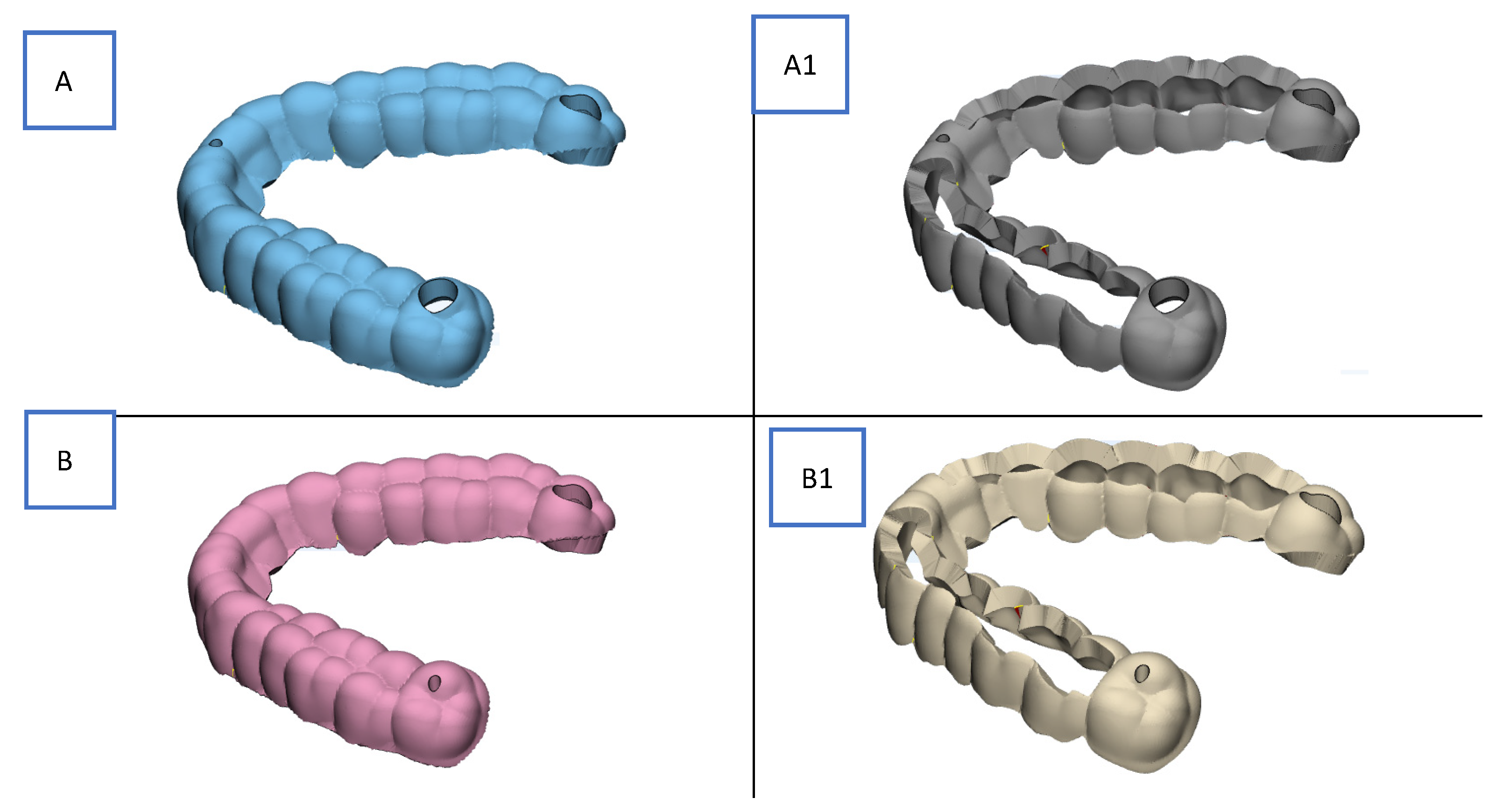
Figure 3.
Defining displacement boundary conditions for an A-type dental guide; finite element mesh (left), with all selectable displacement (clamping) boundary conditions represented by the blue zone (right).
Figure 3.
Defining displacement boundary conditions for an A-type dental guide; finite element mesh (left), with all selectable displacement (clamping) boundary conditions represented by the blue zone (right).
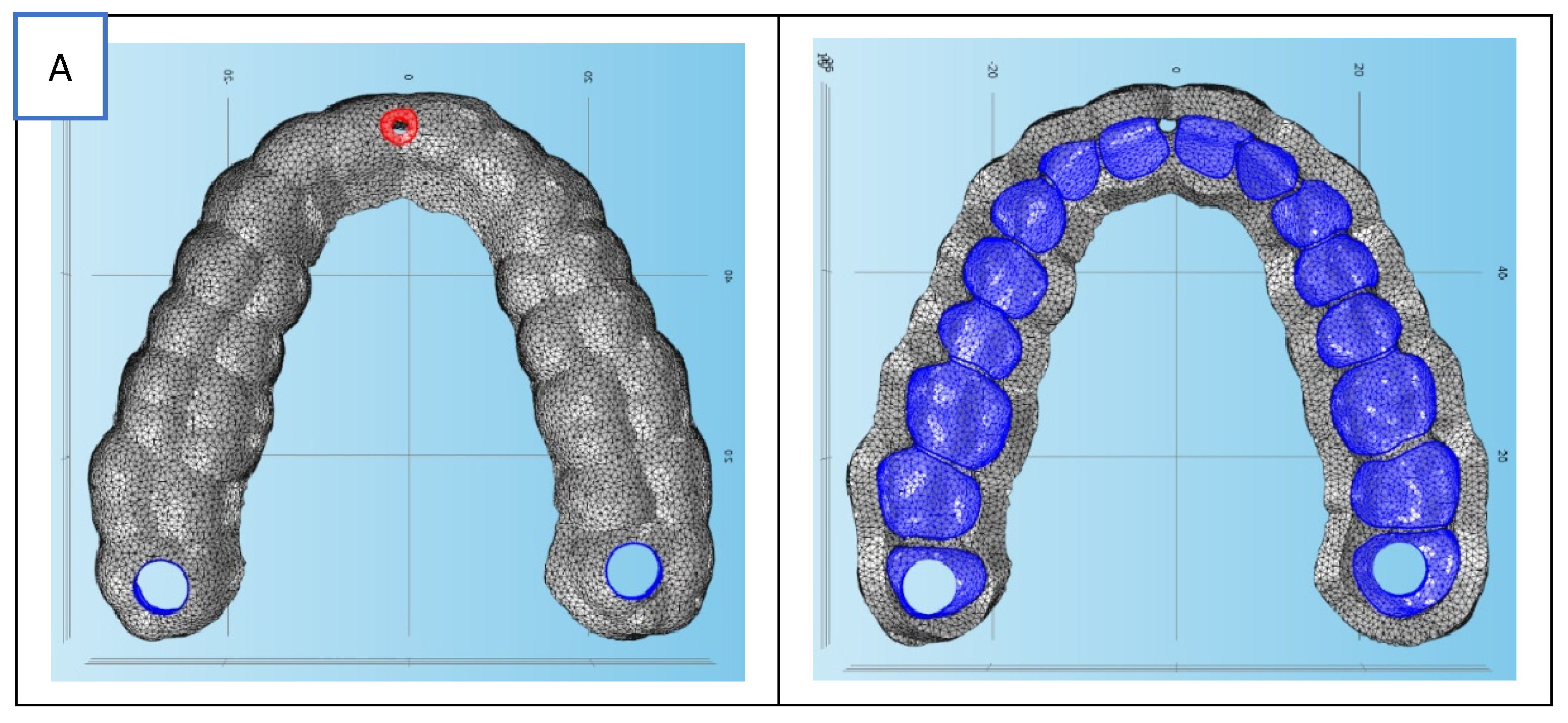
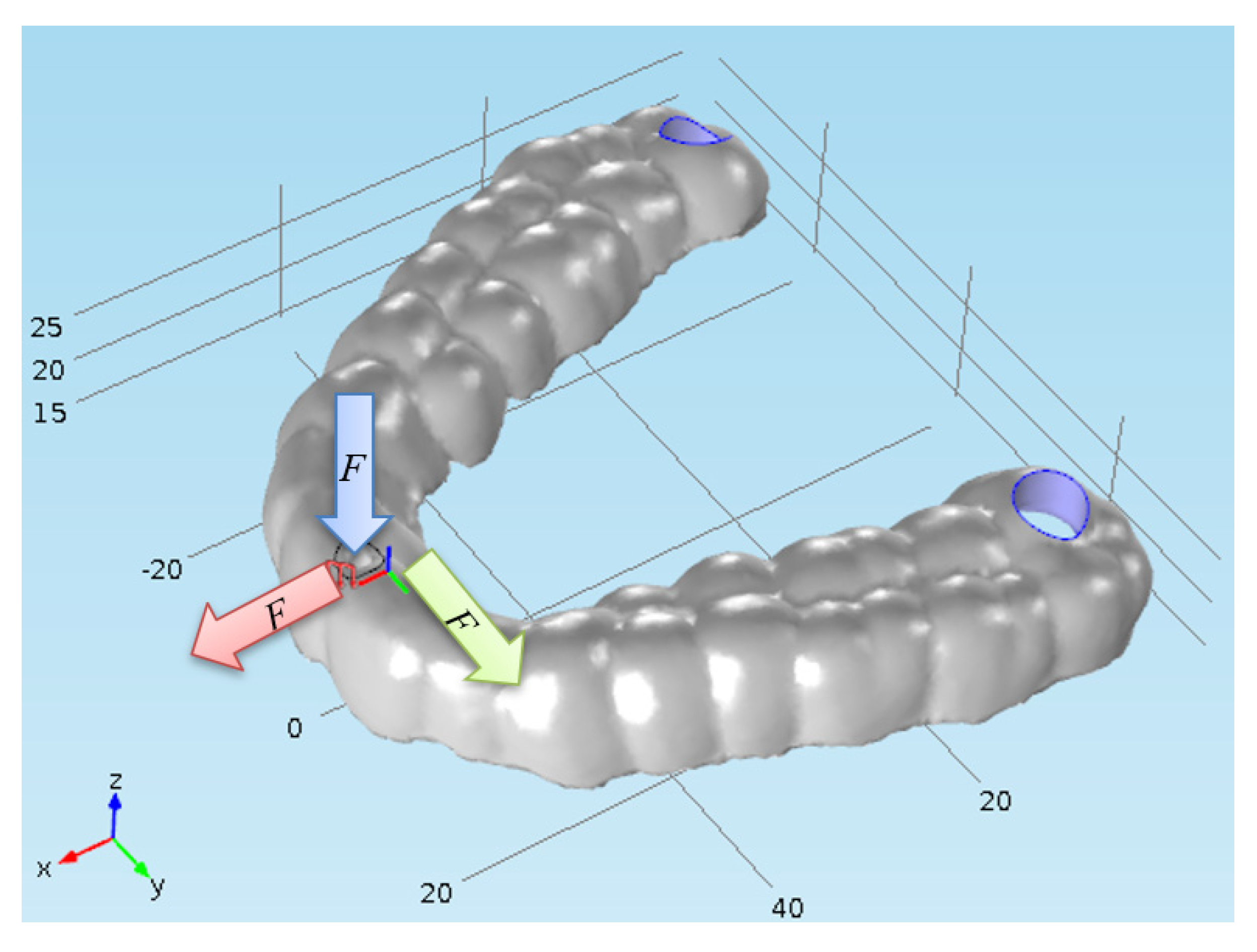
Figure 4.
Defining displacement boundary conditions – purple zone at the end of the dental guide.
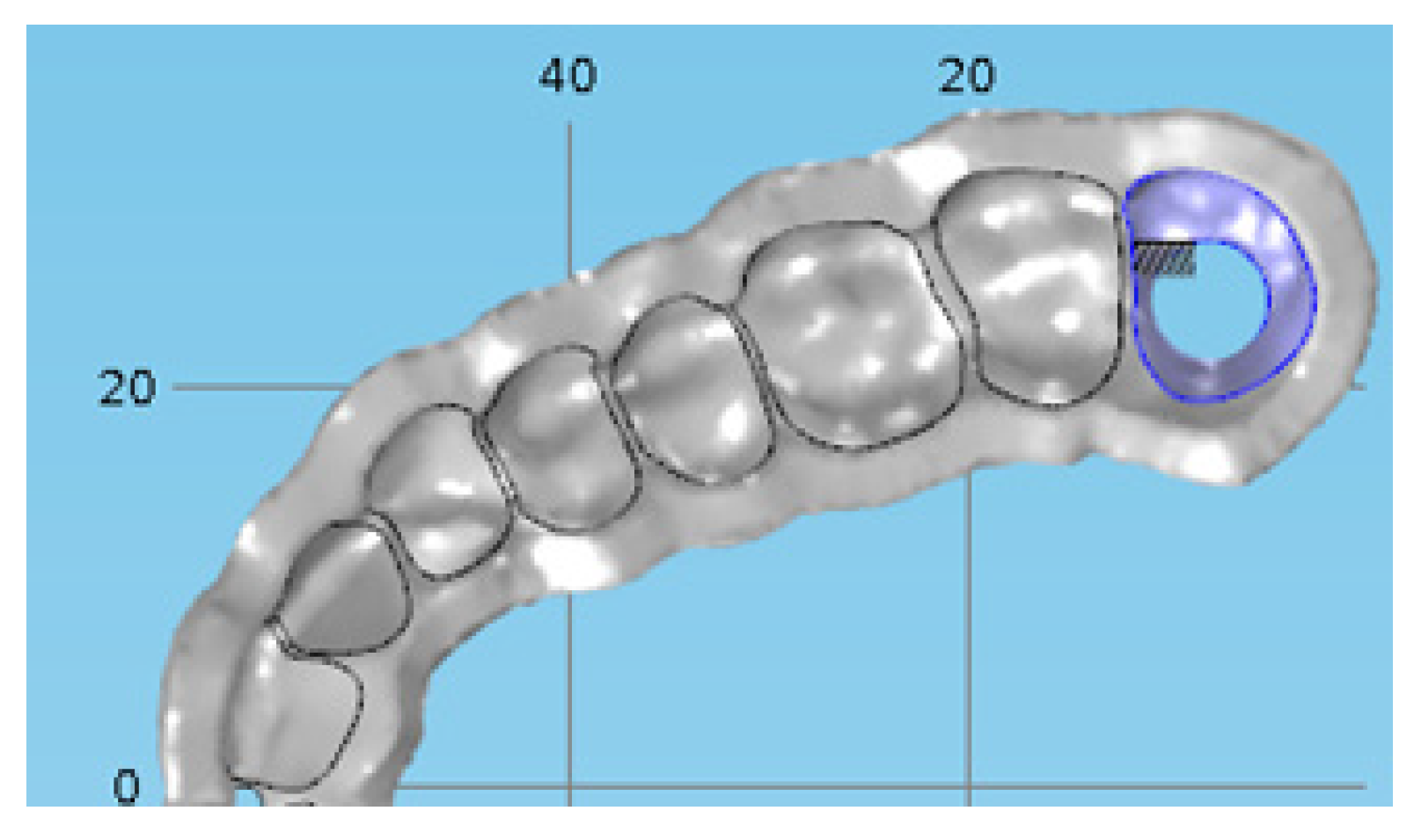
Figure 5.
Defining force boundary conditions – purple zone.
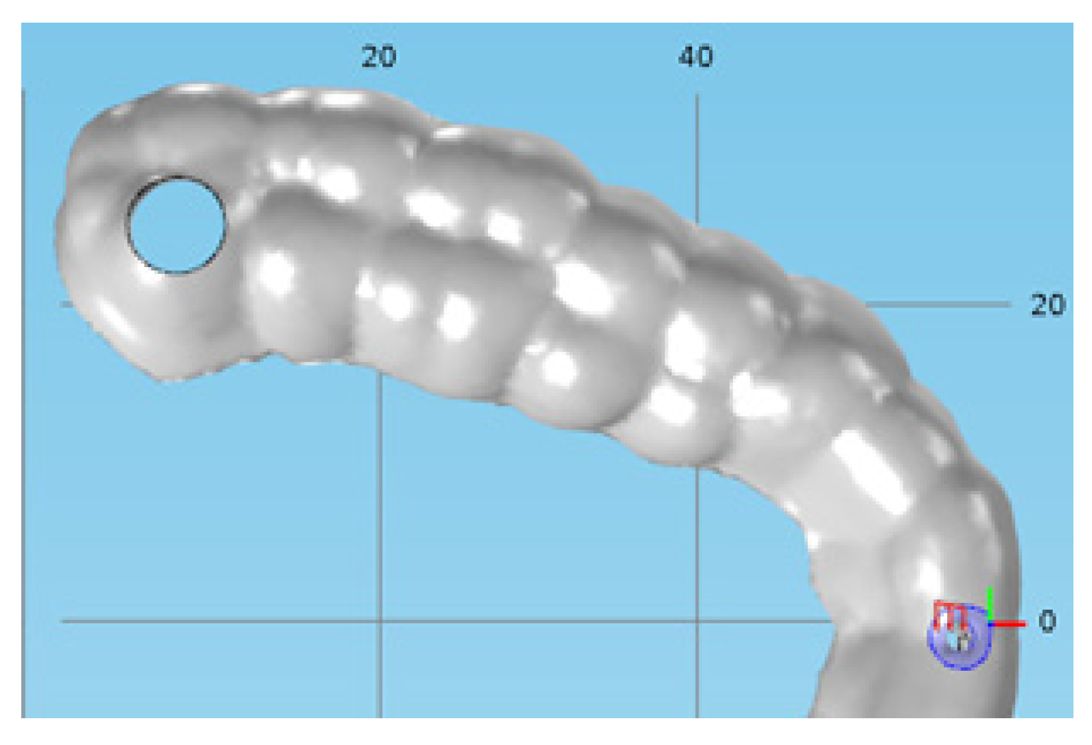
Figure 6.
The principle of sequentially adding displacement (clamping) boundary conditions one by one on a type B tooth guide is shown by the circular cycle marked with orange arrows.
Figure 6.
The principle of sequentially adding displacement (clamping) boundary conditions one by one on a type B tooth guide is shown by the circular cycle marked with orange arrows.
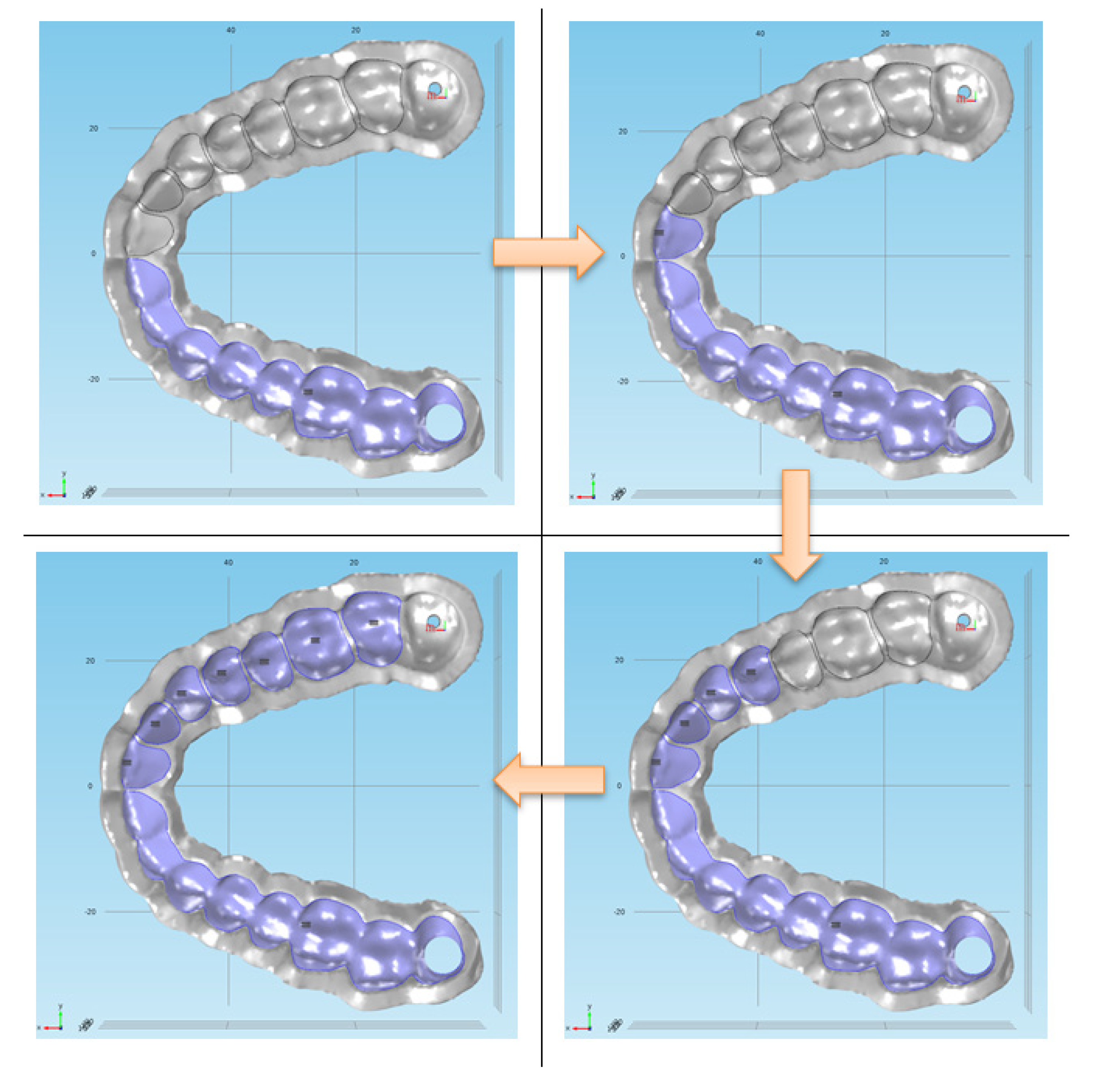
Figure 7.
The principle of sequentially adding displacement (clamping) boundary conditions one by one on a type A tooth guide is shown by the circular cycle marked with orange arrows.
Figure 7.
The principle of sequentially adding displacement (clamping) boundary conditions one by one on a type A tooth guide is shown by the circular cycle marked with orange arrows.
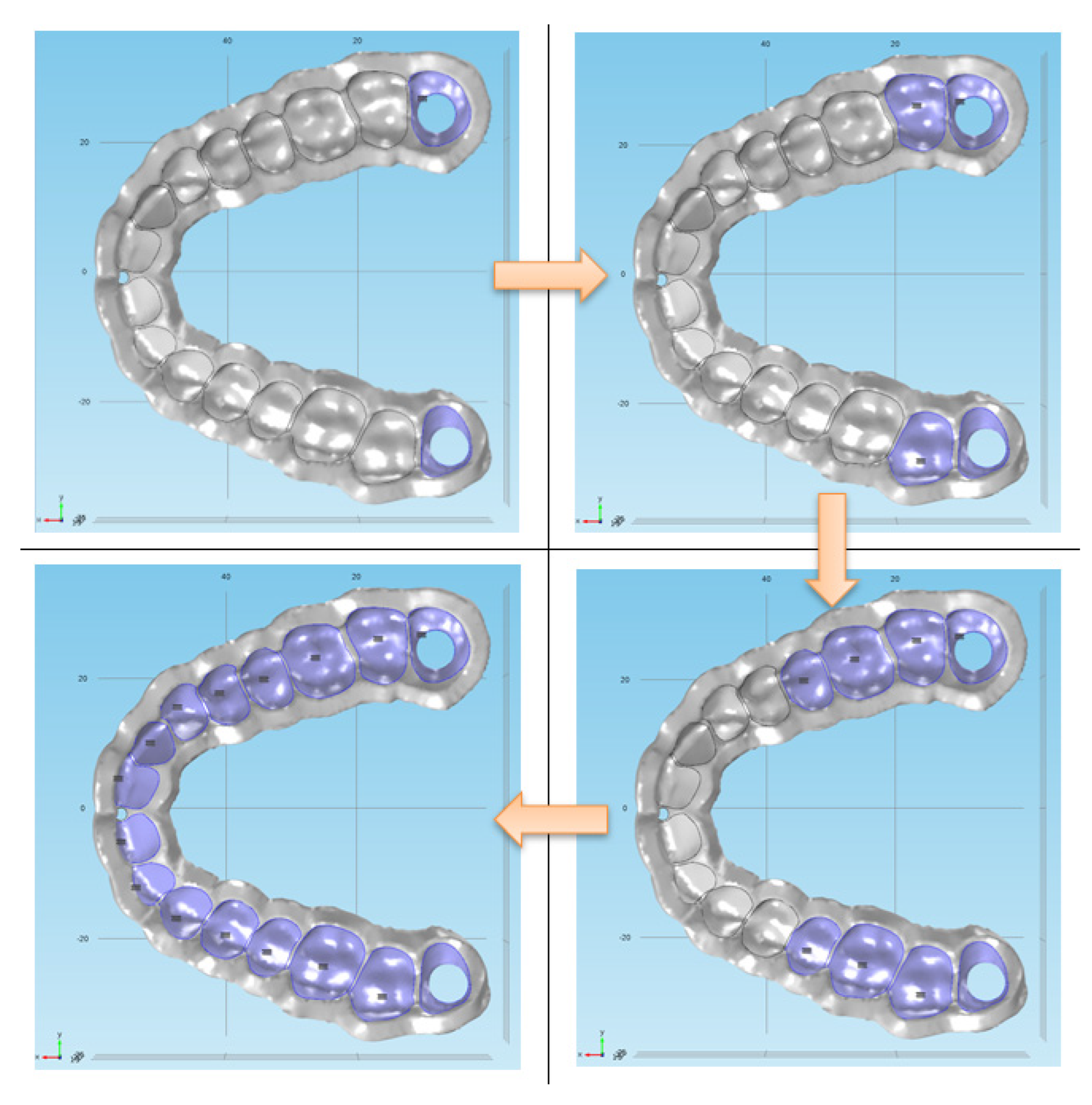
Figure 9.
Average Displacement Distribution in “-z” axes – Guide Type B.
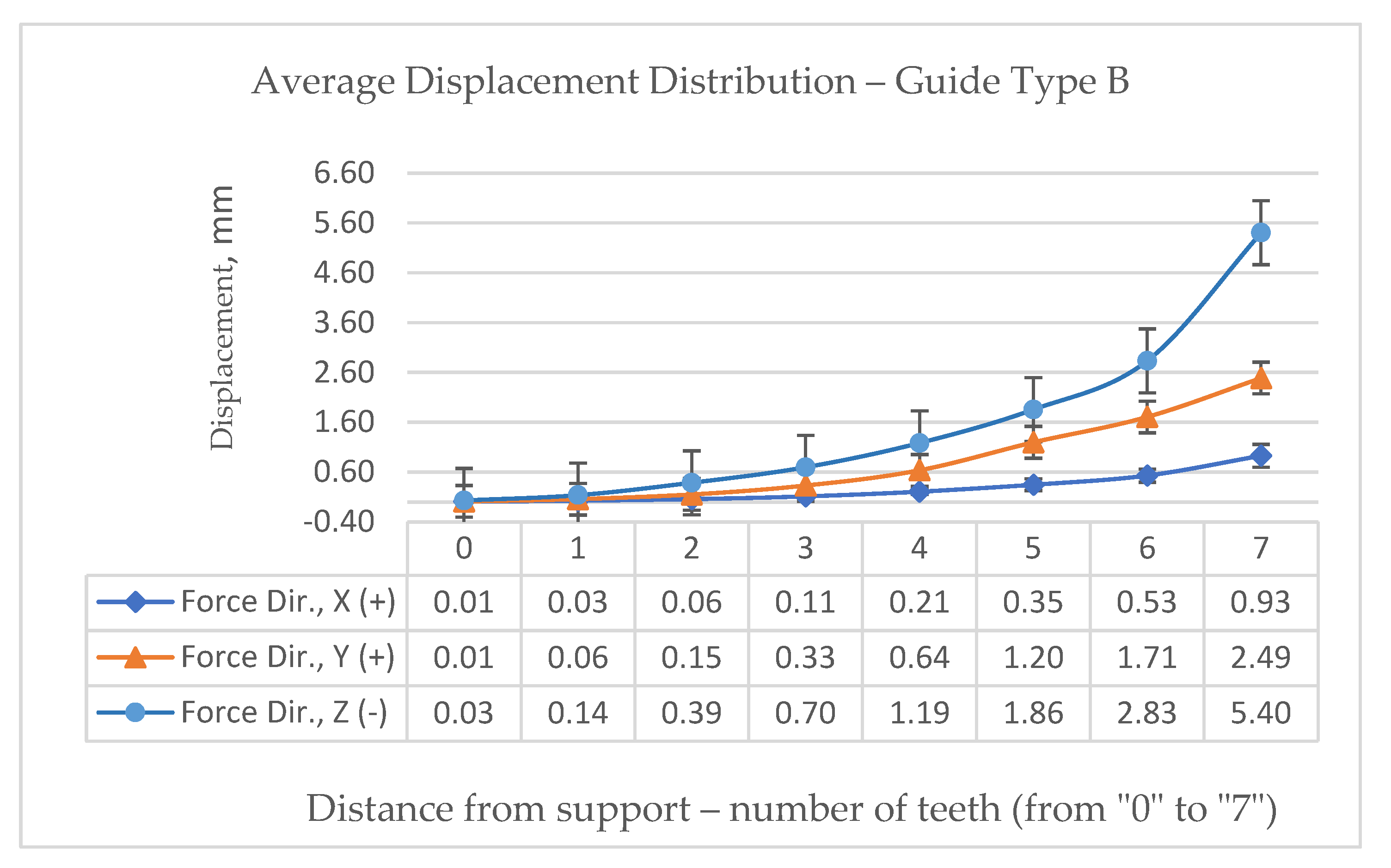
Figure 10.
Average Displacement Distribution in “-z” axes – Guide Type B1.
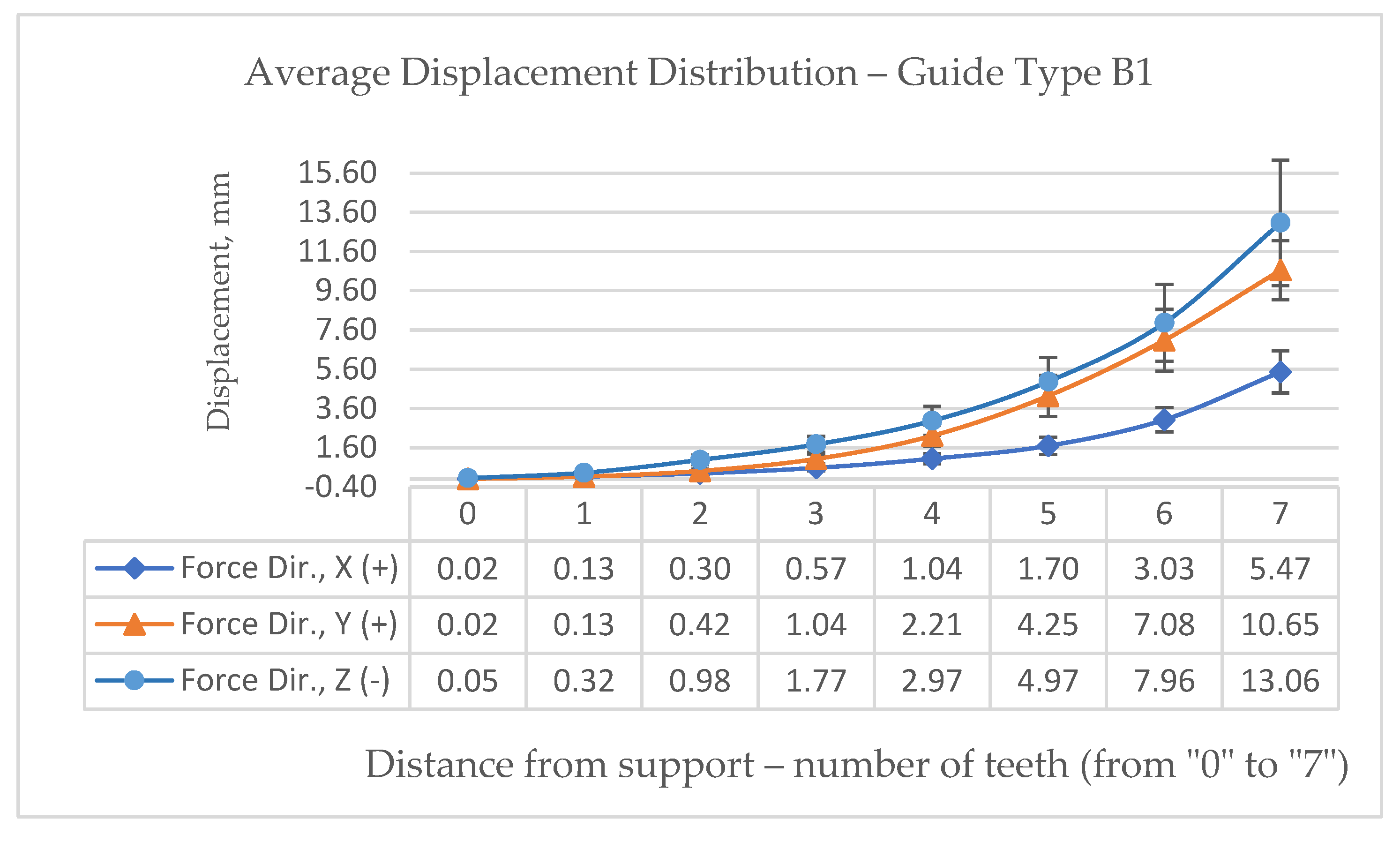
Figure 11.
Average Displacement Distribution in “-z” axes – Guide Type A.
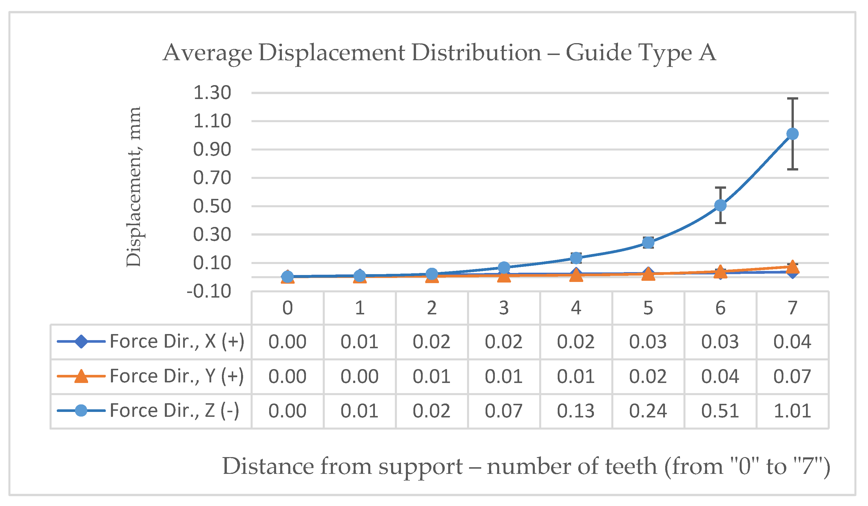
Figure 12.
Average Displacement Distribution in “-z” axes – Guide Type A1.
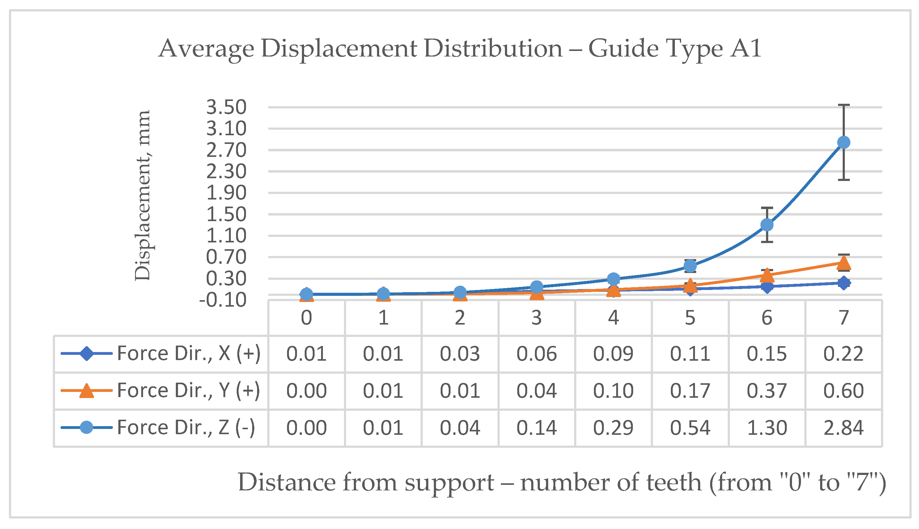
Figure 13.
Average Stress Distribution in “-z” axes – Guide Type B.
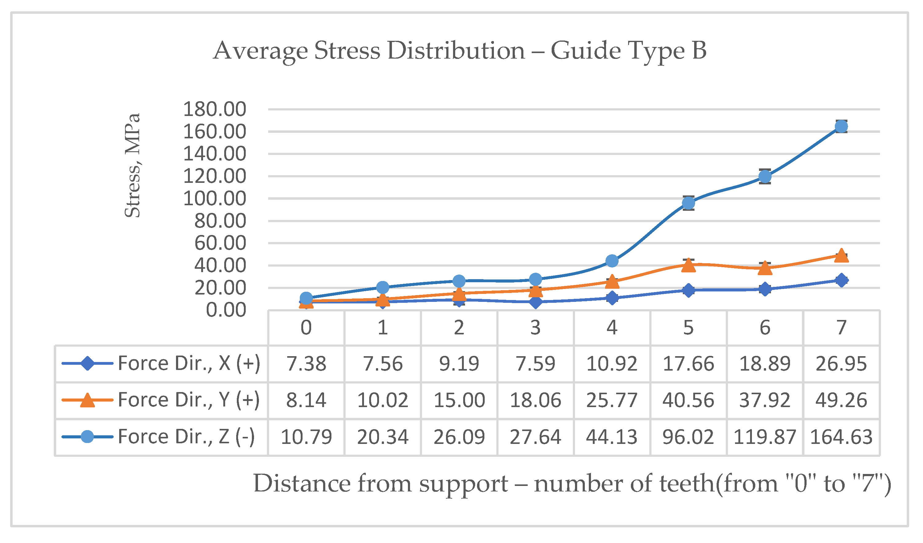
Figure 14.
Average Stress Distribution in “-z” axes – Guide Type B1.
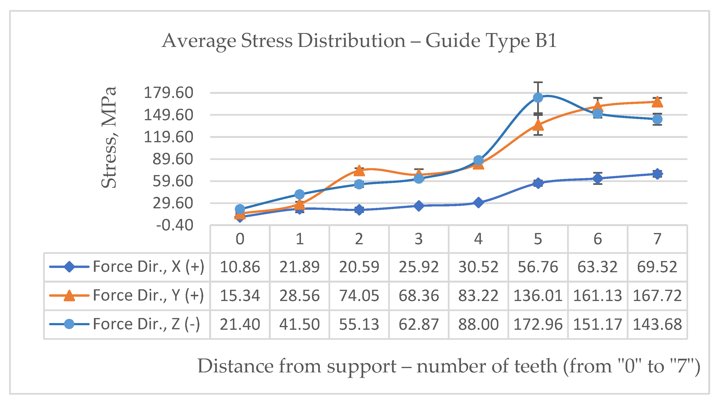
Figure 15.
Average Stress Distribution in “-z” axes – Guide Type A.
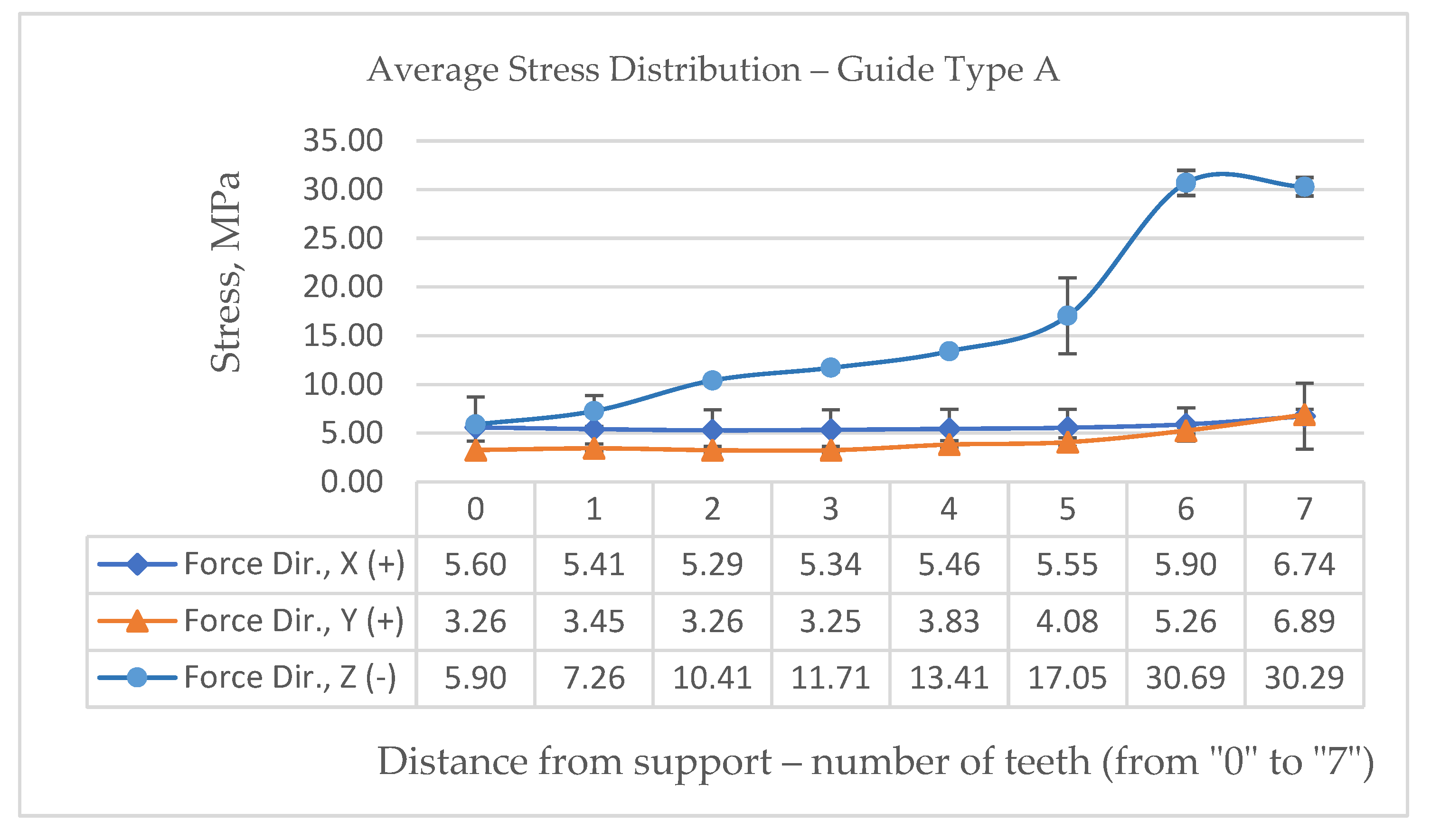
Figure 16.
Average Stress Distribution in “-z” axes – Guide Type A1.
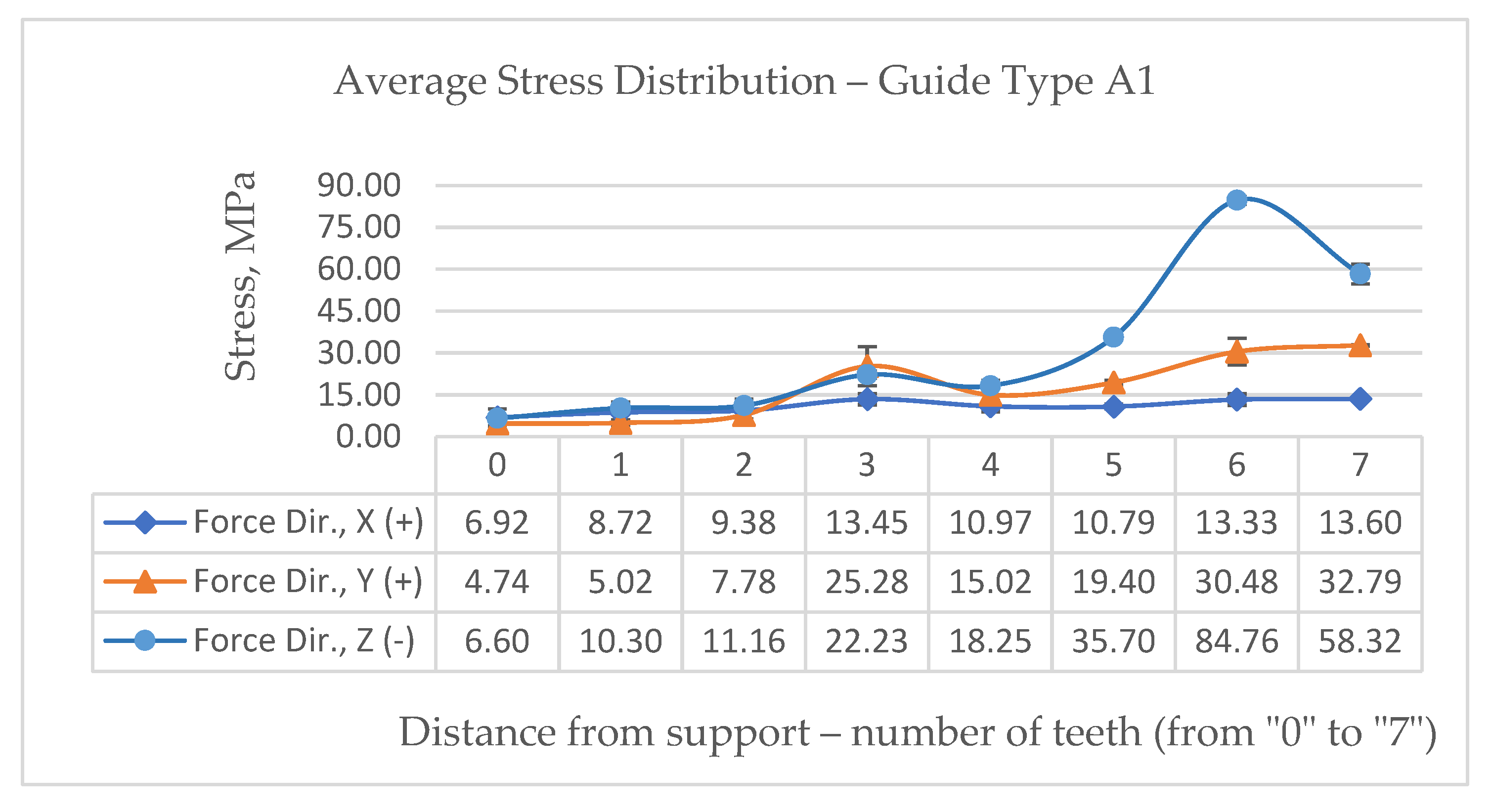
Table 1.
Finite element mesh parameters for four different designs of dental guideway.
| Dental version | FEM type | The number of finite elements in the network | Number of degrees of freedom | Density, finite elements/mm3 |
| A | Linear tetrahedral | 75118 | 397752 | 8,1 |
| A1 | Linear tetrahedral | 61966 | 338097 | 9,15 |
| B | Linear tetrahedral | 74009 | 392094 | 7,89 |
| B1 | Linear tetrahedral | 59182 | 322422 | 8,64 |
Disclaimer/Publisher’s Note: The statements, opinions and data contained in all publications are solely those of the individual author(s) and contributor(s) and not of MDPI and/or the editor(s). MDPI and/or the editor(s) disclaim responsibility for any injury to people or property resulting from any ideas, methods, instructions or products referred to in the content. |
© 2026 by the authors. Licensee MDPI, Basel, Switzerland. This article is an open access article distributed under the terms and conditions of the Creative Commons Attribution (CC BY) license.
Copyright: This open access article is published under a Creative Commons CC BY 4.0 license, which permit the free download, distribution, and reuse, provided that the author and preprint are cited in any reuse.


